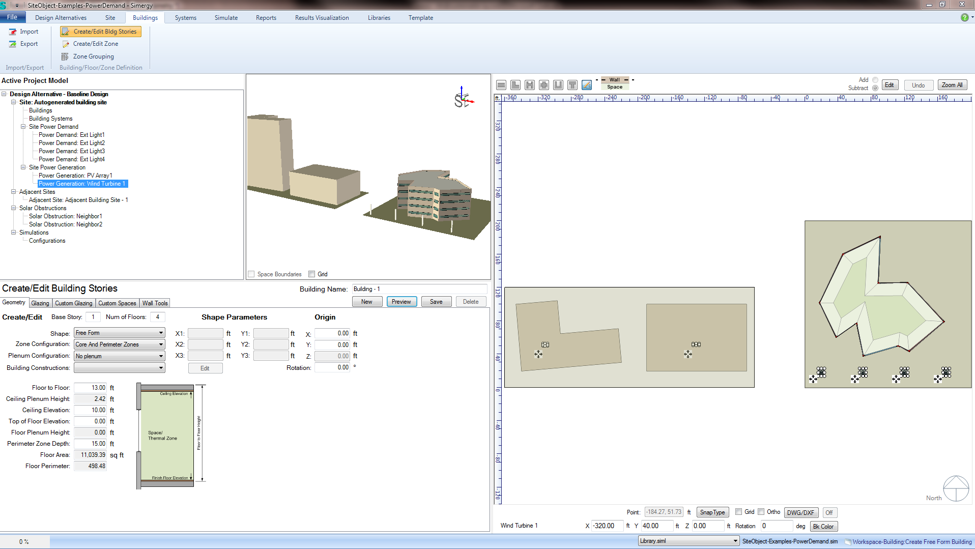
Workspace: Buildings-Building/Floor/Zone Definition-Create/Edit Bldg Stories
Workspace Areas: Active Project Model Tree - 3d view - 2d view - Create/Edit Geometry - Glazing - Custom Glazing - Custom Spaces - Wall Tools
Workflow Examples - Create a L-Shaped Building
The Building Stories tab provides a collection of tools that allow the user to create and edit geometry for their building information model. The capabilities available depend on whether the user is working with imported geometry or geometry created within Simergy.
The first step to starting the process of creating geometry is to select New. This activates different features within this tab.
Note: The user can start to create geometry without selecting New, however they will reach a point where they cannot go further and will have to start over by selecting New.
The user can click Cancel to undo any changes made to a new or existing building story.
Once the user feels the input selections are acceptable they can click Save to incorporate the geometry into the BEM. At this point the geometry has been incorporated into the model, but the overall Simergy model file has not been saved.
Note: The user can still edit the all or a portion of the geometry.
The user can select previously developed geometry and select Delete to remove it from the BEM.
The base story where the building geometry will begin to be created. The default value is "1", which means that the geometry starts at the ground (height =0'), unless specified otherwise.
Example: If creating a second building shape on top of a previously created shape that is 4 floors tall, then the second building shape would be starting on the 5th floor, so the base story value to be input would be 5.
The overall number of floors desired for the height of the building shape being created.
Example: If the user wants to build a six-story building the input value for the number of floors will be six (6).
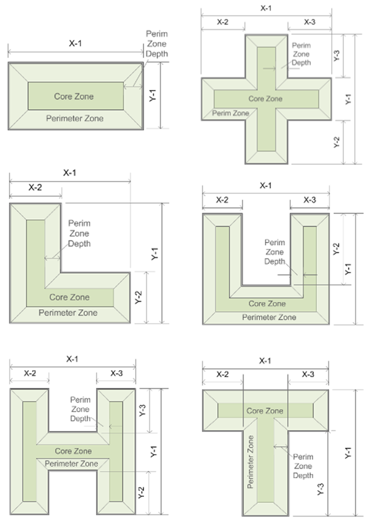
Once New is selected the Shape field is activated. The user has the choice of seven (7) shape options. The six pre-defined shapes are rectangle shape, L-Shape, H-shape, Cross shape, U-shape and T-Shape. The seventh option is Free Form, which activates the 2d model view and allows the user to draw free form shapes.
Selection of a pre-defined shape makes default values for the labeled dimensions in the corresponding diagram appear in the shape parameters fields - see "Shape Parameters" below
Selecting Free Form from the drop down list activates the 2d view allowing the user to freely draw lines defining the shape of the footprint. When the user closes the footprint (selects the endpoint for a line, which is the starting point of the footprint) a preview of the form will appear in the 3d view. The user has all the same capabilities that are available with the predefined shapes including setting the number of floors, zone configuration, floor to floor height and all the other fields. The next steps are selecting Preview and Save to associate the free form building with the Simergy model.
Selecting this will bring up a window where the user can select a drawing file to place in the plan view and trace using the free-form drawing tool.
The zone configuration that will be associated with the building geometry. There are three dropdowns for Zone Configurations: Occupied, Ceiling, and Floor. Occupied is for the occupiable spaces in the building and Floor and Ceiling are for plena or voids. The available options for Occupied Zones are:
Core and Perimeter Zones - shown in the diagrams above. The perimeter zone depth is determined by the value in the perimeter zone depth field (default: depth = 15 ft)
The available options for Floor and Ceiling Zones are:
The user specifies the plenum configuration that will be associated with the building geometry. The available options are:
The diagrams below are the floor sections that appear with the selection of different plenum configuration options. The list of options above is show left to right starting with "no plenum". If space is allowed for a plenum, but "no plenum" is specified, a "void" will fill that space.
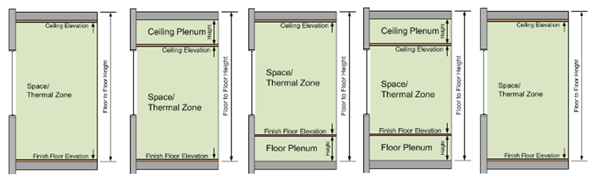
Specifies the overall height of a building floor. Default value = 13 ft.
Example: If a user entered 15 ft. and the building included six (6) floors, the overall height of the building would be 90 ft.
A calculated value that is derived from taking the Floor to Floor value and subtracting the depth of both the ceiling material and the Ceiling Elevation. The background color of the cell is gray, which indicates that the user cannot enter a value directly into this field.
The user can enter a value for the desired height between the finish floor elevation and the ceiling elevation.
The dimension between the top of rough floor and the top of Finish Floor Elevation. Note: the user is required to enter a value > 0 ft in this field before either Below Floor or Above Ceiling and Below Floor plenum configurations can be selected.
A calculated value that is derived from taking the Top of Floor Elevation value and subtracting the depth of both the Finish Floor Material. The background color of the cell is gray, which indicates that the user cannot enter a value directly into this field.
The depth that the perimeter zones for the Core and Perimeter Zones and the Two Zones per Floor Zone Configurations will be set and visually shown. The default value = 15 ft.
A calculated value of the area of the overall building geometry that is shown when the user selects Preview.
Note: The background color of the cell is gray, which indicates that the user cannot enter a value directly into this field.
A calculated value of the perimeter of the overall building foot for the geometry that is shown when the user selects Preview.
Note: The background color of the cell is gray, which indicates that the user cannot enter a value directly into this field.
The X, Y and Z set of fields that allow the user to define the size of building objects. Different pre-defined shapes will have different available parameters.
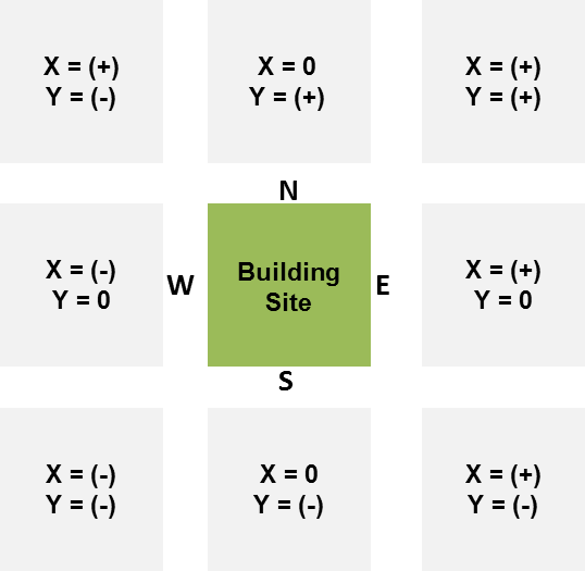
The origin point for the site the Site Object can be entered in the X, Y and Z fields (if applicable). See diagram below for X and Y origin values (positive, negative or 0) based on location to the building site.
The user can enter a value between 0 and 360 to set the orientation of the model. Entering a value in the field and then selecting elsewhere associates that value with the model and the north arrow in the 2d view will adjust to correspond. The 0 to 360 degrees range is in a clockwise direction where 180 deg. = South, 225 deg. = Southwest, and so on.
______________________________________________________________________________________
© Copyright 2013 Simergy, Sustainable IQ, Inc.