Related Topics - Geometry - Custom Glazing - Custom Spaces - Wall Tools - Building Canvas
The glazing tab provides a collection of tools that allow the user to change the glazing from the default window array running the length of each wall to a number of different configurations.
The save feature as found on the Geometry tab, which starts the process of creating geometry by selecting New.
Note: The user can start to create geometry without selecting New, however they will reach a point where they cannot go further and will have to start over by selecting New.
The user can click Cancel to undo any changes made to a new or existing building story.
Once the user feels the input selections are acceptable they can select Save to incorporate the geometry and glazing design into the BEM. At this point the geometry has been incorporated into the model, but the overall Simergy model file has not been saved.
Note: The user can edit the all or a portion of the geometry.
The user can select previously developed geometry and select Delete to remove it from the BEM.
Allows the user to select what the overall window layout framework per floor is going to be. The selection can be for the overall building geometry when it is being created or it can be to edit a floor or surface after it has previously been created. The selection establishes the framework for all four facade orientations, but the user has the choice whether they implement it on the facade or not. The selection options from the drop down list are:
| Types | Descriptions | Default Values |
| No Windows | All windows removed | Win/Wall Ratio = 0% |
| One Window Array | [Default] One array of windows is specified for the set of four facades. Each has a row in the table and can have different input values. Strip windows can be created by inputting "0" in the window width cell or specific width for the typical window can be input. See | For ALL orientations
Win/Wall Ratio = 30% Win Top Elev = 10 ft |
| Two Window Arrays | Adds a second array table to the workspace area that allows the user to incorporate a second plane of arrayed windows. Array One is vision glazing and by default Array Two is set above vision glazing array in daylight glazing area. | Array One: Vision
Win/Wall Ratio = 20% Win Top Elev = 7 ft Array Two: Daylight Win/Wall Ratio = 10% Win Top Elev = 10 ft |
| Three Window Arrays | Adds a third array table for a spandrel glazing array. This is the highest degree of complexity that can be incorporated into the building using these features. | Array One: Vision
Win/Wall Ratio = 20% Win Top Elev = 7 ft Array Two: Daylight Win/Wall Ratio = 7% Win Top Elev = 10 ft Array Three: Spandrel Win/Wall Ratio = 5% Win Top Elev = 2.5 ft |
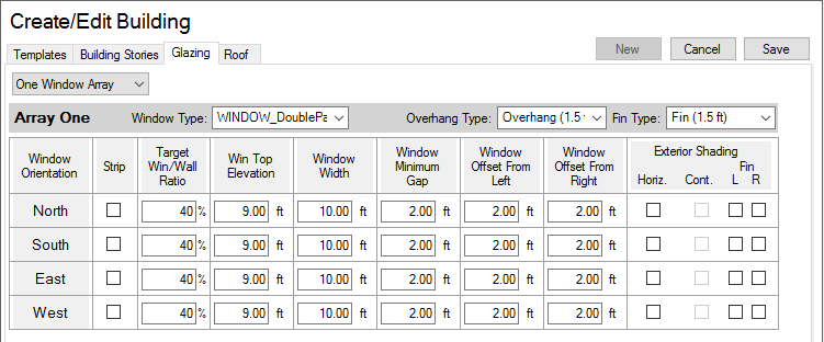
Enables you to create and customize the facade configuration incorporated into the BEM for all four facade orientations (one row displayed for each). The additional Array Tables that are added when the user selects Two Window Arrays or Three Window Arrays are the same, but the user needs to think about how all of the Array tables interact with each other in terms of the glazing plane vertical locations in proximity to the other glazing planes. The following are things to consider when working with more than one window array:
The basic structure of the Array Table is that it provides a row for each window orientation (North, South, East, West) where values can be entered or left blank for a number of features that will influence the facade configuration. In addition, the user can make choices related to the glazing/window type and the exterior shading.
Note: If the building geometry is composed of walls created with the free form tool, which are at different angles, the following rules apply:
Example 1: If a wall on the south side of the building form is drawn at an angle of negative 30 degrees, the wall will be associated with the South Window Orientation row
Example 2: If a wall on the south side of the building form is drawn at an angle of negative 70 degrees, the wall will be associated with the East Window Orientation row
[Appears with each Array Table] Based on your Library Type selection of Window Type, the field name will adapt to align with that selection and the corresponding drop down list of available options will be related to the options in the source library for that template category. When you make a selection you are applying it to the overall Array Table. A different Glazing/Window Type can be specified for each Array Table, allowing you to have multiple window types included on a facade if they have specified two or three arrays and have selected a different Window Type for each.
Tip: To change Glazing/Window type per facade or per window, the desired window or set will need to be selected and then the type can be changed on the Custom Openings Tab.
[Appears with each Array Table]
You can select an overhang type from the options available within the Solar Shading library category to associate with the facade orientation or you can create your own.
Note: Selections in the Solar Shading column need to be made to activate the drop down list.
[Appears with each Array Table]
You can select a fin type from the options available within the Solar Shading library category to associate with the facade orientation or you can create your own.
Note: Selections in the Solar Shading column need to be made to activate the drop down list.
For examples of how the following properties influence how the glazing is created, see the Percentage Glazing Examples.
Enabling String for a specific array will create one long window instead of the array of windows. Window Width and Window Minimum Gap are disabled when this option is enabled.
The input field for the Window to Wall Ratio (%) where the user can easily set and adjust the amount of glazing per facade. The Win/Wall ratio can be entered when creating geometry and/or when refining previously created building geometry. Default value for a single array is 30% for all orientations. Default values for multiple arrays are provided in the table above.
Sets the limit for how high the windows will be on the facade. It is one of the parameters that influences how the Win/Wall Ratio percentage is applied to a facade. If a user inputs a window to wall ratio that is possible based on the boundaries that have been defined, the user will receive an error message.
Allows the user to set the width for a windows in an array. The value entered is consistently used across the full array. This input value combined with the Window Minimum Gap value allow the user to establish the use of punched windows on the facade.
Note: Influences the maximum % of windows per facade that can be entered. Not enabled when Strip is enabled
Sets the spacing between the windows in the array.
Note: Influences the maximum % of windows per facade that can be entered. Not enabled when Strip is enabled.
Establishes the starting point of the window array on the left side of the facade.
Note: Influences the maximum % of windows per facade that can be entered.
Establishes the starting point of the window array on the right side of the facade.
Note: Influences the maximum % of windows per facade that can be entered.
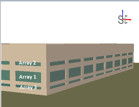
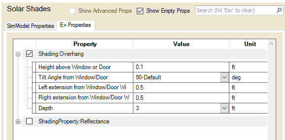
By default no shading is included on Simergy BEMs. To add horizontal shading the user can select an Overhang library entry for the selected Array and enable the "Horiz" check box for the desired facade/array. This applies the overhang to the window array that has been specified. If the window array is a continuous band of windows then the overhang will be at the top of the window and run the length of the band of glazing. However, if the array has been specified as an array of punched windows then the overhang shading will be located above each window for the width of each window - continuous shading can be enabled by selecting the "Cont" checkbox.
Note: The depth of a horizontal exterior shading device is set by the library entry, which is selected by the user from the Overhang Type drop down list. Therefore if the user desires to utilize different depths of exterior shading device they will need to create the library entries for those different exterior shading device designs before hand, so that they will be available from the drop down list. The image below shows the properties for the Solar Shading Overhang library entries.
Tip: When creating Solar Shade Library Entries incorporate the projection depth within the Library Entry title so that is easier to select from different ones.
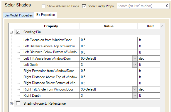
By selecting the check box the user can include vertical fins on the elevation for the full height of the window. If the window array is a continuous band of glazing the fin will only be shown on one end. The user can specify to place fins on the left, right, or both sides of the windows by enabling the L and R checkboxes.
Note: The depth of a vertical exterior shading device is set by the library entry, which is selected by the user from the Overhang Type drop down list. Therefore if the user desires to utilize different depths of exterior shading device they will need to create the library entries for those different exterior shading device designs before hand, so that they will be available from the drop down list. The image below shows the properties for the Fin Library Entry, and demonstrates that the fin can be specified to be located on either side of the window and the depth of projection is a property that can be changed.
Tip: When creating Solar Shade Library Entries incorporate the projection depth within the Library Entry title so that is easier to select from different ones.
Click the links to see demonstrations of the features in the glazing tab:
______________________________________________________________________________________
© Copyright 2013 Simergy, Sustainable IQ, Inc.