The 2d canvas appears in both the Building and Site Workspaces. The 2d view displays the BEM geometry in plan view based on what floor and/or space is being worked on. The user can also display imported DWG/DXF plans or plans from IFC models that have been imported. A description of what is an active selection is provided in the lower left of the 2d view.
In addition to the features described below, the main field contains edge rulers on both x and y axis (default = feet) and a North Arrow (lower right).
The user can select objects directly in the 2d view or they can make selections via the Active Project Model Tree or the 3d View that will then display as active in the 2d view. At any time an object is selected, the user can right click and access additional features to refine the selection, jump to other aspects of the model or initiate different commands. A description of the right click features is provided in Active Project Model Tree.
The user can actively pan the 2d view at any time by positioning the mouse anywhere within the 2d canvas, right click the mouse, and while keeping it pressed move the mouse to pan around the 2d canvas.
To dynamically zoom in and out in the 2D view, position the cursor inside the 2D view and then use the mouse wheel to dynamically zoom. Moving the mouse wheel TOWARDS the user ZOOMS OUT and moving the mouse wheel AWAY from the user ZOOMS IN.
Selecting Zoom All will zoom to the extents of the current model. In the 2D viewport, this will zoom to the extents of the site if no building is present; if there is a building, the camera will zoom to fill the viewport with the building extents.
On the upper left area of the workspace are seven (7) shape icons. Six(6) pre-defined shape options and a free-form tool icon. The icons will be active when the user is either creating or editing previously created geometry. When the icons are active selecting any of the six (6) pre-defined shapes will make the features associated with that shape active in the Create/Edit Building Stories area of the workspace. Selecting the "Free Form" icon activates the 2d drawing canvas allowing the user to draw free form shapes using the Simergy drawing tools. In addition, the user is presented with the option of where the drawing selection on the 2d view starts (Left of Wall, Center of Wall [default], Right of Wall).
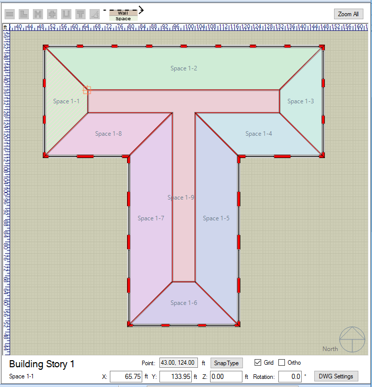
The lower band of the 2d view area contains a number of additional features
The point field reports the x and y coordinates (in that order) for the current location of the cursor on the 2d view. Default = feet.
Clicking on Snap Type presents the user with (6) of the typical snap options that are available within other modeling tools. They are:
By selecting or deselecting the check boxes the user can turn on or off the snaps.
Tip: to reduce the amount of snap options presented when trying to select or draw free form shapes it is recommended that End Point and Perpendicular are the best selections.
By selecting or deselecting the check box the user can turn on or off the grid in the 2d view.
By selecting or deselecting the check box the user can turn on or off the Ortho command. Ortho allows the user to draw explicitly straight lines paralell to either the X or Y axis.
Tip: Ortho allows the user to point the line in a direction and select a snap point in that direction, but not explicitly on that line to make the selection.
Selecting DWG Settings brings up the Layers dialog to import a DWG/DXF file or edit the settings for one already imported.
The On/Off controls if the dwg/dxf file is being displayed on the 2d view or not.
Input fields for the X, Y, and Z coordinates that can be utilized by the user.
The user can enter a value between 0 and 360 to set the orientation of an object. Entering a value in the field and then selecting elsewhere associates that value with the model and the north arrow in the 2d view will adjust to correspond. The 0 to 360 degrees range is in a clockwise direction where 180 deg. = South, 225 deg. = Southwest, and so on.
______________________________________________________________________________________
© Copyright 2013 Simergy, Sustainable IQ, Inc.