Related Workspaces: Site, Buildings, Systems, Libraries, Templates
Related Topics: Import IDF, Import GBXML
Video: Geometry Workflow 1 - IFC Import
Tip: Importing an IFC model and importing a DWG/DXF file are handled differently. To import a DWG/DXF to use as an underlay to create geometry or for a reference use the DWG/DXF button on the 2d view within any of the workspaces where it is displayed.
Many BIM authoring applications do not create correct second level space boundaries, which are required for energy performance simulation. Applications which DO create correct second level space boundaries are those that have been certified by GSA for correct support of the ‘Concept Design BIM’. To date, Dprofiler and ArchiCAD 17 have been certified. Revit and AutoCAD Architecture are currently in the certification testing process. Simergy imports the IFC Concept Design BIM. It is recommended that IFC files from other applications be run through the Space Boundary Tool (SBT) to generate space boundaries before importing to Simergy. SBT is a standalone tool available for free at https://gaia.lbl.gov/interoperability/SBT.
Important: to import an IFC file, it needs to be an IFC2X3 Concept Design BIM, Model View Definition
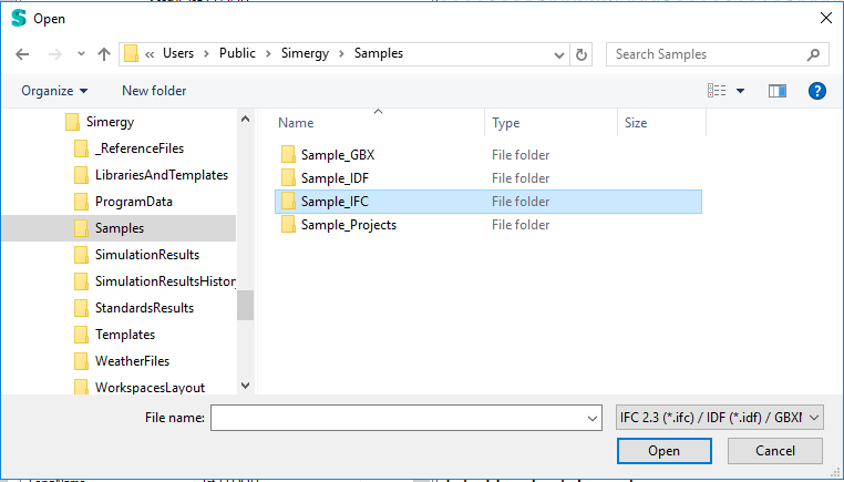
Image: Import Browser. Note the three file types that are available for import - IFC 2.3, IDF and GBXML. You don't need to select one, all three are automatically recognized.
When complete, the information about the IFC file appears in the Import/Export Model Area (Center Top)
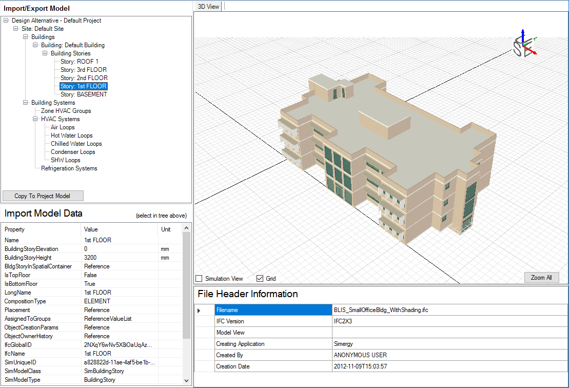
You can select on geometry components within the tree, such as Floor:Story 1 (shown below) to have information displayed in the Import Model Data area (center bottom), which can be reviewed prior to the Import Process being completed.
Important: Even though the Import Process is complete, the file has not been saved yet. Select File:Save or File:Save As to save the imported model.
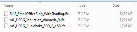
A set of sample IFC files is included with the installation package of Simergy.
If the install defaults are selected the location of the sample IFC files is - C:\Users\Public\Simergy\Samples\Sample_IFC
The sample IFC files include:
After you import an IFC file, you might be a bit confused when you go to the Buildings tab and look at the 2d view and browse the Active Project Model Tree. So, let's go through a few things:
If you were to import the IFC sample file (BLIS_SmallOfficeBldg_WithShading) and counted the total number of occupied spaces and thermal zones, you would find that the totals are different. Why are they different?
By default Simergy will import one space equal to one thermal zone, unless otherwise specified. If the IFC file that was imported had sets of spaces defined as groups, then those spatial groups will be imported as a thermal zone. Therefore multiple spaces most likely are included in one thermal zones, which will make the totals differ. The best way to check is to go to the Buildings: Create/Edit Zone Workspace and look at the Edit/Create Thermal Zones table.
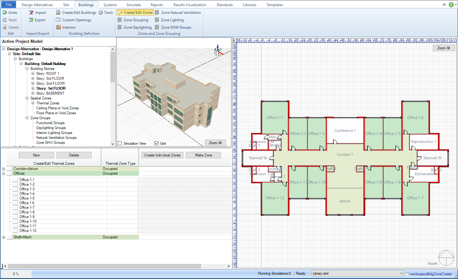
Image: The Edit/Create Thermal Zones table that displays the thermal zones and the spaces associated with those thermal zones.
By default the thermal zones are compressed, so you will not see the spaces that are associated with each thermal zone. To see the spaces, just select the "+" next to the thermal zone name.
At a minimum you will need to do some things to your imported IFC file to make it "simulation ready". The steps do not differ from if you were building a Simergy model that didn't have an imported file:
At least one Zone Group is required, so that Zone Loads and Zone Conditions can be associated with the model. See Zone Groups Workspace for more details
Remember, no information about the HVAC system will be imported into Simergy so you will need to define it. You can do that by using the predefined templates, adapting the predefined templates or creating your own. There are potentially a number of steps involved in setting up a HVAC system for your model, which will vary significantly based on the type of HVAC system included in the project design. At a minimum you will need to establish at least one (1) Zone HVAC Group. Depending on if you incorporate compound equipment in your Zone HVAC Group, which does not require Air Loops or Water Loops, you will most likely need to create those. Once you have your HVAC system defined, you will want to validate each Zone HVAC Group, Air Loop and Water Loop as a "Best Practice Approach".
To be able to view the desired output variables in Results Visualization, you will need to set up an Output Request Set Template that you can associate with the Simulation Configuration for your model prior to simulation.
______________________________________________________________________________________
© Copyright 2013 Simergy, Sustainable IQ, Inc.