The workspace provides the user the ability to assemble new templates or view ones that have been previously created in different source libraries..
Across the three Ribbon categories of capabilities there are four unique workspace types, excluding the common Import/Export workspace.
Import/Export (common) |
|
Provides the user the ability to view templates that are included with Simergy Source Libraries, adapt those templates to create new ones, or to build custom templates in combinations of ways. The Source Library can be changed by selecting a different one from the drop down list on the bottom right of the different workspaces.
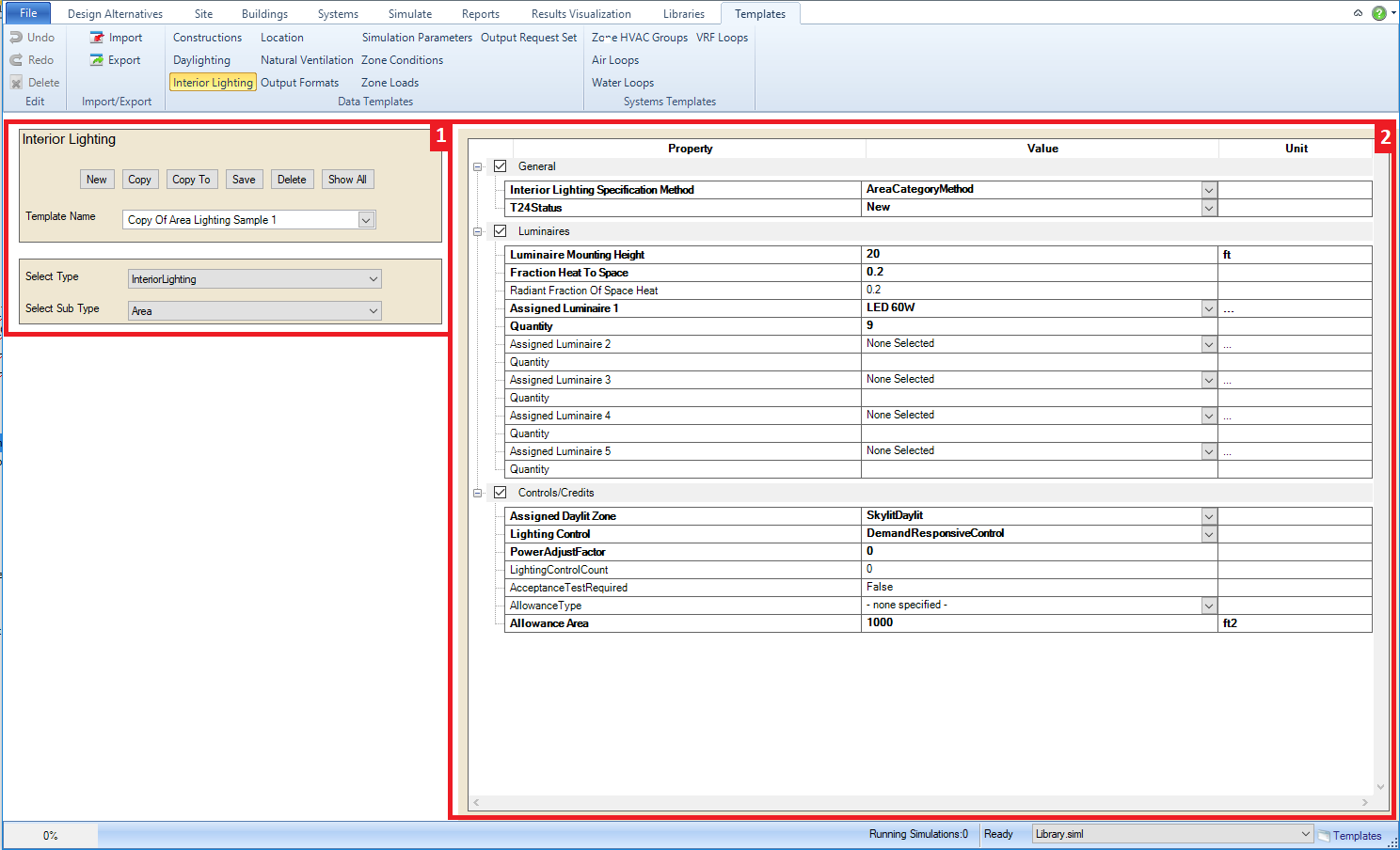
Main workspace areas:
Template Selection and Controls - allows the user to select a template from the drop down list to either view or start editing depending on the Template Category workspace that has been selected in the ribbon. If changes are made to the template selected the user has the option to Save the changes, Copy the existing and rename, create a New Template. or even delete a template.
Property Values Table - the table will present information in a number of different ways. The user can select a template from the Template Name drop down list and the table will display all of information included in that template. The information may not be fully exposed to the user because of the compression of different categories, so it is important to expand all the "+" icons to gain full understanding of the information included. By default all of the categories will be "grayed out", but they can be activated by selecting the check box for the section. It is also important to note that the variables shown in bold are variables that require values be input to enable EnergyPlus to simulate. Another option is to select New from the Template Selection and Controls field, which provides the user a blank slate and gives them access to all the variables that are associated with that Template type to begin to build a new template. The user should Just remember to type a name in and hit Save when the selections are complete.
Tip: It is impossible to describe all the different ways that the templates workspaces can be used, so we encourage users to spend some time exploring on their own and reviewing the videos to generate ideas.
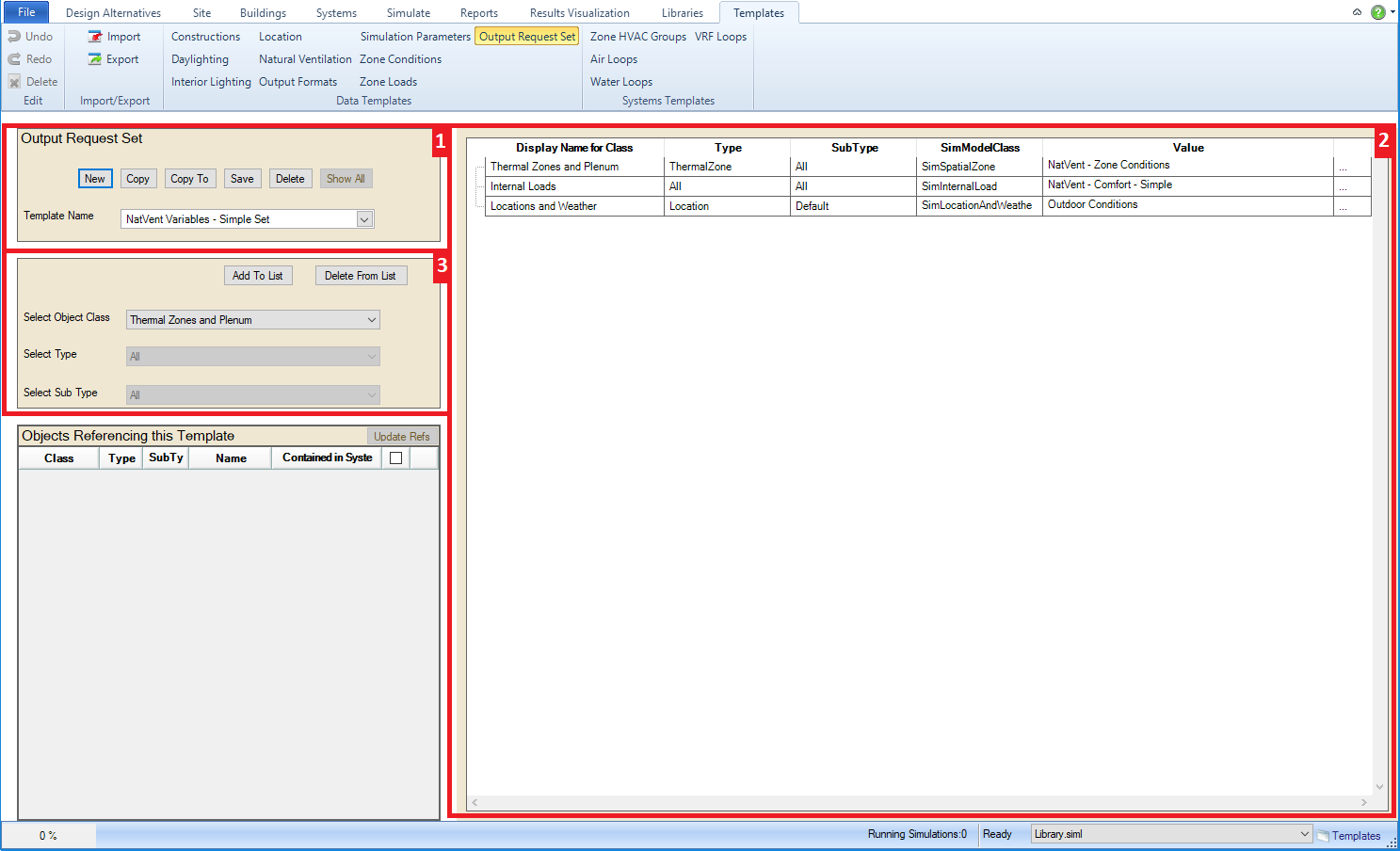
This workspace is a very important one because it enables the user to develop Output Request Sets for their simulation runs. The importance of the user selections here is that they will dictate what output variables they have available to view, investigate and interrogate results.
Main workspace areas:
Template Selection, Naming and Controls - allows the user to select a template from the drop down list to either view or start editing an Output Request Set Template. Once selected information will appear in both of the other fields. If changes are made to the template selected the user has the option to Save the changes, Copy the existing and rename, create a New Template. or even Delete a template.
Output Request Set Variables and Values - The user can select a template from the Template Name drop down list and the table will display all of output variables included in that template for the four columns of SimClass, SimType, SimSubType and Value. Note that the first three columns are the same as the three selection lines in the next field, although they are named differently. The first three columns can be a guide to identifying the pathway to other output variable options to include in the Output Request Set. Just remember that EnergyPlus contains more than 10,000 output variable and meter options to select from. The Value column provides a drop down list displaying alternative values for selection, if they exist.
Selection of Object Class, Type and Sub-type - allows the user to filter the source library database by selecting object class, type, and sub type from the drop down lists. Once the object class is selected then default selections for type and sub type appear and the options available in these two drop down lists is influenced by the previous selection. Once the desired combination is determined by the user they can select Add to List to have it included on the Output Request Sets table. The trio of selections will also be displayed when a selection is made from the Template Name drop down list providing additional context. To use Delete From List and remove rows from the Output Request Sets table the user needs to highlight a complete row in the table and then select Delete From List.
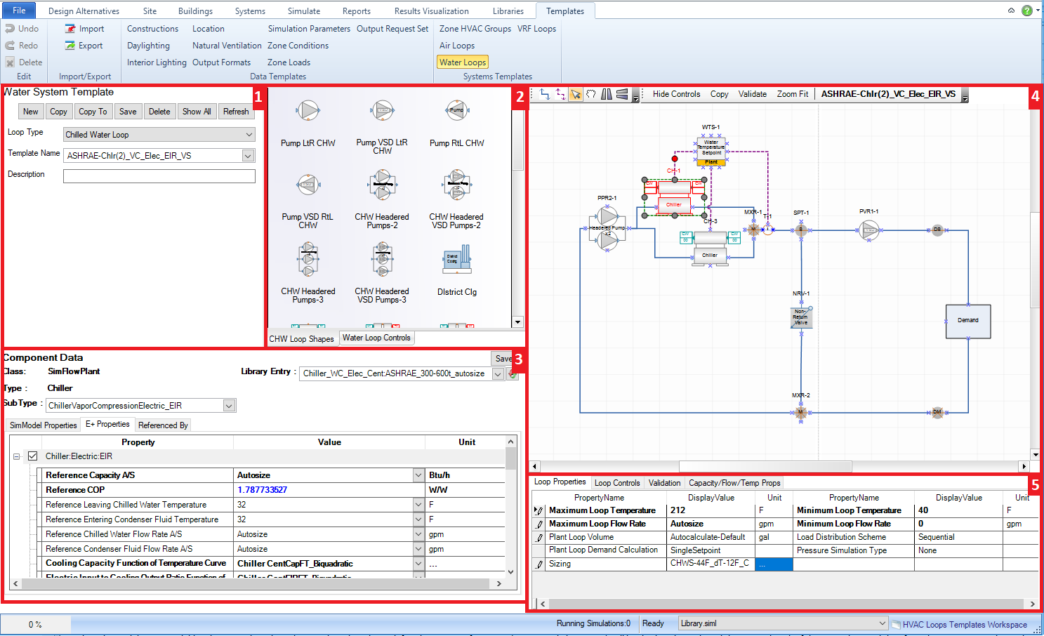
A powerful set of workspaces where Air Loop and Water Loop System Templates that are packaged with Simergy and/or constructed by others can be reviewed, edited and built. The Loop Level System Templates can be used to more quickly and effectively configure HVAC system designs in the BEM. The workspaces across the Air Loops and Water Loops are similar, so they are grouped into one category and they are a combination of the capabilities shown in both the Create/Edit and Diagram System Workspaces.
Main workspace areas:
Air Loop Template Selection and Controls - allows the user to select a Template Name to start with based on the current Source Library (selection on lower right side of workspace). In addition the user can utilize the controls to create a New template, Save one that has been edited, Copy a template, Delete one and also Validate a template that has been created or adapted. Tip: The Template Name field serves both as a drop down selection and a text entry field to change or create a new name.
HVAC diagramming stencils - Air Loop and Controls & Sensors stencils are both options to the user. They are made active by just selecting on the stencil title. The Air Loop stencil is the default and shows icons with titles to describe the available Air Loop shape components that can be incorporated into the Air Loop. Shape components can be selected from the Stencil and then dragged and dropped on the HVAC diagramming canvas to be incorporated into the current Air Loop. Each shape component has anchor points (blue x), which assist placing the shape components, as well as adding connections.
Selected Component Information (Shape Component Properties) - when the user selects a component from the HVAC diagramming canvas property information will appear in this field. The type of properties displayed will vary significantly component to component, however the line items shown above the table are common fields. For those users that are familiar with the Input Data File (IDF) structure, the property list for each component is aligned with that list. For each component Type, Sub Types and Library Entities will be shown, while shapes that contain off-page reference tags will potentially have up to four additional line items for each of the water loop types (HW, CHW, MxW, CW). Tip: Make sure a component has a Library Entity specified, otherwise the BEM will not simulate.
HVAC diagramming canvas - paints the interactive picture of the components, sensors and controls associated with the Air Loops. New components can be added from the stencils to either the supply side or the demand side, however if the user wants to change the components within the Zone HVAC Group it is recommended that it be done in the Zone HVAC Diagram workspace. New connections and connectors can be added, shapes can be moved or relocated, controls can be hidden, components can be selected to display their properties on the lower left of the workspace, the Air Loop can be validated and a number of other capabilities are at the users fingertips (think tip of the iceberg). Tip: if the user is making edits to an Air Loop design or building one from scratch, it is recommended to validate early and often to reduce potential issues later in the BEM development process..
Air System Parameters - allows the user to set parameters, such as sizing criteria, at the overall Air Loop level. Also contains System Level Controls/Validation - contains a tab for loop level controls and validation results. The user can set priorities for Availability Managers by selecting Properties, which displays a pop-up dialog where objects can be selected from the drop down list and then an available scheme can be selected. Once these have been defined summary information (priority and object type) will be displayed. On the validation results tab, if the user selects Validate from the Air Loop Template Selection and Controls field the validation results (name, system issue to be fixed, and error type) will be displayed here.
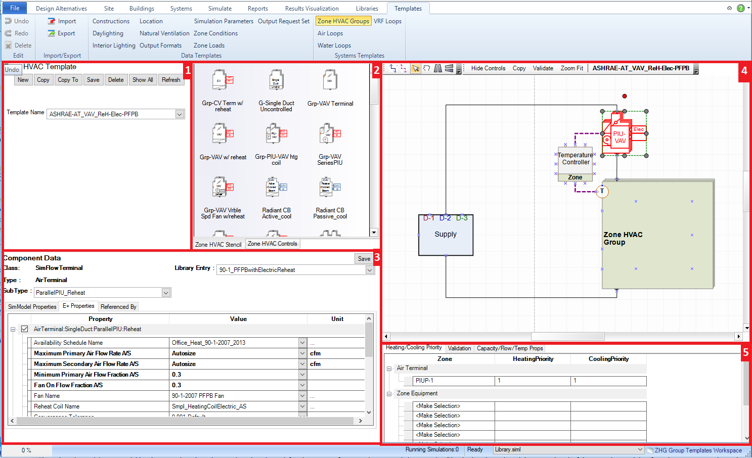
A powerful workspace for the user to become familiar with where Zone HVAC Templates that are packaged with Simergy and/or constructed by others can be reviewed, edited and built. The Zone HVAC Groups are key pieces that can be used to design different types HVAC systems for the BEM. The Zone HVAC Groups Template workspace is a combination of the Zone HVAC Group Create/Edit and Diagram Workspaces found on the Systems tab.
Main workspace areas:
Zone HVAC Template Selection - allows the user to select a Template Name to start with based on the current Source Library (selection on lower right side of workspace). In addition the user can utilize the controls to create a New template, Save one that has been edited, Copy a template, Delete one and also Validate a template that has been created or adapted. Tip: The Template Name field serves both as a drop down selection and a text entry field to change or create a new name.
HVAC diagramming stencils - Zone HVAC Stencil and Zone HVAC Controls & Sensors stencils are both options to the user and they are made active by just selecting on the stencil title. The Zone HVAC stencil is the default and shows icons with titles to describe the available Zone HVAC equipment that can be incorporated into the Zone HVAC Group. Shape components can be selected from the Stencil and then dragged and dropped on the HVAC diagramming canvas to be incorporated into the Zone HVAC Group. Each shape component has anchor points, which assist placing the shape components. Those anchor points will snap to the anchor points (blue x) that are located within the Zone HVAC Group shape and indicate a maximum number of shape components that can be associated with a Zone HVAC Group.
Selected Component Information (Shape Component Properties) - when the user selects a component from the HVAC diagramming canvas property information will appear in this field. The type of properties displayed will vary significantly component to component, however the line items shown above the table are common fields. For those users that are familiar with the Input Data File (IDF) structure, the property list for each component is aligned with that list. For each component Type, Sub Types and Library Entities will be shown, while shapes that contain off-page reference tags will potentially have up to four additional line items for each of the water loop types (HW, CHW, MxW, CW). Tips: Make sure a component has a Library Entity specified, otherwise the BEM will not simulate. If a property is displayed in Bold Text it is required to have a value to simulate EnergyPlus
HVAC diagramming canvas - paints the interactive picture of the components, sensors and controls associated with the Zone HVAC Group. New components can be added from the stencils within the Zone HVAC Group shape or outside of it (Air Terminal Shape variations, shared supply and/or return plenums and controllers), new connections and connectors can be added, shapes can be moved or relocated, controls can be hidden, components can be selected to display their properties on the lower left of the workspace, the Zone HVAC Group can be validated and a number of other capabilities are at the users fingertips (think tip of the iceberg). For example, if an air terminal component is selected and the user wants to change the sub type, then can select a different one in the component properties and when they select update the air terminal shape will change to the new sub type that has been selected. Tip: Note that when a user is editing a Zone HVAC Group when they leave that workspace it is automatically saved
System Level Controls/ Validation -This field has tabs for setting the heating/cooling priority and a second tab for displaying validation findings. The user can set the heating and cooling priority for air terminals and zone equipment separately. When equipment is added to the Zone HVAC Group the name of the component will automatically be added to the table. To set the priority the user must select the priority number for both heating and cooling from the drop down list. On the validation results tab, if the user selects Validate from the Air Loop Template Selection and Controls field the validation results (name, system issue to be fixed, and error type) will be displayed here.
______________________________________________________________________________________
© Copyright 2013 Simergy, Sustainable IQ, Inc.