Some controllers within EnergyPlus provide broader control of loops and plants, and therefore do not fit directly within the ‘loop diagrams’, because they are related to multiple components versus a single component and they represent a higher level of control.
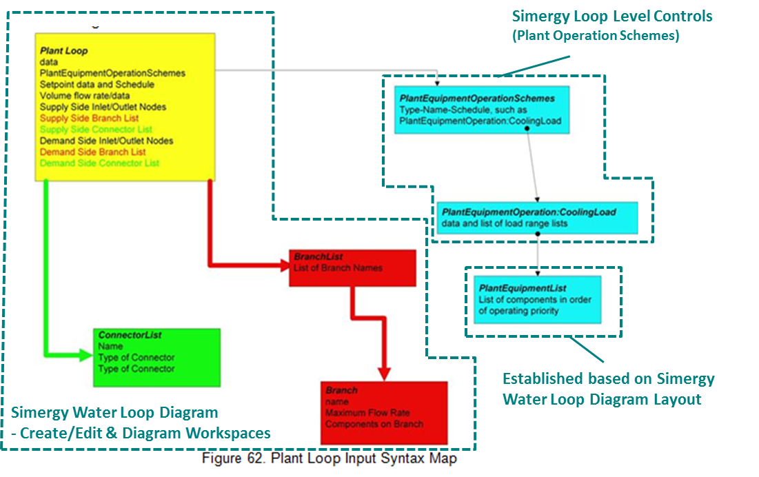
The EnergyPlus objects and fields associated with the water loops within the Group Plant-Condenser Loops are covered in different areas within Simergy. The diagram below is a Plant Loop Input Syntax Map (Note: EnergyPlus differentiates between condenser and other plant loops) from the EnergyPlus v7.1 documentation displaying the different objects, their associated fields, and how they relate to each other within the IDF structure. Overlaid on the diagram is how these areas are covered within Simergy.
The Simergy Water Loop Diagrams (in this case HW, CHW, CW, MxW) provide coverage of a majority of the objects and fields, as shown by two of the three highlighted areas above related to the Water Loop Diagrams. The Simergy capabilities are located in both the Create/Edit and Diagram Workspaces.
By the user dragging and dropping component shapes on the diagramming canvas and linking them together with connectors they are inputting default values for the component fields, they are establishing the branches and connections between the different objects. If a user is in the Water Loop Diagram workspace and selects a Shape Component they will see the input values for a number of the fields listed above shown in the component properties area of the interface.
Note: the user can select System Templates where these connections and relationships have already been established versus having to build them from scratch each time.
The Plant Equipment List is automatically generated, containing all supply side components (except pumps and pipes), based either on the System Template that is selected or the shape components used to build the diagram.
Note: A current limitation within Simergy is that there is not a mechanism to define custom lists, such as introducing multiple Plant Equipment Lists that are contain only a subset of components in a loop.
The Plant Equipment Operation Scheme for EnergyPlus is established by the user in Simergy through the Plant Loop Level Controls.
The location where the user can define overall loop parameters such as the design supply air, loop volume and loop flow depending on if the user is working with the Air Loops or the Water Loops.
The air loop parameters table, beneath the loop diagram view, allows the user to establish overall loop parameters for the following properties. The user can specify a value and associated units.
The options available to the user in the Value column drop down list are - default and autosizing
The options available to the user in the Value column drop down list are the Library Entries for the air loop that have been established for Sizing Params in the Controls and Performance Data section of the ribbon on the Libraries tab.
The water loop parameters table, beneath the loop diagram view, allows the user to establish overall water loop parameters for the following properties. The user can specify a value and associated unit, in addition to a sub-property, value and associated unit.
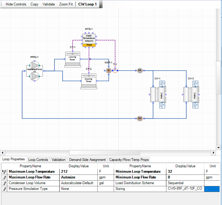
Numerical entry for the maximum loop temperature value
Numerical entry for the minimum loop temperature value
Selection or numerical value entry establishing the maximum flow rate. Selection options include 0-default and autosize.
Selection of 0-Default or numerical value entry establishing the minimum flow rate.
The Plant Loop Volume (m3) numeric field contains the loop volume for the entire loop, i.e. both the demand side and the supply side. In addition, options for 0-Minimum and Autocalculate are provided. The loop capacitance autocalculate option gives reasonable values for most system sizes.
Same as the Plant Loop Volume, but with a name specific to the condenser loop, which is dictated by the structure of EnergyPlus.
The options available to the user in the Value column drop down list are the Library Entries for the water loops (HW, CHW, CW, MxW) that have been established for Sizing Params in the Controls and Performance Data section of the ribbon on the Libraries tab.
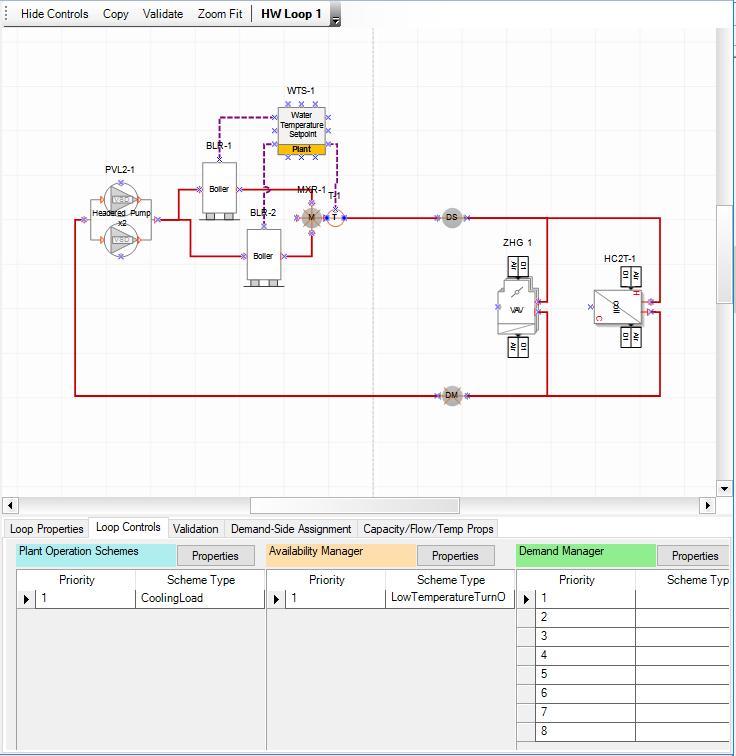
The System Level Controls 'Priority Tables' are included within each loop Diagram workspace. A ‘Priority Table’ provides the users the ability to assign an order for system level controls for availability managers, demand managers, plant operation schemes, and plant availability depending upon what loop diagram is being worked on. The system and loop level control priority tables reside on the diagramming workspace of Air Loops and Water Loops workspaces on the Systems tab. The user will find them in the table below the 2d diagramming canvas. The figure shows the Plant Operation Schemes, Availability and Demand Manager tables shown for the Hot Water Loop.
The table below summarizes which of the five system and loop level control types appear on which Loop Diagram Workspace.
| Loop Workspaces | ||||||
| Loop Level Control Types | Air |
CW |
CHW |
HW |
MxW |
|
| 1 | Plant Operation Schemes (HW, CHW, MxW) | Y |
|
Y |
Y |
Y |
| 2 | Condenser Operation Schemes (CW) |
|
Y |
|
|
|
| 3 | Plant Availability Managers (Water) |
|
Y |
Y |
Y |
Y |
| 4 | Availability Managers (Air) | Y |
|
|
|
|
| 5 | Demand Managers | Y |
Y |
Y |
Y |
Y |
For each of the Loop Level Control type tables shown on a workspace the priority and object type fields are consistently displayed with the exception of the Demand Manager.
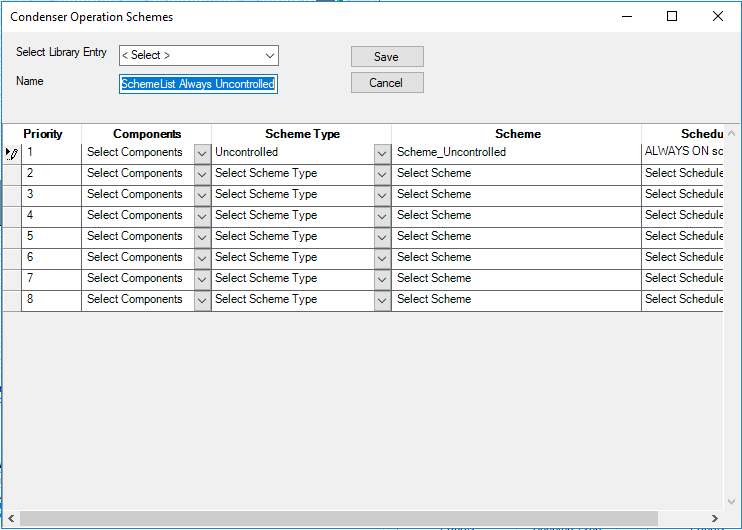
Selecting properties for each of the Loop Level Control types will display a pop-up dialog box showing the properties for that Loop Level Control. The example below is the Condenser Operation Schemes Properties dialog box. Each properties dialog box is discussed in further detail in each Loop Level Control type section.
The following are required controls for a Simergy and EnergyPlus simulation to run:
Plants and condenser loops must have some mechanism for controlling the operation of the loop and which equipment is available under what conditions. Since there may be multiple control schemes that are assigned various priorities associated with each loop, an overall operation scheme must be defined. Each operation scheme must have the type of operation scheme, and the schedule that defines its availability. Operation schemes are listed in "priority" order. Note that each scheme must address the entire load and/or condition ranges for the simulation.
To access the Plant Loop Scheme select Properties. A pop-up dialog box appears and the user can either Select a Library Entry, Select one and make changes or create a new one.
Note: To effectively incorporate any selections made in this dialog box Save must be selected before the dialog box is closed, otherwise the edits will not be saved and will not be shown in the table below the diagramming canvas. After Save is selected the user will be notified by a pop-up message expressing that the information has been saved to the Library.
Once edits have been successfully completed within the properties dialog the summary table on the Diagram Workspace will be updated to show the Object type and the priority number. If more priorities have been defined than can be shown in the allotted space a scroll bar will appear enabling the user to view the full set.
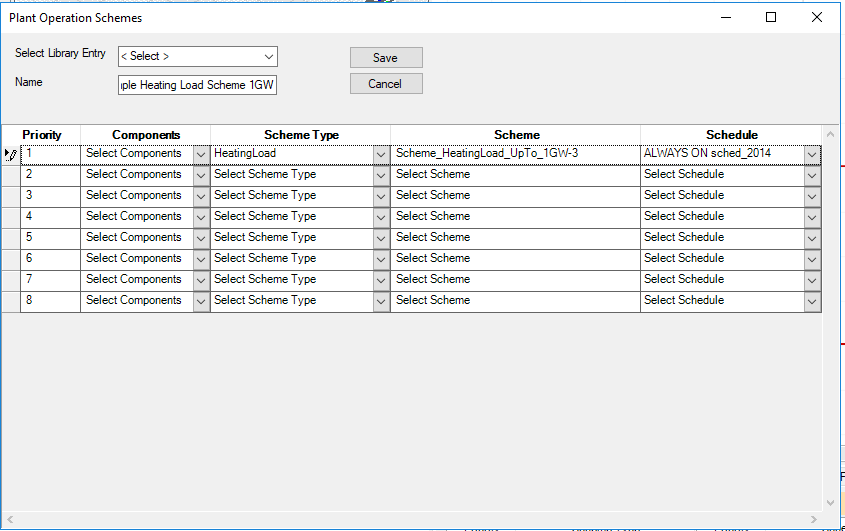
The user can select object types to establish a priority list of one to eight. Note: Inclusion of one priority is required
A drop down list displaying the object type options. See Plant Operation Scheme Object Types Options. Selecting an Object type activates the Scheme drop down list.
The object types include:
Uncontrolled
CoolingLoad
HeatingLoad
OutdoorDryBulb
OutdoorWetBulb
OutdoorDewpoint
ComponentSetpoint
OutdoorRelativeHumidity
OutdoorDryBulbDifference
OutdoorWetBulbDifference
OutdoorDewpointDifference
Once an Object Type is selected the available Scheme options are made available from on the drop down list. When the user selects a scheme type, which can be generated on the Control Schemes workspace within the Controls and Performance Data section of the ribbon on the Libraries tab, the Schedule Name drop down list becomes active.
Provides the user with schedule type selections within the drop down list that when selected are associated with the scheme
Provides the available selections in a drop down list for the current Source Library for the Simergy Model.
A display and text entry box. It provides the name of the selected library and allows the user to edit and re-Save the Library Entry
Allows the user to Save changes to the current Library Entry that is being worked on to the Simergy project.
Allows the user to Save changes to the current Library Entry that is being worked on to the Simergy Source Library.
Allows the user to cancel any changes that have been made that have not been previously saved.
Note: See Plant Operation Schemes description for complete field level descriptions. Only the differences are described here.
The EnergyPlus objects and fields associated with the Condenser Loop within the Group Plant-Condenser Loops are broken out separately within the EnergyPlus documentation, however in Simergy they are handled in a similar fashion to the other water loops and do not warrant a separate description. The main differences between the two are the applicable component names and operation schemes. See Loop Level Control - Plant Operation Schemes.
Note: The object type list is the same as the Plant Operation Scheme Object Types
The selections available in the drop down list are the Library Entries associated with the condenser loop object type that has been selected.
Note: See Plant Operation Schemes description for complete field level descriptions. Only the differences are described here.
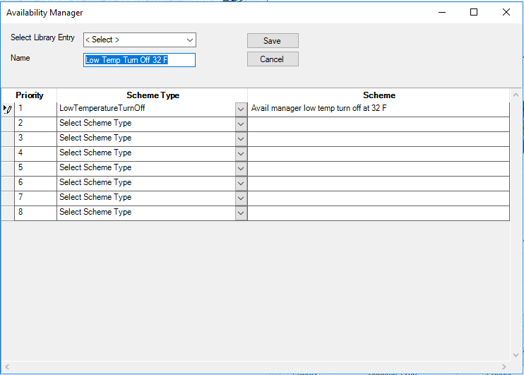
System Availability Managers are one of the high-level control constructs in EnergyPlus. A System Availability Manager is able to access data from any of the HVAC system nodes and use this data to make a decision on whether an entire AirLoopHVAC or PlantLoop should be on or off. System Availability Managers are executed at the start of each HVAC timestep. They reside outside the HVAC system iteration loops. Thus, the System Availability Managers are executed once per HVAC timestep, and they use previous timestep information (except for zone load) to calculate their set points.
The Plant Availability Managers appear on the Diagram Workspace of the water loops. A separate loop level control type is utilized for the availability managers associated with the Air Loops. The dialog box contains the same fields as Plant Operation Scheme Properties. The only difference is the sources of the drop down lists for Object Type and Scheme.
Tip: For the plant loops, there is no precedence among the System Availability Manager status flag values. Instead, the first availability manager giving a status flag value other than No Action sets the status for the loop. The availability managers overrule the fan on/off schedule.
The source of the selections in the drop down list is <add>
The object types are:
Scheduled
ScheduledOn
ScheduledOff
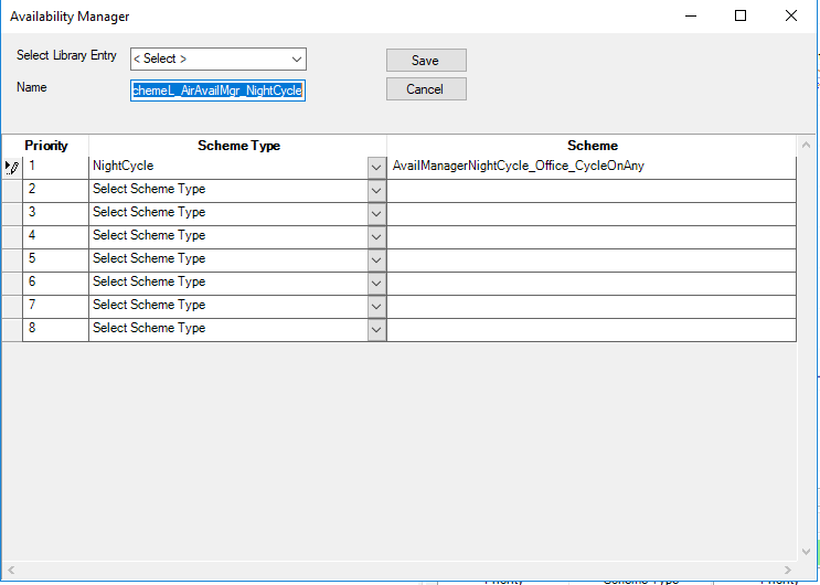
NightCycle
DifferentialThermostat
HighTemperatureTurnOff
HighTemperatureTurnOn
LowTemperatureTurnOff
LowTemperatureTurnOn
NightVentilation
HybridVentilation
The selections available in the drop down list are the Library Entries associated with the object type selected for the water loops. There are library entries packaged with the Simergy installation or they can be created by going to the Libraries/Control Schemes workspace and creating a library entry for the desired Type and Sub Type
Note: See Plant Operation Schemes description for complete field level descriptions. Only the differences are described here.
System Availability Managers are one of the high-level control constructs in EnergyPlus. A System Availability Manager is able to access data from any of the HVAC system nodes and use this data to make a decision on whether an entire AirLoopHVAC or PlantLoop should be on or off. System Availability Managers are executed at the start of each HVAC timestep. They reside outside the HVAC system iteration loops. Thus, the System Availability Managers are executed once per HVAC timestep, and they use previous timestep information (except for zone load) to calculate their set points. Some of the managers monitor the temperature at an air or plant node to determine whether the system should be on or off.
The Availability Managers appear on the Diagram Workspace of the Air Loops. The dialog box contains the same fields as Plant Operation Scheme Properties. The only difference is the sources of the drop down lists for Object Type and Scheme.
The source of the selections in the drop down list is <add>
The object types are the same as the Plant Availability Managers
The selections available in the drop down list are the Library Entries associated with the object type selected for the air loops
Note: See Plant Operation Schemes description for complete field level descriptions. Only the differences are described here.
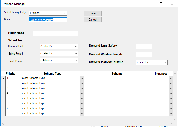
The Demand Manager Properties dialog differs significantly from the other properties dialog boxes. It enables the user to incorporate demand limiting controls, which serve as strategies reduce demand, particularly at peak times, which can save on utility bills. The demand limiting controls (demand managers) either shut off or function to reduce the power to non-essential loads in order to reduce the overall building demand. See EnergyPlus documentation for further detail.
Source: EnergyPlus Documentation for the following field descriptions
This field references the meter that is to be monitored and demand limited. Only electricity meters are currently allowed.
The reference to the schedule object specifying the target demand limits.
Demand Managers in the list are activated based on the Demand Manager Priority. If the Sequential option is used, each manager in the list is activated in sequence from first to last until demand is reduced below the limit or until all managers are activated. If the All option is used, all managers are activated simultaneously to achieve the maximum demand reduction. A Demand Manager is skipped if it cannot reduce the demand. Possible reasons that a manager cannot reduce demand include:
not enough load to limit
not available because of its Availability Schedule
already activated; load limited during a previous timestep.
This field is similar to the field of the same name in the UtilityCost:Tariff object. However, the user may not want to limit using the same demand window as the utility company. This field allows the user to input the number of minutes over which to calculate the current demand. The minutes are rounded to match the nearest multiple of time steps.
The user can select object types to establish a priority list of one to eight. Note: Inclusion of one priority is required
The source of the selections in the drop down list is <add>
The object types are:
Exterior Lights
Lights
Electric Equipment
Thermostats
The selections available in the drop down list are the Library Entries associated with the object type selected for the air loops
______________________________________________________________________________________
© Copyright 2013 Simergy, Sustainable IQ, Inc.