Each of the ~200 component shapes within Simergy have been created so that they will be recognizable by the shape alone to the engineering community and may be similar to shapes that they have used to create system designs for projects. Almost all of the EnergyPlus objects outlined with the Input Data File (IDF) format have a shape associated with them. In some cases one shape, such as the chiller shape, will represent multiple IDF EnergyPlus objects. Since there is no one standard for component shapes a number of sources were references for creating an appropriate shape, such as the ASHRAE Fundamentals Handbook and different engineering design team’s drawing set. In other cases, new shapes were created because shape precedents could not be located. Overall, the intent is that the engineer could describe or review the system design configuration by just looking at the component shapes alone.
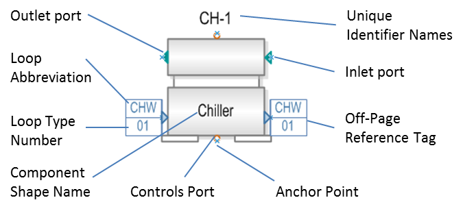
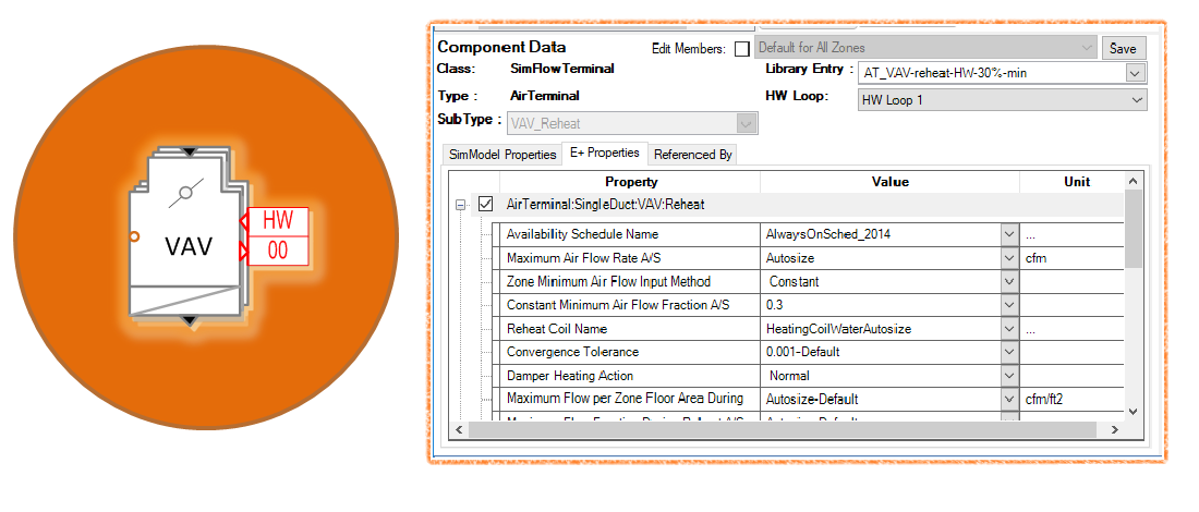
Provides the user another way to easily identify the component in addition to the descriptive shape itself when viewing the overall loop diagram and/or capturing an image of it to use in a report.
The connection points of the component shape to the loop diagram. If fluid is flowing into the shape the user will connect to the inlet.
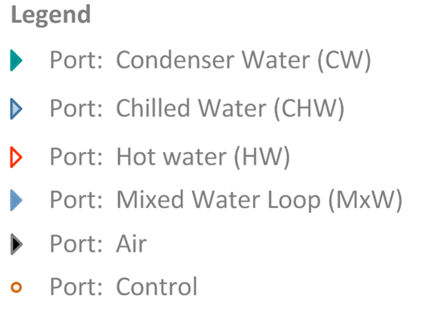
The connection points to the shape from different types of controller objects, such as the Water Temperature Setpoint Controller. Linking a controller to the component through the control port associates the properties of that controller with that component. Port types are differentiated by color and format. The variations are:
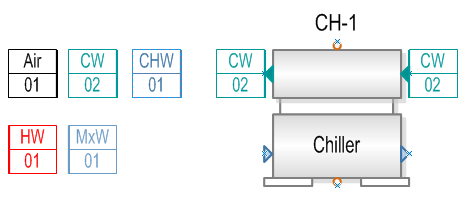
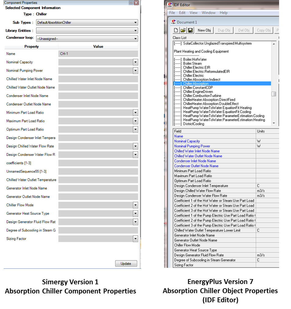
The internal data model names that are provided to each shape when it is first placed on a loop diagram. They allow the user to identify the component across the different loop diagrams as the design gets more complex. In the figure, the Chiller’s unique identifier name is CH-1. If the user goes to the second condenser loop (02), they will find a version of the Chiller shape there with the same name, however the off page reference tags shown on the shape will be chilled water (CHW) tags to express the link back to CHW loop 01.
Off Page References indicate which other loops a component is linked to by the color of the reference tag and the two or three letter Loop Abbreviation, which identifies the loop. The legend and set of tags are:
CW = Condenser Water Loop
HW = Hot Water Loop
CHW = Chilled Water Loop
MxW = Mixed Water Loop
Air = Air Loop
The two digit number in the lower portion of the tag identifies the Loop Type Number the component is linked to. For example the chiller shape shown in the figure is linked to the second condenser loop diagram that has been set up for the project.
Note: Simergy automatically numbers the loops sequentially when they are created by the user, starting with ‘01’.
Allow the user to more easily place the shapes within the HVAC diagramming canvas. The blue x will allow the user to snap to align that point with desired location and place the component shape
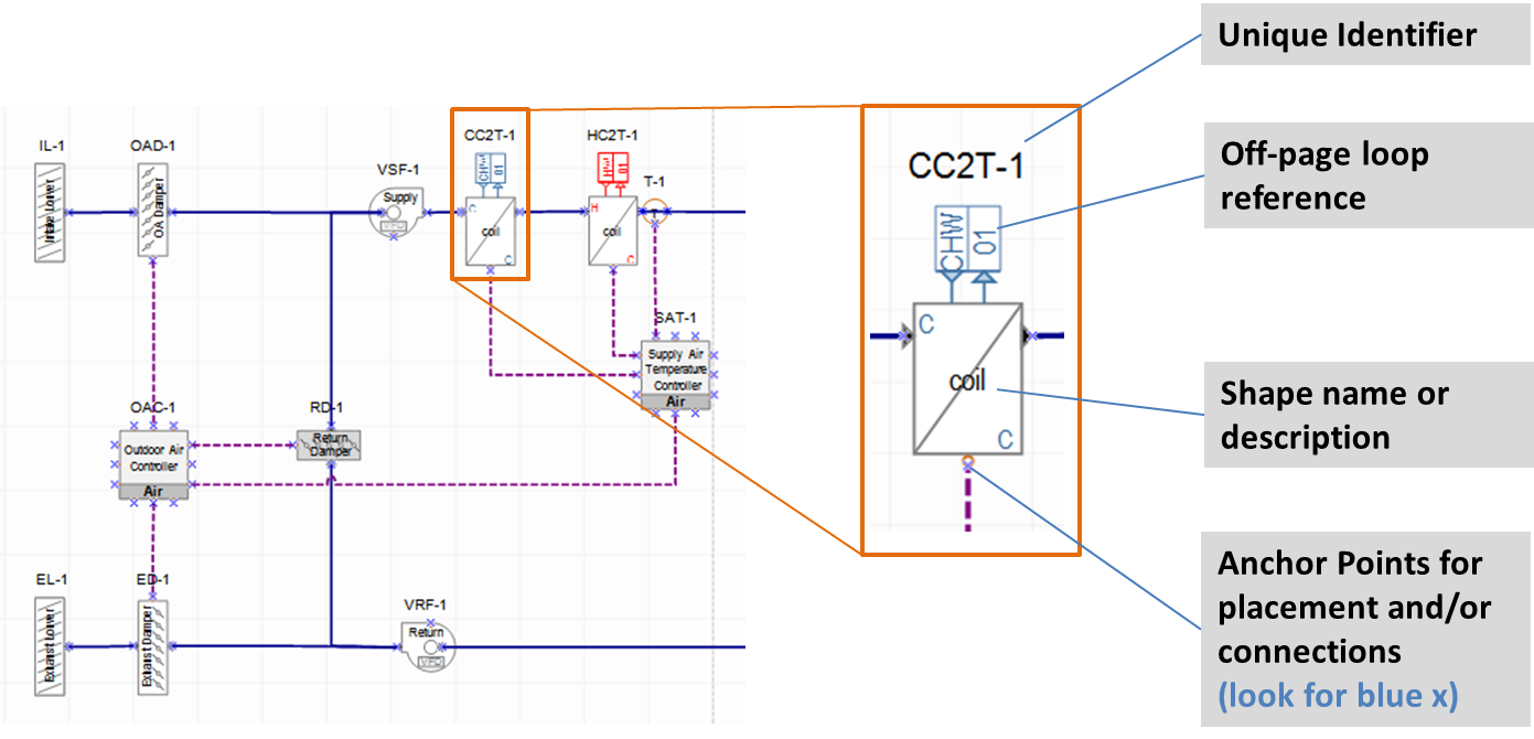
Since component shapes can have off-page loop references, it means that more than one variation of representation is required for these shapes. For example the cooling coil component shape in the image above is shown on the Air Loop. A variation of that component shape will be required to be included on the chilled water loop, and it will need an off-page loop reference tag indicating its connection to the air loop. Therefore depending on the number of sets of ports that a component shape has informs how many variations of that component shape are included in Simergy.
The matrix below provides some examples to explain this point further. The top row shows the base form of some of the component shapes the user will find in Simergy, and the rows below are where component shape variations for the Air Loop and three of the water loop types will be shown (Note: Mixed Water Loop is not included). If a cell is empty it means that a shape component variation is not required.
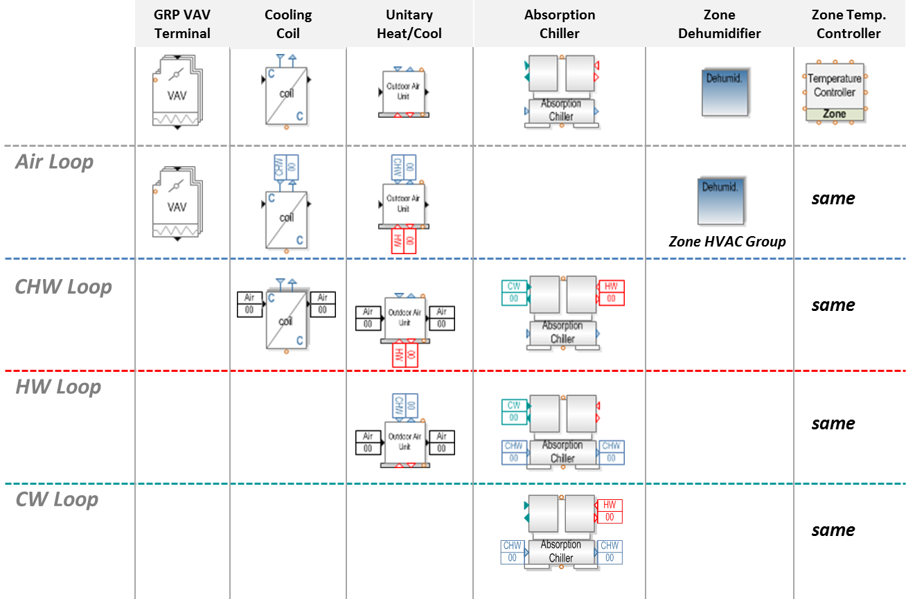
Example 1: the VAV terminal shape only include one set of air ports, so there is only one version of this component shape and it will appear on the Air Loop Stencil.
Example 2: the Cooling Coil discussed previously is shown. The cooling coil has one set of air ports and one set of chilled water ports, so it will have a component shape variation on both the air loop and chilled water loop stencils.
Example 3: the Unitary Heat Cool Component shape has three sets of ports (CW, CHW and HW), therefore it will have component shape variations on those three water loop stencils.
Example 4: the Zone Dehumidifier doesn't have any ports? This is because it is a component shape for Zone Equipment within a Zone HVAC Group. Since the Zone HVAC Groups establish the demand side for the Air Loops it will be displayed on the air loop and will be included on the Zone HVAC Group stencil.
Example 5: the Zone Temperature Controller has twelve (12) control ports, however control ports serve as the exception to the rule of pairs and informing shape variations. The Controller shapes don't have variations, but in this case the Zone Temperature Controller will appear on each Controls and Sensors Stencil for each Loop Type and the Zone HVAC Group.
______________________________________________________________________________________
© Copyright 2013 Simergy, Sustainable IQ, Inc.