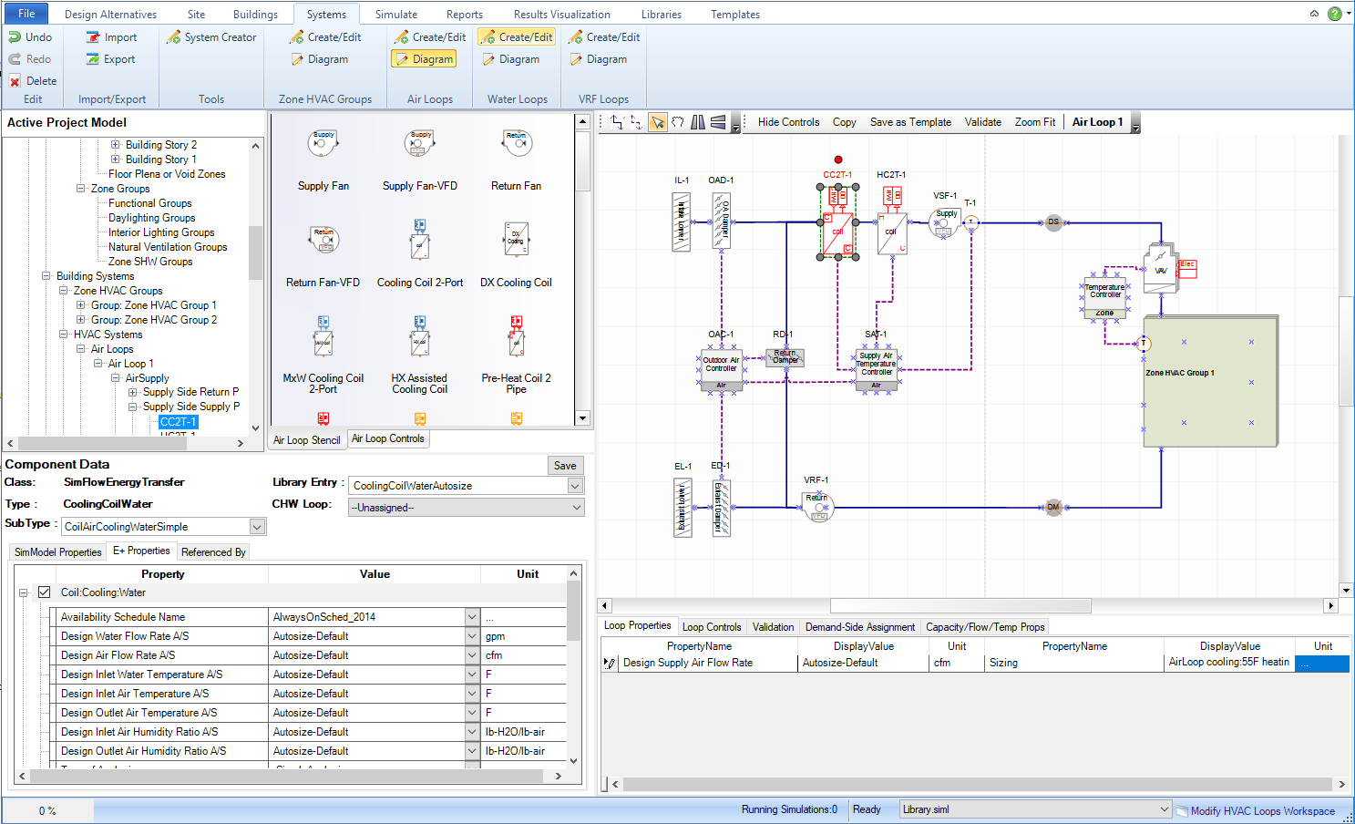
Loop diagrams are configured and viewed on the HVAC Diagramming Canvas, which is a part of four workspaces in the Systems tab and five workspaces in the Template tab.
Note: Zone HVAC Groups are configured on the Zone HVAC Group Canvas.
The HVAC diagramming canvas is divided into two parts by a vertical dashed line down the center. The left side is the loop Supply Side and right side is the Loop Demand Side, which are labeled at the bottom of the canvas.
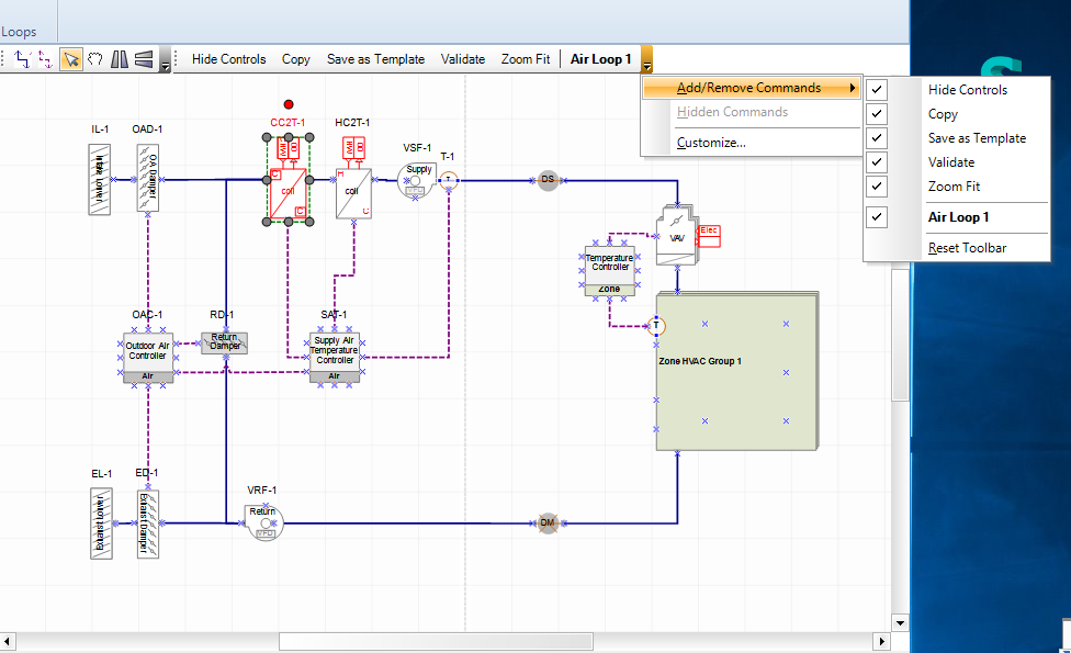
The user has a number of diagramming controls on the top left of the diagramming canvas within a tool bar and five other buttons that are located just below the tool bar
The toolbar contains six (6) features, which can be added or removed as shown on the image above. The toolbar can also be relocated by moving horizontally or it can be undocked and repositioned elsewhere on the HVAC diagramming canvas.
Allows the user to draw a connection between the ports of two component shapes, via the connector, which establishes the relationship between the two components and the loop flow. The component shape connector is shown as a solid blue line.
Allows the user to draw a connection between a controller and a component shape, which establishes the relationship between the controller and the component shape as well as starting to shape the control scheme. The control shape connector is shown as a dashed red line on the HVAC diagramming canvas.
Allows the user to select component shapes and/or connectors. Selecting a single component will highlight the component and trigger the properties to be displayed in the Select Component Information area. The user can also select multiple components by either selecting the component shapes individually while holding down the CTRL button to build the set of multiple components or they can be selected by drawing a fence on the diagramming canvas, which will select all the components (component shapes and connectors) the fence touches.
Tip: To select any component shapes or connectors the pointer tool must be highlighted, so it is a good idea to quickly check that it is highlighted versus other features, such as the connector tool
Allows the user to move the entire canvas to reposition the view without adjusting the scale. In addition to selecting the "hand icon" to activate pan the user will need to "right click" with the mouse, and hold the button down as they use the pan command to move the diagramming canvas to the desired view position.
Becomes active when the user selects a component shape or a set of component shapes. As the feature name describes it allows the user to flip the view of the component shape horizontally.
Becomes active when the user selects a component shape or a set of component shapes. As the feature name describes it allows the user to flip the view of the component shape vertically.
Just below the diagramming toolbar (default location) are (5) diagramming buttons that provide the user powerful viewing, exporting, evaluating and zooming features.
The default representation of the button is "Hide Controls", which means that the controllers, sensors and controls connectors are shown on the HVAC diagramming canvas. When the user selects the button the text representation changes to "Show Controls", the button has a blue outline glow and the controls component shapes and connectors are hidden from the view. The example below for an air loop for an HVAC system design shows both "view states".
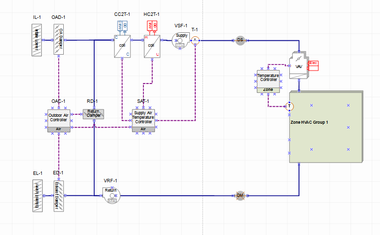
Controls Component Shapes and Controls Connectors are being displayed
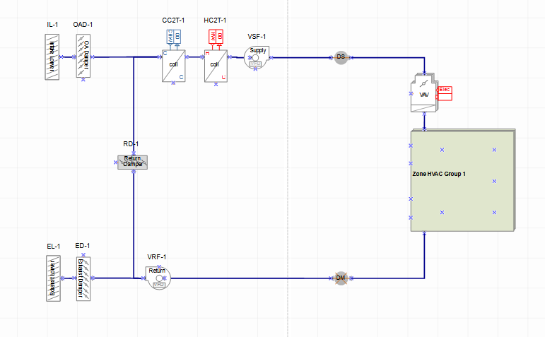
Controls Component Shapes and Controls Connectors are hidden.
Allows the user to capture the loop diagram design currently displayed on the screen to create a new system template for that loop type. In addition, the user can save a copy of the current diagram. If no changes have been made to the diagram and the user selects the button the user is presented with the option "A template with the current design already exists. Do you want to save another copy?". If "Yes" is selected a copy of the current diagram will be saved to the source library with a new default name.
Both of these features eliminate the need for the user to go to the Templates workspace for the loop type to make the changes, they have the capability within this workspace.
Note: this button appears in the Diagram Workspace for Zone HVAC Groups, Air Loops and Water Loops.
Allows the user to capture the loop diagram layout visually and save it. The Simergy diagramming environment utilizes Nevron, so the file types that can be saved with this feature include:
Nevron Drawing Binary (*.ndb) [default]
Nevron Drawing XML (*.ndx)
Nevron Drawing SOAP (*.nds)
Nevron Drawing Custom Binary (*.cndb)
Nevron Drawing Custom XML (*.cndx)
All files (*.*)
Note: this button appears in the Diagram Workspace for Zone HVAC Groups, Air Loops and Water Loops.
Initiates the evaluation of the loop diagram that is currently being viewed compared to the validation rule set(s). When completed the "results" of the validation check can be viewed on the Validation tab of the table directly below the HVAC Diagramming canvas.
Note: Validation can be run in both the Systems Diagram workspaces and the System Templates workspaces.
Tip: It can be very useful to run validation checks at the Zone HVAC Group and Loop Level for Templates rather than waiting to do a validation check at the overall system level. This way potential errors can be identified earlier and there can be less interrogation required at the loop level to determine where the error is.
Resets the view of the HVAC diagramming canvas to the extents of the overall Loop or Zone HVAC Group diagram.
Note: a useful feature to quickly get back to a manageable view for the diagram.
When the extents of the loop diagram are larger then the screen view of the canvas, Scroll Bars will appear allowing horizontal and vertical movement on the canvas.
To dynamically zoom in and out in the 3d view, position the cursor inside the 3d view and then use the mouse wheel to dynamically zoom. Moving the mouse wheel TOWARDS the user ZOOMS OUT and moving the mouse wheel AWAY from the user ZOOMS IN.
______________________________________________________________________________________
© Copyright 2013 Simergy, Sustainable IQ, Inc.