The Systems tab within Simergy contains a number of different workspace types. The sections provide a screenshot (a visual) of the workspace, which highlights the main workspace capability areas, and a portal to descriptions (the detail) of the capability sections. The workspace list is expressed as the ribbon section and then the workspace area name. In this case each listing on the ribbon presents a slightly different workspace, results in eight main workspaces on the Systems tab (including the common Import and Export workspaces)
|
||
|
|
|
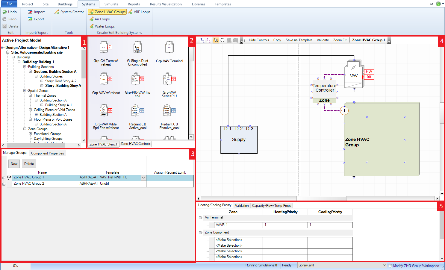
The workspace where users can define Zone HVAC Groups, associate thermal zones with the Zone HVAC Groups and assign Zone HVAC Equipment templates to the Zone HVAC Groups to define the demand side for the air loops.
Main workspace areas:
Project/Component Tree (top left) - allows the user to select single or multiple thermal zones and add them to a Zone HVAC Group by dragging and dropping them on the targeted Zone HVAC Group name.
HVAC diagramming stencils - Zone HVAC Stencil and Zone HVAC Controls & Sensors stencils are both options to the user and they are made active by just selecting on the stencil title. The Zone HVAC stencil is the default and shows icons with titles to describe the available Zone HVAC equipment that can be incorporated into the Zone HVAC Group. Shape components can be selected from the Stencil and then dragged and dropped on the HVAC diagramming canvas to be incorporated into the Zone HVAC Group. Each shape component has anchor points, which assist placing the shape components. Those anchor points will snap to the anchor points (blue x) that are located within the Zone HVAC Group shape and indicate a maximum number of shape components that can be associated with a Zone HVAC Group.
Zone HVAC
Groups (bottom left) - allows the user to define what every
Simergy model must have, at least one Zone HVAC Group. Unlimited
Zone HVAC Groups can be added to the model by selecting New. For
each Zone HVAC Group the user can add single or multiple thermal zones
by dragging and dropping the thermal zones from the Project/Component
Tree. Once a Zone HVAC Group has one thermal zone associated
with it, then the template column becomes active and the user can
select from the available templates in the drop down list or they
can create there own. Selecting a template establishes the demand
side configuration for this Zone HVAC Group within the Air Loop. Tip: The Zone HVAC Group that is selected will be the
Zone HVAC Group template displayed in the Diagram Workspace
Selected
Component Information - when the user selects a component
from the HVAC diagramming canvas, that component's property information
will appear in this field. The type of properties displayed
will vary significantly component to component, however the line items
shown above the table are common fields. For those users that
are familiar with the Input Data File (IDF) structure, the property
list for each component is aligned with that list. For each component
Type, Sub Types and Library Entities will be shown, while shapes that
contain off-page reference tags will potentially have up to four additional
line items for each of the water loop types (HW, CHW, MxW, CW). Tip: Make sure a component has a Library Entity specified,
otherwise the BEM will not simulate.
HVAC diagramming canvas - paints the picture of the components, sensors and controls associated with the Zone HVAC Group. The Zone HVAC Group can be validated and a number of other capabilities are at the users fingertips (think tip of the iceberg).
System Level Controls/ Validation -This field has tabs for setting the heating/cooling priority and a second tab for displaying validation findings. The user can set the heating and cooling priority for air terminals and zone equipment separately. When equipment is added to the Zone HVAC Group the name of the component will automatically be added to the table. To set the priority the user must select the priority number for both heating and cooling from the drop down list. If the user selects Validate on the HVAC diagramming canvas the validation results (name, system issue to be fixed, and error type) will be displayed on the Validation tab.
The workspace allows the user to set up a single or multiple air loops by selecting an Air Loop Template (defining supply side) and assigning Zone HVAC Groups (defining demand side) to them. Once these templates have been assigned then the user can visualize the Air Loop Diagram and they can assign system parameters as well.
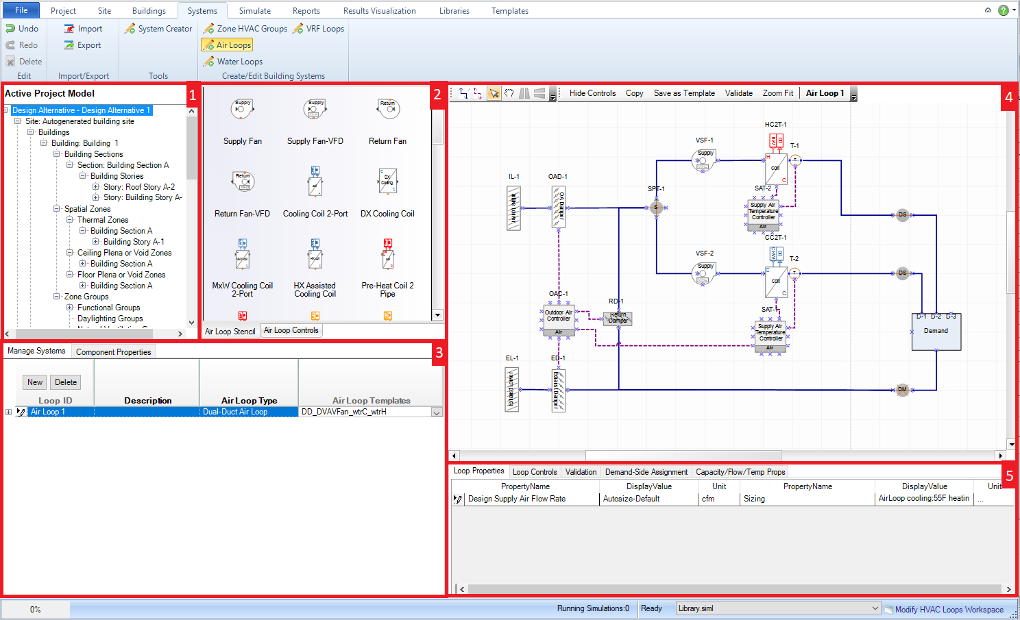
Main workspace areas include:
Project/Component Tree (top left) - Zone HVAC Groups can be highlighted and then dragged and dropped onto the Air Loop ID name to assign those Zone HVAC Groups to the Air Loop. Once that has been done the Zone HVAC Group diagrams will be shown on the demand side of the Air Loop.
HVAC diagramming stencils - Air Loop Stencil and Air Loop Controls & Sensors stencils are both options to the user and they are made active by just selecting on the stencil title. The Air Loop stencil is the default and shows icons with titles to describe the availableAir Loop equipment that can be incorporated into the Air Loop. Shape components can be selected from the Stencil and then dragged and dropped on the Air Loop diagramming canvas to be incorporated into the Air Loop. Each shape component has anchor points, which assist placing the shape components. Those anchor points will snap to the anchor points (blue x) that are located within the Air Loop shape and indicate a maximum number of shape components that can be associated with an Air Loop.
Air System
Groups (bottom left) - allows the user to build or delete
single or multiple air loops. The supply side and demand side
need to be established to set up the Air Loop. The Supply side
can be established by selecting an Air Loop Template from the drop
down list in that column. The Air Loop Template could just serve
as the starting point for the loop design that can then be edited
in the Diagram workspace. The demand side is defined by applying
the Zone HVAC groups to the Air Loop, which can be done by dragging
and dropping them from the Project Component Tree. Once a Zone
HVAC Group is applied the default Demand Side Shape is replaced with
the Zone HVAC Group diagram.
Selected
Component Information (Properties) - when the user selects
a component from the HVAC diagramming canvas property information
will appear in this field. The type of properties displayed
will vary significantly component to component, however the line items
shown above the table are common fields. For those users that
are familiar with the Input Data File (IDF) structure, the property
list for each component is aligned with that list. For each component
Type, Sub Types and Library Entities will be shown, while shapes that
contain off-page reference tags will potentially have up to four additional
line items for each of the water loop types (HW, CHW, MxW, CW). Tip: Make sure a component has a Library Entity specified,
otherwise the BEM will not simulate.
HVAC diagramming canvas - paints the picture of the Air Loop Design for the supply and demand side based on the templates that have been applied. The user can view other Air Loop Designs by selecting a different Air Loop from the Air Loop Groups. In addition the user can choose to hide the controls to display a simpler loop design picture or show the controls to get the complete picture. The only thing the user can't do is select components and start editing the loop design. To do that they need to go to the Diagram Workspace. Tip: the Zoom to Fit button can be very useful when the user is investigating different aspects of the Air Loop design.
Air System Parameters (bottom right) - allows the user to set parameters, such as sizing criteria, at the overall Air Loop level.
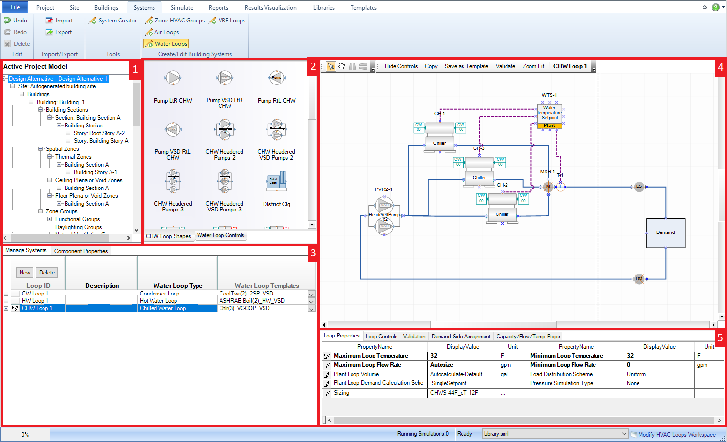
Main workspace areas include:
Project/Component Tree (top left) - Zone HVAC Groups can be highlighted and then dragged and dropped onto the Air Loop ID name to assign those Zone HVAC Groups to the Air Loop. Once that has been done the Zone HVAC Group diagrams will be shown on the demand side of the Air Loop.
Water Loop Diagramming stencils - Water Loop Stencil and Water Loop Controls & Sensors stencils are both options to the user and they are made active by just selecting on the stencil title. The Water Loop stencil is the default and shows icons with titles to describe the available Water Loop equipment that can be incorporated into the Water Loop. Shape components can be selected from the Stencil and then dragged and dropped on the Water Loop diagramming canvas to be incorporated into the Water Loop. Each shape component has anchor points, which assist placing the shape components. Those anchor points will snap to the anchor points (blue x) that are located within the Water Loop shape and indicate a maximum number of shape components that can be associated with an Water Loop.
Water
System Loops (bottom left) - allows the user to create
or delete single or multiple water loops. The user can create
Hot Water, Chilled Water, Condenser Water or Mixed Water Loops by
selecting New. The user can then select a Water Loop Template
from the available selections or go to the Templates tab to create
their own. Once a template has been applied the
supply side of the water loop will be displayed on the HVAC diagramming
canvas with the demand side demand box shape placeholder. The
demand side will appear once the water loops have been assigned to
the components with off-page references that are included in the other
loops. The user can view different water loops by selecting
on the different water loops.
Selected
Component Information (Properties) - when the user selects
a component from the HVAC diagramming canvas property information
will appear in this field. The type of properties displayed
will vary significantly component to component, however the line items
shown above the table are common fields. For those users that
are familiar with the Input Data File (IDF) structure, the property
list for each component is aligned with that list. For each component
Type, Sub Types and Library Entities will be shown, while shapes that
contain off-page reference tags will potentially have up to four additional
line items for each of the water loop types (HW, CHW, MxW, CW). Tip: Make sure a component has a Library Entity specified,
otherwise the BEM will not simulate.
HVAC diagramming canvas - paints the picture of the Water Loop Design for the supply and demand side based on the templates that have been applied. The user can choose to hide the controls to display a simpler loop design picture or show the controls to get the complete picture. The only thing the user can't do is select components and start editing the loop design. To do that they need to go to the Diagram Workspace.
Water System Parameters (bottom right) - allows the user to set parameters, such as sizing criteria, at the overall Water Loop level.
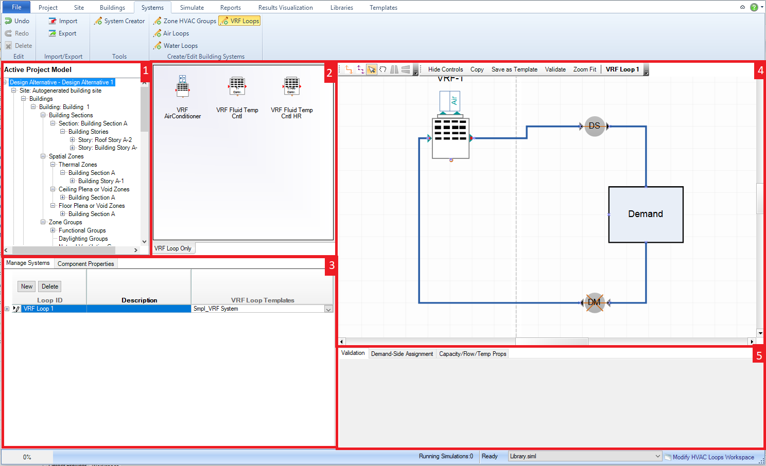
Main workspace areas include:
Project/Component Tree (top left) - Zone HVAC Groups can be highlighted and then dragged and dropped onto the Air Loop ID name to assign those Zone HVAC Groups to the Air Loop. Once that has been done the Zone HVAC Group diagrams will be shown on the demand side of the Air Loop.
VRF Loop Diagramming stencils - VRF Loop Stencil and VRF Loop Controls & Sensors stencils are both options to the user and they are made active by just selecting on the stencil title. The VRF Loop stencil is the default and shows icons with titles to describe the available VRF Loop equipment that can be incorporated into the WaVRF ter Loop. Shape components can be selected from the Stencil and then dragged and dropped on the VRF Loop diagramming canvas to be incorporated into the VRF Loop. Each shape component has anchor points, which assist placing the shape components. Those anchor points will snap to the anchor points (blue x) that are located within the VRF Loop shape and indicate a maximum number of shape components that can be associated with an VRF Loop.
VRF
System Loops (bottom left) - allows the user to create
or delete single or multiple water loops. The user can create
Hot Water, Chilled Water, Condenser Water or Mixed Water Loops by
selecting New. The user can then select a Water Loop Template
from the available selections or go to the Templates tab to create
their own. Once a template has been applied the
supply side of the water loop will be displayed on the HVAC diagramming
canvas with the demand side demand box shape placeholder. The
demand side will appear once the water loops have been assigned to
the components with off-page references that are included in the other
loops. The user can view different water loops by selecting
on the different water loops.
Selected
Component Information (Properties) - when the user selects
a component from the HVAC diagramming canvas property information
will appear in this field. The type of properties displayed
will vary significantly component to component, however the line items
shown above the table are common fields. For those users that
are familiar with the Input Data File (IDF) structure, the property
list for each component is aligned with that list. For each component
Type, Sub Types and Library Entities will be shown, while shapes that
contain off-page reference tags will potentially have up to four additional
line items for each of the water loop types (HW, CHW, MxW, CW). Tip: Make sure a component has a Library Entity specified,
otherwise the BEM will not simulate.
HVAC diagramming canvas - paints the picture of the Water Loop Design for the supply and demand side based on the templates that have been applied. The user can choose to hide the controls to display a simpler loop design picture or show the controls to get the complete picture. The only thing the user can't do is select components and start editing the loop design. To do that they need to go to the Diagram Workspace.
VRF System Parameters (bottom right) - allows the user to set parameters, such as sizing criteria, at the overall Water Loop level.
Main Workspace areas include:
Project/Component Tree (top left) - to change the Air Loop Diagram that is being worked on in the Diagram workspace, the user can select the desired Air Loop from the tree, right click, and select Diagram Air Loop.
Interactive 3d Model View (middle top) - provides the user a 3d interactive view of the current model to preview site objects that are being and/or have been created
Template Selection Palette- Here the user can select templates for each of the various types of system loops and groups. The selection of system and group templates can be saved as a named "super template" to make applying that specific system and group setup to another model quick and painless. There are also controls to generate the current selection of systems and groups in the current model or to delete all systems and groups in the current model to start from scratch.
System Creator Preview Diagram - this palette displays an interactive diagram showing the systems that will be generated based on the current selections. The user can rename, resize and drag the system markers to visualize the whole network of systems and groups before generating them within the model.
______________________________________________________________________________________
© Copyright 2013 Simergy, Sustainable IQ, Inc.