Workspace: Systems/ ZoneHVAC Groups/Create-Edit and Systems/ ZoneHVAC Groups/Diagram
Workspace Area Links
To set Zone HVAC Groups for a BEM the user will need to complete a few steps within the Credit/Edit workspace. The user may not need to go to the Diagrams Workspace. If the user selects a template and they do not need to edit the Zone HVAC template by either changing a component, editing the component properties or utilizing other features in the Diagram Workspace. The features within each workspace are described in greater detail below as well as the steps involved in a typical workflow.
When a user has assigned a thermal zone to a Zone HVAC Group, the letters (HG) will appear at the end of the thermal zone listing on the Project Tree.
The main workspace areas are described here.
For each BEM a user must setup at least one Zone HVAC Group that contains thermal zones. One approach to setting up the Zone HVAC Groups is:
Creates a new Zone HVAC Group and a new row in the table
The selected row is deleted along with the ZoneHVAC Group and the previous information that had been assigned to it.
A default name is assigned in sequential order starting with Zone HVAC Group-1, which can be changed by the user
Users can assign thermal zones to Zone HVAC Groups by highlighting individual thermal zones and/or multiple thermal zones (holding down CTRL key) in the Active Project Model Tree and then drag and drop them to the desired Zone HVAC Group. After completing the 'drag and drop' the names of the thermal zones will appear in the rows below the Zone HVAC Group.
The user can select a Zone HVAC Group Template from the drop down list to associate with the Zone HVAC Group and to establish what will be the demand side for the Air Loop. The selections available depend on what is available in the Source Library. The user can create Zone HVAC Groups Templates in the Templates Workspace.
Allows the user to assign the energy contribution of Zone HVAC equipment to surfaces in the BEM.
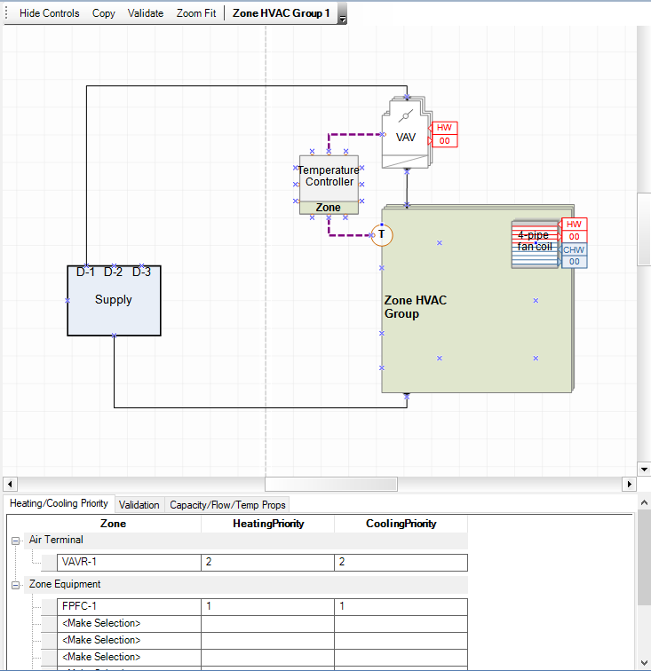
Once a template has been selected the diagram for the Zone HVAC Group is displayed in the 2d view and the Air Terminals and other Zone Equipment that are included in the Zone HVAC Group are automatically displayed in the first column. In the example below the Air Terminal, a VAV with reheat (VAVR-1), is included in the table as well as the Four Pipe Fan Coil (FPFC-1), which is displayed under Zone Equipment.
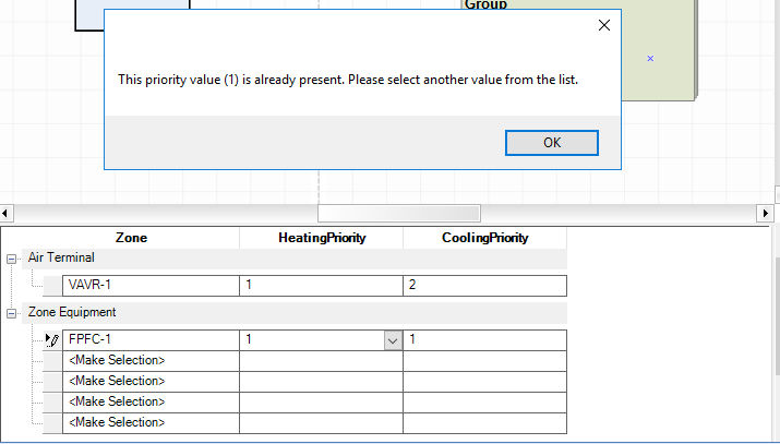
If more than one type of equipment (including both Air Terminals and Zone Equipment) is included within a Zone HVAC Group the user is required to establish the heating priority for that equipment set. Each cell in the column contains a drop down list that allows the user to select the priority for the specific equipment. Different types of equipment cannot have the same priority number. In the example below we tried to set the VAV to heating priority 1 in addition to the four pipe fan coil unit, and we received an error message notification. If we wanted to change the order we could select FPFC-1 and change to either blank (0) or select a lower number. Then we could change the VAVR-1 to a 1 priority.
If more than one type of equipment (including both Air Terminals and Zone Equipment) is included within a Zone HVAC Group the user is required to establish the cooling priority for that equipment set. Each cell in the column contains a drop down list that allows the user to select the priority for the specific equipment. Different types of equipment cannot have the same priority number.
If the user selects Validate and there are issues with the Zone HVAC Group set up, the Validation tab will be come to the front and the issues will be displayed in a table format. If there are no issues related to the Validation Rule Set, the user will receive the message "Validation run successful and did not find any errors with your system configuration".
The main workspace areas are described here.
If the user has gone to the Diagram workspace there any of a number of things they could potentially interested in doing that don't require a specific order. Some of the common tasks with links to detailed descriptions include:
The user can select shapes from the Zone HVAC stencil and then drag and drop the component shapes onto the Zone HVAC Group 2d canvas. For Air terminals they will most likely need to draw or edit connectors.
The user can select shapes from the Zone HVAC Controls Sensors Stencil and then drag and drop the controls component shapes onto the Zone HVAC Group 2d canvas. For Controllers users will most likely need to draw or edit connectors.
The user needs to select the desired component shape in the 2d view and then go to the Component Information properties and select a different Sub Type from the drop down list.
The user needs to select the desired component shape in the 2d view and then go to the Component Information properties and select a Library Entity from the drop down list. The user can also change the Source Library to access other Library Entity options from different Source Libraries.
The user needs to select the desired component shape in the 2d view and then go to the Component Information properties and select a water loop type from the drop down list.
The Zone HVAC Groups can be reconfigured in a number of ways using the Zone HVAC Group 2d canvas tools.
If more than one type of equipment (including both Air Terminals and Zone Equipment) is included within a Zone HVAC Group the user is required to establish the heating and cooling priority separately for that equipment set. Each cell in the column contains a drop down list that allows the user to select the priority for the specific equipment. Different types of equipment cannot have the same priority number.
______________________________________________________________________________________
© Copyright 2013 Simergy, Sustainable IQ, Inc.