Location = Templates/System Templates/Zone HVAC Groups
The Zone HVAC Groups workspace is broken down into five main areas described in the System Templates Workspace, and is very similar in composition and capabilities to the Zone HVAC Groups Create & Edit Workspace. The user can work with the Zone HVAC Groups in a number of ways. They can:
The following provide more detailed information for the main workspace areas, and the features and fields within those areas.
System Template Naming/Selection Area - select different templates to view, edit or copy from the drop down list or name and save new ones
Component Properties - displays all of the properties associated with the component that has been selected in the HVAC Diagramming canvas
Stencils - the different types of components and control and sensor shapes that can be dragged and dropped onto the HVAC diagramming canvas to create a Zone HVAC Group
HVAC Diagramming Canvas - where the Zone HVAC Group can be assembled by dragging and dropping component shapes from the stencils and utilizing the diagramming tools to connect and configure the Zone HVAC group
Zone HVAC Group Controls - sets the heating and cooling priority for the zone equipment, so that EnergyPlus has a guide for how the zone equipment should be utilized
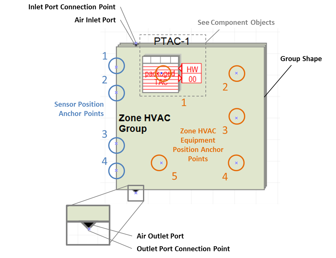
The Zone HVAC Group Shape has a number of important parts, which are highlighted in the diagram below:
The image below is an example of what a more complex Zone HVAC Group Template can begin to look. It incorporates an air terminal, four types of zone HVAC equipment (Ideal Loads, Energy Recovery Ventilator, Lightweight radiant ceiling panels and Lightweight Radiant Floor Panels) and four sensor types (temperature, pressure, daylight, relative humidity). The default properties for each component can be reviewed and changed by selecting on the component shapes and reviewing the properties that are shown in the lower left corner of the Zone HVAC Group Workspace.
Zone HVAC Group Setup provides an explanation of the additional process steps required, such as establishing the priority sequence for the Zone HVAC equipment.

The figure below shows a Zone HVAC Group template on the HVAC Diagramming canvas. There are a number of tools in the ribbon across the top that provide a range of capabilities.
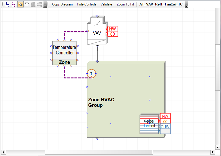
Select when you want to draw a connection between a component, such as an air terminal or plenum, to the Zone HVAC Group shape. The connector typically is drawn from the outlet of one component shape to the inlet of another. In the example above the VAV Air Terminal is connected to the Zone HVAC Group by an air connector.
Note: Once selected the Air Connector will remain active until it is deselected. Also if zone equipment, such as the 4-pipe fan coil shown above, is included in the main Zone HVAC Group, no connectors are required to be drawn for those components.
Select when you want to draw a connection between a controller, such as an the Zone Temperature Controller above, to a component control, Zone HVAC Group sensor or other. The connector typically can be drawn from any of the nodes on the controller component shape to any of the nodes on the component or sensor.
Note: Once selected the Air Connector will remain active until it is deselected.
Can be used to select any of the components on the HVAC diagramming canvas. By selecting a component the associated properties will be displayed in the Selected Component Information area of the workspace.
Allows you to move and reposition the diagram within the workspace. You can also use the scroll bars at the bottom and on the right side.
Allows you to reconfigure a selected shape and flip it horizontally.
Allows you to reconfigure a selected shape and flip it vertically.
Allows you to make a copy of the current diagram to the clipboard that can then be pasted into another document.
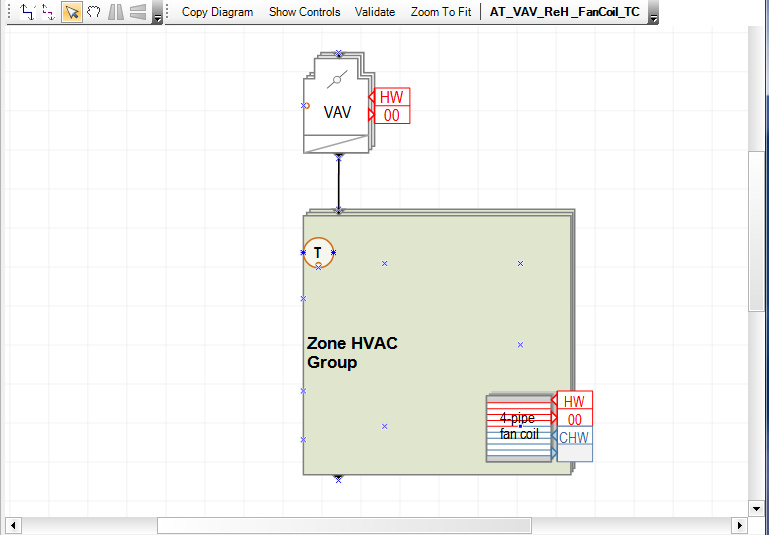
When selected all the controllers and control connectors are hidden. See the result below for the example above. It is a way to simplify the diagram representation if you are working on complex templates.
Runs the Zone HVAC Group validation rule set to assess if there are any problems with the configuration. The results are displayed in the workspace area directly below the HVAC diagramming canvas.
Allows you to easily go back to a view of the HVAC diagramming canvas that is the extents of the overall Zone HVAC Group.
Displays the name of the active Zone HVAC Group Template
The table displays the Zone HVAC Group System Templates that are included with version 1, and provides the full name of the template. The Zone HVAC Group templates utilize a naming convention, so that the names can be represented in an abbreviated manner.
Air System Templates |
Full Name & Description |
| ASHRAE-AT_PFPB_ReH-Elec | |
| ASHRAE-AT_Unctrl | |
| ASHRAE-AT_VAV_NoReH_TC | ASHRAE system type required inputs for a Variable Air Volume Air Terminal with NO Reheat that is Temperature Controlled |
| ASHRAE-AT_VAV_ReH-Elec-PFPB | |
| ASHRAE-AT_VAV_ReH-Wtr_TC | ASHRAE system type required inputs for a Variable Air Volume Air Terminal with with Hot Water Reheat that is Temperature Controlled |
| ASHRAE-PTAC | ASHRAE system type required inputs for a Packaged Terminal Air Conditioner (compound equipment) |
| ASHRAE-PTHP | ASHRAE system type required inputs for a Packaged Terminal Heat Pump (compound equipment) |
| AT_4PipeInduction_Active | An Air Terminal that is an active four pipe induction unit |
| AT_4PipeInduction_Passive | An Air Terminal that is a passive four pipe induction unit |
AT_CooledBeam_Active |
An Active Cooled Beam (chilled beam) Air Terminal |
AT_CooledBeam_Passive |
A Passive Cooled Beam (chilled beam) Air Terminal |
| AT_PFP_Elec_TC | A Parallel Fan Powered Variable Air Volume Air Terminal with an Electrical Reheat coil that is temperature controlled. |
| AT_PFP_Wtr_TC | A Parallel Fan Powered Variable Air Volume Air Terminal with a Hot Water Reheat coil that is temperature controlled. |
AT_Unctrl |
An Uncontrolled Air Terminal |
AT_Unctrl_DSP |
|
AT_Unctrl_SSP |
|
AT_VAV_No-ReH_Dsupp_TC |
A Variable Air Volume Air Terminal with NO Reheat that is temperature controlled and supplied by a dedicated supply plenum group |
AT_VAV_No-ReH_TC |
A Variable Air Volume Air Terminal with NO Reheat that is temperature controlled |
AT_VAV_ReH_FanCoil_TC |
A Variable Air Volume Air Terminal with a Hot Water Reheat coil that is temperature controlled. A four pipe fan coil that connects to a hot water loop and chilled water loop is included as zone equipment. |
AT_VAV_ReH-Elec_TC |
|
AT_VAV_ReH-Gas_TC |
|
AT_VAV_ReH-Wtr_TC |
A Variable Air Volume Air Terminal with Hot Water Reheat that is temperature controlled |
AT_VAV-reheat-water-30%-min |
A Variable Air Volume Air Terminal with Hot Water Reheat that is temperature controlled and has the Constant Minimum Air Flow Fraction set to 30% |
EnergyRecoveryVentilator |
EnergyRecoveryVentilator (compound equipment) |
Ideal |
Ideal System (compound equipment) |
PTAC |
Packaged Terminal Air Conditioner (compound equipment) |
PTHP |
Packaged Terminal Heat Pump (compound equipment) |
RadSlab_Clng_CV |
|
RadSlab_Clng_VAV |
Radiant Slab ceiling with a Variable Air Volume Air Terminal |
RadSlab_Floor_CAV |
|
RadSlab_Floor_VAV |
Radiant Slab floor with a Variable Air Volume Air Terminal |
RadSlab_Floor_VAV+Reheat-HW_30%min |
|
RadSlab_Flr-Clng_VAV |
Radiant Slab floor and ceiling with a Variable Air Volume Air Terminal |
Unit Ventilator |
Unit Ventilator |
WindAC |
Window Air Conditioner |
______________________________________________________________________________________
© Copyright 2013 Simergy, Sustainable IQ, Inc.