The Building workspace enables the user to create/refine geometry, create zones, and establish zone grouping related to all three of the main geometry workflows, which include 1) Defining Building Geometry within Simergy; 2) Defining Building Geometry in Simergy by tracing over 2d plans; 3) Importing an IFC Concept Design BIM Model View Definition model.
The Ribbon includes four sections:
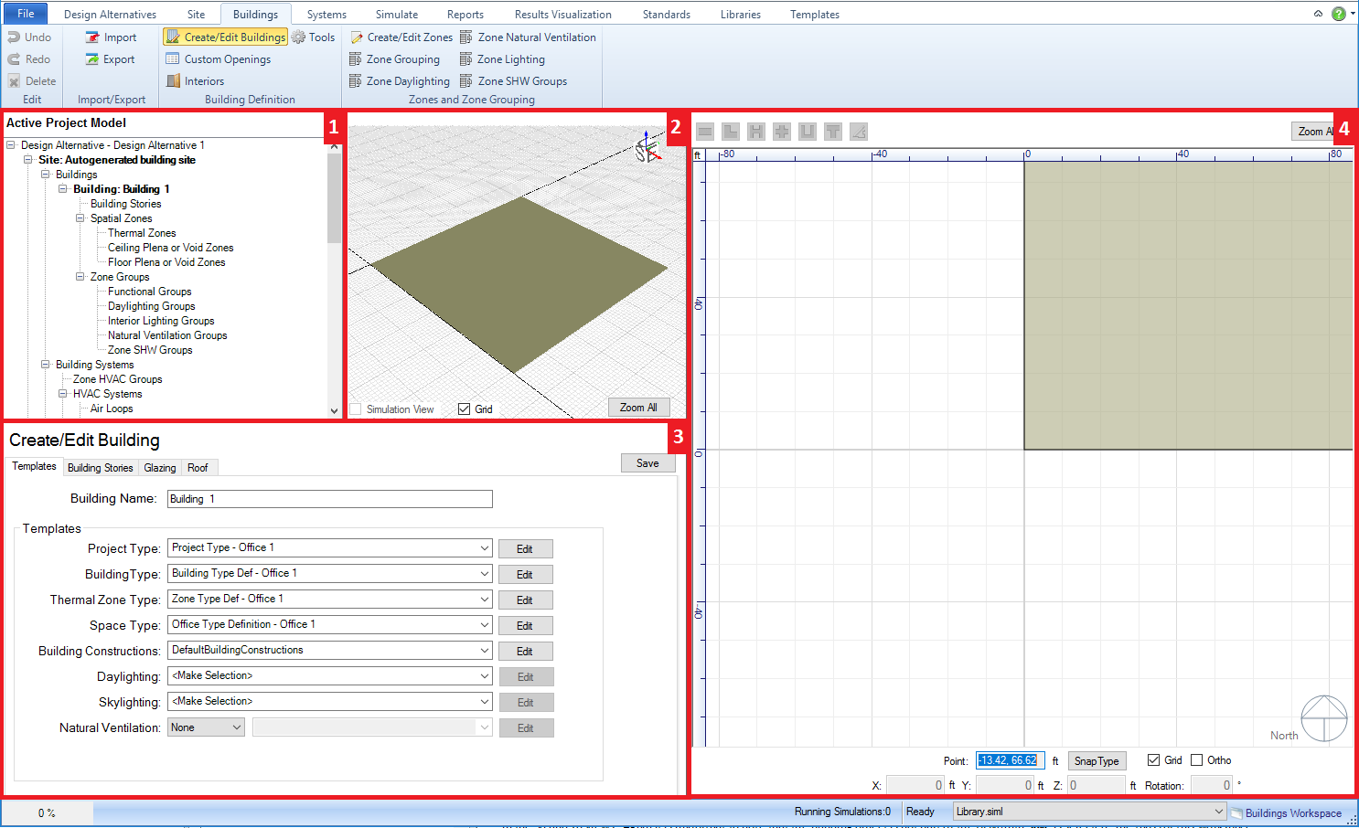
The workspace where users can create and edit BEM geometry at the overall building form level down to the individual window.
The Workspace is comprised of four areas:
Project/Component Tree (top left) - allows the user to see the connections of different components for the project. Serves more as a tool to review connections versus a tool that enables the simulation workspace
Interactive 3d Model View (middle top) - provides the user a 3d interactive view of the current model to preview objects that are being and/or have been created.
Create/Edit Building Stories - the main control center for developing, managing and editing geometry for the BEM. Similar to the Site Workspace the process of geometry creation starts when the user selects "New". The next important step is choosing the Shape. If one of the standard shapes is selected then the user continues completing the inputs in this field, however if Free Form is selected from the drop down list then the user will be drawing the custom geometry within the 2d view, either on a blank canvas or tracing over a 2d DWG/DXF drawing. Numerous other inputs are available related to positioning the building form, establishing the overall height and floor by floor heights and components, zone and plenum configurations and building constructions. And that is just for the Building Stories tab. The following provide additional detail on the different tabs available. Once the user has set the desired inputs (or even if they just want to get a visual of where they are at) they can check the preview model in the 3d and 2d views that updates automatically as changes are made in the various tabs. Again it is important to note that the building object is not part of the BEM until Save is selected. The tabs for this workspace area include Templates, Building Stories, Glazing, Roof and other workspaces selected from the ribbon allow you to make further changes and customizations to the model: Custom Openings, Interiors, and Tools
Overall 2d View (right) - displays the 2d view of the base floor plan or any of the available floor plans selected from the project component tree or the interactive 3d view. If spaces have been defined in the model they will be displayed (core and perimeter spaces differ in color). The 2d view is active when the user is creating site elements to either visually preview the object that is being created or if freeform has been selected it is the canvas on which the user draws the custom form. The user has a number of other controls such as direct entry and reporting of X, Y and Z values, the ability to change the orientation, snap, grid and background color controls, as well as the ability import and manipulate the visible layers for a DWG/DXF file.
Tip: When you are first creating geometry within a Simergy file only the Template, Building Stories, Glazing and Roof tabs will be displayed in the Create/Edit Building area. However after geometry has been created then the other workspaces will become available.
The workspace where users can define thermal zones for imported spaces or spaces within thermal zones defined in Simergy can be grouped in different ways.
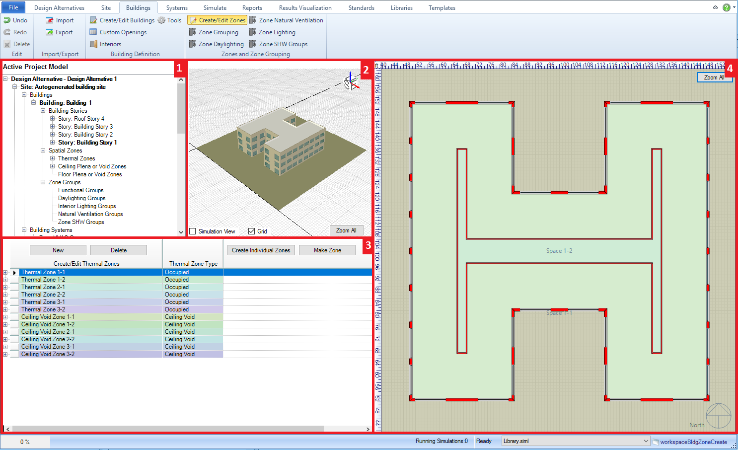
The Workspace is comprised of four areas:
Project/Component Tree (top left) - allows the user to see the connections of different components for the project. Serves more as a tool to review connections versus a tool that enables the simulation workspace
Interactive 3d Model View (middle top) - provides the user a 3d interactive view of the current model to preview site objects that are being and/or have been created.
Create/Edit Thermal Zones (bottom left) - allows the user to create thermal zones that include single or multiple spaces. It is part of the Simergy Hierarchy of Zone Groups and Thermal Zones, which allow the users to configure and group spaces and zones in different ways. Tip: for IFC model imports it is important to review to see that all the BEM spaces are associated with thermal zones or they will not be part of the simulation.
Overall 2d View (right) - different from the Create/Edit Building Stories workspace the drawing controls are not included in the 2d view. The main use in this workspace is to allow the users to visualize which spaces are a part of which thermal zone, as well as assessing if spaces from an imported model (such as IFC) have not been associated with a thermal zone. A space will be shown with a white background if it has not been associated with a thermal zone.
This workspace is where users can define Zone Groups and associate thermal zones with them. It is also the workspace where the BEM input process can start to be streamlined by assigning zone loads and conditions templates and zone templates to the various types of Zone Groups. As users become more familiar with Simergy they will gain insight into how the input process can be streamlined.
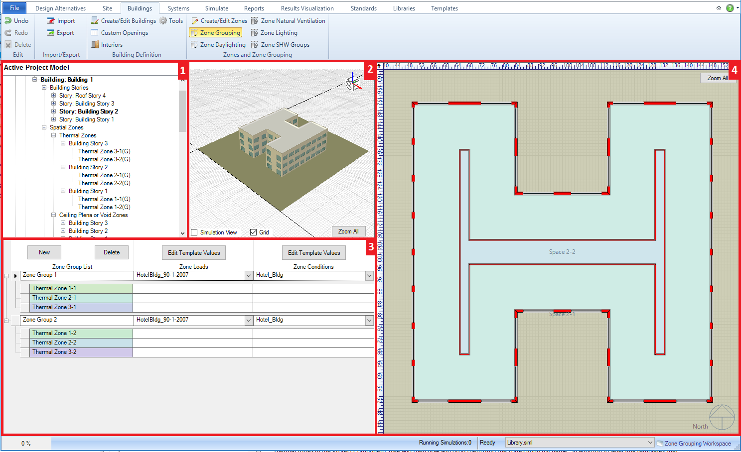
The Workspace is comprised of four areas:
Project/Component Tree (top left) - allows the user to see the connections of different components for the project. Serves more as a tool to review connections versus a tool that enables the simulation workspace. Once you have associated a thermal zone with a Zone Group then the letter (G) will appear next to the thermal zone in the project tree.
Interactive 3d Model View (middle top) - provides the user a 3d interactive view of the current model to preview site objects that are being and/or have been created.
Create/Edit Zone Groups (bottom left) - Enables the user to create different Zone Groups, which can have Zone Loads Templates and Zone Conditions Templates attached. Single thermal zones or thermal zones including multiple spaces can be included in a Zone Group by highlighting the desired thermal zones in the Project Component Tree and then drag and drop them onto the Zone Group list name. In addition to selecting templates that can be quickly associated with Zone Groups, the user can also edit the templates by selecting Edit Template Values. The result is a pop-up dialog that allows the user to edit the desired template and save changes without having to go to the Templates and/or Libraries workspace to make changes. This layout is used by the specific zone group workspaces, such as Daylighting Zone Groups and Service Hot Water Zone Groups. Tip: The input process for a Simergy BEM can be established fairly quickly if the user spends a bit of time thinking about how to leverage the templates that can be applied to Zone Groups.
2d View - Building Canvas (right) - similar to the 2d view in the Create/Edit Zone workspace the user can visualize what thermal zones are associated with different Zone Groups.
______________________________________________________________________________________
© Copyright 2013 Simergy, Sustainable IQ, Inc.