

The sample file ASHRAE -7 VAV (referred to as System 7) available with the Simergy installation at C:\Users\Public\Simergy\Samples\Sample_Projects is a "simulation ready" sample file. The sample file contains all the components and input values required, and is an example of a model containing a HVAC system type that contains multiple water loops and an air loop. It is a sample file that new Simergy users as well as experienced EnergyPlus users will find beneficial to review and study. The following is a breakdown of different components within the sample file that is presented by going through each tab on the Simergy Interface. The Simergy Map also displays all of the Libraries and Templates Categories that are used within the sample file and they are mapped to the different interface tabs.
Only a Baseline Design Design Alternative is included with the file and the location selected is Minneapolis, MN
No site objects are included with this file.
The Building Constructions library entry selected from the drop down list is ASHRAE 90.1 nonRes CZ4-6 (Non-Residential Climate Zone 4-6), which contains the different required construction entries (opaque and fenestration) that are outlined in ASHRAE 90.1-2010. The source for the options available in the drop down list is Templates>Constructions
When you first go to this tab it will appear blank, because the geometry has already been created and the program is ready for you to create a new building forms. When you highlight one or both of the building stories in the Project Tree, you start to see how the basic geometry was created.

The building geometry is nothing special. A two-story square structure that contains core and perimeter zones. As shown in the image above when one of the floors is highlighted the inputs that were selected to create the geometry are displayed. In addition the window configuration for the model was generated by selecting the default of 30% window to wall ratio and there is only one array (plane) of glazing per floor included (up to three per floor can be included), so in this case there is not anything interesting to see on the other tabs unless changes start to be made to the file.
The two story model with core and perimeter zones means there are ten (10) thermal zones currently incorporated into the model (as shown in the image below). This is workspace where thermal zones can be manipulated, added and assigned. It is typically used to view the current thermal zones in a model and to view the thermal zones that have and have not been assigned on an imported model (whether it is IFC or gbxml).

The workspace that allows you to build different types of Zone Groups. In this case there is only one Zone Group and all ten zones have been assigned to it, as is shown when the "+" button is selected next to Zone-Group-1.

Zone Groups can be a time saver to defining inputs for your model. The key question to answer is what zones will have similar Zone Loads and Zone Conditions entries. If the answer is that they are all similar, then you can get away with one Zone Grouping as shown. Otherwise you can create multiple Zone Groups by selecting New.
Clicking Edit Template button displays the library entries that have been selected for each property (row). The properties for Equipment are displayed, but if you could scroll down within the picture you'd see property selections for Lights and People as well. To see a mapping of the property to the value drop down list where the library entries can be viewed and edited, look here.
Clicking Edit Template button displays the library entries that have been selected for each property (row). The properties for Equipment are displayed, but if you could scroll down within the picture you'd see property selections for Lights and People as well. To see a mapping of the property to the value drop down list where the library entries can be viewed and edited, look here.
In this case no Zone Daylighting or Zone Natural Ventilation groups have been set up for the model.
The first destination when the Systems Tab is selected is the Zone HVAC Groups > Create/Edit Workspace. Each Simergy model is required to have at least one Zone HVAC Group, because the demand side for the Air System needs to be defined. The Demand side can either be defined by selecting a Zone HVAC Group template and then dragging that onto the Supply Side or if a Zone HVAC Group, such as one using an Ideal Loads System (compound object containing multiple components), is set up the Air Loop is not required.
In this case of System 7, two Zone HVAC Groups have been set up. One for the core thermal zones and the other for the perimeter. In this case they just happen to have the same Template assigned to them. However, you'll note that "Custom Configuration" is displayed in the Template column. This indicates that changes have been made to the template after it has been assigned to the model. To view the updated template you will need to change the Source Library to Project Model.siml (lower right of workspace), and then you can go to Template>ZoneHVACGroups to select the template and view the properties.
The Zone HVAC Group Templates included within System 7 are:
A common theme in Simergy is that naming conventions for different Template and Library Entries have been set up to provide insight into what is included by just looking at the name.
Note: To edit the inputs for the component shapes and/or to add others to the Zone HVAC Group, you will need to go to the Diagram Workspace.
In either workspace the Heating and Cooling Priority can be set by interacting with the table on the bottom right of the workspace. For each model to simulate successfully each component is required to have a library entry associated with it, so that the needed input values are required. All Templates packaged with the Simergy Installation will contain Library Entries. An example is shown in the image above where the "Zone Temperature Controller" has been selected from the 2d view and if you look to the properties table on the lower left you'll see that the Library Entry selected is a Dual Setpoint Controller.
Another common theme to remember is that to run Validation checks, you'll need to be in the Diagram Workspace. See the "Validate" button at the top center of the 2d diagramming section. By selecting the validation check will be completed that will display 'no errors' or 'list the errors' on the table below the 2d diagramming section (note the Validation tab). In addition, the Validation Dashboard that is located on the Design Alternatives and Simulate workspaces will be updated as well.
Related Topics: Air Loop Interactive Diagram
For System 7 there is one Air Loop that has been set up, which is listed in the table (lower left). The Air Loop was created by first by selecting the VAV_wtrC_wtrH Template from the Air Loop Template drop down list to set up the Supply Side of the Air Loop. The Demand Side of the Air Loop was established by highlighting ZoneHVAC Group 1 & 2 in the project tree and then dragging and dropping them into the Air Loop Table.
Naming Convention for Air Loop Templates - VAV_wtrC_wtrH
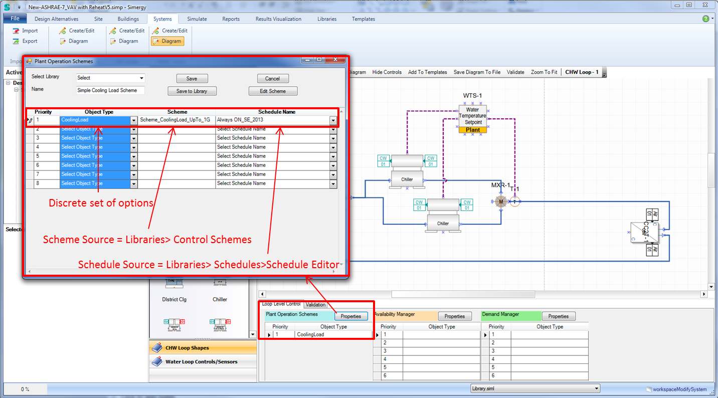
Another requirement to run a simulation within EnergyPlus is that an Availability Manager needs to be associated with each Air Loop. In this case the Object Type = Scheduled has been selected and the "Scheme_AvailMgr_AlwaysOn" library entry that was set up in the Libraries>Scheme List area has been selected.
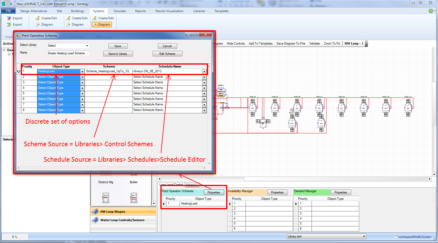
Related Topics: Chilled Water Loop Interactive Diagram
The Chilled Water Loop Selection = Chlr(2)_VC_Elec_VSD(2)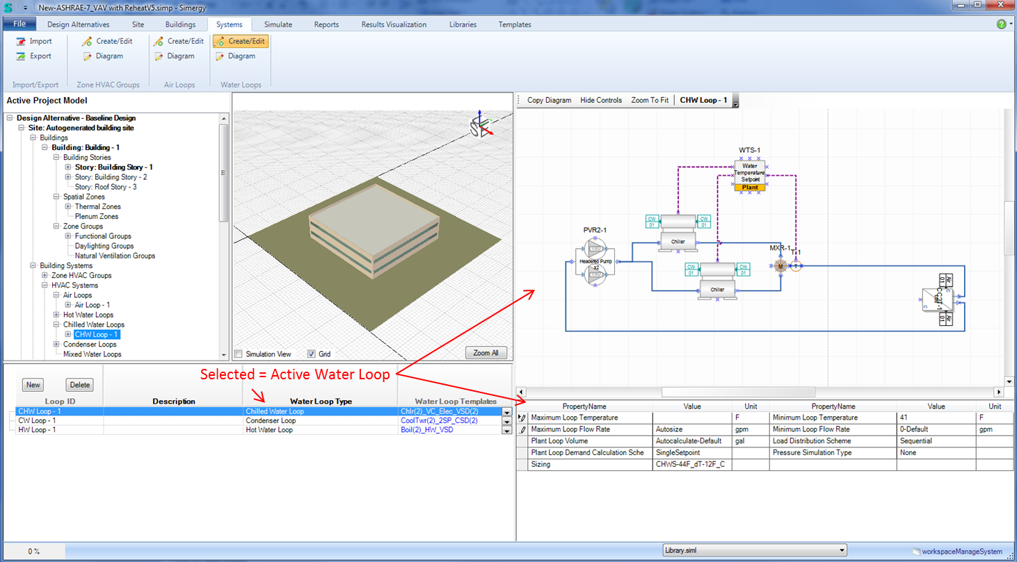
| Property Name | Value Source | Units |
| Maximum Loop Temperature | <input value> | F |
| Maximum Loop Flow Rate | Autosize or <input value> | gpm |
| Plant Loop Volume | Autocalculate or <input value> | gal |
| Plant Loop Demand Calculation Scheme | Single Setpoint or Dual Setpoint Deadband | |
| Sizing | Libraries>Sizing Params Type = HVAC Design Sub Type = Water Loop Sizing |
|
| Minimum Loop Temperature | <input value> | F |
| Minimum Loop Flow Rate | Autosize or <input value> | gpm |
| Load Distribution Scheme | Uniform, Sequential or Optimal | |
| Pressure Simulation Type | None, LoopFlowCorrection, Pump Power Correction |
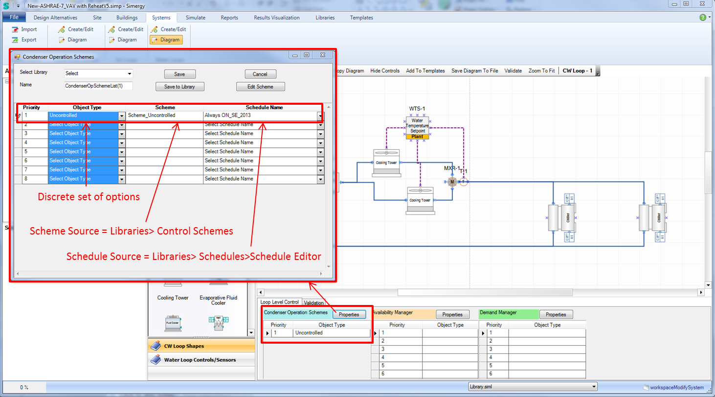
Related Topics: Condenser Water Loop Interactive Diagram
The Condenser Water Loop Selection = CoolTwr(2)_2SP_CSD(2)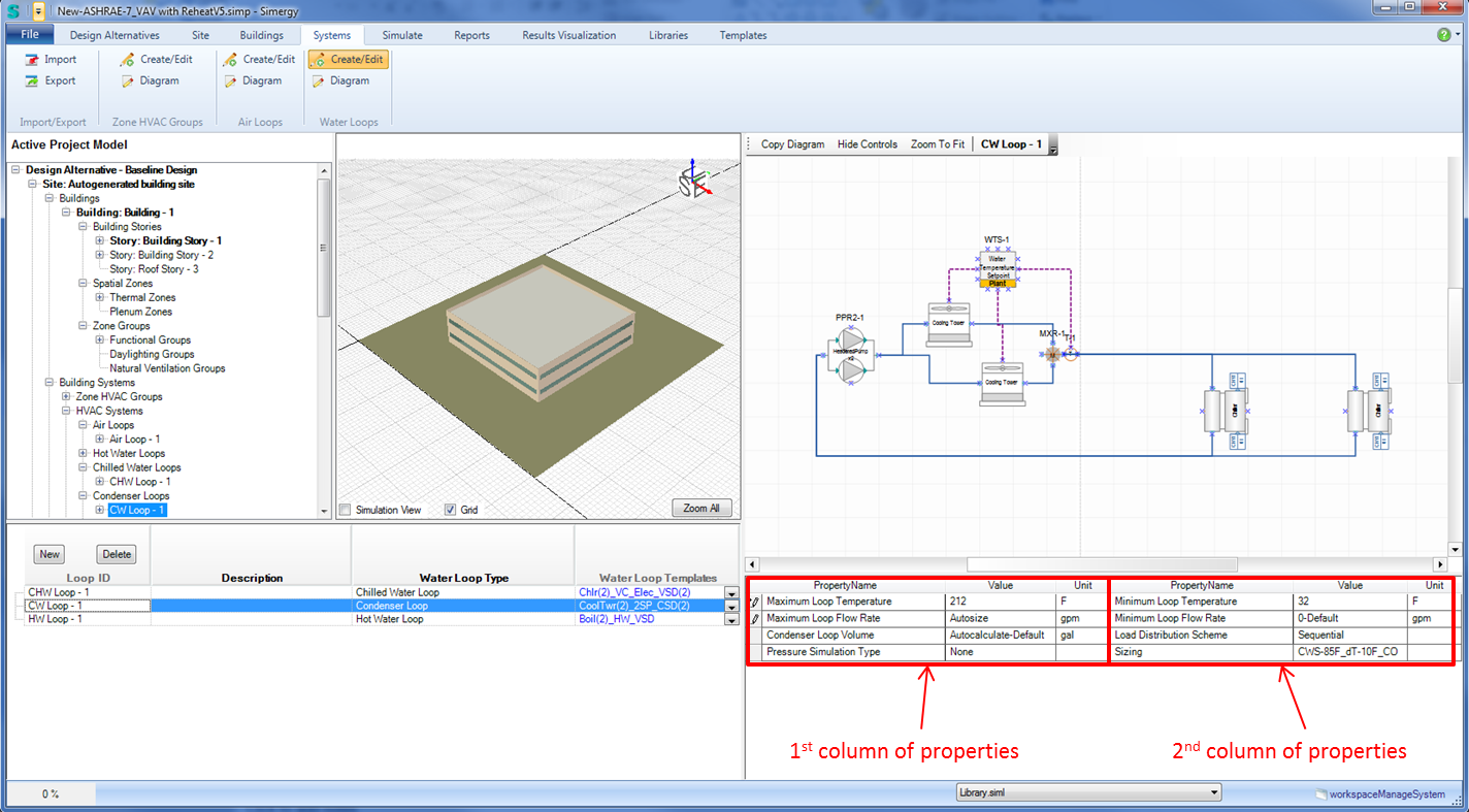
| Property Name | Value Source | Units |
| Maximum Loop Temperature | <input value> | F |
| Maximum Loop Flow Rate | Autosize or <input value> | gpm |
| Condenser Loop Volume | Autocalculate or <input value> | gal |
| Pressure Simulation Type | None, LoopFlowCorrection, Pump Power Correction | |
| Minimum Loop Temperature | <input value> | F |
| Minimum Loop Flow Rate | Autosize or <input value> | gpm |
| Load Distribution Scheme | Uniform, Sequential or Optimal | |
| Sizing | Libraries>Sizing Params Type = HVAC Design Sub Type = Water Loop Sizing |
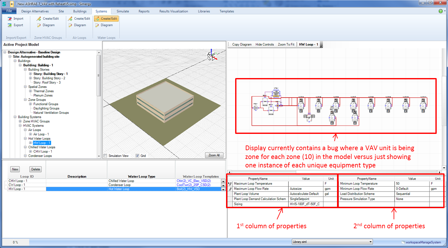
| Property Name | Value Source | Units |
| Maximum Loop Temperature | <input value> | F |
| Maximum Loop Flow Rate | Autosize or <input value> | gpm |
| Plant Loop Volume | Autocalculate or <input value> | gal |
| Plant Loop Demand Calculation Scheme | Single Setpoint or Dual Setpoint Deadband | |
| Sizing | Libraries>Sizing Params Type = HVAC Design Sub Type = Water Loop Sizing |
|
| Minimum Loop Temperature | <input value> | F |
| Minimum Loop Flow Rate | Autosize or <input value> | gpm |
| Load Distribution Scheme | Uniform, Sequential or Optimal | |
| Pressure Simulation Type | None, LoopFlowCorrection, Pump Power Correction |
Simergy ASHRAE System 7 Map
A good habit to get into once you are ready to consider to start to run simulations is to check the different tabs on the "Validation Dashboard" (upper right). It provides an overview of the "integrity of the model", and can assist identifying problem areas that should be addressed before hitting the "Run Simulation" button.
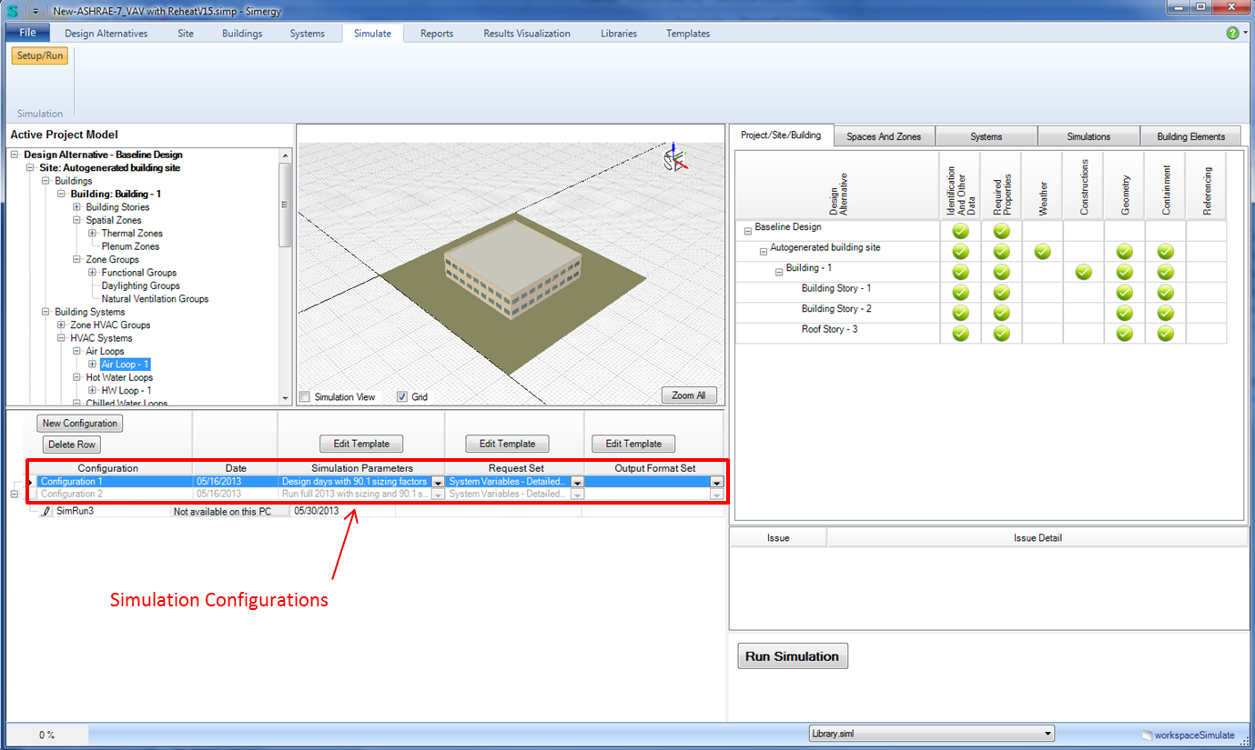
Two simulation configurations have been set up for System 7. Simulation configurations can vary based on selections of Simulation Parameters, Request Sets or Output Format Sets
Note: Selecting an Output Format Set is rarely needed, so a majority of the time this field will remain blank.
In this case the difference between the two configurations is the first is to simulate "Design Days with Sizing" and the second is a "Full Year with Sizing" run.
A Simulation Parameters Template is associated with each configuration.
Actually the templates selected here are Output Request Set Templates.
From the set packaged with Simergy Version 1, System Variables - Detailed Set w/ Zones is associated with each configuration
No Output Format Set Templates are included with System 7.
Simergy ASHRAE System 7 Map
Completed simulation runs are not included with the sample files, but you can run select "Run Simulation" for the two pre-defined configurations to generate them.
Once a simulation has been run "View Results" will appear in the Simulation Configuration table. If you select the button it will take you to the Reports Workspace. As you may recall the Results that are available for a simulation are determined by what Output Variables are included in the Output Request Set selected within the configuration. Typically all of the Request Sets that are included with Simergy contain the Output Variables required for the set of pre-defined Reports. See sections on Reports for additional information
Simergy ASHRAE System 7 Map
Completed simulation runs are not included with the sample files, but you can run select "Run Simulation" for the two pre-defined configurations to generate them.
In this case once the simulations are complete, rather than selecting the "View Results" button, you should just select "Results Visualization" from the top menu to access the workspace. See sections on Results Visualization for additional information.
______________________________________________________________________________________
© Copyright 2013 Simergy, Sustainable IQ, Inc.