Daylighting Controls can be a useful energy efficiency strategy to consider for new construction as well as retrofit. The energy savings are a result of the reduced time and lower levels that interior lights are on or off throughout the year as compared to the lighting schdedule. The Daylight Controls provide the ability to adjust the percentage of interior lighting being used based on the contribution of available daylight in the space. The calculations for Daylighting Controls take a number of external and internal factors into consideration. Potential trade-offs, such as glare, should also be considered when you are trying to optimize the benefit of daylighting controls.
Simergy allows users to analyze daylighting dimming strategies at the overall building level as well as for specific portions and zone groups of the building. The Daylighting Guide walks through the steps required to incorporate Daylighting Controls into your Building Energy Model (BEM), and provides insight into what parameters influence the calculations.
EnergyPlus incorporates two ways to analyze daylighting - 1) Detailed Method; 2) DElight. Simergy incorporates the more precise Detailed Method. There are three main components to the daylighting controls calculations that shape the potential energy savings at each time step:
The diagram tells the story of these three main components and the other parameters that influence them.
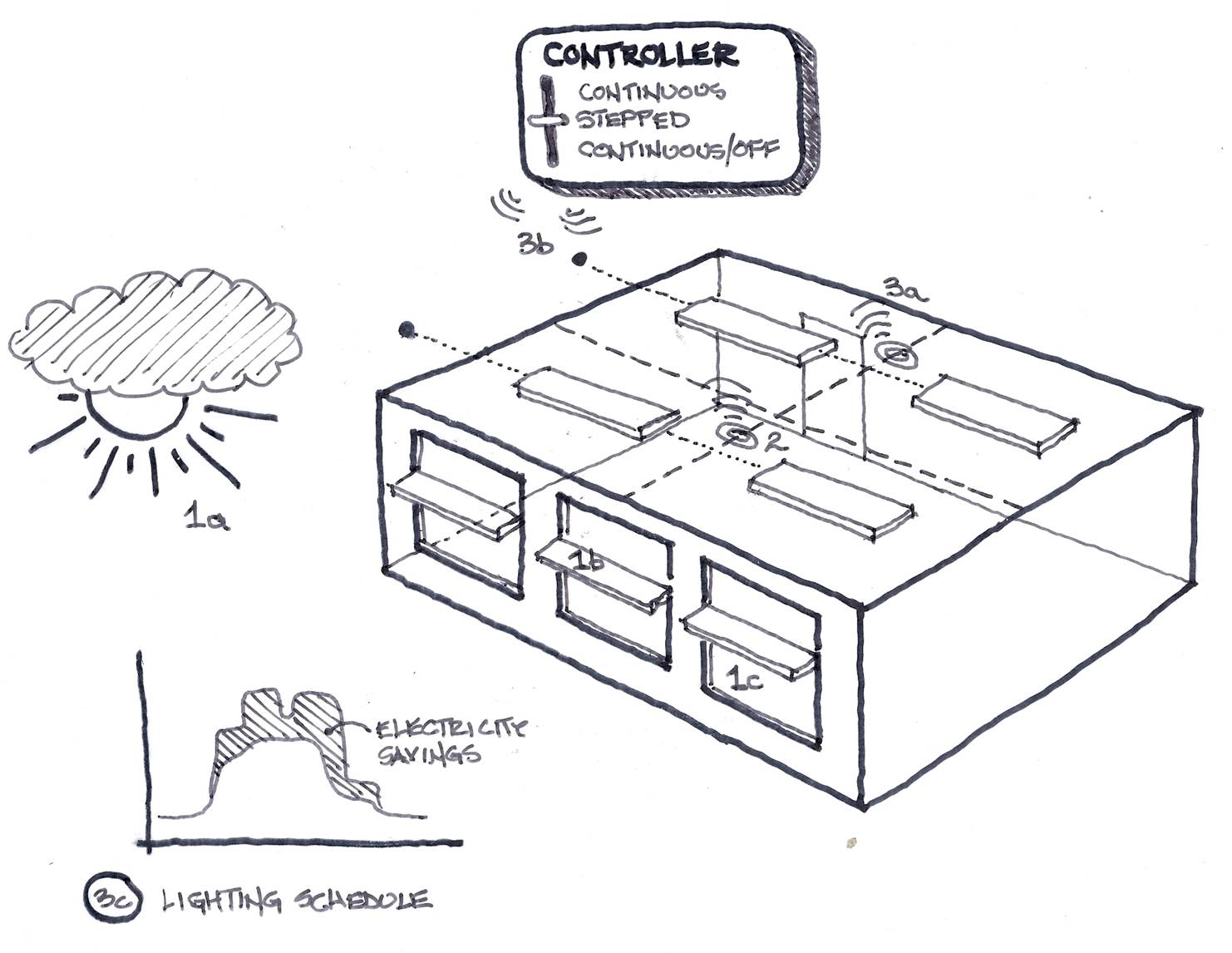
1a - The building climate location, the orientation and the sky condition influence the level of daylight available at a timestep.
1b - Exterior shading in the form of neighboring buildings, trees, and/or exterior shading can further influence the level of daylight available at a timestep.
1c - The glazing composition and type of glazing play a role in the daylight available at the interface of the window
2 - The number of reference points and their location influence the levels of daylight read at each reference point.
3a - The action the controller initiates is influence by the illuminance setpoint at each reference point and the type of control selected
3b - Based on all the parameters above the percentage output for the interior lights at each fixture is determined, which influences the amount of overall energy savings (lighting % scheduled - actual lighting % used) at each timestep.
3c - The annual resulting energy (electricity) savings due to the lower levels of interior lighting
source: EnergyPlus Engineering Reference
The technical description of the daylighting calculation:
A daylighting calculation is performed each time step that the sun is up for each zone that has one or two daylighting reference points specified. The exterior horizontal illuminance from the sun and sky is determined from solar irradiance data from the weather file. The interior illuminance at each reference point is found for each window by interpolating the daylight illuminance factors for the current sun position, then, for sky-related interior illuminance, multiplying by the exterior horizontal illuminance from the appropriate sky types that time step, and, for sun-related interior illuminance, multiplying by the exterior horizontal solar illuminance that time step. By summation, the net illuminance and glare due to all of the windows in a zone are found. If glare control has been specified window shading (by movable shading devices or switchable glazing) is deployed to reduce glare. Finally the illuminance at each reference point for the final window and shade configuration is used by the lighting control system simulation to determine the electric lighting power required to meet the illuminance setpoint at each reference point.
For the daylighting controller to know what it has to work with the daylight entering the space must be calculated. EnergyPlus does this by accounting for the climate location, the orientation of the building and consideration of exterior obstructions, as well as the size, location, glazing configuration and glazing type, and time of day. This determines the daylight availability level at the surface of the glass for each window, but before reaching the reference point the interior obstructions need to be accounted for as well.
Note: Putting the above description in EnergyPlus terms, the Sky Luminance distribution for a time-step is expressed as a linear interpolation of two of the four standard CIE skies (Clear Sky, Clear Turbid Sky, Intermediate Sky, Overcast Sky), which are determined based on the value of sky clearness that has been input. For additional detailed information, see the EnergyPlus Engineering Reference.
Obstructions that influence the amount of daylight that reaches the windows. The obstructions fall into three categories:
Note: All surfaces within the three categories are assumed to be black, unless the Solar Reflectance parameter for the Solar Shade is adjusted.
Obstructions that lie between the window and the reference point. The obstructions are assumed to be opaque, but in the case of walls will typically have a percentage of reflectance associated with them, which can contribute to some daylight contribution reaching the sensor.
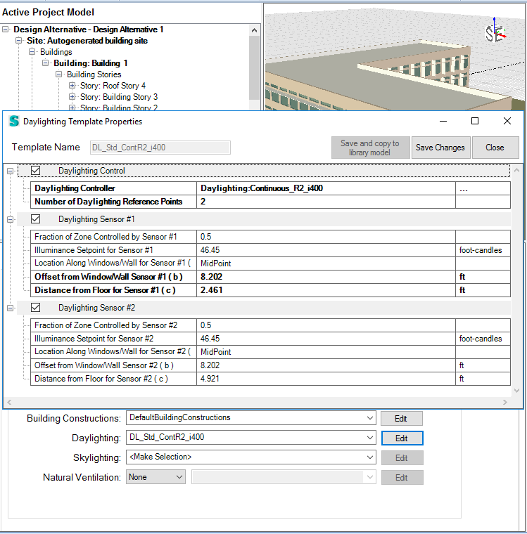
The reference points that appear in a thermal zone when daylighting controls have been activated at the whole building level, and/or associated to a Zone Daylighting Group read the available daylight at each time step. By default two reference points are located in each daylighting thermal zone. By default the first reference point is located near the window and the second near the rear of the space. Each reference point location can be adjusted by changing the input values associated with the Daylighting Template. There you can specify the type of Daylighting Controller, one reference point or two for a space, the sensor type, and the location, as well as the illuminance set point for each sensor and the fraction of the zone controlled by the sensor.
Once the final daylight illuminance value at each reference point has been determined, the electric lighting control is simulated. Each of the two reference points (sensors) independently calculate the lighting power reduction possible at that time step, which informs the daylighting controller based on the type of dimming control (continuous, continuous off or stepped). determines the lighting power reduction for that timestep.
The settings for the Daylighting Controller (Libraries>Controls and Performance Data>Controllers>Daylight) determines the resulting action and therefore energy savings at each time step based on the level of daylight availability and the type of daylighting controls that have been selected. Here you specify one of three Lighting Control Types (continuous, stepped, continuous/off) and the associated inputs with each as well as inputs for glare and availability schedules.
Depending on the Lighting Control Type and the associated settings the Daylighting controller will determine the percentage interior lighting contribution required and then will adjust the lights related to each reference point accordingly.
Note: The baseline/starting point for the daylighting controller is the lighting schedule, which determines the interior lighting levels for each space at each time step. The percentage that the interior lighting levels can be reduced based on the daylight availability determine the energy savings.
Daylighting controls can be incorporated at the overall building level or at the zone group level.
When activated at the overall building level, then all the zones that are daylit and occupied will have reference points included.
Multiple zones can be selected and incorporated into a Zone Daylighting Group, which can then have a Daylighting Template associated with it. Only those zones included in the Zone Daylighting Groups that have been set up will include daylighting controls.
Note: The same zone can be assigned to multiple Zone Group types (Building, Natural Ventilation and Daylighting).
If you are interested in having one zone with daylighting controls or multiple single zones with different inputs for the daylighting controls, you will need to set up a Daylighting Zone Group for each zone that has different inputs for daylighting controls. Once the Zone Daylighting Groups have been set up, then they can have a Daylighting Template associated with it. Only those zones included in the Zone Daylighting Groups that have been set up will include daylighting controls.
Note: The same zone can be assigned to multiple Zone Group types (Building, Natural Ventilation and Daylighting).
The table identifies different types of daylight modeling that are possible within Simergy, and provides links to more detailed explanations within the Input Output Reference and Simergy Help.
Modeling Option |
Description |
Daylight a Thermal Zone |
You can do this to all thermal zones by 'making daylight active', but you can also do it for a single or set of zones by including them in a zone daylighting group. |
| Specify Visible Transmittance for Glazing | The visible transmittance is specified at the Libraries:Materials level. The Materials library entry is then associated with a Mat'l/Glazing Layer to set the depth of the glazing. Then it is associated with a Mat'l/Glaz Layer Set to establish the 'layered assembly' and then it is associated with a Window library entry. The final stage is a Construction Template that assembles the selections for the opaque and fenestration constructions in one place. |
| Use Electrochromic Glazing to control glare | Electrochromic Glazing (Switchable Glazing) contains a "Dark State" and a "Clear State". A Shading Control Controller defines the "Dark State", and is where you can set "Glare Control Is Active" to "Yes". The "Clear State" is defined in the properties of the Window itself, which is where the Shading Control Controller that has been created can be selected as well. |
| Adjust Electrochromic Glazing to meet daylighting illuminance Setpoint | Set up a Shading Control Controller for Heating_Cooling Loads (Sub Type). Set the Shading Control Type Property to "MeetDaylightIlluminanceSetPoint" for the Shading Type = Switchable Glazing. The Illuminance Setpoint is not defined within this library entry, the Illuminance Setpoint looks to what has been defined in Daylighting Template. When you have activated Daylighting and selected the Daylighting Template, then when you define the Window type that contains the Shading Control property the model is ready. |
| Control Electric Lighting Response to Daylight Illuminance Level | You will need to set up or select a Daylighting Controller to be part of a Daylighting Template that specifies the number of sensor reference points, targeted illuminance level at those sensors and other properties. |
| Model daylighting through double facade | The EnergyPlus Daylighting:Controls (Detailed Method) is incorporated into Simergy. This method enables the ability to model daylight through a double facade (exterior window through a space, through an interior window and into a space). It does not calculate daylight passing through more than one interior window. Care should be taken to position the reference points, but no specific inputs are required to enable this capability. |
| Add diffusing (translucent glass) | Diffusing glass can be specified initially at the Glazing Material
level (Solar
Diffusing Property for Material:Glazing), and then that glazing
material will have a thickness provided (Mat'l/Glazing
Layer), be included in a layer set (Mat'l/Glaz
Layer Sets), and then included in a window (Windows).
Note: Solar Diffusing should only be used on the innermost pane of glass in an exterior window; it does not apply to interior windows |
To evaluate if increased daylight due to large glazing areas on the facade and/or based on other parameters (exterior shading, glazing type, etc) you can specify the desired "Maximum Allowable Discomfort Glare Index" value within the Daylighting Controller library entry. This controller is then associated with the Daylighting Template, which is specified when you activate Daylighting Controls at the overall building level or at the Zone Daylighting Group level. If you are interested in reviewing results to see the degree of trade-off for relevant "glare output variables", you will need to select the following output variables and associate them with the Output Request Set prior to running the simulation:
Zone,Average,Glare Index at Ref Point 1 []
Zone,Sum,Time Exceeding Glare Index Setpoint at Ref Point 1
Zone,Average,Glare Index at Ref Point 2 []
Zone,Sum,Time Exceeding Glare Index Setpoint at Ref Point 2
There are three approaches to activating daylighting controls that you can choose from - Whole Building, Whole Building + Zone Daylighting Groups, Daylighting Groups only.
When you want to evaluate the influence of daylighting controls on all the perimeter spaces. You can accomplish this easily, and in one place, by making the daylighting controls active and assigning a daylighting template. You do not have to specify daylighting controls for each space.
Workspace = Buildings > Create/Edit Building > Building Section
Since there is only one Daylighting Method implemented in Simergy, all you need to do is to select Detailed in the first drop down list next to Daylighting on the workspace to activate daylighting controls.
Next select a daylighting template from the second drop down list. A set of Templates is installed with Simergy that can be selected or you can create or edit them in Templates>Daylighting workspace.
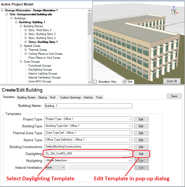
In addition you can view and make changes to the Detailed Daylighting Template by selecting Edit, which will open a pop-up dialog box, which provides the same capability as if you were working in the Templates > Daylighting workspace. Each drop down list in the value column of the table is linked to a Libraries category that is the source for the list. You can either select a library entry from the available set packaged with the Simergy installation or create your own within the Libraries category. The Detailed Daylighting Template topic identifies the drop down list source for each row and provides links to descriptions.
Note: At least one Zone Group is required for a Simergy to pass the validation checks and an energy model to successfully run.
The thermal zones are assigned to either a single Zone Group or multiple Zone Groups. This step is important because it is where the Zone Loads Templates are assigned, which determines the lighting schedule that will be associated with each Zone Group, in addition to People and Equipment. So if you are planning on having different lighting schedules for different sets of zones, you will need to create multiple Zone Groups.
Note: At this stage Daylighting Controls can be analyzed at the overall building level, because they have been assigned to each zone within the model. if the intent is to analyze Daylighting Controls for certain thermal zones, then the user can set up Zone Daylighting Groups.

At this point, if the rest of the relevant inputs for the BEM are complete, the user can setup the simulation configuration(s), choose which output variables to associate with the simulation , run the simulation(s), and then evaluate the results.
When you want to evaluate the influence of daylighting controls on all the perimeter spaces, but you have different types of daylighting controls in different parts of the building.
Note: the same first four steps as the Whole Building Level Process are required to activate daylighting controls for all the perimeter spaces. One of the most important is setting up the Zone Group, because the Zone Loads Template specifies the Lighting Schedule. Only a few additional steps are required to incorporate different daylighting controls for different Zone Daylighting Groups.
Workspace = Buildings > Zone Daylighting
You can set up a Zone Daylighting Group by selecting New. You can use the default name provided or change it. You can select the desired single thermal zone or multiple thermal zones from the Active Project Model tree, and then drag and drop thermal zones onto the desired Zone Daylighting Group.
Note: After thermal zones have been associated with a group type, abbreviations will appear behind the thermal zone name.
After the thermal zone or zones have been assigned to the Zone Daylighting Group. Next select a daylighting template from the second drop down list. A set of Templates is installed with Simergy that can be selected or you can create or edit them in Templates>Daylighting workspace.
Note: Also note that by assigning a different daylighting template it overrides the daylighting template at the whole building level for this set of thermal zones. The remaining perimeter thermal zones will still have the Daylighting Template assigned to them that was designated at the Buildings > Create/Edit Building > Building Section workspace.
Repeat the two steps above for each Zone Daylighting Group that you want to include in your BEM that will have unique Daylighting Control inputs.
Note: Customization can be done at either the Template and Library level or at both. For example, based on the size of the thermal zone you may feel you only need one reference point, versus the two default reference points. Therefore, you would change the Daylighting Template. However, if you wanted to change the lighting control type, you would need to change the library entry for the Daylight Controller, which would then be associated with the Daylighting Template.
At this point, if the rest of the relevant inputs for the BEM are complete, the user can setup the simulation configuration(s), choose which output variables to associate with the simulation , run the simulation(s), and then evaluate the results.
When you are interested in evaluating the impact of daylighting controls on a set of perimeter zones, but not the overall building. In this case you can go straight to setting up Daylighting Zone Groups and you do not need to activate the whole building daylighting controls on the Buildings > Create/Edit Building > Building Section workspace.
Workspace = Buildings > Zone Daylighting
You can set up a Zone Daylighting Group by selecting New. You can use the default name provided or change it. You can select the desired single thermal zone or multiple thermal zones from the Active Project Model tree, and then drag and drop thermal zones onto the desired Zone Daylighting Group.
Note: After thermal zones have been associated with a group type, abbreviations will appear behind the thermal zone name.
After the thermal zone or zones have been assigned to the Zone Daylighting Group. Next select a daylighting template from the second drop down list. A set of Templates is installed with Simergy that can be selected or you can create or edit them in Templates>Daylighting workspace.
Note: Also note that by assigning a different daylighting template it overrides the daylighting template at the whole building level for this set of thermal zones. The remaining perimeter thermal zones will still have the Daylighting Template assigned to them that was designated at the Buildings > Create/Edit Building > Building Section workspace.
Repeat the two steps above for each Zone Daylighting Group that you want to include in your BEM that will have unique Daylighting Control inputs.
Note: Customization can be done at either the Template and Library level or at both. For example, based on the size of the thermal zone you may feel you only need one reference point, versus the two default reference points. Therefore, you would change the Daylighting Template. However, if you wanted to change the lighting control type, you would need to change the library entry for the Daylight Controller, which would then be associated with the Daylighting Template.
At this point, if the rest of the relevant inputs for the BEM are complete, the user can setup the simulation configuration(s), choose which output variables to associate with the simulation , run the simulation(s), and then evaluate the results.
Note: You will need to have one Zone Group included in the BEM for Simergy to successfully simulate.
There are a number of output variables associated with daylighting and lighting that are available within EnergyPlus to be included in Simergy Output Request Sets. The output variables fall into three main categories:
The section for each category identifies the list of output variables and identifies common ones that you might be interested in including in the Output Request Set if you are incorporating daylighting controls. The recommended output variables also include descriptions as well.
Note: You can also set up a Result Screen that you could associate with the a Template Starter file and use it across all your BEMs.
The overall list of daylighting output variables that can be associated with BEMs. The highlighted (bold) output variables are recommended, and include descriptions. Detailed explanations for the other output variables are located in the Daylighting Output section of the EnergyPlus Input Output Reference. The units shown are SI, but the user can change to Imperial Units by selecting File/Options/User Interface Measure Units and selecting Imperial Units.
Zone,Average,Exterior Beam Normal Illuminance [lux]
Zone,Average,Exterior Horizontal Beam Illuminance [lux]
Zone,Average,Exterior Horizontal Illuminance From Sky [lux]
Zone,Average,Luminous Efficacy of Beam Solar Radiation [lum/W]
Zone,Average,Luminous Efficacy of Sky Diffuse Solar Radiation [lum/W]
Zone,Average,Sky Clearness for Daylighting Calculation []
Zone,Average,Sky Brightness for Daylighting Calculation []
Surface,Average,Daylight Luminance of Window As Viewed From Ref Point 1 [cd/m2]
Surface,Average,Daylight Illum at Ref Point 1 from Window [lux]
Zone,Average,Daylight Illum at Ref Point 1 [lux]
Zone,Average,Glare Index at Ref Point 1 []
Zone,Sum,Time Exceeding Glare Index Setpoint at Ref Point 1 [hr]
Zone,Sum,Time Exceeding Daylight Illuminance Setpoint at Ref Point 1 [hr]
Surface,Average,Daylight Luminance of Window As Viewed From Ref Point 2 [cd/m2]
Surface,Average,Daylight Illum at Ref Point 2 from Window [lux]
Zone,Average,Daylight Illum at Ref Point 2 [lux], if applicable
Zone,Average,Glare Index at Ref Point 2 [], if applicable
Zone,Sum,Time Exceeding Glare Index Setpoint at Ref Point 2 [hr]
Zone,Sum,Time Exceeding Daylight Illuminance Setpoint at Ref Point 2 [hr]
Zone,Average,Ltg Power Multiplier from Daylighting []
The area-averaged luminance of an exterior window as viewed from the first reference point in the daylit zone containing the window. In general, higher window luminance values are associated with higher daylight glare values. (Printed only for exterior windows in daylit zones without interior windows.)
The contribution from a particular exterior window to the daylight illuminance at the first reference point in the daylit zone containing the window. (Not printed for exterior windows in daylit zones with interior windows.)
The total daylight illuminance at the first reference point from all of the exterior windows in a daylit zone.
The number of hours when the calculated daylight glare index at the first reference point exceeds the glare index setpoint.
The number of hours when the calculated daylight illuminance at the first reference point exceeds the daylight illuminance setpoint.
The number of hours when the calculated daylight glare index at the second reference point exceeds the glare index setpoint.
The number of hours when the calculated daylight illuminance at the second reference point exceeds the daylight illuminance setpoint.
The amount by which the overhead electric lighting power in a zone is multiplied due to usage of daylighting to dim or switch electric lights. For example, if the multiplier is M and the electric power without dimming is P, then the electric power with dimming is M*P. The multiplier varies from 0.0, which corresponds to maximum dimming (zero electric lighting), to 1.0, which corresponds to no dimming.
Note: If daylighting controls are operating in the zone, all of the Lights objects with a Fraction Replaceable greater than zero will be reduced by a multiplicative factor that accounts for how much the electric lighting is lowered due to daylighting.
Detailed explanations for each are in the Lighting Output section of the EnergyPlus Input Output Reference. The units shown are SI, but the user can change to Imperial Units by selecting File/Options/User Interface Measure Units and selecting Imperial Units.
Lights objects have output variables for individual objects and for zone totals.
Zone,Average,Lights Electric Power [W]
Zone,Sum,Lights Radiant Heat Gain [J]
Zone,Average,Lights Radiant Heat Gain Rate [W]
Zone,Sum,Lights Visible Heat Gain [J]
Zone,Average,Lights Visible Heat Gain Rate [W]
Zone,Sum,Lights Convective Heat Gain [J]
Zone,Average,Lights Convective Heat Gain Rate [W]
Zone,Sum,Lights Return Air Heat Gain [J]
Zone,Average,Lights Return Air Heat Gain Rate [W]
Zone,Sum,Lights Total Heat Gain [J]
Zone,Average,Lights Total Heat Gain Rate [W]
Zone,Sum,Lights Electric Consumption [J]
Zone,Average,Zone Lights Electric Power [W]
Zone,Sum,Zone Lights Radiant Heat Gain [J]
Zone,Average,Zone Lights Radiant Heat Gain Rate [W]
Zone,Sum,Zone Lights Visible Heat Gain [J]
Zone,Average,Zone Lights Visible Heat Gain Rate [W]
Zone,Sum,Zone Lights Convective Heat Gain [J]
Zone,Average,Zone Lights Convective Heat Gain Rate [W]
Zone,Sum,Zone Lights Return Air Heat Gain [J]
Zone,Average,Zone Lights Return Air Heat Gain Rate [W]
Zone,Sum,Zone Lights Total Heat Gain [J]
Zone,Average,Zone Lights Total Heat Gain Rate [W]
Zone,Sum,Zone Lights Electric Consumption [J]
The meters in the table can be selected and included in the Output Request Set in the same fashion as the output variables.
Meter Name |
Scope |
Results |
Electricity:Facility |
Entire Facility | All |
| Electricity:Building | All Zones | All |
| Electricity:Zone:<Zone Name> | Specific Zone | All |
| Interior Lights: Electricity | All Zones | Lights Use |
| Interior Lights: Electricity:Zone:<Zone Name> | Specific Zone | Lights Use |
| <End-Use Subcategory>:Interior Lights: Electricity | Specific Subcategory | Lights Use |
Once you get familiar with the naming conventions, you will start to be able to understand key input values for library entries and templates by just looking at the name.
The intent is to convey key performance characteristics about the library entry within the name, so that the user has some insight into what these key input values are when they are selecting the library entry, so they don't have to go back to that workspace to look at the property input values.
Example Name = Daylighting:Continuous_R2_i500
The intent is to convey key performance characteristics about the template within the name, so that the user has some insight into what these key input values are when they are selecting the template, so they don't have to go back to that workspace to look at the property input values.
Example Name = DL_Std_ContR2_i500
______________________________________________________________________________________
© Copyright 2013 Simergy, Sustainable IQ, Inc.