Input Output Reference
The Encyclopedic Reference to EnergyPlus Input and Output
Date: September 28, 2012
What’s different about EnergyPlus Input and Output?
Input – Output Descriptions (Document)
Group -- Simulation Parameters
SurfaceConvectionAlgorithm:Inside
SurfaceConvectionAlgorithm:Outside
HeatBalanceSettings:ConductionFiniteDifference
ZoneCapacitanceMultiplier:ResearchSpecial
Group -- Location – Climate – Weather File Access
SizingPeriod:WeatherFileConditionType
RunPeriodControl:DaylightSavingTime
WeatherProperty:SkyTemperature
Site:GroundTemperature:BuildingSurface
Site:GroundTemperature:Shallow
Site:GroundTemperature:FCfactorMethod
Site:GroundReflectance:SnowModifier
Outputs for local temperature/wind speed calculations
Group – Surface Construction Elements
Specifying the Building Envelope
Material and Material Properties
MaterialProperty:MoisturePenetrationDepth:Settings
Moisture Penetration Depth (EMPD) Outputs
MaterialProperty:VariableThermalConductivity
Conduction Finite Difference (CondFD) Outputs
MaterialProperty:HeatAndMoistureTransfer:Settings
MaterialProperty:HeatAndMoistureTransfer:SorptionIsotherm
MaterialProperty:HeatAndMoistureTransfer:Suction
MaterialProperty:HeatAndMoistureTransfer:Redistribution
MaterialProperty:HeatAndMoistureTransfer:Diffusion
MaterialProperty:HeatAndMoistureTransfer:ThermalConductivity
Heat and Moisture (HAMT) Outputs
Materials for Glass Windows and Doors
WindowMaterial:Glazing:RefractionExtinctionMethod
Glass Optical Properties Conversion
WindowMaterial:GlazingGroup:Thermochromic
WindowMaterial:GlazingGroup:Thermochromic Outputs
WindowMaterial:SimpleGlazingSystem
MaterialProperty:GlazingSpectralData
Site:GroundTemperature:FCfactorMethod
Construction:CfactorUndergroundWall
Construction:FfactorGroundFloor
Construction:UseHBAlgorithmCondFDDetailed
Group – Thermal Zone Description/Geometry
Surface Output Variables/Reports
Surface Output Variables (all heat transfer surfaces)
Surface Output Variables (exterior heat transfer surfaces)
Opaque Surface Output Variables
Shading:Site, Shading:Building
Shading:Site:Detailed, Shading:Building:Detailed
WindowProperty:FrameAndDivider
Importing Windows from WINDOW 5
Group – Advanced Surface Concepts
SurfaceControl:MoveableInsulation
SurfaceProperty:OtherSideCoefficients
SurfaceProperty:OtherSideConditionsModel
SurfaceConvectionAlgorithm:Inside:AdaptiveModelSelections
SurfaceConvectionAlgorithm:Outside:AdaptiveModelSelections
SurfaceConvectionAlgorithm:Inside:UserCurve
SurfaceConvectionAlgorithm:Outside:UserCurve
SurfaceProperty:ConvectionCoefficients
SurfaceProperty:ConvectionCoefficients:MultipleSurface
Convection Coefficient Application Hierarchy
Convection Coefficients Outputs
SurfaceProperties:VaporCoefficients
SurfaceProperty:ExteriorNaturalVentedCavity
SurfaceProperty:ExteriorNaturalVentedCavity Outputs
ZoneProperty:UserViewFactors:bySurfaceName
Group – Detailed Ground Heat Transfer
RoomAir:TemperaturePattern:UserDefined
RoomAir:TemperaturePattern:ConstantGradient
RoomAir:TemperaturePattern:TwoGradient
RoomAir:TemperaturePattern:NondimensionalHeight
RoomAir:TemperaturePattern:SurfaceMapping
RoomAirSettings:OneNodeDisplacementVentilation
RoomAirSettings:ThreeNodeDisplacementVentilation
RoomAirSettings:CrossVentilation
RoomAirSettings:UnderFloorAirDistributionInterior
RoomAirSettings:UnderFloorAirDistributionExterior
RoomAir:TemperaturePattern:TwoGradient Outputs
Mundt Model / OneNodeDisplacementVentilation Outputs
ThreeNodeDisplacementVentilation Outputs
CrossVentilation Model Outputs
UnderFloorAirDistributionInterior/Exterior Model Outputs
Group – Internal Gains (People, Lights, Other internal zone equipment)
Simplified ASHRAE 55-2004 Graph Related Outputs
Electric, Gas, Other, HotWater, Steam Equipment Outputs
ZoneContaminantSourceAndSink:CarbonDioxide
ZoneContaminantSourceAndSink:CarbonDioxide Outputs
ZoneBaseboard:OutdoorTemperatureControlled
ZoneBaseboard:OutdoorTemperatureControlled Output
Guidelines for Daylighting Modeling (Detailed Method)
Daylighting:DELight:ReferencePoint
Daylighting:DELight:ComplexFenestration
OutputControl:IlluminanceMap:Style
Tubular Daylighting Device Output
Shelf Daylighting Device Output
Group – Exterior Energy Use Equipment
Exterior Fuel Equipment, Exterior Water Equipment Outputs
ZoneInfiltration:DesignFlowRate
ZoneInfiltration:EffectiveLeakageArea
ZoneInfiltration:FlowCoefficient
ZoneVentilation:DesignFlowRate
ZoneVentilation:WindandStackOpenArea
ZoneAirBalance:OutdoorAir Outputs
Refrigeration Door Mixing Outputs
ZoneThermalChimney (Thermal Chimney)
Input for Design Calculations and Component Autosizing
DesignSpecification:OutdoorAir
HVAC: Primary and Secondary Systems
Group – Node-Branch Management
PipingSystem:Underground Class Objects
PipingSystem:Underground:Domain
PipingSystem:Underground:PipeCircuit
PipingSystem:Underground:PipeSegment
PipingSystem:Underground Outputs
Group – Plant-Condenser Control
Operation Schemes (Plant and Condenser)
PlantEquipmentOperationSchemes
CondenserEquipmentOperationSchemes
PlantEquipmentOperation:Uncontrolled
PlantEquipmentOperation:CoolingLoad
PlantEquipmentOperation:HeatingLoad
PlantEquipmentOperation:OutdoorDryBulb
PlantEquipmentOperation:OutdoorWetBulb
PlantEquipmentOperation:OutdoorRelativeHumidity
PlantEquipmentOperation:OutdoorDewpoint
PlantEquipmentOperation:OutdoorDryBulbDifference
PlantEquipmentOperation:OutdoorWetBulbDifference
PlantEquipmentOperation:OutdoorDewpointDifference
PlantEquipmentOperation:ComponentSetpoint
Indirect Absorption Chiller Outputs
Chiller:Electric:ReformulatedEIR
Electric Reformulated EIR Chiller Outputs
Combustion Turbine Chiller Outputs
ChillerHeater:Absorption:DirectFired
Direct Fired Absorption Chiller Outputs
ChillerHeater:Absorption:DoubleEffect
Exhaust Fired Absorption Chiller Outputs
HeatPump:WaterToWater:EquationFit:Cooling
HeatPump:WaterToWater:EquationFit:Heating
HeatPump:WaterToWater:ParameterEstimation:Cooling
HeatPump:WaterToWater:ParameterEstimation:Heating
Water to Water Heat Pump Parameter Estimation Outputs
Water to Water Heat Pump Equation Fit Outputs
Thermal Storage:Ice:Simple Outputs
ThermalStorage:ChilledWater:Mixed
ThermalStorage:ChilledWater:Mixed Outputs
ThermalStorage:ChilledWater:Stratified
ThermalStorage:ChilledWater:Stratified Outputs
Water Heater:Stratified Outputs
CoolingTower:SingleSpeed Outputs
Cooling Tower:Two Speed Outputs
Cooling Tower:Variable Speed Outputs
CoolingTowerPerformance:CoolTools
CoolingTowerPerformance:CoolTools Outputs
CoolingTowerPerformance:YorkCalc
CoolingTowerPerformance:YorkCalc Outputs
EvaporativeFluidCooler:SingleSpeed
EvaporativeFluidCooler:SingleSpeed Outputs
EvaporativeFluidCooler:TwoSpeed
EvaporativeFluidCooler:TwoSpeed Outputs
FluidCooler:SingleSpeed Outputs
Surface Heat Exchanger Outputs
HeatExchanger:Hydronic Outputs
HeatExchanger:WatersideEconomizer
HeatExchanger:WatersideEconomizer Outputs
Group – Plant-Condenser Flow Control
Connector:Splitter, Connector:Mixer
Outdoor Air Ventilation Report Variables
System Component Loads Outputs
System Component Energy Use Outputs
AvailabilityManagerAssignmentList
AirLoopHVAC:OutdoorAirSystem:EquipmentList
What the Airflow Network Model Can and Cannot Do
AirflowNetwork:SimulationControl
AirflowNetwork:Multizone:Surface
AirflowNetwork:MultiZone:ReferenceCrackConditions
AirflowNetwork:MultiZone:Surface:Crack
AirflowNetwork:MultiZone:Surface:EffectiveLeakageArea
AirflowNetwork:MultiZone:Component:DetailedOpening
AirflowNetwork:MultiZone:Component:HorizontalOpening
AirflowNetwork:MultiZone:Component:SimpleOpening
AirflowNetwork:MultiZone:Component:ZoneExhaustFan
AirflowNetwork:MultiZone:ExternalNode
AirflowNetwork:MultiZone:WindPressureCoefficientArray
AirflowNetwork:MultiZone:WindPressureCoefficientValues
AirflowNetwork:Distribution:Node
AirflowNetwork:Distribution:Component:Leak
AirflowNetwork:Distribution:Component:LeakageRatio
AirflowNetwork:Distribution:Component:Duct
AirflowNetwork:Distribution:Component:ConstantVolumeFan
AirflowNetwork:Distribution:Component:Coil
AirflowNetwork:Distribution:Component:HeatExchanger
AirflowNetwork:Distribution:Component:TerminalUnit
AirflowNetwork:Distribution:Component:ConstantPressureDrop
AirflowNetwork:Distribution:Linkage
Group – Air Distribution Equipment
AirTerminal:SingleDuct:Uncontrolled
AirTerminal:SingleDuct:Uncontrolled Outputs
AirTerminal:SingleDuct:ConstantVolume:Reheat
AirTerminal:SingleDuct:ConstantVolume:Reheat Outputs
AirTerminal:SingleDuct:VAV:Reheat
AirTerminal:SingleDuct:VAV:Reheat Outputs
AirTerminal:SingleDuct:VAV:Reheat:VariableSpeedFan
AirTerminal:SingleDuct:VAV:Reheat:VariableSpeedFan Outputs
AirTerminal:SingleDuct:VAV:HeatAndCool:Reheat
AirTerminal:SingleDuct:VAV:HeatAndCool:Reheat Outputs
AirTerminal:SingleDuct:VAV:NoReheat
AirTerminal:SingleDuct:VAV:NoReheat Outputs
AirTerminal:SingleDuct:VAV:HeatAndCool:NoReheat
AirTerminal:SingleDuct:VAV:HeatAndCool:NoReheat Outputs
AirTerminal:SingleDuct:SeriesPIU:Reheat
AirTerminal:SingleDuct:SeriesPIU:Reheat Outputs
AirTerminal:SingleDuct:ParallelPIU:Reheat
AirTerminal:SingleDuct:ParallelPIU:Reheat Outputs
AirTerminal:SingleDuct:ConstantVolume:FourPipeInduction
AirTerminal:SingleDuct:ConstantVolume:FourPipeInduction Outputs
AirTerminal:SingleDuct:ConstantVolume:CooledBeam
AirTerminal:SingleDuct:ConstantVolume:CooledBeam Outputs
AirTerminal:DualDuct:ConstantVolume
AirTerminal:DualDuct:ConstantVolume Outputs
AirTerminal:DualDuct:VAV Outputs
AirTerminal:DualDuct:VAV:OutdoorAir
AirTerminal:DualDuct:VAV:OutdoorAir Outputs
ZoneHVAC:IdealLoadsAirSystem Outputs
ZoneHVAC:OutdoorAirUnit Outputs
ZoneHVAC:OutdoorAirUnit:EquipmentList
ZoneHVAC:WindowAirConditioner Outputs
ZoneHVAC:PackagedTerminalAirConditioner
ZoneHVAC:PackagedTerminalAirConditioner Outputs
ZoneHVAC:PackagedTerminalHeatPump
ZoneHVAC:PackagedTerminalHeatPump Outputs
ZoneHVAC:RefrigerationChillerSet
ZoneHVAC:WaterToAirHeatPump Outputs
ZoneHVAC:Dehumidifier:DX Outputs
ZoneHVAC:EnergyRecoveryVentilator
ZoneHVAC:EnergyRecoveryVentilator Outputs
ZoneHVAC:TerminalUnit:VariableRefrigerantFlow
ZoneHVAC:TerminalUnit:VariableRefrigerantFlow Outputs
AirLoopHVAC:Unitary:Furnace:HeatCool
AirLoopHVAC:Unitary:Furnace:HeatCool Outputs
AirLoopHVAC:UnitaryHeatCool Outputs
AirLoopHVAC:UnitaryHeatPump:AirToAir
AirLoopHVAC:UnitaryHeatPump:AirToAir Outputs
AirLoopHVAC:UnitaryHeatPump:AirToAir:MultiSpeed
AirLoopHVAC:UnitaryHeatPump:AirToAir:MultiSpeed Outputs
AirLoopHVAC:Unitary:Furnace:HeatOnly
AirLoopHVAC:Unitary:Furnace:HeatOnly Outputs
AirLoopHVAC:UnitaryHeatOnly Outputs
AirLoopHVAC:UnitaryHeatPump:WaterToAir
AirLoopHVAC:UnitaryHeatPump:WaterToAir Outputs
AirLoopHVAC:UnitaryHeatCool:VAVChangeoverBypass
AirLoopHVAC:UnitaryHeatCool:VAVChangeoverBypass Outputs
AirLoopHVAC:UnitaryCoolOnly Outputs
Group – Variable Refrigerant Flow Equipment
AirConditioner:VariableRefrigerantFlow
AirConditioner:VariableRefrigerantFlow Outputs
Group – Radiative / Convective Units
ZoneHVAC:Baseboard:RadiantConvective:Water
ZoneHVAC:Baseboard:RadiantConvective:Water Outputs
ZoneHVAC:Baseboard:RadiantConvective:Steam
ZoneHVAC:Baseboard:RadiantConvective:Steam Outputs
ZoneHVAC:Baseboard:RadiantConvective:Electric
ZoneHVAC:Baseboard:RadiantConvective:Electric Outputs
ZoneHVAC:Baseboard:Convective:Water
ZoneHVAC:Baseboard:Convective:Water Outputs
ZoneHVAC:Baseboard:Convective:Electric
ZoneHVAC:Baseboard:Convective:Electric Outputs
ZoneHVAC:LowTemperatureRadiant:VariableFlow
ZoneHVAC:LowTemperatureRadiant:VariableFlow Outputs
ZoneHVAC:LowTemperatureRadiant:ConstantFlow
ZoneHVAC:LowTemperatureRadiant:ConstantFlow Outputs
ZoneHVAC:LowTemperatureRadiant:Electric
ZoneHVAC:LowTemperatureRadiant:Electric Outputs
ZoneHVAC:LowTemperatureRadiant:SurfaceGroup
ZoneHVAC:HighTemperatureRadiant
ZoneHVAC:HighTemperatureRadiant Outputs
ZoneHVAC:VentilatedSlab Outputs
ZoneHVAC:VentilatedSlab:SlabGroup
Refrigeration Compressor Rack Outputs
Refrigeration:CaseAndWalkInList
Refrigeration:Compressor Outputs
Refrigeration:Subcooler Outputs
Refrigeration:Condenser:AirCooled
Refrigeration:Condenser:AirCooled Outputs
Refrigeration:Condenser:EvaporativeCooled
Refrigeration:Condenser:EvaporativeCooled Outputs
Refrigeration:Condenser:WaterCooled
Refrigeration:Condenser:WaterCooled Outputs
Refrigeration:Condenser:Cascade
Refrigeration:Condenser:Cascade Outputs
Refrigeration:TransferLoadList
Refrigeration:SecondarySystem Outputs
Additional Refrigeration Outputs Available for Each Zone
Additional Refrigeration Outputs for Each Zone
Refrigeration:AirChiller Outputs
Group – Zone Controls – Thermostats and Humidistats
ZoneControl:Thermostat Outputs
ThermostatSetpoint:SingleHeating
ThermostatSetpoint:SingleCooling
ThermostatSetpoint:SingleHeatingOrCooling
ThermostatSetpoint:DualSetpoint
ZoneControl:Thermostat:OperativeTemperature
Zone Control Themostatic Operative Temperature Outputs
ZoneControl:Thermostat:TemperatureAndHumidity
ZoneControl:Humidistat Outputs
ZoneControl:Thermostat:ThermalComfort
ZoneControl:Thermostat:ThermalComfort Outputs
ThermostatSetpoint:ThermalComfort:Fanger:SingleHeating
ThermostatSetpoint:ThermalComfort:Fanger:SingleCooling
ThermostatSetpoint:ThermalComfort:Fanger:SingleHeatingOrCooling
ThermostatSetpoint:ThermalComfort:Fanger:DualSetpoint
ZoneControl:ContaminantController
ZoneControl:ContaminantController Outputs
AirLoopHVAC:SupplyPath, AirLoopHVAC:ReturnPath
SolarCollector:FlatPlate:Water
SolarCollector:FlatPlate:Water Output
SolarCollectorPerformance:FlatPlate
SolarCollectorPerformance:FlatPlate Output
SolarCollector:FlatPlate:PhotovoltaicThermal
SolarCollector:FlatPlate:PhotovoltaicThermal Outputs
SolarCollectorPerformance:PhotovoltaicThermal:Simple
Solar Collector Heating System Plant Connections
SolarCollector:UnglazedTranspired
SolarCollector:UnglazedTranspired Outputs
SolarCollector:UnglazedTranspired:MultiSystem
Pump:VariableSpeed:Condensate Outputs
HeaderedPumps:ConstantSpeed Outputs
HeaderedPumps:VariableSpeed Outputs
Group – Heating and Cooling Coils
Coil:Heating:Desuperheater Outputs
Coil:DX:CoolingEmpirical:VariableRefrigerantFlow
Coil:Cooling:DX:VariableRefrigerantFlow Outputs
Coil:DX:HeatingEmpirical:VariableRefrigerantFlow
Coil:Heating:DX:VariableRefrigerantFlow Outputs
Coil:Cooling:Water:DetailedGeometry
Coil:Cooling:Water:DetailedGeometry Outputs
Coil:Cooling:DX:TwoStageWithHumidityControlMode
Coil:Cooling:DX:MultiSpeed Outputs
Coil:Heating:DX:MultiSpeed Outputs
Coil:WaterHeating:Desuperheater
Coil:WaterHeating:Desuperheater Outputs
CoilSystem:Cooling:DX:HeatExchangerAssisted
CoilSystem:Cooling:DX:HeatExchangerAssisted Outputs
CoilSystem:Cooling:Water:HeatExchangerAssisted
CoilSystem:Cooling:Water:HeatExchangerAssisted Outputs
Coil:WaterHeating:AirToWaterHeatPump
Coil:WaterHeating:AirToWaterHeatPump Outputs
Coil:Cooling:WaterToAirHeatPump:ParameterEstimation
Coil:Cooling:WaterToAirHeatPump:EquationFit
Water to Air Heat Pump Cooling Coil (Parameter Estimation and Equation Fit) Outputs
Coil:Heating:WaterToAirHeatPump:ParameterEstimation
Coil:Heating:WaterToAirHeatPump:EquationFit
Water to Air Heat Pump Heating Coil (parameter Estimation and Equation Fit) Outputs
FanPerformance:NightVentilation
Humidfier:Steam:Electric Outputs
Group – Desiccant Dehumidifiers
Dehumidifier:Desiccant:NoFans Outputs
Desiccant Dehumidifier Outputs
Group – Energy Management System (EMS)
EnergyManagementSystem:Actuator
EnergyManagementSystem:ProgramCallingManager
EnergyManagementSystem:Program
EnergyManagementSystem:Subroutine
EnergyManagementSystem:GlobalVariable
EnergyManagementSystem:OutputVariable
EnergyManagementSystem:TrendVariable
EnergyManagementSystem:InternalVariable
Group – System Availability Managers
AvailabilityManager:ScheduledOn
AvailabilityManager:ScheduledOn Outputs
AvailabilityManager:ScheduledOff
AvailabilityManager:ScheduledOff Outputs
AvailabilityManager:NightCycle Outputs
AvailabilityManager:DifferentialThermostat
AvailabilityManager:DifferentialThermostat Outputs
AvailabilityManager:HighTemperatureTurnOff
AvailabilityManager:HighTemperatureTurnOff Outputs
AvailabilityManager:HighTemperatureTurnOn
AvailabilityManager:HighTemperatureTurnOn Outputs
AvailabilityManager:LowTemperatureTurnOff
AvailabilityManager:LowTemperatureTurnOff Outputs
AvailabilityManager:LowTemperatureTurnOn
AvailabilityManager:LowTemperatureTurnOn Outputs
System Availability Manager:Night Ventilation
AvailabilityManager:NightVentilation Outputs
AvailabilityManager:HybridVentilation
AvailabilityManager:HybridVentilation Outputs
SetpointManager:Scheduled:DualSetpoint
SetpointManager:OutdoorAirReset
SetpointManager:SingleZone:Reheat
SetpointManager:SingleZone:Heating
SetpointManager:SingleZone:Cooling
SetpointManager:SingleZone:Humidity:Minimum
SetpointManager:SingleZone:Humidity:Maximum
SetpointManager:OutdoorAirPretreat
SetpointManager:ReturnAirBypassFlow
SetpointManager:WarmestTemperatureFlow
SetpointManager:MultiZone:Cooling:Average
SetpointManager:MultiZone:Heating:Average
SetpointManager:MultiZone:MinimumHumidity:Average
SetpointManager:MultiZone:MaximumHumidity:Average
SetpointManager:MultiZone:Humidity:Minimum
SetpointManager:MultiZone:Humidity:Maximum
SetpointManager:FollowOutdoorAirTemperature
SetpointManager:FollowSystemNodeTemperature
SetpointManager:FollowGroundTemperature
Controls (Air Loop and Zone Equipment)
Controller:MechanicalVentilation
ZoneHVAC:EnergyRecoveryVentilator:Controller
EvaporativeCooler:Direct:CelDekPad
EvaporativeCooler:Direct:CelDekPad Outputs
EvaporativeCooler:Direct:ResearchSpecial
EvaporativeCooler:Direct:ResearchSpecial Outputs
EvaporativeCooler:Indirect:CelDekPad
EvaporativeCooler:Indirect:CelDekPad Outputs
EvaporativeCooler:Indirect:WetCoil
EvaporativeCooler:Indirect:WetCoil Outputs
EvaporativeCooler:Indirect:ResearchSpecial
EvaporativeCooler:Indirect:ResearchSpecial Outputs
HeatExchanger:AirToAir:FlatPlate
HeatExchanger:AirToAir:FlatPlate Outputs
HeatExchanger:AirToAir:SensibleAndLatent
HeatExchanger:AirToAir:SensibleAndLatent Outputs
HeatExchanger:Desiccant:BalancedFlow
HeatExchanger:Desiccant:BalancedFlow Outputs
HeatExchanger:Desiccant:BalancedFlow:PerformanceDataType1
HeatExchanger:Desiccant:BalancedFlow:PerformanceDataType1 Outputs
Group – Demand Limiting Controls
DemandManagerAssignmentList Outputs
DemandManager:ExteriorLights Outputs
DemandManager:ElectricEquipment
DemandManager:ElectricEquipment Outputs
DemandManager:Thermostats Outputs
Group -- Electric Load Center-Generator Specifications
ElectricLoadCenter:Transformer
ElectricLoadCenter:Transformer Outputs
ElectricLoadCenter:Distribution
ElectricLoadCenter:Distribution Outputs
ElectricLoadCenter:Generators Outputs
ElectricLoadCenter:Inverter:Simple
ElectricLoadCenter:Inverter:FunctionOfPower
ElectricLoadCenter:Inverter:LookUpTable
ElectricLoadCenter:Storage:Simple
ElectricLoadCenter:Storage:Simple Outputs
ElectricLoadCenter:Storage: Battery
ElectricLoadCenter: Storage:Battery Outputs
Generator:InternalCombustionEngine
Generator:InternalCombustionEngine Outputs
Generator:CombustionTurbine Outputs
Generator:MicroTurbine Outputs
Generator:MicroCHP:NonNormalizedParameters
Generator:FuelCell:PowerModule
Generator:FuelCell:StackCooler
Generator:FuelCell:WaterSupply
Generator:FuelCell:AuxiliaryHeater
Generator:FuelCell:ElectricalStorage
Generator:Photovoltaic Outputs
PhotovoltaicPerformance:Simple
PhotovoltaicPerformance:EquivalentOne-Diode
PhotovoltaicPerformance:Sandia
Generator:WindTurbine Outputs:
WaterUse:RainCollector Outputs
FluidProperties:GlycolConcentration
HVACTemplate:Zone:IdealLoadsAirSystem
HVACTemplate:Zone:VAV:FanPowered
HVACTemplate:Zone:WaterToAirHeatPump
HVACTemplate:System:UnitaryHeatPump:AirToAir
HVACTemplate:System:PackagedVAV
HVACTemplate:System:DedicatedOutdoorAir
HVACTemplate:Plant:ChilledWaterLoop
HVACTemplate:Plant:HotWaterLoop
HVACTemplate:Plant:MixedWaterLoop
Conceptual Framework – Variables and Hierarchy
Economic Results Summary Report
Economics Cost Estimate Reporting
LifeCycleCost:NonrecurringCost
LifeCycleCost:UsePriceEscalation
OutputControl:SurfaceColorScheme
OutputControl:ReportingTolerances
Output:Meter and Output:Meter:MeterFileOnly
Output:Meter:Cumulative and Output:Meter:Cumulative:MeterFileOnly
Output:EnvironmentalImpactFactors
Environmental Pollution Impact Outputs
Creating Charts and Spreadsheet files from Output Variables
Predefined Annual Summary Reports
Predefined Monthly Summary Reports
Weather Data Hourly Interpolation
Weather File Data Reporting (errors) during Simulation
Appendix A. Units and Abbreviations
Standard EnergyPlus Conditions
Standard Temperature and Pressure
This document is intended to be an encyclopedic reference for the EnergyPlus Input Data Dictionary (IDD), Input Data File (IDF) and potential resultant outputs (various output files).
The following descriptions are “grouped” by the elements in the IDD (ref: Getting Started Document and the IDD Conventions). In some cases, the descriptions of reporting will be done for an object (e.g. Lighting electrical consumption or thermal comfort value for a group of people) and in some cases for the entire group (e.g., ambient condition reports).
The usual procedure for non-interactive programs is to process all the input necessary to “do the job”, perform the actions required by the input, and somewhere along the way produce reports on the actions. Usually, there will be error messages on incorrect input statements and/or incorrect conditions detected during processing. Usually, the input is echoed in its entirety so that the context of errors is shown clearly.
Results are typically output into reports as well as a compilation of various inputs reformatted into different groupings than were originally entered (defaults filled in, etc.)
EnergyPlus does all the above. However, some nuances are different from the usual actions.
1) EnergyPlus reads the data dictionary (Energy+.idd) and the input data file (in.idf) prior to doing anything else. Only after this is done does processing start. HOWEVER, the input processor only knows as much as the data dictionary has told it. It knows which fields should be alpha and which should be numeric. All of this information (including the IDD) is echoed to the audit file (audit.out) in case errors occur. Most of the errors show up (out of context) in the standard error file (eplusout.err) – there might be enough information to decipher where the error is or you may have to look at the more inclusive audit file. Invalid numeric fields are detected during this processing and default numeric fields are filled. For more information on the IDD, its structure and implications, please see the IDD Conventions discussion below.
2) The biggest difference between EnergyPlus and more traditional input processing is that EnergyPlus is modular in its actual filling in the details for the simulation. Because of the modular structure of EnergyPlus, each module is responsible for “getting” its own input. It receives this input from the input processor in the form of alpha and numeric fields. Each module typically gets all its input the first time it is called. The implication for the user is that error messages may show up in somewhat peculiar places. A further implication is that no order is needed in the input data file! Data that is not needed by a particular simulation is not processed.
3) The data dictionary has the capability to do “automatic” range checking on numeric fields as well as fill in numeric defaults. Both filling in defaults and “automatic” range checking are done when the data is read. Other checks may need a combination of fields and won’t be done until the data is “processed” (after the simulation starts).
4) A couple of other differences that might not be true in other programs: Blanks are significant in alpha fields SO DesignDay is not the same as Design Day (1 space between Design and Day) nor Design Day (2 spaces between Design and Day). Alpha objects, however, are case insensitive SO DesignDay is the same as ‘designday’ or ‘SizingPeriod:DesignDay’.
1) Unlike the usual formatted output text formatted reports, EnergyPlus usual output is either at the summary or at the detailed (variable) level. Summary reports exist for many inputs as well as sizing results. The more detailed variable level reporting is produced as “stream of consciousness” (as the simulation happens) and must be post-processed for more sensible viewing.
2) Most EnergyPlus reporting can be readily viewed in current spreadsheet programs – or other software that can process “delimited variable” reports. In these kind of reports, each “column” is separated from the next by a “delimiter”. Typical delimiters are “comma” and “tab”. Gradually, EnergyPlus reporting is moving from all comma separated reports to allow the user to select the delimiter via “style” objects.
3) Styled reports allow for more selectable output reporting but also increase the number of output files as we have chosen to create the report names with extensions that typify the actual reporting. Depending on the reporting, these can be:
ü Tab – reports with a .tab extension have tabs as the delimiter. These report files (directly from EnergyPlus) will be named something like “eplus<xxx>.tab” where the <xxx> is a short name of the kind of report (e.g. Zsz for Zone Sizing, Map for Daylighting Map)
ü Csv – reports with a .csv extension have commas as the delimiter. These are also specially formatted for use in spreadsheets (such as the compilation of results from the eplusout.eso file into the eplusout.csv file using the default post-processor program).
ü Txt – reports with a .txt extension have spaces as the “delimiter” but only certain of these are really formatted the way you might expect: where multiple spaces make printing with a non-proportional font would produce readable output.
ü Html – reports with a .html extension are “web-browser” ready.
The following is a basic description of the structure of the IDD (it’s actually taken directly from the IDD file). As noted within, ! signifies a comment character as does the \. \ has also been adopted as a convention for including more specific comments about each field in an object. These have been used with success in the IDFEditor and it is hoped the flexibility will provide other interface developers with useful information.
!IDD_Version VERSION NUMBER
! **************************************************************************
! This file is the Input Data Dictionary (IDD) for EnergyPlus.
! The IDD defines the syntax and data model for each type of input "Object."
! Lines in EnergyPlus input files (and IDD) are limited to 500 characters.
!
! Object Description
! ------------------
! To define an object (a record with data), develop a key word that is unique
! Each data item to the object can be A (Alphanumeric string) or N (numeric)
! Number each A and N. This will show how the data items will be put into the
! arrays that are passed to the Input Processor "Get" (GetObjectItem) routines.
! All alpha fields are limited to 100 characters. Numeric fields should be
! valid numerics (can include such as 1.0E+05) and are placed into double
! precision variables.
!
! NOTE: Even though a field may be optional, a comma representing that field
! must be included (unless it is the last field in the object). Since the
! entire input is "field-oriented" and not "keyword-oriented", the EnergyPlus
! Input Processor must have some representation (even if blank) for each
! field.
!
! Object Documentation
! --------------------
! In addition, the following special comments appear one per line and
! most are followed by a value. Comments may apply to a field or the object
! or a group of objects.
!
! Field-level comments:
!
! \field Name of field
! (should be succinct and readable, blanks are encouraged)
!
! \note Note describing the field and its valid values
!
! \required-field To flag fields which may not be left blank
! (this comment has no "value")
!
! \begin-extensible Marks the first field at which the object accepts an extensible
! field set. A fixed number of fields from this marker define the
! extensible field set, see the object code \extensible for
! more information.
!
! \units Units (must be from EnergyPlus standard units list)
! EnergyPlus units are standard SI units
!
! \ip-units IP-Units (for use by input processors with IP units)
! This is only used if the default conversion is not
! appropriate.
!
! \unitsBasedOnField For fields that may have multiple possible units, indicates
! the field in the object that can be used to determine
! the units. The field reference is in the A2 form.
!
! \minimum Minimum that includes the following value
!
! \minimum> Minimum that must be > than the following value
!
! \maximum Maximum that includes the following value
!
! \maximum< Maximum that must be < than the following value
!
! \default Default for the field (if N/A then omit entire line)
!
! \deprecated This field is not really used and will be deleted from the object.
! The information is gotten internally within the program.
!
! \autosizable Flag to indicate that this field can be used with the Auto
! Sizing routines to produce calculated results for the
! field. If a value follows this, then that will be used
! when the "Autosize" feature is flagged. To trigger
! autosizing for a field, enter Autosize as the field's
! value. Only applicable to numeric fields.
!
! \autocalculatable Flag to indicate that this field can be automatically
! calculated. To trigger auto calculation for a field, enter
! Autocalculate as the field's value. Only applicable to
! numeric fields.
!
! \type Type of data for the field -
! integer
! real
! alpha (arbitrary string),
! choice (alpha with specific list of choices, see
! \key)
! object-list (link to a list of objects defined elsewhere,
! see \object-list and \reference)
! node (name used in connecting HVAC components)
!
! \retaincase Retains the alphabetic case for alpha type fields
!
! \key Possible value for "\type choice" (blanks are significant)
! use multiple \key lines to indicate all valid choices
!
! \object-list Name of a list of user-provided object names that are valid
! entries for this field (used with "\reference")
! see Zone and BuildingSurface:Detailed objects below for
! examples.
! ** Note that a field may have multiple \object-list commands.
!
! \reference Name of a list of names to which this object belongs
! used with "\type object-list" and with "\object-list"
! see Zone and BuildingSurface:Detailed objects below for
! examples:
!
! Zone,
! A1 , \field Name
! \type alpha
! \reference ZoneNames
!
! BuildingSurface:Detailed,
! A4 , \field Zone Name
! \note Zone the surface is a part of
! \type object-list
! \object-list ZoneNames
!
! For each zone, the field "Name" may be referenced
! by other objects, such as BuildingSurface:Detailed, so it is
! commented with "\reference ZoneNames"
! Fields that reference a zone name, such as BuildingSurface:Detailed's
! "Zone Name", are commented as
! "\type object-list" and "\object-list ZoneNames"
! ** Note that a field may have multiple \reference commands.
! ** This is useful if the object belongs to a small specific
! object-list as well as a larger more general object-list.
!
! Object-level comments:
!
! \memo Memo describing the object
!
! \unique-object To flag objects which should appear only once in an idf
! (this comment has no "value")
!
! \required-object To flag objects which are required in every idf
! (this comment has no "value")
!
! \min-fields Minimum number of fields that should be included in the
! object. If appropriate, the Input Processor will fill
! any missing fields with defaults (for numeric fields).
! It will also supply that number of fields to the "get"
! routines using blanks for alpha fields (note -- blanks
! may not be allowable for some alpha fields).
!
! \obsolete This object has been replaced though is kept (and is read)
! in the current version. Please refer to documentation as
! to the dispersal of the object. If this object is
! encountered in an IDF, the InputProcessor will post an
! appropriate message to the error file.
! usage: \obsolete New=>[New object name]
!
! \extensible:<#> This object is dynamically extensible -- meaning, if you
! change the IDD appropriately (if the object has a simple list
! structure -- just add items to the list arguments (i.e. BRANCH
! LIST). These will be automatically redimensioned and used during
! the simulation. <#> should be entered by the developer to signify
! how many of the last fields are needed to be extended (and EnergyPlus
! will attempt to auto-extend the object). The first field of the first
! instance of the extensible field set is marked with \begin-extensible.
!
! \begin-extensible See previous item, marks beginning of extensible fields in
! an object.
!
! \format The object should have a special format when saved in
! the IDF Editor with the special format option enabled.
! The options include SingleLine, Vertices, CompactSchedule,
! FluidProperties, ViewFactors, and Spectral.
! The SingleLine option puts all the fields for the object
! on a single line. The Vertices option is used in objects
! that use X, Y and Z fields to format those three fields
! on a single line.
! The CompactSchedule formats that specific object.
! The FluidProperty option formats long lists of fluid
! properties to ten values per line.
! The ViewFactor option formats three fields related to
! view factors per line.
! The Spectral option formats the four fields related to
! window glass spectral data per line.
!
! \reference-class-name Adds the name of the class to the reference list
! similar to \reference.
!
! Group-level comments:
!
! \group Name for a group of related objects
!
!
! Notes on comments
! -----------------
!
! 1. If a particular comment is not applicable (such as units, or default)
! then simply omit the comment rather than indicating N/A.
!
! 2. Memos and notes should be brief (recommend 5 lines or less per block).
! More extensive explanations are expected to be in the user documentation
In addition, the IDD contains indications of IP (inch-pound) units for the EnergyPlus standard SI (Systems International) units. These may be used by input and output interfaces to display values in the IP system. As noted, if the IP units are “standard” (first block below), then no \ip-units is expected in the field. Note that for some fields – due to their multiple use (for example, schedule values) – there cannot be a ip-unit designation.
! Default IP conversions (no \ip-units necessary)
! m => ft 3.281
! W => Btu/h 3.412
! m3/s => ft3/min 2118.6438
! C => F 1.8 (plus 32)
! kg/J => lb/Btu 2325.83774250441
! Pa => psi 0.0001450377
! W/m-K => Btu-in/h-ft2-F 6.93481276005548
! W/K => Btu/h-F 1.8987
! deltaC => deltaF 1.8
! m2 => ft2 10.764961
! K => R 1.8
! 1/K => 1/R 0.555555556
! (kg/s)/W => (lbm/sec)/(Btu/hr) 0.646078115385742
! J/kg => Btu/lb 0.00042986 (plus 7.686)
! kg-H2O/kg-air => lb-H2O/lb-air 1
! kJ/kg => Btu/lb 0.429925
! lux => foot-candles 0.092902267
! kg/m3 => lb/ft3 0.062428
! kg/s => lb/s 2.2046
! kg/s-m => lb/s-ft 0.67194
! m3 => ft3 35.319837041
! m3 => gal 264.172
! W/m2-K => Btu/h-ft2-F 0.176110194261872
! 1/m => 1/ft 0.304785126485827
! J/kg-K => Btu/lb-F 0.000239005736137667
! J/m3-K => Btu/ft3-F 1.49237004739337E-05
! m/s => ft/min 196.86
! m/s => miles/hr 2.2369
! m2-K/W => ft2-F-hr/Btu 5.678263
! W/m2 => Btu/h-ft2 0.316957210776545
! A/K => A/F 0.555555555555556
! g/kg => grains/lb 7.00000
! g/m-s => lb/ft-s 0.000671968949659
! g/m-s-K => lb/ft-s-F 0.000373574867724868
! J/K => Btu/F 0.000526917584820558
! J/kg-K2 => Btu/lb-F2 0.000132889924714692
! J/m3 => Btu/ft3 2.68096514745308E-05
! kg/kg-K => lb/lb-F 0.555555555555556
! kPa => psi 0.145038
! kPa => inHg 0.29523
! m2/s => ft2/s 10.764961
! m3/kg => ft3/lb 16.018
! m3/m3 => ft3/ft3 1
! N-s/m2 => lbf-s/ft2 0.0208857913669065
! V/K => V/F 0.555555555555556
! W/m-K2 => Btu/h-F2-ft 0.321418310071648
! m3/s-m => ft3/min-ft 645.89
! J/m2-K => Btu/ft2-F 4.89224766847393E-05
! cycles/hr => cycles/hr 1
! kg/kg => lb/lb 1
! J/J => Btu/Btu 1
! g/GJ => lb/MWh 0.00793664091373665
! L/GJ => gal/kWh 0.000951022349025202
! m3/GJ => ft3/MWh 127.13292
! m3/s-m2 => ft3/min-ft2 196.85
! m3/s-person => ft3/min-person 2118.6438
! W/m2-K2 => Btu/h-ft2-F2 0.097826
! g/MJ => lb/MWh 7.93664091373665
! L/MJ => gal/kWh 0.951022349025202
! m3/MJ => ft3/kWh 127.13292
! W/W => Btuh/Btuh 1
! $/m2 => $/ft2 0.0928939733269818
! $ => $ 1
! $/kW => $/(kBtuh/h) 0.293083235638921
! $/m3 => $/ft3 0.0283127014102352
! years => years 1
! $/(W/K) => $/(Btu/h-F) 0.52667614683731
! $/(m3/s) => $/(ft3/min) 0.000472000059660808
! W/m => Btu/h-ft 1.04072
! K/m => F/ft 0.54861322767449
! W/s => W/s 1
! kmol => kmol 1
! J => Wh 0.000277777777777778
! GJ => ton-hrs 78.9889415481832
! kg/m2 => lb/ft2 0.204794053596664
! kg => lb 2.2046
! percent/K => percent/F 0.555555555555556
! kg/s2 => lb/s2 2.2046
! g/mol => lb/mol 0.0022046
! deltaJ/kg => deltaBtu/lb 0.0004299
! person/m2 => person/ft2 0.0928939733269818
! m2/person => ft2/person 10.764961
! W/person => Btu/h-person 3.412
! m3/person => ft3/person 35.319837041
! m3/hr-person => ft3/hr-person 35.319837041
! m3/m2 => ft3/ft2 3.281
! m3/hr-m2 => ft3/hr-ft2 3.281
! m3/hr => ft3/hr 35.319837041
! s/m => s/ft 0.304785126485827
! m2/m => ft2/ft 3.281
! L/day => pint/day 2.11337629827348
! L/kWh => pint/kWh 2.11337629827348
! kg/Pa-s-m2 => lb/psi-s-ft2 1412.00523459398
! m/hr => ft/hr 3.281
! Mode => Mode 1
! Control => Control 1
! Availability => Availability 1
! rev/min => rev/min 1
! W/(m3/s) => W/(ft3/min) 0.0004719475
! VA => VA 1
! N-m => lbf-in 8.85074900525547
! m3/s-W => ft3-h/min-Btu 621.099127332943
! cm2 => inch2 0.15500031000062
! kg/m => lb/ft 0.67196893069637
! m/yr => inch/yr 39.37
!
! Other conversions supported (needs the \ip-units code)
!
! m => in 39.37
! W => W 1
! m3/s => gal/min 15852
! m3/s => lbH2O/hr 7936289.998
! Pa => inHg 0.00029613
! Pa => inH2O 0.00401463
! Pa => ftH2O 0.00033455
! W/person => W/person 1
! W/m2 => W/m2 1
! W/m2 => W/ft2 0.0928939733269818
! W/m-K => Btu/h-ft-F 0.577796066000163
!
! Units fields that are not translated
! deg
! hr
! A
! dimensionless
! V
! ohms
! A/V
! eV
! percent
! s
! W/m2 or deg C
! W/m2, W or deg C
! minutes
! 1/hr
! **************************************************************************
In the descriptions below, the fields for each input object will be described. Refer to the Energy+.idd for complete specifications. Energy+.idd is a text file that can be viewed with many text editors or word processors. The Site:Location object will serve as an example.
Site:Location,
\unique-object
\min-fields 5
A1 , \field Name
\required-field
\type alpha
N1 , \field Latitude
\units deg
\minimum -90.0
\maximum +90.0
\default 0.0
\note + is North, - is South, degree minutes represented in decimal (i.e. 30 minutes is .5)
\type real
N2 , \field Longitude
\units deg
\minimum -180.0
\maximum +180.0
\default 0.0
\note - is West, + is East, degree minutes represented in decimal (i.e. 30 minutes is .5)
\type real
N3 , \field Time Zone
\note basic these limits on the WorldTimeZone Map (2003)
\units hr
\minimum -12.0
\maximum +14.0
\default 0.0
\note Time relative to GMT. Decimal hours.
\type real
N4 ; \field Elevation
\units m
\minimum -300.0
\maximum< 8900.0
\default 0.0
\type real
The IDD excerpt above is the complete definition as seen in the IDD file.
First, the object name is given. (Site:Location) This is followed by a comma in both the definition (IDD) and in an input file (IDF). In fact, all fields except the terminating field of an IDD class object and IDF object are followed by commas. The final field in an IDD class object or in an IDF object is terminated by a semi-colon.
Next is an alpha field, the location name. As noted above, for input, spaces are significant in this field. The main inputs for Site:Location are numeric fields. These are numbered (as is the alpha field) for convenience. The \ designations will show various information about the objects as described above in the IDD conventions discussion. Of importance for reading this document are the units and possible minimum and maximum values for a field.
There is automatic processing of the \minimum, \maximum and \default data for numeric fields. Any infractions of the \minimum, \maximum fields are automatically detected and messages will appear in the standard error file. After all the input is checked, infractions will cause program termination (before the bulk of the simulation is completed). Defaults are also enforced if you leave the numeric field blank.
Some objects need all the parameters listed by the definition; some do not. In the descriptions that follow, we will try to indicate which parts are optional. Usually, these will be the last fields in the object input or definition. Even if items are not used for a particular object (e.g. Multiplier in the FenestrationSurface:Detailed and type=Door), the field must be included unless it is the last field in the object. So, for this instance, one must include a multiplier field (must be numeric and would need to obey any \minimum, \maximum rules) for doors.
Two spreadsheet files are included with the installation:
n ExampleFiles.xls – shows many details about the included example files including highlights of features.
n ExampleFiles-ObjectsLink.xls – shows, for each object, the first three occurrences of that object in an example file.
In the descriptions below, we will endeavor to have each object’s output displayed as well as each of the outputs described. The output variables for a run are selected by choosing the Output:VariableDictionary object. This object displays the available output variables for a run on the eplusout.rdd (regular variables) and eplusout.mdd (meter variables) files. Two significant styles are available for these displays and the descriptions below may have one for some objects and another for other objects. The variables are the same but will look a bit different. For clarity, the two displays are shown below:
Note that the IDF-Editor can interpret both sets of files and assist you in getting output variables into your input files. But you will have to successfully run your input file first.
The Simple (or regular) display looks like the following figure and is interpreted:
Zone/HVAC – when the output is produced at the “Zone” timestep (ref: number of timesteps in each hour) or at the “HVAC” aka System timestep (which can vary for each hour).
Average/Sum – whether this is a averaged value over the reporting period (such as a temperature or rate) or whether this is a summed value over the reporting period. Reporting periods are specified in the Output:Variable or Output:Meter objects.
<Variable Name> -- The variable name one uses for reporting is displayed (e.g., Outdoor Dry Bulb) along with the units (e.g., [C]).
Example from the eplusout.rdd file:
Zone,Average,Outdoor Dry Bulb [C]
Zone,Average,Outdoor Dew Point [C]
Zone,Average,Outdoor Wet Bulb [C]
Zone,Average,Outdoor Humidity Ratio [kgWater/kgAir]
Zone,Average,Outdoor Relative Humidity [%]
Zone,Average,Outdoor Barometric Pressure [Pa]
Zone,Average,Wind Speed [m/s]
Zone,Average,Wind Direction [deg]
Zone,Average,Sky Temperature [C]
HVAC,Sum,Zone/Sys Sensible Heating Energy [J]
HVAC,Sum,Zone/Sys Sensible Cooling Energy [J]
HVAC,Average,Zone/Sys Sensible Heating Rate [W]
HVAC,Average,Zone/Sys Sensible Cooling Rate [W]
HVAC,Average,Zone/Sys Air Temperature [C]
HVAC,Average,Zone/Sys Air Temperature at Thermostat [C]
Note that the eplusout.mdd file is similar, but meters are only available at the Zone timestep.
Zone,Meter,Electricity:Facility [J]
Zone,Meter,ExteriorLights:Electricity [J]
Zone,Meter,Grounds Lights:ExteriorLights:Electricity [J]
Zone,Meter,EnergyTransfer:Facility [J]
Zone,Meter,EnergyTransfer:Building [J]
Zone,Meter,EnergyTransfer:Zone:R13WALL WALLS [J]
The IDF display has all the same information in an IDF-ready form (i.e., you could copy and paste it into your input file using a text editor).
Example from the eplusout.rdd file:
Output:Variable,*,Outdoor Dry Bulb,hourly; !- Zone Average [C]
Output:Variable,*,Outdoor Dew Point,hourly; !- Zone Average [C]
Output:Variable,*,Outdoor Wet Bulb,hourly; !- Zone Average [C]
Output:Variable,*,Outdoor Humidity Ratio,hourly; !- Zone Average [kgWater/kgAir]
Output:Variable,*,Outdoor Relative Humidity,hourly; !- Zone Average [%]
Output:Variable,*,Outdoor Barometric Pressure,hourly; !- Zone Average [Pa]
Output:Variable,*,Zone/Sys Sensible Heating Energy,hourly; !- HVAC Sum [J]
Output:Variable,*,Zone/Sys Sensible Cooling Energy,hourly; !- HVAC Sum [J]
Output:Variable,*,Zone/Sys Sensible Heating Rate,hourly; !- HVAC Average [W]
Output:Variable,*,Zone/Sys Sensible Cooling Rate,hourly; !- HVAC Average [W]
Output:Variable,*,Zone/Sys Air Temperature,hourly; !- HVAC Average [C]
Output:Variable,*,Zone/Sys Air Temperature at Thermostat,hourly; !- HVAC Average [C]
All of the same information appears in a slightly different form and defaults to “hourly” reporting frequency (which, of course, can be changed when you put it into your input file). The “*” is preselected so that you would be reporting for all those items.
This group of objects influences the simulation in various ways.
The Version object allows you to enter the proper version that your IDF was created for. This is checked against the current version of EnergyPlus and a Severe error issued (non-terminating) if it does not match the current version string. Note that versions are often significant and there is no guarantee that the older file will run in the newer versions of the program. See IDF Version Updater (Auxiliary Programs Document) for methods of changing the older files to newer versions.
The Timestep object specifies the "basic" timestep for the simulation. The value entered here is usually known as the Zone Timestep. This is used in the Zone Heat Balance Model calculation as the driving timestep for heat transfer and load calculations. The value entered here is the number of timesteps to use within an hour. Longer length timesteps have lower values for Number of Timesteps per Hour. For example a value of 6 entered here directs the program to use a zone timestep of 10 minutes and a value of 60 means a 1 minute timestep. The user’s choice for Number of Timesteps per Hour must be evenly divisible into 60; the allowable choices are 1, 2, 3, 4, 5, 6, 10, 12, 15, 20, 30, and 60.
The choice made for this field has important implications for modeling accuracy and the overall time it takes to run a simulation. Here are some considerations when choosing a value:
· The solution technique used in EnergyPlus has been designed to be stable with zone timesteps of up to sixty minutes (Number Timesteps in Hour = 1). However, 60 minutes is considered a “long” timestep and it should only be used in rare occasions where there is no HVAC system, accuracy is not a concern, and short run times are critical. Such long timesteps are not recommended to use because simulation results are more accurate for shorter timesteps, of say 10 minutes or less (Number of Timesteps per Hour of 6 or more). Shorter zone timesteps improve the numerical solution of the Zone Heat Balance Model because they improve how models for surface temperature and zone air temperature are coupled together. Longer timesteps introduce more lag and lead to more a dampened dynamic response.
· Simulation run time increases with shorter timesteps or larger values for Number of Timesteps per Hour. The effect varies with the nature of the model. The user can test out different values on their particular model to understand the implications for his or her particular case. Sometimes large models with multizone HVAC and Plant systems execute nearly as fast with 15 minute timesteps as with 60 minute timesteps because fewer iterations are required in the system modeling since the prior timestep’s results are close to the final outcome of next timestep.
· The weather data files usually have 60-minute (or hourly) data. However, it does not follow that this should be used as the basis for choosing the zone timestep because:
o EnergyPlus carefully interpolates the weather data between data points for use at shorter timesteps. This is discussed in a later section: Weather Data Hourly Interpolation
o Many aspects of a model have time scales that differ from the that of the weather data. A goal of the modeling is to predict how the building will respond to the weather. However, the building’s response is not governed by the time scale that the weather data are available at, but rather the time scales of the dynamic performance of the thermal envelope as well as things like schedules for internal gains, thermostats, and equipment availability.
· If the model will include calculating the cost of electricity, then the user should be aware that many electric utility tariffs base charges on demand windows of a specified length of time. If the choice of Number of Timesteps per Hour is not consistent with the demand window, then unexpected results may be obtained. For reasonable prediction of the maximum rates for electricity use for in calculating demand charges, the length of the zone timestep needs to be consistent with the tariff’s demand window. The following table lists what values are consistent with various demand windows.
|
Demand Window |
Applicable Number of Timesteps per Hour |
|
QuarterHour |
4, 12, 20, or 60 |
|
HalfHour |
2, 4, 6, 10, 12, 20, 30, or 60 |
|
FullHour, Day, Week |
Any |
There is also second type of timestep inside EnergyPlus that is known as the System Timestep. This is a variable-length timestep that governs the driving timestep for HVAC and Plant system modeling. The user cannot directly control the system timestep (except by use of the ConvergenceLimits object). When the HVAC portion of the simulation begins its solution for the current zone timestep, it uses the zone timestep as its maximum length but then can reduce the timestep, as necessary, to improve the solution. The technical details of the approach are explained in the Engineering Documentation under "Integrated Solution Manager".
Users can see the system timestep used if they select the "detailed" frequency option on an HVAC report variable (e.g. Zone/Sys Air Temperature). To contrast, the "Zone" variables will only be reported on the zone timestep (e.g. Zone Mean Air Temperature).
And, the IDF example:
Timestep, 6; !Suggested default for most system simulations
Suggested defaults are 4 for non-HVAC simulations, 6 for simulations with HVAC, 20 is the minimum for ConductionFiniteDifference and HeatAndMoistureFiniteElement simulations. Green roof (ref: Material:RoofVegetation) also may require more timesteps.
Note that hourly data (such as outdoor conditions expressed by Design Days or Weather data) are interpolated to the Zone Timestep. This is discussed in a later section: Weather Data Hourly Interpolation
This item is an “advanced” feature that should be used only with caution. It is specifically included to assist some users “speed up” calculations while not overly compromising accuracy. The user must judge for him/herself whether the reduced run time is useful.
Usually the minimum system timestep is allowed to vary from the zone timestep (as maximum) to a minimum timestep of 1 minute during certain system calculations. This might be when the system turns on or off, for example. Entering 0 in this field sets the minimum system timestep to be the same as the zone timestep. Otherwise the units of the field are minutes. It’s probably a good idea to have any minimum entered be a divisor of the zone timestep.
The HVAC Manager will iterate to a solution or up to a set number of iterations. If not “converged”, then a warning error appears:
SimHVAC: Maximum iterations (20) exceeded for all HVAC loops, at CHICAGO IL USA TMY2-94846 WMO#=725300, 10/07 14:06 - 14:08
In order to reduce time used in simulating your building, you may choose to enter a lesser number than the default of 20 for the maximum number of iterations to be used. Or, you may wish to enter a bigger number for certain buildings. To get more information printed with a “max iteration” message, you need to enter a “Output:Diagnostics, DisplayExtraWarnings;” command (which may also generate other warnings than just this one).
Use in an IDF:
ConvergenceLimits,
0; ! Minimum System Timestep (0=same as zone timestep)
The Building object describes parameters that are used during the simulation of the building. There are necessary correlations between the entries for this object and some entries in the Site:WeatherStation and Site:HeightVariation objects, specifically the Terrain field.
Building name is specified for output convenience.
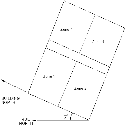
The Building North Axis is specifiedrelative to true North. Buildings frequently do not line up with true north. For convenience, one may enter surfaces in a “regular” coordinate system and then shift them via the use of the North Axis. The value is specified in degrees from “true north” (clockwise is positive).
The figure below shows how the building north axis can be rotated to correspond with one of the major axes of an actual building. The relevance of this field is described more completely under “GlobalGeometryRules”; in particular, the value of “North Axis” is ignored if a coordinate system other than “relative” is used.
Figure 1. Illustration of Building North Axis
The site’s terrain affects how the wind hits the building – as does the building height. In addition, the external conduction method usually has its own parameters for the calculation. Please see the Engineering Documentation, External Conduction section for particulars. The legal values for this field are shown in the following table.
Table 1. Values for "Terrain"
|
Terrain Type Value |
Terrain Description |
|
Country |
Flat, Open Country |
|
Suburbs |
Rough, Wooded Country, Suburbs |
|
City |
Towns, city outskirts, center of large cities |
|
Ocean |
Ocean, Bayou flat country |
|
Urban |
Urban, Industrial, Forest |
The following two fields along with the minimum and maximum number of warmup days (also in this object) define the user specified criteria for when EnergyPlus will “converge” at each environment (each sizing period or run period set as Yes in the SimulationControl object). EnergyPlus “runs” the first day of the environment (starting with a set of hard-coded initial conditions) until the loads/temperature convergence tolerance values are satisfied (next two fields) or until it reaches “maximum number of warmup days”. Note that setting the convergence tolerance values too loose will cause the program to be satisifed too early and you may not get the results you expect from the actual simulation.
This value represents the number at which the loads values must agree before “convergence” is reached. Loads tolerance value is a fraction of the load.
This value represents the number at which the zone temperatures must agree (from previous iteration) before “convergence” is reached. (Units for this field is delta C).
Convergence of the simultaneous heat balance/HVAC solution is reached when either the loads or temperature criterion is satisfied.
All tolerances have units so the temperature tolerance is in degrees C (or degrees K) and the loads tolerance is in Watts. Both tolerances work the same way, just one looks at temperatures and one looks at heating and cooling loads. After the second warm-up day, the program compares the maximum temperature experienced in a space with the maximum temperature from the previous day. If those two temperatures are within the tolerance, then it has passed the first warm-up check.
It does a similar comparison with lowest temperatures experience within all the zones. If the current simulation day and the previous day values are within the tolerance, then it has passed the second warm-up check. Similar things are done with the loads tolerance and the maximum heating and cooling loads that are experienced within the spaces. Those are compared individually to the values for the previous day. If they are both in tolerance, then the simulation has passed the third and fourth warm-up check. The simulation stays in the warm-up period until ALL FOUR checks have been passed.
Please note--other "convergence tolerance" inputs are required for certain HVAC equipment (unit ventilator, unit heater, window AC, etc.). The purpose and units of these parameters are different from "load convergence tolerance" and "temperature convergence tolerance" in the BUILDING object.
Setting this value determines how EnergyPlus treats beam solar radiation and reflectances from exterior surfaces that strike the building and, ultimately, enter the zone. There are five choices: MinimalShadowing, FullExterior and FullInteriorAndExterior, FullExteriorWithReflections, FullInteriorAndExteriorWithReflections.
MinimalShadowing
In this case, there is no exterior shadowing except from window and door reveals. All beam solar radiation entering the zone is assumed to fall on the floor, where it is absorbed according to the floor's solar absorptance. Any reflected by the floor is added to the transmitted diffuse radiation, which is assumed to be uniformly distributed on all interior surfaces. If no floor is present in the zone, the incident beam solar radiation is absorbed on all interior surfaces according to their absorptances. The zone heat balance is then applied at each surface and on the zone's air with the absorbed radiation being treated as a flux on the surface.
FullExterior, FullExteriorWithReflections
In this case, shadow patterns on exterior surfaces caused by detached shading, wings, overhangs, and exterior surfaces of all zones are computed. As for MinimalShadowing, shadowing by window and door reveals is also calculated. Beam solar radiation entering the zone is treated as for MinimalShadowing -- All beam solar radiation entering the zone is assumed to fall on the floor, where it is absorbed according to the floor's solar absorptance. Any reflected by the floor is added to the transmitted diffuse radiation, which is assumed to be uniformly distributed on all interior surfaces. If no floor is present in the zone, the incident beam solar radiation is absorbed on all interior surfaces according to their absorptances. The zone heat balance is then applied at each surface and on the zone's air with the absorbed radiation being treated as a flux on the surface.
FullInteriorAndExterior, FullInteriorAndExteriorWithReflections
This is the same as FullExterior except that instead of assuming all transmitted beam solar falls on the floor the program calculates the amount of beam radiation falling on each surface in the zone, including floor, walls and windows, by projecting the sun's rays through the exterior windows, taking into account the effect of exterior shadowing surfaces and window shading devices.
If this option is used, you should be sure that the surfaces of the zone totally enclose a space. This can be determined by viewing the eplusout.dxf file with a program like AutoDesk’s Volo View Express. You should also be sure that the zone is convex. Examples of convex and non-convex zones are shown in Figure 2. The most common non-convex zone is an L-shaped zone. (A formal definition of convex is that any straight line passing through the zone intercepts at most two surfaces.) If the zone’s surfaces do not enclose a space or if the zone is not convex you should use Solar Distribution = FullExterior instead of FullInteriorAndExterior.
If you use FullInteriorAndExterior the program will also calculate how much beam radiation falling on the inside of an exterior window (from other windows in the zone) is absorbed by the window, how much is reflected back into the zone, and how much is transmitted to the outside. In this calculation the effect of a shading device, if present, is accounted for.
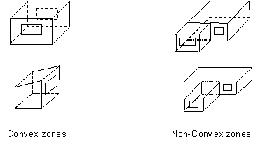
Figure 2. Illustration of Convex and Non-convex Zones
Reflection calculations
Note: Using the reflection calculations can be very time-consuming. Even error-prone. As a possible alleviation, you can use the Output:Diagnostics,DoNotMirrorDetachedShading; in many cases to get past a fatal error.
If using reflections, the program calculates beam and sky solar radiation that is reflected from exterior surfaces and then strikes the building. These reflecting surfaces fall into three categories:
1) Shadowing surfaces. These are surfaces like overhangs or neighboring buildings entered with Surface Shading:Site:Detailed, Shading:Building:Detailed, or Shading:Zone:Detailed. See Figure 3.
2) These surfaces can have diffuse and/or specular (beam-to-beam) reflectance values that are specified with the Shading Surface Reflectance object (ref: ShadingProperty:Reflectance).
3) Exterior building surfaces. In this case one section of the building reflects solar radiation onto another section (and vice-versa). See Figure 4.
4) The building surfaces are assumed to be diffusely reflecting if they are opaque (walls, for example) and specularly reflecting if they are windows or glass doors. The reflectance values for opaque surfaces are calculated by the program from the Solar Absorptance and Visible Absorptance values of the outer material layer of the surface’s construction (ref: Material properties). The reflectance values for windows and glass doors are calculated by the program from the reflectance properties of the individual glass layers that make up surface’s construction assuming no shading device is present and taking into account inter-reflections among the layers (ref: Window Properties).
5) The ground surface. Reflection from the ground is calculated even if reflections option is not used. But in this case the ground plane is considered unobstructed, i.e., the shadowing of the ground by the building itself or by obstructions such as neighboring buildings is ignored. This shadowing is taken into account if the reflections option is used.[1] This is shown in Figure 5.
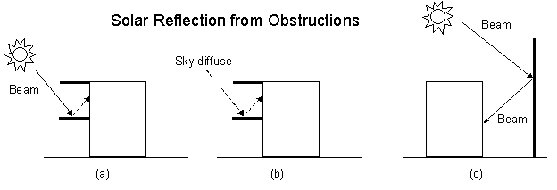
Figure 3. Solar reflection from shadowing surfaces. Solid arrows are beam solar radiation; dashed arrows are diffuse solar radiation. (a) Diffuse reflection of beam solar radiation from the top of an overhang. (b) Diffuse reflection of sky solar radiation from the top of an overhang. (c) Beam-to-beam (specular) reflection from the façade of an adjacent highly-glazed building represented by a vertical shadowing surface.
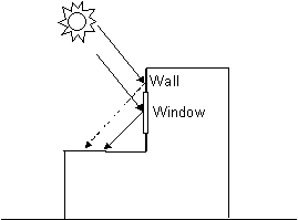
Figure 4. Solar reflection from building surfaces onto other building surfaces. In this example beam solar reflects from a vertical section of the building onto a roof section. The reflection from the window is specular. The reflection from the wall is diffuse.
Figure 5. Shadowing from building affects beam solar reflection from the ground. Beam-to-diffuse reflection from the ground onto the building occurs only for sunlit areas, A and C, not from shaded area, B.
This field specifies the number of “warmup” days that might be used in the simulation before “convergence” is achieved. The default number, 25, is usually more than sufficient for this task; however, some complex buildings (with complex constructions) may require more days. An error message will occur when the simulation “runs” out of days, fort each zone:
CheckWarmupConvergence: Loads Initialization, Zone="MAIN ZONE" did not converge after 30 warmup days.
See Warmup Convergence Information in .eio file for details
..Environment(SizingPeriod)="DENVER CENTENNIAL GOLDEN N ANN CLG 1% CONDNS DB=>MWB"
..Max Temp Comparison = 2.06E-002 vs Temperature Convergence Tolerance=0.50 – Pass Convergence
..Min Temp Comparison = 5.95E-003 vs Temperature Convergence Tolerance=0.50 – Pass Convergence
..Max Cool Load Comparison = 9.5082E-002 vs Loads Convergence Tolerance=5.00E-002 – Fail Convergence
As noted in the message, there will be more information in the .eio file. (Refer to Output Details document as well for examples.)
You may be able to increase the Maximum Number of Warmup Days and get convergence, but some anomalous buildings may still not converge. Simulation proceeds for x warmup days until “convergence” is reached (see the discussion under the Temperature Convergence Tolerance Value field in this object, just above).
The minimum number of warmup days that produce enough temperature and flux history to start EnergyPlus simulation for all reference buildings was suggested to be 6. When this field is greater than the maximum warmup days defined previous field the maximum number of warmup days will be reset to the minimum value entered here. Warmup days will be set to be the value you entered when it is less than the default 6. The selection of 6 as a minimum was done after careful study using the 400+ test suite files that we use in development.
An example from an IDF:
Building,
PSI HOUSE DORM AND OFFICES, !- Name
36.87000, !- North Axis {deg}
Suburbs, !- Terrain
0.04, !- Loads Convergence Tolerance Value
0.4000000, !- Temperature Convergence Tolerance Value {deltaC}
FullInteriorAndExterior, !- Solar Distribution
40, !- Maximum Number of Warmup Days
6; !- Minimum Number of Warmup Days
This input object is used control the choice of models used for surface convection at the inside face of all the heat transfer surfaces in the model. This object sets the selection for convection correlations in a global way. The Zone Inside Convection Algorithm input field in the Zone object may be used to selectively override this value on a zone-by-zone basis. Further, individual surfaces can refine the choice by each surface or surface lists – see object SurfaceProperty:ConvectionCoefficients and object SurfaceProperty:ConvectionCoefficients:MultipleSurface.
The model specified in this field is the default algorithm for the inside face all the surfaces.. The key choices are Simple, TARP, CeilingDiffuser, and AdaptiveConvectionAlgorithm.
The Simple model applies constant heat transfer coefficients depending on the surface orientation.
The TARP model correlates the heat transfer coefficient to the temperature difference for various orientations. This model is based on flat plate experiments.
The CeilingDiffuser model is a mixed and forced convection model for ceiling diffuser configurations. The model correlates the heat transfer coefficient to the air change rate for ceilings, walls and floors. These correlations are based on experiments performed in an isothermal room with a cold ceiling jet. To avoid discontinuities in surface heat transfer rate calculations, all of correlations have been extrapolated beyond the lower limit of the data set (3 ACH) to a natural convection limit that is applied during the hours when the system is off.
The AdaptiveConvectionAlgorithm model is an dynamic algorithm that organizes a large number of different convection models and automatically selects the one that best applies. The adaptive convection algorithm can also be customized using the SurfaceConvectionAlgorithm:Inside:AdaptiveModelSelections input object. These models are explained in detail in the EnergyPlus Engineering Reference Document. The default is AdaptiveConvectionAlgorithm.
IDF Example:
SurfaceConvectionAlgorithm:Inside,TARP;
Various exterior convection models may be selected for global use. The optional Zone Outside Convection Algorithm input field in the Zone object may be used to selectively override this value on a zone-by-zone basis. Further, individual surfaces can refine the choice by each surface or surface lists – see object SurfaceProperty:ConvectionCoefficients and object SurfaceProperty:ConvectionCoefficients:MultipleSurface.
The available key choices are SimpleCombined, TARP, MoWiTT, DOE-2, and AdaptiveConvectionAlgorithm.
The Simple convection model applies heat transfer coefficients depending on the roughness and windspeed. This is a combined heat transfer coefficient that includes radiation to sky, ground, and air. The correlation is based on Figure 1, Page 25.1 (Thermal and Water Vapor Transmission Data), 2001 ASHRAE Handbook of Fundamentals. Note that if Simple is chosen here or in the Zone field and a SurfaceProperty:ConvectionCoefficients object attempts to override the caulcation with a different choice, the action will still be one of combined calculation. To change this, you must select one of the other methods for the global default.
All other convection models apply heat transfer coefficients depending on the roughness, windspeed, and terrain of the building’s location. These are convection only heat transfer coefficients; radiation heat transfer coefficients are calculated automatically by the program.
The TARP algorithm was developed for the TARP software and combines natural and wind-driven convection correlations from laboratory measurements on flat plates.
The DOE-2 and MoWiTT were derived from field measurements. DOE-2 uses a correlation from measurements by Klems and Yazdanian for rough surfaces. MoWitt uses a correlation from measurements by Klems and Yazdanian for smooth surfaces and, therefore, is most appropriate for windows (see SurfaceProperty:ConvectionCoefficients:MultipleSurface for how to apply to only windows).
The AdaptiveConvectionAlgorithm model is an dynamic algorithm that organizes a large number of different convection models and automatically selects the one that best applies. The adaptive convection algorithm can also be customized using the SurfaceConvectionAlgorithm:Outside:AdaptiveModelSelections input object. All algorithms are described more fully in the Engineering Reference.
Note that when the surface is wet (i.e. it is raining and the surface is exposed to wind) then the convection coefficient appears as a very large number (1000) and the surface is exposed to the Outdoor Wet-bulb Temperature rather than the Outdoor Dry-bulb Temperature.
IDF Example:
SurfaceConvectionAlgorithm:Outside, AdaptiveConvectionAlgorithm;
The HeatBalanceAlgorithm object provides a way to select what type of heat and moisture transfer algorithm will be used across the building construction calculations.
Four values are allowed to select which solution will be used.
n The ConductionTransferFunction selection is a sensible heat only solution and does not take into account moisture storage or diffusion in the construction elements.
n The MoisturePenetrationDepthConductionTransferFunction selection is a sensible heat diffusion and an inside surface moisture storage algorithm that also needs additional moisture material property information. Sometimes, this is referred to as the Effective Moisture Penetration Depth or EMPD. See the moisture material property object for additional information and description of outputs:
n MaterialProperty:MoisturePenetrationDepth:Settings
n Advanced/Research usage: The ConductionFiniteDifference selection is a sensible heat only solution and does not take into account moisture storage or diffusion in the construction elements. This solution technique uses a 1-D finite difference solution in the construction elements. Outputs for the surfaces are described with the material property objects. The Conduction Finite Difference (aka CondFD) property objects are:
n MaterialProperty:PhaseChange
n MaterialProperty:VariableThermalConductivity
n Advanced/Research usage: The ConductionFiniteDifferenceSimplified selection is a sensible heat only solution and does not take into account moisture storage or diffusion in the construction elements. This solution technique uses a 1-D finite difference solution in the construction elements – representing only two nodes per construction. Outputs for the surfaces are described with the material property objects. The Conduction Finite Difference Simplified property objects are:
n MaterialProperty:VariableThermalConductivity
n Construction:UseHBAlgorithmCondFDDetailed
n Advanced/Research usage: The CombinedHeatAndMoistureFiniteElement is a coupled heat and moisture transfer and storage solution. The solution technique uses a one dimensional finite difference solution in the construction elements and requires further material properties described in the Heat and Moisture Transfer material properties objects. Outputs from the algorithm are described with these objects. The Heat and Moisture Transfer property objects are:
n MaterialProperty:HeatAndMoistureTransfer:Settings
n MaterialProperty:HeatAndMoistureTransfer:SorptionIsotherm
n MaterialProperty:HeatAndMoistureTransfer:Suction
n MaterialProperty:HeatAndMoistureTransfer:Redistribution
n MaterialProperty:HeatAndMoistureTransfer:Diffusion
n MaterialProperty:HeatAndMoistureTransfer:ThermalConductivity
This field is a bit “advanced”. It should only be used when the simulation fails AND you cannot determine a cause for the failure. That is, you receive an error similar to:
** Severe ** Temperature out of bounds (202.91) for surface=Wall1
** ~~~ ** in Zone=Zone01
** ~~~ ** Occurrence info=NEW YORK CITY NY SUMMER, 07/21 16:00 - 16:01
** ~~~ ** A temperature out of bounds problem can be caused by several things. The user
** ~~~ ** should check the weather environment, the level of internal gains with respect
** ~~~ ** to the zone, and the thermal properties of their materials among other things.
** ~~~ ** A common cause is a building with no thermal mass -- all materials with
** ~~~ ** Regular-R definitions.
And, after careful perusal, you cannot find a solution as suggested in the error description. You may then want to enter a higher number than the default for this field.
This optional field is used to set an overall minimum for the value of the coefficient for surface convection heat transfer (Hc) in W/m2-K. A minimum is necessary for numerical robustness because some correlations for Hc can result in zero values and create numerical problems. This field can be used to support specialized validation testing to suppress convection heat transfer and to investigate the implications of different minimum Hc values. The default is 0.1.
This optional field is used to set an overall maximum for the value of the coefficient for surface convection heat transfer (Hc) in W/m2-K. High Hc values are used in EnergyPlus to approximate fixed surface temperature boundary conditions. This field can be used to alter the accepted range of user-defined Hc values.
And, a default IDF example
HeatBalanceAlgorithm,ConductionTransferFunction; ! Solution Algorithm
This object is used to control the behavior of the Conduction Finite Difference algorithm for surface heat transfer. The settings are global and affect how the model behaves for all the surfaces.
This field determines the solution scheme used by the Conduction Finite Difference model. There are two options CrankNicholsonSecondOrder and FullyImplicitFirstOrder. The CrankNicholsonSecondOrder scheme is second order in time and may be faster. But it can be unstable over time when boundary conditions change abruptly and severely. The FullyImplicitFirstOrder scheme is first order in time and is more stable over time. But it may be slower.
This field controls the how the model determines spatial discretization, or the count of nodes across each material layer in the construction. The model calculates the nominal distance associated with a node, ![]() , using
, using
![]()
Where
![]() is the thermal diffusivity of the material layer, in m2/s
is the thermal diffusivity of the material layer, in m2/s
![]() is the length of the timestep in seconds.
is the length of the timestep in seconds.
C is a constant set by this field.
The default is 3. Typical values are from 1 to 3. Lower values for this constant lead to more nodes and finer-grained space discretization.
The finite difference solver includes under-relaxation for improved stability for interactions with the other surfaces. This input field can optionally be used to modify the starting value for the relaxation factor. Larger numbers may solve faster, while smaller numbers may be more stable. The default is 1.0. If the program detects numerical instability, it may reduce the value entered here to something lower and more stable.
The surface heat balance model at the inside face has a numerical solver that uses a convergence parameter for a maximum allowable differences in surface temperature. This field can optionally be used to modify this convergence criteria. The default value is 0.002 and was selected for stability. Lower values may further increase stability at the expense of longer runtimes, while higher values may decrease runtimes but lead to possible instabilities. The units are in degrees Celsius.
An example IDF object follows.
HeatBalanceSettings:ConductionFiniteDifference,
FullyImplicitFirstOrder , !- Difference Scheme
3.0 , !- Space Discretization Constant
1.0, !- Relaxation Factor
0.002 ;!- Inside Face Surface Temperature Convergence Criteria
The ZoneAirHeatBalanceAlgorithm object provides a way to select what type of solution algorithm will be used to calculate zone air temperatures and humidity ratios. This object is an optional object. If the default algorithm is used, this object is not required in an input file.
Three choices are allowed to select which solution algorithm will be used. The ThirdOrderBackwardDifference selection is the default selection and uses the third order finite difference approximation to solve the zone air energy and moisture balance equations. The AnalyticalSolution selection uses the integration approach to solve the zone air energy and moisture balance equations. The EulerMethod selection uses the first order finite backward difference approximation to solve the zone air energy and moisture balance equations.
And, a default IDF example is shown below:
ZoneAirHeatBalanceAlgorithm, ThirdOrderBackwardDifference; !- Algorithm
The ZoneAirContaminantBalance object provides a way to select which contaminant type will be simulated. Currently the only available contaminant is carbon dioxide. The ability to model other contaminants will be added later. This object is optional, only required in the input data file if the user wishes to model contaminant concentration levels as part of their simulation.
Input is Yes or No. The default is No. If Yes, simulation of carbon dioxide concentration levels will be performed. If No, simulation of carbon dioxide concentration levels will not be performed.
This field specifies the name of a schedule that contains outdoor air carbon dioxide level values in units of ppm. One source of monthly average CO2 levels in the atmosphere is available at a NOAA ftpsite as ftp://ftp.cmdl.noaa.gov/ccg/co2/trends/co2_mm_mlo.txt.
An IDF example:
ZoneAirContaminantBalance,
Yes, !- Carbon Dioxide Concentration
Outdoor CO2 Schedule; !- Outdoor Carbon Dioxide Schedule Name
The following output variable is available when Carbon Dioxide Concentration = Yes.
HVAC,Average,Zone Air Carbon Dioxide Concentration [ppm]
This report variable represents the carbon dioxide concentration level in parts per million (ppm) for each zone. This is calculated and reported from the Correct step in the Zone Air Contaminant Predictor-Corrector module.
In order to speed up the calculations, shadowing calculations (sun position, etc.) are performed over a period of days. Note that this value may be very important for determining the amount of sun entering your building and by inference the amount of cooling or heating load needed for maintaining the building. Though termed “shadowing” calculations, it in affect determines the sun position for a particular day in a weather file period simulation. (Each design day will use the date of the design day object). Even though weather file data contains the amount of solar radiation, the internal calculation of sun position will govern how that affect various parts of the building. By default, this is every 20 days throughout a weather run period.
This numeric field will cause the shadowing calculations to be done periodically using the number in the field as the number of days in each period. Using this field will allow you to synchronize the shadowing calculations with changes in shading devices. Using the default of 20 days in each period is the average number of days between significant changes in solar position angles. For these shadowing calculations, an “average” (over the time period) of solar angles, position, equation of time are also used.
This numeric field will allow you to increase the number of figures in shadow overlaps. Due to the shadowing algorithm, the number of shadows in a figure may grow quite large even with fairly reasonable looking structures. Of course, the inclusion of more allowed figures will increase calculation time. Likewise, too few figures may not result in as accurate calculations as you desire.
This is an advanced feature. Prior to V7, the internal polygon clipping method was a special case of the Weiler-Atherton method. Now, two options are available: SutherlandHodgman (default) and ConvexWeilerAtherton. Theoretically, Sutherland-Hodgman is a simpler algorithm but it works well in cases where receiving surfaces (of shadows) are non-convex. The Weiler-Atherton implementation is only accurate where both casting and receiving surfaces are convex. Warnings/severe errors are displayed when necessary. More details on polygon clipping are contained in the Engineering Reference.
Two choices are available here: SimpleSkyDiffuseModeling and DetailedSkyDiffuseModeling. SimpleSkyDiffuseModeling (default) performs a one-time calculation for sky diffuse properties. This has implications if you have shadowing surfaces with changing transmittance (i.e. not all opaque or not all transparent) during the year. The program checks to see if this might be the case and automatically selects DetailedSkyDiffuseModeling if the shading transmittance varies. Even if the transmittance doesn’t vary and the option for detailed modeling is used, that option is retained (though it will increase execution time) because you may be using EMS to vary the transmittance. When the detailed modeling is done, there will be a warning posted if the Calculation Frequency (above) is > 1.
In general (and you should also read the previous field description), if shadowing surfaces are used with the transmittance property, the user should be careful to synchronize this calculation with the scheduled occurrence of the transmittance (if any) (or use 1, which will be the most accurate but will cause more time in the calculations).
Examples of this object in IDF: (note this object must be unique in an IDF)
ShadowCalculation,1;
ShadowCalculation,1,,SutherlandHodgman,DetailedSkyDiffuseModeling;
Sometimes, messages only confuse users – especially new users. Likewise, sometimes certain report variables exist for only a certain condition but some take them at face value/name. Some features may be very important but under certain instances cause problems. Thus, we have added the diagnostic output object to be able to turn on or off certain messages, variables, and features depending on conditions.
Both fields of the Output:Diagnostics command can accept all the applicable keys. More than one object may be entered.
Allowable choices are:
DisplayAllWarnings – use this to get all warnings (except the developer warnings “DisplayZoneAirHeatBalanceOffBalance”). This key sets all other display warning values to on.
DisplayExtraWarnings – use this to get all extra warnings. An example of an extra warning is when a user enters a ceiling height or volume with the Zone object and EnergyPlus calculates something significantly different based on the entered zone geometry.
DisplayUnusedSchedules – use this to have the unused schedules (by name) listed at the end of the simulation.
DisplayUnusedObjects – use this to have unused (orphan) objects (by name) listed at the end of the simulation.
DisplayAdvancedReportVariables – use this to be able to use the “Opaque Surface Inside Face Conduction” – the name may be misleading to some. If you put in this field, then you will be able to report on this variable.
DisplayZoneAirHeatBalanceOffBalance – this is a developer diagnostic which you can turn on, if you desire.
DoNotMirrorDetachedShading – use this to turn off the automatic mirroring of detached shading surfaces. These surfaces are automatically mirrored so that the user does not need to worry about facing direction of the surface and the shading surface will shade the building as appropriate. Note that Shading:Zone:Detailed surfaces are also mirrored and there is no way to turn that “off”.
DisplayWeatherMissingDataWarnings – use this to turn on the missing data warnings from the read of the weather file.
ReportDuringWarmup – use this to allow reporting during warmup days. This can show you exactly how your facility is converging (or not) during the initial “warmup” days of the simulation. Generally, only developers or expert simulation users would need this kind of detail.
In IDF use:
Output:Diagnostics,
DisplayExtraWarnings;
There may be times when a particular input file requires additional debugging. The Output:DebuggingData object may be used to report all available node data (e.g., temperature, mass flow rate, set point, pressure, etc.). The debug data is reported to the DBG text file. The debug file first reports the node number and name, and then all available node information for each zone time step (Ref. Timestep).
The 2 fields of the Output:DebuggingData object can accept either a 1 (turn on) or any other value (turn off). Only one object may be entered.
This field turns on debug reporting when a value of 1 is entered. Any other value (usually 0) disables debug reporting.
This field allows the debug data to be reported during the warmup period. When a value of 1 is entered the data is reported at all times, even during warmup. Any other value (usually 0) disables “reporting at all time” and debug data is only reported for each environment (RunPeriod or SizingPeriod:DesignDay).
In IDF use:
Output:DebuggingData,
1,1;
The Output:PreprocessorMessage object can be used by preprocessor programs to EnergyPlus for passing certain conditions/errors that might not be detected by scripts executing the EnergyPlus system of programs. This allows EnergyPlus to intercept problems and terminate gracefully rather than the user having to track down the exact conditions.
There is no reason for a user to enter an Output:PreprocessorMessage object but you should encourage interface developers to use this feature. More than one Output:PreprocessorMessage objects may be entered. Of course, no preprocessor message objects are necessary if there is no error information to be passed.
The preprocessor name (e.g. EPMacro, ExpandObjects) is entered here. Case is retained so that messages from EnergyPlus look very similar to what a preprocessor would produce.
This is the error severity. If Fatal, EnergyPlus will terminate after showing all preprocessor messages.
Each line is limited to 100 characters and an appropriate message can be composed.
An IDF Example:
Output:PreprocessorMessage,
No Preprocessor Used, !- preprocessor name
Information, !- error severity
Illustrative Message, !- message line 1
No problems for processing; !- message line 2
And would appear in output:
Preprocessor="No Preprocessor Used" has the following Information messages:
Illustrative Message
No problems for processing
This object is an advanced feature that can be used to control the effective storage capacity of the zone. Capacitance multipliers of 1.0 indicate the capacitance is that of the (moist) air in the volume of the specified zone. This multiplier can be increased if the zone air capacitance needs to be increased for stability of the simulation or to allow modeling higher or lower levels of damping of behavior over time. The multipliers are applied to the base value corresponding to the total capacitance for the zone’s volume of air at current zone (moist) conditions.
This field is used to alter the effective heat capacitance of the zone air volume. This affects the transient calculations of zone air temperature. Values greater than 1.0 have the effect of smoothing or damping the rate of change in the temperature of zone air from timestep to timestep. Note that sensible heat capacity can also be modeled using internal mass surfaces.
This field is used to alter the effective moisture capacitance of the zone air volume. This affects the transient calculations of zone air humidity ratio. Values greater than 1.0 have the effect of smoothing, or damping, the rate of change in the water content of zone air from timestep to timestep.
This field is used to alter the effective carbon dioxide capacitance of the zone air volume. This affects the transient calculations of zone air carbon dioxide concentration. Values greater than 1.0 have the effect of smoothing or damping the rate of change in the carbon dioxide level of zone air from timestep to timestep.
The input for SimulationControl allows the user to specify what kind of calculations a given EnergyPlus simulation will perform. For instance the user may want to perform one or more of the sizing calculations but not proceed to an annual weather file simulation. Or the user might have all flow rates and equipment sizes already specified and desire an annual weather without any preceding sizing calculations. Sizing runs, even for large projects, are quickly run – they do not add much to the overall simulation time. The SimulationControl input allows all permutations of run selection by means of 5 yes/no inputs.
Only one SimulationControl object is permitted for each EnergyPlus input file. While a SimulationControl is needed to trigger sizing calculations, it is optional for other runs (design days, run periods). The actions will still be shown in the eplusout.eio file (see Output Details and Examples Document).
Input is Yes or No. The default is No. Zone Sizing (see Sizing:Zone object) performs a special calculation, using a theoretical ideal zonal system, and determines the zone design heating and cooling flow rates and loads, saving the results in the zone sizing arrays.
Input is Yes or No. The default is No. System Sizing (see Sizing:System object) also performs a special calculation that, to oversimplify, sums up the results of the zone sizing calculation and saves the results in the system sizing arrays for reporting on component size requirements. Thus, in order to perform the system sizing calculations, the zone sizing arrays need to be filled and hence the zone sizing calculations must be performed in the same run. (This requirement is enforced by the program).
Input is Yes or No. The default is No. Unlike Zone and System Sizing, Plant Sizing does not use the Zone or System sizing arrays. Plant Sizing uses the Sizing:Plant object fields and data on the maximum component flow rates. The data on component (such as coil) flow rates is saved and made available to the Plant code whether or not component autosizing is performed and whether or not zone sizing and/or system sizing is performed. Therefore, you can specify Plant Sizing without also specifying to do Zone Sizing or System Sizing calculations.
Input is Yes or No. The default is Yes. Yes implies that the simulation will be run on all the included SizingPeriod objects (i.e., SizingPeriod:DesignDay, SizingPeriod:WeatherFileDays, and SizingPeriod:WeatherFileConditionType). Note that each SizingPeriod object constitutes an “environment” and warmup convergence (see earlier topic under the Building object) will occur for each.
Input is Yes or No. The default is Yes. Yes implies the simulation will be run on all the included RunPeriod objects. Note that each RunPeriod object constitutes an “environment” and warmup convergence (see earlier topic under the Building object) will occur for each.
An IDF example:
SimulationControl,
No, !- Do Zone Sizing Calculation
No, !- Do System Sizing Calculation
No, !- Do Plant Sizing Calculation
Yes, !- Run Simulation for Sizing Periods
Yes; !- Run Simulation for Weather File Run Periods
A custom meter allows the user to group variables or meters onto a virtual meter that can be used just like a normal meter created by EnergyPlus. For consistency, the items being grouped must all be similar.
This is a user defined name for the custom meter. Names for custom meters cannot duplicate internal meter names.
A fuel type should be specified for the meter. All assignments to this meter will be checked to assure that the same fuel type is used. Additionally, this may be used in other objects (such as the Demand Limiting). Valid choices for this field are:
n Electricity
n NaturalGas
n PropaneGas
n FuelOil#1
n FuelOil#2
n Coal
n Diesel
n Gasoline
n Water
n Generic
Fuel types are generally self-explanatory. Generic is included for convenience when a custom meter is defined that doesn’t quite fit the “fuel” categories. See the examples below.
The rest of the object is filled with parameters of the key name/report variable or meter names. When a meter name is used, the key name field is left blank.
A key name field is used when the following field specifies a report variable. If the field is left blank, then all the report variables in the following field are assigned to the meter.
This field must be a valid report variable name or a valid meter name.
The decrement custom meter is very similar to the custom meter specification but additionally allows a predefined meter to be used as the “source” meter and the remaining items subtract from that predefined meter.
This is a user defined name for the custom meter. Names for custom meters cannot duplicate internal meter names.
A fuel type should be specified for the meter. All assignments to this meter will be checked to assure that the same fuel type is used. Additionally, this may be used in other objects (such as the Demand Limiting). Valid choices for this field are:
n Electricity
n NaturalGas
n PropaneGas
n FuelOil#1
n FuelOil#2
n Coal
n Diesel
n Gasoline
n Water
n Generic
This name specifies the meter that will be used as the main source for the decrement custom meter. The remainder of the fields are subtracted from the value of this meter to create the meter value named above. The Source Meter is not changed in any way by including this custom meter.
The rest of the object is filled with parameters of the key name/report variable or meter names. When a meter name is used, the key name field is left blank.
A key name field is used when the following field specifies a report variable. If the field is left blank, then all the report variables in the following field are assigned to the meter.
This field must be a valid report variable name or a valid meter name. Additionally, it must be contained on the Source Meter. Note that, if an error occurs, only the Variable in error will show – confusing things if what was entered was a meter name.
Details of the Meter:Custom/Meter:CustomDecrement are shown on the Meter Details file.
In the following examples, the custom meters are set up to illustrate the capabilities of custom meters. Custom meter “MyGeneralLights” duplicates the InteriorLights:Electricity meter. Custom meter “MyBuildingElectric” duplicates the Electricity:Building meter (by specifying that meter). Custom Meter (Decrement) “MyBuildingOther” uses the Electricity:Building meter as the source meter and subtracts out the values for MyGeneralLights (aka InteriorLights:Electricity). The resultant value for the MyBuildingOther meter should be equal to the value for the meters Electricity:Building – InteriorLights:Electricity.
Meter:Custom,
MyGeneralLights, !- Name
Electricity, !- Fuel Type
SPACE1-1, !- Key Name 1
Lights Electric Consumption, !- Report Variable or Meter Name 1
SPACE2-1, !- Key Name 2
Lights Electric Consumption, !- Report Variable or Meter Name 2
SPACE3-1, !- Key Name 3
Lights Electric Consumption, !- Report Variable or Meter Name 3
SPACE4-1, !- Key Name 4
Lights Electric Consumption, !- Report Variable or Meter Name 4
SPACE5-1, !- Key Name 5
Lights Electric Consumption; !- Report Variable or Meter Name 5
Meter:Custom,
MyBuildingElectric, !- Name
Electricity, !- Fuel Type
, !- Key Name #1
Electricity:Building; !- Report Variable or Meter Name #1
Meter:CustomDecrement,
MyBuildingOther, !- Name
Electricity, !- Fuel Type
Electricity:Building, !- Source Meter Name
, !- Key Name #1
MyGeneralLights; !- Report Variable or Meter Name #1
For an example of “generic” fuel type, one might put the Building Infiltration Heat Loss & Heat Gain on a set of custom meters:
Meter:Custom,
Building Infiltration Heat Loss, !- Name
Generic, !- Fuel Type
*, !- Key Name 1
Zone Infiltration Total Heat Loss; !- Report Variable or Meter Name 1
Meter:Custom,
Building Infiltration Heat Gain, !- Name
Generic, !- Fuel Type
*, !- Key Name 1
Zone Infiltration Total Heat Gain; !- Report Variable or Meter Name 1
One can then report these values the same way one reports other standard meters.
These appear in the eplusout.eio file. For details of the reporting, please see the Output Details and Examples document.
Not necessarily related directly to simulation, the Compliance Object group provides a repository for a group of objects that can be used directly or indirectly in reporting compliance (such as ASHRAE 90.1) to building standards.
The Compliance:Building object describes parameters related to compliance to building standards, building codes, and beyond energy code programs.
Building Rotation for Appendix G allows for the building model to be rotated for use with compliance such as ASHRAE 90.1 Appendix G. Appendix G requires the building to be rotated 0, 90, 180 and 270 degrees and the values averaged to establish baseline energy use. This input works with relative or world coordinate systems.
An example from an IDF:
Compliance:Building,
90; Building Rotation for Appendix G
This group of objects describes the ambient conditions for the simulation.
The location class describes the parameters for the building’s location. Only one location is allowed. Weather data file location, if it exists, will override any location data in the IDF. Thus, for an annual simulation, a Location does not need to be entered.
This alpha field is used as an identifying field in output reports.
This field represents the latitude (in degrees) of the facility. By convention, North Latitude is represented as positive; South Latitude as negative. Minutes should be represented in decimal fractions of 60. (15’ is 15/60 or .25)
This field represents the longitude (in degrees) of the facility. By convention, East Longitude is represented as positive; West Longitude as negative. Minutes should be represented in decimal fractions of 60. (15’ is 15/60 or .25)
This field represents the time zone of the facility (relative to Greenwich Mean Time or the 0th meridian). Time zones west of GMT (e.g. North America) are represented as negative; east of GMT as positive. Non-whole hours can be represented in decimal (e.g. 6:30 is 6.5).
This field represents the elevation of the facility in meters (relative to sea level).
Units with their abbreviations are shown in Appendix A. And, as shown in an IDF:
Site:Location, DENVER COLORADO, ! Name
39.75000 , ! Latitude {N+ S-}
-104.8700 , ! Longitude {W- E+}
-7.000000 , ! TimeZoneNumber {GMT+/-}
1610.26; ! Elevation {m}
Most examples in this document include the comment lines that illustrate each data field’s value. However, this is not necessary (though it makes the IDF more readable). The previous example could also be:
Site:Location, DENVER COLORADO,39.75,-104.87,-7,1610.26;
The design day input describes the parameters to effect a “design day” simulation, often used for load calculations or sizing equipment. Using the values in these fields, EnergyPlus “creates” a complete days’ worth of weather data (air temperatures, solar radiation, etc.) Normal operation uses the default range multipliers as shown in Figure 6 though users may choose to input their own multiplier schedule. Likewise, normal operation specifies one “humidity indicating condition” which is used to calculate the humidity ratio at maximum temperature – this is used as the constant humidity ratio for the entire day. Again, this can be overridden by specifying a relative humidity schedule or requesting generation of an hourly wet-bulb temperature profile. Multiple design days may be specified.
In the install, the “design day files” are included for the weather file locations that are included (weatherdata folder). All the design day definitions from the ASHRAE design conditions (latest publication date) are included, grouped by WMO region, on the main web site with the weather data. http://www.energyplus.gov/cfm/weather_data.cfm These files are in “macro” form but it is easy to cut and paste the appropriate definition segments. These files include the location information as well as some locations have RunPeriodControl:DaylightSavingTime objects.
This field, like the location name, is used simply for reporting and identification. This name must be unique among the SizingPeriod names entered.
This numeric field should contain the day’s maximum dry-bulb temperature in degrees Celsius. (Reference Appendix A of this document for EnergyPlus standard units and abbreviations). The MacroDataSets design day files show extreme temperature for locations as indicated in the ASHRAE HOF design condition tables.
A design day can have a “high” temperature and a “low” temperature (or can be a constant temperature for each hour of the day). If there is a difference between high and low temperatures, this field should contain the difference from the high to the low. EnergyPlus, by default, distributes this range over the 24 hours in the day as shown in the figure below:
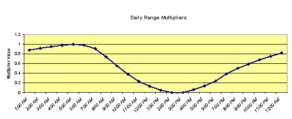
Figure 6. Default Daily range Multiplier for Design Days
The multipliers are taken from the ASHRAE 2009 HOF. More explicitly, EnergyPlus creates an air temperature for each timestep by using the entered maximum dry-bulb temperature in conjunction with the entered daily range and the above multiplier values. The actual equation used is shown below:
![]()
where
Tcurrent= Air temperature of current Hour of Day
TMax= User supplied Max Dry-bulb Temperature
Trange= User supplied Daily Temperature Range
TMultiplier= Range multiplier as shown on the above graph
The range multiplier values represent typical conditions of diurnal temperatures (i.e. the low temperature for the day occurring about 5:00 AM and the maximum temperature for the day occurring about 3:00 PM. Note that EnergyPlus does not shift the profile based on the time of solar noon as is optionally allowed in ASHRAE procedures.
ASHRAE research indicates that dry-bulb and wet-bulb temperatures typically follow the same profile, so EnergyPlus can use the default profile to generate humidity conditions (see Humidity Indicating Type = WetBulbProfileDefaultMultipliers below).
This numeric field represents the “humidity indicating” conditions that are coincident with the maximum temperature for the day. The value in this field is indicated by the key value in the field Humidity Indicating Type. This numeric value, along with the Maximum Dry-bulb Temperature and Barometric Pressure, is used to determine a humidity ratio and then used to calculate relative humidity, wet-bulb and dewpoint temperatures at each timestep. Note that this field is unnecessary when you put in a humidity indicating day schedule (described later in this section).
This numeric field is the constant barometric pressure (Pascals) for the entire day.
This numeric field is the wind speed in meters/second (constant throughout the day) for the day. The MacroDataSets design day files includes wind speed values (99.6% - heating, 1% cooling) as indicated in ASHRAE HOF design condition tables. But, you should be aware that traditional values for these are 6.7056 m/s (15 mph) for heating and 3.3528 m/s (7 mph) for cooling. A reminder is shown in the comments for the wind speed values. The comments also note the extreme wind speeds from the ASHRAE tables.
This numeric field is the source wind direction in degrees. By convention, winds from the North would have a value of 0., from the East a value of 90.
This value represents the “clearness” value for the day. This value, along with the solar position as defined by the Location information and the date entered for the design day, help define the solar radiation values for each hour of the day. Traditionally, one uses 0.0 clearness for Winter Design Days.
This numeric field indicates whether or not the building surfaces are wet. If the value is 1, then it is assumed that the building surfaces are wet. Wet surfaces may change the conduction of heat through the surface.
This numeric field indicates whether or not there is snow on the ground. If the value is 1, then it is assumed there is snow on the ground. Snow on the ground changes the ground reflectance properties.
This numeric field specifies the day of the month. That, in conjunction with the month and location information, determines the current solar position and solar radiation values for each hour of the day.
This numeric field specifies the month. That, in conjunction with the day of the month and location information, determines the current solar position and solar radiation values for each hour of the day.
This alpha field specifies the day type for the design day. This value indicates which day profile to use in schedules. For further information, see the Schedule discussion later in this document {Group -- Schedules}. Note that two of the possible day types are SummerDesignDay and WinterDesignDay – allowing the user to customize schedules for the design conditions.
This numeric field specifies whether to consider this day to be a Daylight Saving Day. This essentially adds 1 hour to the scheduling times used in items with schedules.
Valid choices here are: WetBulb, WetBulbProfileDefaultMultipliers, WetBulbProfileDifferenceSchedule, WetBulbProfileMultiplierSchedule, DewPoint, HumidityRatio, Enthalpy, and Schedule. See just below.
Allows specification a day schedule of values for relative humidity or wet-bulb profile per Humidity Indicating Type field. See below.
The Humidity Indicating fields have interacting uses and units, summarized as follows:
Table 2. Humidity Indicating Field Interactions - Design Day
|
Humidity Indicating Type |
Humidity Indicating Conditions at Maximum Dry-Bulb |
Humidity Indicating Day Schedule |
|
WetBulb |
Wet-bulb, C |
(unused) |
|
DewPoint |
Dew-point, C |
(unused) |
|
HumidityRatio |
Humidity ratio, kg/kg |
(unused) |
|
Enthalpy |
Enthalpy, kJ/kg |
(unused) |
|
WetBulbProfileDefaultMultipliers |
Wet-bulb, C |
(unused) |
|
WetBulbProfileMultiplierSchedule |
Wet-bulb, C |
Fractions of wet-bulb daily range (0 – 1) |
|
WetBulbProfileDifferenceSchedule |
Wet-bulb, C |
Difference between maximum and hour/timestep wet-bulb temperature, C |
|
Schedule |
(unused) |
Relative humidity (%, 0 – 100) |
Humidity conditions over the day are derived as follows:
WetBulb, DewPoint, HumidityRatio, or Enthalpy:
These four methods assume constant absolute humidity over the day. Calculate W = humidity ratio at Maximum Dry-Bulb Temperature and Humidity Indicating Conditions. Derive hourly/timestep humidity conditions from W and hour/timestep dry-bulb temperature.
WetBulbProfileDefaultMultipliers
Generate the wet-bulb temperature profile using Default Daily Range Multiplier for Design Days (shown in Figure 6 above) and Daily Wet-Bulb Temperature Range (below). This method is analogous to DefaultMultiplier generation of the dry-bulb temperature profile and is the procedure recommended in Chapter 14 of ASHRAE 2009 HOF.
WetBulbProfileMultiplierSchedule
Generate the wet-bulb profile using multipliers from the Humidity Indicating Day Schedule and Daily Wet-Bulb Temperature Range (below). Analogous to dry-bulb MultiplierSchedule.
WetBulbProfileDifferenceSchedule
Generate the wet-bulb profile by subtracting Humidity Indicating Day Schedule values from the daily maximum wet-bulb temperature (specified in Humidity Indicating Conditions at Maximum Dry-Bulb). Analogous to dry-bulb DifferenceSchedule.
Schedule
Hourly relative humidity is specified in Humidity Indicating Day Schedule.
In all cases, the humidity ratio is limited to saturation at the hour/timestep dry-bulb (that is, the dry-bulb temperature is used as specified, but the humidity ratio is modified as needed to be physically possible). Once a valid air state is determined, a complete set of consistent hour/timestep psychrometric values (dewpoint, wet-bulb, and enthalpy) is derived.
If you are happy with lows at 5am and highs at 3pm, you can ignore this field. If you want to specify your own temperature range multipliers (see earlier discussion at the Temperature Range field description), you can specify a type here and create a day schedule which you reference in the next field.
If you specify MultiplierSchedule in this field, then you need to create a day schedule that specifies a multiplier applied to the temperature range field (above) to create the proper dry-bulb temperature range profile for your design day.
If you specify DifferenceSchedule in this field, then you need to create a day schedule that specifies a number to be subtracted from dry-bulb maximum temperature for each timestep in the day. Note that numbers in the delta schedules cannot be negative as that would result in a higher maximum than the maximum previously specified.
If you leave this field blank or enter DefaultMultipliers, then the default multipliers will be used as shown in the “temperature range” field above.
This field is the name of a day schedule with the values as specified in the Dry-Bulb Temperature Range Modifier Type field above.
This field allows the user to select ASHRAEClearSky, ASHRAETau, ZhangHuang, or Schedule for solar modeling in the calculation of the solar radiation in the design day. ASHRAEClearSky and ZhangHuang use the Clearness value as part of their calculations. ASHRAETau invokes the revised model specified in Chapter 14 of the ASHRAE 2009 HOF and uses Taub and Taud values (below). Technical details of the models are described in the Engineering Reference. The Schedule choice allows you to enter schedule values for the day’s profile (use the next two fields for the names).
This field allows the option for you to put in your own day profile of beam solar values (wh/m2). These values will replace the calculated values during design day processing.
This field allows the option for you to put in your own day profile of diffuse solar values (wh/m2). These values will replace the calculated values during design day processing.
Optical depth for beam radiation, used only when Solar Model Indicator is ASHRAETau. See next field.
Optical depth for diffuse radiation, used only when Solar Model Indicator is ASHRAETau. Taub and Taud values are tabulated by month for 5564 locations worldwide on the CD that accompanies the ASHRAE 2009 HOF.
The difference between the maximum and minimum wet-bulb temperatures on the design day (Celsius). Used for generating daily profiles of humidity conditions when Humidity Indicating Type (above) is WetBulbProfileDefaultMultipliers or WetBulbProfileMultiplierSchedule. Values for wet-bulb temperature range are tabulated by month for 5564 locations worldwide on the CD that accompanies the ASHRAE 2009 HOF.
SizingPeriod:DesignDay,
Atlanta Jul 21 5% monthly cooling, !- Name
33.3, !- Maximum Dry-Bulb Temperature {C}
11.5, !- Daily Dry-Bulb Temperature Range {deltaC}
23.5, !- Humidity Indicating Conditions at Maximum Dry-Bulb
97620, !- Barometric Pressure {Pa}
0.0, !- Wind Speed {m/s}
0.0, !- Wind Direction {deg}
1, !- Sky Clearness
0, !- Rain Indicator
0, !- Snow Indicator
21, !- Day of Month
7, !- Month
SummerDesignDay, !- Day Type
0, !- Daylight Saving Time Indicator
WetBulbProfileDefaultMultipliers, !- Humidity Indicating Type
, !- Humidity Indicating Day Schedule
, !- Dry-Bulb Temperature Range Modifier Type
, !- Dry-Bulb Temperature Range Modifier Schedule
ASHRAETau, !- Solar Model Indicator
, !- Beam Solar Day Schedule Name
, !- Beam Solar Day Schedule Name
.556, !- ASHRAE Taub
1.779, !- ASHRAE Taud
3.5; !- Daily Wet-Bulb Temperature Range
SizingPeriod:DesignDay,
DENVER_STAPLETON Ann Htg 99% Condns DB - sched solar, !- DesignDayName
-16, !- Maximum Dry-Bulb Temperature {C}
0.0, !- Daily Dry-Bulb Temperature Range {deltaC}
-16, !- Humidity Indicating Conditions at Max Dry-Bulb
83411., !- Barometric Pressure {Pa}
2.3, !- Wind Speed {m/s}
180, !- Wind Direction {deg}
0.00, !- Sky Clearness
0, !- Rain Indicator
0, !- Snow Indicator
13, !- Day Of Month
1, !- Month
WinterDesignDay, !- Day Type
0, !- Daylight Saving Time Indicator
Wet-Bulb, !- Humidity Indicating Type
, !- Humidity Indicating Day Schedule
, !- Dry-Bulb Temperature Range Modifier Type
, !- Dry-Bulb Temperature Range Modifier Schedule
Schedule, !- Solar Model Indicator
Winter (1/13) Beam Solar,!- Beam Solar Day Schedule Name
Winter (1/13) Diffuse Solar;!- Diffuse Solar Day Schedule Name
Schedule:Day:Hourly,
Winter (1/13) Beam Solar,
Any Number,
0,0,0,0,0,0,0,190,698,852,892,919,957,953,856,700,213,0,0,0,0,0,0,0;
Schedule:Day:Hourly,
Winter (1/13) Diffuse Solar,
Any Number,
0,0,0,0,0,0,0,35,118,116,92,65,40,14,0,0,5,0,0,0,0,0,0,0;
Look at the example files 1ZoneUncontrolled_DDChanges.idf and 1ZoneUncontrolled_DD2009 for several examples of specifying Design Day inputs.
Some features may benefit by using a longer design weather period for sizing or loads calculations. Longer design periods may be created by using the SizingPeriod:WeatherFileDays or SizingPeriod:WeatherFileConditionType objects. These two objects allow for selections from an attached weather file to be used in the sizing calculations.
The SizingPeriod:WeatherFileDays object describes using a selected period from the “attached” weather file to be used in load calculations or sizing equipment. The period selected can be as small as a single day or larger. Multiple periods may be input.
This field allows for an assigned name for this run period so it can be tracked easily in sizing and other outputs.
This numeric field should contain the starting month number (1=January, 2=February, etc.) for the annual run period desired.
This numeric field should contain the starting day of the starting month (must be valid for month) for the annual run period desired.
This numeric field should contain the ending month number (1=January, 2=February, etc.) for the annual run period desired.
This numeric field should contain the ending day of the ending month (must be valid for month) for the annual run period desired.
For flexibility, the day of week indicated on the weather file can be overridden by this field’s value. Valid days of the week (Sunday, Monday, Tuesday, Wednesday, Thursday, Friday, Saturday) or special days (SummerDesignDay, WinterDesignDay, CustomDay1, CustomDay2) must be entered in this field. To clarify, this value will be used as the Start Day (type) for this sizing period. When weekdays are used, each subsequent day in the period will be incremented. When SummerDesignDay, WinterDesignDay, CustomDay1, CustomDay2 – are used, the day type will be applied for the entire period.
Weather files can contain indicators of Daylight Saving Period days. For flexibility, you may want to ignore these designations on the weather file. This field should contain the word Yes if you will accept daylight saving period days as contained on the weather file (note: not all weather files may actually have this period) or No if you wish to ignore Daylight Saving Period days that may be on the weather file.
Note that a blank or null field in this field will indicate Yes.
Weather files can contain “rain” and “snow” indicators. (EPW field “Present Weather Codes” – described in the AuxiliaryPrograms document). In turn, rain indicates wet surfaces which changes the film convection coefficient for the surface. Other models may use rain as well (Ground Heat Exchangers). Snow indicators can change the ground reflectance if there is snow on the ground. Entering “Yes” in this field allows the weather file conditions to represent “Rain” and “Snow”; entering “No” in the field “turns off” the rain/snow indicators for this period. You might use this to be able to compare two “same location” weather files of different years, origins, etc.
IDF Example:
SizingPeriod:WeatherFileDays,
Summer including Extreme Summer days, !- Name
7,18,7,25, !- Begin/end Day/Month
SummerDesignDay, !- Day type
No, !- Use Weather File Daylight Saving Period
No; !- Use Weather File Rain and Snow Indicators
SizingPeriod:WeatherFileDays,
Winter including Extreme Winter days, !- Name
1,25,2,1, !- Begin/end Day/Month
WinterDesignDay, !- Day type
No, !- Use Weather File Daylight Saving Period
No; !- Use Weather File Rain and Snow Indicators
When the EPW files are created, a heuristic procedure identifies extreme and typical periods in the actual weather file. This object will allow one of those periods to be selected for sizing or load calculations (typically). Multiple objects may be input.
This field allows for an assigned name for this run period so it can be tracked easily in sizing and other outputs.
This field allows the generic period calculated from the weather file to be selected for this run period. It is not completely generic as there may be extreme cold periods in some weather files but extreme wet periods (tropical) in others. Not all weather files have all of the valid choices. The choices for this field are:
n SummerExtreme
n SummerTypical
n WinterExtreme
n WinterTypical
n AutumnTypical
n SpringTypical
n WetSeason
n DrySeason
n NoDrySeason
n NoWetSeason
n TropicalHot
n TropicalCold
For flexibility, the day of week indicated on the weather file can be overridden by this field’s value. Valid days of the week (Sunday, Monday, Tuesday, Wednesday, Thursday, Friday, Saturday) or special days (SummerDesignDay, WinterDesignDay, CustomDay1, CustomDay2) must be entered in this field. To clarify, this value will be used as the Start Day (type) for this sizing period. When weekdays are used, each subsequent day in the period will be incremented. When SummerDesignDay, WinterDesignDay, CustomDay1, CustomDay2 – are used, the day type will be applied for the entire period.
Weather files can contain indicators of Daylight Saving Period days. For flexibility, you may want to ignore these designations on the weather file. This field should contain the word Yes if you will accept daylight saving period days as contained on the weather file (note: not all weather files may actually have this period) or No if you wish to ignore Daylight Saving Period days that may be on the weather file.
Note that a blank or null field in this field will indicate Yes.
Weather files can contain “rain” and “snow” indicators. (EPW field “Present Weather Codes” – described in the AuxiliaryPrograms document). In turn, rain indicates wet surfaces which changes the film convection coefficient for the surface. Other models may use rain as well (Ground Heat Exchangers). Snow indicators can change the ground reflectance if there is snow on the ground. Entering “Yes” in this field allows the weather file conditions to represent “Rain” and “Snow”; entering “No” in the field “turns off” the rain/snow indicators for this period. You might use this to be able to compare two “same location” weather files of different years, origins, etc.
IDF Example:
SizingPeriod:WeatherFileConditionType,
Extreme Summer Weather Period for Design, !- Name
SummerExtreme, !- Period Selection
SummerDesignDay, !- Day Type
No, !- Use Weather File Daylight Saving Period
No; !- Use Weather File Rain and Snow Indicators
SizingPeriod:WeatherFileConditionType,
Extreme Winter Weather Period for Design, !- Name
WinterExtreme, !- Period Selection
WinterDesignDay, !- Day Type
No, !- Use Weather File Daylight Saving Period
No; !- Use Weather File Rain and Snow Indicators
The RunPeriod object describes the elements necessary to create a weather file simulation. Multiple run periods may be input. EnergyPlus accepts weather files in the special EnergyPlus weather format (described below in this document). These files can describe Daylight Saving Time periods as well as holidays within their definitions. The RunPeriod object allows the user to override the use of both the Daylight Saving Period (i.e. use or ignore) and holidays that are embedded within the weather file. Note that the weather file also may contain design condition information, typical and extreme period information, ground temperatures based on air temperature calculations.
This optional field allows the RunPeriod to be named for output reporting. When left blank, the weather file location name is used.
This numeric field should contain the starting month number (1=January, 2=February, etc.) for the annual run period desired.
This numeric field should contain the starting day of the starting month (must be valid for month) for the annual run period desired.
This numeric field should contain the ending month number (1=January, 2=February, etc.) for the annual run period desired.
This numeric field should contain the ending day of the ending month (must be valid for month) for the annual run period desired.
For flexibility, the day of week indicated on the weather file can be overridden by this field’s value. Valid days of the week (Sunday, Monday, Tuesday, Wednesday, Thursday, Friday, Saturday) must be entered in this field. To clarify, this value will be used as the Start Day (type) for this run period and subsequent days will be implemented. If a blank or UseWeatherFile is entered here, then the starting day type will be calculated from the weather file (ref: Auxiliary Programs document about Data Periods).
Weather files can contain holiday designations or other kinds of special days. These day types cause a corresponding day’s schedule (see SCHEDULE definitions below) to be used during that day. This field should contain the word Yes if holidays or other special days indicated directly on the weather file should retain their “day type” or No if holidays or other special days on the weather file should be ignored. Reference the RunPeriodControl:SpecialDays object below to enter your own special days and holidays.
Note that a blank or null field in this field will indicate Yes.
Weather files can contain indicators of Daylight Saving period days. For flexibility, you may want to ignore these designations on the weather file. This field should contain the word Yes if you will accept daylight saving period days as contained on the weather file (note: not all weather files may actually have this period) or No if you wish to ignore Daylight Saving period days that may be on the weather file.
Note that a blank or null field in this field will indicate Yes.
In some countries (notably the US), when holidays fall on weekends, they are often observed on a weekday close to the holiday day. (Usually if the specific day falls on a Saturday, the observed day is Friday; if on a Sunday, the observed day is Monday). EnergyPlus will represent this custom using the value in this field. If the field is Yes, then specific date holidays that have a duration of one day, will be “observed” on the Monday after the day. (Specific day holidays are such as January 1 – a day-month combination). If the field is blank or No, then the holiday will be shown on the day-month as entered. As this option is listed at the RunPeriod, all applicable special days for the run will use the rule – there is no override for individual special days.
Note that a blank or null field in this field will indicate No.
Note: EnergyPlus processed weather files available on the EnergyPlus web site: http://www.energyplus.gov/cfm/weather_data.cfm have neither special days specified nor daylight saving period. However, DDY (Design Day) files produced from the ASHRAE Design Conditions that accompany the EPW files may include a DaylightSavingPeriod object for certain locations.
Weather files can contain “rain” indicators. (EPW field “Present Weather Codes” – described in the AuxiliaryPrograms document). In turn, rain indicates wet surfaces which changes the film convection coefficient for the surface. Other models may use rain as well (Ground Heat Exchangers). Entering “Yes” in this field allows the weather file conditions to represent “Rain”; entering “No” in the field “turns off” the rain indicator for this period. You might use this to be able to compare two “same location” weather files of different years, origins, etc.
Weather files can contain “snow” indicators. (EPW field “Snow Depth” > 0 indicates “Snow on the ground”). In turn, snow changes the reflectivity of the ground and cascades changes of this reflectivity. Entering “Yes” in this field allows the weather file conditions to represent “Snow”; entering “No” in the field “turns off” the snow indicator for this period. You might use this to be able to compare two “same location” weather files of different years, origins, etc.
This numeric field represents the number of times (usually years) the simulation has to be carried out in a multi runperiod simulation. The default value is set to 1. The number of years of simulation, in case of a Ground Loop Heat Exchanger (GLHE) simulation, should be equal to the length of simulation field in GLHE object. Note that you can specify a number of simulation years with a shorter run period (e.g. 1 week) and EnergyPlus will repeat the simulation of the shorter run period for that many times.
And, as shown in an IDF:
RunPeriod, ! Winter Simulation
Winter Simulation, !- Name
12, !- Begin Month
1, !- Begin Day of Month
3, !- End Month
31, !- End Day of Month
UseWeatherFile, !- Day of Week for Start Day
Yes, !- Use Weather File Holidays and Special Days
Yes, !- Use Weather File Daylight Saving Period
No, !- Apply Weekend Holiday Rule
Yes, !- Use Weather File Rain Indicators
Yes; !- Use Weather File Snow Indicators
! Multiple year simulation example
RunPeriod,
Multiple Years, !- Name
1, !- Begin Month
1, !- Begin Day of Month
12, !- End Month
31, !- End Day of Month
UseWeatherFile, !- Day of Week for Start Day
Yes, !- Use Weather File Holidays and Special Days
Yes, !- Use Weather File Daylight Saving Period
No, !- Apply Weekend Holiday Rule
Yes, !- Use Weather File Rain Indicators
Yes, !- Use Weather File Snow Indicators
3; !- Number of Times Runperiod to be Repeated
For weather file run periods, special day run periods can be described. These will always be in effect for the selected days in the run period. Depending on the Use Special Days value in the RunPeriod object, these can augment any special days included on the weather file.
Note: EnergyPlus processed weather files available on the EnergyPlus web site: http://www.energyplus.gov/cfm/weather_data.cfm have neither special days specified nor daylight saving period. However, DDY (Design Day) files produced from the ASHRAE Design Conditions that accompany the EPW files may include a DaylightSavingPeriod object for certain locations.
This alpha field is the title for the special day period. It must be unique among all the special day period objects entered.
This field is the starting date for the special day period. Dates in this field can be entered in several ways as shown in the accompanying table:
Table 3. Date Field Interpretation
|
Field Contents |
Interpretation |
|
<number> / <number> |
Month / Day |
|
<number> Month |
Day and Month |
|
Month <number> |
Day and Month |
|
<number> Weekday in Month |
Numbered weekday of month |
|
Last Weekday In Month |
Last weekday of month |
In the table, Month can be one of (January, February, March, April, May, June, July, August, September, October, November, December). Abbreviations of the first three characters are also valid.
In the table, Weekday can be one of (Sunday, Monday, Tuesday, Wednesday, Thursday, Friday, Saturday). Abbreviations of the first three characters are also valid.
This numeric field specifies how long (number of days) the special day period lasts.
This alpha field designates the “day type” for schedule use during the special period. It must be one of (Holiday, SummerDesignDay, WinterDesignDay, CustomDay1, CustomDay2).
An example in the IDF would be:
RunPeriodControl:SpecialDays, President’s Day, 3rd Monday in February,1,Holiday;
RunPeriodControl:SpecialDays, Thanksgiving, 4th Thursday in November, 1,Holiday;
RunPeriodControl:SpecialDays, Halloween, 10/31, 1, Holiday;
RunPeriodControl:SpecialDays, Vacation, 5/1, 14, CustomDay1;
Similar to a special day period, a daylight saving period may be entered to be applied to weather file run periods. These will always be in effect, regardless of the value entered on the RunPeriod object. Note that this period will always override any daylight saving period specified in a weather file.
Note: EnergyPlus processed weather files available on the EnergyPlus web site: http://www.energyplus.gov/cfm/weather_data.cfm have neither special days specified nor daylight saving period.
Note: For EnergyPlus Output:Variable and Output:Meter reporting, the time stamps are always in standard time. When daylight saving time is active, scheduled loads and controls will shift one hour relative to standard time.
This is the starting date of the daylight saving period. Note that it can be entered in several formats as shown in Table 3. Date Field Interpretation.
This is the ending date of the daylight saving period. Note that it can be entered in several formats as shown in Table 3. Date Field Interpretation.
And in the IDF:
! U.S. Standard for Daylight Saving
RunPeriodControl:DaylightSavingTime,2nd Sunday in March, 1st Sunday in November; !2007
! Brazil standard
RunPeriodControl:DaylightSavingTime,1st Sunday in October, Last Sunday in February;
! European Standard
RunPeriodControl:DaylightSavingTime, Last Sunday in March, Last Sunday in October;
! Syria Standard
RunPeriodControl:DaylightSavingTime, 4/1, 10/1;
Of course, these could not all appear in the same IDF as only one DaylightSavingPeriod object per input file is allowed. More information on Daylight Saving Periods can be seen on the web at: http://www.webexhibits.org/daylightsaving/ The ASHRAE Handbook of Fundamentals [ASHRAE 2005] also contains information about daylight saving periods and their climatic information now includes start and end dates for many locations.
Sky Temperature, or radiative sky temperature, is internally calculated by EnergyPlus using an algorithm using horizontal infrared radiation from sky, cloudiness factors and current temperaure. The algorithm is fully described in the Engineering Reference document. For flexibility, the following object can be entered to override the internal calculations. Much of the literature describes the sky temperature as relative to either drybulb or dewpoint temperature.
This name references an existing design period (i.e., SizingPeriod:DesignDay, SizingPeriod:WeatherFileDays, or SizingPeriod:WeatherFileConditionType) or run period (by name or blank for all run periods).
Allowable entries here are: ScheduleValue, DifferenceScheduleDryBulbValue, or DifferenceScheduleDewPointValue. In each case the following field must specify a valid schedule name. ScheduleValue – the values in the schedule are used as the sky temperature. DifferenceScheduleDryBulbValue – the values in the schedule are used as a difference to the drybulb temperature value (+values would then be greater than the drybulb temperature, -values would then be less than the drybulb temperature) for the resulting sky temperature value. DifferenceScheduleDewPointValue – the values in the schedule are used as a difference to the dewpoint temperature value (+values would then be greater than the dewpoint temperature, -values would then be less than the dewpoint temperature) for the resulting sky temperature value.
This field specifies a schedule name to accomplish the sky temperature calculation from the previous field. A Schedule:Day:* (i.e., Schedule:Day:Hourly, Schedule:Day:Interval, Schedule:Day:List) should be specified if the name in the name field matches a SizingPeriod:DesignDay object. If the name is one of the weather file period specifications (i.e. matches a SizingPeriod:WeatherFileDays, SizingPeriod:WeatherFileConditionType or RunPeriod), then the schedule name must match a full year schedule (i.e. Schedule:Year, Schedule:Compact, Schedule:File, or Schedule:Constant).
An example of IDF usage (with DesignDay):
SizingPeriod:DesignDay,
DENVER_STAPLETON Ann Clg 1% Sky Temperature modfier, !- Name
32.6, !- Maximum Dry-Bulb Temperature {C}
15.2, !- Daily Temperature Range {deltaC}
15.5, !- Humidity Indicating Conditions at Maximum Dry-Bulb
83411., !- Barometric Pressure {Pa}
4, !- Wind Speed {m/s}
120, !- Wind Direction {deg}
1.00, !- Sky Clearness
0, !- Rain Indicator
0, !- Snow Indicator
25, !- Day of Month
7, !- Month
SummerDesignDay, !- Day Type
0, !- Daylight Saving Time Indicator
WetBulb, !- Humidity Indicating Type
, !- Relative Humidity Day Schedule Name
deltaschedule, !- Dry-Bulb Temperature Range Modifier Type
temp range deltas; !- Dry-Bulb Temperature Range Modifier Schedule Name
WeatherProperty:SkyTemperature,
DENVER_STAPLETON Ann Clg 1% Sky Temperature modfier, !- Name
ScheduleValue, !- Calculation Type
DaySchedule5; !- Schedule Name
Schedule:Day:Interval,
DaySchedule5, !- Name
Temperature, !- Schedule Type Limits Name
Yes, !- Interpolate to Timestep
until: 24:00, !- Time 1
5; !- Value Until Time 1
The Site:WeatherStation object is used to specify the measurement conditions for the climatic data listed in the weather file. These conditions indicate the height above ground of the air temperature sensor, the height above ground of the wind speed sensor, as well as coefficients that describe the wind speed profile due to the terrain surrounding the weather station. There are necessary correlations between the entries for this object and some entries in the Building object, specifically the Terrain field.
Weather stations throughout the world (ref: WMO – World Meteorological Organization) take their measurements at standard conditions:
§ Air temperature is measured at approximately 1.5 m above ground
§ Wind speed is measured at 10 m above ground
§ Weather station is in a flat, open field with little protection from the wind.
When using weather data from standard sources (e.g., TMY2, IWEC, TMY, or ASHRAE design day data), it is not necessary to use the Site:WeatherStation object. However, if you are using custom weather data or real-time weather data, you may need to read and understand the concepts in the Site:WeatherStation object.
The measurement conditions at the weather station (i.e., the weather file) are used by EnergyPlus in conjunction with the Terrain field of the Building object, or optionally with the Site:HeightVariation object (see below), to calculate the local variation in atmospheric properties as a function of height above ground. Outdoor air temperature decreases with height, while wind speed increases with height. The algorithms for this calculation are in the Engineering Reference.
The Site:WeatherStation object is useful when working with a custom weather file that includes data that were not measured at the WMO standard conditions. For example, the weather data could be measured on site, or on the roof top of a nearby building. The wind speed profile coefficients can be estimated from the table below or calculated beforehand using more sophisticated techniques such as CFD modeling of the weather station terrain.
Table 4. Wind Speed Profile Coefficients (ASHRAE Fundamentals 2005).
|
Terrain Description |
Exponent |
Boundary Layer Thickness (m) |
|
Flat, open country |
0.14 |
270 |
|
Rough, wooded country |
0.22 |
370 |
|
Towns and cities |
0.33 |
460 |
|
Ocean |
0.10 |
210 |
|
Urban, industrial, forest |
0.22 |
370 |
If the Site:WeatherStation object is omitted from the input file, the WMO standard measurement conditions are assumed.
The height [m] above ground for the wind speed sensor.
The wind speed profile exponent for the terrain surrounding the weather station. The exponent can be estimated from the table above or calculated beforehand using more sophisticated techniques, such as CFD modeling of the weather station terrain.
The wind speed profile boundary layer thickness [m] for the terrain surrounding the weather station. The boundary layer can be estimated from the table above or calculated beforehand using more sophisticated techniques, such as CFD modeling of the weather station terrain.
The height [m] above ground for the air temperature sensor.
For example, if you are using weather data measured on the top of your building, you should set the Wind Sensor Height Above Ground and the Air Temperature Sensor Height Above Ground to equal the height of your building (say 30 m). The Wind Speed Profile Exponent and Wind Speed Profile Boundary Layer Thickness should be set to match the values associated with the Terrain field of the Building object, or the equivalent fields of the Site:HeightVariation object.
Or, in IDF terms, with a building in a town or city:
Site:WeatherStation,
30, !- Wind Sensor Height Above Ground {m}
0.33, !- Wind Speed Profile Exponent {}
460, !- Wind Speed Profile Boundary Layer Thickness {m}
30; !- Air Temperature Sensor Height Above Ground {m}
This would change if you had a different wind speed profile exponent or wind speed profile boundary layer thickness at your site.
The Site:HeightVariation object is used to specify the local variation in atmospheric properties at the site and should be used only if you require advanced control over the height-dependent variations for wind speed and temperature. The coefficients set by this object are used by EnergyPlus, in conjunction with the Site:WeatherStation object (see above), to calculate the local variation in atmospheric properties as a function of height above ground. Outdoor air temperature decreases with height, while wind speed increases with height. The local outdoor air temperature and wind speed are calculated separately for all zones and surfaces, and optionally for outdoor air nodes for which a height has been specified (see OutdoorAir:Node object). With the default inputs, wind speed falls significantly at heights lower than the weather station measurement height, and temperature increases slightly. The algorithms for this calculation are in the Engineering Reference. There are necessary correlations between the entries for this object and some entries in the Building object, specifically the Terrain field.
Table 5. Atmospheric Variables at Two Different Heights Above Ground Level.
|
Variable |
1.5 m |
284 m |
Absolute Diff |
Percent Diff |
|
Air Temperature |
15°C |
13.15°C |
1.85°C |
12.3% |
|
Barometric Pressure |
101,325 Pa |
97,960 Pa |
3,365 Pa |
3.3% |
|
Wind Speed |
2.46 m/s |
7.75 m/s |
5.29 m/s |
215% |
Note that using this object overrides the wind speed profile coefficients implied by the Terrain field of the Building object even if the wind speed profile fields are left blank. The wind speed profile coefficients can be estimated from the table above (see Site:WeatherStation) or calculated beforehand using more sophisticated techniques such as CFD modeling of the site terrain.
The wind speed profile exponent for the terrain surrounding the site. The exponent can be estimated from the table above (see Site:WeatherStation) or calculated beforehand using more sophisticated techniques, such as CFD modeling of the site terrain. Note that using this object overrides the wind speed profile coefficients implied by the Terrain field of the Building object even if this field is left blank.
The wind speed profile boundary layer thickness [m] for the terrain surrounding the site. The boundary layer can be estimated from the table above (see Site:WeatherStation) or calculated beforehand using more sophisticated techniques, such as CFD modeling of the site terrain. Note that using this object overrides the wind speed profile coefficients implied by the Terrain field of the Building object even if this field is left blank. This field can be set to zero to turn off all wind dependence on height.
The air temperature gradient coefficient [K/m] is a research option that allows the user to control the variation in outdoor air temperature as a function of height above ground. The real physical value is 0.0065 K/m. This field can be set to zero to turn off all temperature dependence on height. Note that the Air Temperature Sensor Height in the Site:WeatherStation object should also be set to zero in order to force the local outdoor air temperatures to match the weather file outdoor air temperature. This change is required because the Site:WeatherStation object assumes an air temperature gradient of 0.0065 K/m.
Site:HeightVariation,
0.22, !- Wind Speed Profile Exponent
370, !- Wind Speed Profile Boundary Layer Thickness {m}
0.0065; !- Air Temperature Gradient Coefficient {deltaC/m}
Ground temperatures are used for the ground heat transfer model. There can be only one ground temperature object included, and it is used as the outside surface temperature for all surfaces with Outside Boundary Condition=Ground. The object is options if you have no surfaces with ground contact. The outside surface temperature for individual surfaces can be specified using the OtherSideCoefficients (ref: SurfaceProperty:OtherSideCoefficients) object that allows Toutside to be set with a schedule. This permits using any number of different outside face temperatures in addition to the ground temperature.
Caution: The “undisturbed” ground temperatures calculated by the weather converter should not be used in building losses but are appropriate to be used in the Site:GroundTemperature:Shallow and Site:GroundTemperature:Deep objects. The reasoning (for building losses) is that these values are too extreme for the soil under a conditioned building. For best results, use the Slab or Basement program described in this document to calculate custom monthly average ground temperatures (see the Ground Heat Transfer section). This is especially important for residential applications and very small buildings. If one of these ground temperature preprocessors is not used, for typical commercial buildings in the USA, a reasonable default value is 2C less than the average indoor space temperature.
More information about determining appropriate ground temperatures is given in the Auxiliary Programs document.
Each numeric field is the monthly ground temperature (degrees Celsius) used for the indicated month (January=1st field, February=2nd field, etc.)
An IDF example:
Site:GroundTemperature:BuildingSurface,19,20,20,20,20,20,20,20,20,20,20,20;
Site:GroundTemperature:Shallow are used by the Surface Ground Heat Exchanger (i.e. object: GroundHeatExchanger:Surface). Only one shallow ground temperature object can be included.
Note that the ground temperatures included in full year weather files may be suitable of being used for the values in these fields – namely, the .5 m depth temperatures that are calculated for “undisturbed” soil of “typical” conditions. However, you may wish to use some other change effect – based on the weather conditions of the building location.
Each numeric field is the monthly surface ground temperature (degrees Celsius) used for the indicated month (January=1st field, February=2nd field, etc.)
An IDF example:
Site:GroundTemperature:Shallow, 4,4,6,6,10,10,15,15,14,14,8,8;
Site:GroundTemperature:Deep are used by the Pond Ground Heat Exchanger and Vertical Ground Heat Exchanger objects (i.e. objects: GroundHeatExchanger:Pond and GroundHeatExchanger:Vertical). Only one deep ground temperature object can be included.
Note that the ground temperatures included in full year weather files may be suitable of being used for the values in these fields – namely, the 4 m depth temperatures that are calculated for “undisturbed” soil of “typical” conditions. However, you may wish to use some other change effect – based on the weather conditions or special knowledge of the building location.
Each numeric field is the monthly deep ground temperature (degrees Celsius) used for the indicated month (January=1st field, February=2nd field, etc.)
An IDF example:
Site:GroundTemperature:Deep, 16,16,16,16,16,16,16,16,16,16,16,16;
Site:GroundTemperature:FCfactorMethod is used only by the underground walls or slabs-on-grade or underground floors defined with C-factor (Construction:CfactorUndergroundWall) and F-factor (Construction:FfactorGroundFloor) method for code compliance calculations where detailed construction layers are unknown. Only one such ground temperature object can be included. The monthly ground temperatures for this object are close to the monthly outside air temperatures delayed by three months. If user does not input this object in the IDF file, it will be defaulted to the 0.5m set of monthly ground temperatures from the weather file if they are available. Entering these will also overwrite any ground temperatures from the weather file in the F and C factor usage. If neither is available, an error will result.
Each numeric field is the monthly ground temperature (degrees Celsius) used for the indicated month (January=1st field, February=2nd field, etc.)
And, the IDF example:
Site:GroundTemperature:FCfactorMethod, 9.5, 3.5, -0.7, -1.7, -0.6, 3.6, 9.3, 14, 18.2, 22.7, 21.2, 16.8;
Ground reflectance values are used to calculate the ground reflected solar amount. This fractional amount (entered monthly) is used in this equation:
![]()
Of course, the Ground Reflected Solar is never allowed to be negative. The ground reflectance can be further modified when snow is on the ground by the Snow Ground Reflectance Modifier. To use no ground reflected solar in your simulation, enter 0.0 for each month.
Each numeric field is the monthly average reflectivity of the ground used for the indicated month (January=1st field, February=2nd field, etc.)
And use in an IDF:
Site:GroundReflectance,
0.600, !January Ground Reflectance
0.600, !February Ground Reflectance
0.400, !March Ground Reflectance
0.300, !April Ground Reflectance
0.200, !May Ground Reflectance
0.200, !June Ground Reflectance
0.200, !July Ground Reflectance
0.200, !August Ground Reflectance
0.200, !September Ground Reflectance
0.200, !October Ground Reflectance
0.300, !November Ground Reflectance
0.400; !December Ground Reflectance
It is generally accepted that snow resident on the ground increases the basic ground reflectance. EnergyPlus allows the user control over the snow ground reflectance for both “normal ground reflected solar” calculations (see above) and snow ground reflected solar modified for daylighting. These are entered under this object and both default to 1 (same as normal ground reflectance – no special case for snow which is a conservative approach).
This field is a decimal number which is used to modified the basic monthly ground reflectance when snow is on the ground (from design day input or weather data values).
![]()
The actual Ground Reflectance is limited to [0.0,1.0].
This field is a decimal number which is used to modified the basic monthly ground reflectance when snow is on the ground (from design day input or weather data values).
![]()
The actual Ground Reflectance is limited to [0.0,1.0].
An IDF example:
Site:GroundReflectance:SnowModifier,
1.0; !- Ground Reflected Solar Modifier
Outputs will show both the inputs from the above object as well as monthly values for both Snow Ground Reflectance and Snow Ground Reflectance for Daylighting.
The Site:WaterMainsTemperature object is used to calculate water temperatures delivered by underground water main pipes. The mains temperatures are used as default, make-up water temperature inputs for several plant objects, including: WaterUse:Equipment, WaterUse:Connections, WaterHeater:Mixed and WaterHeater:Stratified. The mains temperatures are also used in the water systems objects to model the temperature of cold water supplies.
Water mains temperatures are a function of outdoor climate conditions and vary with time of year. A correlation has been formulated to predict water mains temperatures based on two weather inputs:
· average annual outdoor air temperature (dry-bulb)
· maximum difference in monthly average outdoor air temperatures
These values can be easily calculated from annual weather data using a spreadsheet or from the ".stat" file available with the EnergyPlus weather files at www.energyplus.gov. Monthly statistics for dry-bulb temperatures are shown with daily averages. The daily averages are averaged to obtain the annual average. The maximum and minimum daily average are subtracted to obtain the maximum difference. For more information on the water mains temperatures correlation, see the EnergyPlus Engineering Document.
Alternatively, the Site:WaterMainsTemperature object can read values from a schedule. This is useful for measured data or when water comes from a source other than buried pipes, e.g., a river or lake.
If there is no Site:WaterMainsTemperature object in the input file, a default constant value of 10 C is assumed.
This field selects the calculation method and must have the keyword Schedule or Correlation.
If the calculation method is Schedule, the water mains temperatures are read from the schedule referenced by this field. If the calculation method is Correlation, this field is ignored.
If the calculation method is Correlation, this field is used in the calculation as the annual average outdoor air temperature (dry-bulb) [C]. If the calculation method is Schedule, this field is ignored.
If the calculation method is Correlation, this field is used in the calculation as the maximum difference in monthly average outdoor air temperatures [∆C]. If the calculation method is Schedule, this field is ignored.
Site:WaterMainsTemperature,
Correlation, !- Calculation Method {SCHEDULE | CORRELATION}
, !- Schedule Name
9.69, !- Annual Average Outdoor Air Temperature {C}
28.1; !- Maximum Difference In Monthly Average Outdoor Air Temperatures
!- {deltaC}
The Site:Precipitation object is used to describe the amount of water precipitation at the building site over the course of the simulation run period. Precipitaition includes both rain and the equivalent water content of snow. Precipitation is not yet described well enough in the usual building weather data file. So this object is used to provide the data using Schedule objects that define rates of precipitation in meters per hour.
A set of schedules for site precipitation have been developed for USA weather locations and are provided with EnergyPlus in the data set called PrecipitationSchedulesUSA.idf. The user can develop schedules however they want. The schedules in the data set were developed using EnergyPlus’ weather file (EPW) observations and the average monthly precipitation for the closest weather site provided by NOAA. EPW files for the USA that were based on TMY or TMY2 include weather observations for Light/Moderate/Heavy rainfall, however most international locations do not include these observations. The values were modeled by taking the middle of the ranges quoted in the EPW data dictionary. The assumed piecewise function is shown below.
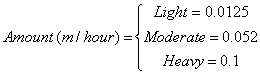
The values were inserted on hour by hour basis for the month based on the observations. Then each month was rescaled to meet the average precipitation for the month based on the 30-year average (1971-2000) provided by the NOAA/NCDC. Therefore, the flags in the EPW file match the precipitation schedules for the USA. Note that summing the average monthly precipitation values will not give you the average yearly precipitiation. The resulting value may be lower or higher than the average yearly value.
Once the typical rainfall pattern and rates are scheduled, the Site Precipitation object provides a method of shifting the total rainfall up or down for design purposes. Wetter or drier conditions can be modeled by changing the Design Annual Precipitation although the timing of precipitation throughout the year will not be changed.
Choose rainfall modeling options. Only available option is ScheduleAndDesignLevel.
Magnitude of total precipitation for an annual period to be used in the model. Value selected by the user to correspond with the amount of precipitation expected or being assumed for design purposes. The units are in meters. This field works with the following two fields to allow easily shifting the amounts without having to generate new schedules.
Name of a schedule defined elsewhere that describes the rate of precipitation. The precipitation rate schedule is analogous to weather file data. However, weather files for building simulation do not currently contain adequate data for such calculations. Therefore, EnergyPlus schedules are used to enter the pattern of precipitation events. The values in this schedule are the average rate of precipitation in meters per hour. The integration of these values over an annual schedule should equal the nominal annual precipitation.
Magnitude of annual precipitation associated with the rate schedule. This value is used to normalize the precipitation.
IDF example:
Site:Precipitation,
ScheduledAndDesignLevel, !- Precipitation Model Type
0.75, !- Design Level Total Annual Precipitation {m/yr}
PrecipitationSchd, !- Schedule Name for Precipitation Rates
0.80771; !- Average Total Annual Precipitation {m/yr}
The RoofIrrigation object is used to describe the amount of irrigation on the ecoroof surface over the course of the simulation runperiod. This object is used to provide irrigation data using Schedule objects that define rates of irrigation in meters per hour. These schedules can be one of two types: Schedule, or SmartSchedule. The Schedule type is used to force an irrigation schedule regardless of the current moisture state of the soil. The SmartSchedule type allows the precipitation schedule to be overridden if the current moisture state of the soil is greater than 30% saturated.
Choose irrigation modeling options. Available options are Schedule and SmartSchedule.
Name of a schedule defined elsewhere that describes the rate of irrigation. The values in this schedule are the average rate of irrigation in meters per hour.
IDF example:
RoofIrrigation,
Schedule, !- Irrigation Model Type
IrrigationSchd, !- Schedule Name for Irrigation Rates
Climate related variables appear in two places for EnergyPlus outputs. Certain objects that are invariant throughout a simulation period have lines appear in the eplusout.eio file. For descriptions of this reporting, please see the Output Details and Examples document.
Variables related to ambient environment data are available at timestep and higher resolutions. Below is a variable dictionary of these variables and subsequent definitions:
Zone,Average,Outdoor Dry Bulb [C]
Zone,Average,Outdoor Dew Point [C]
Zone,Average,Outdoor Wet Bulb [C]
Zone,Average,Outdoor Humidity Ratio [kgWater/kgAir]
Zone,Average,Outdoor Relative Humidity [%]
Zone,Average,Outdoor Barometric Pressure [Pa]
Zone,Average,Wind Speed [m/s]
Zone,Average,Wind Direction [deg]
Zone,Average,Sky Temperature [C]
Zone,Average,Horizontal Infrared Radiation Intensity [W/m2]
Zone,Average,Diffuse Solar [W/m2]
Zone,Average,Direct Solar [W/m2]
Zone,Average,Liquid Precipitation [mm]
Zone,Average,Ground Reflected Solar [W/m2]
Zone,Average,Ground Temperature [C]
Zone,Average,Surface Ground Temperature [C]
Zone,Average,Deep Ground Temperature [C]
Zone,Average,FCFactor Ground Temperature [C]
Zone,Average,Outdoor Enthalpy [J/kg]
Zone,Average,Outdoor Air Density [kg/m3]
Zone,Average,Solar Azimuth Angle [deg]
Zone,Average,Solar Altitude Angle [deg]
Zone,Average,Solar Hour Angle [deg]
Zone,Average,Fraction of Time Raining []
Zone,Average,Fraction of Time Snow On Ground []
Zone,Average,Exterior Horizontal Illuminance From Sky [lux]
Zone,Average,Exterior Horizontal Beam Illuminance [lux]
Zone,Average,Exterior Beam Normal Illuminance [lux]
Zone,Average,Luminous Efficacy of Sky Diffuse Solar Radiation [lum/W]
Zone,Average,Luminous Efficacy of Beam Solar Radiation [lum/W]
Zone,Average,Sky Clearness for Daylighting Calculation []
Zone,Average,Sky Brightness for Daylighting Calculation []
Zone,Average,Daylight Saving Time Indicator []
Zone,Average,DayType Index []
Zone,Average,Water Mains Temperature [C]
HVAC,Average,Site Precipitation Rate [m/s]
HVAC,Sum,Site Precipitation [m]
HVAC,Sum,Roof Irrigation Scheduled Amount[m]
HVAC,Sum,Roof Irrigation Actual Amount[m]
Note that these data values may be interpolated from “hour” points (ref: Weather Data Hourly Interpolation). Most of the data values represent the “average” over the reporting resolution period.
This is the outdoor dry-bulb temperature in degrees C.
This is the outdoor dewpoint temperature in degrees C.
The outdoor wet-bulb temperature is derived (at the timestep) from the values for dry-bulb temperature, humidity ratio and barometric pressure.
The outdoor humidity ratio is derived (at the timestep) from the dry-bulb temperature, relative humidity and barometric pressure.
This is the outdoor relative humidity expressed in percent.
This is the atmospheric/barometric pressure in Pa.
This is the outdoor wind speed in m/s.
This is the wind direction (N=0, E=90, S=180, W=270).
The sky temperature is derived from horizontal infrared radiation intensity. It is expressed in degrees C. The default calculation is shown below but this value may be modified by the WeatherProperty:SkyTemperature object. Note that Sigma is the Stefan-Boltzmann constant in the following equation:

The horizontal infrared radiation intensity is expressed in W/m2 based, if missing from the weather file, on opaque sky cover, sky emissivity, temperature and other factors. The general calculation of Horizontal Infrared Radiation Intensity is discussed in both the Engineering Reference and the Auxiliary Programs document.
Diffuse solar is the amount of solar radiation in W/m2 received from the sky (excluding the
solar disk) on a horizontal surface.
Direct solar is amount of solar radiation in W/m2 received within a 5.7° field of view centered on the sun. This is also known as Beam Solar.
This is the amount of liquid precipitation (mm). The source of this field may be the weather file or the Site:Precipitation object.
The ground reflected solar amount (W/m2) is derived from the Beam Solar, Diffuse Solar, User specified Ground Reflectance (for month) and Solar Altitude Angle:
![]()
where if the calculation returns a value < 0.0, then 0.0 will be reported.
The ground temperature is reported in degrees C – this is a user-specified input by month.
The ground temperature is reported in degrees C – this is a user-specified input (object: Site:GroundTemperature:Shallow) by month.
The ground temperature is reported in degrees C – this is a user-specified input (object: Site:GroundTemperature:Deep) by month.
The FCFactor ground temperature is reported in degrees C – this is a user-specified input (object: Site:GroundTemperature:FCfactorMethod) by month or gleaned from the weather file as noted in the description of the object.
Outdoor enthalpy is derived at each timestep from the Outdoor Dry-bulb and the Outdoor Humidity Ratio. It is reported in J/kg.
Outdoor air density is derived at each timestep from the Outdoor Barometric Pressure, the Outdoor Dry-bulb temperature and the Outdoor Humidity Ratio. It is reported in units kg/m3.
The Solar Azimuth Angle (f) is measured from the North (clockwise) and is expressed in degrees. This is shown more clearly in the following figure.
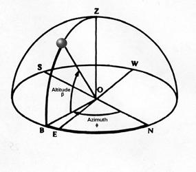
Figure 7. Solar Position Illustration
The Solar Altitude Angle (b) is the angle of the sun above the horizontal (degrees).
The Solar Hour Angle (H) gives the apparent solar time for the current time period (degrees). It is common astronomical practice to express the hour angle in hours, minutes and seconds of time rather than in degrees. You can convert the hour angle displayed from EnergyPlus to time by dividing by 15. (Note that 1 hour is equivalent to 15 degrees; 360° of the Earth’s rotation takes place every 24 hours.) The relationship of angles in degrees to time is shown in the following table:
Table 6. Relationship of Angles (degrees) to Time
|
Unit of Angle |
Equivalent time |
|
1 radian |
3.819719 hours |
|
1 degree |
4 minutes |
|
1 arcmin |
4 seconds |
|
1 arcsec |
0.066667 seconds |
This field shows whether or not (1=yes, 0=no) the weather shows “raining”. For a Design Day, one can denote rain for the entire day but not timestep by timestep. Weather files may indicate rain for a single time interval. This is an “averaged” field – thus a 1 shown for a time period (e.g. daily reporting) means that it was raining during each timestep of that period.
This field shows whether or not (1=yes, 0=no) the weather shows “snow on the ground”. For a Design Day, one can denote snow for the entire day but not timestep by timestep. Weather files may indicate snow (snow depth) for a single time interval. This is an “averaged” field – thus a 1 shown for a time period (e.g. daily reporting) means that there was snow on the ground during each timestep of that period.
This field shows when daylight saving time (1=yes, 0=no) is in effect. Though shown as an average variable, this value is only set on a daily basis.
This field shows what “day type” the current day is. Daytypes are (1=Sunday, 2=Monday, etc.) with Holiday=8, SummerDesignDay=9, WinterDesignDay=10, CustomDay1=11, CustomDay2=12. Though shown as an average variable, this value is only set on a daily basis.
The value of the Water Mains Temperature is reported in C following the calculation shown in the Water Mains Temperature object.
The rate and quantity of precipitation at the site. These outputs are only available if a Site Precipication object is used. Precipitation is measured in meters.
This is the scheduled amount of irrigation for the green roof (ecoroof) based on the user input. Amount is measured in meters.
This is the actual amount of irrigation for the green roof (ecoroof) based on the scheduled user input and moisture state/saturation of the soil. Amount is measured in meters.
Local atmospheric properties for outdoor air temperature and wind speed are separately calculated and reported for all zones, surfaces, and outdoor air nodes. The report variables are associated with their respective objects:
Zone,Average,Zone Outdoor Dry Bulb [C]
Zone,Average,Zone Outdoor Wet Bulb [C]
Zone,Average,Zone Outdoor Wind Speed [m/s]
Zone,Average,Surface Ext Outdoor Dry Bulb [C]
Zone,Average,Surface Ext Outdoor Wet Bulb [C]
Zone,Average,Surface Ext Wind Speed [m/s]
HVAC,Average,System Node Temp[C] (for OUTDOOR AIR NODE object)
The outdoor air dry-bulb temperature calculated at the height above ground of the zone centroid.
The outdoor air wet-bulb temperature calculated at the height above ground of the zone centroid.
The outdoor wind speed calculated at the height above ground of the zone centroid.
The outdoor air dry-bulb temperature calculated at the height above ground of the surface centroid.
The outdoor air wet-bulb temperature calculated at the height above ground of the surface centroid.
The outdoor wind speed calculated at the height above ground of the surface centroid.
When reporting for the OutdoorAir:Node object, this is the outdoor air dry-bulb temperature calculated at the height above ground of the node, if height is specified in the input.
This group of objects allows the user to influence scheduling of many items (such as occupancy density, lighting, thermostatic controls, occupancy activity). In addition, schedules are used to control shading element density on the building.
EnergyPlus schedules consist of three pieces: a day description, a week description, and an annual description. An optional element is the schedule type. Each description level builds off the previous sub-level. The day description is simply a name and the values that span the 24 hours in a day to be associated with that name. The week description also has an identifier (name) and twelve additional names corresponding to previously defined day descriptions. There are names for each individual day of the week plus holiday, summer design day, winter design day and two more custom day designations. Finally, the annual schedule contains an identifier and the names and FROM-THROUGH dates of the week schedules associate with this annual schedule. The annual schedule can have several FROM-THROUGH date pairs. One type of schedule reads the values from an external file to facilitate the incorporation of monitored data or factors that change throughout the year.
Schedules are processed by the EnergyPlus Schedule Manager, stored within the Schedule Manager and are accessed through module routines to get the basic values (timestep, hourly, etc). Values are resolved at the Zone Timestep frequency and carry through any HVAC timesteps.
A brief description of “Day Type” which is used in the SizingPeriod objects, RunPeriodControl:SpecialDays object, the Sizing objects and also used by reference in the Schedule:Week:Daily object (discussed later in this section).
Schedules work on days of the week as well as certain specially designated days. Days of the week are the normal – Sunday, Monday, Tuesday, Wednesday, Thursday, Friday and Saturday. Special day types that can be designated are: Holiday, SummerDesignDay, WinterDesignDay, CustomDay1, CustomDay2. These day types can be used at the user’s convenience to designate special scheduling (e.g. lights, electric equipment, set point temperatures) using these days as reference.
For example, a normal office building may have normal “occupancy” rules during the weekdays but significantly different use on weekend. For this, you would set up rules/schedules based on the weekdays (Monday through Friday, in the US) and different rules/schedules for the weekend (Saturday and Sunday, in the US). However, you could also specially designate SummerDesignDay and WinterDesignDay schedules for sizing calculations. These schedules can be activated by setting the Day Type field in the Design Day object to the appropriate season (SummerDesignDay for cooling design calculations; WinterDesignDay for heating design calculations).
In a different building, such as a theater/playhouse, the building may only have occupancy during certain weeks of the year and/or certain hours of certain days. If it was every week, you could designate the appropriate values during the “regular” days (Sunday through Saturday). But this would also be an ideal application for the “CustomDay1” and/or “CustomDay2”. Here you would set the significant occupancy, lighting, and other schedules for the custom days and use unoccupied values for the normal weekdays. Then, using a weather file and setting special day periods as appropriate, you will get the “picture” of the building usage during the appropriate periods.
Schedule types can be used to validate portions of the other schedules. Hourly day schedules, for example, are validated by range -- minimum/maximum (if entered) -- as well as numeric type (continuous or discrete). Annual schedules, on the other hand, are only validated for range – as the numeric type validation has already been done.
This alpha field should contain a unique (within the schedule types) designator. It is referenced wherever Schedule Type Limits Names can be referenced.
In this field, the lower (minimum) limit value for the schedule type should be entered. If this field is left blank, then the schedule type is not limited to a minimum/maximum value range.
In this field, the upper (maximum) limit value for the schedule type should be entered. If this field is left blank, then the schedule type is not limited to a minimum/maximum value range.
This field designates how the range values are validated. Using Continuous in this field allows for all numbers, including fractional amounts, within the range to be valid. Using Discrete in this field allows only integer values between the minimum and maximum range values to be valid.
This field is used to indicate the kind of units that may be associated with the schedule that references the ScheduleTypeLimits object. It is used by IDF Editor to display the appropriate SI and IP units. This field is not used by EnergyPlus. The available options are shown below. If none of these options are appropriate, select Dimensionless.
n Dimensionless
n Temperature
n DeltaTemperature
n PrecipitationRate
n Angle
n Convection Coefficient
n Activity Level
n Velocity
n Capacity
n Power
n Availability
n Percent
n Control
n Mode
Several IDF Examples will illustrate the use:
ScheduleTypeLimits,Any Number; ! Not limited
ScheduleTypeLimits,Fraction, 0.0 , 1.0 ,CONTINUOUS;
ScheduleTypeLimits,Temperature,-60,200,CONTINUOUS;
ScheduleTypeLimits,Control Type,0,4,DISCRETE;
ScheduleTypeLimits,On/Off,0,1,DISCRETE;
The day schedules perform the assignment of pieces of information across a 24 hour day. This can occur in various fashions including a 1-per hour assignment, a user specified interval scheme or a list of values that represent an hour or portion of an hour.
The Schedule:Day:Hourly contains an hour-by-hour profile for a single simulation day.
This field should contain a unique (within all DaySchedules) designation for this schedule. It is referenced by WeekSchedules to define the appropriate schedule values.
This field contains a reference to the Schedule Type Limits object. If found in a list of Schedule Type Limits (see above), then the restrictions from the referenced object will be used to validate the hourly field values (below).
These fields contain the hourly values for each of the 24 hours in a day. (Hour field 1 represents clock time 00:00:01 AM to 1:00:00 AM, hour field 2 is 1:00:01 AM to 2:00:00 AM, etc.) The values in these fields will be passed to the simulation as indicated for “scheduled” items.
An IDF example:
Schedule:Day:Hourly, Day On Peak, Fraction,
0.,0.,0.,0.,0.,0.,0.,0.,0.,1.,1.,1.,1.,1.,1.,1.,1.,1.,0.,0.,0.,0.,0.,0.;
The Schedule:Day:Interval introduces a slightly different way of entering the schedule values for a day. Using the intervals, you can shorten the “hourly” input of the “Schedule:Day:Hourly” object to 2 fields. And, more importantly, you can enter an interval that represents only a portion of an hour. Schedule values are “given” to the simulation at the zone timestep, so there is also a possibility of “interpolation” from the entries used in this object to the value used in the simulation.
This field should contain a unique (within all DaySchedules) designation for this schedule. It is referenced by WeekSchedules to define the appropriate schedule values.
This field contains a reference to the Schedule Type Limits object. If found in a list of Schedule Type Limits (see above), then the restrictions from the referenced object will be used to validate the hourly field values (below).
The value contained in this field directs how to apply values that aren’t coincident with the given timestep (ref: Timestep) intervals. If “Yes” is entered, then any intervals entered here will be interpolated/averaged and that value will be used at the appropriate minute in the hour. If “No” is entered, then the value that occurs on the appropriate minute in the hour will be used as the schedule value.
For example, if “yes” is entered and the interval is every 15 minutes (say a value of 0 for the first 15 minutes, then .5 for the second 15 minutes) AND there is a 10 minute timestep for the simulation: the value at 10 minutes will be 0 and the value at 20 minutes will be .25. For the same input entries but “no” for this field, the value at 10 minutes will be 0 and the value at 20 minutes will be .5.
To specify each interval, both an “until” time (which includes the designated time) and the value must be given.
The value of each field should represent clock time (standard) in the format “Until: HH:MM”. 24 hour clock format (i.e. 1PM is 13:00) is used. Note that Until: 7:00 includes all times up through 07:00 or 7am.
This represents the actual value to be passed to the simulation at the appropriate timestep. (Using interpolation value as shown above). Limits on the values are indicated by the Schedule Type Limits Name field of this object.
And an example of use:
Schedule:Day:Interval,
dd winter rel humidity, !- Name
Percent, !- Schedule Type Limits Name
No, !- Interpolate to Timestep
until: 24:00, !- Time 1
74; !- Value Until Time 1
To facilitate possible matches to externally generated data intervals, this object has been included. In similar fashion to the Schedule:Day:Interval object, this object can also include “sub-hourly” values but must represent a complete day in its list of values.
This field should contain a unique (within all day schedules) designation for this schedule. It is referenced by week schedules to define the appropriate schedule values.
This field contains a reference to the Schedule Type Limits object. If found in a list of Schedule Type Limits (see above), then the restrictions from the referenced object will be used to validate the hourly field values (below).
The value contained in this field directs how to apply values that aren’t coincident with the given timestep (ref: Timestep) intervals. If “Yes” is entered, then any intervals entered here will be interpolated/averaged and that value will be used at the appropriate minute in the hour. If “No” is entered, then the value that occurs on the appropriate minute in the hour will be used as the schedule value.
For example, if “yes” is entered and the minutes per item is 15 minutes (say a value of 0 for the first 15 minutes, then .5 for the second 15 minutes) AND there is a 10 minute timestep for the simulation: the value at 10 minutes will be 0 and the value at 20 minutes will be .25. For the same input entries but “no” for this field, the value at 10 minutes will be 0 and the value at 20 minutes will be .5.
This field allows the “list” interval to be specified in the number of minutes for each item. The value here must be <= 60 and evenly divisible into 60 (same as the timestep limits).
This is the value to be used for the specified number of minutes.
For example:
Schedule:Day:List,
Myschedule, ! name
Fraction, ! Schedule type
No, ! Interpolate value
30, ! Minutes per item
0.0, ! from 00:01 to 00:30
0.5, ! from 00:31 to 01:00
<etc>
The week schedule object(s) perform the task of assigning the day schedule to day types in the simulation. The basic week schedule is shown next.
This field should contain a unique (within all WeekSchedules) designation for this schedule. It is referenced by Schedules to define the appropriate schedule values.
These fields contain day schedule names for the appropriate day types. Days of the week (or special days as described earlier) will then use the indicated hourly profile as the actual schedule value.
An IDF example:
Schedule:Week:Daily, Week on Peak,
Day On Peak,Day On Peak,Day On Peak,
Day On Peak,Day On Peak,Day On Peak,
Day On Peak,Day On Peak,Day On Peak,
Day On Peak,Day On Peak,Day On Peak;
Further flexibility can be realized by using the Schedule:Week:Compact object. In this the fields, after the name is given, a “for” field is given for the days to be assigned and then a dayschedule name is used.
This field should contain a unique (within all WeekSchedules) designation for this schedule. It is referenced by Schedules to define the appropriate schedule values.
Each assignment is made in a pair-wise fashion. First the “days” assignment and then the dayschedule name to be assigned. The entire set of day types must be assigned or an error will result.
This field can optionally contain the prefix “For” for clarity. Multiple choices may then be combined on the line. Choices are: Weekdays, Weekends, Holidays, Alldays, SummerDesignDay, WinterDesignDay, Sunday, Monday, Tuesday, Wednesday, Thursday, Friday, Saturday, CustomDay1, CustomDay2. In fields after the first “for”, AllOtherDays may also be used.
This field contains the name of the day schedule (any of the Schedule:Day object names) that is to be applied for the days referenced in the prior field.
Some IDF examples:
Schedule:Week:Compact, Week on Peak,
For AllDays,
Day On Peak;
Schedule:Week:Compact, WeekDays on Peak,
WeekDays,
Day On Peak,
AllOtherDays
Day Off Peak;
The yearly schedule is used to cover the entire year using references to week schedules (which in turn reference day schedules). If the entered schedule does not cover the entire year, a fatal error will result.
This field should contain a unique (between Schedule:Year, Schedule:Compact, and Schedule:File) designation for the schedule. It is referenced by various “scheduled” items (e.g. Lights, People, Infiltration) to define the appropriate schedule values.
This field contains a reference to the Schedule Type Limits object. If found in a list of Schedule Type Limits (see above), then the restrictions from the referenced object will be used to validate the hourly field values (below).
Each of the designated fields is used to fully define the schedule values for the indicated time period). Up to 53 sets can be used. An error will be noted and EnergyPlus will be terminated if an incomplete set is entered. Missing time periods will also be noted as warning errors; for these time periods a zero (0.0) value will be returned when a schedule value is requested. Each of the sets has the following 5 fields:
This field contains the appropriate WeekSchedule name for the designated time period.
This numeric field is the starting month for the schedule time period.
This numeric field is the starting day for the schedule time period.
This numeric field is the ending month for the schedule time period.
This numeric field is the ending day for the schedule time period.
Note that there are many possible periods to be described. An IDF example with a single period:
Schedule:Year, On Peak, Fraction,
Week On Peak, 1,1, 12,31;
And a multiple period illustration:
Schedule:Year,CoolingCoilAvailSched,Fraction,
FanAndCoilAllOffWeekSched, 1,1, 3,31,
FanAndCoilSummerWeekSched, 4,1, 9,30,
FanAndCoilAllOffWeekSched, 10,1, 12,31;
The following definition will generate an error (if any scheduled items are used in the simulation):
Schedule:Year,MySchedule,Fraction,4,1,9,30;
For flexibility, a schedule can be entered in “one fell swoop”. Using the Schedule:Compact object, all the features of the schedule components are accessed in a single command. Like the “regular” schedule object, each schedule:compact entry must cover all the days for a year. Additionally, the validations for DaySchedule (i.e. must have values for all 24 hours) and WeekSchedule (i.e. must have values for all day types) will apply. Schedule values are “given” to the simulation at the zone timestep, so there is also a possibility of “interpolation” from the entries used in this object to the value used in the simulation.
This object is an unusual object for description. For the data the number of fields and position are not set, they cannot really be described in the usual Field # manner. Thus, the following description will list the fields and order in which they must be used in the object. The name and schedule type are the exceptions:
This field should contain a unique (between Schedule:Year, Schedule:Compact, and Schedule:File) designation for the schedule. It is referenced by various “scheduled” items (e.g. Lights, People, Infiltration) to define the appropriate schedule values.
This field contains a reference to the Schedule Type Limits object. If found in a list of Schedule Type Limits (see above), then the restrictions from the referenced object will be used to validate the hourly field values (below).
Each compact schedule must contain the elements Through (date), For (days), Interpolate (optional), Until (time of day) and Value. In general, each of the “titled” fields must include the “title”.
This field starts with “Through:” and contains the ending date for the schedule period (may be more than one). Refer to Table 3. Date Field Interpretation for information on date entry – note that only Month-Day combinations are allowed for this field. Each “through” field generates a new WeekSchedule named “Schedule Name”_wk_# where # is the sequential number for this compact schedule.
This field starts with “For:” and contains the applicable days (reference the compact week schedule object above for complete description) for the 24 hour period that must be described. Each “for” field generates a new DaySchedule named “Schedule Name”_dy_# where # is the sequential number for this compact schedule.
This field, if used, starts with “Interpolate:” and contains the word “Yes” or “No”. If this field is not used, it should not be blank – rather just have the following field appear in this slot. The definition of “Interpolate” in this context is shown in the interval day schedule above.
This field contains the ending time (again, reference the interval day schedule discussion above) for the current days and day schedule being defined.
Finally, the value field is the schedule value for the specified time interval.
And, some IDF examples:
Schedule:Compact,
POFF, !- Name
Fraction, !- Schedule Type Limits Name
Through: 4/30,
For: AllDays,
Until: 24:00, 1.0,
Through: 12/31,
For: Weekdays,
Until: 7:00, .1,
Until: 17:00, 1.0,
Until: 24:00, .1,
For: Weekends Holidays,
Until: 24:00, .1,
For: AllOtherDays,
Until: 24:00, .1;
! Schedule Continuous
Schedule:Compact,
Continuous,
on/off,
Through: 12/31,
For: AllDays,
Until: 24:00, 1.0;
! Schedule Daytime Ventilation
Schedule:Compact,
Daytime Ventilation,
Fraction,
Through: 12/31,
For: Weekdays SummerDesignDay,
Until: 08:00, 0.0,
Until: 18:00, 1.0,
Until: 24:00, 0.0,
For: Weekends WinterDesignDay,
Until: 10:00, 0.0,
Until: 16:00, 1.0,
Until: 24:00, 0.0,
For: Holidays AllOtherDays,
Until: 24:00, 0.0;
The constant schedule is used to assign a constant hourly value. This schedule is created when a fixed hourly value is desired to represent a period of interest (e.g., always on operation mode for supply air fan).
This field should contain a unique name designation for this schedule. It is referenced by Schedules to define the appropriate schedule value.
This field contains a reference to the Schedule Type Limits object. If found in a list of Schedule Type Limits (see above), then the restrictions from the referenced object will be used to validate the hourly field values (below).
This field contains a constant real value. A fixed value is assigned as an hourly value.
An IDF example:
Schedule:Constant,
AlwaysOn, !- Name
On/Off, !- Schedule Type Limits Name
1.0; !- Hourly Value
ScheduleTypeLimits,
On/Off, !- Name
0, !- Lower Limit Value
1, !- Upper Limit Value
DISCRETE, !- Numeric Type
Availability; !- Unit Type
At times, data is available from a building being monitored or for factors that change throughout the year. The Schedule:File object allows this type of data to be used in EnergyPlus as a schedule. Schedule:File can also be used to read in hourly schedules computed by other software or developed in a spreadsheet or other utility.
The format for the data file referenced is a text file with values separated by commas (or other optional delimiters) with one line per hour. The file may contain header lines that are skipped. The file should contain values for an entire year (8760 or 8784 lines of data) or a warning message will be issued. Multiple schedules may be created using a single external data file or multiple external data files may be used. The first row of data must be for January 1, hour 1.
Schedule:File may be used along with the FuelFactors object and TDV files in the DataSets directory to compute Time Dependent Valuation based source energy as used by the California Energy Commission’s Title 24 Energy Code. See Fuel Factor for more discussion on Time Dependent Valuation.
This field should contain a unique (between Schedule:Year, Schedule:Compact, and Schedule:File) designation for the schedule. It is referenced by various “scheduled” items (e.g. Lights, People, Infiltration, FuelFactors) to define the appropriate schedule values.
This field contains a reference to the Schedule Type Limits object. If found in a list of Schedule Type Limits (see above), then the restrictions from the referenced object will be used to validate the hourly field values (below).
This field contains the name of the file that contains the data for the schedule. The field should include a full path with file name. The field must be <= 100 characters. The file name must not include commas or an exclamation point. A relative path or a simple file name will not work with version 6.0 or later when using EP-Launch due to the use of temporary directories as part of the execution of EnergyPlus. If using RunEPlus.bat to run EnergyPlus from the command line, a relative path or a simple file name may work if RunEPlus.bat is run from the folder that contains EnergyPlus.exe.
The column that contains the value to be used in the schedule. The first column is column one. If no data for a row appears for a referenced column the value of zero is used for the schedule value for that hour.
Many times the data in a file contains rows (lines) that are describing the files or contain the names of each column. These rows need to be skipped and the number of skipped rows should be entered for this field. The next row after the skipped rows must contain data for January 1, hour 1.
The value entered in this field should be either 8760 or 8784 as the number of hours of data. 8760 does not include the extra 24 hours for a leap year (if needed). 8784 will include the possibility of leap year data which can be processed according to leap year indicators in the weather file or specified elsewhere. Note if the simulation does not have a leap year specified but the schedule file contains 8784 rows of data, the first 8760 rows of data will be used. The schedule manager will not know to skip the 24 rows representing Feburary 29.
This field specifies the character used to separate columns of data if the file has more than one column. The choices are: Comma, Tab, Fixed (spaces fill each column to a fixed width), or Semicolon. The default is Comma.
Here is an IDF example:
Schedule:File,
elecTDVfromCZ01res, !- Name
Any Number, !- ScheduleType
TDV_kBtu_CTZ01.csv, !- Name of File
2, !- Column Number
4, !- Rows to Skip at Top
8760, !- Number of Hours of Data
Comma; !- Column Separator
or with a relational path:
Schedule:File,
elecTDVfromCZ01res, !- Name
Any Number, !- ScheduleType
DataSets\TDV\TDV_kBtu_CTZ01.csv, !- Name of File
2, !- Column Number
4; !- Rows to Skip at Top
An optional report can be used to gain the values described in the previous Schedule objects. This is a condensed reporting that illustrates the full range of schedule values – in the style of input: DaySchedule, WeekSchedule, Annual Schedule.
! will give them on hourly increments (day schedule resolution)
Output:Reports, Schedules, Hourly;
! will give them at the timestep of the simulation
Output:Reports, Schedules, Timestep;
This report is placed on the eplusout.eio file. Details of this reporting are shown in the Output Details and Examples document.
Zone,Average,Schedule Value []
This is the schedule value (as given to whatever entity that uses it). It has no units in this context because values may be many different units (i.e. temperatures, fractions, watts). For best results, you may want to apply the schedule name when you use this report variable to avoid output proliferation. For example, the following reporting should yield the values shown above, depending on day of week and day type:
Output:Variable,People_Shopping_Sch,Schedule Value,hourly;
Output:Variable,Activity_Shopping_Sch,Schedule Value,hourly;
This group of objects describes the physical properties and configuration for the building envelope and interior elements. That is, the walls, roofs, floors, windows, doors for the building.
Building element constructions in EnergyPlus are built from the basic thermal and other material property parameters in physical constructions. Materials are specified by types and named. Constructions are defined by the composition of materials. Finally, surfaces are specified for the building with geometric coordinates as well as referenced constructions.
There are several material “types” which may be used to describe layers within opaque construction elements. The choice of which of these types to use is left up to the user. However, some guidance as to which material type to use is appropriate before describing each in detail. The opaque types are:
n Material
n Material:NoMass
n Material:AirGap
n Material:RoofVegetation
n Material:InfraredTransparent
Material is the “preferred” type of material. This requires knowledge of many of the thermal properties of the material, but it allows EnergyPlus to take into account the thermal mass of the material and thus allows the evaluation of transient conduction effects. Material:NoMass is similar in nature but only requires the thermal resistance (R-value) rather than the thickness, thermal conductivity, density, and specific heat. Note that using a simple R-value only material forces EnergyPlus to assume steady state heat conduction through this material layer. Finally, Material:AirGap should only be used for an air gap between other layers in a construction. This type assumes that air is sufficiently lightweight to require only an R-value. In addition, since it is not exposed to any external environment, surface properties such as absorptance are not necessary. Material:RoofVegetation is used to help model “green roofs”. Material:InfraredTransparent is used similarly to the NoMass materials. Each of these materials is described in more detail below.
There are several material additions that can be made to the basic material properties. These additional material types are:
n MaterialProperty:MoisturePenetrationDepth:Settings
n MaterialProperty:HeatAndMoistureTransfer:SorptionIsotherm
n MaterialProperty:HeatAndMoistureTransfer:Diffusion
n MaterialProperty:HeatAndMoistureTransfer:Settings
n MaterialProperty:HeatAndMoistureTransfer:Redistribution
n MaterialProperty:HeatAndMoistureTransfer:Suction
n MaterialProperty:HeatAndMoistureTransfer:ThermalConductivity
n MaterialProperty:PhaseChange
These material property objects are used in conjunction with the basic material specification and reference back to the name of the basic material type. Without the basic material type specified the program, will give a severe error and terminate. For example, specifying the moisture materials and changing the HeatBalanceAlgorithm to a moisture simulation will allow the moisture simulation to take place.
This definition should be used when the four main thermal properties (thickness, conductivity, density, and specific heat) of the material are known. This syntax is used to describe opaque construction elements only.
This field is a unique reference name that the user assigns to a particular material. This name can then be referred to by other input data (ref: Construction).
This alpha field defines the relative roughness of a particular material layer. This parameter only influences the convection coefficients, more specifically the exterior convection coefficient. A special keyword is expected in this field with the options being “VeryRough”, “Rough”, “MediumRough”, “MediumSmooth”, “Smooth”, and “VerySmooth” in order of roughest to smoothest options.
This field characterizes the thickness of the material layer in meters. This should be the dimension of the layer in the direction perpendicular to the main path of heat conduction. This value must be a positive.
This field is used to enter the thermal conductivity of the material layer. Units for this parameter are W/(m-K). Thermal conductivity must be greater than zero.
This field is used to enter the density of the material layer in units of kg/m3. Density must be a positive quantity.
This field represents the specific heat of the material layer in units of J/(kg-K). Note that these units are most likely different than those reported in textbooks and references which tend to use kJ/(kg-K) or J/(g-K). They were chosen for internal consistency within EnergyPlus. Only positive values of specific heat are allowed.
The thermal absorptance field in the Material input syntax represents the fraction of incident long wavelength radiation that is absorbed by the material. This parameter is used when calculating the long wavelength radiant exchange between various surfaces and affects the surface heat balances (both inside and outside as appropriate). For long wavelength radiant exchange, thermal emissivity and thermal emittance are equal to thermal absorptance. Values for this field must be between 0.0 and 1.0 (with 1.0 representing “black body” conditions).
The solar absorptance field in the Material input syntax represents the fraction of incident solar radiation that is absorbed by the material. Solar radiation includes the visible spectrum as well as infrared and ultraviolet wavelengths. This parameter is used when calculating the amount of incident solar radiation absorbed by various surfaces and affects the surface heat balances (both inside and outside as appropriate). If solar reflectance (or reflectivity) data is available, then absorptance is equal to 1.0 minus reflectance (for opaque materials). Values for this field must be between 0.0 and 1.0.
The visible absorptance field in the Material input syntax represents the fraction of incident visible wavelength radiation that is absorbed by the material. Visible wavelength radiation is slightly different than solar radiation in that the visible band of wavelengths is much more narrow while solar radiation includes the visible spectrum as well as infrared and ultraviolet wavelengths. This parameter is used when calculating the amount of incident visible radiation absorbed by various surfaces and affects the surface heat balances (both inside and outside as appropriate) as well as the daylighting calculations. If visible reflectance (or reflectivity) data is available, then absorptance is equal to 1.0 minus reflectance (for opaque materials). Values for this field must be between 0.0 and 1.0.
An IDF example:
Material,A2 - 4 IN DENSE FACE BRICK, ! Material Name
Rough, ! Roughness
0.1014984 , ! Thickness {m}
1.245296 , ! Conductivity {W/M*K}
2082.400 , ! Density {Kg/M**3}
920.4800 , ! Specific Heat {J/Kg*K}
0.9000000 , ! Thermal Absorptance
0.9300000 , ! Solar Absorptance
0.9300000 ; ! Visible Absorptance
Use this definition when only the thermal resistance (R value) of the material is known. This object is used to describe opaque construction elements.
This field is a unique reference name that the user assigns to a particular material. This name can then be referred to by other input data (ref: Construction, SurfaceControl:MoveableInsulation).
This alpha field defines the relative roughness of a particular material layer. This parameter only influences the convection coefficients, more specifically the exterior convection coefficient. A keyword is expected in this field with the options being “VeryRough”, “Rough”, “MediumRough”, “MediumSmooth”, “Smooth”, and “VerySmooth” in order of roughest to smoothest options.
This field is used to enter the thermal resistance (R-value) of the material layer. Units for this parameter are (m2-K)/W. Thermal resistance must be greater than zero. Note that most R-values in the USA are calculated in Inch-Pound units and must be converted to the SI equivalent.
The thermal absorptance field in the Material input syntax represents the fraction of incident long wavelength radiation that is absorbed by the material. This parameter is used when calculating the long wavelength radiant exchange between various surfaces and affects the surface heat balances (both inside and outside as appropriate). For long wavelength radiant exchange, thermal emissivity and thermal emittance are equal to thermal absorptance. Values for this field must be between 0.0 and 1.0 (with 1.0 representing “black body” conditions).
The solar absorptance field in the Material input syntax represents the fraction of incident solar radiation that is absorbed by the material. Solar radiation includes the visible spectrum as well as infrared and ultraviolet wavelengths. This parameter is used when calculating the amount of incident solar radiation absorbed by various surfaces and affects the surface heat balances (both inside and outside as appropriate). If solar reflectance (or reflectivity) data is available, then absorptance is equal to 1.0 minus reflectance (for opaque materials). Values for this field must be between 0.0 and 1.0.
The visible absorptance field in the Material input syntax represents the fraction of incident visible wavelength radiation that is absorbed by the material. Visible wavelength radiation is slightly different than solar radiation in that the visible band of wavelengths is much more narrow while solar radiation includes the visible spectrum as well as infrared and ultraviolet wavelengths. This parameter is used when calculating the amount of incident visible radiation absorbed by various surfaces and affects the surface heat balances (both inside and outside as appropriate) as well as the daylighting calculations. If visible reflectance (or reflectivity) data is available, then absorptance is equal to 1.0 minus reflectance (for opaque materials). Values for this field must be between 0.0 and 1.0.
An IDF example:
Material:NoMass,R13LAYER, ! Material Name
Rough, ! Roughness
2.290965 , ! Resistance {M**2K/W}
0.9000000 , ! Thermal Absorptance
0.7500000 , ! Solar Absorptance
0.7500000 ; ! Visible Absorptance
A Infrared Transparent surface is similar to a resistance-only surface. The idd object for this type of surface is shown below. The surface will actually participate in the transfer of visible and solar radiation by doing a wavelength transformation and making all short wave length radiation that is incident on the surface into long wave length radiation and having it participate in the long wavelength radiant exchange. Note the ConvectionCoefficient instructions that follow the Infrared Transparent construction object below.
This field contains the unique name (across all Material objects) for the Infrared Transparent material.
A Infrared Transparent surface should not participate in a convective/conductive exchange between the zones it separates. In order to minimize this effect, the ConvectionCoefficients object must be used for the surfaces referencing the Infrared Transparent (IRT) construction.
An example idf object specification for use with the IRT surface is shown below. Note that surfaces are not described in this example
Material:InfraredTransparent,
IRTMaterial1; !- Name
Construction,
IRTSurface, !- Name
IRTMaterial1; !- Outside Layer
SurfaceProperty:ConvectionCoefficients,
Bottom:Top, !- SurfaceName
Outside, !- Convection Type 1
value, !- Convection Value Type 1
0.1, !- Convection value 1 {W/m2-K}
, !- Convection Schedule 1
Inside, !- Convection Type 2
value, !- Convection Value Type 2
0.1; !- Convection value 2 {W/m2-K}
SurfaceProperty:ConvectionCoefficients,
SecondLevel:Bottom, !- SurfaceName
Outside, !- Convection Type 1
value, !- Convection Value Type 1
0.1, !- Convection value 1 {W/m2-K}
, !- Convection Schedule 1
Inside, !- Convection Type 2
value, !- Convection Value Type 2
0.1; !- Convection value 2 {W/m2-K}
SurfaceProperty:ConvectionCoefficients,
SecondLevel:Top, !- SurfaceName
Outside, !- Convection Type 1
value, !- Convection Value Type 1
0.1, !- Convection value 1 {W/m2-K}
, !- Convection Schedule 1
Inside, !- Convection Type 2
value, !- Convection Value Type 2
0.1; !- Convection value 2 {W/m2-K}
SurfaceProperty:ConvectionCoefficients,
ThirdLevel:Bottom, !- SurfaceName
Outside, !- Convection Type 1
value, !- Convection Value Type 1
0.1, !- Convection value 1 {W/m2-K}
, !- Convection Schedule 1
Inside, !- Convection Type 2
value, !- Convection Value Type 2
0.1; !- Convection value 2 {W/m2-K}
This material is used to describe the air gap in an opaque construction element. Glass elements use a different property (WindowGas) to describe the air between two glass layers.
This field is a unique reference name that the user assigns to a particular material. This name can then be referred to by other input data (ref: Construction).
This field is used to enter the thermal resistance (R-value) of the material layer. Units for this parameter are (m2-K)/W. Thermal resistance must be greater than zero. Note that most R-values in the USA are calculated in Inch-Pound units and must be converted to the SI equivalent.
An IDF example:
Material:AirGap,B1 - AIRSPACE RESISTANCE, ! Material Name
0.1603675 ; ! Resistance {M**2K/W}
This material is used to describe the five moisture material properties that are used in the EMPD (Effective Moisture Penetration Depth) heat balance solution algorithm (known there as MoisturePenetrationDepthConductionTransferFunction). The EMPD algorithm is a simplified, lumped moisture model that simulates moisture storage and release from interior surfaces. The model uses "actual" convective mass transfer coefficients that are determined by existing heat and mass transfer relationships, e.g. the Lewis relation. An effective moisture penetration depth may be determined from either experimental or detailed simulation data by using actual surface areas and moisture sorption isotherms.
This moisture model will be used when the appropriate EMPD moisture materials are specified and the Solution Algorithm parameter is set to EMPD.
This field is a unique reference name that the user assigns to a particular material. This name can then be referred to by other input data (ref: Construction).
This field is used to enter the effective moisture penetration depth of the material layer. Units for this parameter are (m).
The next four fields, coefficients “a”, “b”, “c”, and “d”, help define the sorption isotherm curve used for building materials under equilibrium conditions. They are used to define the relationship between the material’s moisture content and the surface air relative humidity (ref: Effective Moisture Penetration Depth (EMPD) Model in the Engineering Reference):
![]()
where
a,b,c,d = Coefficients to define the relationship between the material’s moisture content and the surface air relative humidity
U = Moisture content defined as the mass fraction of water contained in a material [kg/kg]
![]() = Surface air relative humidity [0 to 1]
= Surface air relative humidity [0 to 1]
Ann IDF example showing how it is used in conjunction with Material in synchronous pairs:
Material,
E1 - 3 / 4 IN PLASTER OR GYP BOARD, !- Name
Smooth, !- Roughness
1.9050000E-02, !- Thickness {m}
0.7264224, !- Conductivity {W/m-K}
1601.846, !- Density {kg/m3}
836.8000, !- Specific Heat {J/kg-K}
0.9000000, !- Thermal Absorptance
0.9200000, !- Solar Absorptance
0.9200000; !- Visible Absorptance
MaterialProperty:MoisturePenetrationDepth:Settings,
E1 - 3 / 4 IN PLASTER OR GYP BOARD, !- Name
0.004, !- Effective Moisture Penetration Depth {m}
0.072549, !- Moisture Equation Coefficient a {dimensionless}
0.397173, !- Moisture Equation Coefficient b {dimensionless}
0.007774, !- Moisture Equation Coefficient c {dimensionless}
11.7057; !- Moisture Equation Coefficient d {dimensionless}
Material,
C10 - 8 IN HW CONCRETE, !- Name
MediumRough, !- Roughness
0.2033016, !- Thickness {m}
1.729577, !- Conductivity {W/m-K}
2242.585, !- Density {kg/m3}
836.8000, !- Specific Heat {J/kg-K}
0.9000000, !- Thermal Absorptance
0.6500000, !- Solar Absorptance
0.6500000; !- Visible Absorptance
MaterialProperty:MoisturePenetrationDepth:Settings,
C10 - 8 IN HW CONCRETE, !- Name
0.004, !- Effective Moisture Penetration Depth {m}
0.018062, !- Moisture Equation Coefficient a {dimensionless}
0.451879, !- Moisture Equation Coefficient b {dimensionless}
0.026178, !- Moisture Equation Coefficient c {dimensionless}
10.8356; !- Moisture Equation Coefficient d {dimensionless}
Output variables applicable to heat transfer surfaces using EMPD model:
Zone,Average,Inside Surface Vapor Density [kg/m3]
Zone,Average,Inside Surface Humidity Ratio []
Zone,Average,Inside Surface Relative Humidity [%]
The following variables apply only to surfaces, where the material assigned to the inside layers is MaterialProperty:MoisturePenetrationDepth:Settings. The EMPD (Effective Moisture Penetration Depth) moisture balance solution algorithm is used to calculate the inside surface moisture levels.
The vapor density at the inside surface, where the EMPD moisture balance solution algorithm is applied.
The humidity ratio at the inside surface, where the EMPD moisture balance solution algorithm is applied.
The relative humidity at the inside surface, where the EMPD moisture balance solution algorithm is applied.
Advanced/Research Usage: This material is used to describe the temperature dependent material properties that are used in the Conduction Finite Difference solution algorithm. This conduction model is done when the appropriate materials are specified and the Solution Algorithm parameter is set to ConductionFiniteDifference. This permits simulating temperature dependent thermal conductivity and phase change materials (PCM) in EnergyPlus.
This field is a regular material name specifying the material with which this additional temperature dependent property information will be associated.
This field is used to enter the temperature dependent coefficient for thermal conductivity of the material. Units for this parameter are (W/(m-K2). This is the thermal conductivity change per unit temperature excursion from 20 C. The conductivity value at 20 C is the one specified with the basic material properties of the regular material specified in the name field. The thermal conductivity is obtained from:
![]()
where:
ko is the 20C value of thermal conductivity(normal idf input)
k1 is the change in conductivity per degree temperature difference from 20C
(this field).
The temperature – enthalpy set of inputs specify a two column tabular temperature-enthalpy function for the basic material. Sixteen pairs can be specified. Specify only the number of pairs necessary. The tabular function must cover the entire temperature range that will be seen by the material in the simulation. It is suggested that the function start at a low temperature, and extend to 100C. Note that the function has no negative slopes and the lowest slope that will occur is the base material specific heat. Enthalpy contributions of the phase change are always added to the enthalpy that would result from a constant specific heat base material. An example of a simple enthalpy temperature function is shown below.
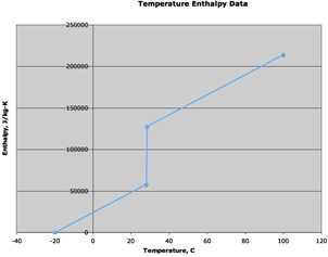
This field is used to specify the temperature of the temperature-enthalpy function for the basic material. Units are C.
This field specifies the enthalpy that corresponds to the previous temperature of the temperature-enthalpy function. Units are J/kg.
And, an IDF example showing how it is used in conjunction with the Material:
Note, the following Heat Balance Algorithm is necessary (only specified once). Also, when using ConductionFiniteDifference, it is more efficient to set the zone timestep shorter than those used for the ConductionTransferFunction solution algorithm. It should be set to 12 timesteps per hour or greater, and can range up to 60.
HeatBalanceAlgorithm,
ConductionFiniteDifference;
Timestep,
12;
Material,
E1 - 3 / 4 IN PLASTER OR GYP BOARD, !- Name
Smooth, !- Roughness
1.9050000E-02, !- Thickness {m}
0.7264224, !- Conductivity {W/m-K}
1601.846, !- Density {kg/m3}
836.8000, !- Specific Heat {J/kg-K}
0.9000000, !- Thermal Absorptance
0.9200000, !- Solar Absorptance
0.9200000; !- Visible Absorptance
MaterialProperty:PhaseChange,
E1 - 3 / 4 IN PLASTER OR GYP BOARD, !- Name
0.0, !- Temperature coefficient,thermal conductivity(W/m K2)
-20., !- Temperature 1, C
0.01, !- Enthalpy 1 at –20C, (J/kg)
20., !- Temperature 2, C
33400, !- Enthalpy 2, (J/kg)
20.5, !- temperature 3, C
70000, !- Ethalpy 3, (J/kg)
100., !- Temperature 4, C
137000; !- Enthalpy 4, (J/kg)
This object is used to describe the temperature dependent material properties that are used in the CondFD (Conduction Finite Difference) solution algorithm. This conduction model is used when the appropriate CondFD materials are specified and the Solution Algorithm parameter is set to condFD.
This field is a regular material name specifying the material with which this additional temperature dependent property information will be associated.
The temperature – conductivity set of inputs specify a two column tabular temperature-thermal conductivity function for the basic material. Ten pairs can be specified. Specify only the number of pairs necessary.
This field is used to specify the temperature of the temperature-conductivity function for the basic material. Units are C.
This field specifies the enthalpy that corresponds to the previous temperature of the temperature-enthalpy function. Units are W/m-K.
And, an IDF example showing how it is used in conjunction with the Materials:
Note, the following Heat Balance Algorithm is necessary (only specified once). Also, when using Conduction Finite Difference, it is more efficient to set the zone time step shorter than those used for the Conduction Transfer Function solution algorithm. It should be set to 12 time steps per hour or greater, and can range up to 60.
HeatBalanceAlgorithm,
ConductionFiniteDifference;
Timestep,
12;
Material,
PCMPlasterBoard , !- Name
Smooth, !- Roughness
1.9050000E-02, !- Thickness {m}
4.2, !- Conductivity {W/m-K}
1601.846, !- Density {kg/m3}
836.8000, !- Specific Heat {J/kg-K}
0.9000000, !- Thermal Absorptance
0.9200000, !- Solar Absorptance
0.9200000; !- Visible Absorptance
MaterialProperty:VariableThermalConductivity,
PCMPlasterBoard, !- Name
0, !- Temperature 1 {C}
4.2, !- Thermal Conductivity 1 {W/m-K}
22, !- Temperature 2 {C}
4.2, !- Thermal Conductivity 2 {W/m-K}
22.1, !- Temperature 3 {C}
2.5, !- Thermal Conductivity 3 {W/m-K}
100, !- Temperature 4 {C}
2.5; !- Thermal Conductivity 4 {W/m-K}
The Conduction Finite Difference and the Conduction Finite Difference Simplified solution algorithms both use a finite difference solution technique, the surfaces are divided into a nodal arrangement. (Simplfied algorithm uses only two nodes). In order to see detailed node infomation, three output variables are available. They provide the node temperatures, the inside heat flux and the outside heat flux.
The following output variables are applicable to all opaque heat transfer surfaces when using Solution Algorithms ConductionFiniteDifference or ConductionFiniteDifferenceSimplified:
Zone,Average,CondFD Outside Surface Heat Flux [W/m2]
Zone,Average,CondFD Inside Surface Heat Flux [W/m2]
Zone,Average,CondFD Nodal Temperature [C]
The heat flux at the outside face of the surface that is being simulated with ConductionFiniteDifference or ConductionFiniteDifferenceSimplified.
The heat flux at the inside face of the surface that is being simulated with ConductionFiniteDifference or ConductionFiniteDifferenceSimplified.
This will output temperatures for each node in the surfaces being simulated with ConductionFiniteDifference or ConductionFiniteDifferenceSimplified. The key values for this output variable are the surface name plus node number, e.g. “ZN001:WALL001 Node #1:CondFD Nodal Temperature[C].” The nodes are numbered from outside to inside of the surface.
Advanced/Research Usage. This object is used to describe two of the seven additional material properties needed for the CombinedHeatAndMoistureFiniteElement heat balance solution algorithm. The settings object is used when the solutions algorithm is set to CombinedHeatAndMoistureFiniteElement and the appropriate material properties are assigned to each material. This permits the simulation of the moisture dependant thermal properties of the material as well as the transfer of moisture through, into and out of the material into the zone or exterior.
In addition to the Porosity and Initial Water content properties described here, five additional properties, described by tabulated relationships between variables, are required. These properties are;
n MaterialProperty:HeatAndMoistureTransfer:SorptionIsotherm
n MaterialProperty:HeatAndMoistureTransfer:Suction
n MaterialProperty:HeatAndMoistureTransfer:Redistribution
n MaterialProperty:HeatAndMoistureTransfer:Diffusion
n MaterialProperty:HeatAndMoistureTransfer:ThermalConductivity
All materials in a construction are required to have all material properties defined for HAMT to work.
Within the MaterialProperty:HeatAndMoistureTransfer:Settings object the following fields are defined.
This field is a unique reference name that the user assigns to a particular material. This name can then be referred to by other input data.
The porosity of a material is the maximum fraction, by volume, of a material that can be taken up with water. The units are [m3/m3].
For this solution algorithm, the initial water content is assumed to be distributed evenly through the depth of the material. The units are [kg/kg].
Below is an example input for the porosity and initial water content of a material.
MaterialProperty:HeatAndMoistureTransfer:Settings,
Concrete, !- Name
0.76, !- Porosity
0.2; !- Initial (or typical) Water content
Advanced/Research Usage. This material property is used in conjunction with the CombinedHeatAndMoistureFiniteElement heat balance solution algorithm.
The Isotherm data relates the moisture, or water content [kg/m3] of a material with the relative humidity (RH). The water content is expected to increase as relative humidity increases, starting at zero content at 0.0relative humidity fraction and reaching a maximum, defined by the porosity, at 1.0 relative humidity fraction, which corresponds to 100% relatve humidity. Relative humidities are entered as fraction for this object ranging from 0.0 to 1.0. These two extremes (0.0 and 1.0) are automatically set by the HAMT solution. However, if they are entered they will be used as extra data points. Data should be provided with increasing RH and moisture content up to as high an RH as possible to provide a stable solution. One possible reason for the following error message may be that a material has a very rapid increase in water content for a small change in RH, which can happen if the last entered water content point is at a low RH and the material has a very high porosity.
** Warning ** HeatAndMoistureTransfer: Large Latent Heat for Surface ROOF
Another potential reason for this error being generated is the use of inappropriate values for Vapor Transfer Coefficients. See the SurfaceProperties:VaporCoefficients object in the Advanced Surface Concepts group.
This field is a unique reference name that the user assigns to a particular material. This name can then be referred to by other input data.
A maximum of 25 coordinates can be specified.
The relative humidity of the xth coordinate. The relative humidity is entered as fraction, not in percent.
The Moisture Content of the xth coordinate. The units are [kg/m3]
Below is an example input for a material isotherm
MaterialProperty:HeatAndMoistureTransfer:SorptionIsotherm,
Concrete, !- Name
10, !- Number of data Coordinates
0.2205, !- Relative Humidity fraction #1
22.31, !- Moisture content #1
0.202, !- Relative Humidity fraction #2
19.665, !- Moisture content #2
0.449, !- Relative Humidity fraction #3
40.02, !- Moisture content #3
0.454, !- Relative Humidity fraction #4
36.915, !- Moisture content #4
0.6506, !- Relative Humidity fraction #5
56.005, !- Moisture content #5
0.655, !- Relative Humidity fraction #6
52.325, !- Moisture content #6
0.824, !- Relative Humidity fraction #7
72.565, !- Moisture content #7
0.8725, !- Relative Humidity fraction #8
85.1, !- Moisture content #8
0.924, !- Relative Humidity fraction #9
91.08, !- Moisture content #9
0.964, !- Relative Humidity fraction #10
100.28; !- Moisture content #10
Advanced/Research Usage. This material property is used in conjunction with the CombinedHeatAndMoistureFiniteElement heat balance solution algorithm.
The suction data relates the liquid transport coefficient, under suction, to the water content of a material. A data point at zero water content is required. The liquid transport coefficient at the highest entered water content value is used for all liquid transport coefficient values above this water content. These coefficients are used by HAMT when the rain flag is set in the weather file.
This field is a unique reference name that the user assigns to a particular material. This name can then be referred to by other input data.
A maximum of 25 points can be specified.
The moisture content of the xth point. The units are [kg/m3].
The Liquid Transport Coefficient of the xth point. The units are [m2/s].
Below is an example input for a material liquid transport coefficient under suction.
MaterialProperty:HeatAndMoistureTransfer:Suction,
Concrete, !- Name
5, !- Number of Suction points
0, !- Moisture content 1
0, !- Liquid Transport Coefficient 1
72, !- Moisture content 2
0.0000000000741, !- Liquid Transport Coefficient 2
85, !- Moisture content 3
0.000000000253, !- Liquid Transport Coefficient 3
100, !- Moisture content 4
0.00000000101, !- Liquid Transport Coefficient 4
118, !- Moisture content 5
0.00000000128; !- Liquid Transport Coefficient 5
Advanced/Research Usage. This material property is used in conjunction with the CombinedHeatAndMoistureFiniteElement heat balance solution algorithm.
The redistribution data relates the liquid transport coefficient to the water content of a material under normal conditions. A data point at zero water content is required. The liquid transport coefficient at the highest entered water content value is used for all liquid transport coefficient values above this water content. These coefficients are used by the Heat and Moisture Transfer algorithm when the rain flag is NOT set in the weather file.
This field is a unique reference name that the user assigns to a particular material. This name can then be referred to by other input data.
A maximum of 25 points can be specified.
The moisture content of the xth point. The units are [kg/m3].
The Liquid Transport Coefficient of the xth point. The units are [m2/s].
Below is an example input for the object.
MaterialProperty:HeatAndMoistureTransfer:Redistribution,
Concrete, !- Name
5, !- Number of Redistribution points
0, !- Moisture content 1
0, !- Liquid Transport Coefficient 1
72, !- Moisture content 2
0.00000000000741, !- Liquid Transport Coefficient 2
85, !- Moisture content 3
0.0000000000253, !- Liquid Transport Coefficient 3
100, !- Moisture content 4
0.000000000101, !- Liquid Transport Coefficient 4
118, !- Moisture content 5
0.000000000128; !- Liquid Transport Coefficient 5
Advanced/Research Usage. This material property is used in conjunction with the CombinedHeatAndMoistureFiniteElement heat balance solution algorithm.
The MU data relates the vapor diffusion resistance factor (dimensionless) to the relative humidity as fraction(RH). A data point at zero RH is required. The vapor diffusion resistance factor at the highest entered relative humidity (RH) value is used for all vapor diffusion resistance factor values above this RH. The relative humidity maximum value in fraction is 1.0.
This field is a unique reference name that the user assigns to a particular material. This name can then be referred to by other input data.
A maximum of 25 pairs can be specified.
The moisture content of the xth pair. The relative humidity is entered as fraction, not in percent.
The Liquid Transport Coefficient of the xth pair.
Below are some examples of the values for materials.
MaterialProperty:HeatAndMoistureTransfer:Diffusion,
Plywood, !- Name
3, !- Number of data Points
0, !- Relative Humidity Fraction 1
700, !- Water Vapor Diffusion Resistance Factor 1
0.5, !- Relative Humidity Fraction 2
200, !- Water Vapor Diffusion Resistance Factor 2
1, !- Relative Humidity Fraction 3
20; !- Water Vapor Diffusion Resistance Factor 3
MaterialProperty:HeatAndMoistureTransfer:Diffusion,
Concrete, !- Name
1, !- Number of Mu Points
0, !- Relative Humidity Fraction 1
180; !- Water Vapor Diffusion Resistance Factor 1
Advanced/Research Usage. This material property is used in conjunction with the CombinedHeatAndMoistureFiniteElement heat balance solution algorithm.
The thermal data relates the thermal conductivity [W/m-K] of a material to the moisture or water content [kg/m3]. A data point at zero water content is required. The thermal conductivity at the highest entered water content value is used for all thermal conductivity values above this water content. If this object is not defined for a material then the algorithm will use a constant value entered in the Material object for all water contents.
This field is a unique reference name that the user assigns to a particular material. This name can then be referred to by other input data.
A maximum of 25 coordinates can be specified.
The moisture content of the xth coordinate. The units are [kg/m3]
The Thermal Conductivity of the xth coordinate. The units are [W/m-K]
Below is an example of values for a material.
MaterialProperty:HeatAndMoistureTransfer:ThermalConductivity
Concrete, !- Name
2, !- Number of Thermal Coordinates
0, !- Moisture content #1
1.6, !- Thermal Conductivity #1
180, !- Moisture content #2
2.602; !- Thermal Conductivity #2
Zone,Average,HAMT Surface Water Content [kg/kg]
Zone,Average,HAMT Surface Interior Temperature [C]
Zone,Average,HAMT Surface Interior Relative Humidity [%]
Zone,Average,HAMT Surface Interior Vapor Pressure [Pa]
Zone,Average,HAMT Surface Exterior Temperature [C]
Zone,Average,HAMT Surface Exterior Relative Humidity [%]
Zone,Average,Inside Surface Relative Humidity [%]
This output is the summed water content [kg/kg] of all cells in a surface expressed as a fraction of the mass of the water to the material mass.
This output is the temperature [C] on the internal “surface” of the surface.
This output is the relative humidity on the internal “surface” of the surface expressed as a percentage.
This output is the vapor pressure [Pa] on the internal “surface” of the surface.
This output is the temperature on the external “surface” of the surface.
This output is the relative humidity on the external “surface” of the surface.
Zone,Average,HAMT Profile Construction Cell y Temperature [C]
Zone,Average,HAMT Profile Construction Cell y Water Content [kg/kg]
Zone,Average,HAMT Profile Construction Cell y Relative Humidity [%]
Detailed profile data for the variables Temperature[C], Relative Humidity [%] and Water Content [kg/kg] within each surface can also be reported. To calculate the heat and moisture transfer through surfaces HAMT splits up surfaces into discrete cells. Each cell is composed of a single material and has a position within the surface. HAMT automatically assigns cells to construction objects so that there are more cells closer to boundaries between materials and also at the “surfaces” of the surface. It is not possible for users to define their own cells. Each surface is made from a particular construction. The construction-surface relationship is output by HAMT to the eplusout.eio file with the following format.
! <HAMT cells>, Surface Name, Construction Name, Cell Numbers
! <HAMT origins>, Surface Name, Construction Name, Cell origins (m)
The output also contains the HAMT cell origins and cell number for each construction – surface combination. The coordinate system origin is defined as the exterior surface of the construction. Users can select any one of the Temperature, Relative Humidity or Water Content variables for any cell to be reported, using the following naming scheme for the output variable.
HAMT Profile Construction Cell <Cell#> <Variable>
It is better to specify the “key” or Surface Name in this output.
So for example to output the temperature of the 10th cell in a surface, eg “East Wall” would require the following output variable.
Output:Variable,
East Wall, !- Key Value
HAMT Profile Construction Cell 10 Temperature, !- Variable Name
Hourly; !- Reporting Frequency
By selecting a whole range of these reports and using the information in the eplusout.eio file it is possible to build up a temperature profile of the surface.
All the materials for glass windows and doors have the prefix “WindowMaterial”. The following WindowMaterial descriptions (Glazing, Glazing:RefractionExtinctionMethod, Gas, GasMixture, Shade, Screen and Blind) apply to glass windows and doors. The property definitions described herein for Glazing, Gas and GasMixture are supported by the National Fenestration Rating Council as standard.
“Front side” is the side of the layer opposite the zone in which the window is defined. “Back side” is the side closest to the zone in which the window is defined. Therefore, for exterior windows, “front side” is the side closest to the outdoors. For interior windows, “front side” is the side closest to the zone adjacent to the zone in which the window is defined.
The solar radiation transmitted by the window layers enters the zone and is a component of the zone load. The solar radiation absorbed in each solid layer (glass, shade, screen or blind) participates in the window layer heat balance calculation. The visible transmittance and reflectance properties of the window are used in the daylighting calculation.
In the following, for exterior windows, “front side” is the side of the glass closest to the outside air and “back side” is the side closest to the zone the window is defined in. For interzone windows, “front side” is the side closest to the zone adjacent to the zone the window is defined in and “back side” is the side closest to the zone the window is defined in.
The name of the glass layer. It corresponds to a layer in a window construction.
If Optical Data Type = SpectralAverage, the values you enter for solar transmittance and reflectance are assumed to be averaged over the solar spectrum, and the values you enter for visible transmittance and reflectance are assumed to be averaged over the solar spectrum and weighted by the response of the human eye. There is an EnergyPlus Reference Data Set for WindowMaterial:Glazing that contains spectral average properties for many different types of glass.
If Optical Data Type = Spectral, then, in the following field, you must enter the name of a spectral data set defined with the WindowGlassSpectralData object. In this case, the values of solar and visible transmittance and reflectance in the fields below should be blank.
If Optical Data Type = Spectral, this is the name of a spectral data set defined with a WindowGlassSpectralData object.
The surface-to-surface thickness of the glass (m).
Transmittance at normal incidence averaged over the solar spectrum. Used only when Optical Data Type = SpectralAverage.
For uncoated glass, when alternative optical properties are available—such as thickness, solar index of refraction, and solar extinction coefficient—they can be converted to equivalent solar transmittance and reflectance values using the equations given in “Conversion from Alternative Specification of Glass Optical Properties.”)
Front-side reflectance at normal incidence averaged over the solar spectrum. Used only when Optical Data Type = SpectralAverage.
Back-side reflectance at normal incidence averaged over the solar spectrum. Used only when Optical Data Type = SpectralAverage.
Transmittance at normal incidence averaged over the solar spectrum and weighted by the response of the human eye. Used only when Optical Data Type = SpectralAverage.
For uncoated glass, when alternative optical properties are available—such as thickness, visible index of refraction, and visible extinction coefficient—they can be converted to equivalent visible transmittance and reflectance values using the equations given in “Conversion from Alternative Specification of Glass Optical Properties.”)
Front-side reflectance at normal incidence averaged over the solar spectrum and weighted by the response of the human eye. Used only when Optical Data Type = SpectralAverage.
Back-side reflectance at normal incidence averaged over the solar spectrum and weighted by the response of the human eye. Used only when Optical Data Type = SpectralAverage.
Long-wave transmittance at normal incidence.
Front-side long-wave emissivity.
Back-side long-wave emissivity.
Thermal conductivity (W/m-K).
This is a factor that corrects for the presence of dirt on the glass. The program multiplies the fields “Solar Transmittance at Normal Incidence” and “Visible Transmittance at Normal Incidence” by this factor if the material is used as the outer glass layer of an exterior window or glass door.[2] If the material is used as an inner glass layer (in double glazing, for example), the dirt correction factor is not applied because inner glass layers are assumed to be clean. Using a material with dirt correction factor < 1.0 in the construction for an interior window will result in an error message.
Representative values of the dirt correction factor are shown in Table 7.
Table 7. Dirt Correction Factors
|
Type of Location |
Angle of Glazing |
||
|
Vertical |
45O |
Horizontal |
|
|
Non-industrial |
0.9 |
0.8 |
0.7 |
|
Industrial |
0.7 |
0.6 |
0.5 |
|
Very Dirty |
0.6 |
0.5 |
0.4 |
From Appendix A, “Daylighting in Sports Halls, Report 2,” SportScotland, Nov. 2002
(www.sportscotland.org.uk)
The default value of the dirt correction factor is 1.0, which means the glass is clean.
It is assumed that dirt, if present, has no effect on the IR properties of the glass.
Takes values No (the default) and Yes. If No, the glass is transparent and beam solar radiation incident on the glass is transmitted as beam radiation with no diffuse component. If Yes, the glass is translucent and beam solar radiation incident on the glass is transmitted as hemispherically diffuse radiation with no beam component.[3] See Figure 8. Solar Diffusing = Yes should only be used on the innermost pane of glass in an exterior window; it does not apply to interior windows.
For both Solar Diffusing = No and Yes, beam is reflected as beam with no diffuse component (see Figure 8)
If, in the Building object, Solar Distribution = FullInteriorAndExterior, use of Solar Diffusing = Yes for glass in an exterior window will change the distribution of interior solar radiation from the window. The result is that beam solar radiation that would be transmitted by a transparent window and get absorbed by particular interior surfaces will be diffused by a translucent window and be spread over more interior surfaces. This can change the time dependence of heating and cooling loads in the zone.
In a zone with Daylighting:Detailed, translucent glazing---which is often used in skylights---will provide a more uniform daylight illuminance over the zone and will avoid patches of sunlight on the floor.
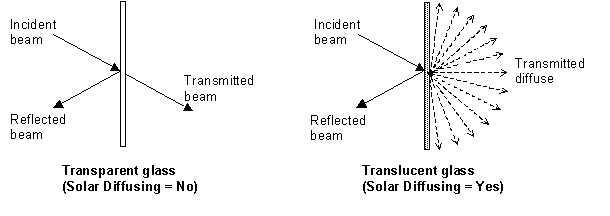
Figure 8. Comparison between transmittance properties of transparent glass (Solar Diffusing = No) and translucent glass (Solar Diffusing = Yes).
IDF examples of Spectral average and using a Spectral data set:
MATERIAL:WINDOWGLASS, GLASS - CLEAR SHEET 1 / 8 IN,
SpectralAverage, ! Optical data type
0.003, ! Thickness {m} 1/8"
0.850, ! Solar transmittance at normal incidence
0.075, ! Solar reflectance at normal incidence: front side
0.075, ! Solar reflectance at normal incidence: back side
0.901, ! Visible transmittance at normal incidence
0.081, ! Visible reflectance at normal incidence: front side
0.081, ! Visible reflectance at normal incidence: back side
0.0, ! IR transmittance at normal incidence
0.84, ! IR hemispherical emissivity: front side
0.84, ! IR hemispherical emissivity: back side
0.9; ! Conductivity {W/m-K}
WindowMaterial:Glazing ,SPECTRAL GLASS INNER PANE, ! Material name
Spectral, ! Optical data type {SpectralAverage or Spectral}
TestSpectralDataSet, ! Name of spectral data set
0.0099, ! Thickness {m}
, ! Solar transmittance at normal incidence
, ! Solar reflectance at normal incidence: front side
, ! Solar reflectance at normal incidence: back side
, ! Visible transmittance at normal incidence
, ! Visible reflectance at normal incidence: front side
, ! Visible reflectance at normal incidence: back side
0.0, ! IR transmittance at normal incidence
0.84, ! IR emissivity: front side
0.84, ! IR emissivity: back side
0.798; ! Conductivity {W/m-K}
This is an alternative way of specifying glass properties. Index of refraction and extinction coefficient are given instead of the transmittance and reflectance values used in WindowMaterial:Glazing. However, unlike WindowMaterial:Glazing, WindowMaterial:Glazing:RefractionExtinctionMethod is restricted to cases where the front and back optical properties of the glass are the same. This means it cannot be used for glass with a coating on one side. In that case WindowMaterial:Glazing should be used. Also, unlike WindowMaterial:Glazing, WindowMaterial:Glazing:RefractionExtinctionMethod does not allow input of glass wavelength-by-wavelength (spectral) properties.
The name of the glass layer. It corresponds to a layer in a window construction.
The surface-to-surface thickness of the glass (m).
Index of refraction averaged over the solar spectrum.
Extinction coefficient averaged over the solar spectrum (m-1).
Index of refraction averaged over the solar spectrum and weighted by the response of the human eye.
Extinction coefficient averaged over the solar spectrum and weighted by the response of the human eye (m-1).
Long-wave transmittance at normal incidence.
Long-wave hemispherical emissivity, assumed the same on both sides of the glass.
Thermal conductivity (W/m-K).
This is a factor that corrects for the presence of dirt on the glass. It multiplies the solar and visible transmittance at normal Incidence (which the program calculates from the input values of thickness, solar index of refraction, solar extinction coefficient, etc.) if the material is used as the outer glass layer of an exterior window or glass door. If the material is used as an inner glass layer (in double glazing, for example), the dirt correction factor is not applied because inner glass layers are assumed to be clean. Using a material with dirt correction factor < 1.0 in the construction for an interior window will result in an error message.
Representative values of the direct correction factor are shown in Table 7.
The default value of the dirt correction factor is 1.0, which means the glass is clean. It is assumed that dirt, if present, has no effect on the IR properties of the glass.
Takes values No (the default) and Yes. If No, the glass is transparent. If Yes, the glass is translucent and beam solar radiation incident on the glass is transmitted as hemispherically diffuse radiation with no beam component. Solar Diffusing = Yes should only be used on the innermost pane of glass in an exterior window; it does not apply to interior windows.
If, in the Building object, Solar Distribution = FullInteriorAndExterior, use of Solar Diffusing = Yes for glass in an exterior window will change the distribution of interior solar radiation from the window. The result is that beam solar radiation that would be transmitted by a transparent window and get absorbed by particular interior surfaces will be diffused by a translucent window and be spread over more interior surfaces. This can change the time dependence of heating and cooling loads in the zone.
In a zone with Daylighting:Detailed, translucent glazing, which is often used in skylights, will provide a more uniform daylight illuminance over the zone and will avoid patches of sunlight on the floor.
An IDF example:
WindowMaterial:Glazing:RefractionExtinctionMethod,
4MM CLEAR GLASS, !- Material name
0.004, !- Thickness {m}
1.526, !- Solar index of refraction
30.0 , !- Solar extinction coefficient (1/m)
1.526, !- Visible index of refraction
30.0 , !- Visible extinction coefficient (1/m)
0.0, !- IR transmittance at normal incidence
0.84, !- IR emissivity
0.9; !- Conductivity {W/m-K}
The optical properties of uncoated glass are sometimes specified by index of refraction, n,
and transmittance at normal incidence, T.
The following equations show how to convert from this set of values to the transmittance and reflectance values required by WindowMaterial:Glazing. These equations apply only to uncoated glass, and can be used to convert either spectral-average solar properties or spectral-average visible properties (in general, n and T are different for the solar and visible). Note that since the glass is uncoated, the front and back reflectances are the same and equal to the R that is solved for in the following equations.
Given n and T, find R:
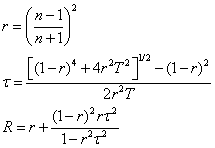
Example:
T = 0.86156
n = 1.526

Thermochromic (TC) materials have active, reversible optical properties that vary with temperature. Thermochromic windows are adaptive window systems for incorporation into building envelopes. Thermochromic windows respond by absorbing sunlight and turning the sunlight energy into heat. As the thermochromic film warms it changes its light transmission level from less absorbing to more absorbing. The more sunlight it absorbs the lower the light level going through it. By using the suns own energy the window adapts based solely on the directness and amount of sunlight. Thermochromic materials will normally reduce optical transparency by absorption and/or reflection, and are specular (maintaining vision).
A thermochromic window is defined with a Construction object which references a special layer defined with a WindowMaterial:GlazingGroup:Thermochromic object. The WindowMaterial:GlazingGroup:Thermochromic object further references a series of WindowMaterial:Glazing objects corresponding to each specification temperature of the TC layer.
This object specifies a layer of thermochromic glass, part of a thermochromic window. An example file ThermochromicWindow.idf is included in the EnergyPlus installation.
A unique user assigned name for a particular thermochromic glass material.
The temperature of the TC glass layer corresponding to the optical data of the TC layer. Unit is °C.
The window glazing (defined with WindowMaterial:Glazing) name that provides the TC glass layer performance at the above specified temperature.
IDF Examples
Construction,
window_const, !- Name
Usual Glass, !- Layer 1
AIR 6MM, !- Layer 2
TCGlazings, !- Layer 3
AIR 6MM, !- Layer 4
Usual Glass; !- Layer 5
WindowMaterial:Gas,
AIR 6MM, !- Name
Air, !- Gas Type
0.0063; !- Thickness {m}
! Added for thermochromic glazings
WindowMaterial:GlazingGroup:Thermochromic,
TCGlazings,
0 , TCGlazing0,
20, TCGlazing20,
25, TCGlazing25,
30, TCGlazing30,
35, TCGlazing35,
40, TCGlazing40,
45, TCGlazing45,
50, TCGlazing50,
55, TCGlazing55,
60, TCGlazing60,
65, TCGlazing65,
75, TCGlazing75,
85, TCGlazing85;
WindowMaterial:Glazing,
TCGlazing0, !- Name
SpectralAverage, !- Optical Data Type
, !- Window Glass Spectral Data Set Name
0.0030, !- Thickness
0.2442, !- Solar Transmittance at Normal Incidence
0.7058, !- Front Side Solar Reflectance at Normal Incidence
0.7058, !- Back Side Solar Reflectance at Normal Incidence
0.3192, !- Visible Transmittance at Normal Incidence
0.6308, !- Front Side Visible Reflectance at Normal Incidence
0.6308, !- Back Side Visible Reflectance at Normal Incidence
0.0000, !- Infrared Transmittance at Normal Incidence
0.9000, !- Front Side Infrared Hemispherical Emissivity
0.9000, !- Back Side Infrared Hemispherical Emissivity
0.0199, !- Conductivity
1.0000, !- Dirt Correction Factor for Solar and Visible Transmittance
No; !- Solar Diffusing
WindowMaterial:Glazing,
TCGlazing20, !- Name
SpectralAverage, !- Optical Data Type
, !- Window Glass Spectral Data Set Name
0.0030, !- Thickness
0.2442, !- Solar Transmittance at Normal Incidence
0.7058, !- Front Side Solar Reflectance at Normal Incidence
0.7058, !- Back Side Solar Reflectance at Normal Incidence
0.3192, !- Visible Transmittance at Normal Incidence
0.6308, !- Front Side Visible Reflectance at Normal Incidence
0.6308, !- Back Side Visible Reflectance at Normal Incidence
0.0000, !- Infrared Transmittance at Normal Incidence
0.9000, !- Front Side Infrared Hemispherical Emissivity
0.9000, !- Back Side Infrared Hemispherical Emissivity
0.0199, !- Conductivity
1.0000, !- Dirt Correction Factor for Solar and Visible Transmittance
No; !- Solar Diffusing
WindowMaterial:Glazing,
TCGlazing25, !- Name
SpectralAverage, !- Optical Data Type
, !- Window Glass Spectral Data Set Name
0.0030, !- Thickness
0.2442, !- Solar Transmittance at Normal Incidence
0.7058, !- Front Side Solar Reflectance at Normal Incidence
0.7058, !- Back Side Solar Reflectance at Normal Incidence
0.3192, !- Visible Transmittance at Normal Incidence
0.6308, !- Front Side Visible Reflectance at Normal Incidence
0.6308, !- Back Side Visible Reflectance at Normal Incidence
0.0000, !- Infrared Transmittance at Normal Incidence
0.9000, !- Front Side Infrared Hemispherical Emissivity
0.9000, !- Back Side Infrared Hemispherical Emissivity
0.0199, !- Conductivity
1.0000, !- Dirt Correction Factor for Solar and Visible Transmittance
No; !- Solar Diffusing
WindowMaterial:Glazing,
TCGlazing30, !- Name
SpectralAverage, !- Optical Data Type
, !- Window Glass Spectral Data Set Name
0.0030, !- Thickness
0.2442, !- Solar Transmittance at Normal Incidence
0.7058, !- Front Side Solar Reflectance at Normal Incidence
0.7058, !- Back Side Solar Reflectance at Normal Incidence
0.3192, !- Visible Transmittance at Normal Incidence
0.6308, !- Front Side Visible Reflectance at Normal Incidence
0.6308, !- Back Side Visible Reflectance at Normal Incidence
0.0000, !- Infrared Transmittance at Normal Incidence
0.9000, !- Front Side Infrared Hemispherical Emissivity
0.9000, !- Back Side Infrared Hemispherical Emissivity
0.0199, !- Conductivity
1.0000, !- Dirt Correction Factor for Solar and Visible Transmittance
No; !- Solar Diffusing
WindowMaterial:Glazing,
TCGlazing35, !- Name
SpectralAverage, !- Optical Data Type
, !- Window Glass Spectral Data Set Name
0.0030, !- Thickness
0.2442, !- Solar Transmittance at Normal Incidence
0.7058, !- Front Side Solar Reflectance at Normal Incidence
0.7058, !- Back Side Solar Reflectance at Normal Incidence
0.3192, !- Visible Transmittance at Normal Incidence
0.6308, !- Front Side Visible Reflectance at Normal Incidence
0.6308, !- Back Side Visible Reflectance at Normal Incidence
0.0000, !- Infrared Transmittance at Normal Incidence
0.9000, !- Front Side Infrared Hemispherical Emissivity
0.9000, !- Back Side Infrared Hemispherical Emissivity
0.0199, !- Conductivity
1.0000, !- Dirt Correction Factor for Solar and Visible Transmittance
No; !- Solar Diffusing
WindowMaterial:Glazing,
TCGlazing40, !- Name
SpectralAverage, !- Optical Data Type
, !- Window Glass Spectral Data Set Name
0.0030, !- Thickness
0.2442, !- Solar Transmittance at Normal Incidence
0.7058, !- Front Side Solar Reflectance at Normal Incidence
0.7058, !- Back Side Solar Reflectance at Normal Incidence
0.3192, !- Visible Transmittance at Normal Incidence
0.6308, !- Front Side Visible Reflectance at Normal Incidence
0.6308, !- Back Side Visible Reflectance at Normal Incidence
0.0000, !- Infrared Transmittance at Normal Incidence
0.9000, !- Front Side Infrared Hemispherical Emissivity
0.9000, !- Back Side Infrared Hemispherical Emissivity
0.0199, !- Conductivity
1.0000, !- Dirt Correction Factor for Solar and Visible Transmittance
No; !- Solar Diffusing
WindowMaterial:Glazing,
TCGlazing45, !- Name
SpectralAverage, !- Optical Data Type
, !- Window Glass Spectral Data Set Name
0.0030, !- Thickness
0.2442, !- Solar Transmittance at Normal Incidence
0.7058, !- Front Side Solar Reflectance at Normal Incidence
0.7058, !- Back Side Solar Reflectance at Normal Incidence
0.3192, !- Visible Transmittance at Normal Incidence
0.6308, !- Front Side Visible Reflectance at Normal Incidence
0.6308, !- Back Side Visible Reflectance at Normal Incidence
0.0000, !- Infrared Transmittance at Normal Incidence
0.9000, !- Front Side Infrared Hemispherical Emissivity
0.9000, !- Back Side Infrared Hemispherical Emissivity
0.0199, !- Conductivity
1.0000, !- Dirt Correction Factor for Solar and Visible Transmittance
No; !- Solar Diffusing
WindowMaterial:Glazing,
TCGlazing50, !- Name
SpectralAverage, !- Optical Data Type
, !- Window Glass Spectral Data Set Name
0.0030, !- Thickness
0.2442, !- Solar Transmittance at Normal Incidence
0.7058, !- Front Side Solar Reflectance at Normal Incidence
0.7058, !- Back Side Solar Reflectance at Normal Incidence
0.3192, !- Visible Transmittance at Normal Incidence
0.6308, !- Front Side Visible Reflectance at Normal Incidence
0.6308, !- Back Side Visible Reflectance at Normal Incidence
0.0000, !- Infrared Transmittance at Normal Incidence
0.9000, !- Front Side Infrared Hemispherical Emissivity
0.9000, !- Back Side Infrared Hemispherical Emissivity
0.0199, !- Conductivity
1.0000, !- Dirt Correction Factor for Solar and Visible Transmittance
No; !- Solar Diffusing
WindowMaterial:Glazing,
TCGlazing55, !- Name
SpectralAverage, !- Optical Data Type
, !- Window Glass Spectral Data Set Name
0.0030, !- Thickness
0.2442, !- Solar Transmittance at Normal Incidence
0.7058, !- Front Side Solar Reflectance at Normal Incidence
0.7058, !- Back Side Solar Reflectance at Normal Incidence
0.3192, !- Visible Transmittance at Normal Incidence
0.6308, !- Front Side Visible Reflectance at Normal Incidence
0.6308, !- Back Side Visible Reflectance at Normal Incidence
0.0000, !- Infrared Transmittance at Normal Incidence
0.9000, !- Front Side Infrared Hemispherical Emissivity
0.9000, !- Back Side Infrared Hemispherical Emissivity
0.0199, !- Conductivity
1.0000, !- Dirt Correction Factor for Solar and Visible Transmittance
No; !- Solar Diffusing
WindowMaterial:Glazing,
TCGlazing60, !- Name
SpectralAverage, !- Optical Data Type
, !- Window Glass Spectral Data Set Name
0.0030, !- Thickness
0.2442, !- Solar Transmittance at Normal Incidence
0.7058, !- Front Side Solar Reflectance at Normal Incidence
0.7058, !- Back Side Solar Reflectance at Normal Incidence
0.3192, !- Visible Transmittance at Normal Incidence
0.6308, !- Front Side Visible Reflectance at Normal Incidence
0.6308, !- Back Side Visible Reflectance at Normal Incidence
0.0000, !- Infrared Transmittance at Normal Incidence
0.9000, !- Front Side Infrared Hemispherical Emissivity
0.9000, !- Back Side Infrared Hemispherical Emissivity
0.0199, !- Conductivity
1.0000, !- Dirt Correction Factor for Solar and Visible Transmittance
No; !- Solar Diffusing
WindowMaterial:Glazing,
TCGlazing65, !- Name
SpectralAverage, !- Optical Data Type
, !- Window Glass Spectral Data Set Name
0.0030, !- Thickness
0.2442, !- Solar Transmittance at Normal Incidence
0.7058, !- Front Side Solar Reflectance at Normal Incidence
0.7058, !- Back Side Solar Reflectance at Normal Incidence
0.3192, !- Visible Transmittance at Normal Incidence
0.6308, !- Front Side Visible Reflectance at Normal Incidence
0.6308, !- Back Side Visible Reflectance at Normal Incidence
0.0000, !- Infrared Transmittance at Normal Incidence
0.9000, !- Front Side Infrared Hemispherical Emissivity
0.9000, !- Back Side Infrared Hemispherical Emissivity
0.0199, !- Conductivity
1.0000, !- Dirt Correction Factor for Solar and Visible Transmittance
No; !- Solar Diffusing
WindowMaterial:Glazing,
TCGlazing75, !- Name
SpectralAverage, !- Optical Data Type
, !- Window Glass Spectral Data Set Name
0.0030, !- Thickness
0.2442, !- Solar Transmittance at Normal Incidence
0.7058, !- Front Side Solar Reflectance at Normal Incidence
0.7058, !- Back Side Solar Reflectance at Normal Incidence
0.3192, !- Visible Transmittance at Normal Incidence
0.6308, !- Front Side Visible Reflectance at Normal Incidence
0.6308, !- Back Side Visible Reflectance at Normal Incidence
0.0000, !- Infrared Transmittance at Normal Incidence
0.9000, !- Front Side Infrared Hemispherical Emissivity
0.9000, !- Back Side Infrared Hemispherical Emissivity
0.0199, !- Conductivity
1.0000, !- Dirt Correction Factor for Solar and Visible Transmittance
No; !- Solar Diffusing
WindowMaterial:Glazing,
TCGlazing85, !- Name
SpectralAverage, !- Optical Data Type
, !- Window Glass Spectral Data Set Name
0.0030, !- Thickness
0.2442, !- Solar Transmittance at Normal Incidence
0.7058, !- Front Side Solar Reflectance at Normal Incidence
0.7058, !- Back Side Solar Reflectance at Normal Incidence
0.3192, !- Visible Transmittance at Normal Incidence
0.6308, !- Front Side Visible Reflectance at Normal Incidence
0.6308, !- Back Side Visible Reflectance at Normal Incidence
0.0000, !- Infrared Transmittance at Normal Incidence
0.9000, !- Front Side Infrared Hemispherical Emissivity
0.9000, !- Back Side Infrared Hemispherical Emissivity
0.0199, !- Conductivity
1.0000, !- Dirt Correction Factor for Solar and Visible Transmittance
No; !- Solar Diffusing
The temperature of the TC glass layer of a TC window at each time step.
The temperature under which the optical data of the TC glass layer are specified.
The overall properties (U-factor/SHGC/VT) of the thermochromic windows at different specification temperatures are reported in the EIO file. These window constructions are created by EnergyPlus during run time. They have similar names with suffix “_TC_XX” where XX represents a specification temperature.
This object specifies the properties of the gas between the panes of a multi-pane window. Gas Type = Custom allows you to specify the properties of gases other than air, Argon, Krypton or Xenon. There is an EnergyPlus Reference Data Set for Material:WindowGas that contains several types of gas of different thicknesses. See Material:WindowGasMixture for the case that the gas fill is a mixture of different gases.
The name of the gas fill. It refers to a layer in a window construction.
The type of gas. The choices are Air, Argon, Krypton, or Xenon. If Gas Type = Custom you can use Conductivity Coefficient A, etc. to specify the properties of a different type of gas.
The thickness (m) of the gas layer.
The following entries are used only if Gas Type = Custom. The A and B coefficients are those in the following expression that gives a property value as a function of temperature in degrees K:
![]()
The A coefficient for gas conductivity (W/m-K). Used only if Gas Type = Custom.
The B coefficient for gas conductivity (W/m-K2). Used only if Gas Type = Custom.
The A coefficient for gas viscosity (kg/m-s). Used only if Gas Type = Custom.
The B coefficient for gas viscosity (kg/m-s-K). Used only if Gas Type = Custom.
The A coefficient for gas specific heat (J/kg-K). Used only if Gas Type = Custom.
The B coefficient for gas specific heat (J/kg-K2). Used only if Gas Type = Custom.
An IDF example:
WindowMaterial:Gas,AIRGAP,
AIR, ! Gas type (Air - Argon - Krypton - Xenon - Custom)]
0.0125; ! Thickness {m} 1/2 inch
This object allows you to specify the fill between the panes of a multi-pane window to be a mixture of two, three or four different gases chosen from air, argon, krypton and xenon. It can also be used if only one type of gas in the fill. In this case you can also use WindowMaterial:Gas. Note that the fractions of gas types in the mixture should add up to 1.0.
The name of the gas mixture. It refers to a layer in a window construction.
The thickness (m) of the gas mixture layer.
The number of different types of gas in the mixture ( a value from 1 to 4)
The type of the first gas in the mixture. Choices are Air, Argon, Krypton and Xenon.
The fraction of the first gas in the mixture.
An IDF example:
WindowMaterial:GasMixture,ArgonKryptonMix,
0.0125, ! Thickness {m} 1/2 inch
2, ! Number of Gases in Mixture
Argon, ! Gas 1 Type
0.6, ! Gas 1 Fraction
Krypton, ! Gas 2 Type
0.4; ! Gas 2 Fraction
This model should be used with caution. There may be significant differences in performance between the simple window system and the usual more detailed model.
This input object differs from the other WindowMaterial objects in that it describes an entire glazing system rather than individual layers. This object is used when only very limited information is available on the glazing layers or when specific performance levels are being targeted. The layer by layer description offers superior method of modeling windows that should be used instead of this object when sufficient data are available. This object accesses a model that turns simple performance indices into a fuller model of the glazing system.
The performance indices are U-factor and Solar Heat Gain Coefficient, and optionally Visible Transmittance. The values for these performance indices can be selected by the user to represent either glazing-only windows (with no frame) or an average window performance that includes the frame. Inside the program the model produces an equivalent window glazing layer with no frame. The properties of the modeled glazing layer are reported to the EIO file using the IDF input object syntax for the WindowMaterial:Glazing input object. This equivalent layer could be reused in subsequent models if desired, however there will be important differences in the modeled window performance because the simple glazing system model includes its own special model for angular dependence when incident beam solar is not normal to the plane of the window.
When this object is referenced in a Construction object, it cannot be used with other glazing or gas material layers. Shades or blinds cannot be located between the glass, but these can be used on the inside or the outside of the glazing system. If the glazing system does have between-the-glass shades or blinds, then the U and SHGC values entered in this object should include the impacts of those layers. Adding window treatment layers such as shades or screens will alter the overall performance to be different than the performance levels prescribed in this object.
The name of the glazing system. This value is unique across all constructions.
This field describes the value for window system U-Factor, or overall heat transfer coefficient. Units are in W/m2·K. This is the rated (NFRC) value for U-factor under winter heating conditions. The U-factor is assumed to be for vertically mounted products. Although the maximum allowable input is U-7.0 W/m2·K, the effective upper limit of the glazings generated by the underlying model is around U-5.8 W/m2·K.
This field describes the value for SHGC, or solar heat gain coefficient. There are no units. This is the rated (NFRC) value for SHGC under summer cooling conditions and represents SHGC for normal incidence and vertical orientation.
This field is optional. If it is omitted, then the visible transmittance properties are taken from the solar properties. If it is included then the model includes it when developing properties for the glazing system. This is the rated (NFRC) value for visible transmittance at normal incidence.
An example of this object.
WindowMaterial:SimpleGlazingSystem,
SimpleWindow:DOUBLE PANE WINDOW , !- Name
2.716 , !- U-Factor
0.763 , !- Solar Heat Gain Coefficient
0.812 ; !- Visible Transmittance
This object specifies the properties of window shade materials. Reflectance and emissivity properties are assumed to be the same on both sides of the shade. Shades are considered to be perfect diffusers (all transmitted and reflected radiation is hemispherically-diffuse) with transmittance and reflectance independent of angle of incidence. There is an EnergyPlus Reference Data Set for WindowMaterial:Shade that contains properties of generic window shades.
Window shades can be on the inside of the window (“interior shades”), on the outside of the window (“exterior shades”), or between glass layers (“between-glass shades”). When in place, the shade is assumed to cover all of the glazed part of the window, including dividers; it does not cover any of the window frame, if present. The plane of the shade is assumed to be parallel to the glazing.
WindowMaterial:Shade can be used for diffusing materials such as drapery and translucent roller shades. For slat-type shading devices, like Venetian blinds, that have a strong angular dependence of transmission, absorption and reflection, it is better to use WindowMaterial:Blind. WindowMaterial:Screen should be used to model wire mesh insect screens where the solar and visible transmission and reflection properties vary with the angle of incidence of solar radiation.
Transmittance and reflectance values for drapery material with different color and openness of weave can be obtained from manufacturers or determined from 2001 ASHRAE Fundamentals, Chapter 30, Fig. 31.
There are two methods of assigning a shade to a window:
1) Define the construction of the window without the shade, the so-called “bare” construction.
2) Reference the bare construction in the FenestrationSurface:Detailed for the window.
3) Define the WindowMaterial:Shade.
4) Define a WindowProperty:ShadingControl for the window in which you (a) specify that this WindowMaterial:Shade is the window’s shading device and (b) specify how the shade is controlled.
1) Define the Construction of the window without the shade, the so-called “bare” construction.
2) Reference the bare construction in the FenestrationSurface:Detailed for the window.
3) Define the WindowMaterial:Shade.
4) Define another Construction, called the “shaded construction,” that includes the WindowMaterial:Shade.
5) Define a WindowProperty:ShadingControl for the window in which you (a) reference the shaded construction and (b) specify how the shade is controlled.
Note that WindowProperty:ShadingControl has to be used with either method, even if the shade is in place at all times. You will get an error message if you try to reference a shaded construction directly from FenestrationSurface:Detailed.
Name of the shade. It is referenced as an inside or outside layer in a window construction.
Transmittance averaged over the solar spectrum. Assumed independent of incidence angle.
Reflectance averaged over the solar spectrum. Assumed same on both sides of shade and independent of incidence angle.
Transmittance averaged over the solar spectrum and weighted by the response of the human eye. Assumed independent of incidence angle.
Reflectance averaged over the solar spectrum and weighted by the response of the human eye. Assumed same on both side of shade and independent of incidence angle.
Effective long-wave emissivity. Assumed same on both sides of shade. We can approximate this effective emissivity, εeff, as follows. Let η be the “openness” the shade, i.e., the ratio of the area of openings in the shade to the overall shade area (see Field: Air-Flow Permeability, below). Let the emissivity of the shade material be ε. Then
![]()
For most non-metallic materials ε is about 0.9.
Effective long-wave transmittance. Assumed independent of incidence angle. We can approximate this effective long-wave transmittance, τeff, as follows. Let η be the “openness” the shade, i.e., the ratio of the area of openings in the shade to the overall shade area. Let the long-wave transmittance of the shade material be τ. Then
![]()
For most materials τ is very close to zero, which gives
![]()
Thickness of the shade material (m). If the shade is not flat, such as for pleated pull-down shades or folded drapery, the average thickness normal to the plane of the shade should be used.
Shade material conductivity (W/m-K).
Distance from shade to adjacent glass (m). This is denoted by s in Figure 9 and Figure 10, below. If the shade is not flat, such as for pleated pull-down shades or folded drapery, the average shade-to-glass distance should be used. (The shade-to-glass distance is used in calculating the natural convective air flow between glass and shade produced by buoyancy effects.). Note used for between-glass shades.
In the following, H is the glazing height and W is the glazing width.
Effective area for air flow at the top of the shade divided by sW, the horizontal area between glass and shade (see Figures below).
Effective area for air flow at the bottom of the shade divided by sW, the horizontal area between glass and shade (see Figures below).
Effective area for air flow at the left side of the shade divided by sH, the vertical area between glass and shade (see Figures below).
Effective area for air flow at the right side of the shade divided by sH, the vertical area between glass and shade (see Figures below).
The fraction of the shade surface that is open to air flow, i.e., the total area of openings (“holes”) in the shade surface divided by the shade area, HW. If air cannot pass through the shade material, Air-Flow Permeability = 0. For drapery fabric and screens the Air-Flow Permeability can be taken as the “openness” of the fabric (see 2001 ASHRAE Fundamentals, Chapter 30, Fig. 31), which is 0.0 to 0.07 for closed weave, 0.07 to 0.25 for semi-open weave, and 0.25 and higher for open weave.
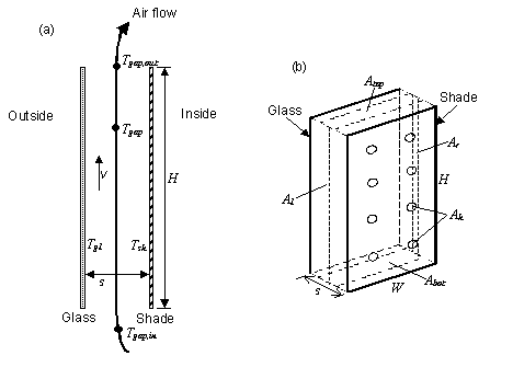
Figure 9. Vertical section (a) and perspective view (b) of glass and interior shade layers showing variables used in the gap air flow analysis. In (b), the air-flow opening areas Abot, Atop, Al, Ar and Ah are shown schematically. See Engineering Manual for definition of thermal variables.
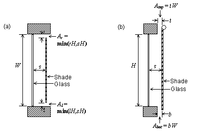
Figure 10. Examples of air-flow openings for an interior shade covering glass of height H and width W. Not to scale. (a) Horizontal section through shade with openings on the left and right sides (top view). (b) Vertical section through shade with openings at the top and bottom (side view). In (a) Left-Side Opening Multiplier = Al /sH = min(l/s,1) and Right-Side Opening Multiplier = Ar /sH = min(r/s,1). In (b) Top Opening Multiplier = Atop /sW = t/s and Bottom Opening Multiplier = Abot /sW = b/s.
An IDF example:
WindowMaterial:Shade,
DRAPES - CLOSE WEAVE MEDIUM, !- Name
0.05, !- Solar transmittance
0.3000000, !- Solar Reflectance
.05, !- Visible transmittance
0.3000000, !- Visible reflectance
0.9000000, !- Thermal Hemispherical Emissivity
0.0, !- Thermal Transmittance
0.003, !- Thickness {m}
0.1, !- Conductivity {W/m-K}
0.050, !- Shade to glass distance {m}
1.0, !- Top opening multiplier
1.0, !- Bottom opening multiplier
0.0, !- Left-side opening multiplier
0.0, !- Right-side opening multiplier
0.0; !- Air flow permeability
This object specifies the properties of a window blind consisting of flat, equally-spaced slats. Unlike window shades, which are modeled as perfect diffusers, window blinds have solar and visible transmission and reflection properties that strongly depend on slat angle and angle of incidence of solar radiation. There is an EnergyPlus Reference Data Set for WindowMaterial:Blind that contains properties of generic window blinds.
Blinds can be located on the inside of the window (“interior blinds”), on the outside of the window (“exterior blinds”), or between two layers of glass (“between-glass blinds”). When in place, the blind is assumed to cover all of the glazed part of the window, including dividers; it does not cover any of the window frame, if present. The plane of the blind is assumed to be parallel to the glazing. When the blind is retracted it is assumed to cover none of the window. The solar and thermal effects of the blind’s support strings, tapes or rods are ignored. Slat curvature, if present, is ignored.
There are two methods of assigning a blind to a window:
1) Define the construction of the window without the blind, the so-called “bare” construction.
2) Reference the bare construction in the FenestrationSurface:Detailed for the window.
3) Define the WindowMaterial:Blind.
4) Define a WindowProperty:ShadingControl for the window in which you (a) specify that this WindowMaterial:Blind is the window’s shading device and (b) specify how the blind is controlled.
1) Define the Construction of the window without the blind, the so-called “bare” construction.
2) Reference the bare construction in the FenestrationSurface:Detailed for the window.
3) Define the WindowMaterial:Blind.
4) Define another Construction, called the “shaded construction,” that includes the WindowMaterial:Blind.
5) Define a WindowProperty:ShadingControl for the window in which you (a) reference the shaded construction and (b) specify how the blind is controlled.
Note that WindowProperty:ShadingControl has to be used with either method, even if the blind is in place at all times. You will get an error message if you try to reference a construction with a blind directly from Window objects (FenestrationSurface:Detailed or Window).
Note also that WindowProperty:ShadingControl is used to determine not only when the blind is in place, but how its slat angle is controlled.
Name of the blind. It is referenced as a layer in a window construction (ref: Construction) or as a “Material Name of Shading Device” in a WindowProperty:ShadingControl object.
The choices are Horizontal and Vertical. “Horizontal” means the slats are parallel to the bottom of the window; this is the same as saying that the slats are parallel to the X-axis of the window. “Vertical” means the slats are parallel to Y-axis of the window.
The width of the slat measured from edge to edge (m). See Figure 11.
The distance between the front of a slat and the back of the adjacent slat (m). See Figure 11.
The distance between the faces of a slat (m). See Figure 11.
The angle (degrees) between the glazing outward normal and the slat outward normal, where the outward normal points away from the front face of the slat (degrees). See Figure 11.
If the WindowProperty:ShadingControl for the blind has Type of Slat Angle Control for Blinds = FixedSlatAngle, the slat angle is fixed at “Slat Angle.”
If Type of Slat Angle Control for Blinds = BlockBeamSolar, the program automatically adjusts the slat angle so as just block beam solar radiation. In this case the value of “Slat Angle” is used only when the blind is in place and there is no beam solar radiation incident on the blind.
If Type of Slat Angle Control for Blinds = ScheduledSlatAngle, the slat angle is variable. In this case “Slat Angle” is not applicable and the field should be blank.
If Type of Slat Angle Control for Blinds = FixedSlatAngle and “Slat Angle” is less than the minimum or greater than the maximum allowed by Slat Width, Slat Separation and Slat Thickness, the slat angle will be reset to the corresponding minimum or maximum and a warning will be issued.
The thermal conductivity of the slat (W/m-K).
The beam solar transmittance of the slat, assumed to be independent of angle of incidence on the slat. Any transmitted beam radiation is assumed to be 100% diffuse (i.e., slats are translucent).
The beam solar reflectance of the front side of the slat, assumed to be independent of angle of incidence (matte finish). This means that slats with a large specularly-reflective component (shiny slats) are not well modeled.
The beam solar reflectance of the back side of the slat, assumed to be independent of angle of incidence (matte finish). This means that slats with a large specularly-reflective component (shiny slats) are not well modeled.
The slat transmittance for hemispherically diffuse solar radiation. This value should equal “Slat Beam Solar Transmittance.”
The front-side slat reflectance for hemispherically diffuse solar radiation. This value should equal “Front Side Slat Beam Solar Reflectance.”
The back-side slat reflectance for hemispherically diffuse solar radiation. This value should equal “Back Side Slat Beam Solar Reflectance.”
The beam visible transmittance of the slat, assumed to be independent of angle of incidence on the slat. Any transmitted visible radiation is assumed to be 100% diffuse (i.e., slats are translucent).
The beam visible reflectance on the front side of the slat, assumed to be independent of angle of incidence (matte finish). This means that slats with a large specularly-reflective component (shiny slats) are not well modeled.
The beam visible reflectance on the front side of the slat, assumed to be independent of angle of incidence (matte finish). This means that slats with a large specularly-reflective component (shiny slats) are not well modeled.
The slat transmittance for hemispherically diffuse visible radiation. This value should equal “Slat Beam Visible Transmittance.”
The front-side slat reflectance for hemispherically diffuse visible radiation. This value should equal “Front Side Slat Beam Visible Reflectance.”
The back-side slat reflectance for hemispherically diffuse visible radiation. This value should equal “Back Side Slat Beam Visible Reflectance..”
The slat Infrared transmittance. It is zero for solid metallic, wooden or glass slats, but may be non-zero in some cases (e.g., thin plastic slats).
Front-side hemispherical emissivity of the slat. Approximately 0.9 for most materials. The most common exception is bare (unpainted) metal slats or slats finished with a metallic paint.
Back-side hemispherical emissivity of the slat. Approximately 0.9 for most materials. The most common exception is bare (unpainted) metal slats or slats finished with a metallic paint.
For interior and exterior blinds, the distance from the mid-plane of the blind to the adjacent glass (m). See Figure 11. Not used for between-glass blinds. As for window shades (ref: WindowMaterial:Shade) this distance is used in calculating the natural convective air flow between glass and blind that is produced by buoyancy effects.
The following opening multipliers are defined in the same way as for window shades (see WindowMaterial:Shade, Figure 9 and Figure 10). Note that, unlike window shades, there is no input for Air-Flow Permeability; this is automatically calculated by the program from slat angle, width and separation.
Defined as for Material:WindowShade.
Defined as for Material:WindowShade.
Defined as for Material:WindowShade.
Defined as for Material:WindowShade.
The minimum allowed slat angle (degrees). Used only if WindowProperty:ShadingControl (for the window that incorporates this blind) varies the slat angle (i.e., the WindowProperty:ShadingControl has Type of Slat Angle Control for Blinds = ScheduledSlatAngle or BlockBeamSolar). In this case, if the program tries to select a slat angle less than Minimum Slat Angle it will be reset to Minimum Slat Angle. (Note that if the Minimum Slat Angle itself is less than the minimum allowed by Slat Width, Slat Separation and Slat Thickness, it will be reset to that minimum.)
The maximum allowed slat angle (degrees). Used only if WindowProperty:ShadingControl (for the window that incorporates this blind) varies the slat angle (i.e., the WindowProperty:ShadingControl has Type of Slat Angle Control for Blinds = ScheduledSlatAngle or BlockBeamSolar). In this case, if the program tries to select a slat angle greater than Maximum Slat Angle the slat angle will be reset to Maximum Slat Angle. (Note that if the Maximum Slat Angle itself is greater than the maximum allowed by Slat Width, Slat Separation and Slat Thickness, it will be reset to that maximum.)
An IDF example:
WindowMaterial:Blind,
White Painted Metal Blind, !- Name
HORIZONTAL, !- Slat orientation
0.025 , !- Slat width (m)
0.01875 , !- Slat separation (m)
0.001 , !- Slat thickness (m)
45.0 , !- Slat angle (deg)
44.9 , !- Slat conductivity (W/m-K)
0.0 , !- Slat beam solar transmittance
0.8 , !- Front Side Slat beam solar reflectance
0.8 , !- Back Side Slat beam solar reflectance
0.0 , !- Slat diffuse solar transmittance
0.8 , !- Front Side Slat diffuse solar reflectance
0.8 , !- Back Side Slat diffuse solar reflectance
0.0 , !- Slat beam visible transmittance
0.7 , !- Front Side Slat beam visible reflectance
0.7 , !- Back Side Slat beam visible reflectance
0.0 , !- Slat diffuse visible transmittance
0.7 , !- Front Side Slat diffuse visible reflectance
0.7 , !- Back Side Slat diffuse visible reflectance
0.0 , !- Slat Infrared hemispherical transmittance
0.9 , !- Front Side Slat Infrared hemispherical emissivity
0.9 , !- Back Side Slat Infrared hemispherical emissivity
0.050 , !- Blind-to-glass distance
0.0 , !- Blind top opening multiplier
0.0 , !- Blind bottom opening multiplier
0.5 , !- Blind left-side opening multiplier
0.5 , !- Blind right-side opening multiplier
, !- Minimum slat angle (deg)
; !- Maximum slat angle (deg)
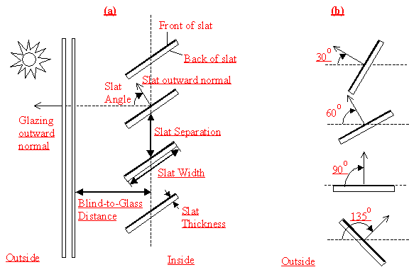
Figure 11. (a) Side view of a window blind with horizontal slats (or top view of blind with vertical slats) showing slat geometry. The front face of a slat is shown by a heavy line. The slat angle is defined as the angle between the glazing outward normal and the slat outward normal, where the outward normal points away from the front face of the slat. (b) Slat orientations for representative slat angles. The slat angle varies from 0O, when the front of the slat is parallel to the glazing and faces toward the outdoors, to 90O, when the slat is perpendicular to the glazing, to 180O, when the front of the slat is parallel to the glazing and faces toward the indoors. The minimum and maximum slat angles are determined by the slat thickness, width and separation.
This object specifies the properties of exterior window screen materials. The window screen model assumes the screen is made up of intersecting orthogonally-crossed cylinders. The surface of the cylinders is assumed to be diffusely reflecting, having the optical properties of a Lambertian surface.
The beam solar radiation transmitted through a window screen varies with sun angle and is made up of two distinct elements: a direct beam component and a reflected beam component. The direct beam transmittance component is modeled using the geometry of the screen material and the incident angle of the sun to account for shadowing of the window by the screen material. The reflected beam component is an empirical model that accounts for the inward reflection of solar beam off the screen material surface. This component is both highly directional and small in magnitude compared to the direct beam transmittance component (except at higher incident angles, for which case the magnitude of the direct beam component is small or zero and the reflected beam component, though small in absolute terms can be many times larger than the direct beam component). For this reason, the reflected beam transmittance component calculated by the model can be a. disregarded, b. treated as an additive component to direct beam transmittance (and in the same direction), or c. treated as hemispherically-diffuse transmittance based on a user input to the model.
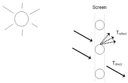
Figure 12. Direct beam and reflected beam transmittance components
The window screen “assembly” properties of overall beam solar reflectance and absorptance (including the screen material ‘cylinders’ and open area) also change with sun angle and are calculated based on the values of the beam solar transmittance components (direct and reflected components described above) and the physical properties of the screen material (i.e., screen material diameter, spacing, and reflectance).
Transmittance, reflectance, and absorptance of diffuse solar radiation are considered constant values and apply to both the front and back surfaces of the screen. These properties are calculated by the model as an average value by integrating the screen’s beam solar properties over a quarter hemisphere of incident radiation. Long-wave emissivity is also assumed to be the same for both sides of the screen.
There is an EnergyPlus Reference Data Set for WindowMaterial:Screen that contains properties for generic window screens. Window screens of this type can only be used on the outside surface of the window (“exterior screens”). When in place, the screen is assumed to cover all of the glazed part of the window, including dividers; it does not cover any of the window frame, if present. The plane of the screen is assumed to be parallel to the glazing.
WindowMaterial:Screen can be used to model wire mesh insect screens where the solar and visible transmission and reflection properties vary with the angle of incidence of solar radiation. For diffusing materials such as drapery and translucent roller shades it is better to use the WindowMaterial:Shade object. For slat-type shading devices like Venetian blinds, which have solar and visible transmission and reflection properties that strongly depend on slat angle and angle of incidence of solar radiation, it is better to use WindowMaterial:Blind.
There are two methods of assigning a screen to a window:
1) Define the construction of the window without the screen, the so-called “bare” construction.
2) Reference the bare construction in the FenestrationSurface:Detailed for the window.
3) Define the WindowMaterial:Screen object.
4) Define a WindowProperty:ShadingControl for the window in which you (a) specify that this Material:WindowScreen is the window’s shading device, and (b) specify how the screen is controlled.
1) Define the Construction of the window without the screen, the so-called “bare” construction.
2) Reference the bare construction in the FenestrationSurface:Detailed for the window.
3) Define the WindowMaterial:Screen object.
4) Define another Construction, called the “shaded construction,” that includes the WindowMaterial:Screen.
5) Define a WindowProperty:ShadingControl for the window in which you (a) reference the shaded construction, and (b) specify how the screen is controlled.
Note that WindowProperty:ShadingControl has to be used with either method, even if the screen is in place at all times. You will get an error message if you try to reference a shaded construction directly from a FenestrationSurface:Detailed object.
Enter a unique name for the screen. This name is referenced as an outside layer in a window construction.
This input specifies the method used to account for screen-reflected beam solar radiation that is transmitted through the window screen (as opposed to being reflected back outside the building). Since this inward reflecting beam solar is highly directional and is not modeled in the direction of the actual reflection, the user is given the option of how to account for the directionality of this component of beam solar transmittance. Valid choices are DoNotModel, ModelAsDirectBeam (i.e., model as an additive component to direct solar beam and in the same direction), or ModelAsDiffuse (i.e., model as hemispherically-diffuse radiation). The default value is ModelAsDiffuse.
This input specifies the solar reflectance (beam-to-diffuse) of the screen material itself (not the effective value for the overall screen “assembly” including open spaces between the screen material). The outgoing diffuse radiation is assumed to be Lambertian (distributed angularly according to Lambert’s cosine law). The solar reflectance is assumed to be the same for both sides of the screen. This value must be from 0 to less than 1.0. In the absence of better information, the input value for diffuse solar reflectance should match the input value for diffuse visible reflectance.
This input specifies the visible reflectance (beam-to-diffuse) of the screen material itself (not the effective value for the overall screen “assembly” including open spaces between the screen material) averaged over the solar spectrum and weighted by the response of the human eye. The outgoing diffuse radiation is assumed to be Lambertian (distributed angularly according to Lambert’s cosine law). The visible reflectance is assumed to be the same for both sides of the screen. This value must be from 0 to less than 1.0.
If diffuse visible reflectance for the screen material is not available, then the following guidelines can be used to estimate this value:
Dark-colored screen (e.g., charcoal): 0.08 – 0.10
Medium-colored screen (e.g., gray): 0.20 – 0.25
Light-colored screen (e.g., bright aluminum): 0.60 – 0.65
Commercially-available gray scale or grayscale reflecting chart references can be purchased for improved accuracy in estimating visible reflectance (by visual comparison of screen reflected brightness with that of various known-reflectance portions of the grayscale).
Long-wave emissivity ε of the screen material itself (not the effective value for the overall screen “assembly” including open spaces between the screen material). The emissivity is assumed to be the same for both sides of the screen.
For most non-metallic materials, ε is about 0.9. For metallic materials, ε is dependent on material, its surface condition, and temperature. Typical values for metallic materials range from 0.05 – 0.1 with lower values representing a more finished surface (e.g. low oxidation, polished surface). Material emissivities may be found in Table 5 from the 2005 ASHRAE Handbook of Fundamentals, page 3.9. The value for this input field must be between 0 and 1, with a default value of 0.9 if this field is left blank.
Screen material conductivity (W/m-K). This input value must be greater than 0. The default value is 221 W/m-K (aluminum).
The spacing, S, of the screen material (m) is the distance from the center of one strand of screen to the center of the adjacent one. The spacing of the screen material is assumed to be the same in both directions (e.g., vertical and horizontal). This input value must be greater than the non-zero screen material diameter. If the spacing is different in the two directions, use the average of the two values.
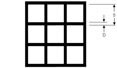
Figure 13. Screen Material Spacing and Diameter
The diameter, D, of individual strands or wires of the screen material (m). The screen material diameter is assumed to be the same in both directions (e.g., vertical and horizontal). This input value must be greater than 0 and less than the screen material spacing. If the diameter is different in the two directions, use the average of the two values.
Distance from the window screen to the adjacent glass surface (m). If the screen is not flat, the average screen to glass distance should be used. The screen-to-glass distance is used in calculating the natural convective air flow between the glass and the screen produced by buoyancy effects. This input value must be from 0.001 m to 1 m, with a default value of 0.025 m if this field is left blank.
Effective area for air flow at the top of the screen divided by the horizontal area between the glass and screen (see the same field for the Material:WindowShade object for additional description). The opening multiplier fields can be used to simulate a shading material that is offset from the window frame. Since window screens are typically installed against the window frame, the default value is equal to 0.This input value can range from 0 to 1.
Effective area for air flow at the bottom of the screen divided the horizontal area between the glass and screen (see the same field for the Material:WindowShade object for additional description). The opening multiplier fields can be used to simulate a shading material that is offset from the window frame. Since window screens are typically installed against the window frame, the default value is equal to 0. This input value can range from 0 to 1.
Effective area for air flow at the left side of the screen divided the vertical area between the glass and screen (see the same field for the Material:WindowShade object for additional description). The opening multiplier fields can be used to simulate a shading material that is offset from the window frame. Since window screens are typically installed against the window frame, the default value is equal to 0. This input value can range from 0 to 1.
Effective area for air flow at the right side of the screen divided the vertical area between the glass and screen (see the same field for the Material:WindowShade object for additional description). The opening multiplier fields can be used to simulate a shading material that is offset from the window frame. Since window screens are typically installed against the window frame, the default value is equal to 0. This input value can range from 0 to 1.
Angle of resolution, in degrees, for the overall screen beam transmittance (direct and reflected) output map. The comma-separated variable file eplusscreen.csv (Ref. OutputDetailsandExamples.pdf) will contain the direct beam and reflected beam solar radiation that is transmitted through the window screen as a function of incident sun angle (0 to 90 degrees relative solar azimuth and 0 to 90 degrees relative solar altitude) in sun angle increments specified by this input field. The default value is 0, which means no transmittance map is generated. Other valid choice inputs are 1, 2, 3 and 5 degrees.
An IDF example for this object, along with Construction and WindowProperty:ShadingControl objects, is shown below:
WindowMaterial:Screen,
EXTERIOR SCREEN, !- Name
ModelAsDiffuse, !- Reflected Beam Transmittance Accounting Method
0.6, !- Diffuse Solar Reflectance
0.6, !- Diffuse Visible Reflectance
0.9, !- Thermal Hemispherical Emissivity
221.0, !- Conductivity {W/m-K}
0.00154, !- Screen Material Spacing (m)
0.000254, !- Screen Material Diameter (m)
0.025, !- Screen-to-Glass Distance {m}
0.0, !- Top Opening Multiplier
0.0, !- Bottom Opening Multiplier
0.0, !- Left-Side Opening Multiplier
0.0, !- Right-Side Opening Multiplier
0; !- Angle of Resolution for Output Map {deg}
Construction,
DOUBLE PANE WITHOUT SCREEN, !- Name
GLASS - CLEAR SHEET 1 / 8 IN, !- Outside Layer
WinAirB1 - AIRSPACE RESISTANCE, !- Layer #2
GLASS - CLEAR SHEET 1 / 8 IN; !- Layer #3
WindowProperty:ShadingControl,
DOUBLE PANE WITH SCREEN, !- User Supplied Shading Control Name
ExteriorScreen, !- Shading Type
, !- Name of construction with shading
AlwaysOn, !- Shading Control Type
ScreenSchedule, !- Schedule Name
20.0, !- SetPoint {W/m2, W or deg C}
YES, !- Shading Control Is Scheduled
NO, !- Glare Control Is Active
EXTERIOR SCREEN, !- Material Name of Shading Device
, !- Type of Slat Angle Control for Blinds
; !- Slat Angle Schedule Name
This definition must be used in order to simulate the green roof (ecoroof) model. The material becomes the outside layer in a green roof construction (see example below). In the initial release of the green roof model, only one material may be used as a green roof layer though, of course, several constructions using that material may be used. In addition, the model has only been tested with the ConductionTransferFunction solution algorithm – a warning will be issued for other solution algorithm choices.
This field is a unique reference name that the user assigns to a particular ecoroof material. This name can then be referred to by other input data.
This field defines the height of plants in units of meters. This field is limited to values in the range 0.005 < Height < 1.00 m. Default is .2 m.
This is the projected leaf area per unit area of soil surface. This field is dimensionless and is limited to values in the range of 0.001 < LAI < 5.0. Default is 1.0.
This field represents the fraction of incident solar radiation that is reflected by the individual leaf surfaces (albedo). Solar radiation includes the visible spectrum as well as infrared and ultraviolet wavelengths. Values for this field must be between 0.05 and 0.5. Default is .22. Typical values are .18 to .25.
This field is the ratio of thermal radiation emitted from leaf surfaces to that emitted by an ideal black body at the same temperature. This parameter is used when calculating the long wavelength radiant exchange at the leaf surfaces. Values for this field must be between 0.8 and 1.0 (with 1.0 representing “black body” conditions). Default is .95.
This field represents the resistance of the plants to moisture transport. It has units of s/m. Plants with low values of stomatal resistance will result in higher evapotranspiration rates than plants with high resistance. Values for this field must be in the range of 50.0 to 300.0. Default is 180.
This field is a unique reference name that the user assigns to the soil layer for a particular ecoroof. This name can then be referred to by other input data. Default is Green Roof Soil.
This alpha field defines the relative roughness of a particular material layer. This parameter only influences the convection coefficients, more specifically the exterior convection coefficient. A keyword is expected in this field with the options being “VeryRough”, “Rough”, “MediumRough”, “MediumSmooth”, “Smooth”, and “VerySmooth” in order of roughest to smoothest options. Default is MediumRough.
This field characterizes the thickness of the material layer in meters. This should be the dimension of the layer in the direction perpendicular to the main path of heat conduction. This value must be a positive. Depths of .15m (6 inches) and .30m (12 inches) are common. Default if this field is left blank is .1. Maximum is .7m. Must be greater than .05 m.
This field is used to enter the thermal conductivity of the material layer. Units for this parameter are W/(m-K). Thermal conductivity must be greater than zero. Typical soils have values from .3 to .5. Minimum is .2 (specified in IDD). Default is .35 and maximum (in IDD) is 1.5.
This field is used to enter the density of the material layer in units of kg/m3. Density must be a positive quantity. Typeical soils range from 400 to 1000 (dry to wet). Minimum is 300, maximum is 2000 and default if field is left blank is 1100.
This field represents the specific heat of the material layer in units of J/(kg-K). Note that these units are most likely different than those reported in textbooks and references which tend to use kJ/(kg-K) or J/(g-K). They were chosen for internal consistency within EnergyPlus. Only positive values of specific heat are allowed.
The thermal absorptance field in the Material input syntax represents the fraction of incident long wavelength radiation that is absorbed by the material. This parameter is used when calculating the long wavelength radiant exchange between various surfaces and affects the surface heat balances (both inside and outside as appropriate). For long wavelength radiant exchange, thermal emissivity and thermal emittance are equal to thermal absorptance. Values for this field must be between 0.0 and 1.0 (with 1.0 representing “black body” conditions). Typical values are from .9 to .98.
The solar absorptance field in the Material input syntax represents the fraction of incident solar radiation that is absorbed by the material. Solar radiation includes the visible spectrum as well as infrared and ultraviolet wavelengths. This parameter is used when calculating the amount of incident solar radiation absorbed by various surfaces and affects the surface heat balances (both inside and outside as appropriate). If solar reflectance (or reflectivity) data is available, then absorptance is equal to 1.0 minus reflectance (for opaque materials). Values for this field must be between 0.0 and 1.0. Typical values are from .6 to .85.
The visible absorptance field in the Material input syntax represents the fraction of incident visible wavelength radiation that is absorbed by the material. Visible wavelength radiation is slightly different than solar radiation in that the visible band of wavelengths is much more narrow while solar radiation includes the visible spectrum as well as infrared and ultraviolet wavelengths. This parameter is used when calculating the amount of incident visible radiation absorbed by various surfaces and affects the surface heat balances (both inside and outside as appropriate) as well as the daylighting calculations. If visible reflectance (or reflectivity) data is available, then absorptance is equal to 1.0 minus reflectance (for opaque materials). Values for this field must be between 0.5 and 1.0.
The field allows for user input of the saturation moisture content of the soil layer. Maximum moisture content is typically less than .5. Range is (.1,.5] with the default being .3.
The field allows for user input of the residual moisture content of the soil layer. Default is .01, range is [.01,.1].
The field allows for user input of the initial moisture content of the soil layer. Range is (.05, .5] with the defaulte being .1.
The field allows for two models to be selected: Simple or Advanced.
Simple is the original Ecoroof model - based on a constant diffusion of moisture through the soil. This model starts with the soil in two layers. Every time the soil properties update is called, it will look at the two soils moisture layers and asses which layer has more moisture in it. It then takes moisture from the higher moisture layer and redistributes it to the lower moisture layer at a constant rate.
Advanced is the later Ecoroof model. If you use it, you will need to increase your number of timesteps in hour for the simulation with a recommended value of 20. This moisture transport model is based on a project which looked at the way moisture transports through soil. It uses a finite difference method to divide the soil into layers (nodes). It redistributes the soil moisture according the model described in:
Marcel G Schaap and Martinus Th. van Genuchten, 2006, 'A modified Maulem-van Genuchten Formulation for Improved Description of the Hydraulic Conductivity Near Saturation’, Vadose Zone Journal 5 (1), p 27-34.
An IDF example:
Material:RoofVegetation,
BaseEco, !- Name
0.5, !- Height of Plants {m}
5, !- Leaf Area Index {dimensionless}
0.2, !- Leaf Reflectivity {dimensionless}
0.95, !- Leaf Emissivity
180, !- Minimum Stomatal Resistance {s/m}
EcoRoofSoil, !- Soil Layer Name
MediumSmooth, !- Roughness
0.18, !- Thickness {m}
0.4, !- Conductivity of Dry Soil {W/m-K}
641, !- Density of Dry Soil {kg/m3}
1100, !- Specific Heat of Dry Soil {J/kg-K}
0.95, !- Thermal Absorptance
0.8, !- Solar Absorptance
0.7, !- Visible Absorptance
0.4, !- Saturation Volumetric Moisture Content of the Soil Layer
0.01, !- Residual Volumetric Moisture Content of the Soil Layer
0.2, !- Initial Volumetric Moisture Content of the Soil Layer
Advanced; !- Moisture Diffusion Calculation Method
Material:RoofVegetation,
LowLAI, !- Name
0.5, !- Height of Plants {m}
0.5, !- Leaf Area Index {dimensionless}
0.2, !- Leaf Reflectivity {dimensionless}
0.95, !- Leaf Emissivity
180, !- Minimum Stomatal Resistance {s/m}
EcoRoofSoil, !- Soil Layer Name
MediumSmooth, !- Roughness
0.18, !- Thickness {m}
0.4, !- Conductivity of Dry Soil {W/m-K}
641, !- Density of Dry Soil {kg/m3}
1100, !- Specific Heat of Dry Soil {J/kg-K}
0.95, !- Thermal Absorptance
0.8, !- Solar Absorptance
0.7, !- Visible Absorptance
0.4, !- Saturation Volumetric Moisture Content of the Soil Layer
0.01, !- Residual Volumetric Moisture Content of the Soil Layer
0.2, !- Initial Volumetric Moisture Content of the Soil Layer
Advanced; !- Moisture Diffusion Calculation Method
And construction using the ecoroof material:
Construction,
ASHRAE 90.1-2004_Sec 5.5-2_Roof, !- Name
BaseEco, !- Outside Layer
ASHRAE 90.1-2004_Sec 5.5-2_Roof Insulation_1, !- Layer #2
ASHRAE 90.1-2004_Sec 5.5-2_MAT-METAL; !- Layer #3
With the MaterialProperty:GlazingSpectralData object, you can specify the wavelength-by-wavelength transmittance and reflectance properties of a glass material. To determine the overall optical properties of a glazing system (solar and visible transmittance and solar absorptance vs. angle of incidence) EnergyPlus first calculates transmittance and absorptance vs. angle of incidence for each wavelength. This is then weighted by a standard solar spectrum to get the solar transmittance and absorptance vs. angle of incidence (for use in the solar heat gain calculations), and further weighted by the response of the human eye to get the visible transmittance vs. angle of incidence (for use in the daylighting calculation).
MaterialProperty:GlazingSpectralData should be used for multi-pane windows when one or more of the glass layers is spectrally selective, i.e., the transmittance depends strongly on wavelength. An example is glass with a coating that gives high transmittance in the daylight part of the solar spectrum (roughly 0.4 to 0.7 microns) and low transmittance at longer wavelengths, thus providing better solar heat gain control than uncoated glass. If spectral data is not used in case, the overall optical properties of the glazing system that EnergyPlus calculates will not be correct.
You can input up to 450 sets of values for wavelengths covering the solar spectrum. Each set consists of {wavelength (microns), transmittance, front reflectance, back reflectance}
Spectral data of this kind are routinely measured by glass manufacturers. Data sets for over 800 commercially available products are contained in an Optical Data Library maintained by the Windows Group at Lawrence Berkeley National Laboratory. This library can be downloaded from http://windows.lbl.gov/. You will have to edit entries from this library to put them in the format required by the EnergyPlus WindowGlassSpectralData object.
An alternative to using the MaterialProperty:GlazingSpectralData object is to run the WINDOW 5 window analysis program. This program has built-in access to the Optical Data Library and let’s you easily create customized, multi-layer glazing systems that can be exported for use in EnergyPlus. For more details, see “StormWindow”.
The name of the spectral data set. It is referenced by WindowMaterial:Glazing when Optical Data Type = Spectral.
Sets of values for wavelengths covering the solar spectrum (from about 0.25 to 2.5 microns [10-6 m]). Each set consists of
{wavelength (microns), transmittance, front reflectance, back reflectance}
The wavelength values must be in ascending order. The transmittance and reflectance values are at normal incidence. “Front reflectance” is the reflectance for radiation striking the glass from the outside, i.e., from the side opposite the zone in which the window is defined. “Back reflectance” is the reflectance for radiation striking the glass from the inside, i.e., from the zone in which the window is defined. Therefore, for exterior windows, “front” is the side closest to the outdoors and “back” is the side closest to the zone in which the window is defined. For interior windows, “front” is the side closest to the adjacent zone and “back” is the side closest to the zone in which the window is defined.
An IDF example:
MaterialProperty:GlazingSpectralData,
TestSpectralDataSet,
! { from WINDOW 4 library }
! { actual 9.91mm clear laminate: 15_mil PVB, ID:37966/50032-39-9 } 10.38
! { conductivity PVB adjusted, W/M/K } 0.798
! { thermal IR transmittance, assumed } tir=0.00
! { thermal IR hemispherical emittance, assumed } emis= 0.84 0.84
! WL T Rfront Rback
.300, 0.000, 0.045, 0.045,
.310, 0.000, 0.044, 0.044,
.320, 0.000, 0.044, 0.044,
.330, 0.000, 0.042, 0.042,
.340, 0.000, 0.041, 0.041,
.350, 0.000, 0.040, 0.040,
<reduced for brevity>
2.450, 0.200, 0.040, 0.040,
2.500, 0.214, 0.039, 0.039;
For walls, roofs, floors, windows, and doors, constructions are “built” from the included materials. Each layer of the construction is a material name listed in order from “outside” to “inside”. Up to ten layers (eight for windows) may be specified (one of the few limitations in EnergyPlus!). “Outside” is the layer furthest away from the Zone air (not necessarily the outside environment). “Inside” is the layer next to the Zone air. In the example floor below, for example, the outside layer is the acoustic tile below the floor, the next layer is the air space above the tile, and the inside layer is the concrete floor deck.
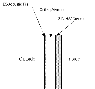
Figure 14. Example Floor Construction illustration.
Window constructions are similarly built up from items in the Window Materials set using similar layers.. See Figure 15. Illustration for material ordering in windows, which shows the case where an interior shading layer such as a blind is present. The gap between the inside glass layer (layer #3) and the interior shading layer is not entered. Similarly, for an exterior shading layer, the gap between the outside glass layer and the shading layer is not entered.
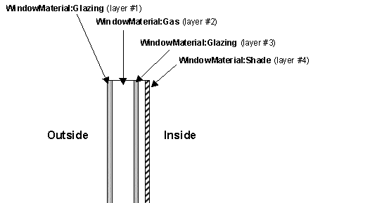
Figure 15. Illustration for material ordering in windows.
However, for a between-glass shading device the gaps on either side of the shading layer must be entered and they must have the same gas type. In addition, the gap widths with and without the between-glass shading layer must be consistent (see Figure 16).
A maximum of four glass layers and one shading layer is allowed. A gas layer must always separate adjacent glass layers in a multi-pane glazing without a between-glass shading layer.
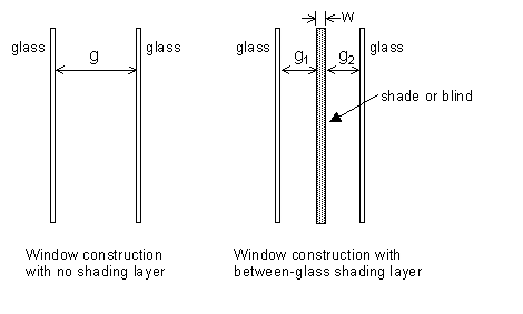
Figure 16. Window construction with and without a between-glass shading layer. Shown are gap widths g, g1 and g2, and shading layer width, w. An error will result if g1+g2+w is not equal to g, where w is zero for a blind and greater than zero for a shade.
Outside and inside air film resistances are never given as part of a construction definitions since they are calculated during the EnergyPlus simulation. Note also that constructions are assumed to be one-dimensional in a direction perpendicular to the surface.
This field is a user specified name that will be used as a reference by other input syntax. For example, a heat transfer surface (ref: Building Surfaces) requires a construction name to define what the make-up of the wall is. This name must be identical to one of the Construction definitions in the input data file.
Each construction must have at least one layer. This field defines the material name associated with the layer on the outside of the construction—outside referring to the side that is not exposed to the zone but rather the opposite side environment, whether this is the outdoor environment or another zone. Material layers are defined based on their thermal properties elsewhere in the input file (ref: Material and Material Properties and Materials for Glass Windows and Doors). As noted above, the outside layer should NOT be a film coefficient since EnergyPlus will calculate outside convection and radiation heat transfer more precisely.
The next fields are optional and the number of them showing up in a particular Construction definition depends solely on the number of material layers present in that construction. The data expected is identical to the outside layer field (see previous field description). The order of the remaining layers is important and should be listed in order of occurrence from the one just inside the outside layer until the inside layer is reached. As noted above, the inside layer should NOT be a film coefficient since EnergyPlus will calculate inside convection and radiation heat transfer more precisely.
IDF Example (floor construction):
Construction, FLOOR38, ! Material layer names follow:
E5 - ACOUSTIC TILE,
E4 - CEILING AIRSPACE,
C12 - 2 IN HW CONCRETE;
IDF Example (window construction, no shade):
Construction, DOUBLE PANE WINDOW, !- Material layer names follow:
GLASS - CLEAR SHEET 1 / 8 IN,
WinAirB1 - AIRSPACE RESISTANCE,
GLASS - CLEAR SHEET 1 / 8 IN;
IDF Example (window construction, with interior shade):
Construction, DOUBLE PANE WITH ROLL SHADE, !- Material layer names follow:
GLASS - CLEAR SHEET 1 / 8 IN,
WinAirB1 - AIRSPACE RESISTANCE,
GLASS - CLEAR SHEET 1 / 8 IN,
ROLL SHADE - LIGHT
Site:GroundTemperature:FCfactorMethod is used only by the underground walls or slabs-on-grade or underground floors defined with C-factor (Construction:CfactorUndergroundWall) and F-factor (Construction:FfactorGroundFloor) method for code compliance calculations where detailed construction layers are unknown. Only one such ground temperature object can be included. The monthly ground temperatures for this object are close to the monthly outside air temperatures delayed by three months. If user does not input this object in the IDF file, it will be defaulted to the 0.5m set of monthly ground temperatures from the weather file if they are available.
Each numeric field is the monthly ground temperature (degrees Celsius) used for the indicated month (January=1st field, February=2nd field, etc.)
And, the IDF example:
Site:GroundTemperature:FCfactorMethod, 9.5,3.5,-0.7,-1.7,-0.6,3.6,9.3,14,18.2,22.7,21.2,16.8;
Building energy code and standards like ASHRAE 90.1, 90.2 and California Title 24 require the underground wall constructions and slabs-on-grade or underground floors not to exceed certain maximum values of C-factor and F-factor, which do not specify detailed layer-by-layer materials for the constructions.
A simplified approach is introduced to create equivalent constructions and model the ground heat transfer through underground walls and ground floors for the building energy code compliance calculations. The approach is to create constructions based on the user defined C or F factor with two layers: one concrete layer (0.15 m thick) with thermal mass, and one fictitious insulation layer with no thermal mass. Three new objects were created for such purpose: Construction:CfactorUndergroundWall, Construction:FfactorGroundFloor, and Site:GroundTemperature:FCfactorMethod. Details of the approach are described in the Engineering Reference document. The wall and floor construction objects are described in this section; the ground temperature object is described with the other ground temperature objects.
When a underground wall or ground floor surface (BuildingSurface:Detailed, Floor:Detailed, and Wall:Detailed) references one of the two construction objects, its field ‘Outside Boundary Condition’ needs to be set to GroundFCfactorMethod. For simple (rectangular) wall and floor objects, the outside boundary condition is inferred from the construction type.
The Site:GroundTemperature:FCfactorMethod is described in the section for ground temperatures, the following section describes the two new construction objects.
This input object differs from the usual wall construction object in that it describes an entire construction rather than individual layers. This object is used when only the wall height (depth to the ground) and the C-factor are available. This object accesses a model that creates an equivalent layer-by-layer construction for the underground wall to approximate the heat transfer through the wall considering the thermal mass of the earth soil.
This object is referenced by underground wall surfaces with their fields ‘Outside Boundary Condition’ set to GroundFCfactorMethod.
The name of the underground wall construction.
C-Factor is the time rate of steady-state heat flow through unit area of the construction, induced by a unit temperature difference between the body surfaces. The C-Factor unit is W/m2·K. The C-factor does not include soil or air films. ASHRAE Standard 90.1 and California Title 24 specify maximum C-factors for underground walls depending on space types and climate zones.
This field describes the height of the underground wall, i.e. the depth to the ground surface. The unit is meters.
IDF Example:
Construction:CfactorUndergroundWall,
CfactorUGWall,
0.436, ! C-factor (W/m2K), does not include soil or air films
4.57; ! Height (m)
BuildingSurface:Detailed,
Zn001:Wall001, !- Name
Wall, !- Surface Type
CfactorUGWall, !- Construction Name
ZONE ONE, !- Zone Name
GroundFCfactorMethod, !- Outside Boundary Condition
, !- Outside Boundary Condition Object
NoSun, !- Sun Exposure
NoWind, !- Wind Exposure
0.0, !- View Factor to Ground
4, !- Number of Vertices
0.0,0.0,4.572, !- X,Y,Z ==> Vertex 1
0.0,0.0,0.0, !- X,Y,Z ==> Vertex 2
15.24,0.0,0.0, !- X,Y,Z ==> Vertex 3
15.24,0.0,4.572; !- X,Y,Z ==> Vertex 4
This input object differs from the usual ground floor construction object in that it describes an entire construction rather than individual layers. This object is used when only the floor area, exposed perimeter, and the F-factor are available. This object accesses a model that creates an equivalent layer-by-layer construction for the slab-on-grade or underground floor to approximate the heat transfer through the floor considering the thermal mass of the earth soil.
This object is referenced by slab-on-grade or underground floor surfaces with their fields ‘Outside Boundary Condition’ set to GroundFCfactorMethod.
The name of the ground floor construction.
F-Factor represents the heat transfer through the floor, induced by a unit temperature difference between the outside and inside air temperature, on the per linear length of the exposed perimeter of the floor. The unit for this input is W/m·K. ASHRAE Standard 90.1 and California Title 24 specify maximum F-factors for slab-on-grade or underground floors depending on space types and climate zones.
This field describes the area (in square meters) of the slab-on-grade or underground floor.
This field describes the exposed (direct contact with ambient air) perimeter (in meters) of the slab-on-grade or underground floor.
IDF Example:
Construction:FfactorGroundFloor,
slabconst,
0.12, !F-factor in W/m-K
232.26, !Area in m2
61.0; !Exposed perimeter in m
BuildingSurface:Detailed,
Zn001:Flr001, !- Name
Floor, !- Surface Type
slabconst, !- Construction Name, FLOOR
ZONE ONE, !- Zone Name
GroundFCfactorMethod, !- Outside Boundary Condition, Surface
, !- Outside Boundary Condition Object, Zn001:Flr001
NoSun, !- Sun Exposure
NoWind, !- Wind Exposure
0, !- View Factor to Ground
4, !- Number of Vertices
15.24,0.0,0.0, !- X,Y,Z ==> Vertex 1
0.0,0.0,0.0, !- X,Y,Z ==> Vertex 2
0.0,15.240,0.0, !- X,Y,Z ==> Vertex 3
15.24,15.24,0.0; !- X,Y,Z ==> Vertex 4
If the ConductionFiniteDifferenceSimplified solution algorithm is being used and there is a surface (that is, construction) that should be simulated with the detailed node arrangement, it should be specified with this object. If you have similar constructions and you want some to be using the detailed algorithm and some to use the simplified (two-node) algorithm, you must create different constructions for each case.
This is the name of the construction that will be simulated with the detailed algorithm. If there are other surfaces that use the same construction, this one should be given a different and unique name.
Input Example
Construction:UseHBAlgorithmCondFDDetailed,
InsidePCMConstruction;
In some cases such as radiant systems, a construction will actually have resistance wires or hydronic tubing embedded within the construction. Heat is then either added or removed from this building element to provide heating or cooling to the zone in question. In the case of building-integrated photovoltaics, the energy removed in the form of electricity will form a sink. It is possible to enter such constructions into EnergyPlus with the syntax described below. The definition is similar to the Construction definition with a few additions related to radiant or other systems that will lead to source/sink terms. The internal source capability is available with both the ConductionTransferFunction and ConductionFiniteDifference solution algorithms. The only difference is that the two dimensional pipe arrangements are not available to ConductionFiniteDifference. Those fields are ignored in that implementation.
This field is a user specified name that will be used as a reference by other input syntax. For example, a heat transfer surface (ref: Building Surfaces) requires a construction name to define what the make-up of the wall is.
This field is an integer that relates the location of the heat source or sink. The integer refers to the list of material layers that follow later in the syntax and determines the layer after which the source is present. If a source is embedded within a single homogenous layer (such as concrete), that layer should be split into two layers and the source added between them. For example, a value of “2” in this field tells EnergyPlus that the source is located between the second and third material layers listed later in the construction description (see layer fields below).
The nature of this field is similar to the source interface parameter (see previous field) in that it is an integer, refers to the list of material layers that follow, and defines a location after the layer number identified by the user-defined number. In this case, the user is specifying the location for a separate temperature calculation rather than the location of the heat source/sink. This feature is intended to allow users to calculate a temperature within the construction. This might be important in a radiant cooling system where condensation could be a problem. This temperature calculation can assist users in making that determination in absence of a full heat and mass balance calculation.
This field is also an integer and refers to the detail level of the calculation. A value of “1” states that the user is only interested in a one-dimensional calculation. This is appropriate for electric resistance heating and for hydronic heating (when boiler/hot water heater performance is not affected by return and supply water temperatures). A value of “2” will trigger a two-dimensional solution for this surface only. This may be necessary for hydronic radiant cooling situations since chiller performance is affected by the water temperatures provided.
A few things should be noted about requesting two-dimensional solutions. First, the calculation of the conduction transfer functions (CTF) is fairly intensive and will require a significant amount of computing time. Second, the solution regime is two-dimensional internally but it has a one-dimensional boundary condition imposed at the inside and outside surface (i.e., surface temperatures are still isothermal is if the surface was one-dimensional).
This field defines how far apart in meters the hydronic tubing or electrical resistance wires are spaced in the direction perpendicular to the main direction of heat transfer. Note that this parameter is only used for two-dimensional solutions (see previous field).
Each construction must have at least one layer. This field defines the material name associated with the layer on the outside of this construction—outside referring to the side that is not exposed to the zone but rather the opposite side environment, whether this is the outdoor environment or another zone. Material layers are defined based on their thermal properties elsewhere in the input file (ref: Material and Material Properties and Materials for Glass Windows and Doors). As noted above, the outside layer should NOT be a film coefficient since EnergyPlus will calculate convection and radiation heat transfer more precisely.
The next fields are optional and the number of them showing up in a particular Construction definition depends solely on the number of material layers present in that particular construction. The data expected is identical to the outside layer field (see previous field description). The order of the remaining layers is important and should be listed in order of occurrence from the one just inside the outside layer until the inside layer is reached. As noted above, the inside layer should NOT be a film coefficient since EnergyPlus will calculate convection and radiation heat transfer more precisely.
Standard constructions in EnergyPlus are built with the materials and layers described earlier. However, some configurations will not be adequately represented by using this approach. The Reference Data Set CompositeWallConstructions.idf contains constructions and associated materials for a set of composite walls. These are walls—such as stud walls—that have complicated heat-flow paths so that the conduction is two- or three-dimensional. Thermal bridges are one of the common terms for these complicated heat-flow paths; this dataset will help you represent these in EnergyPlus.
The materials here are not real materials but are “equivalent” materials obtained from finite-difference modeling.[4] EnergyPlus will calculate conduction transfer functions using these materials. The heat transfer based on these conduction transfer functions will then be very close to what would be calculated with a two- or three-dimensional heat transfer calculation.
For stud walls, using these composite constructions will give more accurate heat flow than you would get by manually dividing the wall into a stud section and a non-stud section.
If your wall’s exterior or interior roughness or thermal, solar or visible absorptances are different from those in the data set, you can make the appropriate changes to the first material (the outside layer) or the third material (the inside layer). None of the other values should be changed.
Complete description of the CompositeWallConstructions data set are found in the OutputDetailsAndExamples document.
The WINDOW 5 program, which does a thermal and optical analysis of a window under different design conditions, writes a data file (“Window5 data file”) containing a description of the window that was analyzed. The Construction:WindowDataFile object allows a window to be read in from the Window5 data file—see “Importing Windows from WINDOW 5.” For information on adding a shading device to the window see “WindowProperty:ShadingControl.”
This is the name of a window on the Window5 data file. An error will result if EnergyPlus cannot find a window of this name on the file, or if the file, called Window5DataFile.dat, is not present. The exact location of the Windows5DataFile.dat file should be specified in the File Name field. For details on what is done with the data if a matching window is found on the file see “Importing Windows from WINDOW 5.”
This is the file name of the Window5 data file that contains the Window referenced in the previous field. You must specify this file name completely, including path, but it must be 60 characters or less. A relative path or a simple file name will not work with version 6.0 or later when using EP-Launch due to the use of temporary directories as part of the execution of EnergyPlus. If using RunEPlus.bat to run EnergyPlus from the command line, a relative path or a simple file name may work if RunEPlus.bat is run from the folder that contains EnergyPlus.exe.
The IDD of the object:
Input Example
Construction:WindowDataFile,
DoubleClear; !- Name of a Window on the Window5 Data File
! Note – Window5DataFile.dat is presumed to be in the “run” folder where EnergyPlus.exe is
FenestrationSurface:Detailed,
Zn001:Wall001:Win001, !- Name
Window, !- Class
DoubleClear, !- Construction Name
Zn001:Wall001,, !- Base Surface Name, and Target (if applicable)
0.5, !- View Factor to Ground
, !- Window Shading Control name
, !- Frame/Divider name
1.0, !- Multiplier
4, !- Number of vertices
0.548, 0.0, 2.5000, !- X,Y,Z of Vertices
0.548, 0.0, 0.5000,
5.548, 0.0, 0.5000,
5.548, 0.0, 2.5000;
An example showing use of specific data file name and complete path location follows:
Construction:WindowDataFile,
DoubleClear, !- Name of a Window on the Window5 Data File
C:\EnergyPlusData\DataSets\MyWindow5.dat;
An optional report (contained in eplusout.eio) gives calculational elements for the materials and constructions used in the input. These reports are explained fully in the Output Details and Examples document.
Without thermal zones and surfaces, the building can’t be simulated. This group of objects (Zone, BuildingSurface) describes the thermal zone characteristics as well as the details of each surface to be modeled. Included here are shading surfaces.
This element sets up the parameters to simulate each thermal zone of the building.
The Zone North Axis is specified relative to the Building North Axis. This value is specified in degrees (clockwise is positive). For more information, see the figure below as well as the description under “GlobalGeometryRules”.
The X,Y,Z coordinates of a zone origin can be specified, for convenience in vertice entry. Depending on the values in “GlobalGeometryRules” (see description later in this section), these will be used to completely specify the building coordinates in “world coordinate” or not. Zone Origin coordinates are specified relative to the Building Origin (which always 0,0,0). The following figure illustrates the use of Zone North Axis as well as Zone Origin values.
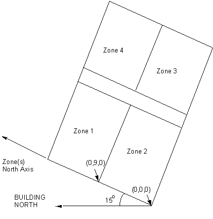
Figure 17. Illustration of Zone North Axis and Origins
Zone type is currently unused.
Zone Multiplier is designed as a “multiplier” for zone loads. It takes the calculated load for the inputted zone and multiplies it and sends the multiplied load to the attached system to meet the demand. The system will have to be specified to meet the entire multiplied zone load and will report the amount of the load it can meet in the Zone/Sys Sensible Heating or Cooling Energy/Rate report variable. The default is 1.
Zone ceiling height is used in several areas within EnergyPlus. Energyplus automatically calculates the zone ceiling height (m) from the average height of the zone. If this field is 0.0, negative or autocalculate, then the calculated zone ceiling height will be used in subsequent calculations. If this field is positive, then the calculated zone ceiling height will not be used -- the number entered here will be used as the zone ceiling height. If this number differs significantly from the calculated ceiling height, then a warning message will be issued. If a zone ceiling height is entered, but no Volume is entered, then the floor area (if there is one) times the zone ceiling height will be used as the volume.
Note that the Zone Ceiling Height is the distance from the Floor to the Ceiling in the Zone, not an absolute height from the ground.
Zone volume is used in several areas within EnergyPlus. EnergyPlus automatically calculates the zone volume (m3) from the zone geometry given by the surfaces that belong to the zone. If this field is 0.0, negative or autocalculate, then the calculated zone volume will be used in subsequent calculations. If this field is positive, then it will be used as the zone volume. If this number differs significantly from the calculated zone volume a warning message will be issued. For autocalculate to work properly, the zone must be enclosed by the entered walls. Note that indicating the volume to be calculated but entering a positive ceiling height in the previous field will cause the volume to be calculated as the floor area (if > 0) times the entered ceiling height; else the volume will be calculated from the described surfaces. If this field is positive, any ceiling height positive value will not be used in volume calculations.
Zone floor area is used in many places within EnergyPlus. EnergyPlus automatically calculates the zone floor area (m2) from the zone geometry given by the surfaces that belong to the zone. If this field is 0.0, negative or autocalculate, then the calculated zone floor area will be used in subsequent calculations. If this field is positive, then it will be used as the zone floor area. If this number differs significantly from the calculated zone floor area a warning message will be issued.
The Zone Inside Convection Algorithm field is optional. This field specifies the convection model to be used for the inside face of heat transfer surfaes associated with this zone. The choices are: Simple (constant natural convection - ASHRAE), Detailed (variable natural convection based on temperature difference - ASHRAE), CeilingDiffuser (ACH based forced and mixed convection correlations for ceiling diffuser configuration with simple natural convection limit), AdaptiveConvectionAlgorithm (complex arrangement of various models that adapt to various zone conditions and can be customized) and TrombeWall (variable natural convection in an enclosed rectangular cavity). See the Inside Convection Algorithm object for further descriptions of the available models.
If omitted or blank, the algorithm specified in the SurfaceConvectionAlgorithm:Inside object is the default.
The Zone Outside Convection Algorithm field is optional. This field specifies the convection model to be used for the outside face of heat transfer surfaces associated with this zone. The choices are: SimpleCombined, TARP, DOE-2, MoWiTT, and AdaptiveConvectionAlgorithm. The simple convection model applies heat transfer coefficients depending on the roughness and windspeed. This is a combined heat transfer coefficient that includes radiation to sky, ground, and air. The correlation is based on Figure 1, Page 25.1 (Thermal and Water Vapor Transmission Data), 2001 ASHRAE Handbook of Fundamentals.
The other convection models apply heat transfer coefficients depending on the roughness, windspeed, and terrain of the building’s location. These are convection only heat transfer coefficients; radiation heat transfer coefficients are calculated automatically by the program. The TARP algorithm was developed for the TARP software and combines natural and wind-driven convection correlations from laboratory measurements on flat plates. The DOE-2 and MoWiTT were derived from field measurements. The AdaptiveConvectionAlgorithm model is an dynamic algorithm that organizes a large number of different convection models and automatically selects the one that best applies. The adaptive convection algorithm can also be customized using the SurfaceConvectionAlgorithm:Outside:AdaptiveModelSelections input object. All algorithms are described more fully in the Engineering Reference.
If omitted or blank, the algorithm specified in the SurfaceConvectionAlgorithm:Outside object is the default.
This optional field defaults to Yes if not specified. The field is used to show when a zone is not part of the Total Floor Area as shown in the Annual Building Utility Performance Summary tables. Specifically, when No is specified, the area is excluded from both the conditioned floor area and the total floor area in the Building Area sub table and the Normalized Metrics sub tables.
And, an IDF example:
Zone,
DORM ROOMS AND COMMON AREAS, !- Name
0.0000000E+00, !- Direction of Relative North {deg}
0.0000000E+00, !- X Origin {m}
6.096000, !- Y Origin {m}
0.0000000E+00, !- Z Origin {m}
1, !- Type
1, !- Multiplier
autocalculate, !- Ceiling Height {m}
autocalculate; !- Volume {m3}
Each zone command produces zone outputs that echo the input fields above. However, the values to be used for the Zone Ceiling Height and Volume will be displayed if the entered fields are negative or zero. Details on this report are shown in the Output Details and Examples document.
In addition to the invariant outputs for the zone, atmospheric temperature and wind speed due to zone centroid heights are calculated. Rationale and further details on these values is shown in the Weather Station and Site Atmospheric Variation objects. These are described in the Group -- Location – Climate – Weather File Access.
Zone,Average,Zone Outdoor Dry Bulb [C]
Zone,Average,Zone Outdoor Wet Bulb [C]
Zone,Average,Zone Outdoor Wind Speed [m/s]
The outdoor air dry-bulb temperature calculated at the height above ground of the zone centroid.
The outdoor air wet-bulb temperature calculated at the height above ground of the zone centroid.
The outdoor wind speed calculated at the height above ground of the zone centroid.
In addition to the canned Surface reports (view the Reports section later in this document) and surface variables (above), the following variables are available for all zones:
Zone,Sum,Zone Total Internal Radiant Heat Gain [J]
Zone,Average,Zone Total Internal Radiant Heat Gain Rate [W]
Zone,Sum,Zone Total Internal Visible Heat Gain [J]
Zone,Average,Zone Total Internal Visible Heat Gain Rate [W]
Zone,Sum,Zone Total Internal Convective Heat Gain [J]
Zone,Average,Zone Total Internal Convective Heat Gain Rate [W]
Zone,Sum,Zone Total Internal Latent Gain [J]
Zone,Average,Zone Total Internal Latent Gain Rate [W]
Zone,Sum,Zone Total Internal Total Heat Gain [J]
Zone,Average,Zone Total Internal Total Heat Gain Rate [W]
Zone,Average,Zone Mean Air Temperature [C]
HVAC,Average,Zone/Sys Air Temperature[C]
Zone,Average,Zone Mean Radiant Temperature [C]
Zone,Average,Zone Operative Temperature [C]
HVAC,Average,Zone Air Balance Internal Convective Gains Rate [W]
HVAC,Average,Zone Air Balance Surface Convection Rate [W]
HVAC,Average,Zone Air Balance Interzone Air Transfer Rate [W]
HVAC,Average,Zone Air Balance Outdoor Air Transfer Rate [W]
HVAC,Average,Zone Air Balance System Air Transfer Rate [W]
HVAC,Average,Zone Air Balance Air Energy Storage Rate [W]
HVAC,Average,Zone Air Balance Deviation Rate [W]
HVAC,Sum,Zone/Sys Sensible Heating Energy[J]
HVAC,Sum,Zone/Sys Sensible Cooling Energy[J]
HVAC,Average,Zone/Sys Sensible Heating Rate[W]
HVAC,Average,Zone/Sys Sensible Cooling Rate[W]
HVAC,Average,Zone Air Humidity Ratio[]
HVAC,Average,Zone Air Relative Humidity[%]
Two of these are of particular interest:
Zone,Average,Zone Mean Air Temperature [C]
HVAC,Average,Zone/Sys Air Temperature [C]
These two variable outputs are/should be identical. However, note that they can be reported at different time intervals. “Zone Mean Air Temperature” is only available on the Zone/HB timestep (Number of Timesteps per Hour) whereas “Zone/Sys Air Temperature” can be reported at the HVAC timestep (which can vary).
From the code definition, the zone mean air temperature is the average temperature of the air temperatures at the system timestep. Remember that the zone heat balance represents a “well stirred” model for a zone, therefore there is only one mean air temperature to represent the air temperature for the zone.
This is very similar to the mean air temperature in the last field. The “well stirred” model for the zone is the basis, but this temperature is also available at the “detailed” system timestep.
At writing of this document, trying to determine what this is.
The Mean Radiant Temperature (MRT) in degrees Celsius of a space is a measure of the combined effects of temperatures of surfaces within that space. Specifically it is the surface area × emissivity weighted average of the zone inside surface temperatures (ref. Surface Inside Temperature), where emissivity is the Thermal Absorptance of the inside material layer of each surface.
Zone Operative Temperature (OT) is the average of the Zone Mean Air Temperature (MAT) and Zone Mean Radiant Temperature (MRT), OT = 0.5*MAT + 0.5*MRT. This report variable is not affected by the type of thermostat controls in the zone, and does not include the direct effect of high temperature radiant systems. See also Zone Thermostat Operative Temperature.
The Zone Air Balance Internal Convective Gains Rate is the sum, in watts, of heat transferred to the zone air from all types of internal gains, including people, lights, equipment etc. This and the following provide results on the load components of the zone air heat balance. This field is not multiplied by zone or group multipliers.
The Zone Air Balance Surface Convection Rate is the sum, in watts, of heat transferred to the zone air from all the surfaces. This field is not multiplied by zone or group multipliers.
The Zone Air Balance Interzone Air Transfer Rate is the sum, in watts, of heat transferred to the zone air from all the transfers of air from other thermal zones. This field is not multiplied by zone or group multipliers.
The Zone Air Balance Outdoor Air Transfer Rate is the sum, in watts, of heat transferred to the zone air from all the transfers of air from the out side, such as infiltration. This field is not multiplied by zone or group multipliers.
The Zone Air Balance System Air Transfer Rate is the sum, in watts, of heat transferred to the zone air by HVAC air systems. This field is not multiplied by zone or group multipliers.
The Zone Air Balance Air Energy Storage Rate is the heat stored, in watts, in the zone air as result of zone air temperature changing from one timestep to the next. This field is not multiplied by zone or group multipliers.
The Zone Air Balance Deviation Rate is the imbalance, in watts, in the energy balance for zone air. The value should be near zero but will become non-zero if zone conditions are changing rapidly or erratically. This field is not multiplied by zone or group multipliers. (This report variable is only generated if the user has set a computer system environment variable DisplayAdvancedReportVariables equal to “yes”.)
This report variable represents the sensible heating energy in Joules that is actually supplied by the system to that zone for the timestep reported. This is the sensible heating rate multiplied by the simulation timestep. This is calculated and reported from the Correct step in the Zone Predictor-Corrector module. . This field is not multiplied by zone or group multipliers.
Zone/Sys Sensible Heating (and Cooling) Energy (and Rate) all report the heating or cooling delivered by the HVAC system to a zone. These values are calculated by multiplying the supply air mass flow rate by the difference between the supply air temperature and the zone air temperature. This does not always indicate the operation of heating or cooling coils. For example, cooling will be reported if the supply air is cooled due to the introduction of outside air, even if all coils are off.
Note that these variables are calculated at the system timestep. When reported at the "detailed" reporting frequency, these variable will never show heating and cooling both in the same system timestep. If reported at a frequency less than "Detailed" (for example, Hourly) values may appear in both the heating and cooling variable for the same hour if the system cooled the zone for part of the reporting period and heated the zone for another part of the reporting period.
This report variable represents the sensible cooling energy in Joules that is actually supplied by the system to that zone for the timestep reported. This is the sensible cooling rate multiplied by the simulation timestep. This is calculated and reported from the Correct step in the Zone Predictor-Corrector module. This field is not multiplied by zone or group multipliers.
This report variable represents the sensible heating rate in Watts that is actually supplied by the system to that zone for the timestep reported. This is calculated and reported from the Correct step in the Zone Predictor-Corrector module. This field is not multiplied by zone or group multipliers.
This report variable represents the sensible cooling rate in Watts that is actually supplied by the system to that zone for the timestep reported. This is calculated and reported from the Correct step in the Zone Predictor-Corrector module. This field is not multiplied by zone or group multipliers.
This report variable represents the air humidity ratio after the correct step for each zone. The humidity ratio is the mass of water vapor to the mass of dry air contained in the zone in (kg water/kg air) and is unitless.
This report variable represents the air relative humidity after the correct step for each zone. The relative humidity is in percent and uses the Zone Air Temperature, the Zone Air Humidity Ratio and the Outside Barometric Pressure for calculation.
These report variables represent the sum of radiant gains from specific internal sources (e.g. equipment) throughout the zone in Watts (for rate) or joules. This includes radiant gain from People, Lights, Electric Equipment, Gas Equipment, Other Equipment, Hot Water Equipment, and Steam Equipment.
These report variables expresse the sum of heat gain in Watts (for rate) or joules that is the calculated short wavelength radiation gain from lights in the zones. This calculation uses the total energy from lights and the fraction visible to realize this value, summed over the zones in the simulation.
These report variables represent the sum of convective gains from specific sources (e.g. equipment) throughout the zone in Watts (for rate) or joules. This includes convective gain from People, Lights, Electric Equipment, Gas Equipment, Other Equipment, Hot Water Equipment, and Steam Equipment.
These report variables represent the sum of latent gains from specific internal sources (e.g. equipment) throughout the zone in Watts (for rate) or joules. This includes latent gain from People, Electric Equipment, Gas Equipment, Other Equipment, Hot Water Equipment, and Steam Equipment.
These report variables represent the sum of all heat gains throughout the zone in Watts (for rate) or joules. This includes all heat gains from People, Lights, Electric Equipment, Gas Equipment, Other Equipment, Hot Water Equipment, and Steam Equipment.
The ZoneList object defines a list of Zone objects. It is primarily used with the ZoneGroup object to provide a generalized way for doing "Floor Multipliers". (See the ZoneGroup description below.) The associated ZoneList output variables also provide a way to aggregate and organize zone loads.
Zone lists are not exclusive. A zone can be referenced be more than one ZoneList object.
The name of the ZoneList object. Must be unique across ZoneLists.
Reference to a Zone object. This field is extensible; for greater than 20 zones, edit the IDD to add more Zone Name fields.
ZoneList,
Mid Floor List, !- Name
Mid West Zone, !- Zone 1 Name
Mid Center Zone, !- Zone 2 Name
Mid East Zone; !- Zone 3 Name
The following output variables are reported by the ZoneList object:
HVAC,Average,Zone List Sensible Heating Rate[W]
HVAC,Average,Zone List Sensible Cooling Rate[W]
HVAC,Sum,Zone List Sensible Heating Energy[J]
HVAC,Sum,Zone List Sensible Cooling Energy[J]
All ZoneList variables are the sum of the corresponding Zone variables. Zone Multiplier fields in the Zone objects are also taken into account.
The ZoneGroup object adds a multiplier to a ZoneList. This can be used to reduce the amount of input necessary for simulating repetitive structures, such as the identical floors of a multi-story building. To create a "Floor Multiplier", use the ZoneList object to organize several zones into a typical floor. Then use the Zone List Multiplier field in the ZoneGroup object to multiply the system load for the zones in the list will also be multiplied. Zones with a Multiplier field greater than one in the Zone object are effectively double-multiplied.
NOTE: Although ZoneLists are not exclusive by themselves, ZoneLists used to form a ZoneGroup are exclusive; the ZoneLists used with a ZoneGroup must not have any zones in common.
n For floors that are multiplied, connect exterior boundary conditions of the floor to the ceiling and vice versa.
n Since exterior convection coefficients vary with elevation, locate the typical middle floor zones midheight between the lowest and highest middle floors to be modeled.
n Shading must be identical for all multiplied floors or less accurate results may be obtained by using the zone list multiplier.
ZoneGroup and ZoneList can also be used to simulate other repetitive cases, such as clusters of zones on the ground.
The name of the ZoneGroup object. This must be unique across ZoneGroups.
Reference to a ZoneList object. The zones in the list constitute the zones in the group.
An integer multiplier.
ZONE GROUP,
Mid Floor, !- Zone Group Name
Mid Floor List, !- Zone List Name
8; !- Zone List Multiplier
The following output variables are reported by the ZoneGroup object:
HVAC,Average,Zone Group Sensible Heating Rate[W]
HVAC,Average,Zone Group Sensible Cooling Rate[W]
HVAC,Sum,Zone Group Sensible Heating Energy[J]
HVAC,Sum,Zone Group Sensible Cooling Energy[J]
All ZoneGroup variables report the associated ZoneList value multiplied by the Zone List Multiplier.
What’s a building without surfaces?
EnergyPlus allows for several surface types:
n BuildingSurface:Detailed
n FenestrationSurface:Detailed
n Shading:Site:Detailed
n Shading:Building:Detailed
n Shading:Zone:Detailed
Each of the preceding surfaces has “correct” geometry specifications. BuildingSurface and Fenestration surfaces (heat transfer surfaces) are used to describe the important elements of the building (walls, roofs, floors, windows, doors) that will determine the interactions of the building surfaces with the outside environment parameters and the internal space requirements. These surfaces are also used to represent “interzone” heat transfer. During specification of surfaces, several “outside” environments may be chosen:
n Ground – when the surface is in touch with the ground (e.g. slab floors)
n Outdoors – when the surface is an external surface (e.g. walls, roofs, windows directly exposed to the outdoor conditions)
n Surface – when the surface is
n An adiabatic internal zone surface
n A interzone surface
n Zone – when the surface is
n A interzone surface in which the other surface is not put in the input file.
n OtherSideCoefficients – when using a custom profile to describe the external conditions of the surface (advanced concept – covered in subject: SurfaceProperty:OtherSideCoefficients)
n OtherSideConditionsModel – when using specially modeled components, such as active solar systems, that cover the outside surface and modify the conditions it experiences.
Surface items must also specify an “outside face object”. This is
n Current surface name – for adiabatic internal surfaces.
n A surface name in another zone – for interzone heat transfer.
n An “opposing” surface name (in the current zone) – for representing “middle” zones.
Zone items must also specify an “outside face object”. This is
n The zone that contains the other surface that is adjactent to this surface but is not entered in input.
Note that heat transfer surfaces are fully represented with each description. As stated earlier in the Construction description, materials in the construction (outside to inside) are included but film coeffients neither inside nor outside are used in the description – these are automatically calculated during the EnergyPlus run. Interzone surfaces which do not have a symmetrical construction (such as a ceiling/floor) require two Construction objects with the layers in reverse order. For example, CEILING with carpet, concrete, ceiling tile and FLOOR with ceiling tile, concrete, carpet. If interzone surfaces have a symmetrical construction, the specification for the two surfaces can reference the same Construction.
Shading surfaces are used to describe aspects of the site which do not directly impact the physical interactions of the environmental parameters but may significantly shade the building during specific hours of the day or time so the year (e.g. trees, bushes, mountains, nearby buildings which aren’t being simulated as part of this facility, etc.)
Note that surfaces which are part of the simulated building automatically shade other parts of the building as geometry and time of day dictate – there is no need on the user’s part to include surfaces that might be in other zones for shading.
Another surface type:
n InternalMass
is used to specify the construction/material parameters and area of items within the space that are important to heat transfer calculations but not necessarily important geometrically. (For example, furniture within the space – particularly for large spaces). Internal mass can also be used for internal walls that are not needed (when FullInteriorAndExterior Solar Distribution is in effect) for solar distribution or to represent many, if not all, interior walls when solar is distributed to the floors only.
EnergyPlus can quite accurately simulate the surface heat exchange between two zones. However, this accuracy is not always required and using interzonal heat transfer does add to the complexity of the calculations – thus requiring more CPU time to simulate. More information about interzonal heat transfer calculations is contained in the Engineering Reference. Some simple guidelines are presented here – for three cases: adiabatic surfaces, surfaces in “middle” zones, and surfaces where heat transfer is “expected” (e.g. between a residence and an unheated, attached garage).
n Adiabatic Surfaces – These surfaces would be represented as common surfaces (between two zones) where both zones are typically the same temperature. Thus, no transfer is expected in the surface from one zone to the next. These surfaces should be described as simply internal surfaces for the zone referencing as their Outside Boundary Condition Object (see later description in individual surface objects) their own surface names.
n Surfaces in Middle Zones – Middle zones in a building can be simulated using a judicious use of surfaces and zone multipliers to effect the correct “loads” for the building. Thus, middle zone behavior can be simulated without modeling the adjacent zones. This is done by specifying a surface within the zone. For example, a middle floor zone can be modeled by making the floor the Outside Boundary Condition Object for the ceiling, and the ceiling the Outside Boundary Condition Object for the floor.
n Surfaces between Zones with differing temperatures – These zones represent the true use of interzone surfaces. In a residence that has an attached garage, the garage may be unheated/uncooled or at least not conditioned to the same degree as the residence interior. In this case, EnergyPlus can be used to accurately calculate the effects of the differently conditioned space to the other spaces.
EnergyPlus uses an area weighted approximation to calculate "view factors" between surfaces within a thermal zone. Each surface uses the total area that it can “see” among the other surfaces. The approximate view factor from this surface to each other surface is then the area of the receiving surface over the sum of areas that is visible to the sending surface.
In order to account in some limited way for the fact that certain surfaces will not see each other, several assumptions have been built into this simple view factor approximation. First, a surface cannot see itself. Second, surfaces with approximately the same azimuth (facing direction) and tilt ("same" being within a built in limit) will not see each other. This means that a window will not see the wall that it is placed on, for example. Third, floors cannot see each other. Fourth, if the surface is a floor, ceiling, roof, or internal mass, the rule for the same azimuth and tilt eliminating radiant exchange between surface is waived when the receiving surface is floor, roof, ceiling, or internal mass as long as both surfaces are not floors.
Note that this does not take into account that surfaces may be "around the corner" from each other and in reality not see each other at all. Rooms are assumed to be convex rather than concave in this method.
To summarize, using the Surface “Class”, the approximate view factors have:
1. No surface sees itself.
2. No Floor sees another floor.
3. All other surface types see Internal Mass.
4. All other surface types see floors.
5. Floors always see ceilings.
6. Floors always see roofs.
7. All other surfaces whose tilt or facing angle differences are greater than 10 degrees see each other.
If geometry is correct, conditions 1,3, and 7 should take care of all surfaces, but the other conditions supply common sense when the geometry is incorrect. More information about the EnergyPlus view factor calculation is contained in the Engineering Reference document.
Before the surface objects are explained in detail, a description of geometric parameters used in EnergyPlus will be given. Since the input of surface vertices is common to most of the surface types, it will also be given a separate discussion.
Some flexibility is allowed in specifying surface vertices. This flexibility is embodied in the GlobalGeometryRules class/object in the input file. Note that the parameters specified in this statement are used for all surface vertice inputs – there is no further “flexibility” allowed.
In order to perform shadowing calculations, the building surfaces must be specified. EnergyPlus uses a three dimensional (3D) Cartesian coordinate system for surface vertex specification. This Right Hand coordinate system has the X-axis pointing east, the Y-axis pointing north, and the Z-axis pointing up. See figure below.
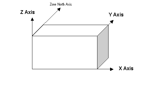
Figure 18. EnergyPlus Coordinate System
The shadowing algorithms in EnergyPlus rely on surfaces having vertices in a certain order and positional structure. Thus, the surface translator needs to know the starting point for each surface entry. The choices are: UpperLeftCorner, LowerLeftCorner , UpperRightCorner, or LowerRightCorner. Since most surfaces will be 4 sided, the convention will specify this position as though each surface were 4 sided. Extrapolate 3 sided figures to this convention. For 5 and more sided figures, again, try to extrapolate the best “corner” starting position.
Surfaces are always specified as being viewed from the outside of the zone to which they belong. (Shading surfaces are specified slightly differently and are discussed under the particular types). EnergyPlus needs to know whether the surfaces are being specified in counterclockwise or clockwise order (from the Starting Vertex Position). EnergyPlus uses this to determine the outward facing normal for the surface (which is the facing angle of the surface – very important in shading and shadowing calculations.
Vertices can be specified in two ways: using “Absolute”/“World” coordinates, or a relative coordinate specification. Relative coordinates allow flexibility of rapid change to observe changes in building results due to orientation and position. “World” coordinates will facilitate use within a CADD system structure.
Relative coordinates make use of both Building and Zone North Axis values as well as Zone Origin values to locate the surface in 3D coordinate space. World coordinates do not use these values.
Typically, all zone origin values for “World” coordinates will be (0,0,0) but Building and Zone North Axis values may be used in certain instances (namely the Daylighting Coordinate Location entries).
Daylighting reference points need to be specified as well. Again, there can be two flavors; relative and world. Daylighting reference points must fit within the zone boundaries.
Relative coordinates make use of both Building and Zone North Axis values as well as Zone Origin values to locate the reference point in 3D coordinate space. World coordinates do not use these values.
Simple, rectangular surfaces (Wall:Exterior, Wall:Adiabatic, Wall:Underground, Wall:Interzone, Roof, Ceiling:Adiabatic, Ceiling:Interzone, Floor:GroundContact, Floor:Adiabatic, Floor:Interzone) can be specified with their Lower Left Corner as relative or world.
Relative (default) corners are specified relative to the Zone Origin for each surface. World corners would specify the absolute/world coordinate for this corner.
Surfaces make up the buildings and the elements that shade buildings. There are several methods to inputting surfaces, ranging from simple rectangular surfaces to detailed descriptions that describe each vertex in the order specified in the GlobalGeometryRules object. The simple, rectangular surface objects are described first with the more detailed descriptions following.
Walls are usually vertical (tilt = 90 degrees). These objects are used to describe exterior walls, interior walls (adiabatic), underground walls, and walls adjacent to other zones.
The Wall:Exterior object is used to describe walls that are exposed to the external environment. They receive sun, wind – all the characteristics of the external world.
This is a unique name associated with the exterior wall. It is used in several other places as a reference (e.g. as the base surface name for a Window or Door).
This is the name of the construction (ref: Construction) used in the surface. Regardless of location in the building, the “full” construction (all layers) is used. For example, for an interior wall separating two zones, zone x would have the outside layer (e.g. drywall) as the material that shows in zone y and then the layers to the inside layer – the material that shows in zone x. For symmetric constructions, the same construction can be used in the surfaces described in both zones.
This is the zone name to which the surface belongs.
The Azimuth Angle indicates the direction that the wall faces (outward normal). The angle is specified in degrees where East=90, South=180, West=270, North=0.
The tilt angle is the angle (in degrees) that the wall is tilted from horizontal (or the ground). Normally, walls are tilted 90 degrees and that is the default for this field.
The rectangular surfaces specify the lower left corner of the surface for their starting coordinate. This is specified with (x,y,z) and can be relative to the zone origin or in world coordinates, depending on the value for rectangular surfaces specified in the GlobalGeometryRules object.
This field is the X coordinate (in meters).
This field is the Y coordinate (in meters).
This field is the Z coordinate (in meters).
This field is the length of the wall in meters.
This field is the height of the wall in meters.
The Wall:Adiabatic object is used to describe interior walls and partitions. Adiabatic walls are used to describe walls next to zones that have the same thermal conditions (thus, no heat transfer).
This is a unique name associated with the interior wall. It is used in several other places as a reference (e.g. as the base surface name for a Window or Door).
This is the name of the construction (ref: Construction) used in the surface. Regardless of location in the building, the “full” construction (all layers) is used. For example, for an interior wall separating two zones, zone x would have the outside layer (e.g. drywall) as the material that shows in zone y and then the layers to the inside layer – the material that shows in zone x. For symmetric constructions, the same construction can be used in the surfaces described in both zones.
This is the zone name to which the surface belongs.
The Azimuth Angle indicates the direction that the wall faces (outward normal). The angle is specified in degrees where East=90, South=180, West=270, North=0.
The tilt angle is the angle (in degrees) that the wall is tilted from horizontal (or the ground). Normally, walls are tilted 90 degrees and that is the default for this field.
The rectangular surfaces specify the lower left corner of the surface for their starting coordinate. This is specified with (x,y,z) and can be relative to the zone origin or in world coordinates, depending on the value for rectangular surfaces specified in the GlobalGeometryRules object.
This field is the X coordinate (in meters).
This field is the Y coordinate (in meters).
This field is the Z coordinate (in meters).
This field is the length of the wall in meters.
This field is the height of the wall in meters.
The Wall:Underground object is used to describe walls with ground contact. The temperature at the outside of the wall is the temperature in the GroundTemperature:BuildingSurface object.
This is a unique name associated with the underground wall. It is used in several other places as a reference (e.g. as the base surface name for a Window or Door).
This is the name of the construction (ref: Construction) used in the surface. Regardless of location in the building, the “full” construction (all layers) is used. For example, for an interior wall separating two zones, zone x would have the outside layer (e.g. drywall) as the material that shows in zone y and then the layers to the inside layer – the material that shows in zone x. For symmetric constructions, the same construction can be used in the surfaces described in both zones. Note that if the construction is Construction:CfactorUndergroundWall then the GroundFCfactoreMethod will be used for this wall.
This is the zone name to which the surface belongs.
The Azimuth Angle indicates the direction that the wall faces (outward normal). The angle is specified in degrees where East=90, South=180, West=270, North=0.
The tilt angle is the angle (in degrees) that the wall is tilted from horizontal (or the ground). Normally, walls are tilted 90 degrees and that is the default for this field.
The rectangular surfaces specify the lower left corner of the surface for their starting coordinate. This is specified with (x,y,z) and can be relative to the zone origin or in world coordinates, depending on the value for rectangular surfaces specified in the GlobalGeometryRules object.
This field is the X coordinate (in meters).
This field is the Y coordinate (in meters).
This field is the Z coordinate (in meters).
This field is the length of the wall in meters.
This field is the height of the wall in meters.
The Wall:Interzone object is used to describe walls adjacent to zones that are significantly different conditions than the zone with this wall.
This is a unique name associated with the interzone wall. It is used in several other places as a reference (e.g. as the base surface name for a Window or Door).
This is the name of the construction (ref: Construction) used in the surface. Regardless of location in the building, the “full” construction (all layers) is used. For example, for an interior wall separating two zones, zone x would have the outside layer (e.g. drywall) as the material that shows in zone y and then the layers to the inside layer – the material that shows in zone x. For symmetric constructions, the same construction can be used in the surfaces described in both zones.
This is the zone name to which the surface belongs.
The Outside Boundary Condition Object field is the name of a wall in an adjacent zone or the name of the adjacent zone. If the adjacent zone option is used, the adjacent wall is automatically generated in the adjacent zone. If the surface name is used, it must be in the adjacent zone.
The Azimuth Angle indicates the direction that the wall faces (outward normal). The angle is specified in degrees where East=90, South=180, West=270, North=0.
The tilt angle is the angle (in degrees) that the wall is tilted from horizontal (or the ground). Normally, walls are tilted 90 degrees and that is the default for this field.
The rectangular surfaces specify the lower left corner of the surface for their starting coordinate. This is specified with (x,y,z) and can be relative to the zone origin or in world coordinates, depending on the value for rectangular surfaces specified in the GlobalGeometryRules object.
This field is the X coordinate (in meters).
This field is the Y coordinate (in meters).
This field is the Z coordinate (in meters).
This field is the length of the wall in meters.
This field is the height of the wall in meters.
Roofs and ceilings are, by default, flat (tilt = 0 degrees). These objects are used to describe roofs, interior ceilings (adiabatic) and ceilings adjacent to other zones.
The Roof object is used to describe roofs that are exposed to the external environment.
This is a unique name associated with the roof. It is used in several other places as a reference (e.g. as the base surface name for a Window or Door).
This is the name of the construction (ref: Construction) used in the surface. Regardless of location in the building, the “full” construction (all layers) is used. For example, for an interior wall separating two zones, zone x would have the outside layer (e.g. drywall) as the material that shows in zone y and then the layers to the inside layer – the material that shows in zone x. For symmetric constructions, the same construction can be used in the surfaces described in both zones.
This is the zone name to which the surface belongs.
The Azimuth Angle indicates the direction of the outward normal for the roof. The angle is specified in degrees where East=90, South=180, West=270, North=0.
The tilt angle is the angle (in degrees) that the wall is tilted from horizontal (or the ground). Flat roofs are tilted 0 degrees and that is the default for this field.
The rectangular surfaces specify the lower left corner of the surface for their starting coordinate. This is specified with (x,y,z) and can be relative to the zone origin or in world coordinates, depending on the value for rectangular surfaces specified in the GlobalGeometryRules object.
This field is the X coordinate (in meters).
This field is the Y coordinate (in meters).
This field is the Z coordinate (in meters).
This field is the length of the roof in meters.
This field is the width of the roof in meters.
The Ceiling:Adiabatic object is used to describe interior ceilings that separate zones of like conditions.
This is a unique name associated with the ceiling. It is used in several other places as a reference (e.g. as the base surface name for a Window or Door).
This is the name of the construction (ref: Construction) used in the surface. Regardless of location in the building, the “full” construction (all layers) is used. For example, for an interior wall separating two zones, zone x would have the outside layer (e.g. drywall) as the material that shows in zone y and then the layers to the inside layer – the material that shows in zone x. For symmetric constructions, the same construction can be used in the surfaces described in both zones.
This is the zone name to which the surface belongs.
The Azimuth Angle indicates the direction of the outward normal for the roof. The angle is specified in degrees where East=90, South=180, West=270, North=0.
The tilt angle is the angle (in degrees) that the wall is tilted from horizontal (or the ground). Flat ceilings are tilted 0 degrees and that is the default for this field.
The rectangular surfaces specify the lower left corner of the surface for their starting coordinate. This is specified with (x,y,z) and can be relative to the zone origin or in world coordinates, depending on the value for rectangular surfaces specified in the GlobalGeometryRules object.
This field is the X coordinate (in meters).
This field is the Y coordinate (in meters).
This field is the Z coordinate (in meters).
This field is the length of the ceiling in meters.
This field is the width of the ceiling in meters.
The Ceiling:Interzone object is used to describe interior ceilings that separate zones of differing conditions (and expect heat transfer through the ceiling from the adjacent zone).
This is a unique name associated with the interzone ceiling. It is used in several other places as a reference (e.g. as the base surface name for a Window or Door).
This is the name of the construction (ref: Construction) used in the surface. Regardless of location in the building, the “full” construction (all layers) is used. For example, for an interior wall separating two zones, zone x would have the outside layer (e.g. drywall) as the material that shows in zone y and then the layers to the inside layer – the material that shows in zone x. For symmetric constructions, the same construction can be used in the surfaces described in both zones.
This is the zone name to which the surface belongs.
The Outside Boundary Condition Object field is the name of a floor in an adjacent zone or the name of the adjacent zone. If the adjacent zone option is used, the adjacent floor is automatically generated in the adjacent zone. If the surface name is used, it must be in the adjacent zone.
The Azimuth Angle indicates the direction of the outward normal for the roof. The angle is specified in degrees where East=90, South=180, West=270, North=0.
The tilt angle is the angle (in degrees) that the wall is tilted from horizontal (or the ground). Flat ceilings are tilted 0 degrees and that is the default for this field.
The rectangular surfaces specify the lower left corner of the surface for their starting coordinate. This is specified with (x,y,z) and can be relative to the zone origin or in world coordinates, depending on the value for rectangular surfaces specified in the GlobalGeometryRules object.
This field is the X coordinate (in meters).
This field is the Y coordinate (in meters).
This field is the Z coordinate (in meters).
This field is the length of the ceiling in meters.
This field is the width of the ceiling in meters.
Floors are, by default, flat (tilt = 180 degrees). These objects are used to describe floors on the ground, interior floors (adiabatic) and floors adjacent to other zones.
The Floor:GroundContact object is used to describe floors that have ground contact (usually called slabs). The temperature at the outside of the floor is the temperature in the GroundTemperature:BuildingSurface object.
This is a unique name associated with the floor.
This is the name of the construction (ref: Construction) used in the surface. Regardless of location in the building, the “full” construction (all layers) is used. For example, for an interior wall separating two zones, zone x would have the outside layer (e.g. drywall) as the material that shows in zone y and then the layers to the inside layer – the material that shows in zone x. For symmetric constructions, the same construction can be used in the surfaces described in both zones. Note that if the construction is Construction:FfactorGroundFloor, then the GroundFCfactorMethod will be used with this floor.
This is the zone name to which the surface belongs.
The Azimuth Angle indicates the direction of the outward normal for the roof. The angle is specified in degrees where East=90, South=180, West=270, North=0.
The tilt angle is the angle (in degrees) that the wall is tilted from horizontal (or the ground). Flat floors are tilted 180 degrees and that is the default for this field.
The rectangular surfaces specify the lower left corner of the surface for their starting coordinate. This is specified with (x,y,z) and can be relative to the zone origin or in world coordinates, depending on the value for rectangular surfaces specified in the GlobalGeometryRules object.
This field is the X coordinate (in meters).
This field is the Y coordinate (in meters).
This field is the Z coordinate (in meters).
This field is the length of the floor in meters.
This field is the width of the floor in meters.
The Floor:Adiabatict object is used to describe interior floors or floors that you wish to model with no heat transfer from the exterior to the floor.
This is a unique name associated with the floor.
This is the name of the construction (ref: Construction) used in the surface. Regardless of location in the building, the “full” construction (all layers) is used. For example, for an interior wall separating two zones, zone x would have the outside layer (e.g. drywall) as the material that shows in zone y and then the layers to the inside layer – the material that shows in zone x. For symmetric constructions, the same construction can be used in the surfaces described in both zones.
This is the zone name to which the surface belongs.
The Azimuth Angle indicates the direction of the outward normal for the roof. The angle is specified in degrees where East=90, South=180, West=270, North=0.
The tilt angle is the angle (in degrees) that the wall is tilted from horizontal (or the ground). Flat floors are tilted 180 degrees and that is the default for this field.
The rectangular surfaces specify the lower left corner of the surface for their starting coordinate. This is specified with (x,y,z) and can be relative to the zone origin or in world coordinates, depending on the value for rectangular surfaces specified in the GlobalGeometryRules object.
This field is the X coordinate (in meters).
This field is the Y coordinate (in meters).
This field is the Z coordinate (in meters).
This field is the length of the floor in meters.
This field is the width of the floor in meters.
The Floor:Interzone object is used to describe floors that are adjacent to other zones that have differing conditions and you wish to model the heat transfer through the floor.
This is a unique name associated with the floor.
This is the name of the construction (ref: Construction) used in the surface. Regardless of location in the building, the “full” construction (all layers) is used. For example, for an interior wall separating two zones, zone x would have the outside layer (e.g. drywall) as the material that shows in zone y and then the layers to the inside layer – the material that shows in zone x. For symmetric constructions, the same construction can be used in the surfaces described in both zones.
This is the zone name to which the surface belongs.
The Outside Boundary Condition Object field is the name of a ceiling in an adjacent zone or the name of the adjacent zone. If the adjacent zone option is used, the adjacent ceiling is automatically generated in the adjacent zone. If the surface name is used, it must be in the adjacent zone.
The Azimuth Angle indicates the direction of the outward normal for the roof. The angle is specified in degrees where East=90, South=180, West=270, North=0.
The tilt angle is the angle (in degrees) that the wall is tilted from horizontal (or the ground). Flat floors are tilted 180 degrees and that is the default for this field.
The rectangular surfaces specify the lower left corner of the surface for their starting coordinate. This is specified with (x,y,z) and can be relative to the zone origin or in world coordinates, depending on the value for rectangular surfaces specified in the GlobalGeometryRules object.
This field is the X coordinate (in meters).
This field is the Y coordinate (in meters).
This field is the Z coordinate (in meters).
This field is the length of the floor in meters.
This field is the width of the floor in meters.
The following window and door objects can be used to specify simple, rectangular doors and windows. In each case, the lower left corner (locator coordinate) of the window or door is specified relative to the surface it is on. Viewing the base surface as a planar surface, base the relative location from the lower left corner of the base surface. Vertex entry description as well as provisions for a few other surface types can be entered with the FenestrationSurface:Detailed object.
The Window object is used to place windows on surfaces that can have windows, including exterior walls, interior walls, interzone walls, roofs, floors that are exposed to outdoor conditions, interzone ceiling/floors. These, of course, can be entered using the simple rectangular objects or the more detailed vertex entry objects.
This is a unique name associated with the window.
This is the name of the subsurface’s construction (ref: Construction and Construction:WindowDataFile).
For windows, if Construction Name is not found among the constructions on the input (.idf) file, the Window5 Data File (default Window5DataFile.dat) will be searched for that Construction Name (see “Importing Windows from WINDOW 5”). If that file is not present or if the Construction Name does not match the name of an entry on the file, an error will result. If there is a match, a window construction and its corresponding glass and gas materials will be created from the information read from the file.
This is the name of a surface that contains this subsurface. Certain kinds of surfaces may not be allowed to have subsurfaces. For example, a surface in contact with the ground (e.g., Outside Boundary Condition = Ground) cannot contain a window. The window assumes the outward facing angle as well as the tilt angle of the base surface.
This field, if not blank, is the name of the window shading control (ref: WindowProperty:ShadingControl) for this subsurface. It is used for Surface Type = Window and GlassDoor. To assign a shade to a window or glass door, see WindowMaterial: Shade. To assign a screen, see WindowMaterial:Screen. To assign a blind, see WindowMaterial:Blind. To assign switchable glazing, such as electrochromic glazing, see WindowProperty:ShadingControl.
This field, if not blank, can be used to specify window frame, divider and reveal-surface data (ref: WindowProperty:FrameAndDivider). It is used only for exterior GlassDoors and rectangular exterior Windows, i.e., those with OutsideFaceEnvironment = Outdoors.
This field should be blank for triangular windows.
This field is the number of identical items on the base surface. Using Multiplier can save input effort and calculation time. In the calculation the area (and area of frame and divider, if present and surface type is a window) is multiplied by Multiplier. The calculation of shadowing on the subsurfaces (and the calculation of the interior distribution of beam solar radiation transmitted by windows and glass doors) are done for the specified subsurface position and dimensions.
Multiplier should be used with caution. Multiplier > 1 can give inaccurate or nonsensical results in situations where the results are sensitive to window or glass door position. This includes shadowing on the window/glass door, daylighting from the window/glass door, and interior distribution of solar radiation from the window/glass door. In these cases, the results for the single input window/glass door, after multiplication, may not be representative of the results you would get if you entered each of the multiple subsurfaces separately.
If Multiplier > 1, you will get
--a warning if Solar Distribution = FullExterior or FullInteriorAndExterior (ref: Building - Field: Solar Distribution), indicating that the shadowing on the input window or the interior solar radiation distribution from the input window may not be representative of the actual group of windows. No warning is issued if Solar Distribution = MinimalShadowing.
--an error if the window is an exterior window/glass door in a zone that has a detailed daylighting calculation (Daylighting:Detailed specified for the zone). Since a single window with a multiplier can never give the same daylight illuminance as the actual set of windows, you are not allowed to use Multiplier in this situation.
The rectangular subsurfaces specify the lower left corner of the surface for their starting coordinate. This corner is specifed relative to the lower left corner of the base surface by specifying the X and Z values from that corner.
This field is the X coordinate (in meters).
This field is the Z coordinate (in meters).
This field is the length of the window in meters.
This field is the height of the window in meters.
The Door object is used to place opaque doors on surfaces that can have doors, including exterior walls, interior walls, interzone walls, roofs, floors that are exposed to outdoor conditions, interzone ceiling/floors. These, of course, can be entered using the simple rectangular objects or the more detailed vertex entry objects.
This is a unique name associated with the door.
This is the name of the subsurface’s construction (ref: Construction)
This is the name of a surface that contains this subsurface. Certain kinds of surfaces may not be allowed to have subsurfaces. The door assumes the outward facing angle as well as the tilt angle of the base surface.
This field is the number of identical items on the base surface. Using Multiplier can save input effort and calculation time. In the calculation the area (and area of frame and divider, if present and surface type is a window) is multiplied by Multiplier. The calculation of shadowing on the subsurfaces (and the calculation of the interior distribution of beam solar radiation transmitted by windows and glass doors) are done for the specified subsurface position and dimensions.
Multiplier should be used with caution. Multiplier > 1 can give inaccurate or nonsensical results in situations where the results are sensitive to window or glass door position. This includes shadowing on the window/glass door, daylighting from the window/glass door, and interior distribution of solar radiation from the window/glass door. In these cases, the results for the single input window/glass door, after multiplication, may not be representative of the results you would get if you entered each of the multiple subsurfaces separately.
If Multiplier > 1, you will get
--a warning if Solar Distribution = FullExterior or FullInteriorAndExterior (ref: Building - Field: Solar Distribution), indicating that the shadowing on the input window or the interior solar radiation distribution from the input window may not be representative of the actual group of windows. No warning is issued if Solar Distribution = MinimalShadowing.
--an error if the window is an exterior window/glass door in a zone that has a detailed daylighting calculation (Daylighting:Detailed specified for the zone). Since a single window with a multiplier can never give the same daylight illuminance as the actual set of windows, you are not allowed to use Multiplier in this situation.
The rectangular subsurfaces specify the lower left corner of the surface for their starting coordinate. This corner is specifed relative to the lower left corner of the base surface by specifying the X and Z values from that corner.
This field is the X coordinate (in meters).
This field is the Z coordinate (in meters).
This field is the length of the door in meters.
This field is the height of the door in meters.
The GlazedDoor object is used to place doors on surfaces that can have doors, including exterior walls, interior walls, interzone walls, roofs, floors that are exposed to outdoor conditions, interzone ceiling/floors. These, of course, can be entered using the simple rectangular objects or the more detailed vertex entry objects.
This is a unique name associated with the glass door.
This is the name of the subsurface’s construction (ref: Construction and Construction:WindowDataFile).
For windows, if Construction Name is not found among the constructions on the input (.idf) file, the Window5 Data File (default Window5DataFile.dat) will be searched for that Construction Name (see “Importing Windows from WINDOW 5”). If that file is not present or if the Construction Name does not match the name of an entry on the file, an error will result. If there is a match, a window construction and its corresponding glass and gas materials will be created from the information read from the file.
This is the name of a surface that contains this subsurface. Certain kinds of surfaces may not be allowed to have subsurfaces. For example, a surface in contact with the ground (Outside Boundary Condition = Ground) cannot contain a window. The door assumes the outward facing angle as well as the tilt angle of the base surface.
This field, if not blank, is the name of the window shading control (ref: WindowProperty:ShadingControl) for this subsurface. It is used for Surface Type = Window and GlassDoor. To assign a shade to a window or glass door, see WindowMaterial: Shade. To assign a screen, see WindowMaterial:Screen. To assign a blind, see WindowMaterial:Blind. To assign switchable glazing, such as electrochromic glazing, see WindowProperty:ShadingControl.
This field, if not blank, can be used to specify window frame, divider and reveal-surface data (ref: WindowProperty:FrameAndDivider). It is used only for exterior GlassDoors and rectangular exterior Windows, i.e., those with OutsideFaceEnvironment = Outdoors.
This field should be blank for triangular windows.
This field is the number of identical items on the base surface. Using Multiplier can save input effort and calculation time. In the calculation the area (and area of frame and divider, if present and surface type is a window) is multiplied by Multiplier. The calculation of shadowing on the subsurfaces (and the calculation of the interior distribution of beam solar radiation transmitted by windows and glass doors) are done for the specified subsurface position and dimensions.
Multiplier should be used with caution. Multiplier > 1 can give inaccurate or nonsensical results in situations where the results are sensitive to window or glass door position. This includes shadowing on the window/glass door, daylighting from the window/glass door, and interior distribution of solar radiation from the window/glass door. In these cases, the results for the single input window/glass door, after multiplication, may not be representative of the results you would get if you entered each of the multiple subsurfaces separately.
If Multiplier > 1, you will get
--a warning if Solar Distribution = FullExterior or FullInteriorAndExterior (ref: Building - Field: Solar Distribution), indicating that the shadowing on the input window or the interior solar radiation distribution from the input window may not be representative of the actual group of windows. No warning is issued if Solar Distribution = MinimalShadowing.
--an error if the window is an exterior window/glass door in a zone that has a detailed daylighting calculation (Daylighting:Detailed specified for the zone). Since a single window with a multiplier can never give the same daylight illuminance as the actual set of windows, you are not allowed to use Multiplier in this situation.
The rectangular subsurfaces specify the lower left corner of the surface for their starting coordinate. This corner is specifed relative to the lower left corner of the base surface by specifying the X and Z values from that corner.
This field is the X coordinate (in meters).
This field is the Z coordinate (in meters).
This field is the length of the door in meters.
This field is the height of the door in meters.
The Window:Interzone object is used to place windows on surfaces that can have windows, including interzone walls, interzone ceiling/floors. These, of course, can be entered using the simple rectangular objects or the more detailed vertex entry objects.
This is a unique name associated with the window.
This is the name of the subsurface’s construction (ref: Construction and Construction:WindowDataFile).
For windows, if Construction Name is not found among the constructions on the input (.idf) file, the Window5 Data File (default Window5DataFile.dat) will be searched for that Construction Name (see “Importing Windows from WINDOW 5”). If that file is not present or if the Construction Name does not match the name of an entry on the file, an error will result. If there is a match, a window construction and its corresponding glass and gas materials will be created from the information read from the file.
This is the name of a surface that contains this subsurface. Certain kinds of surfaces may not be allowed to have subsurfaces. For example, a surface in contact with the ground (Outside Boundary Condition = Ground) cannot contain a window. The window assumes the outward facing angle as well as the tilt angle of the base surface.
The Outside Boundary Condition Object field is the name of a window in an adjacent zone or the name of the adjacent zone. If the adjacent zone option is used, the adjacent ceiling is automatically generated in the adjacent zone. If the surface name is used, it must be in the adjacent zone.
This field is the number of identical items on the base surface. Using Multiplier can save input effort and calculation time. In the calculation the area (and area of frame and divider, if present and surface type is a window) is multiplied by Multiplier. The calculation of shadowing on the subsurfaces (and the calculation of the interior distribution of beam solar radiation transmitted by windows and glass doors) are done for the specified subsurface position and dimensions.
Multiplier should be used with caution. Multiplier > 1 can give inaccurate or nonsensical results in situations where the results are sensitive to window or glass door position. This includes shadowing on the window/glass door, daylighting from the window/glass door, and interior distribution of solar radiation from the window/glass door. In these cases, the results for the single input window/glass door, after multiplication, may not be representative of the results you would get if you entered each of the multiple subsurfaces separately.
If Multiplier > 1, you will get
--a warning if Solar Distribution = FullExterior or FullInteriorAndExterior (ref: Building - Field: Solar Distribution), indicating that the shadowing on the input window or the interior solar radiation distribution from the input window may not be representative of the actual group of windows. No warning is issued if Solar Distribution = MinimalShadowing.
--an error if the window is an exterior window/glass door in a zone that has a detailed daylighting calculation (Daylighting:Detailed specified for the zone). Since a single window with a multiplier can never give the same daylight illuminance as the actual set of windows, you are not allowed to use Multiplier in this situation.
The rectangular subsurfaces specify the lower left corner of the surface for their starting coordinate. This corner is specifed relative to the lower left corner of the base surface by specifying the X and Z values from that corner.
This field is the X coordinate (in meters).
This field is the Z coordinate (in meters).
This field is the length of the window in meters.
This field is the height of the window in meters.
The Door:Interzone object is used to place opaque doors on surfaces that can have doors, including interzone walls, interzone ceiling/floors. These, of course, can be entered using the simple rectangular objects or the more detailed vertex entry objects.
This is a unique name associated with the door.
This is the name of the subsurface’s construction (ref: Construction)
This is the name of a surface that contains this subsurface. Certain kinds of surfaces may not be allowed to have subsurfaces. The door assumes the outward facing angle as well as the tilt angle of the base surface.
The Outside Boundary Condition Object field is the name of a door in an adjacent zone or the name of the adjacent zone. If the adjacent zone option is used, the adjacent ceiling is automatically generated in the adjacent zone. If the surface name is used, it must be in the adjacent zone.
This field is the number of identical items on the base surface. Using Multiplier can save input effort and calculation time. In the calculation the area (and area of frame and divider, if present and surface type is a window) is multiplied by Multiplier. The calculation of shadowing on the subsurfaces (and the calculation of the interior distribution of beam solar radiation transmitted by windows and glass doors) are done for the specified subsurface position and dimensions.
Multiplier should be used with caution. Multiplier > 1 can give inaccurate or nonsensical results in situations where the results are sensitive to window or glass door position. This includes shadowing on the window/glass door, daylighting from the window/glass door, and interior distribution of solar radiation from the window/glass door. In these cases, the results for the single input window/glass door, after multiplication, may not be representative of the results you would get if you entered each of the multiple subsurfaces separately.
If Multiplier > 1, you will get
--a warning if Solar Distribution = FullExterior or FullInteriorAndExterior (ref: Building - Field: Solar Distribution), indicating that the shadowing on the input window or the interior solar radiation distribution from the input window may not be representative of the actual group of windows. No warning is issued if Solar Distribution = MinimalShadowing.
--an error if the window is an exterior window/glass door in a zone that has a detailed daylighting calculation (Daylighting:Detailed specified for the zone). Since a single window with a multiplier can never give the same daylight illuminance as the actual set of windows, you are not allowed to use Multiplier in this situation.
The rectangular subsurfaces specify the lower left corner of the surface for their starting coordinate. This corner is specifed relative to the lower left corner of the base surface by specifying the X and Z values from that corner.
This field is the X coordinate (in meters).
This field is the Z coordinate (in meters).
This field is the length of the door in meters.
This field is the height of the door in meters.
The GlazedDoor:Interzone object is used to place doors on surfaces that can have doors, including interzone walls, interzone ceiling/floors. These, of course, can be entered using the simple rectangular objects or the more detailed vertex entry objects.
This is a unique name associated with the glass door.
This is the name of the subsurface’s construction (ref: Construction and Construction:WindowDataFile).
For windows, if Construction Name is not found among the constructions on the input (.idf) file, the Window5 Data File (default Window5DataFile.dat) will be searched for that Construction Name (see “Importing Windows from WINDOW 5”). If that file is not present or if the Construction Name does not match the name of an entry on the file, an error will result. If there is a match, a window construction and its corresponding glass and gas materials will be created from the information read from the file.
This is the name of a surface that contains this subsurface. Certain kinds of surfaces may not be allowed to have subsurfaces. For example, a surface in contact with the ground (Outside Boundary Condition = Ground) cannot contain a window. The door assumes the outward facing angle as well as the tilt angle of the base surface.
The Outside Boundary Condition Object field is the name of a glazed (glass) door in an adjacent zone or the name of the adjacent zone. If the adjacent zone option is used, the adjacent ceiling is automatically generated in the adjacent zone. If the surface name is used, it must be in the adjacent zone.
This field is the number of identical items on the base surface. Using Multiplier can save input effort and calculation time. In the calculation the area (and area of frame and divider, if present and surface type is a window) is multiplied by Multiplier. The calculation of shadowing on the subsurfaces (and the calculation of the interior distribution of beam solar radiation transmitted by windows and glass doors) are done for the specified subsurface position and dimensions.
Multiplier should be used with caution. Multiplier > 1 can give inaccurate or nonsensical results in situations where the results are sensitive to window or glass door position. This includes shadowing on the window/glass door, daylighting from the window/glass door, and interior distribution of solar radiation from the window/glass door. In these cases, the results for the single input window/glass door, after multiplication, may not be representative of the results you would get if you entered each of the multiple subsurfaces separately.
If Multiplier > 1, you will get
--a warning if Solar Distribution = FullExterior or FullInteriorAndExterior (ref: Building - Field: Solar Distribution), indicating that the shadowing on the input window or the interior solar radiation distribution from the input window may not be representative of the actual group of windows. No warning is issued if Solar Distribution = MinimalShadowing.
--an error if the window is an exterior window/glass door in a zone that has a detailed daylighting calculation (Daylighting:Detailed specified for the zone). Since a single window with a multiplier can never give the same daylight illuminance as the actual set of windows, you are not allowed to use Multiplier in this situation.
The rectangular subsurfaces specify the lower left corner of the surface for their starting coordinate. This corner is specifed relative to the lower left corner of the base surface by specifying the X and Z values from that corner.
This field is the X coordinate (in meters).
This field is the Z coordinate (in meters).
This field is the length of the door in meters.
This field is the height of the door in meters.
Examples of the rectangular surfaces are found in the example files 4ZoneWithShading_Simple_1.idf and 4ZoneWithShading_Simple_2. Some examples:
Wall:Exterior,
Zn001:Wall001, !- Name
EXTERIOR, !- Construction Name
ZONE 1, !- Zone Name
180, !- Azimuth Angle {deg}
90, !- Tilt Angle {deg}
0, !- Starting X Coordinate {m}
0, !- Starting Y Coordinate {m}
0, !- Starting Z Coordinate {m}
20, !- Length {m}
10; !- Height {m}
Window,
Zn001:Wall001:Win001, !- Name
SINGLE PANE HW WINDOW, !- Construction Name
Zn001:Wall001, !- Building Surface Name
, !- Shading Control Name
, !- Frame and Divider Name
1, !- Multiplier
4, !- Starting X Coordinate {m}
3, !- Starting Z Coordinate {m}
3, !- Length {m}
5; !- Height {m}
Door,
Zn001:Wall001:Door001, !- Name
HOLLOW WOOD DOOR, !- Construction Name
Zn001:Wall001, !- Building Surface Name
1, !- Multiplier
14, !- Starting X Coordinate {m}
0, !- Starting Z Coordinate {m}
3, !- Length {m}
5; !- Height {m}
Wall:Adiabatic,
Zn001:Wall004, !- Name
INTERIOR, !- Construction Name
ZONE 1, !- Zone Name
90, !- Azimuth Angle {deg}
90, !- Tilt Angle {deg}
20, !- Starting X Coordinate {m}
0, !- Starting Y Coordinate {m}
0, !- Starting Z Coordinate {m}
20, !- Length {m}
10; !- Height {m}
Floor:Adiabatic,
Zn001:Flr001, !- Name
FLOOR, !- Construction Name
ZONE 1, !- Zone Name
90, !- Azimuth Angle {deg}
180, !- Tilt Angle {deg}
0, !- Starting X Coordinate {m}
0, !- Starting Y Coordinate {m}
0, !- Starting Z Coordinate {m}
20, !- Length {m}
20; !- Width {m}
Ceiling:Interzone,
Zn001:Roof001, !- Name
CEILING34, !- Construction Name
ZONE 1, !- Zone Name
Zn003:Flr001, !- Outside Boundary Condition Object
180, !- Azimuth Angle {deg}
0, !- Tilt Angle {deg}
0, !- Starting X Coordinate {m}
0, !- Starting Y Coordinate {m}
10, !- Starting Z Coordinate {m}
20, !- Length {m}
20; !- Width {m}
Window,
Zn002:Wall001:Win001, !- Name
SINGLE PANE HW WINDOW, !- Construction Name
Zn002:Wall001, !- Building Surface Name
, !- Shading Control Name
, !- Frame and Divider Name
1, !- Multiplier
4, !- Starting X Coordinate {m}
3, !- Starting Z Coordinate {m}
3, !- Length {m}
5; !- Height {m}
Each of the following surfaces:
BuildingSurface:Detailed
Wall:Detailed
RoofCeiling:Detailed
Floor:Detailed
FenstrationSurface:Detailed
Shading:Site:Detailed
Shading:Building:Detailed
Shading:Zone:Detailed
use the same vertex input. The numeric parameters indicated below are taken from the BuildingSurface:Detailed definition; the others may not be exactly the same but are identical in configuration. They are also “extensible” – so, if you want more vertices for these surfaces, you may add to the IDD definition as indicated in the “extensible” comment or, as EnergyPlus is “auto-extensible” just add the number of vertices into your input file.. Note that FenestrationSurface:Detailed is not extensible and is limited to 4 (max) vertices. If you leave the Number of Surface Vertex groups blank or enter autocalculate, EnergyPlus looks at the number of groups entered and figures out how many coordinate groups are entered.
Note that the resolution on the surface vertex input is 1 millimeter (.001 meter). Therefore, using vertices that are very close together (<1 mm) may result in invalid dot product and fatal errors during shading calculations.
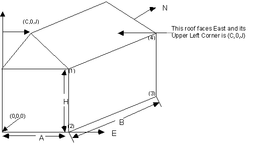
Figure 19. Illustration for Surface Vertices
The figure above will help illustrate Surface Vertex entry. The convention used in “GlobalGeometryRules” dictates the order of the vertices (ref: GlobalGeometryRules). In this example, the conventions used are Starting Vertex Position = UpperLeftCorner and Vertex Entry Direction= CounterClockwise. The surfaces for this single zone are:
4,0,0,H, 0,0,0, A,0,0, A,0,H; ! (4 vertices, South Wall)
4,A,0,H,A,0,0,A,B,0,A,B,H; ! (4 vertices, East Wall)
ignore other walls that are not shown in this figure
4,C,0,J,A,0,H,A,B,H,C,B,J; ! (4 vertices, roof)
3,C,0,J,0,0,H,A,0,H; ! (3 vertices, gable end)
4,0,0,H, 0,0,0, A,0,0, A,0,H; ! (4 vertices, South Wall)
Note that in this example, point 1 of the entry is the Upper Left Corner of the rectangular surfaces and the point of the triangle for the 3 sided surface. The east wall shows the order of vertex entry. For horizontal surfaces, any vertex may be chosen as the starting position, but the Vertex Entry Direction convention must be followed. The surface details report (Output: Surfaces:List, Details;) is very useful for reviewing the accuracy of surface geometry inputs (ref: Surface Output Variables/Reports and Variable Dictionary Reports).
From the detailed vertices, EnergyPlus tries to determine the “height” and “width” of the surface. Obviously, this doesn’t work well for >4 sided surfaces; for these, if the calculated height and width are not close to the gross area for the surface, the height and width shown will be the square root of the area (and thus a square).
A building surface is necessary for all calculations. There must be at least one building surface per zone. You can use the detailed descriptions as shown below or the simpler, rectangular surface descriptions shown earlier.
The Wall:Detailed object is used to describe walls.
This is a unique name associated with each building surface. It is used in several other places as a reference (e.g. as the base surface name for a Window or Door).
This is the name of the construction (ref: Construction) used in the surface. Regardless of location in the building, the “full” construction (all layers) is used. For example, for an interior wall separating two zones, zone x would have the outside layer (e.g. drywall) as the material that shows in zone y and then the layers to the inside layer – the material that shows in zone x. For symmetric constructions, the same construction can be used in the surfaces described in both zones.
This is the zone name to which the surface belongs.
This value can be one of several things depending on the actual kind of surface.
1) Surface – if this surface is an internal surface, then this is the choice. The value will either be a surface in the base zone or a surface in another zone. The heat balance between two zones can be accurately simulated by specifying a surface in an adjacent zone. EnergyPlus will simulate a group of zones simultaneously and will include the heat transfer between zones. However, as this increases the complexity of the calculations, it is not necessary to specify the other zone unless the two zones will have a significant temperature difference. If the two zones will not be very different (temperature wise), then the surface should use itself as the outside environment or specify this field as Adiabatic. The surface name on the “outside” of this surface (adjacent to) is placed in the next field.
2) Adiabatic – an internal surface in the same Zone. This surface will not transfer heat out of the zone, but will still store heat in thermal mass. Only the inside face of the surface will exchange heat with the zone (i.e. two adiabatic surfaces are required to model internal partitions where both sides of the surface are exchanging heat with the zone). The Outside Boundary Condition Object can be left blank.
3) Zone – this is similar to Surface but EnergyPlus will automatically create the required surface in the adjacent zone when this is entered for the surface. If there are windows or doors on the surface, EnergyPlus automatically creates appropriate sub-surfaces as well.
4) Outdoors – if this surface is exposed to outside temperature conditions, then this is the choice. See Sun Exposure and Wind Exposure below for further specifications on this kind of surface.
5) Ground – if this surface is exposed to the ground, then this is the usual choice. The temperature on the outside of this surface will be the Site:GroundTemperature:Surface value for the month. For more information on ground contact surfaces, reference the Auxiliary Programs document section on “Ground Heat Transfer in EnergyPlus”.
6) GroundFCfactorMethod – if this surface is exposed to the ground and using the Construction:CfactorUndergroundWall, then this is the choice. The temperature on the outside of this surface will be the Site:GroundTemperature:FcfactorMethod value for the month.
7) OtherSideCoefficients – if this surface has a custom, user specified temperature or other parameters (See SurfaceProperty:OtherSideCoefficients specification), then this is the choice. The outside boundary condition will be the name of the SurfaceProperty:OtherSideCoefficients specification.
8) OtherSideConditionsModel – if this surface has a specially-modeled multi-skin component, such as a transpired collector or vented photovoltaic panel, attached to the outside (See SurfaceProperty:OtherSideConditionsModel specification), then this the choice. The outside face environment will be the name of the SurfaceProperty:OtherSideConditionsModelspecification.
9) GroundSlabPreprocessorAverage – uses the average results from the Slab preprocessor calculations.
10) GroundSlabPreprocessorCore – uses the core results from the Slab preprocessor calculations.
11) GroundSlabPreprocessorPerimeter – uses the perimeter results from the Slab preprocessor calculations.
12) GroundBasementPreprocessorAverageWall – uses the average wall results from the Basement preprocessor calculations.
13) GroundBasementPreprocessorAverageFloor – uses the average floor results from the Basement preprocessor calculations.
14) GroundBasementPreprocessorUpperWall – uses the upper wall results from the Basement preprocessor calculations.
15) GroundBasementPreprocessorLowerWall – uses the lower wall results from the Basement preprocessor calculations.
If neither Surface, OtherSideCoefficients, or OtherSideConditionsModel are specified for the Outside Boundary Condition (previous field), then this field should be left blank.
As stated above, if the Outside Boundary Condition is “Surface”, then this field’s value must be the surface name whose inside face temperature will be forced on the outside face of the base surface. This permits heat exchange between adjacent zones (interzone heat transfer) when multiple zones are simulated, but can also be used to simulate middle zone behavior without modeling the adjacent zones. This is done by specifying a surface within the zone. For example, a middle floor zone can be modeled by making the floor the Outside Boundary Condition Object for the ceiling, and the ceiling the Outside Boundary Condition Object for the floor.
If the Outside Boundary Condition is Zone, then this field should contain the zone name of the adjacent zone for the surface.
Note: Zones with interzone heat transfer are not adiabatic and the internal surfaces contribute to gains or losses. Adiabatic surfaces are modeled by specifying the base surface itself in this field. Also, for interzone heat transfer, both surfaces must be represented – for example, if you want interzone heat transfer to an attic space, the ceiling in the lower zone must have a surface object with the outside face environment as the floor in the attic and, likewise, there must be a floor surface object in the attic that references the ceiling surface name in the lower zone.
Equally, if the Outside Boundary Condition is “OtherSideCoefficients”, then this field’s value must be the SurfaceProperty:OtherSideCoefficients name. Or if the Outside Boundary Condition is “OtherSideConditionsModel” then this field’s value must be the SurfaceProperty:OtherSideConditionsModel name.
If the surface is exposed to the sun, then “SunExposed” should be entered in this field. Otherwise, “NoSun” should be entered.
Note, a cantilevered floor could have “Outdoors” but “NoSun” exposure.
If the surface is exposed to the Wind, then “WindExposed” should be entered in this field. Otherwise, “NoWind” should be entered.
Note: When a surface is specified with “NoWind”, this has several implications. Within the heat balance code, this surface will default to using the simple ASHRAE exterior convection coefficient correlation with a zero wind speed. In addition, since the ASHRAE simple method does not have a separate value for equivalent long wavelength radiation to the sky and ground, using “NoWind” also eliminates long wavelength radiant exchange from the exterior of the surface to both the sky and the ground. Thus, only simple convection takes place at the exterior face of a surface specified with “NoWind”.
The fraction of the ground plane (assumed horizontal) that is visible from a heat-transfer surface. It is used to calculate the diffuse solar radiation from the ground that is incident on the surface.
For example, if there are no obstructions, a vertical surface sees half of the ground plane and so View Factor to Ground = 0.5. A horizontal downward-facing surface sees the entire ground plane, so View Factor to Ground = 1.0. A horizontal upward-facing surface (horizontal roof) does not see the ground at all, so View Factor to Ground = 0.0.
Unused if reflections option in Solar Distribution field in Building object input unless a DaylightingDevice:Shelf or DaylightingDevice:Tubular has been specified.
If you do not use the reflections option in the Solar Distribution field in your Building object input, you are responsible for entering the View Factor to Ground for each heat-transfer surface. Typical values for a surface that is not shadowed are obtained by the simple equation:
View Factor to Ground = (1-cos(SurfTilt))/2
For example, this gives 0.5 for a wall of tilt 90°. If the tilt of the wall changes, then the View Factor to Ground must also change.
If you enter autocalculate in this field, EnergyPlus will automatically calculate the view factor to ground based on the tilt of the surface.
If you do use the reflections option in the Solar Distribution field in your Building object input, you do not have to enter View Factor to Ground values. In this case the program will automatically calculate the value to use for each exterior surface taking into account solar shadowing (including shadowing of the ground by the building) and reflections from obstructions (ref: Building, Field: Solar Distribution).
However, if you do use the reflections option AND you are modeling a DaylightingDevice:Shelf or DaylightingDevice:Tubular, then you still need to enter some values of View Factor to Ground. For DaylightingDevice:Shelf you need to enter View Factor to Ground for the window associated with the shelf. And for DaylightingDevice:Tubular you need to enter the View Factor to Ground for the FenestrationSurface:Detailed corresponding to the dome of the tubular device.
Note 1: The corresponding view factor to the sky for diffuse solar radiation is not a user input; it is calculated within EnergyPlus based on surface orientation, sky solar radiance distribution, and shadowing surfaces.
Note 2: The view factors to the sky and ground for thermal infrared (long-wave) radiation are not user inputs; they are calculated within EnergyPlus based on surface tilt and shadowing surfaces. Shadowing surfaces are considered to have the same emissivity and temperature as the ground, so they are lumped together with the ground in calculating the ground IR view factor.
This field specifies the number of sides in the surface (number of X,Y,Z vertex groups). For further information, see the discussion on “Surface Vertices” above.
The RoofCeiling:Detailed object is used to describe walls.
This is a unique name associated with each building surface. It is used in several other places as a reference (e.g. as the base surface name for a Window or Door).
This is the name of the construction (ref: Construction) used in the surface. Regardless of location in the building, the “full” construction (all layers) is used. For example, for an interior wall separating two zones, zone x would have the outside layer (e.g. drywall) as the material that shows in zone y and then the layers to the inside layer – the material that shows in zone x. For symmetric constructions, the same construction can be used in the surfaces described in both zones.
This is the zone name to which the surface belongs.
This value can be one of several things depending on the actual kind of surface.
1) Surface – if this surface is an internal surface, then this is the choice. The value will either be a surface in the base zone or a surface in another zone. The heat balance between two zones can be accurately simulated by specifying a surface in an adjacent zone. EnergyPlus will simulate a group of zones simultaneously and will include the heat transfer between zones. However, as this increases the complexity of the calculations, it is not necessary to specify the other zone unless the two zones will have a significant temperature difference. If the two zones will not be very different (temperature wise), then the surface should use itself as the outside environment or specify this field as Adiabatic. The surface name on the “outside” of this surface (adjacent to) is placed in the next field.
2) Adiabatic – an internal surface in the same Zone. This surface will not transfer heat out of the zone, but will still store heat in thermal mass. Only the inside face of the surface will exchange heat with the zone (i.e. two adiabatic surfaces are required to model internal partitions where both sides of the surface are exchanging heat with the zone). The Outside Boundary Condition Object can be left blank.
3) Zone – this is similar to Surface but EnergyPlus will automatically create the required surface in the adjacent zone when this is entered for the surface. If there are windows or doors on the surface, EnergyPlus automatically creates appropriate sub-surfaces as well.
4) Outdoors – if this surface is exposed to outside temperature conditions, then this is the choice. See Sun Exposure and Wind Exposure below for further specifications on this kind of surface.
5) Ground – if this surface is exposed to the ground, then this is the choice. The temperature on the outside of this surface will be the Ground Temperature.
6) OtherSideCoefficients – if this surface has a custom, user specified temperature or other parameters (See SurfaceProperty:OtherSideCoefficients specification), then this is the choice. The outside boundary condition will be the name of the SurfaceProperty:OtherSideCoefficients specification.
7) OtherSideConditionsModel – if this surface has a specially-modeled multi-skin component, such as a transpired collector or vented photovoltaic panel, attached to the outside (See SurfaceProperty:OtherSideConditionsModel specification), then this the choice. The outside face environment will be the name of the SurfaceProperty:OtherSideConditionsModelspecification.
8) GroundSlabPreprocessorAverage – uses the average results from the Slab preprocessor calculations.
9) GroundSlabPreprocessorCore – uses the core results from the Slab preprocessor calculations.
10) GroundSlabPreprocessorPerimeter – uses the perimeter results from the Slab preprocessor calculations.
11) GroundBasementPreprocessorAverageWall – uses the average wall results from the Basement preprocessor calculations.
12) GroundBasementPreprocessorAverageFloor – uses the average floor results from the Basement preprocessor calculations.
13) GroundBasementPreprocessorUpperWall – uses the upper wall results from the Basement preprocessor calculations.
14) GroundBasementPreprocessorLowerWall – uses the lower wall results from the Basement preprocessor calculations.
If neither Surface, OtherSideCoefficients, or OtherSideConditionsModel are specified for the Outside Boundary Condition (previous field), then this field should be left blank.
As stated above, if the Outside Boundary Condition is “Surface”, then this field’s value must be the surface name whose inside face temperature will be forced on the outside face of the base surface. This permits heat exchange between adjacent zones (interzone heat transfer) when multiple zones are simulated, but can also be used to simulate middle zone behavior without modeling the adjacent zones. This is done by specifying a surface within the zone. For example, a middle floor zone can be modeled by making the floor the Outside Boundary Condition Object for the ceiling, and the ceiling the Outside Boundary Condition Object for the floor.
If the Outside Boundary Condition is Zone, then this field should contain the zone name of the adjacent zone for the surface.
Note: Zones with interzone heat transfer are not adiabatic and the internal surfaces contribute to gains or losses. Adiabatic surfaces are modeled by specifying the base surface itself in this field. Also, for interzone heat transfer, both surfaces must be represented – for example, if you want interzone heat transfer to an attic space, the ceiling in the lower zone must have a surface object with the outside face environment as the floor in the attic and, likewise, there must be a floor surface object in the attic that references the ceiling surface name in the lower zone.
Equally, if the Outside Boundary Condition is “OtherSideCoefficients”, then this field’s value must be the SurfaceProperty:OtherSideCoefficients name. Or if the Outside Boundary Condition is “OtherSideConditionsModel” then this field’s value must be the SurfaceProperty:OtherSideConditionsModel name.
If the surface is exposed to the sun, then “SunExposed” should be entered in this field. Otherwise, “NoSun” should be entered.
Note, a cantilevered floor could have “Outdoors” but “NoSun” exposure.
If the surface is exposed to the Wind, then “WindExposed” should be entered in this field. Otherwise, “NoWind” should be entered.
Note: When a surface is specified with “NoWind”, this has several implications. Within the heat balance code, this surface will default to using the simple ASHRAE exterior convection coefficient correlation with a zero wind speed. In addition, since the ASHRAE simple method does not have a separate value for equivalent long wavelength radiation to the sky and ground, using “NoWind” also eliminates long wavelength radiant exchange from the exterior of the surface to both the sky and the ground. Thus, only simple convection takes place at the exterior face of a surface specified with “NoWind”.
The fraction of the ground plane (assumed horizontal) that is visible from a heat-transfer surface. It is used to calculate the diffuse solar radiation from the ground that is incident on the surface.
For example, if there are no obstructions, a vertical surface sees half of the ground plane and so View Factor to Ground = 0.5. A horizontal downward-facing surface sees the entire ground plane, so View Factor to Ground = 1.0. A horizontal upward-facing surface (horizontal roof) does not see the ground at all, so View Factor to Ground = 0.0.
Unused if reflections option in Solar Distribution field in Building object input unless a DaylightingDevice:Shelf or DaylightingDevice:Tubular has been specified.
If you do not use the reflections option in the Solar Distribution field in your Building object input, you are responsible for entering the View Factor to Ground for each heat-transfer surface. Typical values for a surface that is not shadowed are obtained by the simple equation:
View Factor to Ground = (1-cos(SurfTilt))/2
For example, this gives 0.5 for a wall of tilt 90°. If the tilt of the wall changes, then the View Factor to Ground must also change.
If you enter autocalculate in this field, EnergyPlus will automatically calculate the view factor to ground based on the tilt of the surface.
If you do use the reflections option in the Solar Distribution field in your Building object input, you do not have to enter View Factor to Ground values. In this case the program will automatically calculate the value to use for each exterior surface taking into account solar shadowing (including shadowing of the ground by the building) and reflections from obstructions (ref: Building, Field: Solar Distribution).
However, if you do use the reflections option AND you are modeling a DaylightingDevice:Shelf or DaylightingDevice:Tubular, then you still need to enter some values of View Factor to Ground. For DaylightingDevice:Shelf you need to enter View Factor to Ground for the window associated with the shelf. And for DaylightingDevice:Tubular you need to enter the View Factor to Ground for the FenestrationSurface:Detailed corresponding to the dome of the tubular device.
Note 1: The corresponding view factor to the sky for diffuse solar radiation is not a user input; it is calculated within EnergyPlus based on surface orientation, sky solar radiance distribution, and shadowing surfaces.
Note 2: The view factors to the sky and ground for thermal infrared (long-wave) radiation are not user inputs; they are calculated within EnergyPlus based on surface tilt and shadowing surfaces. Shadowing surfaces are considered to have the same emissivity and temperature as the ground, so they are lumped together with the ground in calculating the ground IR view factor.
This field specifies the number of sides in the surface (number of X,Y,Z vertex groups). For further information, see the discussion on “Surface Vertices” above.
The Floor:Detailed object is used to describe walls.
This is a unique name associated with each building surface. It is used in several other places as a reference (e.g. as the base surface name for a Window or Door).
This is the name of the construction (ref: Construction) used in the surface. Regardless of location in the building, the “full” construction (all layers) is used. For example, for an interior wall separating two zones, zone x would have the outside layer (e.g. drywall) as the material that shows in zone y and then the layers to the inside layer – the material that shows in zone x. For symmetric constructions, the same construction can be used in the surfaces described in both zones.
This is the zone name to which the surface belongs.
This value can be one of several things depending on the actual kind of surface.
1) Surface – if this surface is an internal surface, then this is the choice. The value will either be a surface in the base zone or a surface in another zone. The heat balance between two zones can be accurately simulated by specifying a surface in an adjacent zone. EnergyPlus will simulate a group of zones simultaneously and will include the heat transfer between zones. However, as this increases the complexity of the calculations, it is not necessary to specify the other zone unless the two zones will have a significant temperature difference. If the two zones will not be very different (temperature wise), then the surface should use itself as the outside environment or specify this field as Adiabatic. The surface name on the “outside” of this surface (adjacent to) is placed in the next field.
2) Adiabatic – an internal surface in the same Zone. This surface will not transfer heat out of the zone, but will still store heat in thermal mass. Only the inside face of the surface will exchange heat with the zone (i.e. two adiabatic surfaces are required to model internal partitions where both sides of the surface are exchanging heat with the zone). The Outside Boundary Condition Object can be left blank.
3) Zone – this is similar to Surface but EnergyPlus will automatically create the required surface in the adjacent zone when this is entered for the surface. If there are windows or doors on the surface, EnergyPlus automatically creates appropriate sub-surfaces as well.
4) Outdoors – if this surface is exposed to outside temperature conditions, then this is the choice. See Sun Exposure and Wind Exposure below for further specifications on this kind of surface.
5) Ground – if this surface is exposed to the ground, then this is the usual choice. The temperature on the outside of this surface will be the Site:GroundTemperature:Surface value for the month. For more information on ground contact surfaces, reference the Auxiliary Programs document section on “Ground Heat Transfer in EnergyPlus”.
6) GroundFCfactorMethod – if this surface is exposed to the ground and using the Construction:FfactorGroundFloor, then this is the choice. The temperature on the outside of this surface will be the Site:GroundTemperature:FcfactorMethod value for the month.
7) OtherSideCoefficients – if this surface has a custom, user specified temperature or other parameters (See SurfaceProperty:OtherSideCoefficients specification), then this is the choice. The outside boundary condition will be the name of the SurfaceProperty:OtherSideCoefficients specification.
8) OtherSideConditionsModel – if this surface has a specially-modeled multi-skin component, such as a transpired collector or vented photovoltaic panel, attached to the outside (See SurfaceProperty:OtherSideConditionsModel specification), then this the choice. The outside face environment will be the name of the SurfaceProperty:OtherSideConditionsModelspecification.
9) GroundSlabPreprocessorAverage – uses the average results from the Slab preprocessor calculations.
10) GroundSlabPreprocessorCore – uses the core results from the Slab preprocessor calculations.
11) GroundSlabPreprocessorPerimeter – uses the perimeter results from the Slab preprocessor calculations.
12) GroundBasementPreprocessorAverageWall – uses the average wall results from the Basement preprocessor calculations.
13) GroundBasementPreprocessorAverageFloor – uses the average floor results from the Basement preprocessor calculations.
14) GroundBasementPreprocessorUpperWall – uses the upper wall results from the Basement preprocessor calculations.
15) GroundBasementPreprocessorLowerWall – uses the lower wall results from the Basement preprocessor calculations.
If neither Surface, OtherSideCoefficients, or OtherSideConditionsModel are specified for the Outside Boundary Condition (previous field), then this field should be left blank.
As stated above, if the Outside Boundary Condition is “Surface”, then this field’s value must be the surface name whose inside face temperature will be forced on the outside face of the base surface. This permits heat exchange between adjacent zones (interzone heat transfer) when multiple zones are simulated, but can also be used to simulate middle zone behavior without modeling the adjacent zones. This is done by specifying a surface within the zone. For example, a middle floor zone can be modeled by making the floor the Outside Boundary Condition Object for the ceiling, and the ceiling the Outside Boundary Condition Object for the floor.
If the Outside Boundary Condition is Zone, then this field should contain the zone name of the adjacent zone for the surface.
Note: Zones with interzone heat transfer are not adiabatic and the internal surfaces contribute to gains or losses. Adiabatic surfaces are modeled by specifying the base surface itself in this field. Also, for interzone heat transfer, both surfaces must be represented – for example, if you want interzone heat transfer to an attic space, the ceiling in the lower zone must have a surface object with the outside face environment as the floor in the attic and, likewise, there must be a floor surface object in the attic that references the ceiling surface name in the lower zone.
Equally, if the Outside Boundary Condition is “OtherSideCoefficients”, then this field’s value must be the SurfaceProperty:OtherSideCoefficients name. Or if the Outside Boundary Condition is “OtherSideConditionsModel” then this field’s value must be the SurfaceProperty:OtherSideConditionsModel name.
If the surface is exposed to the sun, then “SunExposed” should be entered in this field. Otherwise, “NoSun” should be entered.
Note, a cantilevered floor could have “Outdoors” but “NoSun” exposure.
If the surface is exposed to the Wind, then “WindExposed” should be entered in this field. Otherwise, “NoWind” should be entered.
Note: When a surface is specified with “NoWind”, this has several implications. Within the heat balance code, this surface will default to using the simple ASHRAE exterior convection coefficient correlation with a zero wind speed. In addition, since the ASHRAE simple method does not have a separate value for equivalent long wavelength radiation to the sky and ground, using “NoWind” also eliminates long wavelength radiant exchange from the exterior of the surface to both the sky and the ground. Thus, only simple convection takes place at the exterior face of a surface specified with “NoWind”.
The fraction of the ground plane (assumed horizontal) that is visible from a heat-transfer surface. It is used to calculate the diffuse solar radiation from the ground that is incident on the surface.
For example, if there are no obstructions, a vertical surface sees half of the ground plane and so View Factor to Ground = 0.5. A horizontal downward-facing surface sees the entire ground plane, so View Factor to Ground = 1.0. A horizontal upward-facing surface (horizontal roof) does not see the ground at all, so View Factor to Ground = 0.0.
Unused if reflections option in Solar Distribution field in Building object input unless a DaylightingDevice:Shelf or DaylightingDevice:Tubular has been specified.
If you do not use the reflections option in the Solar Distribution field in your Building object input, you are responsible for entering the View Factor to Ground for each heat-transfer surface. Typical values for a surface that is not shadowed are obtained by the simple equation:
View Factor to Ground = (1-cos(SurfTilt))/2
For example, this gives 0.5 for a wall of tilt 90°. If the tilt of the wall changes, then the View Factor to Ground must also change.
If you enter autocalculate in this field, EnergyPlus will automatically calculate the view factor to ground based on the tilt of the surface.
If you do use the reflections option in the Solar Distribution field in your Building object input, you do not have to enter View Factor to Ground values. In this case the program will automatically calculate the value to use for each exterior surface taking into account solar shadowing (including shadowing of the ground by the building) and reflections from obstructions (ref: Building, Field: Solar Distribution).
However, if you do use the reflections option AND you are modeling a DaylightingDevice:Shelf or DaylightingDevice:Tubular, then you still need to enter some values of View Factor to Ground. For DaylightingDevice:Shelf you need to enter View Factor to Ground for the window associated with the shelf. And for DaylightingDevice:Tubular you need to enter the View Factor to Ground for the FenestrationSurface:Detailed corresponding to the dome of the tubular device.
Note 1: The corresponding view factor to the sky for diffuse solar radiation is not a user input; it is calculated within EnergyPlus based on surface orientation, sky solar radiance distribution, and shadowing surfaces.
Note 2: The view factors to the sky and ground for thermal infrared (long-wave) radiation are not user inputs; they are calculated within EnergyPlus based on surface tilt and shadowing surfaces. Shadowing surfaces are considered to have the same emissivity and temperature as the ground, so they are lumped together with the ground in calculating the ground IR view factor.
This field specifies the number of sides in the surface (number of X,Y,Z vertex groups). For further information, see the discussion on “Surface Vertices” above.
Some examples of using these objects:
Floor:Detailed,
Floor_NorthZone_1stFloor,!- Name
FLOOR-SLAB-ASSEMBLY, !- Construction Name
NorthZone_1stFloor, !- Zone Name
Ground, !- Outside Boundary Condition
, !- Outside Boundary Condition Object
NoSun, !- Sun Exposure
NoWind, !- Wind Exposure
0.0, !- View Factor to Ground
4, !- Number of Vertices
0, 11, 0, !- X,Y,Z 1 {m}
25, 11, 0, !- X,Y,Z 2 {m}
25, 5.5, 0, !- X,Y,Z 3 {m}
0, 5.5, 0; !- X,Y,Z 4 {m}
RoofCeiling:Detailed,
Ceiling_SouthZone_1stFloor, !- Name
CEILING-FLOOR-ASSEMBLY, !- Construction Name
SouthZone_1stFloor, !- Zone Name
Surface, !- Outside Boundary Condition
Floor_SouthZone_2ndFloor,!- Outside Boundary Condition Object
NoSun, !- Sun Exposure
NoWind, !- Wind Exposure
0.0, !- View Factor to Ground
4, !- Number of Vertices
0, 0, 3.4, !- X,Y,Z 1 {m}
25, 0, 3.4, !- X,Y,Z 2 {m}
25, 5.5, 3.4, !- X,Y,Z 3 {m}
0, 5.5, 3.4; !- X,Y,Z 4 {m}
Wall:Detailed,
InteriorWall_SouthZone_1stFloor, !- Name
INTERIOR-WALL-ASSEMBLY, !- Construction Name
SouthZone_1stFloor, !- Zone Name
Surface, !- Outside Boundary Condition
InteriorWall_NorthZone_1stFloor, !- Outside Boundary Condition Object
NoSun, !- Sun Exposure
NoWind, !- Wind Exposure
0, !- View Factor to Ground
4, !- Number of Vertices
25, 5.5, 3.7, !- X,Y,Z 1 {m}
25, 5.5, 0, !- X,Y,Z 2 {m}
0, 5.5, 0, !- X,Y,Z 3 {m}
0, 5.5, 3.7; !- X,Y,Z 4 {m}
The BuildingSurface:Detailed object can more generally describe each of the surfaces.
This is a unique name associated with each building surface. It is used in several other places as a reference (e.g. as the base surface name for a Window or Door).
Used primarily for convenience, the surface type can be one of the choices illustrated above – Wall, Floor, Ceiling, Roof. Azimuth (facing) and Tilt are determined from the vertex coordinates. Note that “normal” floors will be tilted 180° whereas flat roofs/ceilings will be tilted 0°. EnergyPlus uses this field’s designation, along with the calculated tilt of the surface, to issue warning messages when tilts are “out of range”. Calculations in EnergyPlus use the actual calculated tilt values for the actual heat balance calculations. Note, however, that a floor tilted 0° is really facing “into” the zone and is not what you will desire for the calculations even though the coordinate may appear correct in the viewed DXF display.
“Normal” tilt for walls is 90° -- here you may use the calculated Azimuth to make sure your walls are facing away from the zone’s interior.
This is the name of the construction (ref: Construction) used in the surface. Regardless of location in the building, the “full” construction (all layers) is used. For example, for an interior wall separating two zones, zone x would have the outside layer (e.g. drywall) as the material that shows in zone y and then the layers to the inside layer – the material that shows in zone x. For symmetric constructions, the same construction can be used in the surfaces described in both zones.
This is the zone name to which the surface belongs.
This value can be one of several things depending on the actual kind of surface.
1) Surface – if this surface is an internal surface, then this is the choice. The value will either be a surface in the base zone or a surface in another zone. The heat balance between two zones can be accurately simulated by specifying a surface in an adjacent zone. EnergyPlus will simulate a group of zones simultaneously and will include the heat transfer between zones. However, as this increases the complexity of the calculations, it is not necessary to specify the other zone unless the two zones will have a significant temperature difference. If the two zones will not be very different (temperature wise), then the surface should use itself as the outside environment or specify this field as Adiabatic. In either case, the surface name on the “outside” of this surface (adjacent to) is placed in the next field.
2) Adiabatic – an internal surface in the same Zone. This surface will not transfer heat out of the zone, but will still store heat in thermal mass. Only the inside face of the surface will exchange heat with the zone (i.e. two adiabatic surfaces are required to model internal partitions where both sides of the surface are exchanging heat with the zone). The Outside Boundary Condition Object can be left blank.
3) Zone – this is similar to Surface but EnergyPlus will automatically create the required surface in the adjacent zone when this is entered for the surface. If there are windows or doors on the surface, EnergyPlus automatically creates appropriate sub-surfaces as well.
4) Outdoors – if this surface is exposed to outside temperature conditions, then this is the choice. See Sun Exposure and Wind Exposure below for further specifications on this kind of surface.
5) Ground – if this surface is exposed to the ground, then this is the usual choice. The temperature on the outside of this surface will be the Site:GroundTemperature:Surface value for the month. For more information on ground contact surfaces, reference the Auxiliary Programs document section on “Ground Heat Transfer in EnergyPlus”.
6) GroundFCfactorMethod – if this surface is exposed to the ground and using the Construction:CfactorUndergroundWall or Construction:FfactorGroundFloor (depending on surface type), then this is the choice. The temperature on the outside of this surface will be the Site:GroundTemperature:FcfactorMethod value for the month.
7) OtherSideCoefficients – if this surface has a custom, user specified temperature or other parameters (See SurfaceProperty:OtherSideCoefficients specification), then this is the choice. The outside boundary condition will be the name of the SurfaceProperty:OtherSideCoefficients specification.
8) OtherSideConditionsModel – if this surface has a specially-modeled multi-skin component, such as a transpired collector or vented photovoltaic panel, attached to the outside (See SurfaceProperty:OtherSideConditionsModel specification), then this the choice. The outside face environment will be the name of the SurfaceProperty:OtherSideConditionsModelspecification.
9) GroundSlabPreprocessorAverage – uses the average results from the Slab preprocessor calculations.
10) GroundSlabPreprocessorCore – uses the core results from the Slab preprocessor calculations.
11) GroundSlabPreprocessorPerimeter – uses the perimeter results from the Slab preprocessor calculations.
12) GroundBasementPreprocessorAverageWall – uses the average wall results from the Basement preprocessor calculations.
13) GroundBasementPreprocessorAverageFloor – uses the average floor results from the Basement preprocessor calculations.
14) GroundBasementPreprocessorUpperWall – uses the upper wall results from the Basement preprocessor calculations.
15) GroundBasementPreprocessorLowerWall – uses the lower wall results from the Basement preprocessor calculations.
If neither Surface, OtherSideCoefficients, or OtherSideConditionsModel are specified for the Outside Boundary Condition (previous field), then this field should be left blank.
As stated above, if the Outside Boundary Condition is “Surface”, then this field’s value must be the surface name whose inside face temperature will be forced on the outside face of the base surface. This permits heat exchange between adjacent zones (interzone heat transfer) when multiple zones are simulated, but can also be used to simulate middle zone behavior without modeling the adjacent zones. This is done by specifying a surface within the zone. For example, a middle floor zone can be modeled by making the floor the Outside Boundary Condition Object for the ceiling, and the ceiling the Outside Boundary Condition Object for the floor.
If the Outside Boundary Condition is Zone, then this field should contain the zone name of the adjacent zone for the surface.
Note: Zones with interzone heat transfer are not adiabatic and the internal surfaces contribute to gains or losses. Adiabatic surfaces are modeled by specifying the base surface itself in this field. Also, for interzone heat transfer, both surfaces must be represented – for example, if you want interzone heat transfer to an attic space, the ceiling in the lower zone must have a surface object with the outside face environment as the floor in the attic and, likewise, there must be a floor surface object in the attic that references the ceiling surface name in the lower zone.
Equally, if the Outside Boundary Condition is “OtherSideCoefficients”, then this field’s value must be the SurfaceProperty:OtherSideCoefficients name. Or if the Outside Boundary Condition is “OtherSideConditionsModel” then this field’s value must be the SurfaceProperty:OtherSideConditionsModel name.
If the surface is exposed to the sun, then “SunExposed” should be entered in this field. Otherwise, “NoSun” should be entered.
Note, a cantilevered floor could have “Outdoors” but “NoSun” exposure.
If the surface is exposed to the Wind, then “WindExposed” should be entered in this field. Otherwise, “NoWind” should be entered.
Note: When a surface is specified with “NoWind”, this has several implications. Within the heat balance code, this surface will default to using the simple ASHRAE exterior convection coefficient correlation with a zero wind speed. In addition, since the ASHRAE simple method does not have a separate value for equivalent long wavelength radiation to the sky and ground, using “NoWind” also eliminates long wavelength radiant exchange from the exterior of the surface to both the sky and the ground. Thus, only simple convection takes place at the exterior face of a surface specified with “NoWind”.
The fraction of the ground plane (assumed horizontal) that is visible from a heat-transfer surface. It is used to calculate the diffuse solar radiation from the ground that is incident on the surface.
For example, if there are no obstructions, a vertical surface sees half of the ground plane and so View Factor to Ground = 0.5. A horizontal downward-facing surface sees the entire ground plane, so View Factor to Ground = 1.0. A horizontal upward-facing surface (horizontal roof) does not see the ground at all, so View Factor to Ground = 0.0.
Unused if reflections option in Solar Distribution field in Building object input unless a DaylightingDevice:Shelf or DaylightingDevice:Tubular has been specified.
If you do not use the reflections option in the Solar Distribution field in your Building object input, you are responsible for entering the View Factor to Ground for each heat-transfer surface. Typical values for a surface that is not shadowed are obtained by the simple equation:
View Factor to Ground = (1-cos(SurfTilt))/2
For example, this gives 0.5 for a wall of tilt 90°. If the tilt of the wall changes, then the View Factor to Ground must also change.
If you enter autocalculate in this field, EnergyPlus will automatically calculate the view factor to ground based on the tilt of the surface.
If you do use the reflections option in the Solar Distribution field in your Building object input, you do not have to enter View Factor to Ground values. In this case the program will automatically calculate the value to use for each exterior surface taking into account solar shadowing (including shadowing of the ground by the building) and reflections from obstructions (ref: Building, Field: Solar Distribution).
However, if you do use the reflections option AND you are modeling a DaylightingDevice:Shelf or DaylightingDevice:Tubular, then you still need to enter some values of View Factor to Ground. For DaylightingDevice:Shelf you need to enter View Factor to Ground for the window associated with the shelf. And for DaylightingDevice:Tubular you need to enter the View Factor to Ground for the FenestrationSurface:Detailed corresponding to the dome of the tubular device.
Note 1: The corresponding view factor to the sky for diffuse solar radiation is not a user input; it is calculated within EnergyPlus based on surface orientation, sky solar radiance distribution, and shadowing surfaces.
Note 2: The view factors to the sky and ground for thermal infrared (long-wave) radiation are not user inputs; they are calculated within EnergyPlus based on surface tilt and shadowing surfaces. Shadowing surfaces are considered to have the same emissivity and temperature as the ground, so they are lumped together with the ground in calculating the ground IR view factor.
This field specifies the number of sides in the surface (number of X,Y,Z vertex groups). For further information, see the discussion on “Surface Vertices” above.
IDF example of three walls (first is an exterior wall, second and third are interzone partitions):
BuildingSurface:Detailed,Zn001:Wall001, !- Base Surface Name
Wall,EXTERIOR, !- Class and Construction Name
ZONE 1 @ 200 601 0 T, !- Zone
Outdoors,, !- Outside Boundary Condition and Target (if applicable)
SunExposed, !- Solar Exposure
WindExposed, !- Wind Exposure
0.5000000 , !- VF to Ground
4, !-Rectangle
0.0000000E+00, 0.0000000E+00, 3.048000 ,
0.0000000E+00, 0.0000000E+00, 0.0000000E+00,
6.096000 , 0.0000000E+00, 0.0000000E+00,
6.096000 , 0.0000000E+00, 3.048000 ;
BuildingSurface:Detailed,Zn001:Wall006, !- Base Surface Name
Wall,INTERIOR, !- Class and Construction Name
HEARTLAND AREA, !- Zone
Surface,Zn004:Wall005, !- Outside Boundary Conditions and Target (if applicable)
NoSun, !- Solar Exposure
NoWind, !- Wind Exposure
0.5000000 , !- VF to Ground
4, !-Rectangle
38.01000 , 28.25000 , 10.00000 ,
38.01000 , 28.25000 , 0.0000000E+00,
38.01000 , 18.25000 , 0.0000000E+00,
38.01000 , 18.25000 , 10.00000 ;
BuildingSurface:Detailed,Zn001:Wall007, !- Base Surface Name
Wall,INTERIOR, !- Class and Construction Name
HEARTLAND AREA, !- Zone
Surface,Zn003:Wall006, !- Outside Boundary Conditions and Target (if applicable)
NoSun, !- Solar Exposure
NoWind, !- Wind Exposure
0.5000000 , !- VF to Ground
4, !-Rectangle
58.01000 , 18.25000 , 10.00000 ,
58.01000 , 18.25000 , 0.0000000E+00,
58.01000 , 28.25000 , 0.0000000E+00,
58.01000 , 28.25000 , 10.00000 ;
This surface class is used for subsurfaces, which can be of five different types: Windows, Doors, GlassDoors, TubularDaylightDomes, and TubularDaylightDiffusers. A subsurface (such as a window) of a base surface (such as a wall) inherits several of the properties (such as Outside Boundary Condition, Sun Exposure, etc.) of the base surface. Windows, GlassDoors, TubularDaylightDomes, and TubularDaylightDiffusers are considered to have one or more glass layers and so transmit solar radiation. Doors are considered to be opaque.
This is a unique name associated with the heat transfer subsurface. It may be used in other places as a reference (e.g. as the opposing subsurface of an interzone window or door).
The choices for Surface Type are Window, Door, GlassDoor, TubularDaylightDome, and TubularDaylightDiffuser. Doors are assumed to be opaque (do not transmit solar radiation) whereas the other surface types do transmit solar radiation. Windows and Glass Doors are treated identically in the calculation of conduction heat transfer, solar gain, daylighting, etc. A Window or GlassDoor, but not a Door, can have a movable interior, exterior or between-glass shading device, such as blinds (ref: WindowMaterial:Blind), and can have a frame and/or a divider (ref: WindowProperty:FrameAndDivider). TubularDaylightDomes and TubularDaylightDomes are specialized subsurfaces for use with the DaylightingDevice:Tubular object to simulate Tubular Daylighting Devices (TDDs). TubularDaylightDomes and TubularDaylightDomes cannot have shades, screens or blinds. In the following, the term “window” applies to Window, GlassDoor, TubularDaylightDome, and TubularDaylightDome, if not otherwise explicitly mentioned.
As noted in the description of the BuildingSurface:Detailed, Azimuth (facing angle) and Tilt are calculated from the entered vertices. Tilts of subsurfaces will normally be the same as their base surface. If these are significantly beyond the “normals” for the base surface, warning messages may be issued. If the facing angles are not correct, you may have a window pointing “into” the zone rather than out of it – this would cause problems in the calculations. Note, too, that a “reveal” (inset or outset) may occur if the plane of the subsurface is not coincident with the base surface; the reveal has an effect on shading of the subsurface.
This is the name of the subsurface’s construction (ref: Construction [for Window, GlassDoor and Door] and Construction:WindowDataFile [for Window and GlassDoor]).
For windows, if Construction Name is not found among the constructions on the input (.idf) file, the Window5 Data File (Window5DataFile.dat) will be searched for that Construction Name (see “Importing Windows from WINDOW 5”). If that file is not present or if the Construction Name does not match the name of an entry on the file, an error will result. If there is a match, a window construction and its corresponding glass and gas materials will be created from the information read from the file.
This is the name of a surface that contains this subsurface. Certain kinds of surfaces may not be allowed to have subsurfaces. For example, a surface in contact with the ground (Outside Boundary Condition = Ground) cannot contain a window.
If the base surface has Outside Boundary Condition = Surface or OtherSideCoefficients, then this field must also be specified for the subsurface. Otherwise, it can be left blank.
If the base surface has Outside Boundary Condition = Zone, then this surface retains that characteristic and uses the same zone of the base surface. It can be entered here for clarity or it can be left blank.
If Outside Boundary Condition for the base surface is Surface, this field should specify the subsurface in the opposing zone that is the counterpart to this subsurface. The constructions of the subsurface and opposing subsurface must match, except that, for multi-layer constructions, the layer order of the opposing subsurface’s construction must be the reverse of that of the subsurface.
If Outside Boundary Condition for the base surface is OtherSideCoefficients, this field could specify the set of SurfaceProperty:OtherSideCoefficients for this subsurface. If this is left blank, then the Other Side Coefficients of the base surface will be used for this subsurface. Windows and GlassDoors are not allowed to have Other Side Coefficients.
The fraction of the ground plane (assumed horizontal) that is visible from a heat-transfer surface. It is used to calculate the diffuse solar radiation from the ground that is incident on the surface.
For example, if there are no obstructions, a vertical surface sees half of the ground plane and so View Factor to Ground = 0.5. A horizontal downward-facing surface sees the entire ground plane, so View Factor to Ground = 1.0. A horizontal upward-facing surface (horizontal roof) does not see the ground at all, so View Factor to Ground = 0.0.
Unused if reflections option in Solar Distribution field in Building object input unless a Daylighting Device:Shelf or Daylighting Device:Tubular has been specified.
If you do not use the reflections option in the Solar Distribution field in your Building object input, you are responsible for entering the View Factor to Ground for each heat-transfer surface. Typical values for a surface that is not shadowed are obtained by the simple equation:
View Factor to Ground = (1-cos(SurfTilt))/2
For example, this gives 0.5 for a wall of tilt 90°. If the tilt of the wall changes, then the View Factor to Ground must also change.
If you enter autocalculate in this field, EnergyPlus will automatically calculate the view factor to ground based on the tilt of the surface.
If you do use the reflections option in the Solar Distribution field in your BUILDING object input, you do not have to enter View Factor to Ground values. In this case the program will automatically calculate the value to use for each exterior surface taking into account solar shadowing (including shadowing of the ground by the building) and reflections from obstructions (ref: Building, Field: Solar Distribution).
However, if you do use the reflections option AND you are modeling a DaylightingDevice:Shelf or DaylightingDevice:Tubular, then you still need to enter some values of View Factor to Ground. For DaylightingDevice:Shelf you need to enter View Factor to Ground for the window associated with the shelf. And for DaylightingDevice:Tubular you need to enter the View Factor to Ground for the FenestrationSurface:Detailed corresponding to the dome of the tubular device (ref: DaylightingDevice:Tubular).
Note 1: The corresponding view factor to the sky for diffuse solar radiation is not a user input; it is calculated within EnergyPlus based on surface orientation, sky solar radiance distribution, and shadowing surfaces.
Note 2: The view factors to the sky and ground for thermal infrared (long-wave) radiation are not user inputs; they are calculated within EnergyPlus based on surface tilt and shadowing surfaces. Shadowing surfaces are considered to have the same emissivity and temperature as the ground, so they are lumped together with the ground in calculating the ground infrared view factor.
This field, if not blank, is the name of the window shading control (ref: WindowProperty:ShadingControl) for this subsurface. It is used for Surface Type = Window and GlassDoor. To assign a shade to a window or glass door, see WindowMaterial: Shade. To assign a screen, see WindowMaterial:Screen. To assign a blind, see WindowMaterial:Blind. To assign switchable glazing, such as electrochromic glazing, see WindowProperty:ShadingControl.
This field, if not blank, can be used to specify window frame, divider and reveal-surface data (ref: WindowProperty:FrameAndDivider). It is used only for exterior GlassDoors and rectangular exterior Windows, i.e., those with OutsideFaceEnvironment = Outdoors.
This field should be blank for triangular windows.
Used only for Surface Type = Window, Door or Glass Door. It is the number of identical items on the base surface. Using Multiplier can save input effort and calculation time. In the calculation the area (and area of frame and divider, if present and surface type is a window) is multiplied by Multiplier. The calculation of shadowing on the subsurfaces (and the calculation of the interior distribution of beam solar radiation transmitted by windows and glass doors) are done for the specified subsurface position and dimensions.
Multiplier should be used with caution. Multiplier > 1 can give inaccurate or nonsensical results in situations where the results are sensitive to window or glass door position. This includes shadowing on the window/glass door, daylighting from the window/glass door, and interior distribution of solar radiation from the window/glass door. In these cases, the results for the single input window/glass door, after multiplication, may not be representative of the results you would get if you entered each of the multiple subsurfaces separately.
If Multiplier > 1, you will get
--a warning if Solar Distribution = FullExterior or FullInteriorAndExterior (ref: Building - Field: Solar Distribution), indicating that the shadowing on the input window or the interior solar radiation distribution from the input window may not be representative of the actual group of windows. No warning is issued if Solar Distribution = MinimalShadowing.
--an error if the window is an exterior window/glass door in a zone that has a detailed daylighting calculation (Daylighting:Detailed specified for the zone). Since a single window with a multiplier can never give the same daylight illuminance as the actual set of windows, you are not allowed to use Multiplier in this situation.
The number of sides the surface has (number of X,Y,Z vertex groups). For further information, see the discussion on “Surface Vertices” above. Door and GlassDoor subsurfaces are rectangular and therefore have four vertices. Window subsurfaces can be rectangular or triangular and therefore have four or three vertices, respectively.
This is a total of twelve fields giving the x,y,z coordinate values of the four vertices of rectangular subsurfaces [m], or a total of nine fields giving the x,y,z coordinate values of the three vertices of triangular windows.
For triangular windows the first vertex listed can be any of the three vertices, but the order of the vertices should be counter-clockwise if VertexEntry is CounterClockWise and clockwise if VertexEntry is ClockWise (ref: GlobalGeometryRules).
An IDF example of a rectangular subsurface (Window):
FenestrationSurface:Detailed,
Zn001:Wall001:Win001, !- SubSurface Name
Window,SINGLE PANE HW WINDOW, !- Class and Construction Name
Zn001:Wall001,, !- Base Surface Name and Target (if applicable)
0.5000000 , !- VF to Ground
WINDOW-CONTROL-DRAPES, !- Window Shading Control
TestFrameAndDivider, !- Frame/Divider name
5, !- Multiplier
4, !- Rectangle (number of sides)
1.524000 , 0.1520000 , 2.743000 ,
1.524000 , 0.1520000 , 0.3050000 ,
4.572000 , 0.1520000 , 0.3050000 ,
4.572000 , 0.1520000 , 2.743000 ;
The following table shows what input objects/fields to use to model different window options. It also gives the name of an example input, if available, that demonstrates the option.
Table 8. Window Modeling Options
|
Option |
Object/Field or |
Input File (distributed with install) |
|
Build up a window from layers |
WindowMaterial:Glazing, WindowMaterial:Gas, WindowMaterial:Shade, WindowMaterial:Screen, WindowMaterial:Blind, Construction |
WindowTests.idf |
|
Add an overhang |
Shading:Zone:Detailed |
5ZoneAirCooled.idf |
|
Add a shading device |
WindowMaterial:Shade, WindowMaterial:Screen or WindowMaterial:Blind; WindowProperty:ShadingControl |
WindowTests.idf, PurchAirWindowBlind.idf |
|
Control a shading device |
WindowProperty:ShadingControl |
PurchAirWindowBlind.idf |
|
Determine when a shading device is on in a particular timestep |
Print the variable “Fraction of Time Shading Device is On” |
PurchAirWindowBlind.idf |
|
Control the slat angle of a blind |
WindowProperty:ShadingControl |
PurchAirWindowBlind.idf |
|
Add a frame |
WindowProperty:FrameAndDivider |
PurchAirWithDaylighting.idf |
|
Add a divider |
WindowProperty:FrameAndDivider |
PurchAirWithDaylighting.idf |
|
Allow window to daylight a zone |
Daylighting:Controls, Daylighting:DELight:Controls |
PurchAirWithDaylighting.idf, DElight-Detailed-Comparison.idf |
|
Find solar reflected onto window from neighboring buildings |
Building/SolarDistribution field – uses “WithReflections” |
ReflectiveAdjacentBuilding.idf |
|
Model switchable glazing (e.g., electrochromic glass) |
WindowProperty:ShadingControl |
PurchAirWithDaylighting.idf |
|
Add an interior window |
Define two FenestrationSurface:Detailed’s, one for each associated interior wall |
PurchAirWithDoubleFacadeDaylighting.idf |
|
Track how beam solar falls on interior surfaces |
Building/Solar Distribution = FullInteriorAndExterior |
PurchAirWithDoubleFacadeDaylighting.idf |
|
Track beam solar transmitted through interior windows |
Building/Solar Distribution = FullInteriorAndExterior |
PurchAirWithDoubleFacadeDaylighting.idf |
|
Add a shading device on an interior window |
Not allowed |
|
|
Model an airflow window (aka, heat extract window) |
WindowProperty:AirflowControl |
AirflowWindowsAndBetweenGlassBlinds.idf |
|
Add a storm window glass layer |
WindowProperty:StormWindow |
StormWindow.idf |
|
Add natural ventilation through an open window |
Ventilation or AirflowNetwork objects (AirflowNetwork:Multizone:Surface, AirflowNetwork:MultiZone:Component:DetailedOpening, etc.) |
AirflowNetwork3zvent.idf |
|
Add diffusing glass |
WindowMaterial:Glazing/Solar Diffusing = Yes |
|
|
Add dirt on window |
WindowMaterial:Glazing/Dirt Correction Factor for Solar and Visible Transmittance |
|
|
Import window (and frame/divider if present) from WINDOW 5 program |
See “Importing Windows from WINDOW 5” |
|
|
Find daylighting through interior windows |
See “Double Facades: Daylighting through Interior Windows” |
PurchAirWithDoubleFacadeDaylighting.idf |
|
Determine when condensation occurs |
Print the variables “Inside Glass Condensation Flag,” “Inside Frame Condensation Flag,” “Inside Divider Condensation Flag” |
|
Any surface that would logically be described as an interior wall, floor or ceiling can just as easily be described as Internal Mass. Internal Mass surface types only exchange energy with the zone in which they are described; they do not see any other zones. There are two approaches to using internal mass. The first approach is to have several pieces of internal mass with each piece having a different construction type. The other approach is to choose an average construction type and combine all of the interior surfaces into a single internal mass. Similar to internal surfaces with an adiabatic boundary condtion, the zone will only exchange energy with the inside of the Internal Mass construction. If both sides of the surface exchange energy with the zone then the user should input twice the area when defining the Internal Mass object. Note that furniture and other large objects within a zone can be described using internal mass. However, simplifying calculations using internal mass must be used with caution when the “FullInteriorAndExterior” or “FullInteriorAndExteriorWithReflections” Solar Distribution model (see Building parameters) is chosen.
When zoning an office building, five west-facing offices have been combined into one zone. All of the offices have interior walls made of the same materials. As shown in the figure below, this zone may be described with 5 exterior walls and 11 internal walls or 1 exterior wall and 1 internal mass. Note that fewer surfaces will speed up the EnergyPlus calculations.
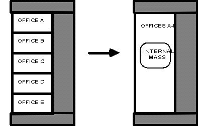
Figure 20. Representing 11 internal walls as internal mass
A five-story building has the same ceiling/floor construction separating each of the levels. Zones that are on floors 2 through 4 may be described using a single piece of internal mass to represent both the floor and ceiling. The construction for this internal mass would be identical to the ceiling/floor construction that would be used to describe separate surfaces and the area of the internal mass surface would be the total surface area of the combined ceilings/floors (i.e. twice the total floor area).
This is a unique character string associated with the internal mass surface. Though it must be unique from other surface names, it is used primarily for convenience with internal mass surfaces.
This is the name of the construction (ref: Construction) used in the surface.
This is the name of the zone in which the internal mass is represented.
This field is the surface area of the internal mass. The area that is specified must be the entire surface area that is exposed to the zone. If both sides of a wall are completely within the same zone, then the area of both sides must be included when describing that internal wall.
IDF examples of Internal Mass surfaces:
InternalMass,Zn002:IntM001, !- Surface Name
INTERIOR, !- Construction Name
DORM ROOMS AND COMMON AREAS, !- Zone
408.7734 ; !- Total area exposed to Zone {m2}
InternalMass,Zn002:IntM002, !- Surface Name
PARTITION02, !- Construction Name
DORM ROOMS AND COMMON AREAS, !- Zone
371.6122 ; !- Total area exposed to Zone {m2}
Note that Surface Outputs from specialized algorithms (such as Effective Moisture Penetration Depth (EMPD), Combined Heat and Moisture Transport (HAMT) and Conduction Finite Difference are discussed under the objects that describe the specialized inputs for these algorithms). You can access them via these links:
n Moisture Penetration Depth (EMPD) Outputs
n Conduction Finite Difference (CondFD) Outputs
n Heat and Moisture (HAMT) Outputs
Additionally, the output variables applicable to all heat transfer surfaces:
Zone,Average,Surface Inside Temperature[C]
Zone,Average,Surface Outside Temperature[C]
Zone,Average,Surface Int Adjacent Air Temperature [C]
Zone,Average,Surface Int Convection Coeff[W/m2-K]
Zone,Average,Surface Ext Convection Coeff[W/m2-K]
Zone,Average,Surface Ext Convection Heat Rate[W]
Zone,Average,Surface Ext Convection Heat Rate per Area[W/m2]
Zone,Sum,Surface Ext Convection Heat Loss to Outdoors[J]
Zone,Average,Surface Ext Thermal Radiation Heat Rate[W]
Zone,Average,Surface Ext Thermal Radiation Heat Rate per Area[W/m2]
Zone,Sum,Surface Ext Thermal Radiation Heat Loss to Outdoors[J]
Zone,Average,Surface Ext Rad To Air Coeff[W/m2-K]
Zone,Average,Surface Ext Rad To Sky Coeff[W/m2-K]
Zone,Average,Surface Ext Rad To Ground Coeff[W/m2-K]
Zone,Average,Beam Sol Amount from Ext Windows on Inside of Surface[W]
Zone,Average,Beam Sol Intensity from Ext Windows on Inside of Surface[W/m2]
Zone,Average,Beam Sol Amount from Int Windows on Inside of Surface[W]
Zone,Average,Beam Sol Intensity from Int Windows on Inside of Surface[W/m2]
Zone,Average,Initial Transmitted Diffuse Solar Absorbed on Inside of Surface[W]
Zone,Average,Initial Transmitted Diffuse Solar Transmitted Out Through Inside of Window Surface[W]
Zone,Average,Total Shortwave Radiation Absorbed on Inside of Surface[W]
Output variables applicable to all exterior heat transfer surfaces:
Zone,Average,Surface Ext Outdoor Dry Bulb [C]
Zone,Average,Surface Ext Outdoor Wet Bulb [C]
Zone,Average,Surface Ext Wind Speed [m/s]
Zone,Average,Surface Ext Sunlit Area [m2]
Zone,Average,Surface Ext Sunlit Fraction []
Zone,Average,Surface Ext Solar Incident[W/m2]
Zone,Average,Surface Ext Solar Beam Incident[W/m2]
Zone,Average,Surface Ext Solar Sky Diffuse Incident[W/m2]
Zone,Average,Surface Ext Solar Ground Diffuse Incident[W/m2]
Zone,Average,Surface Ext Diff Sol From Bm-To-Diff Refl From Ground[W/m2]
Zone,Average,Surface Ext Solar From Sky Diffuse Refl From Ground[W/m2]
Zone,Average,Surface Ext Solar From Sky Diffuse Refl From Obstructions[W/m2]
Zone,Average,Surface Ext Beam Sol From Bm-To-Bm Refl From Obstructions[W/m2] Zone,Average,Surface Ext Diff Sol From Bm-To-Diff Refl FromObstructions[W/m2]
Zone,Average,Surface Ext Solar Beam Cosine Of Incidence Angle[]
Output variables applicable to opaque heat transfer surfaces (FLOOR, WALL, ROOF, DOOR). Note – these are advanced variables – you must read the descriptions and understand before use – then you must use the Diagnostics object to allow reporting.
Zone,Average,Opaque Surface Inside Face Conduction[W]
Zone,Average,Opaque Surface Inside Face Conduction Gain[W]
Zone,Average,Opaque Surface Inside Face Conduction Loss[W]
Zone,Average,Zone Opaque Surface Inside Face Conduction Gain[W]
Zone,Average,Zone Opaque Surface Inside Face Conduction Loss[W]
Zone,Average,Opaque Surface Inside Face Beam Solar Absorbed[W]
Output variables applicable only to exterior windows and glass doors:
Zone,Average,Zone Transmitted Solar[W]
Zone,Sum,Zone Transmitted Solar Energy[J]
Zone,Average,Zone Window Heat Gain[W]
Zone,Sum,Zone Window Heat Gain Energy[J]
Zone,Average,Zone Window Heat Loss[W]
Zone,Sum,Zone Window Heat Loss Energy[J]
Zone,Average,Zone Beam Solar from Exterior Windows[W]
Zone,Sum,Zone Beam Solar from Exterior Windows Energy[J]
Zone,Average,Zone Diff Solar from Exterior Windows[W]
Zone,Sum,Zone Diff Solar from Exterior Windows Energy[J]
Zone,Average,Window Solar Absorbed:All Glass Layers[W]
Zone,Average,Total Shortwave Absorbed:All Glass Layers[W]
Zone,Sum,Window Solar Absorbed:All Glass Layers Energy[J]
Zone,Average,Window Solar Absorbed:Shading Device[W]
Zone,Average,Window Transmitted Solar[W]
Zone,Sum,Window Transmitted Solar Energy[J]
Zone,Average,Window Transmitted Beam Solar[W]
Zone,Average,Window Transmitted Beam-to-Beam Solar[W]
Zone,Average,Window Transmitted Beam-to-Diffuse Solar[W]
Zone,Sum,Window Transmitted Beam Solar Energy[J]
Zone,Sum,Window Transmitted Beam-to-Beam Solar Energy[J]
Zone,Sum,Window Transmitted Beam-to-Diffuse Solar Energy[J]
Zone,Average,Window Transmitted Diffuse Solar[W]
Zone,Sum,Window Transmitted Diffuse Solar Energy[J]
Zone,Average,Window System Solar Transmittance[]
Zone,Average,Window System Solar Absorptance[]
Zone,Average,Window System Solar Reflectance[]
Zone,Average,Window Gap Convective Heat Flow[W]
Zone,Sum,Window Gap Convective Heat Flow Energy[J]
Zone,Average,Window Heat Gain[W]
Zone,Sum,Window Heat Gain Energy[J]
Zone,Average,Window Heat Loss[W]
Zone,Sum,Window Heat Loss Energy[J]
Zone,Average,Glass Beam-Beam Solar Transmittance[]
Zone,Average,Glass Diffuse-Diffuse Solar Transmittance[]
Zone,Average,Window Calculation Iterations[]
Zone,Average,Solar Horizontal Profile Angle[degree]
Zone,Average,Solar Vertical Profile Angle[degree]
Zone,Average,Beam Solar Reflected by Outside Reveal Surfaces[W]
Zone,Average,Beam Solar Reflected by Inside Reveal Surfaces[W]
Zone,Average,Inside Glass Condensation Flag[]
Zone,Average,Inside Frame Condensation Flag[]
Zone,Average,Inside Divider Condensation Flag[]
Zone,Average,Fraction of Time Shading Device Is On[]
Zone,Average,Window Blind Slat Angle [deg]
Zone,Average,Blind Beam-Beam Solar Transmittance[]
Zone,Average,Blind Beam-Diffuse Solar Transmittance[]
Zone,Average,Blind Diffuse-Diffuse Solar Transmittance[]
Zone,Average,Blind/Glass System Beam-Beam Solar Transmittance[]
Zone,Average,Blind/Glass System Diffuse-Diffuse Solar Transmittance[]
Zone,State,Storm Window On/Off Flag[]
Zone,Average,Window Heat Gain from Frame and Divider to Zone [W]
Zone,Average,Window Frame Heat Gain [W]
Zone,Average,Window Frame Heat Loss [W]
Zone,Average,Window Divider Heat Gain [W]
Zone,Average,Window Divider Heat Loss [W]
Zone,Average,Window Frame Inside Temperature [C]
Zone,Average,Window Frame Outside Temperature [C]
Zone,Average,Window Divider Inside Temperature [C]
Zone,Average,Window Divider Outside Temperature [C]
If the user requests to display advanced report variables (e.g. see Output:Diagnostics keyword DisplayAdvancedReportVariables) the the following additional output variables are available for exterior windows and glass doors
Zone,Average,Window Convection Heat Gain from Glazing to Zone [W]
Zone,Average,Window Net Infrared Heat Gain from Glazing to Zone [W]
Zone,Average,Window Shortwave Heat Loss from Zone Back Out Window [W]
Zone,Average,Window Heat Gain from Frame and Divider to Zone [W]
Zone,Average,Window Convection Heat Gain from Gap between Shade and Glazing to Zone [W]
Zone,Average,Window Convection Heat Gain from Shade to Zone [W]
Zone,Average,Window Net Infrared Heat Gain from Shade to Zone [W]
Output variable applicable only to interior windows and glass doors:
Zone,Average, Beam Solar Transmitted Through Interior Window [W]
The inside surface temperature of a heat transfer surface.
The outside surface temperature of a heat transfer surface.
The effective bulk air temperature used for modeling the inside surface convection heat transfer. This is the same as the zone mean air temperature when using the mixing model for roomair. However, if more advanced roomair models are used, this variable will report the air temperature predicted by the roomair model as it was used in the surface heat balance model calculations.
The inside air film convective conductance for a heat transfer surface.
The rate of heat transfer from the inside face of the surface to the zone air.
The rate of heat transfer from the inside face of the surface to the zone air per unit surface area.
The heat transferred from the inside face of the surface to the zone air.
The outside air film convective conductance for a heat transfer surface.
The rate of convection heat transfer from the outside face of the surface to the outdoor air.
The rate of convection heat transfer from the outside face of the surface to the outdoor air per unit surface area.
The heat transferred from the outside face of the surface to the outdoor air by surface convection heat transfer.
The rate of thermal radiation heat transfer from the outside face of the surface to the outdoor surroundings. This is the net of all forms of longwave thermal infrared radiation heat transfer.
The rate of thermal radiation heat transfer from the outside face of the surface to the outdoor surroundings per unit area. This is the net of all forms of longwave thermal infrared radiation heat transfer.
The heat transferred from the outside face of the surface to the outdoor surroundings by all forms of surface longwave thermal infrared radiation heat transfer.
The outside heat transfer coefficient for radiation exchange with the air mass.
The outside heat transfer coefficient for radiation exchange with the sky.
The outside heat transfer coefficient for radiation exchange with the ground.
Beam solar radiation from the exterior windows in a zone incident on the inside face of a surface in the zone. If Solar Distribution in the BUILDING object is equal to MinimalShadowing or FullExterior, it is assumed that all beam solar from exterior windows falls on the floor. In this case the value of this report variable can be greater than zero only for floor surfaces. If Solar Distribution equals FullInteriorExterior the program tracks where beam solar from exterior windows falls inside the zone, in which case the value of this variable can be greater than zero for floor as well as wall surfaces.
The previous variable divided by the surface’s area.
Beam solar radiation from the interior (i.e., interzone) windows in a zone incident on the inside face of a surface in the zone. This value is calculated only if Solar Distribution in the BUILDING object is equal to FullInteriorExterior. However, the program does not track where this radiation falls. Instead, it is treated by the program as though it were diffuse radiation uniformly distributed over all of the zone surfaces. See Figure 21.
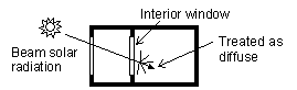
Figure 21. Beam solar radiation entering a zone through an interior window is distributed inside the zone as though it were diffuse radiation.
The previous variable divided by the surface’s area. Since this diffuse radiation is assumed to be uniformly distributed, the value of this report variable will be the same for all of the heat transfer surfaces in a zone.
As of Version 2.1, diffuse solar transmitted through exterior and interior windows is no longer uniformly distributed. Instead, it is distributed according to the approximate view factors between the transmitting window and all other heat transfer surfaces in the zone. This variable is the amount of transmitted diffuse solar that is initially absorbed on the inside of each heat transfer surface. The portion of this diffuse solar that is reflected by all surfaces in the zone is subsequently redistributed uniformly to all heat transfer surfaces in the zone, along with interior reflected beam solar and shortwave radiation from lights. The total absorbed shortwave radiation is given by the next variable.
As of Version 2.1, the previous variable plus absorbed shortwave radiation from uniformly distributed initially-reflected diffuse solar, reflected beam solar, and shortwave radiation from lights.
The outdoor air dry-bulb temperature calculated at the height above ground of the surface centroid.
The outdoor air wet-bulb temperature calculated at the height above ground of the surface centroid.
The outdoor wind speed calculated at the height above ground of the surface centroid.
The outside area of an exterior surface that is illuminated by (unreflected) beam solar radiation.
The fraction of the outside area of an exterior surface that is illuminated by (unreflected) beam solar radiation. Equals Surface Ext Sunlit Area divided by total surface area.
The total solar radiation incident on the outside of an exterior surface. It is the sum of:
Surface Ext Solar Beam Incident
Surface Ext Solar Sky Diffuse Incident
Surface Ext Solar Ground Diffuse Incident
Surface Ext Solar From Sky Diffuse Refl From Obstructions
Surface Ext Beam Sol From Bm-To-Bm Refl From Obstructions
Surface Ext Diff Sol From Bm-To-Diff Refl FromObstructions
The solar beam radiation incident on the outside of an exterior surface, including the effects of shadowing, if present. The beam here is that directly from the sun; it excludes beam specularly reflected from obstructions.
The solar diffuse radiation from the sky incident on the outside of an exterior surface, including the effects of shadowing, if present.
The solar diffuse radiation incident on the outside of an exterior surface that arises from reflection of beam solar and sky diffuse solar from the ground. This is the sum of the next two output variables, “Surface Ext Diff Sol From Bm-To-Diff Refl From Ground” and “Surface Ext Solar From Sky Diffuse Refl From Ground.” The reflected solar radiation from the ground is assumed to be diffuse and isotropic (there is no specular component).
If “Reflections” option is not chosen in the Solar Distribution Field in the BUILDING object, the effects of shadowing are accounted for by the user-specified value of View Factor to Ground for the surface. If “Reflections” option is chosen, the program determines the effects of shadowing, including time-varying shadowing of the ground plane by the building itself.
The solar diffuse radiation incident on the outside of an exterior surface that arises from beam-to-diffuse reflection from the ground. It is assumed that there is no beam-to-beam (specular) component. The beam here is that directly from the sun; it excludes beam specularly reflected from obstructions.
The solar diffuse radiation incident on the outside of an exterior surface that arises from sky diffuse solar reflection from the ground. The sky diffuse here is that directly from the sky; it excludes reflection of sky diffuse from obstructions.
The solar diffuse radiation incident on the outside of an exterior surface that arises from sky diffuse reflection from one or more obstructions. This value will be non-zero only if “Reflections” option is chosen in the BUILDING object.
The solar beam radiation incident on the outside of an exterior surface that arises from beam-to-beam (specular) reflection from one or more obstructions. This value will be non-zero only if “Reflections” option is chosen in the BUILDING object. For windows, the program treats this beam radiation as diffuse radiation in calculating its transmission and absorption.
The solar diffuse radiation incident on the outside of an exterior surface that arises from beam-to-diffuse reflection from building shades or building surfaces. This value will be non-zero only if “Reflections” option is chosen in the BUILDING object.
The cosine of the angle of incidence of (unreflected) beam solar radiation on the outside of an exterior surface. The value varies from 0.0 for beam parallel to the surface (incidence angle = 90O) to 1.0 for beam perpendicular to the surface (incidence angle = 0O). Negative values indicate the sun is behind the surface, i.e the surface does not see the sun.
This is the view factor multiplier for diffuse sky irradiance on exterior surfaces taking into account the anisotropic radiance of the sky. The diffuse sky irradiance on a surface is given by Anisotropic Sky Multipler * Diffuse Solar Irradiance.
The following variables apply only to opaque surfaces, where an opaque surface is considered here to be an exterior or interzone heat transfer surface of class FLOOR, WALL, ROOF or DOOR. Note – these are advanced variables – you must read the descriptions and understand before use – then you must use the Output:Diagnostics object to allow reporting.
The heat flow by conduction at the inside face of an opaque heat transfer surface. A positive value means that the conduction is from just inside the inside face to the inside face. A negative value means that the conduction is from the inside face into the surface.
Note that Inside Face Conduction, when positive, does not indicate the heat flow from the surface to the zone air, which is governed by the inside face convection coefficient and the difference in temperature between the inside face and the zone air.
The Opaque Surface Inside Face Conduction when that conduction is positive (see definition of Opaque Surface Inside Face Conduction).
The absolute value of the Opaque Surface Inside Face Conduction when that conduction is negative (see definition of Opaque Surface Inside Face Conduction).
The sum of the Opaque Surface Inside Face Conduction values for all opaque surfaces in a zone when that sum is positive. For example, assume a zone has six opaque surfaces with Opaque Surface Inside Face Conduction values of 100, -200, 400, 50, 150 and –300 W. Then Zone Opaque Surface Inside Face Conduction Gain = 700 - 500 = 200 W.
The absolute value of the sum of the Opaque Surface Inside Face Conduction values for all opaque surfaces in a zone when that sum is negative. For example, assume a zone has six opaque surfaces with Opaque Surface Inside Face Conduction values of -100, -200, 400,
-50, 150 and –300W. Then Zone Opaque Surface Inside Face Conduction Loss = |550 – 650| = |-100| = 100 W.
Beam solar radiation from exterior windows absorbed on the inside face of an opaque heat transfer surface. For Solar Distribution = FullInteriorAndExterior, this quantity can be non-zero for both floor and wall surfaces. Otherwise, for Solar Distribution = FullExterior or MinimalShadowing, it can be non-zero only for floor surfaces since in this case all entering beam solar is assumed to fall on the floor. Note that this variable will not be operational (have a real value) unless there are exterior windows in the zone.
The following output variables apply to subsurfaces that are windows or glass doors. These two subsurface types are called “window” here. “Exterior window” means that the base surface of the window is an exterior wall, floor, roof or ceiling (i.e., the base surface is a BuildingSurface:Detailed with OutsideFaceEnvironment = ExteriorEnvironment). “Interior window” means that the base surface of the window is an inter-zone wall, floor or ceiling. “Glass” means a transparent solid layer, usually glass, but possibly plastic or other transparent material. “Shading device” means an interior, exterior or between-glass shade or blind, or an exterior screen (only exterior windows can have a shading device).
The total Window Transmitted Solar of all the exterior windows in a zone.
The sum of the heat flow from all of the exterior windows in a zone when that sum is positive. (See definition of “heat flow” under “Window Heat Gain,” below.)
The absolute value of the sum of the heat flow from all of the exterior windows in a zone when that sum is negative.
The total exterior beam and diffuse solar radiation absorbed in all of the glass layers of an exterior window.
Window Solar Absorbed: Shading Device[W] and
Window Solar Absorbed: Shading Device Energy[J]The exterior beam and diffuse solar radiation absorbed in the shading device, if present, of an exterior window.
The amount of beam and diffuse solar radiation entering a zone through an exterior window. It is the sum of the following two variables, “Window Transmitted Beam Solar” and “Window Transmitted Diffuse Solar.”
The solar radiation transmitted by an exterior window whose source is beam solar incident on the outside of the window. For a bare window, this transmitted radiation consists of beam radiation passing through the glass (assumed transparent) and diffuse radiation from beam reflected from the outside window reveal, if present. For a window with a shade, this transmitted radiation is totally diffuse (shades are assumed to be perfect diffusers). For a window with a blind, this transmitted radiation consists of beam radiation that passes between the slats and diffuse radiation from beam-to-diffuse reflection from the slats. For a window with a screen, this value consists of direct beam radiation that is transmitted through the screen (gaps between the screen material) and diffuse radiation from beam-to-diffuse reflection from the screen material.
For each zone time step,
Window Transmitted Beam Solar = Window Transmitted Beam-to-Beam Solar + Window Transmitted Beam-to-Diffuse Solar
Window Transmitted Beam Solar Energy = Window Transmitted Beam-to-Beam Solar Energy + Window Transmitted Beam-to-Diffuse Solar Energy
The sum of the Window Transmitted Beam Solar (see definition above) from all exterior windows in a zone.
The sum of the Window Transmitted Beam Solar (see definition above) from all interior windows in a zone.
The solar radiation transmitted by an exterior window whose source is diffuse solar incident on the outside of the window. For a bare window, this transmitted radiation consists of diffuse radiation passing through the glass. For a window with a shade, this transmitted radiation is totally diffuse (shades are assumed to be perfect diffusers). For a window with a blind, this transmitted radiation consists of diffuse radiation that passes between the slats and diffuse radiation from diffuse-to-diffuse reflection from the slats. For a window with a screen, this value consists of diffuse radiation transmitted through the screen (gaps between the screen material) and diffuse radiation from diffuse-to-diffuse reflection from the screen material.
The combined beam and diffuse solar that first entered adjacent zones through exterior windows in the adjacent zones, was subsequently reflected from interior surfaces in those zones (becoming diffuse through that reflection), and was then transmitted through interior windows into the current zone.
The sum of the Window Transmitted Diffuse Solar (see definition above) from all interior windows in a zone.
Effective solar transmittance of an exterior window, including effect of shading device, if present. Equal to “Window Transmitted Solar” divided by total exterior beam plus diffuse solar radiation incident on the window (excluding frame, if present).
Effective solar absorptance of an exterior window, including effect of shading device, if present. Equal to “Window Solar Absorbed: All Glass Layers” plus “Window Solar Absorbed: Shading Device” divided by total exterior beam plus diffuse solar radiation incident on window (excluding frame, if present)
Effective solar reflectance of an exterior window, including effect of shading device, if present. Equal to: [1.0 – “Window System Solar Transmittance” – “Window System Solar Absorptance”].
For an airflow window, the forced convective heat flow from the gap through which airflow occurs. This is the heat gained (or lost) by the air from the glass surfaces (and between-glass shading device surfaces, if present) that the air comes in contact with as it flows through the gap. If the gap airflow goes to the zone indoor air, the gap convective heat flow is added to the zone load. Applicable to exterior windows only.
The total heat flow to the zone from the glazing, frame and divider of an exterior window when the total heat flow is positive.
For a window without an interior shading device, this heat flow is equal to:
[Window transmitted solar (see definition, above)]
+ [Convective heat flow to the zone from the zone side of the glazing]
+ [Net IR heat flow to the zone from zone side of the glazing]
– [Short-wave radiation from zone transmitted back out the window]
+ [Conduction to zone from window frame and divider, if present]
Here, short-wave radiation is that from lights and diffuse interior solar radiation.
For a window with an interior shading device, this heat flow is equal to:
[Window transmitted solar]
+ [Convective heat flow to the zone from the air flowing through the gap between glazing and shading device]
+ [Convective heat flow to the zone from the zone side of the shading device]
+ [Net IR heat flow to the zone from the zone side of the glazing]
+ [Net IR heat flow to the zone from the zone side of the shading device]
– [Short-wave radiation from zone transmitted back out the window]
+ [Conduction to zone from window frame and divider, if present]
The total window heat flow can also be thought of as the sum of the solar and conductive gain from the window glazing.
The absolute value of the total heat flow through an exterior window when the total heat flow is negative. (See definition of “total heat flow” under “Window Heat Gain,” above.)
The fraction of exterior beam solar radiation incident on the glass of an exterior window that is transmitted through the glass assuming that the window has no shading device. Takes into account the angle of incidence of beam solar radiation on the glass. Currently, all glass is considered to be transparent, so that incident beam solar is transmitted only as beam solar with no diffuse solar component.
The fraction of exterior diffuse solar radiation incident on the glass of an exterior window that is transmitted through the glass assuming that the window has no shading device. It is assumed that incident diffuse solar is transmitted only as diffuse with no beam component.
The number of iterations needed by the window-layer heat balance solution to converge.
For a vertical exterior window, this is an angle appropriate for calculating beam solar quantities appropriate to horizontal window elements such as horizontal reveal surfaces, horizontal frame and divider elements and horizontal slats of window blinds. It is defined as the angle between the window outward normal and the projection of the sun’s ray on the vertical plane containing the outward normal. See Figure 22.
For an exterior window of arbitrary tilt, it is defined as the angle between the window outward normal the projection of the sun’s ray on the plane that contains the outward normal and is perpendicular to the ground.
If the sun is behind the window, the horizontal profile angle is not defined and is reported as 0.0.
Note that in most texts what we call “horizontal profile angle” is called “vertical profile angle.”
For a vertical exterior window, this is an angle appropriate for calculating beam solar quantities appropriate to vertical window elements such as vertical reveal surfaces, vertical frame and divider elements and vertical slats of window blinds. It is defined as the angle between the window outward normal and the projection of the sun’s ray on the horizontal plane containing the outward normal. See Figure 22.
For an exterior window of arbitrary tilt, it is defined as the angle between the window outward normal the projection of the sun’s ray on the plane that contains the outward normal and is perpendicular to the plane defined above for Solar Horizontal Profile Angle for a window of arbitrary tilt.
If the sun is behind the window, the vertical profile angle is not defined and is reported as 0.0.
Note that in most texts what we call “vertical profile angle” is called “horizontal profile angle.”
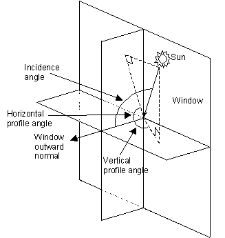
Figure 22. Vertical exterior window showing solar horizontal profile angle, solar vertical profile angle and solar incidence angle.
Beam solar radiation reflected from the outside reveal surfaces of an exterior window (ref: Reveal Surfaces under WindowProperty:FrameAndDivider).
Beam solar radiation reflected from the inside reveal surfaces of an exterior window (ref: Reveal Surfaces under WindowProperty:FrameAndDivider).
A value of 1 means that moisture condensation will occur on the innermost glass face of an exterior window (i.e., on the glass face in contact with the zone air). Otherwise the value is 0. The condition for condensation is glass inside face temperature < zone air dewpoint temperature.
For airflow exterior windows, in which forced air passes between adjacent glass faces in double- and triple-pane windows, a value of 1 means that condensation will occur on one or both of the glass faces in contact with the airflow. In this case the condition for condensation is:
n For airflow source = indoorair, temperature of either face in contact with airflow < zone air dewpoint temperature.
n For airflow source = outdoorair, temperature of either face in contact with airflow < outside air dewpoint temperature.
As for regular windows, the value will also be 1 if condensation occurs on the innermost glass face.
If an exterior window has a frame and the value of this flag is 1, condensation will occur on the inside surface of the frame. The condition for condensation is frame inside surface temperature < zone air dewpoint temperature.
If an exterior window has a divider and the value of this flag is 1, condensation will occur on the inside surface of the divider. The condition for condensation is divider inside surface temperature < zone air dewpoint temperature.
The fraction of time that a shading device is on an exterior window. For a particular simulation timestep, the value is 0.0 if the shading device is off (or there is no shading device) and the value is 1.0 if the shading device is on. (It is assumed that the shading device, if present, is either on or off for the entire timestep.) If the shading device is switchable glazing, a value of 0.0 means that the glazing is in the unswitched (light colored) state, and a value of 1.0 means that the glazing is in the switched (dark colored) state.
For a time interval longer a timestep, this is the fraction of the time interval that the shading device is on. For example, take the case where the time interval is one hour and the timestep is 10 minutes. Then if the shading device is on for two timesteps in the hour and off for the other four timesteps, then the fraction of time that the shading device is on = 2/6 = 0.3333.
For an exterior window with a blind, this is the angle in degrees between the glazing outward normal and the blind slat angle outward normal, where the outward normal points away from the front face of the slat. The slat angle varies from 0 to 180 deg. If the slat angle is 0 deg or 180 deg, the slats are parallel to the glazing and the slats are said to be “closed”. If the slat angle is 90 deg, the slats are perpendicular to the glazing and the slats are said to be “fully open”. See illustrations under WindowMaterial:Blind. For blinds with a fixed slat angle, the value reported here will be constant.
For an exterior window with a blind, this is the fraction of exterior beam solar radiation incident on the blind that is transmitted through the blind as beam solar radiation when the blind is isolated (i.e., as though the window glass were not present). Depends on various factors, including slat angle, width, separation, and thickness, and horizontal solar profile angle (for blinds with horizontal slats) or vertical solar profile angle (for blinds with vertical slats). The transmittance value reported here will be non-zero only when some beam solar can pass through the blind without hitting the slats.
For an exterior window with a blind, the fraction of exterior beam solar radiation incident on the blind that is transmitted through the blind as diffuse solar radiation when the blind is isolated (i.e., as though the window glass were not present). Depends on various factors, including slat angle, width, separation, thickness and reflectance, and horizontal solar profile angle (for blinds with horizontal slats) or vertical solar profile angle (for blinds with vertical slats).
For an exterior window with a blind, the fraction of exterior diffuse solar radiation incident on the blind that is transmitted through the blind as diffuse solar radiation when the blind is isolated (i.e., as though the window glass were not present). Depends on various factors, including slat angle, width, separation, thickness and reflectance. For blinds with a fixed slat angle the transmittance value reported here will be constant.
The fraction of exterior beam solar radiation incident on an exterior window with a blind (excluding window frame, if present) that is transmitted through the blind/glass system as beam solar radiation. Depends on various factors, including type of glass; solar incidence angle; slat angle, width, separation, and thickness; and horizontal solar profile angle (for blinds with horizontal slats) or vertical solar profile angle (for blinds with vertical slats).
The fraction of exterior diffuse solar radiation incident on an exterior window with a blind (excluding window frame, if present) that is transmitted through the blind/glass system as diffuse solar radiation. Depends on various factors, including type of glass and slat angle, width, separation, thickness and reflectance. For blinds with a fixed slat angle the transmittance value reported here will be constant.
For an exterior window with a screen, this is the fraction of exterior beam solar radiation incident on the screen that is transmitted through the screen as beam solar radiation when the screen is isolated (i.e., as though the window glass were not present). Depends on various factors, including the screen reflectance and the relative angle of the incident beam with respect to the screen. This value will include the amount of inward reflection of solar beam off the screen material surface if the user specifies this modeling option (i.e., Material: WindowScreen, field Reflected Beam Transmittance Accounting Method = Model as Direct Beam).
For an exterior window with a screen, the fraction of exterior beam solar radiation incident on the screen that is transmitted through the screen as diffuse solar radiation when the screen is isolated (i.e., as though the window glass were not present). Depends on various factors, including the screen reflectance and the relative angle of the incident beam with respect to the screen. This value is the amount of inward reflection of solar beam off the screen material surface if the user specifies this modeling option (i.e., Material: WindowScreen, field Reflected Beam Transmittance Accounting Method = Model as Diffuse); otherwise, this value will be zero.
For an exterior window with a screen, the fraction of exterior diffuse solar radiation incident on the screen that is transmitted through the screen as diffuse solar radiation when the screen is isolated (i.e., as though the window glass were not present). Depends on various factors including screen material geometry and reflectance. This value is calculated as an average, constant For a window with a screen, this value consists of diffuse radiation transmitted through the screen (gaps between the screen material) and diffuse radiation from diffuse-to-diffuse reflection from the screen material. For a window with a screen, this value consists of diffuse radiation transmitted through the screen (gaps between the screen material) and diffuse radiation from diffuse-to-diffuse reflection from the screen material.
The fraction of exterior beam solar radiation incident on an exterior window with a screen (excluding window frame, if present) that is transmitted through the screen/glass system as beam solar radiation. Depends on various factors, including the screen reflectance and the relative angle of the incident beam with respect to the screen. This value will include the amount of inward reflection of solar beam off the screen material surface if the user specifies this modeling option (i.e., Material: WindowScreen, field Reflected Beam Transmittance Accounting Method = Model as Direct Beam).
The fraction of exterior diffuse solar radiation incident on an exterior window with a screen (excluding window frame, if present) that is transmitted through the screen/glass system as diffuse solar radiation. Depends on various factors including screen material geometry and reflectance.
The beam solar radiation transmitted through an interior window. Calculated only if Solar Distribution = FullInteriorAndExterior in your Building input. The origin of this radiation is beam solar that enters through an exterior window in a zone and then passes through an interior window into the adjacent zone. The amount of this radiation depends on several factors, including sun position, intensity of beam solar incident on the exterior window (including effects of shadowing, if present), relative position of the exterior and interior window, and the size and transmittance of the windows. Note that if there are two or more exterior windows in a zone, then beam solar from one or more of them may pass through the same interior window. Likewise, if there are more than two or more interior windows in a zone then beam solar from a single exterior window may pass through one or more of the interior windows.
Indicates whether a storm window glass layer is present (ref: StormWindow). The value is 0 if the storm window glass layer is off, 1 if it is on, and –1 if the window does not have an associated storm window. Applicable only to exterior windows and glass doors.
As of Version 2.1, the diffuse solar transmitted through exterior windows that is initially distributed to another window in the zone and transmitted out of the zone through that window. For exterior windows, this transmitted diffuse solar is “lost” to the exterior environment For interior windows, this transmitted diffuse solar is distributed to heat transfer surfaces in the adjacent zone, and is part of the Initial Transmitted Diffuse Solar Absorbed on Inside of Surface for these adjacent zone surfaces.
The following output variables for windows or glass doors are available when the user requests to display advanced report variables. These seven reports show the individual components that are combined to determine overall Window Heat Gain and/or Window Heat Loss (described above).
The surface convection heat transfer from the glazing to the zone in watts. This report variable is the term called “[Convective heat flow to the zone from the zone side of the glazing]” under the description above for Window Heat Gain report variable. If the window has an interior shade or blind, then this is zero and the glazing’s convection is included in the report called “Window Convection Heat Gain from Gap between Shade and Glazing to Zone”.
The net exchange of infrared radiation heat transfer from the glazing to the zone in watts. This report variable is the term called “[Net IR heat flow to the zone from zone side of the glazing]” under the description above for Window Heat Gain report variable.
This is the short-wave radiation heat transfer from the zone back out the window in watts. This is a measure of the diffuse short-wave light (from reflected solar and electric lighting) that leave the zone through the window. This report variable is the term called “[Short-wave radiation from zone transmitted back out the window]” under the description above for Window Heat Gain report variable.
This is the heat transfer from any frames and/or dividers to the zone in watts. This report variable is the term called “[Conduction to zone from window frame and divider, if present]” under the description above for Window Heat Gain report variable. (The word “conduction” here is used because the models is simplified compared to the complexities of surface convection and radiation.)
This is the positive heat flow from window frames to the zone in watts. This is part of the Window Heat Gain from Frame and Divider to Zone.
This is the negative heat flow from window frames to the zone in watts. This is part of the Window Heat Gain from Frame and Divider to Zone.
This is the temperature of the inside surface of the window frames.
This is the temperature of the outside surface of the window frames.
This is the positive heat flow from window dividers to the zone in watts. This is part of the Window Heat Gain from Frame and Divider to Zone.
This is the negative heat flow from window dividers to the zone in watts. This is part of the Window Heat Gain from Frame and Divider to Zone.
This is the temperature of the inside surface of the window dividers.
This is the temperature of the outside surface of the window dividers.
This is the convection surface heat transfer from the both the glazing and the shade’s back face to the zone in Watts. This report variable is the term called “[Convective heat flow to the zone from the air flowing through the gap between glazing and shading device]” under the description above for Window Heat Gain report variable.
This is the convection surface heat transfer from the front side of any interior shade or blind to the zone in Watts. This report variable is the term called “[Convective heat flow to the zone from the zone side of the shading device]” under the description above for Window Heat Gain report variable.
The net exchange of infrared radiation heat transfer from the shade or blind to the zone in watts. This report variable is the term called “[Net IR heat flow to the zone from the zone side of the shading device]” under the description above for Window Heat Gain report variable.
The temperature of the TC glass layer of a TC window at each time step.
The temperature under which the optical data of the TC glass layer are specified.
The overall properties (U-factor/SHGC/VT) of the thermochromic windows at different specification temperatures are reported in the .eio file. These window constructions are created by EnergyPlus during run time. They have similar names with suffix “_TC_XX” where XX represents a specification temperature.
The switching factor (tint level) of the switchable window: 0 means no switching – clear state; 1 means fully switched – dark state.
The visible transmittance of the switchable window.
Several reports can be selected for Surfaces. (See Group – Report for details on how to specify). Examples are:
This report produces a special file (eplusout.dxf) in the industry standard DXF (Drawing Interchange Format) for drawings. It is produced and accepted by many popular, commercial CAD programs. Detailed reference can be found on the AutoCAD™ website at: http://www.autodesk.com/techpubs/autocad/acadr14/dxf/index.htm
EnergyPlus produces this file from the Report command:
Output:Reports, Surfaces, DXF;
This version of the report creates lines in the eplusout.eio file for each surface (except internal mass surfaces). Details of this reporting is shown in the Output Details and Examples document.
Shading surfaces are entities outside of the building that may cast shadows on the building’s heat transfer surfaces. These entities do not typically have enough thermal mass to be described as part of the building’s thermal makeup.
The most important effect of shading surfaces is to reduce solar gain in windows that are shadowed. (However, in some cases, shading surfaces can reflect solar onto a wall or window and increase solar gain.)
There are two kinds of shading surfaces in EnergyPlus: detached and attached. A detached shading surface, such as a tree or neighboring building, is not connected to the building. An attached shading surface is typically an overhang or fin that is attached to a particular base surface of the building, usually a wall; attached shading surfaces are usually designed to shade specific windows.
Objects for detached shading surfaces:
Shading:Site
Shading:Building
Shading:Site:Detailed
Shading:Building:Detailed
Similarly to the surfaces, the detailed objects use vertex entry whereas the other objects are limited to rectangular representation.
Objects for attached shading surfaces:
Shading:Overhang
Shading:Overhang:Projection
Shading:Fin
Shading:Fin:Projection
Shading:Zone:Detailed
EnergyPlus creates “bi-directional” shades from each shading surface entered. This means that the shade you input will cast a shadow no matter which side of the shade the sun is on. For example, a vertical fin will cast a shadow whether the sun is on the left side or right side of the fin.[5]
It is important to note that EnergyPlus will automatically account for “self-shading” effects—such as in L-shaped buildings—in which some of the building’s wall and roof surfaces shade other parts of the building, especially windows. This means that you only need to describe shading elements that aren’t building heat-transfer surfaces.
Shading surfaces can also reflect solar radiation onto the building. This feature is simulated if you choose FullExteriorWithReflections or FullInteriorAndExteriorWithReflections in the Building object (ref: Building - Field: Solar Distribution). In this case, you specify the reflectance properties of a shading surface with the ShadingProperty:Reflectance object .
Shading surfaces also automatically shade diffuse solar radiation (and long-wave radiation) from the sky. And they will automically shade diffuse solar radiation from the ground if Solar Distribution Field = FullExteriorWithReflections or FullInteriorAndExteriorWithReflections in the Building object.[6] Otherwise, shading surfaces will not shade diffuse radiation from the ground unless you enter a reduced value for View Factor to Ground for those building surfaces that are shaded (ref: BuildingSurface:Detailed - Field: View Factor to Ground and FenestrationSurface:Detailed - Field: View Factor to Ground).
These objects are used to describe rectangular shading elements that are external to the building. Examples are trees, high fences, near-by hills, and neighboring buildings.
If relative coordinates are used (ref: Field: Coordinate System in GlobalGeometryRules), shading surfaces entered with Shading:Site remain stationary if the building is rotated, whereas those entered with Shading:Building rotate with the building. If world coordinates are used Shading:Site and Shading:Building are equivalent.
These shading elements are always opaque.
This is a unique character string associated with the detached shading surface. Though it must be unique from other surface names, it is used primarily for convenience with detached shading surfaces.
Theoretically, this should face to the surface it is shading (i.e. if a south wall, this should be a north facing shade) but since EnergyPlus automatically generates the mirror image, the facing angle per se’ is not so important.
The tilt angle is the angle (in degrees) that the shade is tilted from horizontal (or the ground). Default for this field is 90 degrees.
The rectangular surfaces specify the lower left corner of the surface for their starting coordinate. See the introductory paragraph for rules on this entry.
This field is the X coordinate (in meters).
This field is the Y coordinate (in meters).
This field is the Z coordinate (in meters).
This field is the length of the shade in meters.
This field is the width of the shade in meters.
Examples of these (can be found in example files 4ZoneWithShading_Simple_1.idf and 4ZoneWithShading_Simple_2.idf)
Shading:Building,
Bushes-East, !- Name
90, !- Azimuth Angle {deg}
90, !- Tilt Angle {deg}
45, !- Starting X Coordinate {m}
0, !- Starting Y Coordinate {m}
0, !- Starting Z Coordinate {m}
50, !- Length {m}
1; !- Height {m}
Shading:Site,
Bushes-North, !- Name
0, !- Azimuth Angle {deg}
90, !- Tilt Angle {deg}
45, !- Starting X Coordinate {m}
50, !- Starting Y Coordinate {m}
0, !- Starting Z Coordinate {m}
50, !- Length {m}
1; !- Height {m}
These objects are used to describe shading elements that are external to the building. Examples are trees, high fences, near-by hills, and neighboring buildings.
If relative coordinates are used (ref: Field: Coordinate System in GlobalGeometryRules), shading surfaces entered with Shading:Site:Detailed remain stationary if the building is rotated, whereas those entered with Shading:Building:Detailed rotate with the building. If world coordinates are used Shading:Site:Detailed and Shading:Building:Detailed are equivalent.
While "detached" implies that shading surfaces are not part of the building, the detached shading sequence can be used to describe attached shading surfaces that may shade heat transfer surfaces in more than one zone. For example, wing A of a building might shade several zones of wing B but wing A (for whatever reason) is not described in the geometry for the simulation so it is represented by a detached shade to get its shadowing effect.
This is a unique character string associated with the detached shading surface. Though it must be unique from other surface names, it is used primarily for convenience with detached shading surfaces.
The name of a schedule of solar transmittance values from 0.0 to 1.0 for the shading surface. If a blank is entered in this field, the transmittance value defaults to 0.0, i.e., the shading surface is opaque at all times. This scheduling can be used to allow for seasonal transmittance change, such as for deciduous trees that have a higher transmittance in winter than in summer. Transmittance based on time of day can also be used—a movable awning, for example, where the transmittance is some value less than 1.0 when the awning is in place and is 1.0 when the awning is retracted.
The following assumptions are made in the shading surface transmittance calculation:
n Both sides of the shading surface have the same transmittance properties.
n The transmittance is the same for both beam and diffuse solar radiation.
n Beam solar transmittance is independent of angle of incidence on the shading surface.
n Beam radiation incident on a shading surface is transmitted as beam radiation with no change in direction, i.e., there is no beam-to-diffuse component.
n If two shading surfaces with non-zero transmittance overlap, the net transmittance is the product of the individual transmittances. Inter-reflection between the shading surfaces (and between the shading surfaces and the building) is ignored.
n For the daylighting calculation (ref: Group – Daylighting) the shading surface’s visible transmittance is assumed to be the same as its solar transmittance.
n Shading devices are assumed to be opaque to long-wave radiation no matter what the solar transmittance value is.
Note that shading devices only shade solar radiation when the sun is up, which is automatically determined by EnergyPlus from latitude, time of year, etc. The user need only account for the time-varying transmittance of the shading device in the transmittance schedule, not whether the sun is up or not.
The number of sides in the surface (number of X,Y,Z vertex groups). For further information, see the discussion on “Surface Vertices” above.
IDF example of Detached Shading Surfaces:
Shading:Building:Detailed,
EAST SIDE TREE, !- Detached Shading
ShadingTransmittance:0002, !- Shadowing Transmittance & Schedule
3, !-Triangle
33.52800 , 10.66800 , 10.05800 ,
33.52800 , 13.71600 , 0.9140000 ,
33.52800 , 4.572000 , 0.9140000 ;
Shading:Building:Detailed,
WEST SIDE TREE, !- Detached Shading
ShadingTransmittance:0002, !- Shadowing Transmittance & Schedule
3, !-Triangle
-3.048000 , 7.620000 , 10.05800 ,
-3.048000 , 4.572000 , 0.9140000 ,
-3.048000 , 13.71600 , 0.9140000 ;
Overhangs are usually horizontal devices that are used to shade windows. Fins are usually vertical devices that similarly shade windows.
An overhang typically is used to shade a window in a building.
This is the name of the overhang. It must be different from other surface names.
The name of a window or door that this overhang shades.
This field is the height (meters) above the top of the door for the overhang.
This field is the tilt angle from the Window/Door. For a flat overhang, this would be 90 (degrees).
This field is the width from the left edge of the window/door to the start of the overhang (meters).
This field is the width from the right edge of the window/door to the start of the overhang (meters).
This field is the depth of the overhang (meters) projecting out from the wall.
An overhang typically is used to shade a window in a building. This object allows for specifying the depth of the overhang as a fraction of the window or door’s height.
This is the name of the overhang. It must be different from other surface names.
The name of a window or door that this overhang shades.
This field is the height (meters) above the top of the door for the overhang.
This field is the tilt angle from the Window/Door. For a flat overhang, this would be 90 (degrees).
This field is the width from the left edge of the window/door to the start of the overhang (meters).
This field is the width from the right edge of the window/door to the start of the overhang (meters).
This field is the fraction of the window/door height to specify as the depth of the overhang (meters) projecting out from the wall.
Fins shade either side of windows/doors in a building. This object allows for specification of both fins for the window. Fin placement is relative to the edge of the glass and user must include the frame width when a frame is present.
This is the name of the overhang. It must be different from other surface names.
The name of a window or door that this overhang shades.
This field is the width from the left edge of the window/door to the plane of the left fin (meters). The extension width is relative to the edge of the glass and includes the frame width when a frame is present.
This field is the distance from the top of the window to the top of the left fin (meters) and is relative to the edge of the glass and includes the frame width when a frame is present.
This field is the distance from the bottom of the window to the bottom of the left fin (meters) and is relative to the edge of the glass and includes the frame width when a frame is present.
This field is the tilt angle from the window / door for the left fin. Typically, a fin is 90 degrees (default) from its associated window/door.
This field is the depth (meters) of the left fin (projecting out from the wall).
This field is the width from the right edge of the window/door to the plane of the right fin (meters). The extension width is relative to the edge of the glass and includes the frame width when a frame is present.
This field is the distance from the top of the window to the top of the right fin (meters) and is relative to the edge of the glass and includes the frame width when a frame is present.
This field is the distance from the bottom of the window to the bottom of the right fin (meters) and is relative to the edge of the glass and includes the frame width.
This field is the tilt angle from the window / door for the right fin.. Typically, a fin is 90 degrees (default) from its associated window/door.
This field is the depth (meters) of the right fin (projecting out from the wall).
Fins shade either side of windows/doors in a building. This object allows for specification of both fins for the window. This object allows for specifying the depth of the overhang as a fraction of the window or door’s width. Fin placement is relative to the edge of the glass and user must include the frame width when a frame is present.
This is the name of the overhang. It must be different from other surface names.
The name of a window or door that this overhang shades.
This field is the width from the left edge of the window/door to the plane of the left fin (meters). The extension width is relative to the edge of the glass and includes the frame width when a frame is present.
This field is the distance from the top of the window to the top of the left fin (meters) and is relative to the edge of the glass and includes the frame width when a frame is present.
This field is the distance from the bottom of the window to the bottom of the left fin (meters) and is relative to the edge of the glass and includes the frame width when a frame is present.
This field is the tilt angle from the window / door for the left fin. Typically, a fin is 90 degrees (default) from its associated window/door.
This field is the fraction of the window/door width to specify as the depth of the left fin (meters) projecting out from the wall.
This field is the width from the right edge of the window/door to the plane of the right fin (meters).. The extension width is relative to the edge of the glass and includes the frame width when a frame is present.
This field is the distance from the top of the window to the top of the right fin (meters) and is relative to the edge of the glass and includes the frame width when a frame is present.
This field is the distance from the bottom of the window to the bottom of the right fin (meters) and is relative to the edge of the glass and includes the frame width when a frame is present.
This field is the tilt angle from the window / door for the right fin.. Typically, a fin is 90 degrees (default) from its associated window/door.
This field is the fraction of the window/door width to specify as the depth of the right fin (meters) projecting out from the wall.
zone.
Examples of these (can be found in example files 4ZoneWithShading_Simple_1.idf and 4ZoneWithShading_Simple_2.idf)
Shading:Overhang:Projection,
Zn001:Wall001:Win001:Shade001, !- Name
Zn001:Wall001:Win001, !- Window or Door Name
.7, !- Height above Window or Door {m}
90, !- Tilt Angle from Window/Door {deg}
.2, !- Left extension from Window/Door Width {m}
.2, !- Right extension from Window/Door Width {m}
.6; !- Depth as Fraction of Window/Door Height {m}
Shading:Overhang,
Zn001:Wall001:Door001:Shade001, !- Name
Zn001:Wall001:Door001, !- Window or Door Name
.6, !- Height above Window or Door {m}
90, !- Tilt Angle from Window/Door {deg}
0, !- Left extension from Window/Door Width {m}
0, !- Right extension from Window/Door Width {m}
3; !- Depth {m}
Shading:Fin:Projection,
Zn001:Wall001:Shade003, !- Name
Zn001:Wall001:Win001, !- Window or Door Name
.1, !- Left Extension from Window/Door {m}
.1, !- Left Distance Above Top of Window {m}
.1, !- Left Distance Below Bottom of Window {m}
90, !- Left Tilt Angle from Window/Door {deg}
.6, !- Left Depth as Fraction of Window/Door Width {m}
.1, !- Right Extension from Window/Door {m}
.1, !- Right Distance Above Top of Window {m}
.1, !- Right Distance Below Bottom of Window {m}
90, !- Right Tilt Angle from Window/Door {deg}
.6; !- Right Depth as Fraction of Window/Door Width {m}
This object is used to describe attached “subsurfaces” such as overhangs, wings or fins that project outward from a base surface. This classification is used for convenience; actually, a device of this type can cast shadows on the surface to which it is attached as well as on adjacent surfaces. For example, a fin may shade its parent wall as well as adjacent walls.
Note that a zone surface can cast shadows on other zone surfaces. However, you don’t have to worry about such effects—for example, one wall of an L-shaped building shading another wall--because EnergyPlus will automatically check for this kind of “self shadowing” and do the proper calculations.
Unlike attached (or detached) shading surfaces, building surfaces can only cast shadows in the hemisphere towards which they face. This means, for example, that a roof that faces upward will not cast a shadow downward. (Thus, specifying an oversized roof in an attempt to account for the shading effects of overhangs will not work). Interior surfaces do not cast shadows of any kind.
This is the name of the attached shading surface. It must be different from other surface names.
This is the name of the surface to which this shading device is attached. This surface can be a wall (or roof) but not a window or door.
The name of a schedule of solar transmittance values from 0.0 to 1.0 for the shading surface. If a blank is entered in this field, the transmittance value defaults to 0.0, i.e., the shading surface is opaque at all times. This scheduling can be used to allow for seasonal transmittance change, such as for deciduous trees that have a higher transmittance in winter than in summer. Transmittance based on time of day can also be used—a movable awning, for example, where the transmittance is some value less than 1.0 when the awning is in place and is 1.0 when the awning is retracted.
The following assumptions are made in the shading surface transmittance calculation:
n Both sides of the shading surface have the same transmittance properties.
n The transmittance is the same for both beam and diffuse solar radiation.
n Beam solar transmittance is independent of angle of incidence on the shading surface.
n Beam radiation incident on a shading surface is transmitted as beam radiation with no change in direction, i.e., there is no beam-to-diffuse component.
n If two shading surfaces with non-zero transmittance overlap, the net transmittance is the product of the individual transmittances. Inter-reflection between the shading surfaces (and between the shading surfaces and the building) is ignored.
n For the daylighting calculation (ref: Group – Daylighting) the shading surface’s visible transmittance is assumed to be the same as its solar transmittance.
n Shading devices are assumed to be opaque to long-wave radiation no matter what the solar transmittance value is.
Note that shading devices only shade solar radiation when the sun is up, which is automatically determined by EnergyPlus from latitude, time of year, etc. The user need only account for the time-varying transmittance of the shading device in the transmittance schedule, not whether the sun is up or not.
The number of sides in the surface (number of X,Y,Z vertex groups). For further information, see the discussion on “Surface Vertices” above. The example below shows the correct input for an overhang (to shade the appropriate portion of the base wall and window).
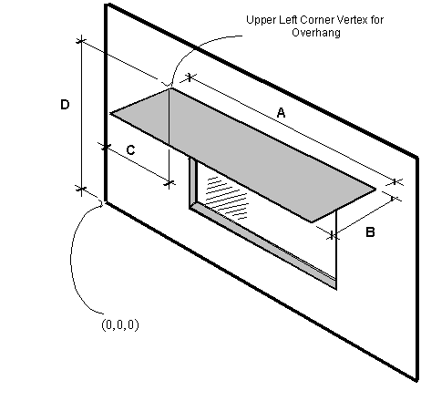
Figure 23. Illustration for Attached Shading Surface
Proper specification for this overhang (facing up) is:
4,(C,0,D),(C,-B,D),(C+A,-B,D),(C+A,0,D); () used to illustrate each vertex.
Note that for horizontal surfaces, any corner may be chosen as the starting corner. The order of vertices determines whether the surface is facing up or down. Shading surfaces are mirrored automatically unless the user specifies "DoNotMirrorDetachedShading", so each shading surface need only be described once.
Thus, another shading surface will be created (facing down):
4,(C+A,-B,D),(C+A,0,D),(C,0,D),(C,-B,D);
IDF example of attached shading surfaces (overhang, fin):
Shading:Zone:Detailed,
Zn001:Wall001:Shade001, !- Surface Name
Zn001:Wall001, !- Base Surface Name
ShadingTransmittance:0001, !- Shadowing Transmittance Schedule
4, !-RectangularOverhang
1.524000 , -0.3050000 , 2.865000 ,
1.524000 , 0.0000000E+00, 2.865000 ,
4.572000 , 0.0000000E+00, 2.865000 ,
4.572000 , -0.3050000 , 2.865000 ;
Shading:Zone:Detailed,
Zn003:Wall001:Shade001, !- Surface Name
Zn003:Wall001, !- Base Surface Name
ShadingTransmittance:0001, !- Shadowing Transmittance Schedule
4, !-RectangularLeftFin
57.97000 , 8.450000 , 10.00000 ,
57.97000 , 8.450000 , 0.0000000E+00,
57.97000 , 6.450000 , 0.0000000E+00,
57.97000 , 6.450000 , 10.00000 ;
Shading:Zone:Detailed,Zn003:Wall001:Shade002, !- Surface Name
Zn003:Wall001, !- Base Surface Name
ShadingTransmittance:0003, !- Shadowing Transmittance Schedule
4, !-RectangularRightFin
77.97000 , 6.450000 , 10.00000 ,
77.97000 , 6.450000 , 0.0000000E+00,
77.97000 , 8.450000 , 0.0000000E+00,
77.97000 , 8.450000 , 10.00000 ;
Specifies the reflectance properties of a shading surface when the solar reflection calculation has requested, i.e., when if “Reflections” option is chosen in the Building object (ref: Building - Field: Solar Distribution). It is assumed that shading surfaces are divided into an unglazed, diffusely reflecting portion and a glazed, specularly-reflecting portion, either of which may be zero. The reflectance properties are assumed to be the same on both sides of the shading surface.
Note that a shadowing transmittance schedule (ref: Shading Surfaces, Field: Transmittance Schedule Name) can be used with a reflective shading surface. However, EnergyPlus assumes that the reflectance properties of the shading surface are constant even if the transmittance varies.
The name of the Shading:Site:Detailed, Shading:Building:Detailed, or Shading:Zone:Detailed object to which the following fields apply.
If this ShadingProperty:Reflectance object is not defined for a shading surface the default values listed in each of the following fields will be used in the solar reflection calculation.
The diffuse solar reflectance of the unglazed part of the shading surface (default = 0.2). This reflectance is assumed to be the same for beam-to-diffuse and diffuse-to-diffuse reflection. Beam-to-diffuse reflection is assumed to be independent of angle of incidence of beam radiation. Diffuse-to-diffuse reflection is assumed to be independent of angular distribution of the incident of diffuse radiation. The outgoing diffuse radiation is assumed to be isotropic (hemispherically uniform).
The sum of this reflectance and the shading surface transmittance should be less than or equal to 1.0.
The diffuse visible reflectance of the unglazed part of the shading surface (default = 0.2). This reflectance is assumed to be the same for beam-to-diffuse and diffuse-to-diffuse reflection. Beam-to-diffuse reflection is assumed to be independent of angle of incidence of beam radiation. Diffuse-to-diffuse reflection is assumed to be independent of angular distribution of the incident of diffuse radiation. The outgoing diffuse radiation is assumed to be isotropic (hemispherically uniform).
This value if used only for the daylighting calculation (ref: Daylighting:Controls). The sum of this reflectance and the shading surface transmittance should be less than or equal to 1.0.
The fraction of the area of the shading surface that consists of windows (default = 0.0). It is assumed that the windows are evenly distributed over the surface and have the same glazing construction (see following “Name of Glazing Construction”). This might be the case, for example, for reflection from the façade of a neighboring, highly-glazed building. For the reflection calculation the possible presence of shades, screens or blinds on the windows of the shading surface is ignored. Beam-to-beam (specular) reflection is assumed to occur only from the glazed portion of the shading surface. This reflection depends on angle of incidence as determined by the program from the glazing construction. Beam-to-diffuse reflection from the glazed portion is assumed to be zero. The diffuse-to-diffuse reflectance of the glazed portion is determined by the program from the glazing construction.
The name of the construction of the windows on the shading surface. Required if Fraction of Shading Surface That Is Glazed is greater than 0.0.
IDF example of Shading Surface Reflectance for shading surface with specular reflection
Shading:Site:Detailed,
Adjacent Glazed Facade, !- User Supplied Surface Name
, !- Shadowing Transmittance Schedule
4, !- Number of Surface Vertex Groups -- Number of (X,Y,Z) groups
0,-24,30, !- Vertex 1 X,Y,Z coordinates
0,-24,0, !- Vertex 2 X,Y,Z coordinates
0,0,0, !- Vertex 3 X,Y,Z coordinates
0,0,30; !- Vertex 3 X,Y,Z coordinates
ShadingProperty:Reflectance,
Adjacent Glazed Facade, !- Name of Surface:Shading Object
0.3, !- Diffuse Solar Reflectance of Unglazed Part of Shading Surface
0.3, !- Diffuse Visible Reflectance of Unglazed Part of Shading Surface
0.7, !- Fraction of Shading Surface That Is Glazed
GlassCon-1; !- Name of Glazing Construction
IDF example of Shading Surface Reflectance for shading surface without specular reflection
Shading:Site:Detailed,
Adjacent Blank Facade, !- User Supplied Surface Name
, !- Shadowing Transmittance Schedule
4, !- Number of Surface Vertex Groups -- Number of (X,Y,Z) groups
0,-24,30,
0,-24,0,
0,0,0,
0,0,30;
ShadingProperty:Reflectance,
Adjacent Blank Facade, !- Name of Surface:Shading Object
0.4, !- Diffuse Solar Reflectance of Unglazed Part of Shading Surface
0.4, !- Diffuse Visible Reflectance of Unglazed Part of Shading Surface
0.0, !- Fraction of Shading Surface That Is Glazed
; !- Name of glazing construction
Window shading with coverings like drapes, blinds, screens or pull-down shades can be used to reduce the amount of solar radiation entering the window or reduce daylighting glare. It can also be used to reduce heat loss through the window (movable insulation). Leaving the window covering open in the winter can maximize solar heat gain and thereby reduce heating loads.
With WindowProperty:ShadingControl—which is referenced by windows and glass doors (ref: FenestrationSurface:Detailed with Type = Window or GlassDoor)--you specify the type and location of the shading device, what variable or combination of variables controls deployment of the shading device, and what the control setpoint is. If the shading device is a blind, you also specify how the slat angle is controlled.
As shown in Figure 24, a shading device can be inside the window (Shading Type = InteriorShade or InteriorBlind), outside the window (Shading Type = ExteriorShade or ExteriorBlind), or between panes of glass (Shading Type = BetweenGlassShade or BetweenGlassBlind). The exception is window screens which can only be outside the window (Shading Type = ExteriorScreen).
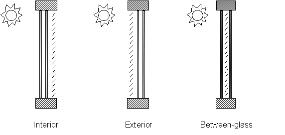
Figure 24. Allowed locations of a window shading device.
When a shading device is present it is either retracted or activated. When it is retracted it covers none of the window. When it is activated it covers the entire glazed part of the window (but not the frame). Whether the shading device is retracted or activated in a particular timestep depends on the control mechanism: see “Shading Control Type,” below. To model a case in which the shading device, when activated, covers only part of the window you will have to divide the window into two separate windows, one with the shading device and one without the shading device.
A shading device can also be of a kind in which the optical properties of the glazing switch from one set of values to another in order to increase or decrease solar or visible transmittance (Shading Type = SwitchableGlazing).
There are two ways of specifying the actual shading device:
This is the name of a window Construction that has the shading device as one of its layers. The thermal and solar-optical properties of the shading device are given by the shading material referenced in that Construction (ref: Construction, WindowMaterial:Shade, WindowMaterial:Screen and WindowMaterial:Blind). To use this method you have to define two Constructions for the window, one without the shading device and one with it. See Example 1, below.
The Construction without the shading device is referenced in the FenestrationSurface:Detailed input for the window (see IDF example, below). The Construction with the shading device is referenced by the window’s WindowProperty:ShadingControl.
For Shading Type = InteriorShade, InteriorBlind, ExteriorShade, ExteriorScreen and ExteriorBlind these two Constructions must be identical expect for the presence of the shading layer in the shaded Construction, otherwise you will get an error message. You will also get an error message if the Construction referenced by the window has a shading layer.
This is the name of a WindowMaterial:Shade, WindowMaterial:Screen or WindowMaterial:Blind. This method can be used with Shading Type = InteriorShade, InteriorBlind, ExteriorShade and ExteriorBlind. It cannot be used with Shading Type = BetweenGlassShade, BetweenGlassBlind, or SwitchableGlazing. If Shading Type = InteriorShade or ExteriorShade, then you specify the name of a WindowMaterial:Shade. If Shading Type = InteriorBlind or ExteriorBlind, then you specify the name of a WindowMaterial:Blind. If Shading Type = ExteriorScreen, then you specify the name of a WindowMaterial:Screen. See Example 2, below. This method is simpler to use since you don’t have to specify two Constructions that differ only by the shading layer.
When this method is used, the program will automatically create a shaded window construction by adding a shading layer to the outside or inside of the construction corresponding to the window referencing the WindowProperty:ShadingControl. The name, created by the program, of this shaded construction is composed as follows: if the name of the window construction is CCC and the material name of the shading device is DDD, then the shaded construction name is CCC:DDD:INT for an interior shading device and CCC:DDD:EXT for an exterior shading device.
This method is the required if you want to add a shading device to a construction brought in from a WINDOW5 Data File (ref: Construction:WindowDataFile).
Note that if both “Name of Construction with Shading” and “Material Name of Shading Device” are specified, the former takes precedence.
Most Shading Control Types allow you to specify a schedule that determines when the control is active. One example is a control that is active seasonally. For example, to deploy shading only in the summer when the incident solar is high enough, use Shading Control Type = OnIfHighSolarOnWindow with a schedule that is 1 during the summer months and 0 otherwise and specify Shading Control Is Scheduled = YES.
In addition, most Shading Control Types also allow you to specify that glare control is active in addition to the specified Control Type. For example, you might want to deploy shading when the solar incident on a window is too high OR the glare from the window is too high. This type of joint control requires that the window be in a daylit zone, that the maximum allowed glare be specified in the Daylighting object for the zone, and that Glare Control Is Active = YES in WindowProperty:ShadingControl.
If Shading Type = InteriorBlind, ExteriorBlind or BetweenGlassBlind you can use WindowProperty:ShadingControl to specify how the slat angle of the blind is controlled when the blind is in place.
A special type of WindowProperty:ShadingControl is SwitchableGlazing. An example is electrochromic glazing in which the transmittance and reflectance of the glass is controlled electronically. For example, you could have electrochromic glazing switch from clear (high transmittance) to dark (low transmittance) to control solar gain. If you choose the Shading Type = SwitchableGlazing option for WindowProperty:ShadingControl, the unswitched (clear) state is specified by the Construction referenced by the window and the switched (dark) state is specified by the Construction referenced by WindowProperty:ShadingControl for that window. For example, if you specify Shading Type = SwitchableGlazing and Shading Control Type = OnIfHighSolarOnWindow, then the glazing will switch to the dark state whenever the solar radiation striking the window exceeds the Setpoint value.
For Shading Type = SwitchableGlazing the state of the window is either clear (unswitched) or dark (fully switched) for all Shading Control Types except MeetDaylightIlluminanceSetpoint. In this case, the transmittance of the glazing is adjusted to just meet the daylight illuminance set point at the first daylighting reference point (see Daylighting). This type of control assures that there is just enough solar gain to meet the daylighting requirements in a zone, and no more, thus reducing the cooling load.
Name of the window shading control. It is referenced by a window (ref: Field: Shading Control Name).
The type of shading device. The choices are:
InteriorShade: A diffusing shade is on the inside of the window. (In the shaded Construction the shading layer must be a WindowMaterial:Shade.)
ExteriorShade: A diffusing shade is on the outside of the window. (In the shaded Construction the shading layer must be a WindowMaterial:Shade.)
BetweenGlassShade: A diffusing shade is between two glass layers. (In the shaded Construction the shading layer must be a WindowMaterial:Shade.) This shading type is allowed only for double- and triple-glazing. For triple-glazing the shade must be between the two inner glass layers.
ExteriorScreen: An insect screen is on the outside of the window. (In the shaded Construction the shadling layer must be a WindowMaterial:Screen.)
InteriorBlind: A slat-type shading device, such as a Venetian blind, is on the inside of the window. (In the shaded Construction the shading layer must be a WindowMaterial:Blind.)
ExteriorBlind: A slat-type shading device is on the outside of the window. (In the shaded Construction the shading layer must be a WindowMaterial:Blind.)
BetweenGlassBlind: A slat-type shading device is between two glass layers. (In the shaded Construction the shading layer must be a WindowMaterial:Blind.) This shading type is allowed only for double- and triple-glazing. For triple-glazing the blind must be between the two inner glass layers.
SwitchableGlazing: Shading is achieved by changing the characteristics of the window glass, such as by darkening it.
Name of the window Construction that has the shading in place. The properties of the shading device are given by the shading material referenced in that Construction (ref: Construction, WindowMaterial:Shade, WindowMaterial:Screen and WindowMaterial:Blind). For Shading Type = SwitchableGlazing, this is the name of the Construction that corresponds to the window in its fully-switched (darkest) state.
Specifying “Name of Construction with Shading” is required if Shading Type = BetweenGlassShade, BetweenGlassBlind, or SwitchableGlazing. For other Shading Types, you may alternatively specify “Material Name of Shading Device” (see below).
Specifies how the shading device is controlled, i.e., it determines whether the shading device is “on” or “off.” For blinds, screens and shades, when the device is “on” it is assumed to cover all of the window except its frame; when the device is “off” it is assumed to cover none of the window (whether “on” or “off” the shading device is assumed to cover none of the wall that the window is on).
For switchable glazing, “on” means that the glazing is in the fully-switched state and “off” means that it is in the unswitched state; for example, for electrochromic glazing, “on” means the glazing is in its darkest state and “off” means it is in its lightest state.
The choices for Shading Control Type are the following. If SetPoint is applicable its units are shown in parentheses.
AlwaysOn: Shading is always on.
AlwaysOff: Shading is always off.
The following six control types are used primarily to reduce zone cooling load due to window solar gain.
OnIfScheduleAllows: Shading is on if schedule value is non-zero. Requires that Schedule Name be specified and Shading Control Is Scheduled = Yes.
Note: For exterior window screens AlwaysOn, AlwaysOff, and OnIfScheduleAllows are the only valid shading control types.
OnIfHighSolarOnWindow: Shading is on if beam plus diffuse solar radiation incident on the window exceeds SetPoint (W/m2) and schedule, if specified, allows shading.
OnIfHighHorizontalSolar: Shading is on if total (beam plus diffuse) horizontal solar irradiance exceeds SetPoint (W/m2) and schedule, if specified, allows shading.
OnIfHighOutdoorAirTemperature: Shading is on if outside air temperature exceeds SetPoint (C) and schedule, if specified, allows shading.
OnIfHighZoneAirTemperature: Shading is on if zone air temperature in the previous timestep exceeds SetPoint (C) and schedule, if specified, allows shading.
OnIfHighZoneCooling: Shading is on if zone cooling rate in the previous timestep exceeds SetPoint (W) and schedule, if specified, allows shading.
OnIfHighGlare: Shading is on if the total daylight glare index at the zone’s first daylighting reference point from all of the exterior windows in the zone exceeds the maximum glare index specified in the daylighting input for zone (ref: Group – Daylighting). Applicable only to windows in zones with daylighting.
Note: Unlike other Shading Control Types, glare control is active whether or not a schedule is specified.
MeetDaylightIlluminanceSetpoint: Used only with ShadingType = SwitchableGlazing in zones with daylighting controls. In this case the transmittance of the glazing is adjusted to just meet the daylight illuminance set point at the first daylighting reference point. Note that the daylight illuminance set point is specified in the Daylighting:Controls object for the Zone; it is not specified as a WindowProperty:ShadingControl SetPoint. When the glare control is active, if meeting the daylight illuminance set point at the first daylighting reference point results in higher discomfort glare index (DGI) than the specified zone’s maximum allowable DGI for either of the daylight reference points, the glazing will be further dimmed until the DGI equals the specified maximum allowable value.
The following three control types can be used to reduce zone heating load during the winter by reducing window conductive heat loss at night and leaving the window unshaded during the day to maximize solar gain. They are applicable to any Shading Type except ExteriorScreen but are most appropriate for interior or exterior shades with high insulating value ("movable insulation"). “Night” means the sun is down and “day” means the sun is up.
OnNightIfLowOutdoorTempAndOffDay: Shading is on at night if the outside air temperature is less than SetPoint (C) and schedule, if specified, allows shading. Shading is off during the day.
OnNightIfLowInsideTempAndOffDay: Shading is on at night if the zone air temperature in the previous timestep is less than SetPoint (C) and schedule, if specified, allows shading. Shading is off during the day.
OnNightIfHeatingAndOffDay: Shading is on at night if the zone heating rate in the previous timestep exceeds SetPoint (W) and schedule, if specified, allows shading. Shading is off during the day.
The following two control types can be used to reduce zone heating and cooling load. They are applicable to any Shading Type except ExteriorScreen but are most appropriate for translucent interior or exterior shades with high insulating value ("translucent movable insulation").
OnNightIfLowOutdoorTempAndOnDayIfCooling: Shading is on at night if the outside air temperature is less than SetPoint (C). Shading is on during the day if the zone cooling rate in the previous timestep is non-zero. Night and day shading is subject to schedule, if specified.
OnNightIfHeatingAndOnDayIfCooling: Shading is on at night if the zone heating rate in the previous timestep exceeds SetPoint (W). Shading is on during the day if the zone cooling rate in the previous timestep is non-zero. Night and day shading is subject to schedule, if specified.
The following control types can be used to reduce zone cooling load. They are applicable to any Shading Type except ExteriorScreen but are most appropriate for interior or exterior blinds, interior or exterior shades with low insulating value, or switchable glazing.
OffNightAndOnDayIfCoolingAndHighSolarOnWindow: Shading is off at night. Shading is on during the day if the solar radiation incident on the window exceeds SetPoint (W/m2) and if the zone cooling rate in the previous timestep is non-zero. Daytime shading is subject to schedule, if specified.
OnNightAndOnDayIfCoolingAndHighSolarOnWindow: Shading is on at night. Shading is on during the day if the solar radiation incident on the window exceeds SetPoint (W/m2) and if the zone cooling rate in the previous timestep is non-zero. Day and night shading is subject to schedule, if specified. (This Shading Control Type is the same as the previous one, except the shading is on at night rather than off.)
OnIfHighOutdoorAirTempAndHighSolarOnWindow: Shading is on if the outside air temperature exceeds the Setpoint (C) and if if the solar radiation incident on the window exceeds SetPoint 2 (W/m2).
OnIfHighOutdoorAirTempAndHighHorizontalSolar: Shading is on if the outside air temperature exceeds the Setpoint (C) and if if the horizontal solar radiation on the window exceeds SetPoint 2 (W/m2).
Required if Shading Control Is Scheduled = Yes. If schedule value > 0 , shading control is active, i.e., shading can be on only if the shading control test passes. If schedule value = 0, shading is off whether or not the control test passes. If Schedule Name is not specified, shading control is assumed to be active at all times.
The setpoint for activating window shading. The units depend on the type of trigger:
n W/m2 for solar-based controls
n W for cooling- or heating-based controls
n Degrees C for temperature-based controls
SetPoint is unused for Shading Control Type = OnIfScheduleAllows, OnIfHighGlare and DaylightIlluminance.
Accepts values YES and NO. The default is NO. Not applicable for Shading Control Type = OnIfHighGlare and should be blank in that case.
If YES, Schedule Name is required and that schedule determines whether the shading control specified by Shading Control Type is active or inactive (see Schedule Name, above).
If NO, Schedule Name is not applicable (should be blank) and the shading control is unscheduled.
Shading Control Is Scheduled = YES is required if Shading Control Type = OnIfScheduleAllows.
Accepts values YES and NO. The default is NO.
If YES and the window is in a daylit zone, shading is on if the zone's discomfort glare index exceeds the maximum discomfort glare index specified in the Daylighting object referenced by the zone. For switchable windows with MeetDaylightIlluminanceSetpoint shading control, if Glare Control is active, the windows are always continuously dimmed as necessary to meet the zone’s maximum allowable DGI while providing appropriate amount of daylight for the zone.
The glare test is OR'ed with the test specified by Shading Control Type. For example, if Glare Control Is Active = YES and Shading Control Type = OnIfHighZoneAirTemp, then shading is on if glare is too high OR if the zone air temperature is too high.
Glare Control Is Active = YES is required if Shading Control Type = OnIfHighGlare.
The name of a WindowMaterial:Shade, WindowMaterial:Screen or WindowMaterial:Blind. Required if "Name of Construction with Shading" is not specified. Not applicable if Shading Type = BetweenGlassShade, BetweenGlassBlind or SwitchableGlazing and should be blank in this case. If both "Name of Construction with Shading" and "Material Name of Shading Device" are entered the former takes precedence.
Applies only to Shading Type = InteriorBlind, ExteriorBlind or BetweenGlassBlind. Specifies how the slat angle is controlled. The choices are FixedSlatAngle, ScheduledSlatAngle and BlockBeamSolar.
If FixedSlatAngle (the default), the angle of the slat is fixed at the value input for the WindowMaterial:Blind that is contained in the construction specified by Name of Construction with Shading or is specified by Material Name of Shading Device.
If ScheduledSlatAngle, the slat angle varies according to the schedule specified by Slat Angle Schedule Name, below.
If BlockBeamSolar, the slat angle is set each timestep to just block beam solar radiation. If there is no beam solar on the window the slat angle is set to the value input for the WindowMaterial:Blind that is contained in the construction specified by Name of Construction with Shading or is specified by Material Name of Shading Device. The BlockBeamSolar option prevents beam solar from entering the window and causing possible unwanted glare if the beam falls on work surfaces while at the same time allowing near-optimal indirect radiation for daylighting.
This is the name of a schedule of slat angles that is used when Type of Slat Angle Control for Blinds = ScheduledSlatAngle. You should be sure that the schedule values fall within the range given by the Minimum Slat Angle and Maximum Slat Angle values entered in the corresponding WindowMaterial:Blind. If not, the program will force them into this range.
Used only as the second setpoint for the following two-setpoint control types: OnIfHighOutdoorAirTempAndHighSolarOnWindow, OnIfHighOutdoorAirTempAndHighHorizontalSolar, OnIfHighZoneAirTempAndHighSolarOnWindow,
and OnIfHighZoneAirTempAndHighHorizontalSolar
An IDF example: window with interior roll shade that is deployed when solar incident on the window exceeds 50 W/m2.
! Example 1: Interior movable shade specified by giving name of shaded construction
! in WindowProperty:ShadingControl
WindowMaterial:Glazing, GLASS - CLEAR SHEET 1 / 8 IN, !- Material Name
SpectralAverage,! Optical data type {SpectralAverage or Spectral}
, ! Name of spectral data set when Optical Data Type = Spectral
0.003 , !- Thickness {m}
0.837 , !- Solar Transmittance at Normal Incidence
0.075 , !- Solar Reflectance at Normal Incidence: Front Side
0.075 , !- Solar Reflectance at Normal Incidence: Back Side
0.898 , !- Visible Transmittance at Normal Incidence
0.081 , !- Visible Reflectance at Normal Incidence: Front Side
0.081 , !- Visible Reflectance at Normal Incidence: Back Side
0.0 , !- IR Transmittance
0.8400000 , !- IR Emissivity: Front Side
0.8400000 , !- IR Emissivity: Back Side
0.9000000 ; !- Conductivity {W/m-K}
WindowMaterial:Shade, ROLL SHADE, !- Material Name
0.3 , !- Solar Transmittance at normal incidence
0.5000000 , !- Solar Reflectance (same for front and back side)
0.3 , !- Visible Transmittance at normal incidence
0.5000000 , !- Visible reflectance (same for front and back side)
0.9000000 , !- IR Emissivity (same for front and back side)
0.05 , !- IR Transmittance
0.003 , !- Thickness
0.1 , !- Conductivity {W/m-K}
0.0 , !- Top Opening Multiplier
0.0 , !- Bottom Opening Multiplier
0.5 , !- Left-Side Opening Multiplier
0.5 , !- Right-Side Opening Multiplier
0.0 ; !- Air-Flow Permeability
Construction, SINGLE PANE WITH NO SHADE, ! Name of construction without shade
GLASS - CLEAR SHEET 1 / 8 IN; !- First material layer
Construction, SINGLE PANE WITH INT SHADE, ! Name of construction with shade
GLASS - CLEAR SHEET 1 / 8 IN, !- First material layer
ROLL SHADE ; !- Second material layer
WindowProperty:ShadingControl, CONTROL ON INCIDENT SOLAR, !- Name of Shading Control
InteriorShade, !- Shading Type
SINGLE PANE WITH INT SHADE, !- Name of construction with shading device
OnIfHighSolarOnWindow, !- Shading Control Type
, !- Schedule name
50.0, !- Setpoint {W/m2}
NO, !- Shading Control Is Scheduled
NO, !- Glare Control Is Active
, !- Material Name of Shading Device
, !- Type of Slat Angle Control for Blinds
; !- Slat Angle Schedule Name
FenestrationSurface:Detailed, Zn001:Wall001:Win001, !- SubSurface Name
Window , !- Class
SINGLE PANE WITH NO SHADE, !- Name of construction without shading device
Zn001:Wall001 , !- Base Surface Name
, !- Target
0.5000000 , !- VF to Ground
CONTROL ON INCIDENT SOLAR, !- Window Shading Control name
, !- Frame/Divider name
1.0 , !- Multiplier
4 , !- Number of vertices (assumed rectangular)
0.548 , 0.0 , 2.5 , !- x,y,z of vertices {m}
0.548 , 0.0 , 0.5 ,
5.548 , 0.0 , 0.5 ,
5.548 , 0.0 , 2.5 ;
! Example 2: Interior movable shade specified by giving name of shading device in WindowProperty:ShadingControl
WindowMaterial:Glazing, GLASS - CLEAR SHEET 1 / 8 IN, !- Material Name
SpectralAverage,! Optical data type {SpectralAverage or Spectral}
, ! Name of spectral data set when Optical Data Type = Spectral
0.003 , !- Thickness {m}
0.837 , !- Solar Transmittance at Normal Incidence
0.075 , !- Solar Reflectance at Normal Incidence: Front Side
0.075 , !- Solar Reflectance at Normal Incidence: Back Side
0.898 , !- Visible Transmittance at Normal Incidence
0.081 , !- Visible Reflectance at Normal Incidence: Front Side
0.081 , !- Visible Reflectance at Normal Incidence: Back Side
0.0 , !- IR Transmittance
0.8400000 , !- IR Emissivity: Front Side
0.8400000 , !- IR Emissivity: Back Side
0.9000000 ; !- Conductivity {W/m-K}
WindowMaterial:Shade, ROLL SHADE, !- Material Name
0.3 , !- Solar Transmittance at normal incidence
0.5000000 , !- Solar Reflectance (same for front and back side)
0.3 , !- Visible Transmittance at normal incidence
0.5000000 , !- Visible reflectance (same for front and back side)
0.9000000 , !- IR Emissivity (same for front and back side)
0.05 , !- IR Transmittance
0.003 , !- Thickness
0.1 , !- Conductivity {W/m-K}
0.0 , !- Top Opening Multiplier
0.0 , !- Bottom Opening Multiplier
0.5 , !- Left-Side Opening Multiplier
0.5 , !- Right-Side Opening Multiplier
0.0 ; !- Air-Flow Permeability
Construction, SINGLE PANE WITH NO SHADE, ! Name of construction without shade
GLASS - CLEAR SHEET 1 / 8 IN; !- First material layer
WINDOWPROPERTY:SHADINGCONTROL, CONTROL ON INCIDENT SOLAR, !- Name of Shading Control
InteriorShade, !- Shading Type
, !- Name of shaded construction
OnIfHighSolarOnWindow, !- Shading Control Type
, !- Schedule name
50.0, !- Setpoint {W/m2}
NO, !- Shading Control Is Scheduled
NO, !- Glare Control Is Active
ROLL SHADE, !- Material Name of Shading Device
, !- Type of Slat Angle Control for Blinds
; !- Slat Angle Schedule Name
FenestrationSurface:Detailed, Zn001:Wall001:Win001, !- SubSurface Name
Window , !- Class
SINGLE PANE WITH NO SHADE, !- Name of construction without shade
Zn001:Wall001 , !- Base Surface Name
, !- Target
0.5000000 , !- VF to Ground
CONTROL ON INCIDENT SOLAR, !- Window Shading Control name
, !- Frame/Divider name
1.0 , !- Multiplier
4 , !- Number of vertices (assumed rectangular)
0.548 , 0.0 , 2.5 , !- x,y,z of vertices {m}
0.548 , 0.0 , 0.5 ,
5.548 , 0.0 , 0.5 ,
5.548 , 0.0 , 2.5 ;
The WindowProperty:FrameAndDivider object is referenced by exterior windows that have
n a frame, and/or
n a divider, and/or
n reveal surfaces that reflect beam solar radiation.
A frame surrounds the glazing in a window (see Figure 25 and Figure 26). It is assumed that all frame characteristics—such as width, conductance and solar absorptance—are the same for the top, bottom and side elements of the frame. If the frame elements are not the same then you should enter area-weighted average values for the frame characteristics.
The window vertices that you specify in the FenestrationSurface:Detailed object are those of the glazed part of the window, not the frame. EnergyPlus automatically subtracts the area of the frame—determined from the glazing dimensions and the frame width—from the area of the wall containing the window.
A divider, as shown in Figure 25, Figure 26 and Figure 27, divides the glazing up into separate lites. It is assumed that all divider elements have the same characteristics. If not, area-weighted average values should be used. EnergyPlus automatically subtracts the divider area from the glazed area of the window.
Reveal surfaces, as shown in Figure 28, are associated with the setback of the glazing from the outside and/or inside surface of the parent wall. If the depth and solar absorptance of these surfaces are specified, the program will calculate the reflection of beam solar radiation from these surfaces. The program also calculates the shadowing (onto the window) of beam and diffuse solar radiation by outside reveal surfaces.
In EnergyPlus, a window can have any combination of frame, divider and reveal surfaces, or none of these.
The best source of frame and divider characteristics is the WINDOW 5 program, which will calculate the values required by EnergyPlus for different frame and divider types. In particular, the THERM program within WINDOW 5 will calculate the effective conductance of frames and dividers; this is the conductance taking 2-D heat transfer effects into account.
Note that a window’s frame and divider characteristics, along with other window information, can be read in from the Window 5 Data File (see “Importing Windows from WINDOW 5” and “Construction from Window5 Data File”). In this case the WindowProperty:FrameAndDivider referenced by the window is not applicable and should be blank unless you want to specify reveal surfaces for beam solar reflection.
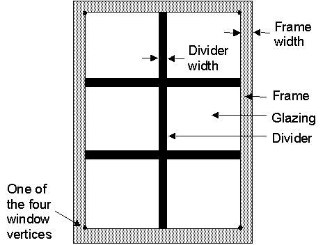
Figure 25. A window with a frame and divider.
In the illustration above, the divider has two horizontal elements and one vertical element.
The name of the frame/divider object. It is referenced by WindowProperty:FrameAndDivider Name in FenestrationSurface:Detailed.
Frame Fields
The width of the frame elements when projected onto the plane of the window. It is assumed that the top, bottom and side elements of the frame have the same width. If not, an average frame width should be entered such that the projected frame area calculated using the average value equals the sum of the areas of the frame elements.
The amount by which the frame projects outward from the outside surface of the window glazing. If the outer surface of the frame is flush with the glazing, Frame Outside Projection = 0.0. Used to calculate shadowing of frame onto glass, solar absorbed by frame, IR emitted and absorbed by frame, and convection from frame.
The amount by which the frame projects inward from the inside surface of the window glazing. If the inner surface of the frame is flush with the glazing, Frame Inside Projection = 0.0. Used to calculate solar absorbed by frame, IR emitted and absorbed by frame, and convection from frame.
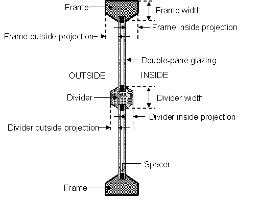
Figure 26. Illustration showing frame and divider dimensioning.
The effective thermal conductance of the frame measured from inside to outside frame surface (no air films) and taking 2-D conduction effects into account. Obtained from WINDOW 5 or other 2-D calculation.
The glass conductance near the frame (excluding air films) divided by the glass conductance at the center of the glazing (excluding air films). Used only for multi-pane glazing constructions. This ratio is greater than 1.0 because of thermal bridging from the glazing across the frame and across the spacer that separates the glass panes. Values can be obtained from WINDOW 5 for the user-selected glazing construction and frame characteristics.
The solar absorptance of the frame. The value is assumed to be the same on the inside and outside of the frame and to be independent of angle of incidence of solar radiation. If solar reflectance (or reflectivity) data is available, then absorptance is equal to 1.0 minus reflectance (for opaque materials).
The visible absorptance of the frame. The value is assumed to be the same on the inside and outside of the frame and to be independent of angle of incidence of solar radiation. If visible reflectance (or reflectivity) data is available, then absorptance is equal to 1.0 minus reflectance (for opaque materials).
The thermal emissivity of the frame, assumed the same on the inside and outside.
Divider Fields
The type of divider (see figure below). Divider Type = Suspended is applicable only to multi-pane glazing. It means that the divider is suspended between the panes. (If there are more than two glass layers, the divider is assumed to be placed between the two outermost layers.)
Divider Type = DividedLite means that the divider elements project out from the outside and inside surfaces of the glazing and divide the glazing into individual lites. For multi-pane glazing, this type of divider also has between-glass elements that separate the panes.
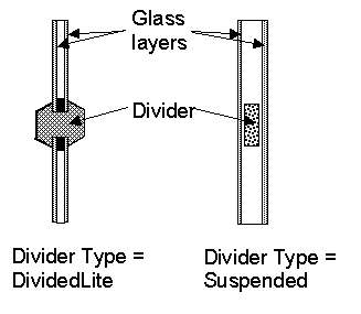
Figure 27. Illustration showing divider types.
The width of the divider elements when projected onto the plane of the window. It is assumed that the horizontal and vertical divider elements have the same width. If not, an average divider width should be entered such that the projected divider area calculated using the average value equals the sum of the areas of the divider elements.
The number of divider elements parallel to the top and bottom of the window.
The number of divider elements parallel to the sides of the window.
The amount by which the divider projects out from the outside surface of the window glazing. For Divider Type = Suspended, Divider Projection = 0.0. Used to calculate shadowing of divider onto glass, solar absorbed by divider, IR emitted and absorbed by divider, and convection from divider.
The amount by which the divider projects inward from the inside surface of the window glazing. If the inner surface of the divider is flush with the glazing, Divider Inside Projection = 0.0. Used to calculate solar absorbed by divider, IR emitted and absorbed by divider, and convection from divider.
The effective thermal conductance of the divider measured from inside to outside divider surface (no air films) and taking 2-D conduction effects into account. Obtained from WINDOW 5/6 or other 2-D calculation.
The glass conductance near the divider (excluding air films) divided by the glass conductance at the center of the glazing (excluding air films). Used only for multi-pane glazing constructions. This ratio is greater than 1.0 because of thermal bridging from the glazing across the divider and across the spacer that separates the glass panes. Values can be obtained from WINDOW 5/6 for the user-selected glazing construction and divider characteristics.
The solar absorptance of the divider. The value is assumed to be the same on the inside and outside of the divider and to be independent of angle of incidence of solar radiation. If solar reflectance (or reflectivity) data is available, then absorptance is equal to 1.0 minus reflectance (for opaque materials).
The visible absorptance of the divider. The value is assumed to be the same on the inside and outside of the divider and to be independent of angle of incidence of solar radiation. If visible reflectance (or reflectivity) data is available, then absorptance is equal to 1.0 minus reflectance (for opaque materials).
The thermal emissivity of the divider, assumed the same on the inside and outside.
Reveal Surface Fields
The following fields specify the properties of the window reveal surfaces (reveals occur when the window is not in the same plane as the base surface). From this information and from the geometry of the window and the sun position, the program calculates beam solar radiation absorbed and reflected by the top, bottom, right and left sides of outside and inside window reveal surfaces. In doing this calculation, the shadowing on a reveal surface by other reveal surfaces is determined using the orientation of the reveal surfaces and the sun position.
It is assumed that:
n The window is an exterior window.
n The reveal surfaces are perpendicular to the window plane.
n If an exterior shade, screen or blind is in place it shades exterior and interior reveal surfaces so that in this case there is no beam solar on these surfaces.
n If an interior shade or blind is in place it shades the interior reveal surfaces so that in this case there is no beam solar on these surfaces.
n The possible shadowing on inside reveal surfaces by a window divider is ignored.
n The outside reveal surfaces (top, bottom, left, right) have the same solar absorptance and depth. This depth is not input here but is automatically determined by the program—from window and wall vertices--as the distance between the plane of the outside face of the glazing and plane of the outside face of the parent wall.
n The inside reveal surfaces are divided into two categories: (1) the bottom reveal surface, called here the "inside sill;" and (2) the other reveal surfaces (left, right and top).
n The left, right and top inside reveal surfaces have the same depth and solar absorptance. The inside sill is allowed to have depth and solar absorptance values that are different from the corresponding values for the other inside reveal surfaces.
n The inside sill depth is required to be greater than or equal to the depth of the other inside reveal surfaces. If the inside sill depth is greater than zero the depth of the other inside reveal surfaces is required to be greater than zero.
n The reflection of beam solar radiation from all reveal surfaces is assumed to be isotropic diffuse; there is no specular component.
n Half of the beam solar reflected from outside reveal surfaces is goes towards the window; the other half goes back to the exterior environment (i.e., reflection of this outward-going component from other outside reveal surfaces is not considered).
n The half that goes towards the window is added to the other solar radiation incident on the window. Correspondingly, half of the beam solar reflected from inside reveal surfaces goes towards the window, with the other half going into the zone. The portion going towards the window that is not reflected is absorbed in the glazing or is transmitted back out into the exterior environment.
n The beam solar that is absorbed by outside reveal surfaces is added to the solar absorbed by the outside surface of the window's parent wall; similarly, the beam solar absorbed by the inside reveal surfaces is added to the solar absorbed by the inside surface of the parent wall.
The net effect of beam solar reflected from outside reveal surfaces is to increase the heat gain to the zone, whereas the effect of beam solar reflected from inside reveal surfaces is to decrease the heat gain to the zone since part of this reflected solar is transmitted back out the window.
If the window has a frame, the absorption of reflected beam solar by the inside and outside surfaces of the frame is considered. The shadowing of the frame onto interior reveal surfaces is also considered.
The solar absorptance of outside reveal surfaces.
The depth of the inside sill, measured from the inside surface of the glazing to the edge of the sill (see Figure 28).
The solar absorptance of the inside sill.
Field: Inside Reveal Depth
The depth of the inside reveal surfaces other than the sill, measured from the inside surface of the glazing to the edge of the reveal surface (see Figure 28).
The solar absorptance of the inside reveal surfaces other than the sill.
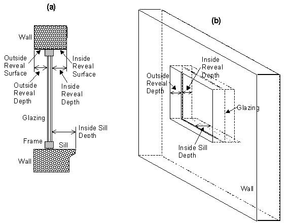
Figure 28. (a) Vertical section through a window (with frame) showing outside and inside reveal surfaces and inside sill. (b) Perspective view looking from the outside of a window (without frame) showing reveal surfaces. Note that “Outside Reveal Depth” is not a user input; it is calculated by the program from the window and wall vertices.
An IDF example:
WindowProperty:FrameAndDivider,
TestFrameAndDivider, ! Frame/Divider Name
0.05, ! Frame Width
0.04, ! Frame Outside Projection
0.03, ! Frame Inside Projection
5.0, ! Frame Conductance
1.3, ! Ratio of Frame-Edge Glass Conductance to Center-Of-Glass Conductance
0.8, ! Frame Solar Absorptance
0.8, ! Frame Visible Absorptance
0.9, ! Frame Thermal Emissivity
DividedLite, ! Divider Type
0.03, ! Divider Width
2, ! Number of Horizontal Dividers
2, ! Number of Vertical Dividers
0.03, ! Divider Outside Projection
0.03, ! Divider Inside Projection
5.0, ! Divider Conductance
1.3, ! Ratio of Divider-Edge Glass Conductance to Center-Of-Glass Conductance
0.8, ! Divider Solar Absorptance
0.8, ! Divider Visible Absorptance
0.9, ! Divider Thermal Emissivity
0.7, ! Outside Reveal Solar Absorptance
0.25, ! Inside Sill Depth (m)
0.6, ! Inside Sill Solar Absorptance
0.2, ! Inside Reveal Depth (m)
0.5; ! Inside Reveal Solar Absorptance
This object is used to specify the control mechanism for windows in which forced air flows in the gap between adjacent layers of glass. Such windows are called “airflow windows.” They are also known as “heat-extract windows” or “climate windows.”
A common application is to reduce the zone load by exhausting indoor air through the window. In the cooling season this picks up and expels some of the solar heat absorbed by the window glass (and by the between-glass shade or blind, if present). In the heating season this warms the window, reducing the heat loss from the window. A side benefit is increased thermal comfort. This is because the inside surface of the window will generally be cooler in summer and warmer in winter.
The surface report variable “Window Gap Convective Heat Flow [W]” gives the heat picked up (or lost) by the gap airflow.
Name of the window that this WindowProperty:AirflowControl refers to. It must be a window with two or three glass layers, i.e., double- or triple-glazing. For triple-glazing the airflow is assumed to be between the two inner glass layers.
An error will result if the gas in the airflow gap is other than air. If an airflow window has a between-glass shade or blind, the gas in the gap on either side of the shade or blind must be air.
The source of the gap airflow. The choices are:
IndoorAir: Indoor air from the window’s zone is passed through the window.
OutdoorAir: Outdoor air is passed through the window.
This is where the gap air goes after passing through the window. The choices are:
IndoorAir: The gap air goes to the indoor air of the window’s zone.
OutdoorAir: The gap air goes to the outside air.
ReturnAir. The gap air goes to the return air for the window’s zone. This choice is allowed only if Airflow Source = InsideAir. If the return air flow is zero, the gap air goes to the indoor air of the window’s zone. If the sum of the gap airflow for all of the windows in a zone with Airflow Destination = ReturnAir exceeds the return airflow, then the difference between this sum and the return airflow goes to the indoor air.
Figure 29 shows the allowed combinations of Airflow Source and Airflow Destination. The allowed combinations of Airflow Source and Airflow Destination are:
IndoorAir à OutdoorAir
IndoorAir à IndoorAir
IndoorAir à ReturnAir
OutdoorAir à IndoorAir
OutdoorAir à OutdoorAir
The maximum value of the airflow, in m3/s per m of glazing width. The value is typically 0.006 to 0.009 m3/s-m (4 to 6 cfm/ft).
The airflow can be modulated by specifying Airflow Has Multiplier Schedule = Yes and giving the name of the Airflow Multiplier Schedule (see below).
The fan energy used to move the air through the gap is generally very small and so is ignored.
Specifies how the airflow is controlled. The choices are:
AlwaysOnAtMaximumFlow. The airflow is always equal to Maximum Airflow.
AlwaysOff. The airflow is always zero.
ScheduledOnly. The airflow in a particular timestep equals Maximum Airflow times the value of the Airflow Multiplier Schedule for that timestep.
Specifies if the airflow is scheduled. The choices are:
Yes. The airflow is scheduled.
No. The airflow is not scheduled.
If Yes, Airflow Multiplier Schedule Name is required.
The name of a schedule with values between 0.0 and 1.0. The timestep value of the airflow is Maximum Airflow times the schedule value. Required if Airflow Is Scheduled = Yes. Unused if Airflow Is Scheduled = No. This schedule should have a ScheduleType with Numeric Type = Continuous and Range = 0.0 : 1.0.
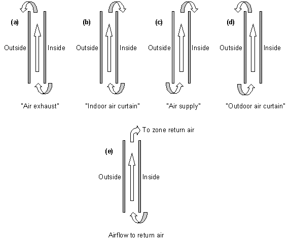
Figure 29. Gap airflow configurations for airflow windows. (a) Air exhaust window: Airflow Source = InsideAir, Airflow Destination = OutsideAir; (b) Indoor air curtain window: Airflow Source = InsideAir, Airflow Destination = InsideAir; (c) Air supply window: Airflow Source = OutsideAir, Airflow Destination = InsideAir; (d) Outdoor air curtain window: Airflow Source = OutsideAir, Airflow Destination = OutsideAir; (e) Airflow to Return Air: Airflow Source = InsideAir, Airflow Destination = ReturnAir. Based on “Active facades,” Version no. 1, Belgian Building Research Institute, June 2002.
An IDF example: window with a constant airflow from inside to outside at 0.008 m3/s-m.
WindowProperty:AirflowControl, !- Used to control forced airflow through a gap between glass layers
Zn001:Wall001:Win002, !- Name of Associated Window
InsideAir, !- Airflow Source
OutsideAir, !- Airflow Destination
0.008, !- Maximum Airflow (m3/s per m of glazing width)
AlwaysOnAtMaxFlow, !- Airflow Control Type
No, !- Airflow Has Multiplier Schedule?
; !- Name of Airflow Multiplier Schedule
This object allows you to assign a movable exterior glass layer (“storm window” or “storm glass”) that is usually applied to a window in the winter to reduce heat loss and removed in the summer. A WindowProperty:StormWindow object is required for each window that has an associated storm window. It is assumed that:
n When the storm glass is in place it is the outermost layer of the window, it covers only the glazed part of the window and not the frame, and it forms a tight seal. See Figure 30.
n When the storm glass is not in place it is completely removed and has no effect on window heat transfer.
n The gap between the storm glass and rest of the glazing is filled with air.
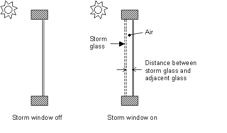
Figure 30. Section through a single-glazed window without (left) and with (right) a storm glass layer. Not to scale.
With the addition of a storm window, single glazing effectively becomes double glazing, double glazing becomes triple glazing, etc.
The presence of a storm window is indicated by the report variable “Storm Window On/Off Flag” (see “Window Output Variables”). This flag is 0 if the storm window is off, 1 if it is on, and –1 if the window does not have an associated storm window.
The program automatically creates a window construction (ref: Construction) that consists of the storm window glass layer and its adjacent air layer added to the original (unshaded, or “bare”) window construction. In the eplusout.eio file this construction is called BARECONSTRUCTIONWITHSTORMWIN:n, where n is the number of the associated StormWin object. If the window has a shaded construction, the program creates a construction called SHADEDCONSTRUCTIONWITHSTORMWIN:n that consists of the storm window glass layer and its adjacent air layer added to the original shaded window construction.
The program also creates a WindowMaterial:Gas layer corresponding to the air layer adjacent to the storm glass. In the eplusout.eio file this layer is called AIR:STORMWIN:kMM, where k is the thickness of the air layer expressed as an integer number of millimeters.
This is the name of a window (or glass door) to which the storm glass is applied. Not all windows can accept WindowProperty:StormWindow. The rules are:
n The window must be an exterior window. WindowProperty:StormWindow is not applicable to interior (interzone) windows.
n The window construction (without the storm glass layer) can have up to three glass layers.
n If the window has an associated shaded construction (ref: WindowProperty:ShadingControl), that construction can have an interior shade or blind and up to three glass layers, or a between-glass shade or blind and two glass layers. The shaded construction cannot have an exterior shade or blind, cannot have a between-glass shade or blind and three glass layers, and cannot be switchable glazing.
n The window cannot be an airflow window, i.e., a window that has an associated WindowProperty:AirflowControl.
This is the name of a window glass material. Storm windows are assumed to consist of a single layer of glass. A storm window frame, if present, is ignored.
The separation between the storm glass and the rest of the window (Figure 30). It is measured from the inside of the storm glass layer to the outside of the adjacent glass layer.
The number of the month (January = 1, February = 2, etc.) during which the storm window is put in place.
The day of the month that the storm window is put in place. It is assumed that the storm window is put in place at the beginning of this day, i.e., during the first simulation timestep of the day, and remains in place until that month and day given by the following two fields.
The number of the month (January = 1, February = 2, etc.) during which the storm window is removed.
The day of the month that the storm window is removed. It is assumed that the storm window is removed at the beginning of this day, i.e., during the first simulation timestep of the day, and stays off until the month and day given by Month that Storm Glass Layer Is Put On, Day of Month that Storm Glass Layer Is Put On.
In the northern hemisphere, the month the storm window is put on is generally greater than the month it is taken off (for example put on in month 10, when it starts to get cold, and taken off in month 5, when it starts to warm up). In the southern hemisphere this is reversed: month on is less than month off.
An IDF example of WindowProperty:StormWindow. The storm window is put in place on October 15 and removed on May 1.
WindowProperty:StormWindow,
Window1, !- Name of Window to Which Storm Window Glass Layer is Applied
GlassA, !- Name of Material:WindowGlass or MATERIAL:WindowGlass:AltInput that is the storm window layer
0.060, !- Distance from storm window to adjacent glass (m)
10, !- Month that Storm Window Is Put On
15, !- Day of Month that Storm Window Is Put On
5, !- Month that Storm Window Is Taken Off
1; !- Day of Month that Storm Window Is Taken Off
WINDOW 6.3 is capable of writing IDF excerpts for Window data. This is the preferred method as no external file is necessary.
The WINDOW 5 program calculates the U-value, Solar Heat Gain Coefficient, solar transmission/absorption characteristics, visible transmission characteristics and other properties of a window under standard indoor and outdoor conditions. WINDOW 5 treats the whole window system—glazing, frame and divider. A sub-program of WINDOW 5 called THERM uses a 2-D finite element calculation to determine the effective conductance of frame, divider and edge-of-glass elements. Another sub-program, OPTICS 5, determines the solar-optical properties of glazing, including laminates and coated glass.
WINDOW 5 writes a data file containing a description of the window that was analyzed. An example is shown below. This file, which can be named by the user, can be read by EnergyPlus. For more complete description and examples, see the object description -- Construction:WindowDataFile.
In this way, the same window that was created in WINDOW 5 can be imported into EnergyPlus for annual energy analysis without having to re-input the window data. To obtain WINDOW 5 go to http://windows.lbl.gov. A major advantage of using WINDOW 5 to create window input for EnergyPlus is that you will have direct access to WINDOW 5’s expanding database of over 1000 different glass types; and you will be able to browse through this database according to different criteria (color, transmittance, solar heat gain coefficient, etc.) to help you select the best glass type for your application.
Although WINDOW 5 writes only one window entry on the WINDOW 5 data file, EnergyPlus users can combine two or more of these files to end up with a single WINDOW 5 data file with multiple window entries of different types. In this way a library of windows from WINDOW 5 can be built up if so desired. If you combine files like this you should be sure not to leave out or change any of lines from the original files.
n There are three methods for inputting window constructions in EnergyPlus:
1) input full spectral data for each layer in the IDF,
2) input spectral average data for each layer in the IDF,
3) import WINDOW 5 report containing layer-by-layer calculated values and overall glazing system angular values.
Note: When using method 3, the overall glazing system angular dependent properties, including Tsol, Abs, Rfsol, Rbsol, Tvis, Rfvis, and Rbvis, are not used by EnergyPlus. Therefore, methods 1 and 2 are recommended.
n The SHGC calculations in EnergyPlus for window layers input using full spectral data use a spectral weighting data set (derived from Optics5 data file ISO-9845GlobalNorm.std) that is different from the WINDOW 5 default spectral weighting data set (W5_NFRC_2003.std). This difference accounts for most of the variation in SHGC values reported by EnergyPlus and WINDOW 5 for full spectral data window layer input. This variation is more pronounced for window constructions of three glass layers or more.
n Users intending to select a window construction based on SHGC value for energy code compliance should base their selection on the value reported by WINDOW 5 since this is the officially recognized value.
Please note that there is a bug in WINDOW 5 that causes two of the lines in the EnergyPlus data file to be joined. This bug is fixed in versions of Window 5.02 (and above). To be sure, you can check the data file for a line that looks like:
GLAZING SYSTEM OPTICAL DATAAngle 0 10 20 30 40 50 60 70 80 90 Hemis
The fixed version of the program will not show the above line; rather, there will be two lines such as shown below. If you have the above condition, with an editor you would break this into two lines:
GLAZING SYSTEM OPTICAL DATA
Angle 0 10 20 30 40 50 60 70 80 90 Hemis
In EnergyPlus, the Window5 data file is searched for each “Construction from Window5 Data File” object in the EnergyPlus input. This object has a very simple form:
Construction:WindowDataFile,
ConstructionName,
FileName; ! Default is Window5DataFile.dat in the “run” folder.
If there is a window called ConstructionName on the Window5 data file, the data for that window is read from the file and the following EnergyPlus objects and their names are created. The “W5” prefixed to these names indicates that the object originated in the Window5 data file.
n WindowMaterial:Glazing for each of the glass layers. They will be named W5:ConstructionName:GLASS1,W5:ConstructionName:GLASS2 , etc.
n WindowMaterial:Gas or WindowMaterial:GasMixture for each of the gap layers. They will be named W5:ConstructionName:GAP1, W5:ConstructionName:GAP2 , etc.
n WindowProperty:FrameAndDivider (if the window on the Window5 data file has a frame and/or divider). It will be named W5:ConstructionName. This WindowProperty:FrameAndDivider will be assigned to any window on the input file that has a construction called “ConstructionName” even if that window has referenced another WindowProperty:FrameAndDivider (i.e., if WindowProperty:FrameAndDivider Name for that window is specified). In this case a warning will result.
Note that:
An entry on the WINDOW 5 data file usually has just one glazing system. It is also possible to have an entry with two glazing systems separated by a horizontal or vertical mullion. In this case, the two glazing systems can have different dimensions and different properties. For example, one of the two glazing systems could be single glazed and the other could be double glazed. An example of the two glazing system case is given in the sample WINDOW 5 data file shown below (although in this case the properties of the two glazing systems are the same).
EnergyPlus handles the “one glazing system” and “two glazing systems” cases differently. If there is one glazing system, the glazing system height and width from the Window5 data file are not used. Instead, the window dimensions are obtained from the window vertices that have been specified on the IDF file. However, a warning message will result if the height or width calculated from the window’s vertex inputs differs from the corresponding Window5 data file values by more than 10%. This warning is given since the effective frame and edge-of-glass conductances on the WINDOW 5 data file can depend on the window dimensions if the frame is non-uniform, i.e., consists of sections with different values of width, projection, or thermal properties.
If the WINDOW 5 data file entry has two glazing systems, System1 and System2, the following happens, as shown in the figure below. Assume that the original window is called WinOriginal. System1 is assigned to WinOriginal. Then EnergyPlus automatically creates a second window, called WinOriginal:2, and assigns System2 to it. The dimensions of WinOriginal are ignored; the dimensions of System1 on the data file are assigned to it, but the position of the lower left-hand vertex of WinOriginal is retained. The dimensions of System2 on the data file are assigned to WinOriginal:2. The lower left-hand vertex of WinOriginal:2 is determined from the mullion orientation and width.
Note: WinOriginal would have been the IDF window definition – it’s dimensions will be overridden by the systems dimensions from the Window 5 data file. Two windows will be made and called WinOriginal and WinOriginal:2.
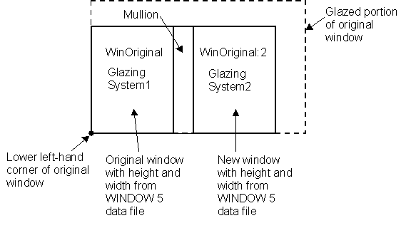
Figure 31. Window5 Glazing system with dual glazing constructions
The Window5 Data File contains no information on shading devices. See “Specify the Material Name of the Shading Device” under WindowProperty:ShadingControl for a method to attach a shading layer to windows read in from this file.
Following is an example WINDOW 5 data file for a slider window with two identical double low-E glazing systems separated by a horizontal mullion. Each system has a frame and divider. Note that all dimensions, such as glazing height and width, are in millimeters; when EnergyPlus reads the file these are converted to meters. Following the data file example is a description of the contents of the file. That data used by EnergyPlus is shown in bold.
Window5 Data File for EnergyPlus
Window 5.0 v5.0.73
Date : Tue Nov 13 17:07:40 2001
Window name : DoubleLowE
Description : Horizontal Slider, AA
# Glazing Systems: 2
GLAZING SYSTEM DATA: Height Width nPanes Uval-center SC-center SHGC-center Tvis-center
System1 : 1032 669 2 1.660 0.538 0.467 0.696
System2 : 1033 669 2 1.660 0.538 0.467 0.696
FRAME/MULLION DATA: Width OutsideProj InsideProj Cond EdgeCondRatio SolAbs VisAbs Emiss Orient'n (mull)
L Sill : 97.3 25.4 25.4 500.000 1.467 0.500 0.500 0.90
R Sill : 97.3 25.4 25.4 500.000 1.467 0.500 0.500 0.90
L Head : 70.2 25.4 25.4 18.822 1.490 0.500 0.500 0.90
R Head : 70.2 25.4 25.4 18.822 1.490 0.500 0.500 0.90
Top L Jamb : 54.3 25.4 25.4 31.141 1.503 0.500 0.500 0.90
Bot L Jamb : 54.3 25.4 25.4 500.000 1.494 0.500 0.500 0.90
Top R Jamb : 70.2 25.4 25.4 500.000 1.518 0.500 0.500 0.90
Bot R Jamb : 97.6 25.4 25.4 264.673 1.547 0.500 0.500 0.90
Mullion : 53.5 25.4 25.4 500.000 1.361 0.500 0.500 0.90 Horizontal
Average frame: 75.5 25.4 25.4 326.149 1.464 0.500 0.500 0.90
DIVIDER DATA : Width OutsideProj InsideProj Cond EdgeCondRatio SolAbs VisAbs Emiss Type #Hor #Vert
System1 : 25.4 25.4 25.4 3.068 1.191 0.500 0.500 0.900 DividedLite 2 3
System2 : 25.4 25.4 25.4 3.068 1.191 0.500 0.500 0.900 DividedLite 2 3
GLASS DATA : Layer# Thickness Cond Tsol Rfsol Rbsol Tvis Rfvis Rbvis Tir EmissF EmissB SpectralDataFile
System1 : 1 3.00 0.900 0.50 0.33 0.39 0.78 0.16 0.13 0.00 0.16 0.13 CMFTIR_3.AFG
2 6.00 0.900 0.77 0.07 0.07 0.88 0.08 0.08 0.00 0.84 0.84 CLEAR_6.DAT
System2 : 1 3.00 0.900 0.50 0.33 0.39 0.78 0.16 0.13 0.00 0.16 0.13 CMFTIR_3.AFG
2 6.00 0.900 0.77 0.07 0.07 0.88 0.08 0.08 0.00 0.84 0.84 CLEAR_6.DAT
GAP DATA : Gap# Thick nGasses
System1 : 1 12.70 1
System2 : 1 12.70 1
GAS DATA : GasName Fraction MolWeight ACond BCond CCond AVisc BVisc CVisc ASpHeat BSpHeat CSpHeat
System1 Gap1 : Air 1.0000 28.97 0.002873 7.76e-5 0.0 3.723e-6 4.94e-8 0.0 1002.737 0.012324 0.0
System2 Gap1 : Air 1.0000 28.97 0.002873 7.76e-5 0.0 3.723e-6 4.94e-8 0.0 1002.737 0.012324 0.0
GLAZING SYSTEM OPTICAL DATA
Angle 0 10 20 30 40 50 60 70 80 90 Hemis
System1
Tsol 0.408 0.410 0.404 0.395 0.383 0.362 0.316 0.230 0.106 0.000 0.338
Abs1 0.177 0.180 0.188 0.193 0.195 0.201 0.218 0.239 0.210 0.001 0.201
Abs2 0.060 0.060 0.061 0.061 0.063 0.063 0.061 0.053 0.038 0.000 0.059
Rfsol 0.355 0.350 0.348 0.350 0.359 0.374 0.405 0.478 0.646 0.999 0.392
Rbsol 0.289 0.285 0.283 0.282 0.285 0.296 0.328 0.411 0.594 1.000 0.322
Tvis 0.696 0.700 0.690 0.677 0.660 0.625 0.548 0.399 0.187 0.000 0.581
Rfvis 0.207 0.201 0.198 0.201 0.212 0.234 0.278 0.374 0.582 0.999 0.260
Rbvis 0.180 0.174 0.173 0.176 0.189 0.215 0.271 0.401 0.648 1.000 0.251
System2
Tsol 0.408 0.410 0.404 0.395 0.383 0.362 0.316 0.230 0.106 0.000 0.338
Abs1 0.177 0.180 0.188 0.193 0.195 0.201 0.218 0.239 0.210 0.001 0.201
Abs2 0.060 0.060 0.061 0.061 0.063 0.063 0.061 0.053 0.038 0.000 0.059
Rfsol 0.355 0.350 0.348 0.350 0.359 0.374 0.405 0.478 0.646 0.999 0.392
Rbsol 0.289 0.285 0.283 0.282 0.285 0.296 0.328 0.411 0.594 1.000 0.322
Tvis 0.696 0.700 0.690 0.677 0.660 0.625 0.548 0.399 0.187 0.000 0.581
Rfvis 0.207 0.201 0.198 0.201 0.212 0.234 0.278 0.374 0.582 0.999 0.260
Rbvis 0.180 0.174 0.173 0.176 0.189 0.215 0.271 0.401 0.648 1.000 0.251
Description of Contents of Window5 Data File
(Quantities used in EnergyPlus are in bold; others are informative only)
Second line = version of WINDOW5 used to create the data file
Date = date the data file was created
Window name = name of this window; chosen by WINDOW5 user; EnergyPlus user enters the same name in EnergyPlus as name of a “Construction from Window5 Data File” object. EnergyPlus will search the Window5 data file for an entry of this name.
Description = One-line description of the window; this is treated as a comment.
# Glazing Systems: 1 or 2; value is usually 1 but can be 2 if window has a horizontal or vertical mullion that separates the window into two glazing systems that may or may not be different.
GLAZING SYSTEM DATA
System1, System2: separate characteristics given if window has a mullion.
Height, *width = height and width of glazed portion (i.e., excluding frame; and, if mullion present, excluding mullion).
nPanes = number of glass layers
Uval-center = center-of-glass U-value (including air films) under standard winter conditions* (W/m2)
SC-center = center-of-glass shading coefficient under standard summer conditions*.
SHCG-center = center-of-glass solar heat gain coefficient under standard summer conditions*.
Tvis-center = center-of-glass visible transmittance at normal incidence
FRAME/MULLION DATA
L,R Sill = left, right sill of frame
L,R Head = left, right header of frame
Top L, Bot L jamb = top-left, bottom-left jamb of frame
Bot L, Bot R jamb = bottom-left, bottom-right jamb of frame
Average frame = average characteristics of frame for use in EnergyPlus calculation. If mullion is present, original window is divided into two separate windows with the same average frame (with the mullion being split lengthwise and included in the average frame).
Width = width (m)
OutsideProj = amount of projection from outside glass (m)
InsideProj = amount of projection from inside glass (m)
Cond = effective surface-to-surface conductance (from THERM calculation) (W/m2)
EdgeCondRatio = ratio of surface-to-surface edge-of-glass conductance to surface-to-surface center-of-glass conductance (from THERM calculation)
SolAbs = solar absorptance
VisAbs = visible absorptance
Emiss = hemispherical thermal emissivity
Orientation = Horizontal or Vertical (mullion only); = None if no mullion.
DIVIDER DATA
Width through Emiss are the same as for FRAME/MULLION DATA
#Hor = number of horizontal dividers
#Vert = number of vertical dividers
Type = DividedLite or Suspended
GLASS DATA
System1, System2: separate characteristics are given if window has a mullion.
Cond = conductivity (W/m-K)
Tsol = spectral-average solar transmittance at normal incidence
Rfsol = spectral-average front solar reflectance at normal incidence
Rbsol = spectral-average back solar reflectance at normal incidence
Tvis = spectral-average visible transmittance at normal incidence
Rfvis = spectral-average front visible reflectance at normal incidence
Rbvis = spectral-average back visible reflectance at normal incidence
Tir = hemispherical IR transmittance
EmissF = hemispherical front emissivity
EmissB = hemispherical back emissivity
SpectralDataFile = name of spectral data file with wavelength-dependent transmission and reflection data used by WINDOW 5 to calculate the glazing system optical data. “None” will appear here if spectral-average data for this glass layer were used by WINDOW 5.
GAP DATA
System1, System2: separate characteristics are given if the window has a mullion.
Thick = thickness (m)
nGasses = number of gasses (1, 2 or 3)
GasName = name of the gas
Fraction = fraction of the gas
MolecWeight = molecular weight of the Nth gas
(In the following, conductivity, viscosity and specific heat as a function
of temperature, T (deg K), are expressed as A + B*T + C*T^2)
ACond = A coeff of conductivity (W/m-K)
BCond = B coeff of conductivity (W/m-K^2)
CCond = C coeff of conductivity (W/m-K^3)
AVisc = A coeff of viscosity (g/m-s)
BVisc = B coeff of viscosity (g/m-s-K)
CVisc = C coeff of viscosity (g/m-s-K^2)
ASpHeat = A coeff of specific heat (J/kg-K)
BSpHeat = B coeff of specific heat (J/kg-K^2)
CSpHeat = C coeff of specific heat (J/kg-K^3)
GLAZING SYSTEM OPTICAL DATA
System1, System2: separate characteristics are given if the window has a mullion.
Hemisph = hemispherical (i.e., diffuse)
Tsol = solar transmittance vs. angle of incidence
AbsN = solar absorptance of Nth layer vs. angle of incidence
Rfsol = front solar reflectance vs. angle of incidence
Rbsol = back solar reflectance vs. angle of incidence
Tvis = visible transmittance vs. angle of incidence
Rfvis = front visible reflectance vs. angle of incidence
Rbvis = back visible reflectance vs. angle of incidence
---------------------------------------------------------
*Standard conditions are
Winter:
Indoor air temperature = 21.1C (70F)
Outdoor air temperature = -17.8C (0F)
Wind speed = 6.71 m/s (15 mph)
No solar radiation
Summer:
Indoor air temperature = 23.9C (75F)
Outdoor air temperature = 31.7C (89F)
Wind speed = 3.35 m/s (7.5 mph)
783 W/m2 (248 Btu/h-ft2) incident beam solar radiation normal to glazing
In addition to the canned Surface reports (view the Reports section later in this document) and surface variables (above), the following variables are available for all zones:
Zone,Sum,Zone Total Internal Radiant Heat Gain [J]
Zone,Sum,Zone Total Internal Visible Heat Gain [J]
Zone,Sum,Zone Total Internal Convective Heat Gain [J]
Zone,Sum,Zone Total Internal Latent Gain [J]
Zone,Sum,Zone Total Internal Total Heat Gain [J]
Zone,Average,Zone Mean Air Temperature [C]
HVAC,Average,Zone/Sys Air Temperature[C]
Zone,Average,Zone Mean Radiant Temperature [C]
Zone,Average,Zone Operative Temperature [C]
HVAC,Sum,Zone/Sys Sensible Heating Energy[J]
HVAC,Sum,Zone/Sys Sensible Cooling Energy[J]
HVAC,Average,Zone/Sys Sensible Heating Rate[W]
HVAC,Average,Zone/Sys Sensible Cooling Rate[W]
HVAC,Average,Zone Air Humidity Ratio[]
HVAC,Average,Zone Air Relative Humidity[%]
Two of these are of particular interest:
Zone,Average,Zone Mean Air Temperature [C]
HVAC,Average,Zone/Sys Air Temperature [C]
These two variable outputs are/should be identical. However, note that they can be reported at different time intervals. “Zone Mean Air Temperature” is only available on the Zone/HB timestep (Number of Timesteps per Hour) whereas “Zone/Sys Air Temperature” can be reported at the HVAC timestep (which can vary).
From the code definition, the zone mean air temperature is the average temperature of the air temperatures at the system timestep. Remember that the zone heat balance represents a “well stirred” model for a zone, therefore there is only one mean air temperature to represent the air temperature for the zone.
This is very similar to the mean air temperature in the last field. The “well stirred” model for the zone is the basis, but this temperature is also available at the “detailed” system timestep.
The Mean Radiant Temperature (MRT) in degrees Celsius of a space is really the measure of the combined effects of temperatures of surfaces within that space. The larger the surface area and the closer one is to it, the more effect the surface temperature of that surface has on each other. The MRT is the measure of all these surface areas and temperatures.
Zone Operative Temperature (OT) is the average of the Zone Mean Air Temperature (MAT) and Zone Mean Radiant Temperature (MRT), OT = 0.5*MAT + 0.5*MRT. This report variable is not affected by the type of thermostat controls in the zone, and does not include the direct effect of high temperature radiant systems. See also Zone Thermostat Operative Temperature.
This field represents the sensible heating energy in Joules that is actually supplied by the system to that zone for the timestep reported. This is the sensible heating rate multiplied by the simulation timestep. This is calculated and reported from the Correct step in the Zone Predictor-Corrector module. . This field is not multiplied by zone or group multipliers.
Zone/Sys Sensible Heating (and Cooling) Energy (and Rate) all report the heating or cooling delivered by the HVAC system to a zone. These values are calculated by multiplying the supply air mass flow rate by the difference between the supply air temperature and the zone air temperature. This does not always indicate the operation of heating or cooling coils. For example, cooling will be reported if the supply air is cooled due to the introduction of outside air, even if all coils are off.
Note that these variables are calculated at the system timestep. When reported at the "detailed" reporting frequency, these variable will never show heating and cooling both in the same system timestep. If reported at a frequency less than "Detailed" (for example, Hourly) values may appear in both the heating and cooling variable for the same hour if the system cooled the zone for part of the reporting period and heated the zone for another part of the reporting period.
This field represents the sensible cooling energy in Joules that is actually supplied by the system to that zone for the timestep reported. This is the sensible cooling rate multiplied by the simulation timestep. This is calculated and reported from the Correct step in the Zone Predictor-Corrector module. This field is not multiplied by zone or group multipliers.
This field represents the sensible heating rate in Watts that is actually supplied by the system to that zone for the timestep reported. This is calculated and reported from the Correct step in the Zone Predictor-Corrector module. This field is not multiplied by zone or group multipliers.
This field represents the sensible cooling rate in Watts that is actually supplied by the system to that zone for the timestep reported. This is calculated and reported from the Correct step in the Zone Predictor-Corrector module. This field is not multiplied by zone or group multipliers.
This field represents the air humidity ratio after the correct step for each zone. The humidity ratio is the mass of water vapor to the mass of dry air contained in the zone in (kg water/kg air) and is unitless.
This field represents the air relative humidity ratio after the correct step for each zone. The relative humidity is in percent and uses the Zone Air Temperature, the Zone Air Humidity Ratio and the Outside Barometric Pressure for calculation.
This field represents the sum of radiant gains from specific internal sources (e.g. equipment) throughout the zone in joules. This includes radiant gain from People, Lights, Electric Equipment, Gas Equipment, Other Equipment, Hot Water Equipment, and Steam Equipment.
This field expresses the sum of heat gain in joules that is the calculated short wavelength radiation gain from lights in the zones. This calculation uses the total energy from lights and the fraction visible to realize this value, summed over the zones in the simulation.
This field represents the sum of convective gains from specific sources (e.g. equipment) throughout the zone in joules. This includes convective gain from People, Lights, Electric Equipment, Gas Equipment, Other Equipment, Hot Water Equipment, and Steam Equipment.
This field represents the sum of latent gains from specific internal sources (e.g. equipment) throughout the zone in joules. This includes latent gain from People, Electric Equipment, Gas Equipment, Other Equipment, Hot Water Equipment, and Steam Equipment.
This field represents the sum of all heat gains throughout the zone in joules. This includes all heat gains from People, Lights, Electric Equipment, Gas Equipment, Other Equipment, Hot Water Equipment, and Steam Equipment.
This group of objects describe concepts applied to heat transfer surfaces that are of an advanced nature. Careful consideration must be given before using these.
Movable insulation can be used/scheduled on any surface regular surface (such as a wall, floor, roof, etc.) but not on a subsurface (such as a window, use WindowProperty:ShadingControl instead). With movable insulation, no reference is made in the surface that is using the insulation – rather the movable insulation statement references the surface to which it is applied.
Exterior movable insulation has undergone some testing and appears to producing expected results. Interior movable insulation has not yet been tested. The underlying principle has been implemented in EnergyPlus for both interior and exterior movable insulation with the possibility for exterior movable insulation to be transparent (transparent insulation material or TIM).
TIM exterior layers can be used with the ConductionFiniteDifference (CondFD) solution algorithm. With this addition, TIM layers can be used in conjunction with wall layers that have phase change materials (PCM) included, or any other advanced capability of the CondFD algorithm such as variable conductivity. The input requirements are exactly the same as when used with the CTF algorithm. The Solution Algorithm needs to be changed to CondFD, and as with CTF, the “SurfaceControl:MovableInsulation” object must be completed to specify the insulated surface and the “WindowMaterial:Glazing” object is needed to provide the TIM layer properties.
Basically, the addition of movable insulation allows the user to schedule an extra amount of insulation on either the inside or outside surface of a wall (or both). The insulation must be a simple, homogenous material layer (linked to a material definition within the input data file). Note that EnergyPlus allows the exterior movable insulation layer to be transparent to short wavelength radiation (solar). In this case, incident solar is split between the plane between the movable insulation and the surface and the plane between the movable insulation and the surrounding air. This calculation is fairly basic and based on the solar transmittance of the insulation layer (material properties). Using transparent layers for exterior movable insulation allows solar energy to penetrate deeper into a construction where it can be stored for later use in the building (similar in concept to a Trombe Wall).
This field determines whether the movable insulation is applied to the inside or the outside of the surface by entering either “Inside” or “Outside”, respectively.
This field refers the movable insulation back to a particular surface (ref: Building Surfaces) via its user assigned name so that EnergyPlus knows where to apply this extra layer of insulation. This will affect either the inside or outside surface heat balance of this surface depending on the value in the insulation type field (see previous field).
This field refers to a material layer (e.g., Material, Material:NoMass, or WindowMaterial:Glazing; transparent layers are only valid for outside movable insulation) via its user assigned name. This provides the program with a full complement of material properties so that the effect of the insulation (R-value and solar transmittance) can be correctly taken into account by EnergyPlus.
This field is a schedule that theoretically can be any positive real number but was originally intended to be a parameter between 0.0 and 1.0. Its purpose is to act as a fractional modifier on the resistance of the material layer. The actual thermal resistance of the movable insulation is equal to the resistance of the material layer times the current value in the movable insulation schedule. A value of 0.0 simply means that the movable insulation is not present.
An example of this syntax implemented in an input file is:
SurfaceControl:MoveableInsulation,
Exterior, ! Insulation Type
Zone001:Wall001, ! Surface Name
TransparentInsulationMaterial, ! Material Name
PresentInWinterSchedule; ! Schedule Name
By referencing the Other Side Coefficients statement in the surface statements (i.e. Outside Boundary Condition), the temperature of the outer plane of a surface (see Figure 32) can be directly controlled. Other side coefficients can also be used to control the exterior convective heat transfer coefficient of a surface and the corresponding exterior air temperature. It should be noted that solar effects are not accounted for when other side coefficients are used. In addition, if other side coefficients are specified for a surface, they also hold for subsurfaces of that surface (though subsurfaces can have their own coefficient set).
other side coefficients have the same effect on all types of heat transfer surfaces. In other words, an interior surface with other side coefficients specified and an exterior wall with identical other side coefficients specified are simulated exactly the same. A surface that uses other side coefficients should be thought of as a new or separate type of surface. All heat transfer surfaces are simulated in the same manner through conduction transfer functions. The only difference between the various types of heat transfer surfaces is the environment on the other side of the surface. For example, the other side environment of an exterior surface is the outdoor environment. For an interior surface, the temperature of the outer plane of the surface is set equal to the temperature of the inner plane of the surface. Similarly, a surface with other side coefficients specified will allow the user to control the other side environment.
Heat transfer through a surface is an extremely important component in the calculation of zone loads. The information to calculate this heat transfer is readily available if the surface is exposed to the outdoor environment or to another zone that is being simulated. Occasionally, a user will want to model the heat transfer through a surface that is adjacent to an area that is not included in the EnergyPlus model. For example, an office area is attached to a warehouse and the user is only interested in simulating the office area. An interior surface with other side coefficients specified could be used to control the environment on the other side of the surface, thereby accounting for the heat transfer through the adjoining surface.
Other Side Coefficients affects the "other side" of a surface as described below. Each coefficient has a special meaning. You may enter a 0 or blank if you are not using a particular coefficient. Note that there are two potential ways to use other side coefficients. Either they are used to set the temperature of the exterior side surface directly (if the combined convective/radiative coefficient below is less than or equal to zero) or to set both the film coefficient (positive value for the combined convective/radiative coefficient below) and the outside air temperature.
This, of course, is the string referenced in the Surface statement that is using OtherSideCoefficients as the Outside Boundary Condition.
This is a trigger value. If the value is greater than zero, then it is taken to be the combined convective/radiative film coefficient. In this case (value > 0), the remaining fields are used first to calculate the outside air temperature for the surface and then to calculate the outside surface temperature based on the outside air temperature and the film coefficient. If this field is less than or equal to zero, then the remaining fields are used to calculate the surface temperature (not the outside air temperature). The units for this field are the same as for a convective heat transfer coefficient: W/(m2*K). This is referred to as “C1” in the reference below.
This field defines a temperature term that is a constant part of the calculation either of the surface or outside air temperature. This parameter is shown as “C2” in the equation below. The units for this parameter are degrees C. If a schedule name is included as the second parameter, the value of this parameter will be overridden by the value from the schedule. The default for this field is 0.0.
This field defines a constant coefficient that is applied to the constant temperature (see previous field). This parameter is shown as “C3” in the equation below. This parameter is dimensionless. The value of this parameter is usually 1.0 if a schedule is used to set C2. This field is ignored if Sinusoidal Variation of Constant Temperature Coefficient = Yes. The default for this field is 1.0.
This field defines a constant coefficient that is applied to the outside air dry-bulb temperature. This parameter is shown as “C4” in the equation below. This parameter is dimensionless. The default for this field is 0.0.
This field defines a constant coefficient that is applied to the ground temperature (ref. Site:GroundTemperature:BuildingSurface). This parameter is shown as “C5” in the equation below. This parameter is dimensionless.
This field defines a constant coefficient that is applied to the product of the outside air dry-bulb temperature and the wind speed. This parameter is shown as “C6” in the equation below. This parameter has dimensions of inverse velocity or s/m. The default for this field is 0.0.
This field defines a constant coefficient that is applied to the temperature of the zone to which this surface belongs. This parameter is shown as “C7” in the equation below. This parameter is dimensionless. The default for this field is 0.0.
This field is used to supply a schedule name. That schedule will supply the “constant” temperature value C2. Note that the value of the C3 field should normally be 1.0 if a schedule is used for C2. If not blank, this field must be a valid schedule name.
This field is optional and can be used to define an alternate method of prescribing the coefficient that is applied to the constant temperature (see the fields Constant Temperature and Constant Temperature Coefficient). This parameter is shown as “C2” in the equation below. If this field is omitted, left blank, or set to “No,” then C2 is a constant (defined in the field Constant Temperature Coefficient). However if this is set to “Yes,” then the value of C2 varies with a unitary sine wave in the following way:

The value for “period” is controlled in the following field. The value for “time of day” is based on the zone timestep and is in units of hours. The sine function here uses input as radians. When using this option, the value for C2 will vary between -1.0 and 1.0 and the value put in the field Constant Temperature Coefficient is not used. This option cannot be used at the same time as scheduling a constant temperature with the previous field.
This field is used to define the period of the sine wave when using the Sinusodial Variation of Constant Temperature Coefficient capability selected in the previous field. This field is the time period of the sine wave in units of hours. The default is 24 hours and provides a diurnal sine wave. The value entered here is “period” in the equation in the previous field.
This field defines a constant coefficient that is applied to the other side temperature computed by this object from the previous zone time step. This parameter is shown as “C8” in the equation below. This parameter is dimensionless. The default for this field is 0.0.
This field specifies a lower limit for the other side temperature result in degrees C. If blank, there is no lower limit.
This field specifies an upper limit for the other side temperature result in degrees C. If blank, there is no upper limit.
The coefficients listed above are used in the following equation:
![]()
where:
T = Outside Air Temperature when C1 (Combined convective/radiative film Coeff) > 0
T = Exterior Surface Temperature when C1 (Combined convective/radiative film Coeff) <= 0
Tzone = Temperature of the zone being simulated (°C)
Toadb = Dry-bulb temperature of the outdoor air (°C)
Tgrnd = Temperature of the ground (°C) from Site:GroundTemperature:BuildingSurface
Wspd = Outdoor wind speed (m/sec)
Tpast = Other side temperature from previous zone timestep (°C)
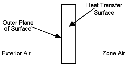
Figure 32. Illustration for Other Side Coefficients
! Example input using temperature schedule
SurfaceProperty:OtherSideCoefficients,
OSCCoef:Zn005:Wall003, !- Name
0, !- Combined Convective/Radiative Film Coefficient {W/m2-K}
0.000000, !- Constant Temperature {C}
1.000000, !- Constant Temperature Coefficient
0.000000, !- External Dry-Bulb Temperature Coefficient
0.000000, !- Ground Temperature Coefficient
0.000000, !- Wind Speed Coefficient
0.000000, !- Zone Air Temperature Coefficient
Zn005Wall003OtherSideTempSched; !- Constant Temperature Schedule Name
! Example input for outside heat transfer coefficient of 1.23, using Tosdb
SurfaceProperty:OtherSideCoefficients,
OSCCoef:Zn005:Wall004, !- Name
1.230000, !- Combined Convective/Radiative Film Coefficient {W/m2-K}
0.000000, !- Constant Temperature {C}
0.000000, !- Constant Temperature Coefficient
1.000000, !- External Dry-Bulb Temperature Coefficient
0.000000, !- Ground Temperature Coefficient
0.000000, !- Wind Speed Coefficient
0.000000, !- Zone Air Temperature Coefficient
, !- Constant Temperature Schedule Name
No, !- Sinusoidal Variation of Constant Temperature Coefficient
24, !- Period of Sinusoidal Variation {hr}
0., !- Previous Other Side Temperature Coefficient
, !- Minimum Other Side Temperature Limit {C}
; !- Maximum Other Side Temperature Limit {C}
By referencing the Other Side Conditions Model statement in the surface statements (i.e. Outside Boundary Condition), the boundary conditions for the outer plane of the mass wall can be connected to the appropriate model for various multi-skin components. The types of multi-skin components that use this object include systems that are mounted to the outside surface using standoffs that create a small air gap – see Figure 33. This type of modeling allows using the usual heat transfer calculations for the underlying surface with other types of multi-skin component models that are available including: unglazed transpired solar collectors, ventilated photovoltaic panels, and naturally ventilated facades.
The boundary condition values are determined dynamically by the program using internal component models. If you want to define other side surface temperatures or convection conditions, then use SurfaceProperty:OtherSideCoefficients instead of this object.
It should be noted that when other side conditions models are used, solar effects are removed from the surface’s outside face heat balance, but are used in modeling the component adjacent to that surface.
In addition, the other side conditions model has been modified to include underground piping system interaction. The PipingSystem:Underground:Domain object represents a mass of ground which may include interaction with, for example, basement surfaces. In this case, the ground model will internally use the other side condition model hook to update boundary conditions for those surfaces which use that other side condition model name reference.
This is the string referenced in the Surface statement that is using OtherSideModel as the Exterior Environment.
This is a string key selection used to identify the type of model that will be used to determine boundary conditions. The only available choices are ”GapConvectionRadiation” or “UndergroundPipingSystemSurface.”
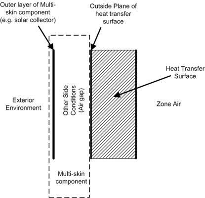
Figure 33. Illustration for Other Side Conditions Model
An example specification is:
SurfaceProperty:OtherSideConditionsModel,
UTSC OSCM ZN11, ! OtherSideConditionsModel Name
GapConvectionRadiation; ! Type of Modeling used to determine Boundary Conditions
This object provides options to change the individual convection model equations for dynamic selection when using AdaptiveConvectiongAlgorithm. This object is only needed to make changes to the default model selections for any or all of the surface categories. This object is for the inside face, the side of the surface facing a thermal zone.
A unique name for the object.
Applies to zone with no HVAC or when HVAC is off. This is for vertical walls. The key choice options include: FohannoPolidoriVerticalWall, ASHRAEVerticalWall, AlamdariHammondVerticalWall, KhalifaEq3WallAwayFromHeat, KhalifaEq6NonHeatedWalls FohannoPolidoriVerticalWall, ISO15099Windows, or UserCurve
The SurfaceConvectionAlgorithm:UserCurve named in this field is used when the previous field is set to UserCurve
Applies to zone with no HVAC or when HVAC is off. This is for horizontal surfaces with heat flow directed for stable thermal stratification. The key choice options include: WaltonStableHorizontalOrTilt, AlamdariHammondStableHorizontal, or UserCurve
The SurfaceConvectionAlgorithm:UserCurve named in this field is used when the previous field is set to UserCurve
Applies to zone with no HVAC or when HVAC is off. This is for passive horizontal surfaces with heat flow for unstable thermal stratification. The key choice options include: WaltonUnstableHorizontalOrTilt, AlamdariHammondUnstableHorizontal, or UserCurve.
The SurfaceConvectionAlgorithm:UserCurve named in this field is used when the previous field is set to UserCurve.
Applies to zone with no HVAC or when HVAC is off. This is for tilted surfaces with heat flow for stable thermal stratification. The key choice options include: WaltonStableHorizontalOrTilt, AlamdariHammondStableHorizontal, or UserCurve
The SurfaceConvectionAlgorithm:UserCurve named in this field is used when the previous field is set to UserCurve.
Applies to zone with no HVAC or when HVAC is off. This is for tilted surfaces with heat flow for unstable thermal stratification. The key choices include: WaltonUnstableHorizontalOrTilt, AlamdariHammondUnstableHorizontal, or UserCurve.
The SurfaceConvectionAlgorithm:UserCurve named in this field is used when the previous field is set to UserCurve.
Applies to zone with no HVAC or when HVAC is off. This is for all window surfaces. The key choice options include: ASHRAEVerticalWall, AlamdariHammondVerticalWall, FohannoPolidoriVerticalWall, KaradagChilledCeiling, ISO15099Windows, or UserCurve.
The SurfaceConvectionAlgorithm:UserCurve named in this field is used when the previous field is set to UserCurve.
Applies to zone with in-floor heating and/or in-ceiling cooling. This is for vertical walls. The key choice options include: ASHRAEVerticalWall, AlamdariHammondVerticalWall, KhalifaEq3WallAwayFromHeat, FohannoPolidoriVerticalWall, ISO15099Windows, or UserCurve.
The SurfaceConvectionAlgorithm:UserCurve named in this field is used when the previous field is set to UserCurve.
Applies to zone with in-floor heating and/or in-ceiling cooling. This is for passive horizontal surfaces with heat flow for stable thermal stratification. The key choice options include: WaltonStableHorizontalOrTilt, AlamdariHammondStableHorizontal, or UserCurve.
The SurfaceConvectionAlgorithm:UserCurve named in this field is used when the previous field is set to UserCurve.
Applies to zone with in-floor heating and/or in-ceiling cooling. This is for passive horizontal surfaces with heat flow for unstable thermal stratification. The key choice options include: WaltonUnstableHorizontalOrTilt, AlamdariHammondUnstableHorizontal, KhalifaEq4CeilingAwayFromHeat, or UserCurve.
The SurfaceConvectionAlgorithm:UserCurve named in this field is used when the previous field is set to UserCurve.
Applies to zone with in-floor heating and/or in-ceiling cooling. This is for a floor with active heating elements. The key choice options include: WaltonUnstableHorizontalOrTilt, AlamdariHammondUnstableHorizontal, AwbiHattonHeatedFloor, or UserCurve
The SurfaceConvectionAlgorithm:UserCurve named in this field is used when the previous field is set to UserCurve.
Applies to zone with in-floor heating and/or in-ceiling cooling. This is for a ceiling with active cooling elements. The key choice options include: WaltonUnstableHorizontalOrTilt, AlamdariHammondUnstableHorizontal, KaradagChilledCeiling, or UserCurve.
The SurfaceConvectionAlgorithm:UserCurve named in this field is used when the previous field is set to UserCurve
Applies to zone with in-floor heating and/or in-ceiling cooling. This is for tilted surfaces with heat flow for stable thermal stratification. The key choice options include: WaltonStableHorizontalOrTilt, AlamdariHammondStableHorizontal, ISO15099Windows, or UserCurve.
The SurfaceConvectionAlgorithm:UserCurve named in this field is used when the previous field is set to UserCurve.
Applies to zone with in-floor heating and/or in-ceiling cooling. This is for tilted surfaces with heat flow for unstable thermal stratification. The key choice options include: WaltonUnstableHorizontalOrTilt, AlamdariHammondUnstableHorizontal, ISO15099Windows, or UserCurve.
The SurfaceConvectionAlgorithm:UserCurve named in this field is used when the previous field is set to UserCurve.
Applies to zone with in-floor heating and/or in-ceiling cooling. This is for all window surfaces. The key choice options include: ASHRAEVerticalWall, AlamdariHammondVerticalWall, ISO15099Windows, or UserCurve.
The SurfaceConvectionAlgorithm:UserCurve named in this field is used when the previous field is set to UserCurve.
Applies to zone with in-wall panel heating. This is for vertical walls that are not actively heated. The key choice options include: ASHRAEVerticalWall, AlamdariHammondVerticalWall, KhalifaEq6NonHeatedWalls, FohannoPolidoriVerticalWall, AlamdariHammondVerticalWall, ISO15099Windows, or UserCurve.
The SurfaceConvectionAlgorithm:UserCurve named in this field is used when the previous field is set to UserCurve.
Applies to zone with in-wall panel heating. This is for vertical walls that are being actively heated. The key choice options include: ASHRAEVerticalWall, AlamdariHammondVerticalWall, KhalifaEq5WallNearHeat, AwbiHattonHeatedWall, FohannoPolidoriVerticalWall, AlamdariHammondVerticalWall, or UserCurve.
The SurfaceConvectionAlgorithm:UserCurve named in this field is used when the previous field is set to UserCurve.
Applies to zone with in-wall panel heating. This is for horizontal surfaces with heat flow directed for stable thermal stratification. The key choice options include: WaltonStableHorizontalOrTilt, AlamdariHammondStableHorizontal, or UserCurve.
The SurfaceConvectionAlgorithm:UserCurve named in this field is used when the previous field is set to UserCurve.
Applies to zone with in-wall panel heating. This is for horizontal surfaces with heat flow directed for unstable thermal stratification. The key choice options include: ASHRAEVerticalWall, WaltonUnstableHorizontalOrTilt, AlamdariHammondUnstableHorizontal, KhalifaEq7Ceiling, or UserCurve
The SurfaceConvectionAlgorithm:UserCurve named in this field is used when the previous field is set to UserCurve.
Applies to zone with in-wall panel heating. This is for tilted surfaces with heat flow for stable thermal stratification. The key choice options include: WaltonStableHorizontalOrTilt, AlamdariHammondStableHorizontal, ISO15099Windows, or UserCurve.
The SurfaceConvectionAlgorithm:UserCurve named in this field is used when the previous field is set to UserCurve
Applies to zone with in-wall panel heating. This is for tilted surfaces with heat flow for unstable thermal stratification. The key choice options include: WaltonUnstableHorizontalOrTilt, AlamdariHammondUnstableHorizontal, ISO15099Windows, or UserCurve.
The SurfaceConvectionAlgorithm:UserCurve named in this field is used when the previous field is set to UserCurve.
Applies to zone with in-wall panel heating. This is for all window surfaces. The key choice options include: ASHRAEVerticalWall, AlamdariHammondVerticalWall, FohannoPolidoriVerticalWall, ISO15099Windows, or UserCurve.
The SurfaceConvectionAlgorithm:UserCurve named in this field is used when the previous field is set to UserCurve.
Applies to zone with convective heater. This is for vertical walls not directly affected by heater. The key choice options include: ASHRAEVerticalWall, AlamdariHammondVerticalWall, KhalifaEq3WallAwayFromHeat, KhalifaEq6NonHeatedWalls, FohannoPolidoriVerticalWall, ISO15099Windows, or UserCurve
The SurfaceConvectionAlgorithm:UserCurve named in this field is used when the previous field is set to UserCurve.
Applies to zone with convective heater. This is for vertical walls that are directly affected by heater. Walls are considered "near" when listed in field set for Fraction of Radiant Energy to Surface. The key choice options include: ASHRAEVerticalWall, AlamdariHammondVerticalWall, KhalifaEq5WallNearHeat, AwbiHattonHeatedWall, FohannoPolidoriVerticalWall, ISO15099Windows, or UserCurve.
The SurfaceConvectionAlgorithm:UserCurve named in this field is used when the previous field is set to UserCurve.
Applies to zone with convective heater. This is for horizontal surfaces with heat flow directed for stable thermal stratification. The key choice options include: WaltonStableHorizontalOrTilt, AlamdariHammondStableHorizontal, or UserCurve.
The SurfaceConvectionAlgorithm:UserCurve named in this field is used when the previous field is set to UserCurve
Applies to zone with convective heater. This is for horizontal surfaces with heat flow directed for unstable thermal stratification. The key choice options include: WaltonUnstableHorizontalOrTilt, AlamdariHammondUnstableHorizontal, KhalifaEq4CeilingAwayFromHeat, KhalifaEq7Ceiling, or UserCurve.
The SurfaceConvectionAlgorithm:UserCurve named in this field is used when the previous field is set to UserCurve.
Applies to zone with convective heater. This is for tilted surfaces with heat flow for stable thermal stratification. The key choice options include: WaltonStableHorizontalOrTilt, AlamdariHammondStableHorizontal, or UserCurve.
The SurfaceConvectionAlgorithm:UserCurve named in this field is used when the previous field is set to UserCurve.
Applies to zone with convective heater. This is for tilted surfaces with heat flow for unstable thermal stratification. The key choice options include: WaltonUnstableHorizontalOrTilt, AlamdariHammondUnstableHorizontal, or UserCurve.
The SurfaceConvectionAlgorithm:UserCurve named in this field is used when the previous field is set to UserCurve.
Applies to zone with convective heater. This is for all window surfaces. The key choice options include: ASHRAEVerticalWall, AlamdariHammondVerticalWall, KhalifaEq3WallAwayFromHeat, FohannoPolidoriVerticalWall, ISO15099Windows, or UserCurve.
The SurfaceConvectionAlgorithm:UserCurve named in this field is used when the previous field is set to UserCurve.
Applies to zone with mechanical forced central air with diffusers. This is for all wall surfaces. The key choice options include: ASHRAEVerticalWall, FisherPedersenCeilingDiffuserWalls, AlamdariHammondVerticalWall, BeausoleilMorrisonMixedAssistedWall, BeausoleilMorrisonMixedOpposingWall, FohannoPolidoriVerticalWall, ISO15099Windows, GoldsteinNovoselacCeilingDiffuserWalls, or UserCurve
The SurfaceConvectionAlgorithm:UserCurve named in this field is used when the previous field is set to UserCurve.
Applies to zone with mechanical forced central air with diffusers. This is for all ceiling surfaces. The key choice options include: FisherPedersenCeilingDiffuserCeiling, BeausoleilMorrisonMixedStableCeiling, BeausoleilMorrisonMixedUnstableCeiling, or UserCurve.
The SurfaceConvectionAlgorithm:UserCurve named in this field is used when the previous field is set to UserCurve.
Applies to zone with mechanical forced central air with diffusers. This is for all floor surfaces. The key choice options include: FisherPedersenCeilingDiffuserFloor, BeausoleilMorrisonMixedStableFloor, BeausoleilMorrisonMixedUnstableFloor, GoldsteinNovoselacCeilingDiffuserFloor, or UserCurve.
The SurfaceConvectionAlgorithm:UserCurve named in this field is used when the previous field is set to UserCurve.
Applies to zone with mechanical forced central air with diffusers. This is for all window surfaces. The key choice options include: ASHRAEVerticalWall, FisherPedersenCeilingDiffuserWalls, BeausoleilMorrisonMixedAssistedWall, BeausoleilMorrisonMixedOpposingWall, FohannoPolidoriVerticalWall, AlamdariHammondVerticalWall, ISO15099Windows, GoldsteinNovoselacCeilingDiffuserWindow, or UserCurve.
The SurfaceConvectionAlgorithm:UserCurve named in this field is used when the previous field is set to UserCurve
The key choice options include: KhalifaEq3WallAwayFromHeat, ASHRAEVerticalWall, FisherPedersenCeilingDiffuserWalls, AlamdariHammondVerticalWall, BeausoleilMorrisonMixedAssistedWall, BeausoleilMorrisonMixedOpposingWall, FohannoPolidoriVerticalWall, ISO15099Windows, GoldsteinNovoselacCeilingDiffuserWalls, or UserCurve.
The SurfaceConvectionAlgorithm:UserCurve named in this field is used when the previous field is set to UserCurve
The key choice options include: WaltonStableHorizontalOrTilt, AlamdariHammondStableHorizontal, or UserCurve.
The SurfaceConvectionAlgorithm:UserCurve named in this field is used when the previous field is set to UserCurve.
The key choice options include: KhalifaEq4CeilingAwayFromHeat, WaltonUnstableHorizontalOrTilt, AlamdariHammondUnstableHorizontal, or UserCurve.
The SurfaceConvectionAlgorithm:UserCurve named in this field is used when the previous field is set to UserCurve.
The key choice options include: WaltonStableHorizontalOrTilt or UserCurve
The SurfaceConvectionAlgorithm:UserCurve named in this field is used when the previous field is set to UserCurve.
The key choice options include: WaltonUnstableHorizontalOrTilt, AlamdariHammondUnstableHorizontal, or UserCurve.
The SurfaceConvectionAlgorithm:UserCurve named in this field is used when the previous field is set to UserCurve.
The key choice options include: ASHRAEVerticalWall, AlamdariHammondVerticalWall, FohannoPolidoriVerticalWall, ISO15099Windows, GoldsteinNovoselacCeilingDiffuserWindow, or UserCurve.
The SurfaceConvectionAlgorithm:UserCurve named in this field is used when the previous field is set to UserCurve
The key choice options include: BeausoleilMorrisonMixedAssistedWall, AlamdariHammondVerticalWall, FohannoPolidoriVerticalWall, ASHRAEVerticalWall, FisherPedersenCeilingDiffuserWalls, GoldsteinNovoselacCeilingDiffuserWalls, or UserCurve.
The SurfaceConvectionAlgorithm:UserCurve named in this field is used when the previous field is set to UserCurve.
The key choice options include: BeausoleilMorrisonMixedOpposingWall, AlamdariHammondVerticalWall, FohannoPolidoriVerticalWall, ASHRAEVerticalWall, FisherPedersenCeilingDiffuserWalls, GoldsteinNovoselacCeilingDiffuserWalls, or UserCurve
The SurfaceConvectionAlgorithm:UserCurve named in this field is used when the previous field is set to UserCurve
The key choice options include: BeausoleilMorrisonMixedStableFloor, WaltonStableHorizontalOrTilt, AlamdariHammondStableHorizontal, or UserCurve
The SurfaceConvectionAlgorithm:UserCurve named in this field is used when the previous field is set to UserCurve.
The key choice options include: BeausoleilMorrisonMixedUnstableFloor, WaltonUnstableHorizontalOrTilt, AlamdariHammondUnstableHorizontal, or UserCurve.
The SurfaceConvectionAlgorithm:UserCurve named in this field is used when the previous field is set to UserCurve.
The key choice options include: BeausoleilMorrisonMixedStableCeiling, WaltonStableHorizontalOrTilt, AlamdariHammondStableHorizontal, or UserCurve.
The SurfaceConvectionAlgorithm:UserCurve named in this field is used when the previous field is set to UserCurve.
The key choice options include: BeausoleilMorrisonMixedUnstableCeiling, WaltonUnstableHorizontalOrTilt, AlamdariHammondUnstableHorizontal, or UserCurve.
The SurfaceConvectionAlgorithm:UserCurve named in this field is used when the previous field is set to UserCurve.
The key choice options include: GoldsteinNovoselacCeilingDiffuserWindow, ISO15099Windows, or UserCurve.
The SurfaceConvectionAlgorithm:UserCurve named in this field is used when the previous field is set to UserCurve.
Options to change the individual convection model equations for dynamic selection when using AdaptiveConvectiongAlgorithm. This object is only needed to make changes to the default model selections for any or all of the surface categories. This object is for the outside face, the side of the surface facing away from the thermal zone.
A unique name for the object
This is for just the wind-driven component of the total convection coefficient. The key choice options include: SimpleCombined, TARPWindward, MoWiTTWindward, DOE2Windward, NusseltJurges, McAdams, Mitchell, Blocken, Emmel, or UserCurve.
The SurfaceConvectionAlgorithm:UserCurve named in this field is used when the previous field is set to UserCurve.
This is for just the wind-driven component of the total convection coefficient. The key choice options include: SimpleCombined, TARPLeeward, MoWiTTLeeward, DOE2Leeward, Emmel, NusseltJurges, McAdams, Mitchell, or UserCurve.
The SurfaceConvectionAlgorithm:UserCurve named in this field is used when the previous field is set to UserCurve.
This is for just the wind-driven component of the total convection coefficient. The key choice options include: SimpleCombined, TARPWindward, MoWiTTWindward, DOE2Windward, NusseltJurges, McAdams, Mitchell, Blocken, Emmel, ClearRoof, or UserCurve.
The SurfaceConvectionAlgorithm:UserCurve named in this field is used when the previous field is set to UserCurve.
This is for just the natural convection portion of the total film coefficient. This is for vertical walls. The key choice options include: ASHRAEVerticalWall, AlamdariHammondVerticalWall, FohannoPolidoriVerticalWall, ISO15099Windows, UserCurve, or None.
The SurfaceConvectionAlgorithm:UserCurve named in this field is used when the previous field is set to UserCurve.
This is for just the natural convection portion of the total film coefficient. This is for horizontal surfaces with heat flow directed for stable thermal stratification. The key choice options include: WaltonStableHorizontalOrTilt, AlamdariHammondStableHorizontal, UserCurve, or None.
The SurfaceConvectionAlgorithm:UserCurve named in this field is used when the previous field is set to UserCurve.
This is for just the natural convection portion of the total film coefficient. This is for horizontal surfaces with heat flow directed for unstable thermal stratification. The key choice optios include: WaltonUnstableHorizontalOrTilt, AlamdariHammondUnstableHorizontal, UserCurve, or None
The SurfaceConvectionAlgorithm:UserCurve named in this field is used when the previous field is set to UserCurve.
This object is used to describe a custom model equation for surface convection heat transfer coefficients. If more than one curve is referenced, or non-blank, then they are all used and the result is the simple addition of all the curve results.
Unique name of input object.
This field controls the nature of the reference temperature used with convection coefficient when calculating the heat flow at the surface. Select one of the three choices: MeanAirTemperature, AdjacentAirTemperature, SupplyAirTemperature. MeanAirTemperature is the typical application for the classic convection model used with the complete mixing of room air. AdjacentAirTemperature applies when used with Roomair models that account for temperature variations within the zone air and directs the model to use the temperature near the surface rather than the average for the entire zone. SupplyAirTemperature directs the model to use the supply air conditions for the heat transfer conditions.
This field contains the name of separate performance curve or table object that describes hc, the convection coefficient, as a function of temperature difference. The curve's "x" is absolute value of delta-T (Surface temperature minus air temperature, (C))
This field contains the name of separate performance curve or table object that describes hc, the convection coefficient, as a function of temperature difference divided by height. The curve's "x" is absolute value of delta-T/Height (Surface temp minus Air temp)/(vertical length scale), (C/m). For an inside face, the vertical length scale is the zone's interior height.
This field contains the name of separate performance curve or table object that describes hc, the convection coefficient, as a function of air change rate. The curve's "x" is mechanical ACH (Air Changes per hour from mechanical air system), (1/hr)
This field contains the name of separate performance curve or table object that describes hc, the convection coefficient, as a function of air change rate divided perimeter scale. Curve's "x" is mechanical system air flow rate (m3/s) divided by zone's length along exterior walls (m).
This object is used to describe a custom model equation for surface convection heat transfer coefficients. If more than one curve is referenced, or non-blank, then they are all used and the result is the simple addition of all the curve results.
Unique name of input object.
This field specifies what sort of wind velocity data should be used in when evaluating the curve in the following field. There are for key choice options. “WeatherFile” directs using the unmodified value from the epw file or design weather data. “HeightAdjust” uses the value from the epw file modified for height above ground, as determined by the z cooridinate, using the site terrain and weather station information. “ParallelComponent” uses the value from the epw file modified to take just the velocity component that is parallel to the surface. “ParallelComponentHeightAdjust” uses the height adjusted wind velocity and then computes the parallel component.
This field contains the name of separate performance curve or table object that describes hf, the forced convection coefficient, as a function of wind speed. The curve's "x" is wind speed as defined by the method chosen in the previous field.
This field contains the name of separate performance curve or table object that describes hn, the natural convection coefficient, as a function of temperature difference. Curve's "x" is absolute value of delta-T (Surface temperature minus air temperature, (C))
This field contains the name of separate performance curve or table object that describes hn, the natural convection coefficient, as a function of temperature difference divided by height. Curve's "x" is absolute value of delta-T/Height (Surface temp minus Air temp)/(vertical length scale), (C/m). For an outside face the vertical length scale is the exterior facade's overall height.
The convection coefficients of each surface, both exterior and interior, are automatically calculated during EnergyPlus execution. These calculations are “governed” by other objects such as the SurfaceConvectionAlgorithm:Inside (overall default), the Zone object’s field called Zone Inside Convection Algorithm (Zone Default), the and the SurfaceConvectionAlgorithm:Outside (overall default), and/or the Zone object’s field called Zone Outside Convection Algorithm (Zone Default). Usually, that will be enough flexibility for most users. However, if you need to match pre-existing convection coefficients (from another program) or are trying to match a test suite of results, you may wish to use the “override” convection coefficients in the following object. This object allows for a single surface to be given specific convection coefficients.
Note that using these in conjunction, in particular, the “Simple” option on either the Outside Convection Algorithm or the Zone Outside Convection Algorithm field will result in a combined coefficient regardless of choice chosen here.
Note that surfaces with “SurfaceProperty:OtherSideCoefficients” cannot use this object with the “outside” coefficient – attempting to do so will cause a severe error; SurfaceProperty:OtherSideCoefficients surfaces can apply an “inside” coefficient. And, surfaces with “Ground” exposure do not use the “outside” coefficient that might be supplied here. Note, too, that some lower boundaries are used regardless by certain surface types (i.e. Window) or certain algorithm types.
This field is the applicable surface name for the user supplied convection coefficient.
For simplicity, the descriptions of these field occur together – however, the fields are used sequentially when put into the IDF file (reference the IDF examples following the descriptions).
This field contains the word “Outside” or “Inside” depending on which location is being described.
The entries can be of several types: Value (simple numeric value), Schedule (name of schedule with the values), the usual key choices for overall models for Outside or Inside (Simple, SimpleCombined, TARP, AdaptiveConvectionAlgorithm etc.), the key choices for individual convection equations used for customizing the adaptive algorithm, or a custom user defined correlation. The field should contain one of the keys listed in the table below along with face they can be applied. The definitions of the models and key choices are discussed under SurfaceConvectionAlgorithm:Inside , SurfaceConvectionAlgorithm:Outside, SurfaceConvectionAlgorithm:Inside:AdaptiveModelSelections, and SurfaceConvectionAlgorithm:Outside:AdaptiveModelSelections.
|
Key choice |
Applies to Inside or Outside |
|
Value |
Both |
|
Schedule |
Both |
|
Simple |
Inside |
|
SimpleCombined |
Outside |
|
TARP |
Both |
|
DOE-2 |
Outside |
|
MoWitt |
Outside |
|
AdaptiveConvectionAlgorithm |
Both |
|
ASHRAEVerticalWall |
Both |
|
WaltonUnstableHorizontalOrTilt |
Both |
|
WaltonStableHorizontalOrTilt |
Both |
|
FisherPedersenCeilingDiffuserWalls |
Inside |
|
FisherPedersenCeilingDiffuserCeiling |
Inside |
|
FisherPedersenCeilingDiffuserFloor |
Inside |
|
AlamdariHammondStableHorizontal |
Both |
|
AlamdariHammondUnstableHorizontal |
Both |
|
AlamdariHammondVerticalWall |
Both |
|
KhalifaEq3WallAwayFromHeat |
Inside |
|
KhalifaEq4CeilingAwayFromHeat |
Inside |
|
KhalifaEq5WallNearHeat |
Inside |
|
KhalifaEq6NonHeatedWalls |
Inside |
|
KhalifaEq7Ceiling |
Inside |
|
AwbiHattonHeatedFloor |
Inside |
|
AwbiHattonHeatedWall |
Inside |
|
BeausoleilMorrisonMixedAssistedWall |
Inside |
|
BeausoleilMorrisonMixedOpposingWall |
Inside |
|
BeausoleilMorrisonMixedStableFloor |
Inside |
|
BeausoleilMorrisonMixedUnstableFloor |
Inside |
|
BeausoleilMorrisonMixedStableCeiling |
Inside |
|
BeausoleilMorrisonMixedUnstableCeiling |
Inside |
|
FohannoPolidoriVerticalWall |
Both |
|
KaradagChilledCeiling |
Inside |
|
ISO15099Windows |
Inside |
|
GoldsteinNovoselacCeilingDiffuserWindow |
Inside |
|
GoldsteinNovoselacCeilingDiffuserWalls |
Inside |
|
GoldsteinNovoselacCeilingDiffuserFloor |
Inside |
|
SimpleCombined |
Outside |
|
NusseltJurges |
Outside |
|
McAdams |
Outside |
|
Mitchell |
Outside |
|
BlockenWindard |
Outside |
|
Emmel |
Outside |
|
ClearRoof |
Outside |
|
UserCurve |
Both |
If the Convection type was “Value”, then this field is filled and contains the simple value to be used. Otherwise, this can be blank.
If the Convection type was “Schedule”, then this field contains the name of a schedule describing the value to be used during the time intervals for the schedule.
The complete IDD definition for the ConvectionCoefficients object follows:
If the Convection type was “UserCurve”, then this field contains the name of a SurfaceConvectionAlgorithm:UserCurve input objct describing the model equations to be used during the time intervals for the schedule.
In IDF usage:
SurfaceProperty:ConvectionCoefficients,
Zn001:Wall001, ! Surface Name
Outside, ! Convection Coefficient 1 Location
Value, ! Convection Coefficient 1 Type
9.8, ! Convection Coefficient 1
, ! Convection Coefficient 1 Schedule Name
, ! Convection Coefficient 1 User Curve Name
Inside, ! Convection Coefficient 2 Location
Schedule, ! Convection Coefficient 2 Type
, ! Convection Coefficient 2 {blank because using schedule}
MyInteriorCC, ! Convection Coefficient 2 Schedule Name
; ! Convection Coefficient 2 User Curve Name
SurfaceProperty:ConvectionCoefficients,
Zn001:Wall002, ! Surface Name
Inside, ! Convection Coefficient 1 Location
Value, ! Convection Coefficient 1 Type
.8, ! Convection Coefficient 1
, ! Convection Coefficient 1 Schedule Name
, ! Convection Coefficient 1 User Curve Name
Outside, ! Convection Coefficient 2 Location
Value, ! Convection Coefficient 2 Type
5.5, ! Convection Coefficient 2
; ! Convection Coefficient 2 User Curve Name
SurfaceProperty:ConvectionCoefficients,
Zn001:Wall003, ! Surface Name
Outside, ! Convection Coefficient 1 Location
Value, ! Convection Coefficient 1 Type
9.8; ! Convection Coefficient 1
The convection coefficients of each surface, both outside and inside, are automatically calculated during EnergyPlus execution. These calculations are “governed” by other objects such as the Inside Convection Algorithm (overall default) and the Zone Inside Convection Algorithm (Zone Default) and the Outside Convection Algorithm (overall default) and/or the Zone Outside Convection Algorithm (Zone Default). Usually, that will be enough flexibility for most users. However, if you need to match pre-existing convection coefficients (from another program) or are trying to match a test suite of results, you may wish to use the “override” convection coefficients in the following object. This object is similar to the preceding “ConvectionCoefficients” object but allows multiple surfaces to be assigned a type with one object entry.
Note that using these in conjunction, in particular, the “Simple” option on either the Outside Convection Algorithm or the Zone Outside Convection Algorithm field will result in a combined coefficient regardless of choice chosen here.
Note that surfaces with “SurfaceProperty:OtherSideCoefficients” cannot use this object with the “outside” coefficient – attempting to do so will ignore OSC surfaces during a multiple surface “apply”; SurfaceProperty:OtherSideCoefficients surfaces can apply an “inside” coefficient. And, surfaces with “Ground” exposure do not use the “outside” coefficient that might be supplied here. Note, too, that some lower boundaries are used regardless by certain surface types (i.e. Window) or certain algorithm types.
This field is the applicable surface name for the user supplied convection coefficient. The allowable surface types are:
n AllExteriorSurfaces (all surfaces that are “external environment” surfaces)
n AllExteriorWindows (all windows that are “external environment” surfaces)
n AllExteriorWalls
n AllExteriorRoofs
n AllExteriorFloors
n AllInteriorSurface (all surfaces that are “internal” surfaces)
n AllInteriorWindows
n AllInteriorCeilings
n AllInteriorFloors
For simplicity, the descriptions of these field occur together – however, the fields are used sequentially when put into the IDF file (reference the IDF examples following the descriptions).
This field contains the word “Outside” or “Inside” depending on which location is being described.
The entries can be of several types: Value (simple numeric value), Schedule (name of schedule with the values), the usual key choices for overall models for Outside or Inside (Simple, SimpleCombined, TARP, AdaptiveConvectionAlgorithm etc.), the key choices for individual convection equations used for customizing the adaptive algorithm, or a custom user defined correlation. The field should contain one of the keys listed in the table below along with face they can be applied. The definitions of the models and key choices are discussed under SurfaceConvectionAlgorithm:Inside , SurfaceConvectionAlgorithm:Outside, SurfaceConvectionAlgorithm:Inside:AdaptiveModelSelections, and SurfaceConvectionAlgorithm:Outside:AdaptiveModelSelections.
|
Key choice |
Applies to Inside or Outside |
|
Value |
Both |
|
Schedule |
Both |
|
Simple |
Inside |
|
SimpleCombined |
Outside |
|
TARP |
Both |
|
DOE-2 |
Outside |
|
MoWitt |
Outside |
|
AdaptiveConvectionAlgorithm |
Both |
|
ASHRAEVerticalWall |
Both |
|
WaltonUnstableHorizontalOrTilt |
Both |
|
WaltonStableHorizontalOrTilt |
Both |
|
FisherPedersenCeilingDiffuserWalls |
Inside |
|
FisherPedersenCeilingDiffuserCeiling |
Inside |
|
FisherPedersenCeilingDiffuserFloor |
Inside |
|
AlamdariHammondStableHorizontal |
Both |
|
AlamdariHammondUnstableHorizontal |
Both |
|
AlamdariHammondVerticalWall |
Both |
|
KhalifaEq3WallAwayFromHeat |
Inside |
|
KhalifaEq4CeilingAwayFromHeat |
Inside |
|
KhalifaEq5WallNearHeat |
Inside |
|
KhalifaEq6NonHeatedWalls |
Inside |
|
KhalifaEq7Ceiling |
Inside |
|
AwbiHattonHeatedFloor |
Inside |
|
AwbiHattonHeatedWall |
Inside |
|
BeausoleilMorrisonMixedAssistedWall |
Inside |
|
BeausoleilMorrisonMixedOpposingWall |
Inside |
|
BeausoleilMorrisonMixedStableFloor |
Inside |
|
BeausoleilMorrisonMixedUnstableFloor |
Inside |
|
BeausoleilMorrisonMixedStableCeiling |
Inside |
|
BeausoleilMorrisonMixedUnstableCeiling |
Inside |
|
FohannoPolidoriVerticalWall |
Both |
|
KaradagChilledCeiling |
Inside |
|
ISO15099Windows |
Inside |
|
GoldsteinNovoselacCeilingDiffuserWindow |
Inside |
|
GoldsteinNovoselacCeilingDiffuserWalls |
Inside |
|
GoldsteinNovoselacCeilingDiffuserFloor |
Inside |
|
SimpleCombined |
Outside |
|
NusseltJurges |
Outside |
|
McAdams |
Outside |
|
Mitchell |
Outside |
|
BlockenWindard |
Outside |
|
Emmel |
Outside |
|
ClearRoof |
Outside |
|
UserCurve |
Both |
If the Convection type was “Value”, then this field is filled and contains the simple value to be used. Otherwise, this can be blank.
If the Convection type was “Schedule”, then this field contains the name of a schedule describing the value to be used during the time intervals for the schedule.
If the Convection type was “UserCurve”, then this field contains the name of a SurfaceConvectionAlgorithm:UserCurve input objct describing the model equations to be used during the time intervals for the schedule.
In IDF usage:
SurfaceProperty:ConvectionCoefficients:MultipleSurface,
AllExteriorWindows, ! Surface Types
Outside, ! Convection Coefficient 1 Location
MoWitt; ! Convection Coefficient 1 Type
Ultimate flexibility and possibly ultimate user confusion can result from the convection coefficient possibilties in EnergyPlus. The objects that control how convection models are assigned to individual surfaces are:
n SurfaceConvectionAlgorithm:Inside
n SurfaceConvectionAlgorithm:Outside
n Zone, Field: Zone Inside Convection Algorithm
n Zone, Field: Zone Outside Convection Algorithm
n SurfaceProperty:ConvectionCoefficients
n SurfaceProperty:ConvectionCoefficients:MultipleSurface
General to Specific, they are assigned in this order:
Table 9. Convection Coefficient Assignment Hierarchy
|
Objects/Description |
Action |
|
SurfaceConvectionAlgorithm:* |
Assigns for all surfaces in the run. |
|
Zone, Fields: Zone * Convection Algorithm |
Trumps global assignment and assigns for all surfaces in Zone. |
|
SurfaceProperty:...:MultipleSurfaces |
Trumps above and assigns for specific types of surfaces. |
|
Two Multiple Surface Assignments overlapping (such as AllExteriorSurfaces vs AllExteriorWalls) |
Order in IDF is now important. Whichever is first gets the cookie and the second gets a warning. |
|
Specific Surface Assignment |
Trumps all Above. |
There are additional objects that provide fine control over the models that get assigned.
n SurfaceConvectionAlgorithm:Inside:AdaptiveModelSelections
n SurfaceConvectionAlgorithm:Outside:AdaptiveModelSelections
n SurfaceConvectionAlgorithm:Inside:UserCurve
n SurfaceConvectionAlgorithm:Outside:UserCurve
Outputs for the User Supplied Convection Coefficients appear as values in the Surface Report Variables (Surface Int Convection Coeff and Surface Ext Convection Coeff). What the program expects to use is shown in the Surface Details report (Output:Surfaces:List, Details;)
When EnergyPlus is set to Display Advanced Variables (Output:Diagnostics, DisplayAdvancedVariables;), then additional report variables are available that indicate the status of convection modeling by identifying which models are in effect at a given time. The adaptive convection algorithms may switch between models over time and the following report variables provide a way to monitor this behavior. These outputs are integer codes and the integer values are explained in tables.
This variable reports how the surface was classified as part of the adaptive convection algorithm for the inside face. The algorithm examines probable flow regimes, heat flow directions, orientations, HVAC equipment connections, and current operating status to assign each surface a category. The numbers in this report are integer codes that correspond to surface categories as described in the following table.
|
Code |
Zone Airflow Regime |
Type of surface |
Heat Flow |
|
1 |
A1 Radiant Heated Floor or Chilled Ceiling |
Vertical Wall |
Any |
|
2 |
A1 Radiant Heated Floor or Chilled Ceiling |
Horizontal |
Stable |
|
3 |
A1 Radiant Heated Floor or Chilled Ceiling |
Horizontal |
Unstable |
|
4 |
A1 Radiant Heated Floor or Chilled Ceiling |
Heated Floor |
Unstable |
|
5 |
A1 Radiant Heated Floor or Chilled Ceiling |
Chilled Ceiling |
Unstable |
|
6 |
A1 Radiant Heated Floor or Chilled Ceiling |
Tilted |
Stable |
|
7 |
A1 Radiant Heated Floor or Chilled Ceiling |
Tilted |
Unstable |
|
8 |
A1 Radiant Heated Floor or Chilled Ceiling |
Window |
Any |
|
9 |
A2 Radiant Wall Heat |
Non-heated Vertical Wall |
Any |
|
10 |
A2 Radiant Wall Heat |
Heated wall |
Any |
|
11 |
A2 Radiant Wall Heat |
Horizontal |
Stable |
|
12 |
A2 Radiant Wall Heat |
Horizontal |
Unstable |
|
13 |
A2 Radiant Wall Heat |
Tilted |
Stable |
|
14 |
A2 Radiant Wall Heat |
Tilted |
Unstable |
|
15 |
A2 Radiant Wall Heat |
Windows |
Any |
|
16 |
A3 Simple Bouyancy |
Vertical Walls |
Any |
|
17 |
A3 Simple Bouyancy |
Horizontal |
Stable |
|
18 |
A3 Simple Bouyancy |
Horizontal |
Unstable |
|
19 |
A3 Simple Bouyancy |
Tilted |
Stable |
|
20 |
A3 Simple Bouyancy |
Tilted |
Unstable |
|
21 |
A3 Simple Bouyancy |
Windows |
Any |
|
22 |
B Convective Zone Heat |
Vertical Walls |
Any |
|
23 |
B Convective Zone Heat |
Vertical Walls near heater |
Any |
|
24 |
B Convective Zone Heat |
Horizontal |
Stable |
|
25 |
B Convective Zone Heat |
Horizontal |
Unstable |
|
26 |
B Convective Zone Heat |
Tilted |
Stable |
|
27 |
B Convective Zone Heat |
Tilted |
Unstable |
|
28 |
B Convective Zone Heat |
Windows |
Any |
|
29 |
C Central Air Diffuser |
Walls |
Any |
|
30 |
C Central Air Diffuser |
Ceiling |
Any |
|
31 |
C Central Air Diffuser |
Floor |
Any |
|
32 |
C Central Air Diffuser |
Windows |
Any |
|
33 |
D Zone Fan Unit |
Walls |
Any |
|
34 |
D Zone Fan Unit |
Horizontal |
Stable |
|
35 |
D Zone Fan Unit |
Horizontal |
Unstable |
|
36 |
D Zone Fan Unit |
Tilted |
Stable |
|
37 |
D Zone Fan Unit |
Tilted |
Unstable |
|
38 |
D Zone Fan Unit |
Windows |
Any |
|
39 |
E Mixed Forced and Bouyancy |
Walls |
Assisting |
|
40 |
E Mixed Forced and Bouyancy |
Walls |
Opposing |
|
41 |
E Mixed Forced and Bouyancy |
Floor |
Stable |
|
42 |
E Mixed Forced and Bouyancy |
Floor |
Unstable |
|
43 |
E Mixed Forced and Bouyancy |
Ceiling |
Stable |
|
44 |
E Mixed Forced and Bouyancy |
Ceiling |
Unstable |
|
45 |
E Mixed Forced and Bouyancy |
Windows |
Any |
This variable reports the specific model equation used to calculate the inside face convection coefficient. This can vary when using the adaptive convection algorithm and so the result of that selection algorithm is reported here. The following table lists the models associated with specific interger codes reported here. The models correspond to key words used in input objects.
|
Report Code |
Related key and model |
|
200 |
UserValue |
|
201 |
UserSchedule |
|
202 |
UserCurve |
|
203 |
ASHRAEVerticalWall |
|
204 |
WaltonUnstableHorizontalOrTilt |
|
205 |
WaltonStableHorizontalOrTilt |
|
206 |
FisherPedersenCeilDiffuserFloor |
|
207 |
FisherPedersenCeilDiffuserCeiling |
|
208 |
FisherPedersenCeilDiffuserWalls |
|
209 |
AlamdariHammondStableHorizontal |
|
210 |
AlamdariHammondVerticalWall |
|
211 |
AlamdariHammondUnstableHorizontal |
|
212 |
KhalifaEq3WallAwayFromHeat |
|
213 |
KhalifaEq4CeilingAwayFromHeat |
|
214 |
KhalifaEq5WallNearHeat |
|
215 |
KhalifaEq6NonHeatedWalls |
|
216 |
KhalifaEq7Ceiling |
|
217 |
AwbiHattonHeatedFloor |
|
218 |
AwbiHattonHeatedWall |
|
219 |
BeausoleilMorrisonMixedAssistingWall |
|
220 |
BeausoleilMorrisonMixedOppossingWall |
|
221 |
BeausoleilMorrisonMixedStableCeiling |
|
222 |
BeausoleilMorrisonMixedUnstableCeiling |
|
223 |
BeausoleilMorrisonMixedStableFloor |
|
224 |
BeausoleilMorrisonMixedUnstableFloor |
|
225 |
FohannoPolidoriVerticalWall |
|
226 |
KaradagChilledCeiling |
|
227 |
ISO15099Windows |
|
228 |
GoldsteinNovoselacCeilingDiffuserWindow |
|
229 |
GoldsteinNovoselacCeilingDiffuserWalls |
|
230 |
GoldsteinNovoselacCeilingDiffuserFloor |
The inside face convection heat transfer calculations can be based on different reference air temperatures. This reference air temperature can vary during the simulation when the adaptive algorithm selects models that use different references. The following table lists the meaning of the integer codes.
|
Report Code |
Reference Air Temperature Method |
|
1 |
Zone mean air temperature |
|
2 |
Surface adjacent air temperature |
|
3 |
Supply air temperature |
This variable reports how the surface was classified as part of the adaptive convection algorithm for the outside face. The algorithm examines the wind direction, heat flow directions and orientations to assign each surface a category. The numbers in this report are integer codes that correspond to surface categories as described in the following table.
|
Report Code |
Surface Classification |
|
101 |
Vertical Wall, Windward |
|
102 |
Vertical Wall, Leeward |
|
103 |
Roof, stable heat flow direction |
|
104 |
Roof, unstable heat flow direction |
These variables report the specific model equation used to calculate the outside face’s convection coefficient. They can vary when using the adaptive convection algorithm and so the results of that selection algorithm are reported in these variables. The following table lists the models associated with specific integer codes that might be reported here. The models correspond to key words used in input objects.
|
Report Code |
Related key and model |
|
300 |
None |
|
301 |
UserValue |
|
302 |
UserSchedule |
|
303 |
UserCurve |
|
304 |
ASHRAESimpleCombined |
|
305 |
NaturalASHRAEVerticalWall |
|
306 |
NaturalWaltonUnstableHorizontalOrTilt |
|
307 |
NaturalWaltonStableHorizontalOrTilt |
|
308 |
SparrowWindward |
|
309 |
SparrowLeeward |
|
310 |
MoWiTTWindward |
|
311 |
MoWiTTLeeward |
|
312 |
DOE2Windward |
|
313 |
DOE2Leeward |
|
314 |
NusseltJurges |
|
315 |
McAdams |
|
316 |
Mitchell |
|
317 |
ClearRoof |
|
318 |
BlockenWindward |
|
319 |
EmmelVertical |
|
320 |
EmmelRoof |
|
321 |
AlamdariHammondVerticalWall |
|
322 |
FohannoPolidoriVerticalWall |
|
323 |
ISO15099Windows |
|
324 |
AlamdariHammondStableHorizontal |
|
325 |
AlamdariHammondUnstableHorizontal |
Advanced/Research Usage:. The internal and external vapor transfer coefficients that are used by the CombinedHeatAndMoistureFiniteElement model are automatically calculated during EnergyPlus execution using information on the convection coefficients. However it is sometimes useful to be able to “override” the calculation and set fixed values of vapor transfer coefficient for a single surface. These coefficients are only used by the CombinedHeatAndMoistureFiniteElement model and will be ignored by other solution algorithms.
This field is the applicable surface name for the user supplied vapor transfer coefficient.
Select ‘yes’ to use the value supplied as the external vapor transfer coefficient
HAMT will use this value to calculate the vapour transfer into and out off the external surface of this surface. Units are kg/Pa.s.m2.
Select ‘yes’ to use the value supplied as the internal vapor transfer coefficient
The CombinedHeatAndMoistureFiniteElement algorithm will use this value to calculate the vapor transfer into and out of the internal surface of this surface. Units are kg/Pa.s.m2.
Below is an example input of vapor transfer coefficients for a surface.
SurfaceProperties:VaporCoefficients,
South wall, !- Surface Name
Yes, !- Constant External Vapor Transfer Coefficient
0.0000000625, !- External Vapor Coefficient Value
Yes, !- Constant Internal vapor Transfer Coefficient
0.00000002; !- Internal Vapor Coefficient Value
This object is used to model a multi-skin exterior heat transfer surface. This is a special case where the outside face is a slightly detached layer forming a naturally ventilated cavity. The actual outer surface is referred to as the baffle. The modeling here assumes that the heat capacity in the outer baffle can be neglected since it is much lower than the underlying mass surface. This object is used with the BuildingSurface:Detailed object where the Heat Transfer surfaces are referred to as the underlying surfaces. The constructions and materials for the BuildingSurface:Detailed object should reflect the construction of just the underlying surface. The SurfaceProperty:ExteriorNaturalVentedCavity object is used to describe the decoupled layer, or baffle, and the characteristics of the cavity and openings for natural ventilation. This object is also used in conjunction with the OtherSideConditionsModel.
The area and orientation are obtained from BuildingSurface:Detailed objects, which are referenced by name. This object can be used to model certain types of photovoltaic mounting configurations such as interlocking roof pavers. If the baffle covers only part of a surface, then that surface should be split into separate BuildingSurface:Detailed objects where one matches the size of the baffle. A single baffle can be associated with as many BuildingSurface:Detailed objects as desired (although if you need to use more than 10 surfaces, then the IDD will need to be extended). The base heat transfer surfaces need not be contiguous nor have the same orientation, but the program will issue warnings if surfaces have widely ranging tilts and azimuths.
Note that the model involves predicting the rates that ambient air moves in and out of the cavity. Accurate modeling of these air flows would be extremely challenging and so the models provided through this object are simplistic engineering models based on discharge coefficients that are sensitive to wind and bouancy effects. The accuracy depends on the values for, and applicability of, the discharge coefficients and unfortunately little research is available to help characterize these. The models should be considered rudimentary and the user is encouraged to explore different values for the coefficients in attempts to bound the importance of natural ventilation for the cavities. See the Engineering Reference for more details.
This field contains a unique name for the ventilated cavity.
This field contains the name of an SurfaceProperty:OtherSideConditionsModel object declared elsewhere in the input file. This will connect the baffle and ventilated cavity to the exterior boundary conditions for the underlying heat transfer surface.
This field is used to enter an area fraction for what part of the baffle consists of openings. The area of the openings will set to the product of this field and the sum of the area of the underlying surfaces.
This field is used to enter the thermal emissivity of the baffler. This surface property is for longwave infrared radiation. The property is used for both sides of collector. Most painted materials have an emissivity of 0.9.
This field is used to enter the solar absorbtivity of the baffle. This surface property is for shortwave, solar radiation. The property is used for the front side of the baffle that faces the environment. Darker colors have a higher absorptivity. While black is the highest performance, other colors might be used to match the color scheme of the rest of the façade.
This field is used to enter a nominal height scale for prediction ventilation induced by bouancy. This value (![]() ) is defined as the height from the midpoint of the lower opening to the neutral pressure level. Increasing the value will increase the ventilation rate due to buoyancy.
) is defined as the height from the midpoint of the lower opening to the neutral pressure level. Increasing the value will increase the ventilation rate due to buoyancy.
This field is used to enter a nominal gap thickness for the collector. This distance value is only used when the collector is near horizontal to determine a length scale in the vertical direction for buoyancy calculations. For example, if the collector is mounted on a flat roof, its tilt-adjusted height is zero and the program will use this gap thickness as a length scale rather than the height from the previous field.
This field is used to enter a factor that accounts for the extra surface area resulting from and uneven baffle surface. Corrugations may be present to help stiffen the baffle or ventilated roofing tiles may have more surface are for convection heat transfer than the underlying surface. The projected surface area is obtained by the program from the (flat) underlying surfaces. If the baffle is flat then this ratio is 1.0. If the baffle is corrugated, then this ratio will be greater than one with a typical value might be 1.165.
This field is used to describe the relative roughness of the baffle material. This field is similar to one in the Material object. This parameter only influences the convection coefficients, more specifically the exterior convection coefficient. A special keyword is expected in this field with the options being “VeryRough”, “Rough”, “MediumRough”, “MediumSmooth”, “Smooth”, and “VerySmooth” in order of roughest to smoothest options.
This field is used to enter a value for the coefficient used to determine natural air exchanges from wind. Wind will cause exterior air to move in and out of the cavity. Cv is an arbitrary coefficient used to model the effectiveness of openings and depends on opening geometry and the orientation with respect to the wind. Cv should probably be in the range 0.05 to 0.65. Increasing Cv will increase the amount of natural ventilation. The following equation shows how Cv is used in the program to predict the volumetric flow rate due to wind:
![]()
This field is used to enter a value for the coefficient used to determine natural air exchanges from buoyancy. Stack or buoyancy effects will cause exterior air to move in and out of the cavity. Cd is an arbitrary discharge coefficient that depends on the geometry of the opening. Cd should probably be in the range 0.1 to 1.0. Increasing Cd will increase the amount of natural ventilation. The following equations show how Cd is used in the program to predict the volume flow rate due to buoyancy:
![]() (if
(if ![]() )
)
![]() (if
(if ![]() and baffle is vertical)
and baffle is vertical)
where ![]() is the value input into the field above for the height scale for bouyancy-driven ventilation.
is the value input into the field above for the height scale for bouyancy-driven ventilation.
The remaining fields are used to name the BuildingSurface:Detailed objects that are associated with the exterior naturally vented cavity. These are the underlying heat transfer surfaces and are defined elsewhere in the input file. These surfaces should all specify OtherSideConditionsModel as their exterior environment. The input object can currently accommodate up to ten surfaces, but it is extensible by modifying the Energy+.idd entry.
An example IDF entry is
SurfaceProperty:ExteriorNaturalVentedCavity,
PVRoofPaverExtVentCav1 , ! Name
PVRoofPaverSystem1, ! OtherSideConditionsModel Object Name
0.02, ! Area Fraction of Openings
0.9, ! Thermal Emissivity of Exterior Baffle Material
0.92, ! Solar Absorbtivity of Exterior Baffle
0.05, ! Height scale for bouyancy-driven ventilation
0.05, ! Effective Thickness of Cavity Behind Exterior Baffle
0.97, ! Ratio of Actual surface area to projected surface area
Smooth , ! Roughness of collector
0.1 , ! Cv, Effectiveness for perforations with respect to Wind
0.5 , ! Cd, Discharge Coefficient for Openings with respect to bouyancy-driven flow
Zn001:Roof001 ; ! Surface Name
In addition to related output that can be obtained for all surfaces, these outputs are available for exterior naturally vented cavity configurations:
HVAC,Average, Exterior Cavity Drybulb Temperature[C]
HVAC,Average, Exterior Baffle Temperature[C]
HVAC,Average, Exterior Cavity Air Changes per Hour Passive[ACH]
HVAC,Average, Exterior Cavity Total Natural Vent Mass Flow[kg/s]
HVAC,Average, Exterior Cavity Total Natural Vent Mass Flow from Wind[kg/s]
HVAC,Average, Exterior Cavity Total Natural Vent Mass Flow from Bouyancy[kg/s]
The temperature of air inside the cavity behind the baffle.
The surface temperature of the exterior baffle material itself.
The rate of natural ventilation air exchange between the plenum and ambient when the collector is inactive in Air Changes per Hour.
The mass flow rate of natural ventilation air exchange between the plenum and ambient when the collector is inactive.
The part of mass flow rate of natural ventilation air exchange between the plenum and ambient when the collector is inactive due to wind-driven forces.
The part of mass flow rate of natural ventilation air exchange between the plenum and ambient when the collector is inactive due to bouyancy-driven forces.
This object provides a simple method of altering the footprint geometry of a model. The intent is to provide a single parameter that can be used to reshape the building description contained in the rest of the input file. This object was implemented for use in parametric massing studies and with the optimization program GenOpt. Although building footprint is often constrained in practice, analysts may find this object useful for investigating how building form impacts daylighting and solar gains on the east and west facades with out having to change all of the surface geometry input.
Aspect Ratio is defined as the overall length in the East-West direction divided by the overall length in the North-South direction.
This object should be used with considerable care since it will completely alter the geometry modeled by EnergyPlus and may have unintended side effects. The surface areas of all horizontal surfaces may change radically with corresponding changes in Zone floor areas. The total floor area will not change but individual horizontal surfaces will gain and loose area. Vertical surfaces will have the same height but will gain and lose length. Lighting and electrical equipment design levels for individual zones will likely have a different energy per unit area in the transformed geometry.
The surface geometry must be set to Relative, see GlobalGeometryRules. Of course, the coordinates must be entered in relative coordinates as well.
Since windows in EnergyPlus need to be rectangular, it is possible to define a horizontal window (skylight) that once transformed is no longer rectangular and will cause EnergyPlus to halt. To avoid this problem, horizontal windows should be defined orthogonal to the Cardinal directions and building rotation (see Building) used to orient the final form with respect to North.
The object doesn’t create any specific output, but the results of using it can be understood by viewing DXF output files. Figure 34 shows an example of a building that has been morphed using the Aspect Ratio Transform object. Using this object allowed the same geometry input to generate both of the models represented in by their DXF output files.
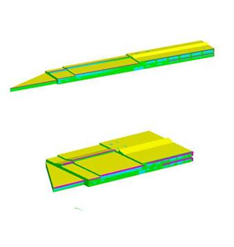
Figure 34. Example of Geometry Transform -- Aspect Ratio
This field specifies the plane that the geometry transform should act on. It is currently restricted to altering the horizontal footprint of a building and must be set to “XY.”
This field specifies the aspect ratio of the building geometry described in the rest of the input file. It is used to scale the new aspect ratio. If this field is set to 1.0, then the altered building will not necessarily have the new aspect ratio defined in the next field.
This field specifies the aspect ratio that the building described in the rest of the input file will be changed to.
EnergyPlus has two options for specifying the thermal radiation exchange view factors between surfaces in a zone: the approximate option and the user input option. Because the actual geometric arrangement within a zone is very complex, the approximate method of including thermal mass and other forced exchanges is more realistic than trying to come up with “exact” view factors. However, in some research situations it might be desirable to have control of the view factors used. For this reason, a user input mode has been included in EnergyPlus. The two modes are described in the next sections.
The first option produces approximate results and uses an area weighted scheme to calculate "view factors" between surfaces within a thermal zone. Each surface uses the total area that it can “see” among the other surfaces. The approximate view factor from this surface to each other surface is then the area of the receiving surface over the sum of areas that are visible to the sending surface.
In order to account in some limited way for the fact that certain surfaces will not see each other, several assumptions have been built into this view factor approximation. First, a surface cannot see itself. Second, surfaces with approximately the same azimuth (facing direction) and tilt ("same" being within a built in limit) will not see each other. This means that a window will not see the wall that it is placed on, for example. Third, floors cannot see each other. Fourth, if the surface is a floor, ceiling, roof, or internal mass, the rule for the same azimuth and tilt eliminating radiant exchange between surfaces is waived when the receiving surface is floor, roof, ceiling, or internal mass as long as both surfaces are not floors.
Note that this does not take into account that surfaces may be "around the corner" from each other and in reality not see each other at all. Rooms are assumed to be convex rather than concave in this method.
To summarize, using the Surface “Class”, the approximate view factors have:
1. No surface sees itself.
2. No Floor sees another floor.
3. All other surface types see Internal Mass.
4. All other surface types see floors.
5. Floors always see ceilings.
6. Floors always see roofs.
7. All other surfaces whose tilt or facing angle differences are greater than 10 degrees see each other.
If geometry is correct, conditions 1,3, and 7 should take care of all surfaces, but the other conditions supply common sense when the geometry is incorrect. More information about the EnergyPlus view factor calculation is contained in the Engineering Reference document.
The second option for specifying view factors requires user input values. These should be used with care in research or special situations. Two objects are available for this: ZoneProperty:UserViewFactors and ZoneProperty:UserViewFactors:bySurfaceName.
One method for entering user view factors is to use the object named ZoneProperty:UserViewFactors. They are identified by their row and column number in the view factor array. In other words, the view factor is traditionally Fi,j, and the value along with i and j are specified in the idf.
An example idf object is shown below. Note that the alpha field is the zone name for which the view factors apply.
ZoneProperty:UserViewFactors,
! example with unrealistic view factors that show
! a scheme for checking the input.
core, ! zone name
1,1,.11, ! triple of i, j, and Fij
1,2,.12,
1,5,.15,
2,2,.22,
2,3,.23,
4,2,.42,
4,5,.45,
5,1,.51,
5,6,.56,
3,6,.36,
4,6,.46,
6,5,.65,
6,4,.64;
In order to get user view factors ready for inclusion in an input file, several steps much be taken. First, because EnergyPlus has a data structure for zones that only is defined at initialization, it is necessary to use EnergyPlus to determine the surface numbers (i,j) before a UserViewFactors object can be constructed. This is done by making a run with a special object. This takes the form:
Output:Reports,Surfaces,ViewFactorInfo;
This will trigger EnergyPlus to produce a special output section in the file eplusout.eio. This file, which is csv format, can be opened in Excel, and will show detailed information about the surfaces in all the zones. The example and procedure for using this information is shown in the Output Details and Examples Document.
The second method of entering user view factors is slightly more straightforward in that you do not need to run EnergyPlus first to get the surface numbers for the entry.
This field is the zone name for the view factors.
This field specifies the name of the “from surface”.
This field specifies the name of the “to surface”.
This value is the view factor for “from Surface” to “to Surface”.
An IDF Example:
ZoneProperty:UserViewFactors:bySurfaceName,Lshaped Zone,
Lshaped Zone:South Wall,Lshaped Zone:South Wall,0.000000,
Lshaped Zone:South Wall,Lshaped Zone:East Wall,0.101310,
<snip>
The following objects may be included in an EnergyPlus input IDF file but are handled by the Slab preprocessor:
n GroundHeatTransfer:Slab:Materials
n GroundHeatTransfer:Slab:MatlProps
n GroundHeatTransfer:Slab:BoundConds
n GroundHeatTransfer:Slab:BldgProps
n GroundHeatTransfer:Slab:Insulation
n GroundHeatTransfer:Slab:EquivalentSlab
n GroundHeatTransfer:Slab:AutoGrid
n GroundHeatTransfer:Slab:ManualGrid
n GroundHeatTransfer:Slab:XFACE
n GroundHeatTransfer:Slab:YFACE
n GroundHeatTransfer:Slab:ZFACE
The following objects may be included in an EnergyPlus input IDF file but are handled by the Basement preprocessor:
n GroundHeatTransfer:Basement:SimParameters
n GroundHeatTransfer:Basement:MatlProps
n GroundHeatTransfer:Basement:Insulation
n GroundHeatTransfer:Basement:SurfaceProps
n GroundHeatTransfer:Basement:BldgData
n GroundHeatTransfer:Basement:Interior
n GroundHeatTransfer:Basement:ComBldg
n GroundHeatTransfer:Basement:EquivSlab
n GroundHeatTransfer:Basement:EquivAutoGrid
n GroundHeatTransfer:Basement:AutoGrid
n GroundHeatTransfer:Basement:ManualGrid
n GroundHeatTransfer:Basement:XFACE
n GroundHeatTransfer:Basement:YFACE
n GroundHeatTransfer:Basement:ZFACE
The documentation both the Slab and Basement objects appear in the AuxiliaryPrograms document under the “Ground Heat Transfer in EnergyPlus” heading.
The only object described in this section is the control object which activates the use of the preprocessor.
The GroundHeatTransfer:Control object determines if the Slab and Basement preprocessors are going to be executed. When a Slab or Basement run is performed the results are saved in files with extensions .SLAB or .BSMT so that they do not need to be rerun if no input changes are made to the GroundHeatTransfer:Slab or GroundHeatTransfer:Basement objects.
This alpha field is the name of the GroundHeatTransfer:Control object. It is used as an identifier.
The field can either be Yes or No and defaults to No. It is used to control whether the Basement preprocessor program is executed. If it has been previously executed the results are stored in the .BSMT file and do not necessary need to be run again unless the GroundHeatTransfer:Basement objects have changed.
The field can either be Yes or No and defaults to No. It is used to control whether the Slab preprocessor program is executed. If it has been previously executed the results are stored in the .SLAB file and do not necessary need to be run again unless the GroundHeatTransfer:Slab objects have changed.
The group of input objects described in this section is used to account for non-uniform room air temperatures that may occur within the interior air volume of a zone. Room air modeling was added to EnergyPlus starting with Version 1.2. Although there are many types of analyses (comfort, indoor air quality, etc) that might benefit from localized modeling of how room air varies across space, only the temperature distribution of room air within the zone is currently addressed in EnergyPlus. This allows surface heat transfer and air system heat balance calculations to be made taking into account natural thermal stratification of air and different types of intentional air distribution designs such as under-floor and side-wall displacement ventilation that purport to extract room air at higher-than-mean temperatures. Note that EnergyPlus does not have completely general methods of modeling room air that are applicable to every conceivable type of airflow that might occur in a zone. Such models (e.g. RANS-CFD) are too computationally expensive to use with EnergyPlus for the foreseeable future. The models that are available in EnergyPlus offer only limited modeling capabilities for select room airflow configurations. Also note that because the complete mixing model for room air has long been the standard in building energy simulation, there is not currently a consensus on how to best model non-uniform air temperatures in buildings. Therefore, it is up to the user to have a good understanding of when, where, and how to apply the room air models available in EnergyPlus. The rest of this section provides some guidance in the way of examples and further discussion of the models available in EnergyPlus.
EnergyPlus offers the different types of air models listed in the table below along with the input objects associated with the use of that model.
Table 10. Summary of Room Air Models
|
Air Model Key |
Air model Algorithm |
Applicability |
Input Objects Required |
|
Mixing |
Well-Mixed |
All zones |
None, default |
|
UserDefined |
User Defined |
All zones |
‘RoomAirModelType’, ‘RoomAir:TemperaturePattern:UserDefined’,’ RoomAir:TemperaturePattern:***’ |
|
OneNodeDisplacementVentilation |
Mundt |
displacement ventilation |
‘RoomAirModelType’, ‘RoomAirSettings:OneNodeDisplacementVentilation’, ‘RoomAir:Node’’ |
|
ThreeNodeDisplacementVentilation |
UCSD Displacement Ventilation |
displacement ventilation |
‘RoomAirModelType’ , ‘RoomAirSettings:ThreeNodeDisplacementVentilation’ |
|
UnderFloorAirDistributionInterior |
UCSD UFAD Interior Model |
Interior zones served by a UFAD system |
‘RoomAirModelType’, ‘RoomAirSettings:UnderFloorAirDistributionInterior’ |
|
UnderFloorAirDistributionExterior |
UCSD UFAD Exterior Model |
Exterior zones served by a UFAD system |
‘RoomAirModelType’,,’ RoomAirSettings:UnderFloorAirDistributionExterior’ |
|
CrossVentilation |
UCSD Cross Ventilation |
cross ventilation |
‘RoomAirModelType’ , ‘RoomAirSettings:CrossVentilation’ |
EnergyPlus uses the RoomAirModelType object to determine which air model is available for use in a given zone during the simulation. If no RoomAirModelType object is specified (for each zone or the whole building), then EnergyPlus will run with the conventional, completely mixing air model (for each zone or the whole building). Include a RoomAirModelType for each zone that the user wants modeled using a more detailed method. Currently only a single RoomAirModelType object can be specified for each zone; you cannot switch between models during a simulation. However, the UCSD Displacement, Cross Ventilation and UFAD models switch from displacement to mixing ventilation when the operating conditions do not give rise to unmixed flow. The following parameters are fields required by the RoomAirModelType object.
This alpha field is the air model name selected by user. It is used as an identifier
This alpha field indicates the unique name of a Zone object defined elsewhere in the input file. The type of room air model selected will be applied to this zone.
This alpha field indicates the room-air model used for the specified zone. Currently, there are three options for different air models. Entering the keyword ‘Mixing’ specifies the conventional complete-mixing air model. Note that Mixing is the default and no RoomAirModelType object would be needed to use the complete-mixing model. Entering the keyword ‘UserDefined ‘specifies the User Defined Room Air Temperature Patterns. Entering the keyword ‘OneNodeDisplacementVentilation ‘specifies the Mundt one node displacement ventilation air model for displacement ventilation. Entering the keyword ‘ThreeNodeDisplacementVentilation‘ specifies the three-node displacement ventilation model developed by the University of California, San Diego (UCSD DV). Entering the keyword ‘CrossVentilation’ specifies the two-zone cross ventilation model developed by the University of California, San Diego (UCSD CV). Entering the keyword ‘UnderFloorAirDistributionInterior‘ specifies the two-node interior zone under floor air distribution model developed by the University of California, San Diego (UCSD UFI). Entering the keyword ‘UnderFloorAirDistributionExterior‘ specifies the two-node exterior zone under floor air distribution model developed by the University of California, San Diego (UCSD UFE).
This alpha field indicates how air temperatures predicted by the air models are used by the surface heat balance calculation. Two different coupling schemes are available: Direct (also known as T-couple) or Indirect (DT-couple). In general, indirect coupling is more suited to situations where room air is well controlled and/or the room air model is less robust. Direct coupling is more suited for floating zone air temperatures and/or accurate room air models.
The Mundt model can use either coupling scheme; the UCSD DV, UCSD CV, UCSD UFI, and UCSD UFE models ignore this field and use direct coupling.
Input either Direct or Indirect
An example idf entry follows
RoomAirModelType,
MOD1, !- Room-Air Model Name
ZONE ONE, !- Zone Name
ThreeNodeDisplacementVentilation, !- Room-Air Modeling Type
Direct; !- Air Temperature Coupling Strategy
This object is used to explicitly define temperature patterns that are to be applied to the mean air temperature within a thermal zone. This Room Air modeling option is made available for a number of reasons. It allows modeling the consequences of air temperature variations during the design phase when little information is available about the specifics of the air distribution system or positioning of various loads. This option can be used to evaluate the energy implications of different design targets for the temperature patterns. It also provides a method of modeling the annual energy use implications for air temperature distributions determined using separate analyses or measurements. For example, this option could be used to understand the annual energy implications of an air distribution system that has been previously analyzed using Computational Fluid Dynamics.
This approach differs from the other Room Air modeling in that the static temperature pattern is not really modeled so that it will respond to conditions that develop during the simulation. More sophisticated dynamic Room Air models will adjust the temperature pattern based on various factors, such as air system flow rate, floor temperature, or rates of internal heat gains. The user-defined temperature distribution patterns are fixed at the beginning and EnergyPlus simply provides results that include the implications of those patterns. This user-defined distribution option may also be useful for checking dynamic Room Air models by using “bounding” analysis.
Note that using this object carries a certain degree of responsibility. It would be very easy to define a pattern that is non-physical and will lead to erroneous results. The user-defined temperature distributions should (probably) be balanced about the mean so that basic conservation of energy laws are not violated.
This field provides a unique name for this object.
This field provides the unique name of a zone described elsewhere in the file.
This field provides the name of a schedule that will determine if this model is available. When not available the room air is modeled as completely mixed. When it is available, then a user-defined temperature distribution will be applied. This schedule should be set to “1.0” when model is available and “0.0” when the model is not to be used.
This field provides the name of schedule that will be used to control which user-defined RoomAir temperature pattern will be applied at any given time. This schedule needs to have integer values that are closely coordinated with those defined as the second field in one of the RoomAir:TemperaturePattern:* objects described below. These schedule values provide the link to the actual patterns to be used throughout the day. This allows controlling which user-defined pattern is used at different times during the simulation. For example, one could use one pattern when the air system is scheduled to be on, and a different pattern when the air system is schedule to be off. Or if the user has knowledge of how the air temperature pattern changes over the course of day in response to changing thermal loads, then this schedule can be used to control when individual patterns are used. For example, a control schedule could use a pattern designated as number 100 from 18:00 to 6:00, pattern number 200 from 6:00 to 12:00, and pattern number 300 from 12:00 to 18:00.
An example of this object is
RoomAir:TemperaturePattern:UserDefined,
Ground Floor South Air Temp Contrls , ! Name
ZN2_S_1 , ! Zone Name
Always_on , ! Availability Schedule Name
Roomair Pattern 1; ! Pattern Control Schedule Name
This object is used to model room air with a fixed temperature gradient in the vertical direction. This fixed-slope method is about the simplest distribution pattern.
In addition to the vertical temperature gradient, there are three other parameters included in the pattern that are important. The first two might affect how the air system conditioning the room is operated. The first describes the temperature difference between the mean air temperature and the point where the sensor of a drybulb thermostat is situated. The second describes the temperature difference between the mean and the point where system air is being extracted from the zone. This is considered important because the changes in temperature difference between supply and return can affect how an air system is controlled to meet the loads. The third parameter can affect the zone air heat balance by altering the temperature of the air leaving the zone through exhaust fans.
One example of a source of input data for the vertical temperature gradient is ANSI/ASHRAE Standard 55-2004 Thermal Environmental Conditions for Human Occupancy. Table 5.2.4.3 in this Standard specifies an allowable vertical temperature difference between head level and ankle level of 3ºC (5ºF). If we assume a head to ankle length scale of 1.5 m (5 ft), this leads to a temperature gradient of 3ºC/1.5m, or 2.0 ºC/m.
This field provides a unique name for this object.
This field should contain an integer value that is unique among all other RoomAir:TemperaturePattern:* objects. The value used here needs to be in the Pattern Control Schedule for those times when this pattern is to be used for the Room Air Temperature Distribution.
This field specifies the temperature difference between where the thermostat is situated and the mean air temperature.
This field specifies the temperature difference between the air leaving the zone and returning to the air system and the mean air temperature.
This field specifies the temperature difference between the air leaving the zone and being exhausted out of the building and the mean air temperature.
This field specifies the gradient, or slope, of temperature changes in the vertical direction in ºK/m.
An example of this object is:
RoomAir:TemperaturePattern:ConstantGradient,
half C per Meter, ! Name
10005, ! Control Integer for Pattern Control Schedule Name
0.0, ! Thermostat Offset (Temp at thermostat- Mean Air Temp) [C]
1.0, ! Return Air Offset (Tleaving - Mean Air Temp ) [C]
1.0, ! Exhaust Air Offset (Texhaust - Mean Air Temp) [C]
0.5; ! Temperature Gradient Deg C/m
This object provides various controls over the value of the gradient used for determining the pattern of room air temperatures. It is similar to previous object RoomAir:TemperaturePattern:ConstantGradient object but simplifies the potentially arduous task of preparing and scheduling a large number of those objects. With this object, two different gradients are entered and user is given several options for controlling how the program will interpolate between the two bounds. The user inputs the height of the location of thermostat, return air, and exhaust air in meters rather than the temperature offset.
This field provides a unique name for this object.
This field should contain an integer value that is unique among all other RoomAir:TemperaturePattern:* objects. The value used here needs to be in the Pattern Control Schedule for those times when this pattern is to be used for the Room Air Temperature Distribution.
This field specifies the distance above the floor where the thermostat is situated. This height is used by the model to determine the thermostat temperature relative to the mean air temperature by applying the gradient.
This field specifies the distance above the floor where the air leaves the zone and returns to the air system. and the mean air temperature. This height is used by the model to determine the return air temperature relative to the mean air temperature by applying the gradient.
This field specifies the distance above the floor where the air leaves the zone and enters and exhaust device such as an exhaust fan. This height is used by the model to determine the exhaust air temperature relative to the mean air temperature by applying the gradient.
This field specifies the gradient, or slope, of temperature changes in the vertical direction in ºC/m.
This field specifies the gradient, or slope, of temperature changes in the vertical direction in ºC/m.
This field specifics how the program will vary between the two gradients. Select one of the following keywords to choose the simulation data used to scale: ‘Outdoor Environment Drybulb Temperature’, ‘Zone Drybulb Temperature’, ‘Delta Outdoor and Zone Temperature’, ‘Sensible Cooling Load’, and ‘Sensible Heating Load’. These are explained in detail below. All of these options have several things in common. They are essentially hard-coded. There is no support for a general method. The interpolation scheme is based on some variable that might reasonably be expected to correlate with gradient changes. This variable’s current value is used to continually adjust the value of the vertical gradient for room air temperature.
OutdoorDryBulbTemperature: This key directs the program to interpolate between upper and lower values of the vertical gradient based on the outdoor air temperature. If the outdoor temperature exceeds the upper limit set in the next field, then the gradient entered in the ‘Temperature Gradient Upper Bound’ field is used. Similarly if the outdoor air temperature is below the value set in the ‘Lower Temperature’ field, then the gradient entered in the ‘Temperature Gradient Lower Bound’ is used. For outdoor temperatures that lie between the upper and lower bounds, the gradient is determined by linear interpolation between the two.
ZoneDryBulbTemperature: This key directs the program to interpolate between upper and lower values of the vertical gradient based on the mean zone air temperature. If the mean zone air temperature exceeds the upper limit set in the next field, then the gradient entered in the ‘Temperature Gradient Upper Bound’ field is used. Similarly if the mean zone air temperature is below the value set in the ‘Lower Temperature’ field, then the gradient entered in the ‘Temperature Gradient Lower Bound’ is used. For mean zone air temperatures that lie between the upper and lower bounds, the gradient is determined by linear interpolation between the two.
ZoneAndOutdoorTemperatureDifference: This key directs the program to interpolate between upper and lower values of the vertical gradient based on the difference between the outdoor environment and the mean zone air temperature. If the temperature difference exceeds the upper limit set in the next field, then the gradient entered in the ‘Temperature Gradient Upper Bound’ field is used. Similarly if the temperature difference is below the value set in the ‘Lower Temperature’ field, then the gradient entered in the ‘Temperature Gradient Lower Bound’ is used. For temperature differences that lie between the upper and lower bounds, the gradient is determined by linear interpolation between the two.
SensibleCoolingLoad: This key directs the program to interpolate between upper and lower values of the vertical gradient based on the sensible cooling load. If the cooling load exceeds the upper limit set in the next field, then the gradient entered in the ‘Temperature Gradient Upper Bound’ field is used. Similarly if the cooling load is below the value set in the ‘Lower Temperature’ field, then the gradient entered in the ‘Temperature Gradient Lower Bound’ is used. For cooling loads that lie between the upper and lower bounds, the gradient is determined by linear interpolation between the two.
SensibleHeatingLoad: This key directs the program to interpolate between upper and lower values of the vertical gradient based on the sensible heating load. If the heating load exceeds the upper limit set in the next field, then the gradient entered in the ‘Temperature Gradient Upper Bound’ field is used. Similarly if the heating load is below the value set in the ‘Lower Temperature’ field, then the gradient entered in the ‘Temperature Gradient Lower Bound’ is used. For heating loads that lie between the upper and lower bounds, the gradient is determined by linear interpolation between the two.
This field is used to enter the upper bound on temperature values in Celsius. It is required for the interpolation modes based on temperature.
This field is used to enter the lower bound on temperature values in Celsius. It is required for the interpolation modes based on temperature.
This field is used to enter the upper bound on heat rate values. It is required for the interpolation modes based on load. Both heating and cooling loads are entered as positive numbers (in watts).
This field is used to enter the lower bound on heat rate values. It is required for the interpolation modes based on load. Both heating and cooling loads are entered as positive numbers (in watts).
An example of this object follows. This pattern will apply no gradient (effectively the mixing model) if zone air temperatures are 22.5 C or lower. It will apply a gradient of 1 degree Celsius per meter if zone temperatures are 26.0 C or higher. For zone air temperatures between 22.5 and 26.0 it will determine the gradient by linear interpolation and use a gradient between 0.0 and 1.0 C/m depending on where the zone air temperature is in the range.
RoomAir:TemperaturePattern:TwoGradient,
Mixed to one C per M by Zone DB, ! Name
2002, ! Control Integer for Pattern Control Schedule
1.1, ! Thermostat Height meters
4.5, ! Return Air Height
3.5, ! Exhaust Air Height
0.0, ! Temperature Gradient Lower Bound Deg C/m
1.0, ! Temperature Gradient Upper Bound Deg C/m
ZoneDrybulbTemperature, ! Gradient Interpolation Mode
26.0, ! Upper Temperature [C]
22.5, ! Lower Temperature [C] !
, ! Upper Heat Rate [W]
; ! Lower Heat Rate [W]
This object defines a distribution pattern for air temperatures relative to the current mean air temperature as a function of height. The height, referred to as Zeta, is non-dimensional by normalizing with the zone ceiling height. (The actual zone ceiling height can be explicitly entered in the ‘Zone’ object but if not it is calculated by EnergyPlus from the surfaces attached to the zone.) The temperature differences are not non-dimensional and remain in units of degrees Celsius.
An example of a vertical temperature pattern is shown in the figure below. The pattern itself is treated as a piecewise, linear model of air temperature as a function of height. This Zeta-DeltaTai curve, or lookup table, is then mapped to surfaces defined elsewhere in the file. The centroid of each surface and zone ceiling height are used to automatically assign Zeta values within the program. The zone named in the referencing RoomAir:TemperaturePattern:UserDefined object is used to determine which surfaces will be associated with the pattern when it is applied. A single pattern object can be reused for multiple zones and times.
In addition to the vertical temperature pattern there are three other parameters included in the pattern that are important. The first two might affect how the air system conditioning the room is operated. The first describes the temperature difference between the mean air temperature and the point where the sensor of a drybulb thermostat is situated. The second describes the temperature difference between the mean and the point where system air is being extracted from the zone. This is considered important because the changes in temperature difference between supply and return can affect how an air system is controlled to meet the loads. The third parameter can affect the zone air heat balance by altering the temperature of the air leaving the zone through exhaust fans.
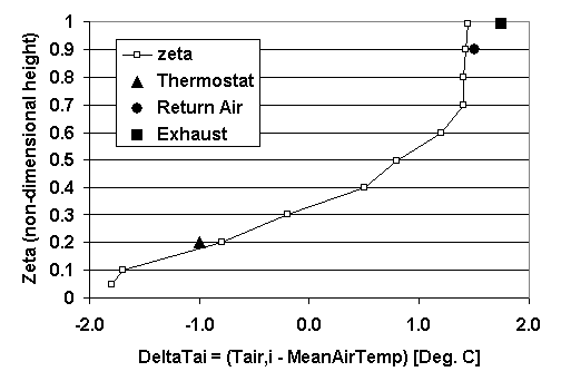
Figure 35. Example of a Vertical Air Temperature Pattern
This field provides a unique name for this object.
This field should contain an integer value that is unique among all other RoomAir Temperature Pattern objects. The value used here needs to be in the Pattern Control Schedule for those times when this pattern is to be used for the Room Air Temperature Distribution.
This field specifies the temperature difference between where the thermostat is situated and the mean air temperature.
This field specifies the temperature difference between the air leaving the zone and returning to the air system and the mean air temperature.
This field specifies the temperature difference between the air leaving the zone and being exhausted out of the building and the mean air temperature.
The remaining fields contain pairs of values that define a lookup table for the temperature pattern in the vertical direction. The first value is Zeta and the second value is DeltaTai. This object is extensible, by duplicating the last two fields and revising the IDD – note that you will have to replace “inner” semi-colons with commas.
Zeta is the normalized height and should be a fractional value from 0.0 to 1.0. A value of 0.0 corresponds to the floor and a value of 1.0 corresponds to the ceiling. The Zeta values need to be in increasing value.
DeltaTai is the temperature difference between the air temperature at the associated Zeta (Tai) and the mean air temperature and is given in degrees Celsius.
An example of this object corresponding to the figure above is:
RoomAir:TemperaturePattern:NondimensionalHeight,
Rough UFAD Approx , ! Name
3001 , ! Control Integer for Pattern Control Schedule
! note reference this entry in Schedule
-1.0 , ! Thermostat Offset
1.5 , ! Return Air Offset (Tleaving - Mean Air Temp ) deg C
1.75, ! Exhaust Air Offset (Texhaust - Mean Air Temp) deg C
0.05, -1.8, ! pair 1 (Zeta , DeltaTai)
0.1, -1.7 , ! pair 2 (Zeta , DeltaTai)
0.2, -0.8 , ! pair 3 (Zeta , DeltaTai)
0.3, -0.2, ! pair 4 (Zeta , DeltaTai)
0.4, 0.5, ! pair 5 (Zeta , DeltaTai)
0.5, 0.8, ! pair 6 (Zeta , DeltaTai)
0.6, 1.2, ! pair 7 (Zeta , DeltaTai)
0.7, 1.4, ! pair 8 (Zeta , DeltaTai)
0.8, 1.4, ! pair 9 (Zeta , DeltaTai)
0.9, 1.42, ! pair 10 (Zeta , DeltaTai)
0.95, 1.44; ! pair 11 (Zeta , DeltaTai)
This object defines a distribution pattern for the air temperatures adjacent to individual surfaces. This object uses the specific names of individual surfaces defined elsewhere in the model. This pattern allows controlling the adjacent air temperature on a surface-by-surface basis rather than by height. This allows modeling different adjacent air temperatures on the opposite sides of the zone.
In addition to the surface mappings there are three other parameters included in the pattern that are important. The first two might affect how the air system conditioning the room is operated. The first describes the temperature difference between the mean air temperature and the point where the sensor of a drybulb thermostat is situated. The second describes the temperature difference between the mean and the point where system air is being extracted from the zone. This is considered important because the changes in temperature difference between supply and return can affect how an air system is controlled to meet the loads. The third parameter can affect the zone air heat balance by altering the temperature of the air leaving the zone through exhaust fans.
This field provides a unique name for this object.
This field should contain an integer value that is unique among all other RoomAir Temperature Pattern objects. The value used here needs to be in the Pattern Control Schedule for those times when this pattern is to be used for the RoomAir Temperature Distribution.
This field specifies the temperature difference between where the thermostat is situated and the mean air temperature.
This field specifies the temperature difference between the air leaving the zone and returning to the air system and the mean air temperature.
This field specifies the temperature difference between the air leaving the zone and being exhausted out of the building and the mean air temperature.
The remaining fields contain pairs that define a lookup table for the temperature pattern on a surface-by-surface basis. This object is extensible, by duplicating the last two fields and revising the IDD – note that you will have to replace “inner” semi-colons with commas.
The name of a surface defined elsewhere in the input file.
DeltaTai is the temperature difference between the air temperature adjacent to the associated surface (Tai) and the mean air temperature and is given in degrees Celsius.
An example of this object, which might be used to elevate temperatures near west windows in the afternoon, is:
RoomAir:TemperaturePattern:SurfaceMapping,
GroundFloor SW Corner Hot Near West Wall, ! Name
4001, ! Control Integer for Pattern Control Schedule Name
0.0, ! Thermostat Offset(Temp at thermostat- Mean Air Temp)
0.0, ! Return Air Offset deg C
0.0, ! Exhaust Air Offset
ZN1_SW_1:W_ExtWall:1 , 0.8, ! pair 1 (Surface Name , DeltaTai)
ZN1_SW_1:W_ExtWall:2 , 0.9, ! pair 2 (Surface Name , DeltaTai)
ZN1_SW_1:W_ExtWall:3 , 1.0, ! pair 3 (Surface Name , DeltaTai)
ZN1_SW_1:W_ExtWall:4, 1.1, ! pair 4 (Surface Name , DeltaTai)
ZN1_SW_1:W_ExtWall:5, 1.3, ! pair 5 (Surface Name , DeltaTai)
ZN1_SW_1:W_ExtWall:6, 1.5, ! pair 6 (Surface Name , DeltaTai)
ZN1_SW_1:W_ExtWall:7, 1.7, ! pair 7 (Surface Name , DeltaTai)
ZN1_SW_1:W_ExtWall:8, 2.1, ! pair 8 (Surface Name , DeltaTai)
ZN1_SW_1:W_ExtWall:9, 2.4 ; ! pair 8 (Surface Name , DeltaTai)
The RoomAir:Node object is used to define air nodes for a nodal air model. The number of air node objects that need to be specified depends on the nodal air model selected. (However, currently only the Mundt model uses this object). In order to use the Mundt model, the user must specify six or more RoomAir:Node objects of different types for each zone. The exact number of RoomAir:Node in the model will vary based on the resolution of walls. If walls (heat transfer surfaces) are split into separate segments in the vertical direction, then more air nodes of type ‘MundtRoom’ will be useful. At a minimum, for the Mundt model RoomAir Nodes of the following type are required: ‘Inlet, ‘Floor, ‘Control, ‘Ceiling, ‘MundtRoom, and ‘Return.’
This alpha field is a name for the air node. It should be unique and is used as an identifier
This alpha field indicates the type of this air node. The following explains options available for use with the Mundt nodal air model.
Inlet is specified for the air node located where the system air enters the zone.
Floor is specified for the air node located near the floor.
Control is specified for the air node located near the thermostat.
Ceiling is specified for the air node located near the ceiling.
MundtRoom is specified for the air node located adjacent to the wall(s).
Return is specified for the air node located where the system air leaves the zone.
This field indicates the name of the zone (Ref: Zone) that this air node belongs to. This should be the unique name of a zone object defined elsewhere in the input file.
This numeric field indicates the height of the air node center. Air models such as the Mundt model compute the air temperature as a function of height and the value entered here will be used to determine a result for this node. The value should be specified in meters and relative to the floor of the zone.
These remaining alpha fields indicate the names of the surfaces (Ref: Surface) that are interacting convectively with this air node. This field is optional and related to the previous field. Currently, at most 20 surfaces are allowed to interact with a single air node. Only those nodes that interact with the inside faces of surfaces need to specify surface names. Each surface should couple to no more than 1 node.
An IDF example:
RoomAir:Node,
WESTZN:FLOORAIR, !- Node Name
Floor, !- Node Type
WEST ZONE, !- Name of Zone to Which the Air Node Belongs
0.1, !- Height of Nodal Control Volume Center {m}
WESTZN:FLOOR:LEFF, !- surface name
WESTZN:FLOOR:RIGHT; !- surface name
The RoomAirSettings:OneNodeDisplacementVentilation object is used to specify additional input parameters required by the Mundt model that are not available in other input objects in EnergyPlus. A single object will be used for the zone.
This alpha field indicates the name of the zone (Ref: Zone) for the required input parameters as specified in the following fields.
This numeric field indicates what fraction of the convective part of the internal gains is added to the air near the floor in the zone specified.
This numeric field indicates what fraction of the infiltration air enters near the floor in the zone specified.
An IDF example:
RoomAirSettings:OneNodeDisplacementVentilation,
WEST ZONE, !- Zone Name
0.1, !- Fraction of internal loads from the convective Floor Air
0.1; !- Fraction of internal loads from the Infiltration Air
This model is applicable to spaces that are served by a low velocity floor-level displacement ventilation air distribution system. Furthermore, the dominant sources of heat gain should be from people and other localized sources located in the occupied part of the room. The model should be used with caution in zones which have large heat gains or losses through exterior walls or windows or which have considerable direct solar gain. The model predicts three temperatures in the room:
· A foot level temperature (TFLOOR). The floor region is 0.2 meters deep and TFLOOR represents the temperature at the mid-point of the region.
· An occupied subzone temperature (TOC), representing the temperature in the region between the floor layer and the upper, mixed layer.
· An upper node representing the mixed-layer/outflow temperature (TMX) essential for overall energy budget calculations and for modeling comfort effects of the upper layer temperature.
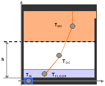
Figure 36. Schematic representation of the three temperature points and temperature gradients
The following fields are used to define an instance of the ‘UCSD Displacement Ventilation Model Controls’ object.
This field provides the unique name of a zone described elsewhere in the file. A single instance of the ‘UCSD Displacement Ventilation Model Controls’ object is needed for each zone that is to be modeled using this method.
This field specifies the unique name of schedule defined elsewhere in the input file. The schedule values are the fractions of the convective portion of the internal gains in the occupied subzone that remain in the occupied subzone. The remainder of the convective portion of the internal gains in the occupied subzone enters the plumes and is carried to the upper subzone. The types of internal gains that are assumed to be located in the occupied subzone are:
n people
n task lights
n electric equipment
n gas equipment
n hot water equipment
n steam equipment
n other equipment
n baseboard heat
Types of internal gains that are assumed to be in the upper subzone are:
n general lights
n tubular daylighting devices
n high temperature radiant heaters
The schedule values should be between 0 and 1. A value of 1 means that all the convection gains from equipment, task lights and people are dispersed in the lower occupied subzone. Conversely a value of 0 puts all the lower subzone convective gains into the plumes rising into the upper well-mixed subzone.
This field specifies number of plumes per occupant. Plumes are associated with localized sources of convective heat gain from people and equipment. For example, a value of 2.0 would be used if each occupant has a computer that generates a separate plume that does not merge with the plume from the occupant in the lower, occupied, subzone.
This field is the height in meters of the thermostat/temperature control sensor above the floor.
The height in meters above the floor at which air temperature is calculated for comfort purposes. The air temperature at this height is used in calculating the available measures of comfort: Fanger, Pierce or KSU. The default is 1.1 meters.
This field specifies a minimum temperature difference between the upper mixed subzone and the occupied subzone that will be used to trigger whether or not the displacement ventilation auxiliary outputs will be calculated. These outputs are DV Transition Height, DV Fraction Min Recommended Flow Rate, DV Average Temp Gradient and DV Maximum Temp Gradient. They are set to negative values when the temperature difference is less than the threshold and the output DV Zone Is Mixed is set to 1.
The value should be greater than or equal to zero and is in units of degrees Centigrade. The default value is 0.4 degrees C.
An example input:
RoomAirSettings:ThreeNodeDisplacementVentilation,
ZONE ONE, !- Zone Name
Constant - .2, !- Gain Distribution Schedule Name
1, !- Number of Plumes per Occupant
, !- Thermostat Height
, !- Comfort Height
.3; !- Temp. Difference Threshold for Displacement Ventilation
This UCSD Cross Ventilation Room Air Model provides a simple model for heat transfer and vertical temperature profile prediction in cross ventilated rooms. The model distinguishes two regions in the room, the main jet region and the recirculations, and predicts characteristic airflow velocities and average air temperatures. Cross Ventilation (CV) is common in many naturally ventilated buildings, with air flowing through windows, open doorways and large internal apertures across rooms and corridors in the building.
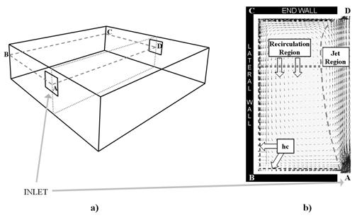
Figure 37. Schematic representation of room air geometry a) schematic representation of a room geometry that generates cross ventilation airflow. b) the proposed model distinguishes two regions in the flow: jet and recirculation (shown here in a CFD simulation of one half of a symmetrical room).
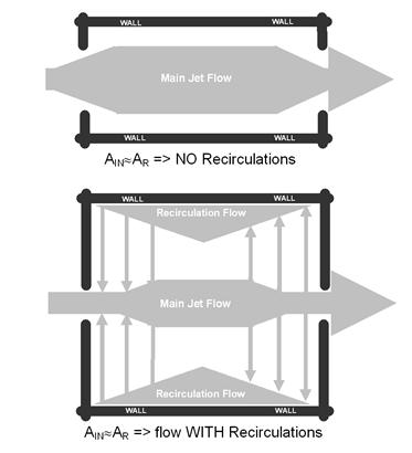
Figure 38. Schematic top view –possible airflow patterns in cross-ventilation.
The following fields are used to define an instance of the ‘UCSD Cross Ventilation Model Controls’ object.
This field provides the unique name of a zone described elsewhere in the file. A single instance of the ‘UCSD Cross Ventilation Model Controls’ object is needed for each zone that is to be modeled using this method.
This field specifies the unique name of schedule defined elsewhere in the input file. The schedule values are the fractions of the convective portion of the internal gains in the jet and recirculation regions.
The schedule values should be between 0 and 1. A value of 1 means that all the convective gains are dispersed in the jet region. Conversely a value of 0 puts all the convective gains into the recirculation region.
Required field whenever thermal comfort is predicted defines air temperature and mean airflow velocity that will be used in the Fanger model conditions must refer to one of the two regions defined in the model: jet or recirculation. Possible choices: Jet or Recirculation.
An example input:
RoomAirSettings:CrossVentilation,
ZONE ONE, !- Zone Name
Constant - .2, !- Gain Distribution Schedule
Recirculation; !- Region used for thermal comfort evaluation
This model is applicable to interior spaces that are served by an underfloor air distribution system. The dominant sources of heat gain should be from people, equipment, and other localized sources located in the occupied part of the room. The model should be used with caution in zones which have large heat gains or losses through exterior walls or windows or which have considerable direct solar gain. The model predicts two temperatures in the room:
n An occupied subzone temperature (TOC), representing the temperature in the region between the floor and the boundary of the upper subzone..
n An upper subzone temperature (TMX) essential for overall energy budget calculations and for modeling comfort effects of the upper layer temperature.
The following fields are used to define an instance of the ‘UCSD UFAD Interior Model Controls’ object.
This field provides the unique name of a zone described elsewhere in the file. A single instance of the ‘RoomAirSettings:UnderFloorAirDistributionInterior’ object is needed for each zone that is to be modeled using this method.
This is the design air flow opening area in square meters of a single diffuser. The default value depends on the diffuser type. For swirl diffusers it is 0075 m2, for variable area diffusers 0.035 m2, for horizontal swirl diffusers 0.006 m2, and for linear bar grilles 0.03 m2. The default is Autocalculate..
This input describes the angle at which air emerges from the diffusers. It should be the angle in degrees between the vertical and the diffuser slots. The defaults depend on the diffuser type: for swirl diffusers it is 28 degrees, for variable area diffusers 45 degrees, for DV diffusers 73 degrees, and for linear bar grilles 15 degrees.
This field is the height in meters of the thermostat/temperature control sensor above the floor. The default is 1.2 meters.
The height in meters above the floor at which air temperature is calculated for comfort purposes. The air temperature at this height is used in calculating the available measures of comfort: Fanger, Pierce or KSU. The default is 1.1 meters.
This field specifies a minimum temperature difference between the upper subzone and the occupied subzone that will be used to trigger whether or not the UFAD auxiliary outputs will be calculated. These outputs are UF Transition Height and UF Average Temp Gradient. They are set to zero when the temperature difference is less than the threshold and the output UF Zone Is Mixed is set to 1.
The value should be greater than or equal to zero and is in units of degrees Centigrade. The default value is 0.4 degrees C.
The choices for this alpha field are Swirl | VariableArea | HorizontalSwirl | LinearBarGrille | Custom. The swirl and displacement diffusers are fixed area diffusers. The variable area diffusers maintain an approximately constant exit velocity. Linear bar grilles are normally used in exterior zonesand are fixed area diffusers. Custom is used to signify that the user intends to input the coefficients A – E (see below) rather than let the program set the coefficients based on diffuser type. The default is Swirl.
An optional field to allow the user to specify the transition height (meters above floor) rather than have the program calculate it. The default is 1.7 meters.
The coefficient A in the formula: Kc = A*Gamma**B + C + D*Gamma + E*Gamma**2. Gamma is a variable that characterizes the amount of stratification in a UFAD zone. Kc is the fraction of the total internal convective heat gain that is assigned to the lower (occupied) subzone. The coefficients in the formula are defaulted based upon diffuser type. A user would normally allow this field to default. The default is autocalulate.
The coefficient B in the formula: Kc = A*Gamma**B + C + D*Gamma + E*Gamma**2. Gamma is a variable that characterizes the amount of stratification in a UFAD zone. Kc is the fraction of the total internal convective heat gain that is assigned to the lower (occupied) subzone. The coefficients in the formula are defaulted based upon diffuser type. A user would normally allow this field to default. The default is autocalulate.
The coefficient C in the formula: Kc = A*Gamma**B + C + D*Gamma + E*Gamma**2. Gamma is a variable that characterizes the amount of stratification in a UFAD zone. Kc is the fraction of the total internal convective heat gain that is assigned to the lower (occupied) subzone. The coefficients in the formula are defaulted based upon diffuser type. A user would normally allow this field to default. The default is autocalulate.
The coefficient D in the formula: Kc = A*Gamma**B + C + D*Gamma + E*Gamma**2. Gamma is a variable that characterizes the amount of stratification in a UFAD zone. Kc is the fraction of the total internal convective heat gain that is assigned to the lower (occupied) subzone. The coefficients in the formula are defaulted based upon diffuser type. A user would normally allow this field to default. The default is autocalulate.
The coefficient E in the formula: Kc = A*Gamma**B + C + D*Gamma + E*Gamma**2. Gamma is a variable that characterizes the amount of stratification in a UFAD zone. Kc is the fraction of the total internal convective heat gain that is assigned to the lower (occupied) subzone. The coefficients in the formula are defaulted based upon diffuser type. A user would normally allow this field to default. The default is autocalulate.
An example input is:
RoomAirModelType,
SPACE5-1 RoomAir Model, !- Name
SPACE5-1, !- Zone Name
UnderFloorAirDistributionInterior, !- Room-Air Modeling Type
DIRECT; !- Air Temperature Coupling Strategy
RoomAirSettings:UnderFloorAirDistributionInterior,
SPACE5-1, !- Zone Name
Autocalculate, !- Number of Diffusers
Autocalculate, !- Power per Plume
Autocalculate, !- Design Effective Area of Diffuser {m2}
Autocalculate, !- Diffuser Slot Angle from Vertical {deg}
, !- Thermostat Height {m}
, !- Comfort Height {m}
0.001, !- Temperature Difference Threshold for Reporting {deltaC}
Swirl, !- Diffuser Type
1.7, !- Transition Height {m}
Autocalculate, !- Coefficient A
Autocalculate, !- Coefficient B
Autocalculate, !- Coefficient C
Autocalculate, !- Coefficient D
Autocalculate; !- Coefficient E
This model is applicable to exterior spaces that are served by an underfloor air distribution system. The dominant sources of heat gain should be from people, equipment, and other localized sources located in the occupied part of the room, as well as convective gain coming from a warm window. The model predicts two temperatures in the room:
n An occupied subzone temperature (TOC), representing the temperature in the region between the floor and the boundary of the upper subzone..
n An upper subzone temperature (TMX) essential for overall energy budget calculations and for modeling comfort effects of the upper layer temperature.
The following fields are used to define an instance of the ‘UCSD UFAD Exterior Model Controls’ object.
This field provides the unique name of a zone described elsewhere in the file. A single instance of the ‘RoomAirSettings:UnderFloorAirDistributionExterior’ object is needed for each zone that is to be modeled using this method.
This is the design air flow opening area in square meters of a single diffuser. The default value depends on the diffuser type. For swirl diffusers it is 0075 m2, for variable area diffusers 0.035 m2, for horizontal swirl diffusers 0.006 m2, and for linear bar grilles 0.03 m2. The default is Autocalculate..
This input describes the angle at which air emerges from the diffusers. It should be the angle in degrees between the vertical and the diffuser slots. The defaults depend on the diffuser type: for swirl diffusers it is 28 degrees, for variable area diffusers 45 degrees, for DV diffusers 73 degrees, and for linear bar grilles 15 degrees.
This field is the height in meters of the thermostat/temperature control sensor above the floor. The default is 1.2 meters.
The height in meters above the floor at which air temperature is calculated for comfort purposes. The air temperature at this height is used in calculating the available measures of comfort: Fanger, Pierce or KSU. The default is 1.1 meters.
This field specifies a minimum temperature difference between the upper subzone and the occupied subzone that will be used to trigger whether or not the UFAD auxiliary outputs will be calculated. These outputs are UF Transition Height and UF Average Temp Gradient. They are set to zero when the temperature difference is less than the threshold and the output UF Zone Is Mixed is set to 1.
The value should be greater than or equal to zero and is in units of degrees Centigrade. The default value is 0.4 degrees C.
The choices for this alpha field are Swirl | VariableArea | HorizontalSwirl | LinearBarGrille | Custom. The swirl and displacement diffusers are fixed area diffusers. The variable area diffusers maintain an approximately constant exit velocity. Linear bar grilles are normally used in exterior zonesand are fixed area diffusers. Custom is used to signify that the user intends to input the coefficients A – E (see below) rather than let the program set the coefficients based on diffuser type. The default is Swirl.
An optional field to allow the user to specify the transition height (meters above floor) rather than have the program calculate it. The default is 1.7 meters.
The coefficient A in the formula: Kc = A*Gamma**B + C + D*Gamma + E*Gamma**2. Gamma is a variable that characterizes the amount of stratification in a UFAD zone. Kc is the fraction of the total internal convective heat gain that is assigned to the lower (occupied) subzone. The coefficients in the formula are defaulted based upon diffuser type. A user would normally allow this field to default. The default is autocalulate.
The coefficient B in the formula: Kc = A*Gamma**B + C + D*Gamma + E*Gamma**2. Gamma is a variable that characterizes the amount of stratification in a UFAD zone. Kc is the fraction of the total internal convective heat gain that is assigned to the lower (occupied) subzone. The coefficients in the formula are defaulted based upon diffuser type. A user would normally allow this field to default. The default is autocalulate.
The coefficient C in the formula: Kc = A*Gamma**B + C + D*Gamma + E*Gamma**2. Gamma is a variable that characterizes the amount of stratification in a UFAD zone. Kc is the fraction of the total internal convective heat gain that is assigned to the lower (occupied) subzone. The coefficients in the formula are defaulted based upon diffuser type. A user would normally allow this field to default. The default is autocalulate.
The coefficient D in the formula: Kc = A*Gamma**B + C + D*Gamma + E*Gamma**2. Gamma is a variable that characterizes the amount of stratification in a UFAD zone. Kc is the fraction of the total internal convective heat gain that is assigned to the lower (occupied) subzone. The coefficients in the formula are defaulted based upon diffuser type. A user would normally allow this field to default. The default is autocalulate.
The coefficient E in the formula: Kc = A*Gamma**B + C + D*Gamma + E*Gamma**2. Gamma is a variable that characterizes the amount of stratification in a UFAD zone. Kc is the fraction of the total internal convective heat gain that is assigned to the lower (occupied) subzone. The coefficients in the formula are defaulted based upon diffuser type. A user would normally allow this field to default. The default is autocalulate.
An example input is:
RoomAirSettings:UnderFloorAirDistributionExterior,
SPACE1-1, !- Zone Name
Autocalculate, !- Number of Diffusers per Zone
Autocalculate, !- Power per Plume
Autocalculate, !- Design Effective Area of Diffuser {m2}
Autocalculate, !- Diffuser Slot Angle from Vertical {deg}
, !- Thermostat Height {m}
, !- Comfort Height {m}
0.001, !- Temperature Difference Threshold for Reporting {deltaC}
LinearBarGrille, !- Diffuser Type
1.7, !- Transition Height {m}
Autocalculate, !- Coefficient A
Autocalculate, !- Coefficient B
Autocalculate, !- Coefficient C
Autocalculate, !- Coefficient D
Autocalculate; !- Coefficient E
Each room air model sets up outputs specific to that model. The effect of room air modeling is usually to adjust the adjacent air temperature along the inside surface of heat transfer surfaces. The output report “Surface Int Adjacent Air Temperature [C]” is provided for this and described under Surface Outputs.
The user-defined air temperature pattern that interpolates between two gradients produces the following output variable.
This output variable is the result of the interpolation performed by the user-defined roomair model using RoomAir:TemperaturePattern:TwoGradient. This is the temperature gradient in the vertical direction. The units are degrees Centigrade per meter.
The following output is available for the Mundt model.
Mundt RoomAir Model Air Node Temp [C]
This report variable provides the drybulb air temperature used in, or calculated by, the Mundt model. The selection key is the name of an air node defined in a ROOMAIR Node object.
HVAC,Average,DV Mixed Subzone Temperature[C]
HVAC,Average,DV Occupied Subzone Temperature[C]
HVAC,Average,DV Floor Subzone Temperature[C]
HVAC,Average,DV Transition Height [m]
HVAC,Average,DV Fraction Min Recommended Flow Rate
HVAC,Average,DV Zone Is Mixed [0-No 1-Yes]
HVAC,Average,DV Average Temp Gradient [K/m]
HVAC,Average,DV Maximum Temp Gradient [K/m]
HVAC,Average,DV Effective Air Temperature for Comfort [C]
HVAC,Average,DV Thermostat Temperature [C]
The temperature of the upper well-mixed subzone in degrees C.
The average temperature of the lower, stratified, occupied subzone in degrees C.
The temperature of the region near the floor in degrees C.
The height above the floor, in meters, of the boundary between the lower occupied subzone and the upper well-mixed subzone.
The ratio of the minimum recommended flow rate to the actual flow rate. Here flow rate means the sum of infiltration, ventilation, mixing and system air flow rates. The minimum flow is the flow needed to establish the boundary between the occupied and mixed subzones at 1.5 meters.
An integer flag that indicates whether the zone is mixed (single node well-mixed zone model used) or stratified (UCSD DV model used). The value 1 means well-mixed; 0 means stratified.
The temperature gradient between the middle of the floor region and the middle of the well-mixed upper subzone in degrees Kelvin per meter.
The maximum of the temperature gradient between the middle of the floor region and the middle of the occupied subzone and the temperature gradient between the middle of the occupied subzone and the middle of the well-mixed subzone. The gradient is in degrees Kelvin per meter.
The temperature at the user specified comfort height in degrees C.
The temperature at the height of the thermostat (specified by user input) in degrees C.
Zone,Average,CV Jet Region Temperature[C]
Zone,Average,CV Recirculation Region Temperature[C]
Zone,Average,CV Jet Region Average Velocity[m/s]
Zone,Average,CV Recirculation Region Average Velocity[m/s]
Zone,Average,CV Inflow Aperture Area[m2]
Zone,Average,CV Room Length[m]
Zone,Average,CV Ratio Between Recirculation and Inflow Rate
Zone,Average,CV Zone Air is Mixing [1-Yes 0-No]
Zone,Average,CV Recirculations Occur In The Flow [1-Yes 0-No]
Average air temperature in the jet region of the flow in degrees C.
Average air temperature in the recirculation region of the flow in degrees C.
Average airflow velocity in the jet region of the flow in meters per second.
Average airflow velocity in the recirculation region of the flow in meters per second.
Area of the inflow aperture in square meters. This area can change due to variation in wind direction (as inflow aperture changes) or variations in the opening schedule.
Length of the room along the cross ventilation direction, in meters.
Ratio between airflow rate in the recirculation region and inflow rate, non-dimensional.
An integer flag that indicates whether the zone is mixed (single node well-mixed zone model used) or significant momentum conservation is occurring (UCSD CV model used). The value 1 means well-mixed; 0 means cross ventilation is present. Transition to mixed flow can occur due to three mechanism: reduction in inflow velocity, reduction in inflow aperture area and dominance of buoyancy effects.
An integer flag that indicates whether recirculations are present in the flow. A cross ventilation flow does not have recirculations whenever the inflow area is similar to the room cross section area (such as airflow in a typical corridor).
HVAC,Average,UF Mixed Subzone Temperature [C]
HVAC,Average,UF Occupied Subzone Temperature [C]
HVAC,Average,UF Transition Height [m]
HVAC,Average,UF Zone Is Mixed [0-No 1-Yes]
HVAC,Average,UF Average Temp Gradient [K/m]
HVAC,Average,UF Effective Air Temperature for Comfort [C]
HVAC,Average,UF Thermostat Temperature [C]
HVAC,Average,UF Gamma
HVAC,Average,UF Power In Plumes [W]
HVAC,Average,Phi
HVAC,Average,UF Plume Power from Windows [W]UCSD Supply Air Temp
HVAC,Average,Phi
The temperature of the upper subzone in degrees C.
The temperature of the lower, occupied subzone in degrees C.
The height above the floor, in meters, of the boundary between the lower occupied subzone and the upper subzone..
An integer flag that indicates whether the zone is mixed (single node well-mixed zone model used) or stratified (UCSD UFI model used). The value 1 means well-mixed; 0 means stratified.
The temperature gradient between the middle of the occupied subzone and the middle of the upper subzone in degrees Kelvin per meter.
The temperature at the user specified comfort height in degrees C.
The temperature at the height of the thermostat (specified by user input) in degrees C.
Value of gamma – a dimensionless “height” used in calculating the transition height. Lower values of gamma indicate increased stratification, higher values less. Generally the values should be between 2 and 30.
The heat in watts driving the plumes in the occupied subzone.
The convective heat gain from windows in an UnderFloorAirDistributionExterior zone.
Phi is a measure of temperature stratification in the space. It is the difference between the occupied subzone temperature and the supply temperature divided by difference between the return temperature and the supply temperature. Technically it is equal to Kc. As phi approaches 1, the space is fully mixed. As phi approaches 0, the space becomes fully stratified. Expressed as an equation:
(Tocc – Tsup) / (Tret - Tsup)
Not all the influence for energy consumption in the building is due to envelope and ambient conditions. This group of objects describes other internal gains that may come into play (People, Lights, Various Equipment Types).
The people statement is used to model the occupant’s affect on the space conditions. The following definition addresses the basic affects as well as providing information that can be used to report the thermal comfort of a group of occupants. The Fanger, Pierce Two-Node, and Kansas State University Two-Node thermal comfort models are available in EnergyPlus. A user may select any of these models for each People statement by simply adding the appropriate choice keyword after the air velocity schedule name. Thermal comfort calculations will only be made for people statements that include specific requests for these thermal comfort models. . This object also requires input of carbon dioxide generation rate based on people activity level for zone carbon dioxide simulations.
The name of the People object. Must be unique across all People objects.
This field is the name of the zone (ref: Zone) or ZoneList (ref: ZoneList) and links a particular people statement to a thermal zone or set of thermal zones in the building. When the ZoneList option is used then this people definition is applied to each of the zones in the zone list effecting a global definition for the number of people in the zone. This option can be used effectively with the people/area and area/person options of the Number of People Calculation Method.
This field is the name of the schedule (ref: Group -- Schedules) that modifies the number of people parameter (see previous field). The schedule values can be any positive number. The actual number of people in a zone as defined by this statement is the product of the number of people field and the value of the schedule specified by name in this field.
This field is a key/choice field that tells which of the next three fields are filled and is descriptive of the method for calculating the nominal number of occupants (people) in the Zone. The key/choices are:
n People
With this choice, the method used will be a straight insertion of the number of occupants (people). (The Number of People field should be filled.)
n People/Area
With this choice, the method used will be a factor per floor area of the zone. (The People per Zone Floor Area field should be filled).
n Area/Person
With this choice, the method used will be a factor of floor area per person. (The Zone Floor Area per Person field should be filled).
This field is used to represent the maximum number of people in a zone that is then multiplied by a schedule fraction (see schedule field). In EnergyPlus, this is slightly more flexible in that the number of people could be a “diversity factor” applied to a schedule of real numbers. Note that while the schedule value can vary from hour to hour, the number of people field is constant for all simulation environments.
This factor (person/m2) is used, along with the Zone Floor Area to determine the maximum number of people as described in the Number of People field. The choice from the method field should be “people/area”.
This factor (m2/person) is used, along with the Zone Floor Area to determine the maximum number of people as described in the Number of People field. The choice from the method field should be “area/person”.
This field is a decimal number between 0.0 and 1.0 and is used to characterize the type of heat being given off by people in a zone. The number specified in this field will be multiplied by the total sensible energy emitted by people to give the amount of long wavelength radiation gain from human beings in a zone. The remainder of the sensible load is assumed to be convective heat gain. Note that latent gains from people are not included in either the radiant or convective heat gains. See the Engineering Reference document for more details.
The user can use this field to specify a fixed sensible fraction for the heat gain due to this PEOPLE object. Normally the program calculates the sensible/latent split; this field gives the user control over this split. This field is autocalculated: if the field is blank or autocalculate, the program will calculate the sensible/latent split; if a value is entered, it will be used as the sensible fraction of the current total heat gain.
This field is the name of the schedule that determines the amount of heat gain per person in the zone under design conditions. This value is modified somewhat based on a correlation to account for variations in space temperature. The schedule values may be any positive number and the units for this parameter is Watts per person. This schedule represents the total heat gain per person including convective, radiant, and latent. An internal algorithm is used to determine what fraction of the total is sensible and what fraction is latent. Then, the sensible portion is divided into radiant and convective portions using the value specified for Fraction Radiant (above). See the Engineering Reference document for more details.
Values for activity level can range anywhere from approximately 100-150 Watts per person for most office activities up to over 900 Watts per person for strenuous physical activities such as competitive wrestling. The following table (Table 11) is based on Table 4 from the 2005 ASHRAE Handbook of Fundamentals, page 8.6. In addition to the information from the ASHRAE HOF, there is an added column of values in W/Person such as necessary for the activity level schedule values. This column uses the standard adult body surface area of 1.8 m2 to multiply the activity levels in W/m2 that are used in the table. Warnings are produced when the activity level schedule values fall outside normal ranges. Having too low or too high values can also skew thermal comfort reporting values.
This numeric input field specifies carbon dioxide generation rate per person with units of m3/s-W. The total carbon dioxide generation rate from this object is:
Number of People * People Schedule * People Activity * Carbon Dioxide Generation Rate. The default value is 3.82E-8 m3/s-W (obtained from ASHRAE Standard 62.1-2007 value at 0.0084 cfm/met/person over the general adult population). The maximum value can be 10 times the default value.
This field accepts either “Yes” or “No” as values. When “Yes” is specified, warnings are generated when the space conditions are outside of the ASHRAE 55 comfort range as discussed in the sections that follow titled “Simplified ASHRAE 55-2004 Graph Related Outputs” and “Simplified ASHRAE 55 Warnings.” The default is not to provide these warnings so if you want to know if your space is outside this comfort range you must set this field to Yes.
Table 11. Metabolic Rates for Various Activities
|
Activity |
Activity Level W/Person EnergyPlus Schedule Value |
Activity Level W/m2 |
met* |
|
Resting |
|||
|
Sleeping |
72 |
40 |
0.7 |
|
Reclining |
81 |
45 |
0.8 |
|
Seated, quiet |
108 |
60 |
1 |
|
Standing, relaxed |
126 |
70 |
1.2 |
|
Walking (on level surface) |
|||
|
3.2 km/h (0.9 m/s) |
207 |
115 |
2 |
|
4.3 km/h (1.2 m/s) |
270 |
150 |
2.6 |
|
6.4 km/h (1.8 m/s) |
396 |
220 |
3.8 |
|
Office Activities |
|||
|
Reading, seated |
99 |
55 |
1 |
|
Writing |
108 |
60 |
1 |
|
Typing |
117 |
65 |
1.1 |
|
Filing, seated |
126 |
70 |
1.2 |
|
Filing, standing |
144 |
80 |
1.4 |
|
Walking about |
180 |
100 |
1.7 |
|
Lifting/packing |
216 |
120 |
2.1 |
|
Miscellaneous Occupational Activities |
|||
|
Cooking |
171 to 207 |
95 to 115 |
1.6 to 2.0 |
|
Housecleaning |
207 to 360 |
115 to 200 |
2.0 to 3.4 |
|
Seated, heavy limb movement |
234 |
130 |
2.2 |
|
Machine work |
|
|
|
|
sawing (table saw) |
189 |
105 |
1.8 |
|
light (electrical industry) |
207 to 252 |
115 to 140 |
2.0 to 2.4 |
|
heavy |
423 |
235 |
4 |
|
Handling 50 kg bags |
423 |
235 |
4 |
|
Pick and shovel work |
423 to 504 |
235 to 280 |
4.0 to 4.8 |
|
Miscellaneous Leisure Activities |
|||
|
Dancing, social |
252 to 459 |
140 to 255 |
2.4 to 4.4 |
|
Calisthenics/exercise |
315 to 423 |
175 to 235 |
3.0 to 4.0 |
|
Tennis, singles |
378 to 486 |
210 to 270 |
3.6 to 4.0 |
|
Basketball |
522 to 792 |
290 to 440 |
5.0 to 7.6 |
|
Wrestling, competitive |
738 to 909 |
410 to 505 |
7.0 to 8.7 |
*Note that one met = 58.1 W/m2
This field specifies the type of Mean Radiant Temperature (MRT) calculation the user wishes to use for the thermal comfort model. At the present time, there are two options for MRT calculation type: zone averaged and surface weighted. The default calculation is “ZoneAveraged”. In the zone averaged MRT calculation, the MRT used for the thermal comfort calculations is for an “average” point in the zone. MRT is calculated based on an area-emissivity weighted average of all of the surfaces in the zone. In cases where the emissivity of all of the surfaces are sufficiently small (near zero), the mean radiant temperature will be set to the mean air temperature of the space to avoid divide by zero errors. The other MRT calculation type is “SurfaceWeighted”. The goal of this calculation type is to estimate a person in the space close to a particular surface without having to define exact view factors for all of the surfaces and the location of the person in the space. The MRT used in the thermal comfort calculations when the “surface weighted” calculation type is selected is actually the average of the temperature of the surface to which the person is closest (defined by the next field “Surface Name”) and the zone averaged MRT (defined above). The surface temperature alone is not used because in theory the maximum view factor from a person to any flat surface is roughly 0.5. In the “surfaceweighted” calculation, the surface in question actually gets slightly more weighting than 50% since the surface selected is still a part of the zone average MRT calculation. Again, this simplification was made to avoid the specification of view factors and the exact location of the person.
A third option is to use “anglefactor”. This option allows for more explicit positioning of the person within the space by defining the angle factors from the person to the various surfaces in the zone. This option requires the user to list the surfaces that the person can see from a radiation standpoint and also define the angle (or view) factor for each surface. The AngleFactorList object (see next object description) is intended to give the user this opportunity.
This field is only valid when the user selects “surfaceweighted” for the MRT calculation type (see the previous input field description). In this case, the field is the name of a surface within the zone the people are residing. This surface will be used in the MRT calculation as defined above to come up with a more representative MRT for a person near a particular surface. The MRT used for thermal comfort calculations using the “surface weighted” MRT calculation method is the average of the temperature of the surface specified in this field and the “zone averaged” MRT (see the Mean Radiant Temperature calculation type field above).
This field is the name of the schedule that determines the efficiency of energy usage within the human body that will be used for thermal comfort calculations. Note that all energy produced by the body is assumed to be converted to heat for the zone heat balance calculation. A value of zero corresponds to all of the energy produced in the body being converted to heat. A value of unity corresponds to all of the energy produced in the body being converted to mechanical energy. The values for this parameter defined in the schedule must be between 0.0 and 1.0. Any value greater than zero will result in a reduction of heat that impacts the thermal comfort energy balance of a person within the space.
This field is the name of the schedule that defines the amount of clothing being worn by a typical zone occupant during various times in the simulation period. This parameter must be a positive real number and has units of Clo. Typical values for Clo can be seen in the ASHRAE 2009 HOF Table 7, page 9.8 (for clothing ensembles) and Table 8, page 9.9 (for garment values).
This field is the name of the schedule that approximates the amount of air movement in the space as a function of time throughout the simulation period. The user has control over this parameter through the schedule that requires the individual numbers in the schedule to be positive real numbers having units of meters per second.
The final one to five fields are optional and are intended to trigger various thermal comfort models within EnergyPlus. By entering the keywords Fanger, Pierce, KSU, ASHRAE55AdaptiveComfort, and CEN15251AdaptiveComfort, the user can request the Fanger, Pierce Two-Node, Kansas State UniversityTwo-Node, and the adaptive comfort models of the ASHRAE Standard 55 and CEN Standard 15251 results for this particular people statement. Note that since up to five models may be specified, the user may opt to have EnergyPlus calculate the thermal comfort for people identified with this people statement using all five models if desired. Note that the KSU model is computationally intensive and may noticeably increase the execution time of the simulation. For descriptions of the thermal comfort calculations, see the Engineering Reference document.
The following IDF example allows for a maximum of 31 people with scheduled occupancy of “Office Occupancy”, 60% radiant using an Activity Schedule of “Activity Sch”. The example allows for thermal comfort reporting.
People,
Kitchen_ZN_1_FLR_1, !- Name
Kitchen_ZN_1_FLR_1, !- Zone or ZoneList Name
BLDG_OCC_SCH, !- Number of People Schedule Name
People, !- Number of People Calculation Method
25.2000,,, !- Number of People, People per Zone Floor Area, Zone Floor Area per Person
0.3000, !- Fraction Radiant
AUTOCALCULATE, !- Sensible Heat Fraction
ACTIVITY_SCH, !- Activity Level Schedule Name
3.82E-8 !- Carbon Dioxide Generation Rate {m3/s-W}
No, !- Enable ASHRAE 55 Comfort Warnings
ZoneAveraged, !- Mean Radiant Temperature Calculation Type
, !- Surface Name/Angle Factor List Name
WORK_EFF_SCH, !- Work Efficiency Schedule Name
CLOTHING_SCH, !- Clothing Insulation Schedule Name
AIR_VELO_SCH, !- Air Velocity Schedule Name
Fanger; !- Thermal Comfort Model 1 Type
A simpler example, without using the thermal comfort reporting option:
People,
RIGHT FORK, !- Name
RIGHT FORK, !- Zone or ZoneList Name
Dorm Occupancy, !- Number of People Schedule Name
people, !- Number of People Calculation Method
8.00000, !- Number of People,
, !- People per Zone Floor Area
, !- Zone Floor Area per Person
0.6000000, !- Fraction Radiant
Autocalculate, !- Sensible Heat Fraction
Activity Sch, !- Activity level Schedule Name
And with the sensible fraction specified:
People,
SPACE1-1 People 1, !- Name
SPACE1-1, !- Zone or ZoneList Name
OCCUPY-1, !- Number of People Schedule Name
people, !- Number of People Calculation Method
11, !- Number of People
, !- People per Zone Floor Area
, !- Zone Floor Area per Person
0.3, !- Fraction Radiant
0.55, !- Sensible Heat Fraction
ActSchd; !- Activity level Schedule Name
Global People Object:
ZoneList,AllOccupiedZones,SPACE1-1,SPACE2-1,SPACE3-1,SPACE4-1,SPACE5-1;
People,
AllZones with People, !- Name
AllOccupiedZones, !- Zone or ZoneList Name
OCCUPY-1, !- Number of People Schedule Name
People/Area, !- Number of People Calculation Method
, !- Number of People
.11, !- People per Zone Floor Area {person/m2}
, !- Zone Floor Area per Person {m2/person}
0.3, !- Fraction Radiant
, !- Sensible Heat Fraction
ActSchd; !- Activity Level Schedule Name
People objects have output variables for individual objects and for zone totals.
People specific outputs include:
Zone,Average,People Number Of Occupants []
Zone,Sum,People Radiant Heat Gain [J]
Zone,Average,People Radiant Heat Gain Rate [W]
Zone,Sum,People Convective Heat Gain [J]
Zone,Average,People Convective Heat Gain Rate [W]
Zone,Sum,People Sensible Heat Gain [J]
Zone,Average,People Sensible Heat Gain Rate [W]
Zone,Sum,People Latent Heat Gain [J]
Zone,Average,People Latent Heat Gain Rate [W]
Zone,Sum,People Total Heat Gain [J]
Zone,Average,People Total Heat Gain Rate [W]
Zone,Average,Zone People Number Of Occupants []
Zone,Sum,Zone People Radiant Heat Gain [J]
Zone,Average,Zone People Radiant Heat Gain Rate [W]
Zone,Sum,Zone People Convective Heat Gain [J]
Zone,Average,Zone People Convective Heat Gain Rate [W]
Zone,Sum,Zone People Sensible Heat Gain [J]
Zone,Average,Zone People Sensible Heat Gain Rate [W]
Zone,Sum,Zone People Latent Heat Gain [J]
Zone,Average,Zone People Latent Heat Gain Rate [W]
Zone,Sum,Zone People Total Heat Gain [J]
Zone,Average,People Air Temperatures [C]
Zone,Average,People Air Relative Humidity [%]
Zone,Average,Zone People Total Heat Gain Rate [W]
Zone,Average,ThermalComfortMRT [C]
Zone,Average,ThermalComfort Operative Temperature [C]
Zone,Average,FangerPMV []
Zone,Average,FangerPPD []
Zone,Average,Clothing Surface Temperature [C]
Zone,Average,PiercePMVET []
Zone,Average,PiercePMVSET []
Zone,Average,PierceDISC []
Zone,Average,PierceTSENS []
Zone,Average,KsuTSV []
Zone,Average,ASHRAE55AdaptiveComfort at 80% Acceptability Limits [] Zone,Average,ASHRAE55AdaptiveComfort at 90% Acceptability Limits []
Zone,Average,ASHRAE55 Running Mean Outdoor Temperature [C]
Zone,Average,ASHRAE55 Adaptive Comfort Temperature [C]
Zone,Average,CEN15251AdaptiveComfort at Category I []
Zone,Average,CEN15251AdaptiveComfort at Category II []
Zone,Average,CEN15251AdaptiveComfort at Category III
Zone,Average,CEN15251 Running Mean Outdoor Temperature [C]
Zone,Average,CEN15251 Adaptive Comfort Temperature [C]
This field is the number of people for this PEOPLE object during the timestep in question.
These report variables are the amount of radiant heat gain for this People object in Watts (for rate) or Joules. This is determined by the current sensible heat gain from people to the zone and the “Fraction Radiant” specified in the input. The radiant gains from people are distributed to the surfaces using an area weighting scheme.
These report variables are the amount of convective heat gain for this People object in Watts (for rate) or Joules. This is determined by the current sensible heat gain from people to the zone and the “Fraction Radiant” specified in input. Note that the radiant and convective gains should add up to the sensible heat gain from people. The convective heat gain from people is added to the zone air heat balance directly.
These report variables are the amount of latent heat gain for this People object in Watts (for rate) or Joules. This amount is based on the number of people in the space as well as the total amount of energy produced by a typical person defined by the activity schedule in the input. An internal algorithm is used to determine what fraction of the total is sensible and what fraction is latent. Details about this split are included in the Engineering Reference document.
These report variables are the amount of sensible heat gain for this People object in Watts (for rate) or Joules. This amount is based on the number of people in the space as well as the total amount of energy produced by a typical person defined by the activity schedule in the input. An internal algorithm (described in the Engineering Reference document) is used to determine what fraction of the total is sensible and what fraction is latent. The sensible plus the latent heat gain from people equals the total gain specified in the input.
These report variables are the total amount of heat gain for this People object in Watts (for rate) or Joules. This is derived from the activity level times the number of occupants.
At writing of this document, trying to determine what this is.
At writing of this document, trying to determine what this is.
This field is the total number of people within the zone during the timestep in question.
These report variables are the amount of radiant heat gain from people within the zone in Watts (for rate) or Joules. This is determined by the current sensible heat gain from people to the zone and the “Fraction Radiant” specified in the input. The radiant gains from people are distributed to the surfaces using an area weighting scheme.
These report variables are the amount of convective heat gain from people within the zone in Watts (for rate) or Joules. This is determined by the current sensible heat gain from people to the zone and the “Fraction Radiant” specified in input. Note that the radiant and convective gains should add up to the sensible heat gain from people. The convective heat gain from people is added to the zone air heat balance directly.
These report variables are the amount of latent heat gain from people within the zone in Watts (for rate) or Joules. This amount is based on the number of people in the space as well as the total amount of energy produced by a typical person defined by the activity schedule in the input. An internal algorithm is used to determine what fraction of the total is sensible and what fraction is latent. Details about this split are included in the Engineering Reference document.
These report variables are the amount of sensible heat gain from people within the zone in Watts (for rate) or Joules. This amount is based on the number of people in the space as well as the total amount of energy produced by a typical person defined by the activity schedule in the input. An internal algorithm (described in the Engineering Reference document) is used to determine what fraction of the total is sensible and what fraction is latent. The sensible plus the latent heat gain from people equals the total gain specified in the input.
These report variables are the total amount of heat gain from people within the zone in Watts (for rate) or Joules. Derived from the activity level times the number of occupants, this is summed for each people object within a zone.
This report variable is the mean radiant temperature used in the thermal comfort calculations. This value is computed according to the "MRT Calculation Type" specified in the PEOPLE object. If a high temperature radiant system is present in the zone, this value will be adjusted according to the current heater operation and the "Fraction of radiant energy incident on people" specified in the HIGH TEMP RADIANT SYSTEM object.
This report variable is the operative temperature as defined by the thermal comfort operations. Specifically, it is the average of the thermal comfort mean radiant temperature and the zone air temperature.
Note for all Thermal Comfort reporting: Though the published values for thermal comfort “vote” have a discrete scale (e.g. –3 to +3 or –4 to +4), the calculations in EnergyPlus are carried out on a continuous scale and, thus, reporting may be “off the scale” with specific conditions encountered in the space. This is not necessarily an error in EnergyPlus – rather a different approach that does not take the “limits” of the discrete scale values into account.
This field is the “predicted mean vote” (PMV) calculated using the Fanger thermal comfort model.
This field is the “predicted percentage of dissatisfied” (PPD) calculated using the Fanger thermal comfort model.
This report variable is the calculation of the clothing surface temperature using the Fanger thermal comfort model.
This field is the “predicted mean vote” (PMV) calculated using the effective temperature and the Pierce two-node thermal comfort model.
This field is the “predicted mean vote” (PMV) calculated using the “standard” effective temperature and the Pierce two-node thermal comfort model.
This field is the “discomfort index” calculated using the the Pierce two-node thermal comfort model.
This field is the “thermal sensation index” (PMV) calculated using the Pierce two-node thermal comfort model.
This field is the “thermal sensation vote” (TSV) calculated using the KSU two-node thermal comfort model.
This field is to report whether the operative temperature falls into the 90% acceptability limits of the adaptive comfort in ASHRAE 55-2010. A value of 1 means within (inclusive) the limits, a value of 0 means outside the limits, and a value of -1 means not applicable.
This field is to report whether the operative temperature falls into the 80% acceptability limits of the adaptive comfort in ASHRAE 55-2010. A value of 1 means within (inclusive) the limits, a value of 0 means outside the limits, and a value of -1 means not applicable.
This field reports the mean monthly outdoor air temperature, an input parameter for the ASHRAE-55 adaptive comfort model. This can be computed in two ways. If the .stat file is provided for the simulation, this field will reflect the monthly daily average temperature.
If the .epw file is used, the field reports the simple running average of the daily average outdoor dry-bulb temperatures of the previous 30 days.
This field reports the ideal indoor operative temperature, or comfort temperature, as determined by the ASHRAE-55 adaptive comfort model. The 80% acceptability limits for indoor operative temperature are defined as no greater than 2.5 degrees C from the adaptive comfort temperature. The 90% acceptability limits are defined as no greater than 3.5 degrees C from the adaptive comfort temperature.
This field is to report whether the operative temperature falls into the Category I (90% acceptability) limits of the adaptive comfort in the European Standard EN15251-2007. A value of 1 means within (inclusive) the limits, a value of 0 means outside the limits, and a value of -1 means not applicable.
This field is to report whether the operative temperature falls into the Category II (80% acceptability) limits of the adaptive comfort in the European Standard EN15251-2007. A value of 1 means within (inclusive) the limits, a value of 0 means outside the limits, and a value of -1 means not applicable.
This field is to report whether the operative temperature falls into the Category III (65% acceptability) limits of the adaptive comfort in the European Standard EN15251-2007. A value of 1 means within (inclusive) the limits, a value of 0 means outside the limits, and a value of -1 means not applicable.
This field reports the weighted average of the outdoor air temperature of the previous five days, an input parameter for the CEN-15251 adaptive comfort model.
This field reports the ideal indoor operative temperature, or comfort temperature, as determined by the CEN-15251 adaptive comfort model. Category I, II, and II limits for indoor operative temperature are defined as no greater than 2, 3, and 4 degrees C from this value respectively.
The following output variables are all based on whether the humidity ratio and the operative temperature is within the region shown in ASHRAE Standard 55-2004 in Figure 5.2.1.1. For these outputs the operative temperature is simplified to be the average of the air temperature and the mean radiant temperature. For summer, the 0.5 Clo level is used and, for winter, the 1.0 Clo level is used. The graphs below are based on the following tables which extend the ASHRAE values to zero humidity ratio.
Table 12. Winter Clothes (1.0 Clo)
|
Operative Temp(degC) |
Humidity Ratio |
|
19.6 |
0.012 |
|
23.9 |
0.012 |
|
26.3 |
0.000 |
|
21.7 |
0.000 |
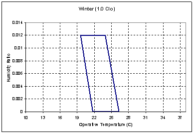
Figure 39. Winter Comfort Range
Table 13. Summer Clothes (0.5 Clo)
|
Operative Temp(degC) |
Humidity Ratio |
|
23.6 |
0.012 |
|
26.8 |
0.012 |
|
28.3 |
0.000 |
|
25.1 |
0.000 |
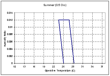
Figure 40. Summer Comfort Range
The time when the zone is occupied that the combination of humidity ratio and operative temperature is not in the ASHRAE 55-2004 summer clothes region (see above)
The time when the zone is occupied that the combination of humidity ratio and operative temperature is not in the ASHRAE 55-2004 winter clothes region (see above)
The time when the zone is occupied that the combination of humidity ratio and operative temperature is not in the ASHRAE 55-2004 summer or winter clothes region (see above)
The time when any zone is occupied that the combination of humidity ratio and operative temperature is not in the ASHRAE 55-2004 summer clothes region (see above)
The time when any zone is occupied that the combination of humidity ratio and operative temperature is not in the ASHRAE 55-2004 winter clothes region (see above)
The time when any zone is occupied that the combination of humidity ratio and operative temperature is not in the ASHRAE 55-2004 summer or winter clothes region (see above)
The simplified ASHRAE 55 calculations may be computed for occupied zones and, possibly, warnings are shown on the .err file at the end of each simulated environment. To enable this option set the “Enable ASHRAE 55 comfort warnings” field of the People object to Yes. These warnings will not be generated by default.
If you enable the warnings, the simplified ASHRAE 55 calculations are done for occupied zones and, possibly, warnings are shown on the .err file at the end of each simulated environment.
** Warning ** More than 4% of time (350.4 hours) uncomfortable in zone ZSF1
** ~~~ ** 553.0 hours were uncomfortable based on ASHRAE 55-2004 graph (Section 5.2.1.1)
** ~~~ ** During Environment [10/01 - 09/30]: CHICAGO IL USA TMY2-94846 WMO#=725300
** Warning ** More than 4% of time (350.4 hours) uncomfortable in zone ZNF1
** ~~~ ** 827.8 hours were uncomfortable based on ASHRAE 55-2004 graph (Section 5.2.1.1)
** ~~~ ** During Environment [10/01 - 09/30]: CHICAGO IL USA TMY2-94846 WMO#=725300
** Warning ** More than 4% of time (350.4 hours) uncomfortable in zone ZSF2
** ~~~ ** 593.5 hours were uncomfortable based on ASHRAE 55-2004 graph (Section 5.2.1.1)
** ~~~ ** During Environment [10/01 - 09/30]: CHICAGO IL USA TMY2-94846 WMO#=725300
** Warning ** More than 4% of time (350.4 hours) uncomfortable in zone ZNF2
** ~~~ ** 875.8 hours were uncomfortable based on ASHRAE 55-2004 graph (Section 5.2.1.1)
** ~~~ ** During Environment [10/01 - 09/30]: CHICAGO IL USA TMY2-94846 WMO#=725300
You may decide if you need to change parameters to reduce these “uncomfortable” hours. The individual report variables shown previously may help you get more details on when these are occurring.
Following are some suggestions that might be applicable:
n Eliminate occupancy when conditioning equipment is off.
n Note that the ASHRAE graph lower limit is (19.6C to 21.7C) – heating setpoints may need to be nearer 22.2C (72F) than 21.1C (70F).
n Unoccupied heating setpoint should be nearer 16.7C (62F) rather than 12.8C (55F) to reduce the start up recovery.
n Start the occupied setpoint schedule, fan availability schedule, cooling pump availability schedule, reheat coil availability, one hour before occupancy. Seasonal turn on and off of equipment may cause more warnings (but potentially more energy consumption).
n Unoccupied cooling setpoint should be nearer 29.4C (85F) rather than 40.0 (104F) to reduce the start up recovery.
When requesting EnergyPlus to do a thermal comfort calculation, the program user has three options for defining how the mean radiant temperature will be calculated. The user may select “zoneaveraged” which results in a mean radiant temperature that is characteristic of an “average” location near the center of the zone. The user may also elect to place the person near a particular surface by selecting “surfaceweighted” in the People statement. This takes the average of the zone mean radiant temperature and the temperature of the surface that the person is near and uses this value as the mean radiant temperature when calculating thermal comfort.
The third option is for the user to more explicitly position the person within the space by defining the angle factors from the person to the various surfaces in the zone. This option requires the user to list the surfaces that the person can see from a radiation standpoint and also define the angle (or view) factor for each surface. The AngleFactorList input line is intended to give the user this opportunity.
This field is an unique user assigned name for the list of surfaces that can be seen radiantly by the person for whom thermal comfort is to be evaluated. Any reference to this list by a People statement will use this name.
Zone Name for this surface list. Each of the surfaces listed must be in this zone.
This field is the name of a surface in the zone seen by the person.
This field is the fraction that this surface contributes to the total mean radiant temperature. This can be thought of as a weighting factor for this surface and the actual mean radiant temperature used in the thermal comfort model is simply the sum of all angle factors multiplied by the corresponding inside surface temperature. Note that the Surface Name/Angle Factor pair can be repeated up to 20 times. The sum of all angle factors within any angle factor list must equal unity, otherwise the program will not accept the input as valid.
An example IDF with an electric low temperature radiant system is shown below.
ComfortViewFactorAngles,
South Zone Angle Factors, !- name of angle factor list
Sourth Zone, !- Zone Name
Zn001:Flr001, !- Surface name 1
0.75, !- Angle factor for surface 1
Zn001:Wall001, !- Surface name 2
0.15, !- Angle factor for surface 2
Zn001:Roof001, !- Surface name 3
0.10; !- Angle factor for surface 3
The Lights statement allows you to specify information about a zone’s electric lighting system, including design power level and operation schedule, and how the heat from lights is distributed thermally.
A zone may have multiple Lights statements. For example, one statement may describe the general lighting in the zone and another the task lighting. Or you can use multiple Lights statements for a zone that has two or more general lighting systems that differ in design level, schedule, etc.
The name of the LIGHTS object.
The field is the name of the thermal zone (ref: Zone) or ZoneList (ref: ZoneLIst) and links this Lights statement to a thermal zone or set of thermal zones in the buidling. When the ZoneList option is used then this lights definition is applied to each of the zones in the zone list effecting a global definition for the amount of light wattage in the zone. This option can be used effectively with the watts/area and watts/person options of the Design Level Calculation Method.
The name of the schedule that modifies the lighting power design level (see next field). The schedule values can be any positive number. The electrical input for lighting in a particular timestep is the product of the design level and the value of this schedule in that timestep. If the design level is the maximum lighting power input the schedule should contain values between 0.0 and 1.0.
This field is a key/choice field that tells which of the next three fields are filled and is descriptive of the method for calculating the nominal lighting level in the Zone. The key/choices are:
n LightingLevel
With this choice, the method used will be a straight insertion of the lighting level (Watts) for the Zone. (The Lighting Level field should be filled.)
n Watts/Area
With this choice, the method used will be a factor per floor area of the zone. (The Watts per Zone Floor Area field should be filled).
n Watts/Person
With this choice, the method used will be a factor of lighting level (watts) per person. (The Watts per person field should be filled).
This is typically the maximum electrical power input (in Watts) to lighting in a zone, including ballasts, if present. This value is multiplied by a schedule fraction (see previous field) to get the lighting power in a particular timestep. In EnergyPlus, this is slightly more flexible in that the lighting design level could be a “diversity factor” applied to a schedule of real numbers.
This factor (watts/m2) is used, along with the Zone Floor Area to determine the maximum lighting level as described in the Lighting Level field. The choice from the method field should be “watts/area”.
This factor (watts/person) is used, along with the number of occupants (people) to determine the maximum lighting level as described in the Lighting Level field. The choice from the method field should be “watts/person”.
The electrical input to lighting ultimately appears as heat that contributes to zone loads or to return air heat gains. In EnergyPlus this heat is divided into four different fractions. Three of these are given by the input fields Return Air Fraction, Fraction Radiant and Fraction Visible. A fourth, defined as the fraction of the heat from lights convected to the zone air, is calculated by the program as:
fconvected = 1.0 – (Return Air Fraction + Fraction Radiant + Fraction Visible)
You will get an error message if Return Air Fraction + Fraction Radiant + Fraction Visible exceeds 1.0.
These fractions depend on the type of lamp and luminaire, whether the luminaire is vented to the return air, etc.
The fraction of the heat from lights that goes into the zone return air (i.e., into the zone outlet node). If the return air flow is zero or the zone has no return air system, the program will put this fraction into the zone air. Return Air Fraction should be non-zero only for luminaires that are return-air ducted (see Table 14 and Figure 41). (However, see the field “Return Air Fraction Is Calculated from Plenum Temperature,” below, for an approach to modeling the case where Return Air Fraction is caused by conduction between a luminaire that is in contact with a return-air plenum.)
The fraction of heat from lights that goes into the zone as long-wave (thermal) radiation. The program calculates how much of this radiation is absorbed by the inside surfaces of the zone according the area times thermal absorptance product of these surfaces.
The fraction of heat from lights that goes into the zone as visible (short-wave) radiation. The program calculates how much of this radiation is absorbed by the inside surfaces of the zone according the area times solar absorptance product of these surfaces.
Approximate values of Return Air Fraction, Fraction Radiant and Fraction Visible are given in Table 14 for overhead fluorescent lighting for the luminaire configurations shown in Figure 41.
Table 14. Approximate values of Return Air Fraction, Fraction Radiant and Fraction Visible for overhead fluorescent lighting for different luminaire configurations. These values assume that no light heat goes into an adjacent zone. Source: Lighting Handbook: Reference & Application, 8th Edition, Illuminating Engineering Society of North America, New York, 1993, p. 355.
|
Field Name |
Luminaire Configuration, Fluorescent Lighting |
||||
|
Suspended |
Surface |
Recessed |
Luminous |
Return-air |
|
|
Return Air Fraction |
0.0 |
0.0 |
0.0 |
0.0 |
0.54 |
|
Fraction Radiant |
0.42 |
0.72 |
0.37 |
0.37 |
0.18 |
|
Fraction Visible |
0.18 |
0.18 |
0.18 |
0.18 |
0.18 |
|
fconvected |
0.40 |
0.10 |
0.45 |
0.45 |
0.10 |
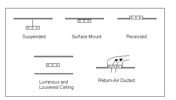
Figure 41. Overhead fluorescent luminaire configurations.
This field defines the daylighting control for the LIGHTS object.
If Daylighting:Controls or Daylighting:DELight:Controls is specified for the zone, this field is used as an on/off flag for dimming controls. If set to 0.0, the lights are not dimmed by the daylighting controls. If set to 1.0, the lights are allowed to be dimmed by the daylighting controls.
Allows you to specify a user-defined end-use subcategory, e.g., "Task Lights", "Hall Lights", etc. A new meter for reporting is created for each unique subcategory (ref: Output:Meter and). Subcategories are also reported in the ABUPS table. If this field is omitted or blank, the lights will be assigned to the "General" end-use subcategory.
Accepts values Yes or No (the default). Yes is for advanced used only. In this case the program will calculate the return air fraction by assuming that it is due to conduction of some of the light heat into the zone’s return air plenum and that the amount of the conduction depends on the plenum air temperature. A Yes value should only be used for luminaires that are recessed and non-vented, as shown in Figure 42.
The value you enter for the Return Air Fraction field will be ignored and you can enter, for fluorescent lighting, Fraction Radiant = 0.37 and Fraction Visible = 0.18, as indicated in Table 14.
This feature requires that the coefficients described below be determined from measurements or detailed calculations since they are very sensitive to the luminaire type, lamp type, thermal resistance between fixture and plenum, etc.
If “Return Air Fraction Is Calculated from Plenum Temperature” = Yes, the return air fraction is calculated each timestep from the following empirical correlation:
(Return Air Fraction)calculated = C1 – C2 x Tplenum
where Tplenum is the previous-time-step value of the return plenum air temperature (deg C), and C1 and C2 are the values of the coefficients entered in the next two fields.
To compensate for the change in the return air fraction relative to its input value, the program modifies Fraction Radiant and fconvected by a scale factor such that
(Return Air Fraction)calculated + (Fraction Radiant)modified + (fconvected)modified + (Fraction Visible)input = 1.0
It is assumed that Fraction Visible is a constant equal to its input value.
The coefficient C1 in the equation for (Return Air Fraction)calculated.
The coefficient C2 in the equation for (Return Air Fraction)calculated. Its units are 1/OC.
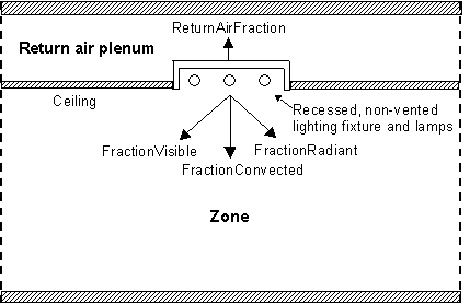
Figure 42. Vertical section through a zone and its return air plenum showing recessed lighting (not to scale). The heat from lights is divided into four fractions, three of which—ReturnAirFraction, FractionRadiant and FractionConvected—depend on plenum air temperature.
An IDF example:
Lights,
RIGHT FORK Lights 1, !- Name
RIGHT FORK, !- Zone Name
Office Lighting, !- SCHEDULE Name
LightingLevel, !- Design Level calculation method
1039.706,,, !- Lighting Level {W}
0.0000000E+00, !- Return Air Fraction
0.4000000, !- Fraction Radiant
0.2000000, !- Fraction Visible
1.0, !- Fraction Replaceable
GeneralLights; !- End-Use Subcategory
Global Lights Object:
ZoneList,AllOccupiedZones,SPACE1-1,SPACE2-1,SPACE3-1,SPACE4-1,SPACE5-1;
Lights,
AllZones with Lights, !- Name
AllOccupiedZones, !- Zone or ZoneList Name
LIGHTS-1, !- Schedule Name
Watts/Area, !- Design Level Calculation Method
, !- Lighting Level {W}
16, !- Watts per Zone Floor Area {W/m2}
, !- Watts per Person {W/person}
0.2, !- Return Air Fraction
0.59, !- Fraction Radiant
0.2, !- Fraction Visible
0, !- Fraction Replaceable
GeneralLights; !- End-Use Subcategory
If daylighting controls are operating in the zone, all of the Lights objects with a Fraction Replaceble greater than zero will be reduced by a multiplicative factor that accounts for how much the electric lighting is lowered due to daylighting.
Lights objects have output variables for individual objects and for zone totals.
Zone,Average,Lights Electric Power [W]
Zone,Sum,Lights Radiant Heat Gain [J]
Zone,Average,Lights Radiant Heat Gain Rate [W]
Zone,Sum,Lights Visible Heat Gain [J]
Zone,Average,Lights Visible Heat Gain Rate [W]
Zone,Sum,Lights Convective Heat Gain [J]
Zone,Average,Lights Convective Heat Gain Rate [W]
Zone,Sum,Lights Return Air Heat Gain [J]
Zone,Average,Lights Return Air Heat Gain Rate [W]
Zone,Sum,Lights Total Heat Gain [J]
Zone,Average,Lights Total Heat Gain Rate [W]
Zone,Sum,Lights Electric Consumption [J]
Zone,Average,Zone Lights Electric Power [W]
Zone,Sum,Zone Lights Radiant Heat Gain [J]
Zone,Average,Zone Lights Radiant Heat Gain Rate [W]
Zone,Sum,Zone Lights Visible Heat Gain [J]
Zone,Average,Zone Lights Visible Heat Gain Rate [W]
Zone,Sum,Zone Lights Convective Heat Gain [J]
Zone,Average,Zone Lights Convective Heat Gain Rate [W]
Zone,Sum,Zone Lights Return Air Heat Gain [J]
Zone,Average,Zone Lights Return Air Heat Gain Rate [W]
Zone,Sum,Zone Lights Total Heat Gain [J]
Zone,Average,Zone Lights Total Heat Gain Rate [W]
Zone,Sum,Zone Lights Electric Consumption [J]
The electric power input for the lights.
The amount of heat gain from lights that is in the form of long-wave (thermal) radiation entering the zone. This heat is absorbed by the inside surfaces of the zone according to an area times long-wave absorptance weighting scheme.
The amount of heat gain from lights that is in the form of visible (short-wave) radiation entering the zone. This heat is absorbed by the inside surfaces of the zone according to an area times short-wave absorptance weighting scheme.
The amount of heat gain from lights that is convected to the zone air.
The amount of heat gain from lights that goes into the zone’s return air (and, therefore, does not directly contribute to the zone load). If the zone has no return air system or the zone’s air system is off, this heat will be added to the zone air.
The total heat gain from lights. It is the sum of the following four outputs, i.e., Total Heat Gain = Return Air Heat Gain + Radiant Heat Gain + Visible Heat Gain + Convective Heat Gain. It is also equal to the electrical input to the lights.
The lighting electrical consumption including ballasts, if present. These will have the same value as Lights Total Heat Gain (above).
The electric power input for all lights in the zone.
The amount of heat gain from all lights in the zone that is in the form of long-wave (thermal) radiation entering the zone. This heat is absorbed by the inside surfaces of the zone according to an area times long-wave absorptance weighting scheme.
The amount of heat gain from all lights in the zone that is in the form of visible (short-wave) radiation entering the zone. This heat is absorbed by the inside surfaces of the zone according to an area times short-wave absorptance weighting scheme.
The amount of heat gain from all lights in the zone that is convected to the zone air.
The amount of heat gain from all lights in the zone that goes into the zone’s return air (and, therefore, does not directly contribute to the zone load). If the zone has no return air system or the zone’s air system is off, this heat will be added to the zone air.
The total heat gain from all lights in the zone. It is the sum of the following four outputs, i.e., Total Heat Gain = Return Air Heat Gain + Radiant Heat Gain + Visible Heat Gain + Convective Heat Gain. It is also equal to the electrical input to the lights.
The lighting electrical consumption for all lights in the zone including ballasts, if present. This will have the same value as Zone Lights Total Heat Gain (above). However, this amount is also shown in the Electricity meters that are associated with the zone:
Electricity:Facility,
Electricity:Building,
Electricity:Zone:<Zone Name>.
In addition, depending on use, it will be shown in:
InteriorLights: Electricity and
InteriorLights:Electricity:Zone :<Zone Name>.
As described in the Lights Outputs, values for lights will show up on the following meters:
Table 15. Distribution of Lights to Meters
|
Meter Name |
Scope |
Lights Specfics |
|
Electricity:Facility |
Entire Facility |
All |
|
Electricity:Building |
All Zones |
All |
|
Electricity:Zone:<Zone Name> |
Specific Zone |
All |
|
InteriorLights:Electricity |
All Zones |
Lights Use |
|
InteriorLights:Electricity:Zone:<Zone Name> |
Specific Zone |
Lights Use |
|
<End-Use Subcategory>:InteriorLights:Electricity |
Specific Subcategory |
Lights Use |
The name of the ElectricEquipment object.
This field is the name of the zone (ref: Zone) or ZoneList (ref: ZoneList) and attaches a particular electric equipment statement to a thermal zone or set of thermal zones in the building. When the ZoneList option is used then this electric equipment definition is applied to each of the zones in the zone list effecting a global definition for the amount of electric wattage in the zone. This option can be used effectively with the watts/area and watts/person options of the Design Level Calculation Method.
This field is the name of the schedule that modifies the design level parameter for electric equipment (see next field). The schedule values can be any positive number. The actual electrical input for equipment in a zone as defined by this statement is the product of the design level field and the value of the schedule specified by name in this field.
This field is a key/choice field that tells which of the next three fields are filled and is descriptive of the method for calculating the nominal electric equipment level in the Zone. The key/choices are:
n EquipmentLevel
With this choice, the method used will be a straight insertion of the electric equipment level (Watts) for the Zone. (The Design Level field should be filled.)
n Watts/Area
With this choice, the method used will be a factor per floor area of the zone. (The Watts per Zone Floor Area field should be filled).
n Watts/Person
With this choice, the method used will be a factor of equipment level (watts) per person. (The Watts per Person field should be filled).
This field (in Watts) is typically used to represent the maximum electrical input to equipment in a zone that is then multiplied by a schedule fraction (see previous field). In EnergyPlus, this is slightly more flexible in that the electric equipment design level could be a “diversity factor” applied to a schedule of real numbers. Note that while the schedule value can vary from hour to hour, the design level field is constant for all simulation environments.
This factor (watts/m2) is used, along with the Zone Area to determine the maximum equipment level as described in the Design Level field. The choice from the method field should be “Watts/Area”.
This factor (watts/person) is used, along with the number of occupants (people) to determine the maximum equipment level as described in the Design Level field. The choice from the method field should be “Watts/Person”.
The electrical input to the equipment ultimately appears as heat that contributes to zone loads. In EnergyPlus this heat is divided into four different fractions. Three of these are given by the input fields Fraction Latent, Fraction Radiant and Fraction Lost. A fourth, defined as the fraction of the heat from electric equipment convected to the zone air, is calculated by the program as:
fconvected = 1.0 – (Fraction Latent + Fraction Radiant + Fraction Lost)
You will get an error message if Fraction Latent + Fraction Radiant + Fraction Lost exceeds 1.0.
This field is a decimal number between 0.0 and 1.0 and is used to characterize the amount of latent heat given off by electric equipment in a zone. The number specified in this field will be multiplied by the total energy consumed by electric equipment to give the amount of latent energy produced by the electric equipment. This energy affects the moisture balance within the zone.
This field is a decimal number between 0.0 and 1.0 and is used to characterize the amount of long-wave radiant heat being given off by electric equipment in a zone. The number specified in this field will be multiplied by the total energy consumed by electric equipment to give the amount of long wavelength radiation gain from electric equipment in a zone.
This field is a decimal number between 0.0 and 1.0 and is used to characterize the amount of “lost” heat being given off by electric equipment in a zone. The number specified in this field will be multiplied by the total energy consumed by electric equipment to give the amount of heat which is “lost” and does not impact the zone energy balances. This might correspond to electrical energy converted to mechanical work or heat that is vented to the atmosphere.
Allows you to specify a user-defined end-use subcategory, e.g., "Computers", "Copy Machines", etc. A new meter for reporting is created for each unique subcategory (ref: Report Meter). Subcategories are also reported in the ABUPS table. If this field is omitted or blank, the equipment will be assigned to the "General" end-use subcategory.
An IDF example:
ElectricEquipment,
DORM ROOMS AND COMMON AREAS ElecEq 1, !- Name
DORM ROOMS AND COMMON AREAS, !- Zone Name
Residence Equipment, !- SCHEDULE Name
EquipmentLevel, !- Design Level calculation method
9210.921, !- Design Level {W}
, !- Watts per Zone Floor Area {watts/m2}
, !- Watts per Person {watts/person}
0.0000000E+00, !- Fraction Latent
0.3000000, !- Fraction Radiant
0.0000000E+00, !- Fraction Lost
Computers; !- End-use Subcategory
Global ElectricEquipment example:
ZoneList,AllOccupiedZones,SPACE1-1,SPACE2-1,SPACE3-1,SPACE4-1,SPACE5-1;
ElectricEquipment,
AllZones with Electric Equipment, !- Name
AllOccupiedZones, !- Zone or ZoneList Name
EQUIP-1, !- Schedule Name
Watts/Person, !- Design Level Calculation Method
, !- Design Level {W}
, !- Watts per Zone Floor Area {W/m2}
96, !- Watts per Person {W/person}
0, !- Fraction Latent
0.3, !- Fraction Radiant
0; !- Fraction Lost
The name of the GasEquipment object.
This field is the name of the thermal zone (ref: Zone) or ZoneList (ref: ZoneList) and attaches a particular gas equipment statement to a thermal zone or set of thermal zones in the building. When the ZoneList option is used then this gas equipment definition is applied to each of the zones in the zone list effecting a global definition for the amount of gas in the zone. This option can be used effectively with the watts/area and watts/person options of the Design Level Calculation Method.
This field is the name of the schedule that modifies the design level parameter for gas equipment (see next field). The schedule values can be any positive number. The actual energy input for gas equipment in a zone as defined by this statement is the product of the design level field and the value of the schedule specified by name in this field.
This field is a key/choice field that tells which of the next three fields are filled and is descriptive of the method for calculating the nominal gas equipment level in the Zone. The key/choices are:
n EquipmentLevel
With this choice, the method used will be a straight insertion of the gas equipment level (Watts) for the Zone. (The Design Level field should be filled.)
n Watts/Area
With this choice, the method used will be a factor per floor area of the zone. (The Watts per Zone Floor Area field should be filled).
n Watts/Person
With this choice, the method used will be a factor of equipment level (watts) per person. (The Watts per person field should be filled).
This field (in Watts) is typically used to represent the maximum energy input to gas equipment in a zone that is then multiplied by a schedule fraction (see previous field). In EnergyPlus, this is slightly more flexible in that the gas equipment design level could be a “diversity factor” applied to a schedule of real numbers. Note that while the schedule value can vary from hour to hour, the design level field is constant for all simulation environments.
This factor (watts/m2) is used, along with the Zone Area to determine the maximum equipment level as described in the Design Level field. The choice from the method field should be “Watts/Area”.
This factor (watts/person) is used, along with the number of occupants (people) to determine the maximum equipment level as described in the Design Level field. The choice from the method field should be “Watts/Person”.
The fuel input to the equipment ultimately appears as heat that contributes to zone loads. In EnergyPlus this heat is divided into four different fractions. Three of these are given by the input fields Fraction Latent, Fraction Radiant and Fraction Lost. A fourth, defined as the fraction of the heat from gas equipment convected to the zone air, is calculated by the program as:
fconvected = 1.0 – (Fraction Latent + Fraction Radiant + Fraction Lost)
You will get an error message if Fraction Latent + Fraction Radiant + Fraction Lost exceeds 1.0.
This field is a decimal number between 0.0 and 1.0 and is used to characterize the amount of latent heat given off by gas equipment in a zone. The number specified in this field will be multiplied by the total energy consumed by gas equipment to give the amount of latent energy produced by the gas equipment. This energy affects the moisture balance within the zone.
This field is a decimal number between 0.0 and 1.0 and is used to characterize the amount of long-wave radiant heat being given off by gas equipment in a zone. The number specified in this field will be multiplied by the total energy consumed by gas equipment to give the amount of long wavelength radiation gain from gas equipment in a zone.
This field is a decimal number between 0.0 and 1.0 and is used to characterize the amount of “lost” heat being given off by gas equipment in a zone. The number specified in this field will be multiplied by the total energy consumed by gas equipment to give the amount of heat which is “lost” and does not impact the zone energy balances. This might correspond to input energy converted to mechanical work or heat that is vented to the atmosphere.
This numeric input field specifies carbon dioxide generation rate with units of m3/s-W. The default value of 0.0 assumes the equipment is fully vented to outdoors. In the absence of better information, the user might consider using a value of 3.45E-8 m3/s-W which assumes the equipment is not vented to outdoors. This value is converted from natural gas CO2 emission rate at 11.7 lbs CO2 per therm. The CO2 emission rate is provided by U.S. Energy Information Administration, "Frequently Asked Questions - Environment, Questions About Environmental Emissions", http://tonto.eia.doe.gov/ask/environment_faqs.asp#CO2_quantity, January 2010. The maximum value for this input field is 3.45E-7 m3/s-W.
Allows you to specify a user-defined end-use subcategory, e.g., "Cooking", "Clothes Drying", etc. A new meter for reporting is created for each unique subcategory (ref: Report Meter). Subcategories are also reported in the ABUPS table. If this field is omitted or blank, the equipment will be assigned to the "General" end-use subcategory.
An IDF example:
GasEquipment,
DORM ROOMS AND COMMON AREAS GasEq 1, !- Name
DORM ROOMS AND COMMON AREAS, !- Zone Name
Gas Eq Sch, !- Schedule Name
EquipmentLevel, !- Design Level Calculation Method
29287.51, !- Design Level {W}
, !- Watts per Zone Floor Area {W/m2}
, !- Watts per Person {W/Person}
0, !- Fraction Latent
0.3, !- Fraction Radiant
0, !- Fraction Lost
0, !- Carbon Dioxide Generation Rate {m3/s-W}
Cooking; !- End-Use Subcategory
Global Gas Equipment example:
ZoneList,OfficeZones,Left Fork, Middle Fork, Right Fork;
GasEquipment,
Office Zones with Gas Equipment, !- Name
OfficeZones, !- Zone Name
Gas Eq Sch, !- Schedule Name
Watts/Area, !- Design Level Calculation Method
, !- Design Level {W}
197, !- Watts per Zone Floor Area {W/m2}
, !- Watts per Person {W/Person}
0.0000000E+00, !- Fraction Latent
0.3000000, !- Fraction Radiant
0.0000000E+00; !- Fraction Lost
The name of the HotWaterEquipment object.
This field is the name of the thermal zone (ref: Zone) or ZoneList (ref: ZoneList) and attaches a particular hot water equipment statement to a thermal zone or set of thermal zones in the building. When the ZoneList option is used then this hot water equipment definition is applied to each of the zones in the zone list effecting a global definition for the amount of hot water in the zone. This option can be used effectively with the watts/area and watts/person options of the Design Level Calculation Method.
This field is the name of the schedule that modifies the design level parameter for hot water equipment (see next field). The schedule values can be any positive number. The actual energy input for hot water equipment in a zone as defined by this statement is the product of the design level field and the value of the schedule specified by name in this field.
This field is a key/choice field that tells which of the next three fields are filled and is descriptive of the method for calculating the nominal hot water equipment level in the Zone. The key/choices are:
n EquipmentLevel
With this choice, the method used will be a straight insertion of the hot water equipment level (Watts) for the Zone. (The Design Level field should be filled.)
n Watts/Area
With this choice, the method used will be a factor per floor area of the zone. (The Watts per Zone Floor Area field should be filled).
n Watts/Person
With this choice, the method used will be a factor of equipment level (watts) per person. (The Watts per person field should be filled).
This field (in Watts) is typically used to represent the maximum energy input to hot water equipment in a zone that is then multiplied by a schedule fraction (see previous field). In EnergyPlus, this is slightly more flexible in that the hot water equipment design level could be a “diversity factor” applied to a schedule of real numbers. Note that while the schedule value can vary from hour to hour, the design level field is constant for all simulation environments.
This factor (watts/m2) is used, along with the Zone Area to determine the maximum equipment level as described in the Design Level field. The choice from the method field should be “Watts/Area”.
This factor (watts/person) is used, along with the number of occupants (people) to determine the maximum equipment level as described in the Design Level field. The choice from the method field should be “Watts/Person”.
The fuel input to the equipment ultimately appears as heat that contributes to zone loads. In EnergyPlus this heat is divided into four different fractions. Three of these are given by the input fields Fraction Latent, Fraction Radiant and Fraction Lost. A fourth, defined as the fraction of the heat from hot water equipment convected to the zone air, is calculated by the program as:
fconvected = 1.0 – (Fraction Latent + Fraction Radiant + Fraction Lost)
You will get an error message if Fraction Latent + Fraction Radiant + Fraction Lost exceeds 1.0.
This field is a decimal number between 0.0 and 1.0 and is used to characterize the amount of latent heat given off by hot water equipment in a zone. The number specified in this field will be multiplied by the total energy consumed by hot water equipment to give the amount of latent energy produced by the hot water equipment. This energy affects the moisture balance within the zone.
This field is a decimal number between 0.0 and 1.0 and is used to characterize the amount of long-wave radiant heat being given off by hot water equipment in a zone. The number specified in this field will be multiplied by the total energy consumed by hot water equipment to give the amount of long wavelength radiation gain from hot water equipment in a zone.
This field is a decimal number between 0.0 and 1.0 and is used to characterize the amount of “lost” heat being given off by hot water equipment in a zone. The number specified in this field will be multiplied by the total energy consumed by hot water equipment to give the amount of heat which is “lost” and does not impact the zone energy balances. This might correspond to input energy converted to mechanical work or heat that is vented to the atmosphere.
Allows you to specify a user-defined end-use subcategory, e.g., "Cooking", "Clothes Drying", etc. A new meter for reporting is created for each unique subcategory (ref: Report Meter). Subcategories are also reported in the ABUPS table. If this field is omitted or blank, the equipment will be assigned to the "General" end-use subcategory.
IDF Examples:
HotWaterEquipment,
SPACE2-1 HWEq 1, !- Name
SPACE2-1, !- Zone Name
EQUIP-1, !- SCHEDULE Name
EquipmentLevel, !- Design Level calculation method
300, !- Design Level {W}
, !- Watts per Zone Floor Area {watts/m2}
, !- Watts per Person {watts/person}
0.2, !- Fraction Latent
0.1, !- Fraction Radiant
0.5, !- Fraction Lost
Dishwashing; !- End-Use Subcategory
Global Hot Water Equipment example:
ZoneList,OfficeZones,Left Fork, Middle Fork, Right Fork;
HotWaterEquipment,
Office Zones with Hot Water Equipment, !- Name
OfficeZones, !- Zone Name
HotWater Eq Sch, !- Schedule Name
Watts/Area, !- Design Level Calculation Method
, !- Design Level {W}
50, !- Watts per Zone Floor Area {W/m2}
, !- Watts per Person {W/Person}
0.0000000E+00, !- Fraction Latent
0.3000000, !- Fraction Radiant
0.0000000E+00; !- Fraction Lost
The name of the SteamEquipment object.
This field is the name of the thermal zone (ref: Zone) and attaches a particular steam equipment statement to a thermal zone or set of thermal zones in the building. When the ZoneList option is used then this steam equipment definition is applied to each of the zones in the zone list effecting a global definition for the amount of steam in the zone. This option can be used effectively with the watts/area and watts/person options of the Design Level Calculation Method.
This field is the name of the schedule that modifies the design level parameter for steam equipment (see next field). The schedule values can be any positive number. The actual energy input for steam equipment in a zone as defined by this statement is the product of the design level field and the value of the schedule specified by name in this field.
This field is a key/choice field that tells which of the next three fields are filled and is descriptive of the method for calculating the nominal steam equipment level in the Zone. The key/choices are:
n EquipmentLevel
With this choice, the method used will be a straight insertion of the steam equipment level (Watts) for the Zone. (The Design Level field should be filled.)
n Watts/Area
With this choice, the method used will be a factor per floor area of the zone. (The Watts per Zone Floor Area field should be filled).
n Watts/Person
With this choice, the method used will be a factor of equipment level (watts) per person. (The Watts per person field should be filled).
This field (in Watts) is typically used to represent the maximum energy input to steam equipment in a zone that is then multiplied by a schedule fraction (see previous field). In EnergyPlus, this is slightly more flexible in that the steam equipment design level could be a “diversity factor” applied to a schedule of real numbers. Note that while the schedule value can vary from hour to hour, the design level field is constant for all simulation environments.
This factor (watts/m2) is used, along with the Zone Area to determine the maximum equipment level as described in the Design Level field. The choice from the method field should be “Watts/Area”.
This factor (watts/person) is used, along with the number of occupants (people) to determine the maximum equipment level as described in the Design Level field. The choice from the method field should be “Watts/Person”.
The fuel input to the equipment ultimately appears as heat that contributes to zone loads. In EnergyPlus this heat is divided into four different fractions. Three of these are given by the input fields Fraction Latent, Fraction Radiant and Fraction Lost. A fourth, defined as the fraction of the heat from steam equipment convected to the zone air, is calculated by the program as:
fconvected = 1.0 – (Fraction Latent + Fraction Radiant + Fraction Lost)
You will get an error message if Fraction Latent + Fraction Radiant + Fraction Lost exceeds 1.0.
This field is a decimal number between 0.0 and 1.0 and is used to characterize the amount of latent heat given off by steam equipment in a zone. The number specified in this field will be multiplied by the total energy consumed by steam equipment to give the amount of latent energy produced by the steam equipment. This energy affects the moisture balance within the zone.
This field is a decimal number between 0.0 and 1.0 and is used to characterize the amount of long-wave radiant heat being given off by steam equipment in a zone. The number specified in this field will be multiplied by the total energy consumed by steam equipment to give the amount of long wavelength radiation gain from steam equipment in a zone.
This field is a decimal number between 0.0 and 1.0 and is used to characterize the amount of “lost” heat being given off by steam equipment in a zone. The number specified in this field will be multiplied by the total energy consumed by steam equipment to give the amount of heat which is “lost” and does not impact the zone energy balances. This might correspond to input energy converted to mechanical work or heat that is vented to the atmosphere.
Allows you to specify a user-defined end-use subcategory, e.g., "Cooking", "Clothes Drying", etc. A new meter for reporting is created for each unique subcategory (ref: Report Meter). Subcategories are also reported in the ABUPS table. If this field is omitted or blank, the equipment will be assigned to the "General" end-use subcategory.
IDF Examples:
SteamEquipment,
SPACE4-1 ElecEq 1, !- Name
SPACE4-1, !- Zone Name
EQUIP-1, !- SCHEDULE Name
EquipmentLevel, !- Design Level calculation method
1050, !- Design Level {W}
, !- Watts per Zone Floor Area {watts/m2}
, !- Watts per Person {watts/person}
0.5, !- Fraction Latent
0.3, !- Fraction Radiant
0, !- Fraction Lost
Laundry; !- End-Use Subcategory
Other Equipment object is provided as an additional source for heat gains or losses directly to the zone. That is to say, a loss can be entered by putting a negative value into the Design Level field(s). Note, too, that this object does not have an end-use component – gains or losses do not show up in the bottom energy lines (except as influencing overall zone gains or losses).
The name of the OtherEquipment object.
This field is the name of the thermal zone (ref: Zone) and attaches a particular other equipment statement to a thermal zone or set of thermal zones in the building. When the ZoneList option is used then this other equipment definition is applied to each of the zones in the zone list effecting a global definition for the amount of other in the zone. This option can be used effectively with the watts/area and watts/person options of the Design Level Calculation Method.
This field is the name of the schedule that modifies the design level parameter for other equipment (see next field). The schedule values can be any positive number. The actual energy input for other equipment in a zone as defined by this statement is the product of the design level field and the value of the schedule specified by name in this field.
This field is a key/choice field that tells which of the next three fields are filled and is descriptive of the method for calculating the nominal other equipment level in the Zone. The key/choices are:
n EquipmentLevel
With this choice, the method used will be a straight insertion of the other equipment level (Watts) for the Zone. (The Design Level field should be filled.)
n Watts/Area
With this choice, the method used will be a factor per floor area of the zone. (The Watts per Zone Floor Area field should be filled).
n Watts/Person
With this choice, the method used will be a factor of equipment level (watts) per person. (The Watts per person field should be filled).
This field (in Watts) is typically used to represent the maximum energy input to other equipment in a zone that is then multiplied by a schedule fraction (see previous field). In EnergyPlus, this is slightly more flexible in that the other equipment design level could be a “diversity factor” applied to a schedule of real numbers. This value can be negative to denote a loss. Note that while the schedule value can vary from hour to hour, the design level field is constant for all simulation environments.
This factor (watts/m2) is used, along with the Zone Area to determine the maximum equipment level as described in the Design Level field. This value can be negative to denote a loss. The choice from the method field should be “Watts/Area”.
This factor (watts/person) is used, along with the number of occupants (people) to determine the maximum equipment level as described in the Design Level field. This value can be negative to denote a loss. The choice from the method field should be “Watts/Person”.
The fuel input to the equipment ultimately appears as heat that contributes to zone loads. In EnergyPlus this heat is divided into four different fractions. Three of these are given by the input fields Fraction Latent, Fraction Radiant and Fraction Lost. A fourth, defined as the fraction of the heat from other equipment convected to the zone air, is calculated by the program as:
fconvected = 1.0 – (Fraction Latent + Fraction Radiant + Fraction Lost)
You will get an error message if Fraction Latent + Fraction Radiant + Fraction Lost exceeds 1.0.
This field is a decimal number between 0.0 and 1.0 and is used to characterize the amount of latent heat given off by other equipment in a zone. The number specified in this field will be multiplied by the total energy consumed by other equipment to give the amount of latent energy produced by the other equipment. This energy affects the moisture balance within the zone.
This field is a decimal number between 0.0 and 1.0 and is used to characterize the amount of long-wave radiant heat being given off by other equipment in a zone. The number specified in this field will be multiplied by the total energy consumed by other equipment to give the amount of long wavelength radiation gain from other equipment in a zone.
This field is a decimal number between 0.0 and 1.0 and is used to characterize the amount of “lost” heat being given off by other equipment in a zone. The number specified in this field will be multiplied by the total energy consumed by other equipment to give the amount of heat which is “lost” and does not impact the zone energy balances. This might correspond to input energy converted to mechanical work or heat that is vented to the atmosphere.
IDF Examples
OtherEquipment,
BASE-1 OthEq 1, !- Name
BASE-1, !- Zone Name
ALWAYSON, !- SCHEDULE Name
EquipmentLevel, !- Design Level calculation method
6766., !- Design Level {W}
, !- Watts per Zone Floor Area {watts/m2}
, !- Watts per Person {watts/person}
0, !- Fraction Latent
0.3, !- Fraction Radiant
0; !- Fraction Lost
Each type of equipment object has output variables for individual objects and for zone totals.
Electric Equipment
Zone,Average,Electric Equipment Electric Power [W]
Zone,Sum,Electric Equipment Electric Consumption [J]
Zone,Sum,Electric Equipment Radiant Heat Gain [J]
Zone,Average,Electric Equipment Radiant Heat Gain Rate [W]
Zone,Sum,Electric Equipment Convective Heat Gain [J]
Zone,Average,Electric Equipment Convective Heat Gain Rate [W]
Zone,Sum,Electric Equipment Latent Heat Gain [J]
Zone,Average,Electric Equipment Latent Heat Gain Rate [W]
Zone,Sum,Electric Equipment Lost Heat Gain [J]
Zone,Average,Electric Equipment Lost Heat Gain Rate [W]
Zone,Sum,Electric Equipment Total Heat Gain [J]
Zone,Average,Electric Equipment Total Heat Gain Rate [W]
Zone,Average,Zone Electric Equipment Electric Power [W]
Zone,Sum,Zone Electric Equipment Electric Consumption [J]
Zone,Sum,Zone Electric Equipment Radiant Heat Gain [J]
Zone,Average,Zone Electric Equipment Radiant Heat Gain Rate [W]
Zone,Sum,Zone Electric Equipment Convective Heat Gain [J]
Zone,Average,Zone Electric Equipment Convective Heat Gain Rate [W]
Zone,Sum,Zone Electric Equipment Latent Heat Gain [J]
Zone,Average,Zone Electric Equipment Latent Heat Gain Rate [W]
Zone,Sum,Zone Electric Equipment Lost Heat Gain [J]
Zone,Average,Zone Electric Equipment Lost Heat Gain Rate [W]
Zone,Sum,Zone Electric Equipment Total Heat Gain [J]
Zone,Average,Zone Electric Equipment Total Heat Gain Rate [W]
Gas Equipment
Zone,Average,Gas Equipment Gas Consumption Rate [W]
Zone,Sum,Gas Equipment Gas Consumption [J]
Zone,Sum,Gas Equipment Radiant Heat Gain [J]
Zone,Sum,Gas Equipment Convective Heat Gain [J]
Zone,Sum,Gas Equipment Latent Heat Gain [J]
Zone,Sum,Gas Equipment Lost Heat Gain [J]
Zone,Sum,Gas Equipment Total Heat Gain [J]
Zone,Average,Gas Equipment Radiant Heat Gain Rate [W]
Zone,Average,Gas Equipment Convective Heat Gain Rate [W]
Zone,Average,Gas Equipment Latent Heat Gain Rate [W]
Zone,Average,Gas Equipment Lost Heat Gain Rate [W]
Zone,Average,Gas Equipment Total Heat Gain Rate [W]
Zone,Average,Zone Gas Equipment Gas Consumption Rate [W]
Zone,Sum,Zone Gas Equipment Gas Consumption [J]
Zone,Sum,Zone Gas Equipment Radiant Heat Gain [J]
Zone,Average,Zone Gas Equipment Radiant Heat Gain Rate [W]
Zone,Sum,Zone Gas Equipment Convective Heat Gain [J]
Zone,Average,Zone Gas Equipment Convective Heat Gain Rate [W]
Zone,Sum,Zone Gas Equipment Latent Heat Gain [J]
Zone,Average,Zone Gas Equipment Latent Heat Gain Rate [W]
Zone,Sum,Zone Gas Equipment Lost Heat Gain [J]
Zone,Average,Zone Gas Equipment Lost Heat Gain Rate [W]
Zone,Sum,Zone Gas Equipment Total Heat Gain [J]
Zone,Average,Zone Gas Equipment Total Heat Gain Rate [W]
HotWater Equipment
Zone,Average,Hot Water Equipment District Heating Consumption Rate [W]
Zone,Sum,Hot Water Equipment District Heating Consumption [J]
Zone,Sum,Hot Water Equipment Radiant Heat Gain [J]
Zone,Average,Hot Water Equipment Radiant Heat Gain Rate [W]
Zone,Sum,Hot Water Equipment Convective Heat Gain [J]
Zone,Average,Hot Water Equipment Convective Heat Gain Rate [W]
Zone,Sum,Hot Water Equipment Latent Heat Gain [J]
Zone,Average,Hot Water Equipment Latent Heat Gain Rate [W]
Zone,Sum,Hot Water Equipment Lost Heat Gain [J]
Zone,Average,Hot Water Equipment Lost Heat Gain Rate [W]
Zone,Sum,Hot Water Equipment Total Heat Gain [J]
Zone,Average,Hot Water Equipment Total Heat Gain Rate [W]
Zone,Average,Zone Hot Water Equipment District Heating Consumption Rate [W]
Zone,Sum,Zone Hot Water Equipment District Heating Consumption [J]
Zone,Sum,Zone Hot Water Equipment Radiant Heat Gain [J]
Zone,Average,Zone Hot Water Equipment Radiant Heat Gain Rate [W]
Zone,Sum,Zone Hot Water Equipment Convective Heat Gain [J]
Zone,Average,Zone Hot Water Equipment Convective Heat Gain Rate [W]
Zone,Sum,Zone Hot Water Equipment Latent Heat Gain [J]
Zone,Average,Zone Hot Water Equipment Latent Heat Gain Rate [W]
Zone,Sum,Zone Hot Water Equipment Lost Heat Gain [J]
Zone,Average,Zone Hot Water Equipment Lost Heat Gain Rate [W]
Zone,Sum,Zone Hot Water Equipment Total Heat Gain [J]
Zone,Average,Zone Hot Water Equipment Total Heat Gain Rate [W]
Steam Equipment
Zone,Average,Steam Equipment District Heating Consumption Rate [W]
Zone,Sum,Steam Equipment District Heating Consumption [J]
Zone,Sum,Steam Equipment Radiant Heat Gain [J]
Zone,Average,Steam Equipment Radiant Heat Gain Rate [W]
Zone,Sum,Steam Equipment Convective Heat Gain [J]
Zone,Average,Steam Equipment Convective Heat Gain Rate [W]
Zone,Sum,Steam Equipment Latent Heat Gain [J]
Zone,Average,Steam Equipment Latent Heat Gain Rate [W]
Zone,Sum,Steam Equipment Lost Heat Gain [J]
Zone,Average,Steam Equipment Lost Heat Gain Rate [W]
Zone,Sum,Steam Equipment Total Heat Gain [J]
Zone,Average,Steam Equipment Total Heat Gain Rate [W]
Zone,Average,Zone Steam Equipment District Heating Consumption Rate [W]
Zone,Sum,Zone Steam Equipment District Heating Consumption [J]
Zone,Sum,Zone Steam Equipment Radiant Heat Gain [J]
Zone,Average,Zone Steam Equipment Radiant Heat Gain Rate [W]
Zone,Sum,Zone Steam Equipment Convective Heat Gain [J]
Zone,Average,Zone Steam Equipment Convective Heat Gain Rate [W]
Zone,Sum,Zone Steam Equipment Latent Heat Gain [J]
Zone,Average,Zone Steam Equipment Latent Heat Gain Rate [W]
Zone,Sum,Zone Steam Equipment Lost Heat Gain [J]
Zone,Average,Zone Steam Equipment Lost Heat Gain Rate [W]
Zone,Sum,Zone Steam Equipment Total Heat Gain [J]
Zone,Average,Zone Steam Equipment Total Heat Gain Rate [W]
Other Equipment
Zone,Sum,Other Equipment Radiant Heat Gain [J]
Zone,Average,Other Equipment Radiant Heat Gain Rate [W]
Zone,Sum,Other Equipment Convective Heat Gain [J]
Zone,Average,Other Equipment Convective Heat Gain Rate [W]
Zone,Sum,Other Equipment Latent Heat Gain [J]
Zone,Average,Other Equipment Latent Heat Gain Rate [W]
Zone,Sum,Other Equipment Lost Heat Gain [J]
Zone,Average,Other Equipment Lost Heat Gain Rate [W]
Zone,Sum,Other Equipment Total Heat Gain [J]
Zone,Average,Other Equipment Total Heat Gain Rate [W]
Zone,Sum,Zone Other Equipment Radiant Heat Gain [J]
Zone,Average,Zone Other Equipment Radiant Heat Gain Rate [W]
Zone,Sum,Zone Other Equipment Convective Heat Gain [J]
Zone,Average,Zone Other Equipment Convective Heat Gain Rate [W]
Zone,Sum,Zone Other Equipment Latent Heat Gain [J]
Zone,Average,Zone Other Equipment Latent Heat Gain Rate [W]
Zone,Sum,Zone Other Equipment Lost Heat Gain [J]
Zone,Average,Zone Other Equipment Lost Heat Gain Rate [W]
Zone,Sum,Zone Other Equipment Total Heat Gain [J]
Zone,Average,Zone Other Equipment Total Heat Gain Rate [W]
This field is the energy consumption rate for the equipment object in Watts.
This field is the amount of radiant heat gain for the equipment object in Watts (for rate) or Joules. This is determined by the current heat gain from the equipment to the zone and the “Fraction Radiant” specified in the input. The radiant gains (long wavelength) are distributed to the surfaces using an area weighting scheme.
This field is the amount of convective heat gain for the equipment object in Watts (for rate) or Joules. This is determined by the current heat gain from the equipment to the zone and the “Fraction Radiant”, “Fraction Lost”, “Fraction Latent” specified in input (1-FractionRadiant-FractionLost-FractionLatent = FractionConvected). The convective heat gain is added to the zone air heat balance directly.
This field is the amount of latent heat gain for the equipment object in Watts (for rate) or Joules. This is determined by the current heat gain from the equipment to the zone and the “Fraction Latent” specified in the input.
This field is the amount of “lost” heat gain for the equipment object in Watts (for rate) or Joules. This is determined by the current heat gain from the equipment to the zone and the “Fraction Lost” specified in the input. This amount does not affect the energy heat balance in the zone.
The total heat gain field is sum of several other fields (radiant, latent, convective). This field is expressed in Watts (for rate) or joules.
The electric equipment consumption field is sum of the other fields (radiant, latent, convective, lost). This field is expressed in joules.
The gas equipment consumption field is sum of the other fields (radiant, latent, convective, lost). This field is expressed in joules.
The equipment consumption field is sum of the other fields (radiant, latent, convective, lost). This field is expressed in joules.
This field is the energy consumption rate for all equipment within the zone in Watts.
This field is the amount of radiant heat gain for all equipment within the zone in Watts (for rate) or Joules. This is determined by the current heat gain from the equipment to the zone and the “Fraction Radiant” specified in the input. The radiant gains (long wavelength) are distributed to the surfaces using an area weighting scheme.
This field is the amount of convective heat gain for all equipment within the zone in Watts (for rate) or Joules. This is determined by the current heat gain from the equipment to the zone and the “Fraction Radiant”, “Fraction Lost”, “Fraction Latent” specified in input (1-FractionRadiant-FractionLost-FractionLatent = FractionConvected). The convective heat gain is added to the zone air heat balance directly.
This field is the amount of latent heat gain for all equipment within the zone in Watts (for rate) or Joules. This is determined by the current heat gain from the equipment to the zone and the “Fraction Latent” specified in the input.
This field is the amount of “lost” heat gain for all equipment within the zone in Watts (for rate) or Joules. This is determined by the current heat gain from the equipment to the zone and the “Fraction Lost” specified in the input. This amount does not affect the energy heat balance in the zone.
The total heat gain field is sum of several other fields (radiant, latent, convective) for all equipment in the zone. This field is expressed in Watts (for rate) or joules.
The electric equipment consumption field is sum of the other fields (radiant, latent, convective, lost) for all equipment in the zone. This field is expressed in joules. This amount is also shown in the Electricity meters that are associated with the zone – Electricity:Facility, Electricity:Buidling, Electricity:Zone:<Zone Name>, and InteriorEquipment:Electricity.
The gas equipment consumption field is sum of the other fields (radiant, latent, convective, lost) for all equipment in the zone. This field is expressed in joules. This amount is also shown in the Gas meters that are associated with the zone – Gas:Facility, Gas:Building, Gas:Zone:<Zone Name>, and InteriorEquipment:Gas. Gas, here, refers to “Natural Gas” fuel.
The equipment consumption field is sum of the other fields (radiant, latent, convective, lost) for all equipment in the zone. This field is expressed in joules. These amounts are shown on the PurchasedHeating meters.
Note that zone energy consumption is not reported for OTHER EQUIPMENT and does not go on any meter.
The ZoneContaminantSourceAndSink:CarbonDioxide object allows users to input carbon dioxide sources or sinks in a zone. Note that carbon dioxide generation within a zone can also be specified using People and GasEquipment objects. Multiple ZoneContaminantSourceAndSink:CarbonDioxide objects can be specified for the same zone.
The name of the ZoneContaminantSourceAndSink:CarbonDioxide object. The name for each ZoneContaminantSourceAndSink:CarbonDioxide object must be unique.
This field is the name of the zone (ref: Zone) and links a particular ZoneContaminantSourceAndSink:CarbonDioxide object to a thermal zone in the building.
This field denotes the design carbon dioxide generation rate (m3/s). The design value is modified by the schedule fraction (see Field: Schedule Name). The resulting volumetric generation rate is converted to mass generation rate using the current zone indoor air density at each time step. The rate can be either positive or negative. A positive value represents a source rate (CO2 addition to the zone air) and a negative value represents a sink rate (CO2 removal from the zone air).
This field is the name of the schedule (ref: Group -- Schedules) that modifies the design carbon dioxide generation rate (see previous field). The schedule values can be any positive number between 0.0 and 1.0. For each simulation time step, the actual CO2 generation rate in a zone is the product of the Design Generation Rate field (above) and the value specified by this schedule.
An IDF example is provided below:
ZoneContaminantSourceAndSink:CarbonDioxide,
NORTH_ZONE CO2, !- Name
NORTH_ZONE, !- Zone Name
1.e-6, !- Design Generation Rate {m3/s}
CO2 Source Schedule; !- Schedule Name
HVAC,Average, Zone CO2 Source and Sink Rate [m3/s]
This output variable reports the total (net) carbon dioxide internal gains/losses in cubic meters per second for a zone, including impacts from three objects: ZoneContaminantSourceAndSink:CarbonDioxide, People, and GasEquipment. Positive values denote carbon dioxide generation (gain or source), while negative values denote carbon dioxide removal (loss or sink).
This object specifies outside temperature-controlled (OTC) baseboard heating. The capacities (high and low) are specified in W at the temperatures specified. The schedule allows both capacities to change hourly on a proportional basis. This baseboard heater does not operate if the outdoor dry-bulb is above the high temperature limit. Between the high temperature and the low temperature, the capacity is interpolated (linear) between the high and the low capacity values. Below the low temperature, the capacity is set at the low capacity value. This allows the user to add baseboard heat to a perimeter zone starting at a prescribed temperature and then slowly increases this capacity to a max value.
Example:
Temperature High = 10 C Capacity High = 100,000 W
Temperature Low = 0 C Capacity Low = 500,000 W
Table 16. Outdoor Temperature Controlled Baseboard Heat Temperature vs. Capacity
|
Outdoor Dry-bulb(C) |
Baseboard Output |
|
>10 |
0 |
|
10 |
100,000 |
|
8 |
180,000 |
|
6 |
260,000 |
|
4 |
340,000 |
|
2 |
420,000 |
|
0 |
500,000 |
|
< 0 |
500,000 |
|
|
|
The name of the ZoneBaseboard:OutdoorTemperatureControlled object.
This field is the name of the zone and attaches the baseboard heat equipment statement to a thermal zone in the building.
This field is the name of the schedule that modifies the capacities (high and low) for baseboard heat equipment (see next field). The schedule values can be any positive number. The actual energy input for the baseboard equipment in a zone as defined by this statement depends on the actual outdoor temperature and where that temperature is in the range of Low Temperature to High Temperature..
This is the baseboard equipment capacity (Watts) at the low temperature limit.
If the outdoor dry-bulb temperature (degrees Celsius) is at or below the low temperature the baseboard heater operates at the low temperature capacity.
This is the baseboard equipment capacity (Watts) at the high temperature limit.
If the outdoor dry-bulb temperature (degrees Celsius) is greater than the high temperature the baseboard heater will not operate.
This field is a decimal number between 0.0 and 1.0 and is used to characterize the type of heat being given off by baseboard heat equipment in a zone. The number specified in this field will be multiplied by the total energy consumed by the baseboard heat equipment to give the amount of long wavelength radiation gain to the zone.
Allows you to specify a user-defined end-use subcategory, e.g., "Perimeter Baseboards", etc. A new meter for reporting is created for each unique subcategory (ref: Report Meter). Subcategories are also reported in the ABUPS table. If this field is omitted or blank, the baseboard equipment will be assigned to the "General" end-use subcategory.
An IDF example:
ZoneBaseboard:OutdoorTemperatureControlled,
SPACE4-1 BBHeat 1, !- Name
SPACE4-1, !- Zone Name
EQUIP-1, !- SCHEDULE Name
1500, !- Capacity at low temperature {W}
0, !- Low Temperature {C}
500, !- Capacity at high temperature {W}
10, !- High Temperature {C}
0.5, !- Fraction Radiant
Baseboard Heat; !- End-Use Subcategory
ZoneBaseboard:OutdoorTemperatureControlled objects have output variables for individual objects and for zone totals. The following outputs are available:
Zone,Average,Baseboard Heat Electric Power [W]
Zone,Sum,Baseboard Heat Electric Consumption [J]
Zone,Sum,Baseboard Heat Radiant Heat Gain [J]
Zone,Average,Baseboard Heat Radiant Heat Gain Rate [W]
Zone,Sum,Baseboard Heat Convective Heat Gain [J]
Zone,Average,Baseboard Heat Convective Heat Gain Rate [W]
Zone,Sum,Baseboard Heat Total Heat Gain [J]
Zone,Average,Baseboard Heat Total Heat Gain Rate [W]
Zone,Average,Zone Baseboard Heat Electric Power [W]
Zone,Sum,Zone Baseboard Heat Electric Consumption [J]
Zone,Sum,Zone Baseboard Heat Radiant Heat Gain [J]
Zone,Average,Zone Baseboard Heat Radiant Heat Gain Rate [W]
Zone,Sum,Zone Baseboard Heat Convective Heat Gain [J]
Zone,Average,Zone Baseboard Heat Convective Heat Gain Rate [W]
Zone,Sum,Zone Baseboard Heat Total Heat Gain [J]
Zone,Average,Zone Baseboard Heat Total Heat Gain Rate [W]
This field is the electric power for the ZoneBaseboard:OutdoorTemperatureControlled object in Watts.
The outdoor temperature controlled baseboard heat option is assumed to be fueled by electricity. This field is the same as the Baseboard Heat Total Heat Gain (above) in joules.
These report variables are the amount of radiant heat gain for the ZoneBaseboard:OutdoorTemperatureControlled object in Watts (for rate) or Joules. This is determined by the current heat gain from the heater to the zone and the “Fraction Radiant” specified in the input. The radiant gains (long wavelength) are distributed to the surfaces using an area weighting scheme.
These report variables are the amount of convective heat gain for the ZoneBaseboard:OutdoorTemperatureControlled object in Watts (for rate) or Joules. This is determined by the current heat gain from the heater to the zone and the “Fraction Radiant” specified in input (1-FractionRadiant = FractionConvected). The convective heat gain is added to the zone air heat balance directly.
These report variables are the amount of heat gain for the ZoneBaseboard:OutdoorTemperatureControlled object in Watts (for rate) or Joules. This is determined by the sum of the radiant and convective heat gains from the baseboard heat.
This field is the electric power for all ZoneBaseboard:OutdoorTemperatureControlled objects within the zone in Watts.
The outdoor temperature controlled baseboard heat option is assumed to be fueled by electricity. This field is the same as the Baseboard Heat Total Heat Gain (above) in joules. However, this amount is also shown in the Electricity meters that are associated with the zone – Electricity:Facility, Electricity:Buidling, Electricity:Zone:<Zone Name>, and InteriorEquipment:Electricity.
These report variables are the amount of radiant heat gain for all ZoneBaseboard:OutdoorTemperatureControlled objects within the zone in Watts (for rate) or Joules. This is determined by the current heat gain from the heater to the zone and the “Fraction Radiant” specified in the input. The radiant gains (long wavelength) are distributed to the surfaces using an area weighting scheme.
These report variables are the amount of convective heat gain for all ZoneBaseboard:OutdoorTemperatureControlled objects within the zone in Watts (for rate) or Joules. This is determined by the current heat gain from the heater to the zone and the “Fraction Radiant” specified in input (1-FractionRadiant = FractionConvected). The convective heat gain is added to the zone air heat balance directly.
These report variables are the amount of heat gain for all ZoneBaseboard:OutdoorTemperatureControlled objects within the zone in Watts (for rate) or Joules. This is determined by the sum of the radiant and convective heat gains from the baseboard heat.
As described in each of the equipment sections, values for specific equipments will show up on the following meters:
Table 17. Distribution of Equipment to Meters
|
Meter Name |
Scope |
Equipment Specfics |
|
Electricity:Facility |
Entire Facility |
Electric Equipment, OTC Baseboard Heat |
|
Electricity:Building |
All Zones |
Electric Equipment, OTC Baseboard Heat |
|
Electricity:Zone:<Zone Name> |
Specific Zone |
Electric Equipment, OTC Baseboard Heat |
|
InteriorEquipment:Electricity |
AllZones |
Electric Equipment, OTC Baseboard Heat |
|
<End-Use Subcategory>:InteriorEquipment:Electricity |
Specific Subcategory |
Electric Equipment, OTC Baseboard Heat |
|
Gas:Facility |
Entire Facility |
Gas Equipment |
|
Gas:Building |
All Zones |
Gas Equipment |
|
Gas:Zone:<Zone Name> |
Specific Zone |
Gas Equipment |
|
InteriorEquipment:Gas |
AllZones |
Gas Equipment |
|
<End-Use Subcategory>:InteriorEquipment:Gas |
Specific Subcategory |
Gas Equipment |
Daylighting can be invoked in EnergyPlus by the use of two objects: Daylighting:Controls and Daylighting:DELight:Controls. These are described in the following object descriptions.
Note that Daylighting:Controls and Daylighting:DELight:Controls objects may be intermixed in a single IDF but may not be used in the same zone.
In this method daylighting illuminance levels are calculated and then used to determine how much the electric lighting can be reduced. The daylight illuminance level in a zone depends on many factors, including sky condition; sun position; calculation point; location, size, and glass transmittance of windows; window shading devices; and reflectance of interior surfaces. Reduction of electric lighting depends on daylight illuminance level, illuminance set point, fraction of zone controlled and type of lighting control.
The name of the zone to which the following daylighting-related input applies.
Allowed values are 1 or 2. This the number of reference points in the zone at which horizontal daylighting illuminance will be calculated based on input for the following fields. It is assumed that the photocells that control the overhead electric lighting respond to the light levels at the specified reference points.
Required if Total Daylighting Reference Points = 1 or 2. These three fields are the X, Y and Z values of the First Reference point in the coordinate system you specified for daylighting reference points in the GlobalGeometryRules object. Figure 43 shows an example using the relative coordinate (to zone) system. Z is typically at desk height (0.8 m).
If you want to divide a thermal zone into two independently-controlled lighting zones, then Total Daylighting Reference Points should be set to 2 and (X,Y,Z) of the Second Reference Point (see following input fields) should also be specified.
The X, Y, and Z coordinates, in the same coordinate system, of the second daylighting reference point. Required if Total Daylighting Reference Points = 2. See Figure 43 for an example.
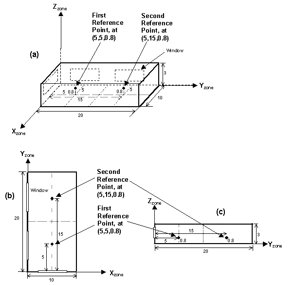
Figure 43. Example showing location of daylighting reference points in the zone coordinate system (relative) of a rectangular zone with three windows. (a) Perspective view, (b) plan view, (c) elevation view. All dimensions are in meters.
The fraction of the zone’s floor-area whose electric lighting is controlled by the daylight illuminance at the First Reference Point. If there is only one reference point then a fraction equal to
1.0 - (Fraction of Zone Controlled by First Reference Point)
is assumed to have no lighting control.
The fraction of the zone’s floor-area whose electric lighting is controlled by the daylight illuminance at the Second Reference Point. Required if Total Daylighting Reference Points = 2. A fraction equal to
1.0 – ([Fraction of Zone Controlled by First Reference Point] + [Fraction of Zone Controlled by Second Reference Point])
is assumed to have no lighting control.
The desired lighting level (in lux) at the First Reference Point. This is the lighting level that would be produced at this reference point at night if the overhead electric lighting were operating at full input power. Recommended values depend on type of activity; they may be found, for example, in the Lighting Handbook of the Illuminating Engineering Society of North America. A typical value for general office work (excluding computer terminals) is 500 lux.
The desired lighting level (in lux) at the Second Reference Point. Required if Total Daylighting Reference Points = 2. This is the lighting level that would be produced at this reference point at night if the overhead electric lighting were operating at full input power.
The type of overhead electric lighting control. All reference points specified are assumed to have this type of control.
For Lighting Control Type = 1 (continuous), the overhead lights dim continuously and linearly from (maximum electric power, maximum light output) to (minimum electric power, minimum light output) as the daylight illuminance increases. The lights stay on at the minimum point with further increase in the daylight illuminance.
For Lighting Control Type = 2 (stepped), the electric power input and light output vary in discrete, equally spaced steps. The number of steps is given by Number of Steps (Excluding Off) of Stepped Control. For example, if Number of Steps = 3 and Illuminance Setpoint = 600, then the following table shows the fraction of the lights that are on vs. daylight illuminance.
Table 18. Stepped Lighting Control Example
|
Example of a Stepped Lighting Control System with Three Steps |
|
|
Daylight illuminance |
Fraction of lights that are on |
|
0-200 |
1.0 |
|
200-400 |
2/3 |
|
400-600 |
1/3 |
|
600 and above |
0.0 |
Lighting Control Type = 3 (continuous/off) is the same as Lighting Control Type = 1 except that the lights switch off completely when the minimum dimming point is reached.
Daylight glare from a window depends on occupant view direction. It is highest when you look directly at a window and decreases as you look away from a window. This field specifies the view direction for calculating glare. It is the angle, measured clockwise in the horizontal plane, between the zone y-axis and the occupant view direction.
If a daylit zone has windows with shading devices (except exterior screens), the shades will be deployed if the daylight glare at the First Reference Point exceeds the value of this field. To get this type of glare control you have to specify Trigger = Glare, GlareOrSolarOnWindow, GlareOrHorizontalSolar, GlareOrOutsideAirTemp, GlareOrZoneAirTemp or GlareOrZoneLoad in WindowProperty:ShadingControl for one or more windows in the zone (see WindowProperty:ShadingControl).
If a zone has two or more windows with glare control, the shading devices will be deployed one by one in the order in which the windows are input until the glare level at each reference point falls below Maximum Allowable Discomfort Glare Index or is as close as possible to it.
The following table gives recommended values of Maximum Allowable Discomfort Glare Index.
Table 19. Recommended Values -- Discomfort Glare Index
|
Recommended Values of Maximum Allowable Discomfort Glare Index |
|
|
Activity or zone type |
Maximum Allowable Discomfort Glare Index |
|
Art Galleries |
16 |
|
Factories |
|
|
Rough work |
28 |
|
Engine assembly |
26 |
|
Fine assembly |
24 |
|
Instrument assembly |
22 |
|
Hospital wards |
18 |
|
Laboratories |
22 |
|
Museums |
20 |
|
Offices |
22 |
|
School classrooms |
20 |
For Lighting Control Type = 1 (continuous), the lowest power the lighting system can dim down to, expressed as a fraction of maximum input power (see figure, below). For Lighting Control Type = 3 (continuous/off) this is the power fraction reached just before the lights switch off completely.

Figure 44. Illustration of continuous dimming relationship
The figure above shows the relationship between electric light output and electrical input.
For Lighting Control Type = 1 (continuous), the lowest lighting output the lighting system can dim down to, expressed as a fraction of maximum light output (see figure, above). This is the fractional light output that the system produces at minimum input power. For Lighting Control Type = 3 (continuous/off) this is the power fraction reached just before the lights switch off completely.
The number of steps, excluding off, in a stepped lighting control system (see figure, below). Required and must be >0 if Lighting Control Type = 2. The steps are assumed to be equally spaced.
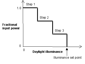
Figure 45. Stepped lighting control with Number of Steps = 3.
May be specified if a stepped lighting control system (Lighting Control Type = 2) is manually operated, such as in a simple, one-step (on-off) system. Gives the probability the occupants of a daylit zone will set the electric lights to the correct level to obtain the required illuminance. The rest of the time the lights are assumed to be set one step too high. For example, consider an on-off lighting system (Number of Steps = 1) with a set point of 600 lux and 0.7 reset probability. Then, when daylighting exceeds 600 lux, the electric lights will be off 70% of the time and on 30% of the time.
An IDF example:
Daylighting:Controls, ! Zone Name
1, ! Total Daylighting Reference Points
3.048,3.048,0.9, ! X,Y,Z coordinates of first reference point {m}
0.0,0.0,0.0, ! X,Y,Z coordinates of second reference point, if present {m}
0.99, ! Fraction of zone controlled by first reference point
0.0, ! Fraction of zone controlled by second reference point, if present
500., ! Illuminance setpoint at first reference point {lux}
500., ! Illuminance setpoint at second reference point, if present {lux}
1, ! Lighting control type {1=continuous,2=stepped,3=continuous/off}
180.0, ! Azimuth angle of view direction for glare calculation {deg},
! measured clockwise from zone y-axis. Value of 180 gives view
! (from reference point) that is directly at window, maximizing glare.
20.0, ! Maximum discomfort glare index for window shade control
0.3, ! Minimum input power fraction for continuous dimming control
0.2, ! Minimum light output fraction for continuous dimming control
0, ! Number of steps, excluding off, for stepped control
1.0; ! Probability electric lighting will be reset when needed (used only
! for stepped control, to simulate manual on/off control)
Following are some guidelines for preparing EnergyPlus input to model the effects of daylighting. Before studying these guidelines, however, you should read the description of each input field under Daylighting:Controls, and review the IDF example, above, and the sample daylighting input, PurchAirWithDaylighting.idf.
If an exterior wall in a daylit zone has a number of identical windows, the windows should be entered separately rather than using a window multiplier (ref: FenestrationSurface:Detailed). Using a multiplier would give an incorrect illuminance calculation since individual windows would not be positioned correctly on the wall.
A zone multiplier should not be used on a daylit zone if the windows in the zone are shadowed by exterior obstructions like trees or neighboring buildings, or by obstructions caused by other parts of building. The reason for this is that the shadowing on the windows of the multiplied zone may be different from zone to zone depending on exactly how the shadows fall on the zones. However, a zone multiplier may be used on a daylit zone if the shadowing is by overhangs, fins and/or window setback.
To correctly calculate both direct and inter-reflected daylight illuminance you should try to model a thermal zone consisting of several similar rooms separated by interior walls as a representative room with a zone multiplier (ref: Zone). An example of this is shown in Figure 46. Room-1 is the representative room, with a zone multiplier = 4.
Interior walls IW-1, IW-2 and IW-3 should be treated as adiabatic, i.e., they should have Outside Boundary Condition = Surface and Outside Boundary Condition Object = IW-1, IW-2, or IW-3, respectively (ref: BuildingSurface:Detailed). Similarly, if the ceiling and floor of Room-1 are interior surfaces, they should be treated as adiabatic.
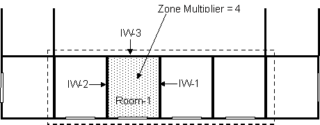
Figure 46. For daylighting purposes the thermal zone enclosed by the dashed boundary line should be modeled as a typical zone (Room-1) with a zone multiplier of 4.
Sometimes a representative room cannot be found. Figure 47 shows a section of a building with four rooms having different daylighting characteristics because of different floor area, orientation and/or window size. In this case lumping the rooms into a single thermal zone would give nonsensical daylighting illuminance values because of the presence of the interior walls, which EnergyPlus ignores when calculating illuminance reaching a reference point directly from a window (i.e., without reflection). The solution in this case is to describe each room as a separate thermal zone with its own daylighting reference points, and input the interior walls because these will participate in the calculation of inter-reflected illuminance.
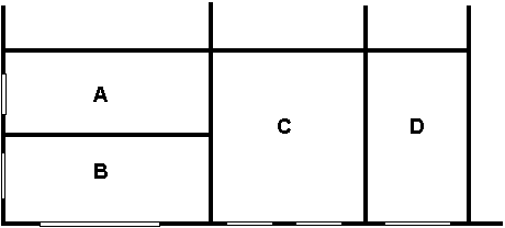
Figure 47. Rooms A, B, C and D have different daylighting characteristics. If lumped into a single thermal zone the daylighting calculation will be less accurate because the blockage of direct light by the interior walls between these rooms is modeled with some simplifications (see Interior Obstructions below). To get a good daylighting calculation each room should be input as a separate thermal zone.
The detailed daylighting calculation allows a thermal zone to be divided into two independently-controlled lighting zones. (See the fields: Fraction of Zone Controlled by First Reference Point, Fraction of Zone Controlled by Second Reference Point, Illuminance SetPoint at First Reference Point, and Illuminance SetPoint at Second Reference Point.) An example is shown in Figure 48, where a relatively deep thermal zone has two lighting zones of equal area.
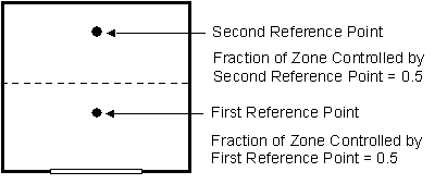
Figure 48. Two independently-controlled lighting zones, each with 50% of the area of the thermal zone.
The daylighting calculation accounts for the presence of exterior obstructions in determining the amount of light that strikes the windows. For daylighting purposes exterior obstructions fall into three categories:
(1) Fins, overhangs, trees, neighboring buildings, etc., entered with the objects Shading:Zone:Detailed,
Shading:Site:Detailed, or
Shading:Building:Detailed.
(2) Building surfaces like walls and roofs (in an L-shaped building, for example).
(3) Surfaces associated with window setback.
Category (1) obstructions can have an associated solar transmittance schedule (see description of the field Transmittance Schedule Name for these shading surfaces). If this schedule is not specified, the surface is opaque (has zero transmittance).
The daylighting calculation takes the transmittance into account in determining, for example, how much light enters a window through a translucent awning. It is assumed that the solar and visible transmittance is the same and that the surfaces are non-diffusing, i.e., they do not change the direction of transmitted light. Ref:Daylighting:Controls.
Category (2) and (3) surfaces are assumed to be opaque.
Surfaces in all three categories are assumed to be black, i.e., they do not reflect light, unless you set if “Reflections” option is chosen in the Building object. Then obstructions can reflect light, such as the top of an overhang reflecting light onto the window above. Ref: Building, Field: Solar Distribution (with reflections options).
The daylighting calculation accounts for the presence of interior obstructions that lie between a window and a reference point. Unlike exterior obstructions, which can be light transmitting, interior obstructions are assumed to be opaque. Interior obstructions can reduce or eliminate the light directly reaching the reference point through a window.
However, interior obstructions that are walls, ceilings or floors are reflecting so they contribute to the inter-reflected component of daylight illuminance as do the non-obstructing zone surfaces.
Interior obstructions can belong to the Shading object series. This type of obstruction is assumed to be non-reflecting so does not contribute to the inter-reflected component of daylight illuminance.
An example of an interior obstruction that is a wall in an L-shaped room is shown in Figure 49. Here, wall A (or, equivalently, Wall B) prevents light from directly getting to the Reference Point from the window.

Figure 49. Wall A (or Wall B) is an interior obstruction that prevents light from directly reaching the daylighting reference point from the window.
The Daylighting:Controls method, with no additional user input, calculates the contribution of daylight that passes into a target zone through interior windows.[7] The origin of this daylight is exterior windows in adjacent zones that share interior windows with the target zone. This capability is aimed at daylighting through a double façade (also called “double envelope” or “double skin.”)
This is illustrated in Figure 50, which shows a double-façade buffer zone, Z0, with exterior windows EW1 and EW2. Z0 shares interior windows IW1, IW2 and IW3 with daylit occupied zones ZD1, ZD2 and ZD3, respectively (“daylit” here means the zone has an associated Daylighting:Controls object). The daylight illuminance at reference points RP1, RP2 and RP3 comes from the interior windows and has two main sources:
1. Daylight that passes through both an exterior window and an interior window in Z0 and reaches a reference point without reflection. This is called “direct illuminance.”
2. Daylight from Z0 that passes through an interior window and reaches a reference point by inter-reflection in the daylit zone. Because the program calculates this source from the interior solar distribution in Z0 it is recommended that the most accurate calculation of this distribution be made, which occurs if Solar Distribution = FullInteriorAndExterior in the Building object.
A third possible source is neglected because it is generally small in double-façade cases. This is daylight that is reflected from the surfaces of Z0, passes through an interior window and then reaches a reference point without inter-reflection in the daylit zone.
PurchAirWithDoubleFacadeDaylighting.idf is an input example of daylighting through an interior window.
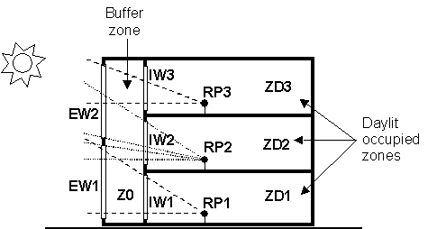
Figure 50. Vertical section through a double-façade building showing daylighting through interior windows. The dashed lines show that (1) reference point RP1 receives direct light from exterior window EW1 via interior window IW1; (2) RP2 receives direct light from EW1 and EW2 via IW2; and (3) RP3 receives direct light from EW2 via IW3.
Figure 51 shows schematically the general configuration of daylighting through interior windows that can be calculated with EnergyPlus. Here, daylit zone ZD has one or more interior windows that are adjacent to other zones, each of which has one or more exterior windows. ZD itself may or may not have exterior windows. If it does, than the daylight illuminance from its exterior and interior windows will be additive. The zones adjacent to ZD may or may not be daylit and may or may not have other interior windows that are not adjacent to ZD. (The program does not consider the illuminance in ZD from electric lighting in adjacent zones.)
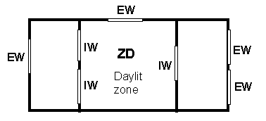
Figure 51. General configuration of daylighting through interior windows that can be calculated with EnergyPlus. IW = interior window, EW = exterior window.
Figure 52 shows schematically a configuration of daylighting through interior windows that cannot be calculated with EnergyPlus. Here, zone Z has an interior window that is adjacent to zone Z1 which in turn has an interior window adjacent to zone Z2. However, the daylight from the exterior window in Z2 that enters Z after passing through Z1 is not calculated because Z2 is not adjacent to Z.
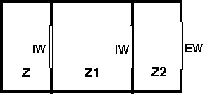
Figure 52. Configuration in which daylighting of zone Z through its interior window cannot be calculated with EnergyPlus. IW = interior window, EW = exterior window.
There are two restrictions on the use of exterior-window shading devices when a daylit zone has interior windows:
1) If two daylit zones share an interior window, neither zone can have an exterior window whose shading device does glare control (i.e., the WindowProperty:ShadingControl for the exterior window has Glare Control Is Active = Yes).
2) If two daylit zones share an interior window, neither zone can have an exterior window with a WindowProperty:ShadingControl that has Shading Control Type = MeetDaylightIlluminanceSetpoint.
The DElight method of analyzing daylighting in buildings is very similar to that used in the Detailed method. For each point in time, DElight calculates the interior daylighting illuminance at specified reference points and then determines how much the electric lighting can be reduced while still achieving a combined daylighting and electric lighting illuminance target. The daylight illuminance level in a zone depends on many factors, including exterior light sources; location, size, and visible light transmittance of simple and complex fenestration systems; reflectance of interior surfaces; and location of calculation reference points. The subsequent reduction of electric lighting depends on daylight illuminance level, illuminance set point, fraction of zone controlled, and type of lighting control.
There are two primary differences between the Detailed and DElight methods of calculating interior illuminance levels. The first is that DElight includes the capability of analyzing complex fenestration systems that include geometrically complicated shading systems (e.g., roof monitors) and/or optically complicated glazings (e.g., prismatic or holographic glass). The second key difference is that DElight uses a radiosity method to calculate the effects of light reflection inside a zone. These methods are discussed in more detail in the engineering documentation.
There are other important differences between the two methods. One is the inability of DElight to perform the type of dynamic shading controls possible using the Detailed method at each point in time during the thermal simulation (e.g., changes in electrochromic glazing transmittances and blind slat angles). Another is the DElight ability to include more than two reference points in its interior illuminance and electric lighting reduction calculations. A third is the current lack of visual quality (e.g., glare) calculations performed by DElight. Fourth, the modeling of interior obstructions is different in the two methods. In the DElight method interior obstructions block interreflections but do not block the intial direct illuminance. In the Detailed method, interior obstructions block the initial direct illuminance but do not block interreflections. See the engineering documentation for more details.
Input for invoking the DElight method involves three object types: Daylighting:DELight:Controls, Daylighting:DELight:ReferencePoint, and Daylighting:DELight:ComplexFenestration. Each of these objects is described below.
The first input object required for invoking the DElight method is the Daylighting:DELight:Controls object, which defines the parameters of each daylighting zone within a building. This object must be associated with a specific thermal zone within the building for which the reduction in electric lighting due to daylight illuminance will be accounted.
User name of the DElight daylighting zone to which the following input applies.
The name of the thermal Zone hosting this DElight daylighting zone. This must be a valid name that has been associated with a thermal Zone contained in the same EnergyPlus input data file.
The type of overhead electric lighting control. All reference points specified are assumed to have this type of control.
For Lighting Control Type = 1 (continuous), the overhead lights dim continuously and linearly from (maximum electric power, maximum light output) to (minimum electric power, minimum light output) as the daylight illuminance increases. The lights stay on at the minimum point with further increase in the daylight illuminance.
For Lighting Control Type = 2 (stepped), the electric power input and light output vary in discrete, equally spaced steps. The number of steps is given by Number of Steps (Excluding Off) of Stepped Control. For example, if Number of Steps = 3 and Illuminance Setpoint = 600, then the following table shows the fraction of the lights that are on vs. daylight illuminance.
Table 20. Stepped Lighting Control Example
|
Example of a Stepped Lighting Control System with Three Steps |
|
|
Daylight illuminance |
Fraction of lights that are on |
|
0-200 |
1.0 |
|
200-400 |
2/3 |
|
400-600 |
1/3 |
|
600 and above |
0.0 |
Lighting Control Type = 3 (continuous/off) is the same as Lighting Control Type = 1 except that the lights switch off completely when the minimum dimming point is reached.
For Lighting Control Type = 1 (continuous), the lowest power the lighting system can dim down to, expressed as a fraction of maximum input power (see figure, below). For Lighting Control Type = 3 (continuous/off) this is the power fraction reached just before the lights switch off completely.
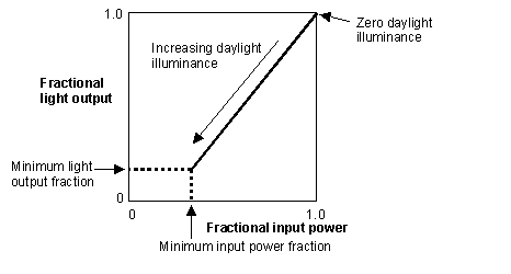
Figure 53. Illustration of continuous dimming relationship
The figure above shows the relationship between electric light output and electrical input.
For Lighting Control Type = 1 (continuous), the lowest lighting output the lighting system can dim down to, expressed as a fraction of maximum light output (see figure, above). This is the fractional light output that the system produces at minimum input power. For Lighting Control Type = 3 (continuous/off) this is the power fraction reached just before the lights switch off completely.
The number of steps, excluding off, in a stepped lighting control system (see figure, below). Required and must be >0 if Lighting Control Type = 2. The steps are assumed to be equally spaced.
Figure 54. Stepped lighting control with Number of Steps = 3.
May be specified if a stepped lighting control system (Lighting Control Type = 2) is manually operated, such as in a simple, one-step (on-off) system. Gives the probability the occupants of a daylit zone will set the electric lights to the correct level to obtain the required illuminance. The rest of the time the lights are assumed to be set one step too high. For example, consider an on-off lighting system (Number of Steps = 1) with a set point of 600 lux and 0.7 reset probability. Then, when daylighting exceeds 600 lux, the electric lights will be off 70% of the time and on 30% of the time.
The maximum surface area for nodes in gridding (subdividing) all surfaces in the DElight zone. All reflective and transmitting surfaces will be subdivided into approximately square nodes that do not exceed this maximum. Higher resolution subdivisions require greater calculation times, but generally produce more accurate results. This same gridding resolution is also used to subdivide any Complex Fenestration System surfaces. It is advisable to perform at least one simulation of new input using a small gridding resolution such as 0.1m2 to compare these results against simulation runs at lower resolution (i.e., higher maximum area nodal grids) to get a sense of possible levels of error.
An IDF example:
Daylighting:DELight:Controls,
DElight NORTH ZONE, !- DElight Zone Name
NORTH ZONE, !- Zone Name
1, !- Lighting control type
0.3, !- Minimum input power fraction for continuous dimming control
0.2, !- Minimum light output fraction for continuous dimming control
0, !- Number of steps (excluding off) for stepped control
1.0, !- Probability lighting will be reset when needed in manual stepped control
1.0; !- Gridding Resolution {m2}
The second input object required for invoking the DElight method is the Daylighting:DELight:ReferencePoint object, which defines the parameters of each Reference Point within the associated DElight daylighting zone. This object must be associated with a specific Daylighting:DELight:Controls object instance. There may be up to a maximum of 100 Reference Points for each DElight daylighting zone. Each Reference Point that is input does NOT need to be included in the control of the electric lighting system within the zone. This is determined by the fraction of the zone controlled by each Reference Point, which can be input as 0. Note that the sum of all Reference Point control fractions must equal 1 to obtain correct overall results.
User name of the DElight daylighting Reference Point to which the following input applies.
The name of the Daylighting:DELight:Controls object instance hosting this Reference Point. This must be a valid name that has been associated with a DElight daylighting Zone contained in the same EnergyPlus input data file.
These three fields are the X, Y and Z values of the Reference point in the coordinate system you specified for daylighting reference points in the GlobalGeometryRules object. Figure 55 shows an example using the relative coordinate (to zone) system. Z is typically at work surface height (e.g., 0.8m for a desk).

Figure 55. Example showing location of two daylighting reference points in the zone coordinate system (relative) of a rectangular zone with three windows. (a) Perspective view, (b) plan view, (c) elevation view. All dimensions are in meters.
The zone floor-area fraction of the electric lighting that is controlled by the daylight illuminance at this Reference Point. If the sum of the values for this field for all Reference Points input for a given daylighting zone is less than 1.0, then the remaining fraction (i.e., 1.0 – Sum) is assumed to not have lighting control.
Note that Reference Points may be input with a 0.0 value for this fraction. In this case, daylight factors and interior illuminance values will be calculated for the Reference Point, but it will play no role in controlling the electric lighting within the daylighting zone to which it belongs.
The desired lighting level (in lux) at this Reference Point. This is assumed to be the lighting level that would be produced at this reference point at night if the overhead electric lighting were operating at full input power. Recommended values depend on the type of activity and may be found, for example, in the Lighting Handbook of the Illuminating Engineering Society of North America. A typical value for general office work (excluding computer terminals) is 500 lux.
An IDF example:
Daylighting:DELight:ReferencePoint,
RefPt 2, !- Reference Point Name
DElight NORTH ZONE, !- DElight Zone Name
5.0, !- X-coordinate of reference point {m}
3.0, !- Y-coordinate of reference point {m}
0.9, !- Z-coordinate of reference point {m}
0.5, !- Fraction of zone controlled by reference point
500.; !- Illuminance setpoint at reference point {lux}
The third input object related to the DElight method is the Daylighting:DElight: Complex Fenestration object. The DElight daylighting analysis method can be applied to daylighting zones that contain only simple fenestration systems such as windows and skylights that are standard EnergyPlus sub-surfaces. In this situation, no Daylighting:DElight: Complex Fenestration object would be input.
In addition to analyzing simple fenestration systems, DElight includes the capability of analyzing complex fenestration systems such as geometrically complicated static shading systems (e.g., roof monitors) and/or optically complicated glazings (e.g., prismatic or holographic glass). This capability is based on characterizing these complex fenestration systems (CFS) using bi-directional transmittance distribution functions (BTDF). In general, BTDF data for a specific CFS must be either measured or simulated (e.g., using ray-tracing techniques) prior to employing DElight to analyze it within EnergyPlus. The current implementation of DElight CFS calculations within EnergyPlus supports two approaches to the input of BTDF, an analytical approach and a file-based approach. The details of inputting these two approaches are described below under the User Complex Fenestration Type field.
Two analytical CFS BTDF types are currently supported, window and light shelf. The file-based approach requires that a user has access to a data file containing raw BTDF data that DElight reads as additional input during its analysis calculations. BTDF data files are described separately since it is anticipated that individual EnergyPlus users will not create these data files themselves.
The methods related to characterizing and analyzing CFS using BTDF are still evolving. DElight is an early implementation of CFS analysis methods. These methods, and the input associated with them here, will likely change in the future.
User name of the DElight daylighting Complex Fenestration to which the following input applies.
Type name of the DElight daylighting Complex Fenestration system to be analyzed. This type name must take one of the following two forms.
BTDF^GEN^Analytical Type^Normal Visible Transmittance^Dispersion Angle
BTDF^FILE^Filename
The first form above is for supported analytical CFS types which currently include WINDOW and LIGHTSHELF. While these analytical types are relatively simple, they represent flexible ways to explore diffusing CFS systems and the impact of light shelves in redirecting light through an aperture. Each of these types also requires the visible transmittance of the CFS at normal incidence angle, and a dispersion angle (in degrees) that represents the “spread” of transmitted light. A small dispersion angle of 10 corresponds to clear glazing while a large angle of 90 corresponds to perfectly diffusing glazing. The “^” symbol must be used as a delimiter between sub-fields within this Complex Fenestration type name string as shown in the IDF example for WINDOW below, and in the DElight sample input data files.
The second form above is for CFS types for which there is pre-measured or pre-simulated BTDF data. In this case the Filename sub-field must be a valid data file name that is associated with an existing BTDF dataset that DElight can use in its calculations.
The name of the heat transfer surface object instance hosting this Complex Fenestration, analogous to the Building Surface Name field for subsurfaces such as Windows. This must be a valid name that has been associated with a heat transfer surface contained in the same EnergyPlus input data file.
The name of the Window (ref: FenestrationSurface:Detailed object) instance that will be used to account for the geometry, and the solar/thermal gains/losses, of the Complex Fenestration system surface. This must be a valid name that has been associated with a Window contained in the same EnergyPlus input data file. The geometry for the Complex Fenestration is taken from the geometry input for this standard EnergyPlus subsurface, hence the term “Doppelganger.”
Note that DElight only deals with the visible spectrum of light transmitted through a Complex Fenestration. To account for the solar/thermal influences of a Complex Fenestration, a geometrically coincident subsurface that will be accounted for by methods already within EnergyPlus must be defined in the input data file. This is an interim solution to the issue of accounting for solar/thermal influences that will likely change as techniques analogous to the daylighting analysis of BTDF are developed.
The in-plane counter-clockwise rotation angle between the Complex Fenestration optical reference direction and the base edge of the Doppelganger Surface geometry. The Complex Fenestration optical reference direction is the direction of the zero azimuth angle for the BDTF dataset. This Rotation angle will typically be zero when the Doppelganger surface is rectangular and its width edge is aligned with the Complex Fenestration optical reference direction.
An IDF example for an analytical WINDOW type CFS:
Daylighting:DELight:ComplexFenestration,
Window CFS, !- DElight Complex Fenestration User Name
BTDF^GEN^WINDOW^1.0^20.0, !- Complex Fenestration Type
ZN003:WALL001, !- Complex Fenestration Host Surface
Zn003:Wall001:Doppel001, !- Doppelganger Surface Name
0.0; !- Fenestration Rotation {degrees}
In addition to the daylighting-specific outputs for DElight listed below, two ASCII text files are created during an EnergyPlus run that includes DElight analysis. Following completion of an EnergyPlus run, these files are given names that consist of the project name appended with DElight.in and DElight.out. The format of these files is described in the Output Details and Examples document.
The following daylighting-specific outputs are available for Daylighting:DELight:Controls within the standard EnergyPlus output environment:
Zone,Average,DElight Reference Point Daylight Illuminance [lux]
Zone,Average,Ltg Power Multiplier from Daylighting []
The total daylight illuminance at a DElight reference point from all of the exterior windows in a daylit zone.
The amount by which the overhead electric lighting power in a zone is multiplied due to usage of DElight calculated daylighting to dim or switch electric lights. For example, if the multiplier is M and the electric power without dimming is P, then the electric power with dimming is M*P. The multiplier varies from 0.0, which corresponds to maximum dimming (zero electric lighting), to 1.0, which corresponds to no dimming.
The following daylighting-specific outputs are available for Daylighting:Controls:
Zone,Average,Exterior Beam Normal Illuminance [lux]
Zone,Average,Exterior Horizontal Beam Illuminance [lux]
Zone,Average,Exterior Horizontal Illuminance From Sky [lux]
Zone,Average,Luminous Efficacy of Beam Solar Radiation [lum/W]
Zone,Average,Luminous Efficacy of Sky Diffuse Solar Radiation [lum/W]
Zone,Average,Sky Clearness for Daylighting Calculation []
Zone,Average,Sky Brightness for Daylighting Calculation []
Surface,Average,Daylight Luminance of Window As Viewed From Ref Point 1 [cd/m2]
Surface,Average,Daylight Illum at Ref Point 1 from Window [lux]
Zone,Average,Daylight Illum at Ref Point 1 [lux]
Zone,Average,Glare Index at Ref Point 1 []
Zone,Sum,Time Exceeding Glare Index Setpoint at Ref Point 1 [hr]
Zone,Sum,Time Exceeding Daylight Illuminance Setpoint at Ref Point 1 [hr]
Surface,Average,Daylight Luminance of Window As Viewed From Ref Point 2 [cd/m2]
Surface,Average,Daylight Illum at Ref Point 2 from Window [lux]
Zone,Average,Daylight Illum at Ref Point 2 [lux], if applicable
Zone,Average,Glare Index at Ref Point 2 [], if applicable
Zone,Sum,Time Exceeding Glare Index Setpoint at Ref Point 2 [hr]
Zone,Sum,Time Exceeding Daylight Illuminance Setpoint at Ref Point 2 [hr]
Zone,Average,Ltg Power Multiplier from Daylighting []
Beam normal illuminance of the sun at the earth’s surface, measured in lux (lumens/m2)
Beam illuminance on an unobstructed horizontal plane at the earth’s surface. Equals “Exterior Beam Normal Illuminance” times sine of solar altitude.
Illuminance from sky solar radiation on an unobstructed horizontal plane at the earth’s surface. The total exterior horizontal illuminance is the sum of “Exterior Horizontal Beam Illuminance” and “Exterior Horizontal Illuminance From Sky.”
A measure of the visible light content of beam solar radiation; equal to the number of lumens per watt of beam solar radiation. Depends on atmospheric conditions (moisture, turbidity, cloudiness) and solar altitude.
A measure of the visible light content of sky diffuse solar radiation; equal to the number of lumens per watt of sky diffuse solar radiation. Depends on atmospheric conditions (moisture, turbidity, cloudiness) and solar altitude.
Clearness of sky. One of the factors used to determine sky type and luminous efficacy of solar radiation (see EnergyPlus Engineering Document). Sky Clearness close to 1.0 corresponds to an overcast sky. Sky Clearness > 6 is a clear sky.
Brightness of sky. One of the factors used to determine sky type and luminous efficacy of solar radiation (see EnergyPlus Engineering Document).
The area-averaged luminance of an exterior window as viewed from the first reference point in the daylit zone containing the window. In general, higher window luminance values are associated with higher daylight glare values. (Printed only for exterior windows in daylit zones without interior windows.)
The contribution from a particular exterior window to the daylight illuminance at the first reference point in the daylit zone containing the window. (Not printed for exterior windows in daylit zones with interior windows.)
The total daylight illuminance at the first reference point from all of the exterior windows in a daylit zone.
The daylight glare index at the first reference point in a daylit zone.
The number of hours when the calculated daylight glare index at the first reference point exceeds the glare index setpoint.
The number of hours when the calculated daylight illuminance at the first reference point exceeds the daylight illuminance setpoint.
The area-averaged luminance of an exterior window as viewed from the second reference point, if present, in the daylit zone containing the window. Note that, for a bare window, this value can be different from the corresponding value at the first reference point since different regions of the sky and ground will be visible from the two reference points, and different ranges of angles of incidence and associated glass transmittance values will be involved. (Not printed for exterior windows in daylit zones with interior windows.)
The contribution from a particular exterior window to the daylight illuminance at the second reference point, if present, in the daylit zone containing the window. (Not printed for exterior windows in daylit zones with interior windows.)
The daylight glare index at the second reference point, if present, in a daylit zone.
The number of hours when the calculated daylight glare index at the second reference point exceeds the glare index setpoint.
The number of hours when the calculated daylight illuminance at the second reference point exceeds the daylight illuminance setpoint.
The amount by which the overhead electric lighting power in a zone is multiplied due to usage of daylighting to dim or switch electric lights. For example, if the multiplier is M and the electric power without dimming is P, then the electric power with dimming is M*P. The multiplier varies from 0.0, which corresponds to maximum dimming (zero electric lighting), to 1.0, which corresponds to no dimming.
The Output:IlluminanceMap object expands on the reporting capabilities of the daylighting simulation. For any zone simulated with Daylighting:Controls, the illuminance map can generate up to 2,500 points of additional daylighting illuminance values. The resulting map is output as a comma delimited text file that can be imported into a spreadsheet program for rapid visualization of the daylighting illuminance patterns in a zone. The values are produced on an hourly basis. The Z height of the map is constant (parallel to a flat floor). More than one illuminance map can be created for a zone.
The name of the map object.
Reference to a zone with Daylighting:Controls.
The height or elevation of the grid of daylighting points.
The minimum X coordinate boundary for the map.
The maximum X coordinate boundary for the map.
The number of daylighting reference points in the X direction from the minimum to the maximum boundaries. The maximum number of points that can be generated is 2500 (Number of X Grid Points X Number of Y Grid Points).
The minimum Y coordinate boundary for the map.
The maximum Y coordinate boundary for the map.
The number of daylighting reference points in the Y direction from the minimum to the maximum boundaries. The maximum number of points that can be generated is 2500 (Number of X Grid Points X Number of Y Grid Points).
Note: Daylighting factors cannot be accurately calculated for reference points that are very close to a wall or window (less than 0.15 m or 6 inches). An error is reported for a reference point that is too close to a window, but no error is reported for a point that is too close to a wall.
Output:IlluminanceMap,
Daylit Map, ! Map Name
Daylit Zone, ! Zone Name
0, ! Z Height [m]
0.1, ! X Minimum Coordinate [m]
4.9, ! X Maximum Coordinate [m]
10, ! Number of X Grid Points
0.1, ! Y Minimum Coordinate [m]
9.9, ! Y Maximum Coordinate [m]
10; ! Number of Y grid Points
Since not all zones are rectangular, it is possible to have map points that are outside the zone. Any illuminance registered at these points is inaccurate and, additionally, a “*” marks these values for easy observance.
This object specifies the “style” for the illuminance map output (described in the Output Details and Examples document). As described above (see: EnergyPlus Output Processing), the user may select the “style” for the daylighting illuminance map output file (eplusmap.<ext>).
For this field, the desired separator for columns is entered. “Comma” creates comma separated fields/columns in the outputs (eplusmap.csv file is created). “Tab” creates tab separated fields/columns in the outputs (eplusmap.tab file is created). “Fixed” creates space separated fields/columns in the outputs (eplusmap.txt file is created) but these are not necessarily lined up for easy printing.
Note that both tab and comma separated files easily import into Excel™ or other spreadsheet programs. The tab delimited files can also be viewed by text editors, word processing programs and easily converted to “tables” within those programs.
Daylighting devices work in conjunction with the Daylighting:Controls object to simulate components that can improve daylighting in a zone.
Daylighting devices are also tightly integrated into the zone heat balance. The thermal effects of these devices are simulated with or without the use of a Daylighting:Controls object.
There are two types of daylighting device in EnergyPlus: tubular daylighting devices and daylighting shelves.
Tubular daylighting devices (TDDs), also known as tubular skylights or light pipes, are used to bring natural exterior daylight into the hard-to-reach, interior spaces of a building.
TDDs consist of three components: a dome, a pipe, and a diffuser.
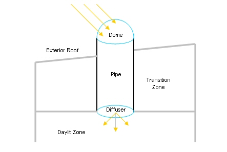
Figure 56. Tubular daylighting device diagram.
In EnergyPlus each of these components corresponds to an object in the input file.
The dome and diffuser are defined in the same way as windows using the FenestrationSurface:Detailed object. The Surface Type field must be specified as TubularDaylightDome or TubularDaylightDiffuser accordingly.
The location and orientation of the dome surface affect the total amount of daylight collected.
The Base Surface of the diffuser object determines to which zone the daylighting is delivered. The location and orientation of the diffuser surface affect the amount of daylight received at the Daylighting:Controls reference points.
Although the object definition is the same as for a window, there are several restrictions on TubularDaylightDome and TubularDaylightDiffuser objects:
n Shading control devices are not allowed.
n Frames and dividers are not allowed.
n Multipliers must be 1.0.
n Dome, diffuser, and pipe areas (as given by diameter) must be approximately equal.
n Outside face environment objects are not allowed.
n Dome and diffuser constructions cannot be more than one layer.
Since commercial TDDs are assumed to be cylindrical in shape, it is recommended that the circular areas of the actual dome and diffuser be approximated with a square of equivalent area for the TubularDaylightDome and TubularDaylightDiffuser objects. Although it is possible to use a triangular surface instead, a square is a much better geometric approximation of a circle.
Note that the TubularDaylightDome surface is allowed to have a different position and tilt from the roof base surface. If the actual TDD projects some height above the roof surface, the TubularDaylightDome coordinates should be located accordingly.
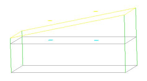
Figure 57. Tubular daylighting device DXF output.
The TubularDaylightDome surface automatically casts a shadow on the roof base surface. However, since the pipe is not represented by a surface, it will not cast a shadow. If this effect must be simulated, one or more SURFACE:SHADING objects can be used.
The dome and diffuser objects are connected by the DAYLIGHTING DEVICE:TUBULAR object:
The name of the TDD object.
Reference to a FenestrationSurface:Detailed object with Surface Type TubularDaylightDome.
Reference to a FenestrationSurface:Detailed object with Surface Type TubularDaylightDiffuser.
The construction of the TDD pipe. The visible and solar absorptance of the inside material layer determines the reflectivity of the inner mirrored surface of the TDD. This is very important for the overall transmittance of the TDD.
The diameter [m] of the TDD pipe. The area of the pipe must match the areas of the dome and diffuser.
The total length [m] of the TDD pipe between the dome and the diffuser, including the exterior part above the roof. The exterior length is determined internally by subtracting the transition zone lengths from the total length.
The effective thermal resistance [m2-K/W], i.e. R-value, of the TDD between the exterior dome surface and the interior diffuser surface.
Name of zone that the TDD pipe passes through before reaching the delivery zone.
Length of pipe [m] in the transition zone. This is used for determining heat gains due to solar absorbed by the pipe in each transition zone. The distribution of absorbed solar gains can be customized by adjusting the length of pipe in each transition zone. The transition zone gain is proportional to the length of pipe in the zone. If no transition zones are specified, all solar absorbed by the pipe is lost to the exterior environment.
The Transition Zone Name and Transition Zone Length fields can be repeated for additional transition zones.
DaylightingDevice:Tubular,
Pipe1, !- Object Name
Dome1, !- Dome Name
Diffuser1, !- Diffuser Name
Reflective Aluminum, !- Construction Name
0.3556, !- Diameter [m] (approximately 14", a standard size)
1.4, !- Total Length [m] (subtract zone lengths to get outdoor exposed length)
0.28, !- Effective Thermal Resistance [m2-K/W] between TubularDaylightDome and
! TubularDaylightDiffuser
Attic Zone, !- Transition Zone 1 Name
1.1; !- Transition Zone 1 Length [m]
FenestrationSurface:Detailed,
Dome1, !- Subsurface Name
TubularDaylightDome, !- Surface Type
Clear Acrylic Dome, !- Construction Name (only 1 layer allowed in construction)
Attic Roof, !- Base Surface Name
, !- Outside Face Environment (not allowed for TubularDaylightDome)
0.0, !- VF to Ground
, !- Window Shading Control (not allowed for TubularDaylightDome)
, !- Frame/Divider Name (not allowed for TubularDaylightDome)
1.0, !- Multiplier (must be 1.0 for TubularDaylightDome)
4, !- Number of Vertices
2.3425, 3.1575, 3.9,
2.3425, 2.8425, 3.9,
2.6575, 2.8425, 3.9,
2.6575, 3.1575, 3.9;
FenestrationSurface:Detailed,
Diffuser1, !- Subsurface Name
TubularDaylightDiffuser, !- Surface Type
Frosted Acrylic Diffuser, !- Construction Name (only 1 layer allowed in construction)
Daylit Zone Ceiling, !- Base Surface Name
, !- Outside Face Environment (not allowed for TubularDaylightDiffuser)
0.0, !- VF to Ground
, !- Window Shading Control (not allowed for TubularDaylightDiffuser)
, !- Frame/Divider Name (not allowed for TubularDaylightDiffuser)
1.0, !- Multiplier (must be 1.0 for TubularDaylightDiffuser)
4, !- Number of Vertices
2.3425, 3.1575, 2.5,
2.3425, 2.8425, 2.5,
2.6575, 2.8425, 2.5,
2.6575, 3.1575, 2.5;
The following output variables are specific to the DaylightingDevice:Tubular object:
Zone,Average,TDD Transmitted Solar [W]
Zone,Average,TDD Pipe Absorbed Solar [W]
Zone,Average,TDD Heat Gain [W]
Zone,Average,TDD Heat Loss [W]
Zone,Average,TDD Beam Solar Transmittance []
Zone,Average,TDD Beam Visible Transmittance []
Zone,Average,TDD Diffuse Solar Transmittance []
Zone,Average,TDD Diffuse Visible Transmittance []
In addition, several surface and window variables are also reported for the TubularDaylightDome and TubularDaylightDiffuser objects. For the TubularDaylightDome:
Zone,Average,Surface Ext Sunlit Area [m2]
Zone,Average,Surface Ext Sunlit Fraction []
Zone,Average,Surface Ext Solar Incident[W/m2]
Zone,Average,Surface Ext Solar Beam Incident[W/m2]
Zone,Average,Surface Ext Solar Sky Diffuse Incident[W/m2]
Zone,Average,Surface Ext Solar Ground Diffuse Incident[W/m2]
Zone,Average,Surface Ext Solar Beam Cosine Of Incidence Angle[]
Zone,Average,Window Transmitted Solar[W]
Zone,Average,Window Solar Absorbed:All Glass Layers[W]
For the TubularDaylightDiffuser:
Zone,Average,Surface Ext Solar Incident[W/m2] (incident inside of pipe)
Zone,Average,Window Transmitted Solar[W] (same as TDD Transmitted Solar)
Zone,Average,Window Solar Absorbed:All Glass Layers[W]
Daylighting shelves, or simply light shelves, are another device for bringing more daylight into a building. Installed as an accessory to a window, daylighting shelves work by reflecting exterior light onto the ceiling of a room. Daylighting shelves can have an inside shelf, an outside shelf, or both.
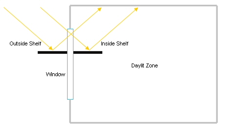
Figure 58. Daylighting shelf diagram.
The inside shelf redistributes light that would have entered the zone anyway. Instead of entering as a beam, all light is reflected onto the zone ceiling and is converted to diffuse shortwave radiation.
The outside shelf changes the amount of light entering the zone. If the shelf surface is more reflective than the ground, it can increase the amount of light incident on the upper part of the window. However, the shading effect of the outside shelf on the lower part of the window must also be considered as it can easily negate any gain achieved in the upper part of the window. All light reflected from the outside shelf that enters the upper window is assumed to strike the ceiling.
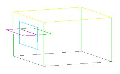
Figure 59. Daylighting shelf DXF output.
In EnergyPlus a daylighting shelf is simulated using a DaylightingDevice:Shelf object in combination with up to three other objects: a window, a heat transfer surface, and an attached shading surface.
The window must be divided into two window surfaces: an upper window and a lower window. The upper window interacts directly with the daylighting shelf object and is not allowed to have any shading control devices or frames or dividers. The lower window does not interact with the daylighting shelf object, but does receive shading from the outside shelf. There are no restrictions on the lower window.
The inside shelf is defined as a regular heat transfer surface in the zone. However, the surface must have the Outside Boundary Condition field set to Surface with itself as the other zone surface. Shading and thermal mass effects are taken into account.
The outside shelf is defined as a Shading:Zone:Detailed object. The visible and solar absorptance of the outside material layer determines the reflectivity of the shelf.
NOTE: Unlike a regular Shading:Zone:Detailed object, the vertices of the outside shelf surface must be ordered so that the outward normal vector points upward, i.e. toward the upper window. This is necessary in order for the outside shelf to properly receive sunlight and shading from other surfaces. A mirror shading surface with the outward normal vector pointing in the opposite direction is automatically created by the program to shade the lower window.
The inside shelf and outside shelf are both optional. However, if neither shelf is specified, the daylighting shelf object has no effect on the simulation.
The name of the daylighting shelf object.
Reference to a FenestrationSurface:Detailed object with Surface Type WINDOW.
Reference to a BuildingSurface:Detailed object. This field is optional. If used, this surface must have OTHERZONESURFACE specified for the Outside Face Environment field and the referenced other zone surface must be itself. The number of vertices of this surface object must be 4.
Reference to a Shading:Zone:Detailed object. This field is optional. If used, the number of vertices of this surface object must be 4.
Reference to a CONSTRUCTION object. This field is required if an outside shelf is specified. The visible and solar absorptance of the outside material layer determines the shelf reflectivity.
User defined value for the view factor from the window to the outside shelf. This field is optional. If not specified, an exact view factor is calculated for two perpendicular rectangles of the same width having a shared edge. If the given surfaces do not meet these geometric requirements, it is necessary to specify a value here.
NOTE: It is up to the user to adjust the view factor to ground of the upper window to account for the part of the view blocked by the outside shelf. The calculated View Factor To Outside Shelf is reported in the eio file for this purpose. For the typical case where the shelf is parallel to the ground and the upper window is perpendicular to the ground, the view factor to ground is simply: 0.5 – View Factor To Outside Shelf.
DaylightingDevice:Shelf,
Shelf, !- Name
Daylit Upper Window, !- Window Name
Inside Shelf, !- Inside Shelf Name
Outside Shelf, !- Outside Shelf Name
Shelf Construction; !- Outside Shelf Construction Name (required if outside shelf specified)
! 0.29; !- View Factor To Outside Shelf (optional)
FenestrationSurface:Detailed,
Daylit Upper Window, !- Subsurface Name
Window, !- Surface Type
Standard Window, !- Construction Name
Daylit South Wall, !- Base Surface Name
, !- Outside Face Environment
0.211, !- VF to Ground (user must adjust to account for view factor to outside shelf)
, !- Window Shading Control (not allowed)
, !- Frame/Divider Name (not allowed)
1.0, !- Multiplier (must be 1.0)
4, !- Number of Vertices
1.0, 0.0, 2.8,
1.0, 0.0, 2.0,
4.0, 0.0, 2.0,
4.0, 0.0, 2.8;
BuildingSurface:Detailed,
Inside Shelf, !- Surface Name
Wall, !- Surface Type
Shelf Construction, !- Construction Name
Daylit Zone, !- Zone Name
OtherZoneSurface, !- Exterior Conditions (must be OtherZoneSurface)
Inside Shelf, !- Target (must be itself)
NoSun, !- Solar Exposure
NoWind, !- Wind Exposure
0.0, !- VF to Ground
4, !- Number of Vertices
1.0, 0.0, 2.0,
4.0, 0.0, 2.0,
4.0, 1.0, 2.0,
1.0, 1.0, 2.0;
Shading:Zone:Detailed,
Outside Shelf, !- Surface Name
Daylit South Wall, !- Base Surface Name
, !- Shading Transmittance Schedule (default is always opaque)
4, !- Number of Vertices
1.0, 0.0, 2.0, !- Outward normal vector must point up toward the upper window
1.0, -1.0, 2.0,
4.0, -1.0, 2.0,
4.0, 0.0, 2.0;
The view factor to outside shelf calculation shows up in the .eio file along with the associated window and window view factors to sky and ground:
! <Shelf Details>,Name,View Factor to Outside Shelf,Window Name,Window View Factor to Sky,Window View Factor to Ground
SHELF,0.29,DAYLIT UPPER WINDOW,0.50,0.21
This variable reports the calculated View Factor To Outside Shelf so that the user can correctly adjust the view factor to ground of the upper window.
The usual window and surface variables are relevant for the upper window:
Zone,Average,Surface Ext Sunlit Area [m2]
Zone,Average,Surface Ext Sunlit Fraction []
Zone,Average,Surface Ext Solar Incident[W/m2]
Zone,Average,Surface Ext Solar Beam Incident[W/m2]
Zone,Average,Surface Ext Solar Sky Diffuse Incident[W/m2]
Zone,Average,Surface Ext Solar Ground Diffuse Incident[W/m2]
Zone,Average,Surface Ext Solar Beam Cosine Of Incidence Angle[]
Zone,Average,Window Transmitted Solar[W]
Zone,Average,Window Solar Absorbed:All Glass Layers[W]
Zone,Average,Window Heat Gain[W]
Zone,Average,Window Heat Loss[W]
The following surface variables are reported for the outside shelf surface, if specified:
Zone,Average,Surface Ext Sunlit Area [m2]
Zone,Average,Surface Ext Sunlit Fraction []
Zone,Average,Surface Ext Solar Incident[W/m2]
Zone,Average,Surface Ext Solar Beam Incident[W/m2]
Zone,Average,Surface Ext Solar Sky Diffuse Incident[W/m2]
Zone,Average,Surface Ext Solar Ground Diffuse Incident[W/m2]
Zone,Average,Surface Ext Solar Beam Cosine Of Incidence Angle[]
This object is used to model the impacts on daylighting of a “light well” that might be associated with exterior windows such as skylights. The light well model attenuates the light transmitted by the skylight. The attenuation is characterized by the well efficiency, which is the ratio of the amount of light leaving the well to the amount of light entering the well. The well efficiency varies from close to 1.0 to close to zero if there is high attenuation. The well efficiency is used only in the EnergyPlus detailed daylighting calculation, where it multiplies the beam and diffuse light transmitted by the skylight. (The well efficiency is not used in calculating the solar gain through the skylight.)
The input object describes the light well using basic characteristics of the geometry along with the visible reflectance of the well’s side walls. The following figure diagrams how the geometry is characterized.
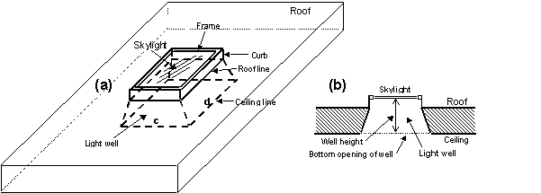
Figure 60. Skylight with light well: (a) perspective view, (b) vertical section.
If the bottom of the light well is a rectangle of side lengths c and d, as shown in (a), then the perimeter of the bottom of the well = 2(c+d) and the area = cd (see description of field names for the Light Well object).
The name of the exterior window that this Light Well is associated with. Generally this is a skylight in a roof. However, light wells can be applied to an exterior window of any slope. Light wells can be assigned to both rectangular and triangular exterior windows, but they should not be assigned to interior windows. Note that the sides of the light well can be sloped and the bottom of the light well can be any shape, not just rectangular.
The distance from the bottom of the skylight to the bottom of the well. If the skylight and well bottom are not coplanar, this is the distance from the center of the bottom of the skylight to center of the bottom of the well. See Figure 60.
The perimeter of the bottom opening of the well. See Figure 60.
The area of the bottom opening of the well. A warning will be issued if this area is less that the area of the skylight, including frame if present. See Figure 60.
The visible reflectance of the side walls of the well. If the walls do not all have the same reflectance, an area-weighted average value can be used. This is the well-wall reflectance expressed as a fraction.
An IDF example:
DaylightingDevice:LightWell, ! The well is 60% reflecting, is 1.2m high and has a 2.5m x 5.5m bottom opening.
Skylight-1, !- Name of Exterior Window that this Light Well Applies To
1.2, !- Height of Well(m)
16.0, !- Perimeter of Bottom of Well (m)
13.75, !- Area of Bottom of Well (m2)
0.60; !- Visible Reflectance of Well Walls
The following table shows what input objects/fields to use to model different daylighting options. It also gives the name of an example input, if available, that demonstrates the option.
Table 21. Daylighting Modeling Options
|
Option |
Object/Field or |
Input File |
|
Allow a thermal zone to be daylit |
Daylighting:Controls, Daylighting:DELight:Controls |
PurchAirWithDaylighting.idf, DElight-Detailed-Comparison.idf |
|
Specify visible transmittance of the glazing |
WindowMaterial:Glazing |
PurchAirWithDaylighting.idf |
|
Specify the visible transmittance of a shading device |
WindowMaterial:Shade, WindowMaterial:Screen or WindowMaterial:Blind |
PurchAirWindowBlind.idf |
|
Use a shading device to control glare |
WindowMaterial:Shade or WindowMaterial:Blind; WindowProperty:ShadingControl* |
PurchAirWindowBlind.idf |
|
Use electrochromic glazing to control glare |
WindowProperty:ShadingControl/Shading Type = SwitchableGlazing, Shading Control Type = On If High Glare, Glare Control Is Active = Yes* |
PurchAirWithDaylighting.idf |
|
Adjust electrochromic glazing to just meet daylighting illuminance setpoint |
WindowProperty:ShadingControl/Shading Type = SwitchableGlazing, Shading Control Type = MeetDaylightIlluminanceSetpoint* |
|
|
Print an illuminance map |
Daylighting:Illuminance Map* |
|
|
Control electric lighting response to daylight illuminance level |
Daylighting:Controls/Lighting Control Type = Continuous, Stepped or Continuous/Off, plus other fields; or …. Daylighting:DELight:Controls/Lighting Control Type = Continuous, Stepped or Continuous/Off, plus other fields |
PurchAirWithDaylighting.idf; DElight-Detailed-Comparison.idf |
|
Add a light shelf (with Daylighting:Controls) |
DaylightingDevice:Shelf * |
DaylightingDeviceShelf.idf |
|
Add a light shelf (with Daylighting:DELight:Controls) |
Daylighting:DELight:Controls |
DElightCFSLightShelf.idf |
|
Add a light pipe |
DaylightingDevice:Tubular * |
DaylightingDeviceTubular.idf |
|
Model a skylight having a light well |
DaylightingDevice:LightWell * |
|
|
Model daylighting through double facade |
See “Double Facades: Daylighting through Interior Windows”* |
PurchAirWithDoubleFacadeDaylighting.idf |
|
Add diffusing (translucent) glass |
WindowMaterial:Glazing/Solar Diffusing = Yes* |
|
|
Model complex fenestration |
Daylighting:DELight:Controls |
DElightCFSWindow.idf |
|
Get a radiosity-based interior light inter-reflection calculation |
Daylighting:DELight:Controls |
DElight-Detailed-Comparison.idf |
|
Find effect on daylighting of solar reflected from overhangs, neighboring buildings, etc. |
Building/SolarDistribution uses “withReflections” option |
|
|
Find visible transmittance effect of dirt on window |
WindowMaterial:Glazing/Dirt Correction Factor for Solar and Visible Transmittance* |
|
*Used only with Daylighting:Controls
To facilitate the reporting of exterior consumption (to the building’s heat balance/loads considerations), several objects have been included. The consumption related to these items will appear on meters specific to the items.
This descriptive name allows the values of exterior lights consumption to appear in the “normal” output variable list as well as the meters. It cannot be blank nor can it be duplicated by other Exterior:Lights statements.
A schedule will allow the exterior lights consumption to be operationally different, hour to hour as well as seasonally. Fractional values in the basic schedule will be applied to the design level field below.
This field (in Watts) is typically used to represent the maximum electrical input to exterior lighting fixtures that is then multiplied by a schedule fraction (see previous field). In EnergyPlus, this is slightly more flexible in that the lighting design level could be a “diversity factor” applied to a schedule of real numbers. Note that while the schedule value can vary from hour to hour and seasonally, the design level field is constant for all simulation environments.
This field is used to determine how the exterior lights are controlled. There are currently two options, ‘ScheduleNameOnly’ and ‘AstronomicalClock.’ If this field is omitted or left blank then the program will default to Schedule Name Only mode. The ‘ScheduleNameOnly’ mode dictates that the exterior lights always follow the schedule named in the field above. The ‘AstronomicalClock’ mode dictates that despite what the schedule indicates, the exterior lights will not run when the sun is up. Using the Astronomical Clock mode makes it simple to model exterior lights that are controlled by a photocell or other controller that ensures that outdoor lights will not run during the daytime. However, the Astronomical Clock control works off of the position of the sun and therefore does not operate exactly like a photocell. During the night, the schedule values are still applied in the usual way.
Allows you to specify a user-defined end-use subcategory, e.g., "Grounds Lights", "Facade Lights", etc. A new meter for reporting is created for each unique subcategory (ref: Report Meter). Subcategories are also reported in the ABUPS table. If this field is omitted or blank, the lights will be assigned to the "General" end-use subcategory.
An IDF Example:
Exterior:Lights,
OutsideLights, !- Name
ON, !- SCHEDULE Name
1000, !- Design Level
AstronomicalClock, !- Control Option
Grounds Lights; !- End-Use Subcategory
Output for exterior lights appears in three possible places. It will appear on two meters (Electricity:Facility and ExteriorLights:Electricity) as well as in its own designated value in the standard output file.
Zone,Meter,Electricity:Facility [J]
Zone,Meter,ExteriorLights:Electricity [J]
Zone,Sum,Exterior Lights-Electric Consumption [J]
This descriptive name allows the values of exterior equipment consumption to appear in the “normal” output variable list as well as the meters. It cannot be blank nor can it be duplicated by other Exterior:FuelEquipment or Exterior:WaterEquipment statements.
This field designates the appropriate meter for the exterior fuel equipment. Valid fuel types are: Electricity, NaturalGas, PropaneGas, FuelOil#1, FuelOil#2, Diesel, Gasoline, Coal, Steam, DistrictHeating, and DistrictCooling. The fuel type triggers the application of consumption amounts to the appropriate energy meters.
A schedule will allow the exterior lights consumption to be operationally different, hour to hour as well as seasonally. Fractional values in the basic schedule will be applied to the design level field below.
This field (Watts) is typically used to represent the maximum input to exterior fixtures that is then multiplied by a schedule fraction (see previous field). In EnergyPlus, this is slightly more flexible in that the design level could be a “diversity factor” applied to a schedule of real numbers. Note that while the schedule value can vary from hour to hour and seasonally, the design level field is constant for all simulation environments.
Allows you to specify a user-defined end-use subcategory, e.g., "Fountains", etc. A new meter for reporting is created for each unique subcategory (ref: Report Meter). Subcategories are also reported in the ABUPS table. If this field is omitted or blank, the equipment will be assigned to the "General" end-use subcategory.
IDF Examples:
Exterior:FuelEquipment,OutsideGasEq,Gas,ON,1000;
Exterior:FuelEquipment,OutsideCoalEq,Coal,ON,1000;
Exterior:FuelEquipment,OutsideFuelOil1Eq,FuelOil#1,ON,1000;
Exterior:FuelEquipment,OutsideFuelOil2Eq,FuelOil#2,ON,1000;
Exterior:FuelEquipment,OutsideLPGEq,PropaneGas,ON,1000;
This descriptive name allows the values of exterior equipment consumption to appear in the “normal” output variable list as well as the meters. It cannot be blank nor can it be duplicated by other Exterior:FuelEquipment or Exterior:WaterEquipment statements.
For Exterior:WaterEquipment, only “Water” is current allowed for this field.
A schedule will allow the exterior water consumption to be operationally different, hour to hour as well as seasonally. Fractional values in the basic schedule will be applied to the design level field below.
This field (in m3/s) is typically used to represent the maximum volumetric flow for water fixtures that is then multiplied by a schedule fraction (see previous field). In EnergyPlus, this is slightly more flexible in that the exterior water equipment design level could be a “diversity factor” applied to a schedule of real numbers. Note that while the schedule value can vary from hour to hour and seasonally, the design level field is constant for all simulation environments.
Allows you to specify a user-defined end-use subcategory, e.g., "Landscaping", etc. A new meter for reporting is created for each unique subcategory (ref: Report Meter). Subcategories are also reported in the ABUPS table. If this field is omitted or blank, the equipment will be assigned to the "General" end-use subcategory.
IDF Example:
Exterior:WaterEquipment,OutsideWaterEq,Water,ON,10000;
Output for exterior equipment consumption appears in three possible places. It will appear on two meters (<FuelType>:Facility and ExteriorEquipment:<FuelType>) as well as in its own designated value in the standard output file, ExteriorEq Misc-<FuelType> Consumption. Consumption also appears on any user-defined end-use subcategory meters, i.e., <End-Use Subcategory>:ExteriorEquipment:<FuelType>. All outputs are in [J] except water consumption which is in [m3]
Zone,Meter,Electricity:Facility [J]
Zone,Meter,ExteriorEquipment:Electricity [J]
Zone,Sum,ExteriorEq Misc-Electric Consumption [J]
Zone,Meter,Gas:Facility [J]
Zone,Meter,ExteriorEquipment:Gas [J]
Zone,Sum,ExteriorEq Misc-Gas Consumption [J]
Zone,Meter,Water:Facility [m3]
Zone,Meter,ExteriorEquipment:Water [m3]
Zone,Sum,ExteriorEq Misc-Water Consumption [m3]
Zone,Meter,Coal:Facility [J]
Zone,Meter,ExteriorEquipment:Coal [J]
Zone,Sum,ExteriorEq Misc-Coal Consumption [J]
Zone,Meter,FuelOil#1:Facility [J]
Zone,Meter,ExteriorEquipment:FuelOil#1 [J]
Zone,Sum,ExteriorEq Misc-FuelOil#1 Consumption [J]
Zone,Meter,Propane:Facility [J]
Zone,Meter,ExteriorEquipment:Propane [J]
Zone,Sum,ExteriorEq Misc-Propane Consumption [J]
Zone,Meter,FuelOil#2:Facility [J]
Zone,Meter,ExteriorEquipment:FuelOil#2 [J]
Zone,Sum,ExteriorEq Misc-FuelOil#2 Consumption [J]
Zone,Meter,Gasoline:Facility [J]
Zone,Meter,ExteriorEquipment:Gasoline [J]
Zone,Sum,ExteriorEq Misc-Gasoline Consumption [J]
Zone,Meter,Diesel:Facility [J]
Zone,Meter,ExteriorEquipment:Diesel [J]
Zone,Sum,ExteriorEq Misc-Diesel Consumption [J]
Zone,Meter,Steam:Facility [J]
Zone,Meter,ExteriorEquipment:Steam [J]
Zone,Sum,ExteriorEq Misc-Steam Consumption [J]
Zone,Meter,PurchasedHeating:Facility [J]
Zone,Meter,ExteriorEquipment:PurchasedHeating [J]
Zone,Sum,ExteriorEq Misc-PurchasedHeating Consumption [J]
Zone,Meter,PurchasedCooling:Facility [J]
Zone,Meter,ExteriorEquipment:PurchasedCooling [J]
Zone,Sum,ExteriorEq Misc-PurchasedCooling Consumption [J]
An important characteristic of energy consumption in buildings is the airflow between zones and airflow due to natural ventilation (e.g., open windows) or mechanically-induced ventilation (e.g., exhaust air fans). This group of objects describes those elements.
The AirflowNetwork model can also be used to model infiltration and mixing (zone-to-zone air flow) with or without the HVAC air distribution system operating (see Group – Airflow Network).
Infiltration is the unintended flow of air from the outdoor environment directly into a thermal zone. Infiltration is generally caused by the opening and closing of exterior doors, cracks around windows, and even in very small amounts through building elements. The basic equation used to calculate infiltration with this object is:
![]()
More advanced infiltration calculations are possible using the EnergyPlus AirflowNetwork model for natural infiltration driven by wind and/or by forced air. Infiltration described by the equation shown above is entered into EnergyPlus using the following syntax. Exfiltration (the leakage of zone air to the outside) is generally handled better as zone exhaust air in the zone equipment description.
The question of typical values for these coefficients is subject to debate. Ideally, one should do a detailed analysis of the infiltration situation and then determine a custom set of coefficients using methods such as those laid out in Chapter 26 of the ASHRAE Handbook of Fundamentals. The EnergyPlus defaults are 1,0,0,0 which give a constant volume flow of infiltration under all conditions.
BLAST (one of the EnergyPlus predecessors) used the following values as defaults: 0.606, 0.03636, 0.1177, 0. These coefficients produce a value of 1.0 at 0C deltaT and 3.35 m/s (7.5 mph) windspeed, which corresponds to a typical summer condition. At a winter condition of 40C deltaT and 6 m/s (13.4 mph) windspeed, these coefficients would increase the infiltration rate by a factor of 2.75.
In DOE-2 (the other EnergyPlus predecessor), the air change method defaults are (adjusted to SI units) 0, 0, 0.224 (windspeed), 0. With these coefficients, the summer conditions above would give a factor of 0.75, and the winter conditions would give 1.34. A windspeed of 4.47 m/s (10 mph) gives a factor of 1.0.
The source of the BLAST defaults is noted in the BLAST documentation as:
"Empirical equation and the coefficient default were determined from ASHRAE journal articles and other data on the effects of outdoor weather conditions."
The source of the DOE-2 defaults is based on examining the infiltration relationships described in the ASHRAE Handbook of Fundamentals.
The EnergyPlus example files use all of the above, the BLAST defaults in some (e.g., GeometryTest), the DOE-2 defaults in some (e.g., 5ZoneAirCooled), and the EnergyPlus defaults in some (e.g., LgOffVAVDetCoil).
The local outdoor dry-bulb temperature used in the above basic equation (Todb) is typically a function of the height of the zone centroid above ground. The corresponding zone name is given in the second field. The local outdoor dry-bulb temperature calculation procedure is given in the section of “Local Outdoor Air Temperature Calculation” in the Engineering Reference.
The local outdoor wind speed used in the above basic equation (WindSpeed) is also a function of the height of the zone centroid above ground. The corresponding zone name is given in the second filed. The local outdoor wind speed calculation procedure is given in the section of “Local Wind Speed Calculation” in the Engineering Reference.
Note: When the value of the Wind Speed Profile Exponent field in the Site:HeightVariation is equal to 0.0. The local wind speed is always equal to the wind speed given in the weather data and will not be dependent on zone centroid height. Similarly, if the value of the Air Temperature Gradient Coefficient is set equal to 0 the local air dry-bulb temperature is also always equal to the air dry-bulb temperature given in the weather data and will not be dependent on zone centroid height.
One or more infiltration objects can be defined for each zone, and the resulting infiltration rate for the zone will simply be the summation of the flow rates specified by the infiltration objects.
The name of the ZoneInfiltration:DesignFlowRate object. This needs to be unique across all different ZoneInfiltration objects.
This field is the name of the zone (ref: Zone) or ZoneList (ref: ZoneLIst) and attaches a particular infiltration statement to a thermal zone or set of thermal zones in the building. When the ZoneList option is used then this infiltration definition is applied to each of the zones in the zone list effecting a global definition for the amount of infiltration flow rate in the zone. This option can be used effectively with the flow/area, flow/exteriorarea, flow/exteriorwallarea, or airchanges/hour of the Design Flow Rate Calculation Method.
This field is the name of the schedule (ref: Schedule) that modifies the maximum design volume flow rate (Idesign). This fraction between 0.0 and 1.0 is noted as Fschedule in the above equation.
This field is a key/choice field that tells which of the next four fields are filled and is descriptive of the method for calculating the design volume flow rate. The key/choices are:
n Flow/Zone
With this choice, the method used will be a straight insertion of the design volume flow rate. (The Design Flow Rate field should be filled.)
n Flow/Area
With this choice, the method used will be a factor per floor area of the zone. (The flow per Zone Area field should be filled).
n Flow/ExteriorArea
With this choice, the method used will be a factor per exterior surface area of the zone. (The flow per Exterior Surface Area field should be filled).
n Flow/ExteriorWallArea
With this choice, the method used will be a factor per exterior wall surface area of the zone. (The flow per Exterior Surface Area field should be filled).
n AirChanges/Hour
With this choice, the method used will be the number of air changes per hour for the infiltration amount. This factor, along with the Zone Volume, will be used to determine the Design Flow Rate. (The Air Changes per Hour field should be filled).
This field denotes the full design volume flow rate (m3/s). The previous field should choose “flow/zone” as the choice. The design volume flow rate (noted as Idesign in the above equation) is the maximum amount of infiltration expected at design conditions. The design value is modified by the schedule fraction (see Field:Schedule Name) and user specified coefficients (see ”coefficient” fields below). The resulting volume flow rate is converted to mass flow using the current outdoor air density at each time step.
This factor (m3/s-m2) is used, along with the Zone Area to determine the maximum Design Flow Rate as described in the Design Flow Rate field. The choice from the method field should be “Flow/Area”.
This factor (m3/s-m2) is used, along with the Exterior Surface Area in the Zone to determine the maximum Design Flow Rate as described in the Design Flow Rate field. The choice from the method field should be “Flow/Exteriorarea” or “Flow/ExteriorWallArea”.
This factor is used, along with the Zone Volume to determine the maximum Design Flow Rate as described in the Design Flow Rate field. The choice from the method field should be “AirChanges/Hour”.
This number is the “A” parameter in the above infiltration equation. It is part of the user specified modifying parameters that are a function of environmental factors. This parameter, however, is a constant under all conditions and is not modified by any environmental effect. As a result, it is dimensionless.
This number is the “B” parameter in the above infiltration equation. It is part of the user specified modifying parameters that are a function of environmental factors. This parameter is modified by the temperature difference between the outdoor and indoor air dry-bulb temperatures. The units for this parameter are inverse Celsius.
This number is the “C” parameter in the above infiltration equation. It is part of the user specified modifying parameters that are a function of environmental factors. This parameter is modified by the speed of wind being experienced outside the building. The units for this parameter are s/m.
This number is the “D” parameter in the above infiltration equation. It is part of the user specified modifying parameters that are a function of environmental factors. This parameter is modified by square of the speed of wind being experienced outside the building. The units for this parameter are s2/m2.
An IDF example:
ZoneInfiltration:DesignFlowRate,
Infiltration 1, !- Name
DORM ROOMS AND COMMON AREAS, !- Zone Name
Infiltration Sch, !- Schedule Name
Flow/Zone, !- Design Flow Rate Calculation Method
2.831685, !- Design Flow Rate {m3/s}
, !- Flow per Zone Floor Area {m3/s/m2}
, !- Flow per Exterior Surface Area {m3/s/m2}
, !- Air Changes per Hour
0.6060000 , !- Constant Term Coefficient
3.6359996E-02, !- Temperature Term Coefficient
0.1177165 , !- Velocity Term Coefficient
0.0000000E+00; !- Velocity Squared Term Coefficient
Global Infiltration example:
ZoneList,OfficeZones,Left Fork, Middle Fork, Right Fork;
ZoneInfiltration:DesignFlowRate,
OfficeZones Infiltration, !- Name
OfficeZones, !- Zone or ZoneList Name
Infiltration Sch, !- Schedule Name
AirChanges/Hour, !- Design Flow Rate Calculation Method
, !- Design Flow Rate {m3/s}
, !- Flow per Zone Floor Area {m3/s-m2}
, !- Flow per Exterior Surface Area {m3/s-m2}
4.7, !- Air Changes per Hour
0.6060000, !- Constant Term Coefficient
3.6359996E-02, !- Temperature Term Coefficient
0.1177165, !- Velocity Term Coefficient
0.0000000E+00; !- Velocity Squared Term Coefficient
ZoneInfiltration:EffectiveLeakageArea model is similar to the other infiltration objects but uses a different equation to model the unintended flow of air from the outdoor environment directly into a thermal zone. Infiltration is generally caused by the opening and closing of exterior doors, cracks around windows, and even in very small amounts through building elements. This model is based on work by Sherman and Grimsrud (1980) and is appropriate for smaller, residential-type buildings. The equation used to calculate infiltration in the effective leakage area model is:
![]()
where ![]() is the average difference between zone air temperature and the outdoor air temperature and the other coefficients are described below.
is the average difference between zone air temperature and the outdoor air temperature and the other coefficients are described below.
Note that the coefficients for the “EffectiveLeakageArea” model are not interchangeable with the similarly named coefficients in the “FlowCoefficient” model (see ZoneInfiltration:FlowCoefficient object).
One or more infiltration objects of different types can be defined for each zone, and the resulting infiltration rate for the zone will simply be the summation of the flow rates specified by the infiltration objects.
The name of the ZoneInfiltration:EffectiveLeakageArea object. This needs to be unique across all different ZoneInfiltration objects.
This field is the name of the zone (ref: Zone) and attaches a particular infiltration statement to a thermal zone in the building.
This field is the name of a schedule (ref: Schedule) that modifies the volume flow rate calculated by the model. This fraction between 0.0 and 1.0 is noted as Fschedule in the above equation.
This field is the effective air leakage area, in cm2, at 4 Pa. This is the value ![]() in the equation above. Effective leakage area data can be obtained from a whole-building pressure test (eg. blower door test). ASHRAE Handbook of Fundamentals also lists typical values component leakage areas for low-rise residential (e.g. Table 1 in Chapter 26 of HoF 2001). The value should correspond to a pressure difference of 4 Pa.
in the equation above. Effective leakage area data can be obtained from a whole-building pressure test (eg. blower door test). ASHRAE Handbook of Fundamentals also lists typical values component leakage areas for low-rise residential (e.g. Table 1 in Chapter 26 of HoF 2001). The value should correspond to a pressure difference of 4 Pa.
This field is the value of the stack coefficient, ![]() in the equation above. The coefficient has units of (L/s)2/(cm4·K). Values for the “Basic Model Stack Coefficient” listed in the ASHRAE Handbook of Fundamentals (2005 and 2001) are:
in the equation above. The coefficient has units of (L/s)2/(cm4·K). Values for the “Basic Model Stack Coefficient” listed in the ASHRAE Handbook of Fundamentals (2005 and 2001) are:
|
One story house |
Two story house |
Three story house |
|
0.000145 |
0.000290 |
0.000435 |
This field is the value of the wind coefficient, ![]() in the equation above. The coefficient has units of (L/s)2/(cm4·(m/s)2). Values for the “Basic Model Wind Coefficient” listed in the ASHRAE Handbook of Fundamentals (2005 chapter 27; 2001, Chapter 26) depend on the type of shelter and are listed in the following tables.
in the equation above. The coefficient has units of (L/s)2/(cm4·(m/s)2). Values for the “Basic Model Wind Coefficient” listed in the ASHRAE Handbook of Fundamentals (2005 chapter 27; 2001, Chapter 26) depend on the type of shelter and are listed in the following tables.
|
Shelter class |
One story house |
Two story house |
Three story house |
|
1 |
0.000319 |
0.000420 |
0.000494 |
|
2 |
0.000246 |
0.000325 |
0.000382 |
|
3 |
0.000174 |
0.000231 |
0.000271 |
|
4 |
0.000104 |
0.000137 |
0.000161 |
|
5 |
0.000032 |
0.000042 |
0.000049 |
|
Shelter class |
Description |
|
1 |
No obstructions or local shielding |
|
2 |
Typical shelter for an isolated rural house |
|
3 |
Typical shelter caused by other buildings across the street |
|
4 |
Typical shelter for urban buildings on larger lots |
|
5 |
Typical shelter produced by buildings that are immediately adjacent. |
An example IDF object is
ZoneInfiltration:EffectiveLeakageArea,
LIVING ZONE Infil 1, !- Name
LIVING ZONE, !- Zone Name
INF-SCHED, !- Schedule Name
500.0, !- Effective Air Leakage Area
0.000145, !- Stack Coefficient
0.000174 ; !- Wind Coefficient
ZoneInfiltration:FlowCoefficient model is similar to the other infiltration objects but uses a different equation to model the unintended flow of air from the outdoor environment directly into a thermal zone. Infiltration is generally caused by the opening and closing of exterior doors, cracks around windows, and even in very small amounts through building elements. This reformulated model is based on the AIM-2 model by Walker and Wilson (1998) and is appropriate for smaller, residential-type buildings. The equation used to calculate infiltration in the flow coefficient model is:
![]()
Where ![]() is the average difference between zone air temperature and the outdoor air temperature and the other coefficients are described below.
is the average difference between zone air temperature and the outdoor air temperature and the other coefficients are described below.
Note that the coefficients for the “Flow Coefficient” model are not interchangeable with the similarly named coefficients in the “Effective Leakage Area” model (see ZoneInfiltration:EffectiveLeakageArea object).
One or more infiltration objects of different types can be defined for each zone, and the resulting infiltration rate for the zone will simply be the summation of the flow rates specified by the infiltration objects.
The name of the ZoneInfiltration:FlowCoefficient object. This needs to be unique across all different ZoneInfiltration objects.
This field is the name of the zone (ref: Zone) and attaches a particular infiltration statement to a thermal zone in the building.
This field is the name of a schedule (ref: Schedule) that modifies the volume flow rate calculated by the model. This fraction between 0.0 and 1.0 is noted as Fschedule in the above equation.
This field is the flow coefficient in m3/(s·Pan). This is the value ![]() in the equation above. The flow coefficient can be determined from the effective leakage area and whole-building pressure tests (eg. blower door test).
in the equation above. The flow coefficient can be determined from the effective leakage area and whole-building pressure tests (eg. blower door test).
This field is the value of the stack coefficient, ![]() in the equation above. The coefficient has units of (Pa/K)n. Values for the “Enhanced Model Stack Coefficient” listed in the ASHRAE Handbook of Fundamentals (2005 and 2001) are:
in the equation above. The coefficient has units of (Pa/K)n. Values for the “Enhanced Model Stack Coefficient” listed in the ASHRAE Handbook of Fundamentals (2005 and 2001) are:
|
|
One story house |
Two story house |
Three story house |
|
With Flue |
0.069 |
0.089 |
0.107 |
|
No Flue |
0.054 |
0.078 |
0.098 |
This field is the value of the pressure exponent, n in the equation above. The pressure exponent generally lies between 0.6 and 0.7 with a typical value of n = 0.67 for the enhanced model.
This field is the value of the wind coefficient, ![]() in the equation above. The coefficient has units of (Pa·s2/m2)n . Values for the “Enhanced Model Wind Coefficient” listed in the ASHRAE Handbook of Fundamentals (2005 and 2001) are:
in the equation above. The coefficient has units of (Pa·s2/m2)n . Values for the “Enhanced Model Wind Coefficient” listed in the ASHRAE Handbook of Fundamentals (2005 and 2001) are:
|
|
One story house |
Two story house |
Three story house |
|
Basement/slab; |
0.142 |
0.156 |
0.167 |
|
Basement/slab; |
0.156 |
0.170 |
0.170 |
|
Crawlspace; |
0.128 |
0.142 |
0.154 |
|
Crawlspace; No Flue |
0.128 |
0.142 |
0.151 |
This field is the value of the wind coefficient, ![]() in the equation above. The coefficient is dimensionless. Values for the “Enhanced Model Shelter Factor” listed in the ASHRAE Handbook of Fundamentals (2005 and 2001) are:
in the equation above. The coefficient is dimensionless. Values for the “Enhanced Model Shelter Factor” listed in the ASHRAE Handbook of Fundamentals (2005 and 2001) are:
|
Shelter class |
No Flue |
One story house with flue |
Two story house with flue |
Three story house with flue |
|
1 |
1.00 |
1.10 |
1.07 |
1.06 |
|
2 |
0.90 |
1.02 |
0.98 |
0.97 |
|
3 |
0.70 |
0.86 |
0.81 |
0.79 |
|
4 |
0.50 |
0.70 |
0.64 |
0.61 |
|
5 |
0.30 |
0.54 |
0.47 |
0.43 |
|
Shelter class |
Description |
|
1 |
No obstructions or local shielding |
|
2 |
Typical shelter for an isolated rural house |
|
3 |
Typical shelter caused by other buildings across the street |
|
4 |
Typical shelter for urban buildings on larger lots |
|
5 |
Typical shelter produced by buildings that are immediately adjacent. |
An Example IDF object is:
ZoneInfiltration:FlowCoefficient,
LIVING ZONE Infil 1, !- Name
LIVING ZONE, !- Zone Name
INF-SCHED, !- Schedule Name
0.05, !- Flow Coefficient
0.089, !- Stack Coefficient
0.67 , !- Pressure Exponent
0.156 , !- Wind Coefficient
0.64; !- Shelter Factor
Current infiltration output values:
HVAC,Sum,Zone Infiltration Sensible Heat Loss [J]
HVAC,Sum,Zone Infiltration Sensible Heat Gain [J]
HVAC,Sum,Zone Infiltration Latent Heat Loss [J]
HVAC,Sum,Zone Infiltration Latent Heat Gain [J]
HVAC,Sum,Zone Infiltration Total Heat Loss [J]
HVAC,Sum,Zone Infiltration Total Heat Gain [J]
HVAC,Average,Zone Infiltration Volume Flow Rate Current Density [m3/s]
HVAC,Average,Zone Infiltration Volume Flow Rate Standard Density [m3/s]
HVAC,Sum,Zone Infiltration Volume Current Density [m3]
HVAC,Sum,Zone Infiltration Volume Standard Density [m3]
HVAC,Sum,Zone Infiltration Mass [kg]
HVAC,Average,Zone Infiltration Air Change Rate [ach]
Note: If ZoneInfiltration:* objects and ZoneAirBalance:OutdoorAir (with Air Balance Method = Quadrature) objects reference the same Zone Name, the above infiltration output variables will not be reported for that zone. Instead, output variables for zone outdoor air flow will be reported by the corresponding ZoneAirBalance:OutdoorAir object.
The sensible (temperature) heat loss that occurs when the infiltration air temperature (outdoor) < zone air temperature.
The sensible (temperature) heat gain that occurs when the infiltration air temperature (outdoor) >= zone air temperature.
The latent heat loss that occurs when the infiltration air humidity ratio (outdoor) < zone air humidity ratio.
The latent heat gain that occurs when the infiltration air humidity ratio (outdoor) >= zone air humidity ratio.
The total heat loss that occurs when the sum of Zone Infiltration Sensible Heat Gain and Zone Infiltration Latent Heat Gain < the sum of Zone Infiltration Sensible Heat Loss and Zone Infiltration Latent Heat Loss.
The total heat gain that occurs when the sum of Zone Infiltration Sensible Heat Gain and Zone Infiltration Latent Heat Gain >= the sum of Zone Infiltration Sensible Heat Loss and Zone Infiltration Latent Heat Loss.
These outputs are the total volume and volume flow rate of infiltration air based on the current density of zone air.
These outputs are the total volume and volume flow rate of infiltration air based on the standard density of air. Standard density in EnergyPlus corresponds to 20ºC drybulb, dry air, and nominally adjusted for elevation.
The mass flow of the Infiltration air.
The rate of infiltration in air changes per hour.
Ventilation is the purposeful flow of air from the outdoor environment directly into a thermal zone in order to provide some amount of non-mechanical cooling. Ventilation, as specified by the input syntax for the ZoneVentilation:DesignFlowRate object, is intended to model “simple” ventilation as opposed to the more detailed ventilation investigations that can be performed with the AirflowNetwork model or with air systems that have outdoor air mixers. Zone ventilation, as specified via this input object, can be controlled by a schedule and through the specification of minimum, maximum and delta temperatures as described below. The temperatures can be either single constant values for the entire simulation or schedules which can vary over time. As with infiltration, the actual flow rate of ventilation air can be modified by the temperature difference between the inside and outside environment and the wind speed. The basic equation used to calculate ventilation with this model is:
![]()
The local outdoor dry-bulb temperature used in the above basic equation (Todb) is typically a function of the height of the zone centroid above ground. The corresponding zone name is given in the second field. The local outdoor dry-bulb temperature calculation procedure is described in the “Local Outdoor Air Temperature Calculation” section of the Engineering Reference.
The local outdoor wind speed used in the above basic equation (WindSpeed) is also a function of the height of the zone centroid above ground. The corresponding zone name is given in the second field. The local outdoor wind speed calculation procedure is described in the “Local Wind Speed Calculation” section of the Engineering Reference.
Note: When the value of the Wind Speed Profile Exponent field in the Site:HeightVariation object is equal to 0.0, the local wind speed is always equal to the wind speed given in the weather data and will not be dependent on zone centroid height. Similarly, if the value of the Air Temperature Gradient Coefficient is set equal to 0, the local air dry-bulb temperature is also always equal to the air dry-bulb temperature given in the weather data and will not be dependent on zone centroid height.
One or more ventilation objects (i.e., ZoneVentilation:DesignFlowRate and/or ZoneVentilation:WindandStackOpenArea) can be defined for each zone, and the resulting ventilation rate for the zone will simply be the summation of the flow rates specified by the ventilation objects.
More advanced ventilation calculations are possible using the EnergyPlus AirflowNetwork model.
The name of the ZoneVentilation:DesignFlowRate object.
This field is the name of the zone (ref: Zone) or ZoneList (ref: ZoneList) and attaches a particular ventilation statement to a thermal zone or set of thermal zones in the building. When the ZoneList option is used then this ventilation definition is applied to each of the zones in the zone list effecting a global definition for the amount of infiltration flow rate in the zone. This option can be used effectively with the flow/area, flow/person, or airchanges/hour of the Design Flow Rate Calculation Method.
This field is the name of the schedule (ref: Schedule) that modifies the maximum design volume flow rate (Vdesign). This fraction between 0.0 and 1.0 is noted as Fschedule in the above equation.
This field is a key/choice field that tells which of the next four fields are filled and is descriptive of the method for calculating the design volume flow rate. The key/choices are:
n Flow/Zone
With this choice, the method used will be a straight insertion of the design volume flow rate. (The Design Flow Rate field should be filled.)
n Flow/Area
With this choice, the method used will be a factor per floor area of the zone. (The Flow per Zone Floor Area field should be filled).
n Flow/Person
With this choice, the method used will be a factor per nominal number of people in the zone. (The Flow per Person field should be filled).
n AirChanges/Hour
With this choice, the method used will be the number of air changes per hour for the infiltration amount. This factor, along with the Zone Volume, will be used to determine the Design Flow Rate. (The Air Changes per Hour field should be filled).
This field denotes the full design volume flow rate (m3/s). The previous field should choose “flow/zone” as the choice. The design volume flow rate (noted as Vdesign in the above equation) is the maximum amount of ventilation expected at design conditions. The design value is modified by the schedule fraction (see Field: Schedule Name) and user specified coefficients (see four “coefficient” fields below).
This factor (m3/s-m2) is used, along with the Zone Area to determine the maximum Design Volume Flow Rate as described in the Design Volume Flow Rate field. The choice from the method field should be “flow/area”.
This factor (m3/s-person) is used, along with the nominal (maximum) number of occupants (people) in the Zone to determine the maximum Design Volume Flow Rate as described in the Design Volume Flow Rate field. The choice from the method field should be “flow/person”.
With this choice, the method used will be the number of air changes per hour for the ventilation amount. This factor, along with the Zone Volume, will be used to determine the Design Flow Rate. The choice from the method field should be “AirChanges/Hour”.
This alpha character string defines the type of ventilation as one of the following options: Natural, Exhaust, Intake, or Balanced. Natural ventilation is assumed to be air movement/exchange as a result of openings in the building façade and will not consume any fan energy. Values for fan pressure and efficiency for natural ventilation are ignored. For either Exhaust or Intake, values for fan pressure and efficiency define the fan electric consumption. For Natural and Exhaust ventilation, the conditions of the air entering the space are assumed to be equivalent to outside air conditions. For Intake and Balanced ventilation, an appropriate amount of fan heat is added to the entering air stream. For Balanced ventilation, both an intake fan and an exhaust fan are assumed to co-exist, both having the same flow rate and power consumption (using the entered values for fan pressure rise and fan total efficiency). Thus, the fan electric consumption for Balanced ventilation is twice that for the Exhaust or Intake ventilation types which employ only a single fan.
This is the pressure rise experienced across the fan in Pascals (N/m2). This is a function of the fan and plays a role in determining the amount of energy consumed by the fan.
This is the total fan efficiency (a decimal number between 0.0 and 1.0). This is a function of the fan and plays a role in determining the amount of energy consumed by the fan.
This number is the “A” parameter in the above ventilation equation. It is part of the user specified modifying parameters that are a function of environmental factors. This parameter, however, is a constant under all conditions and is not modified by any environmental effect. As a result, it is dimensionless.
This number is the “B” parameter in the above ventilation equation. It is part of the user specified modifying parameters that are a function of environmental factors. This parameter is modified by the temperature difference between the outdoor and indoor air dry-bulb temperatures. The units for this parameter are inverse Celsius.
This number is the “C” parameter in the above ventilation equation. It is part of the user specified modifying parameters that are a function of environmental factors. This parameter is modified by the speed of wind being experienced outside the building. The units for this parameter are s/m.
This number is the “D” parameter in the above ventilation equation. It is part of the user specified modifying parameters that are a function of environmental factors. This parameter is modified by square of the speed of wind being experienced outside the building. The units for this parameter are s2/m2.
This is the indoor temperature (in Celsius) below which ventilation is shutoff. The minimum value for this field is -100.0°C and the maximum value is 100.0°C. The default value is -100.0°C if the field is left blank. This lower temperature limit is intended to avoid overcooling a space and thus result in a heating load. For example, if the user specifies a minimum temperature of 20°C, ventilation is assumed to be available if the zone air temperature is above 20°C. If the zone air temperature drops below 20°C, then ventilation is automatically turned off.
This alpha field defines the name of a schedule (ref. Schedule) which contains the minimum indoor temperature (in Celsius) below which ventilation is shutoff as a function of time. The minimum temperature value in the schedule can be -100°C and the maximum value can be 100°C. This field is an optional field and has the same functionality as the Minimum Indoor Temperature field. If the user enters a valid schedule name, the minimum temperature values specified in this schedule will override the constant value specified in the Minimum Indoor Temperature field.
This is the indoor temperature (in Celsius) above which ventilation is shutoff. The minimum value for this field is -100.0°C and the maximum value is 100.0°C. The default value is 100.0°C if the field is left blank. This upper temperature limit is intended to avoid overheating a space and thus result in a cooling load. For example, if the user specifies a maximum temperature of 28°C, ventilation is assumed to be available if the zone air temperature is below 28°C. If the zone air temperature increases to 28°C, then ventilation is automatically turned off.
This alpha field defines the name of a schedule (ref. Schedule) which contains the maximum indoor temperature (in Celsius) above which ventilation is shutoff as a function of time. The minimum temperature value in the schedule can be -100°C and the maximum value can be 100°C. This field is an optional field and has the same functionality as the Maximum Indoor Temperature field. If the user enters a valid schedule name, the maximum temperature values specified in this schedule will override the constant value specified in the Maximum Indoor Temperature field.
This is the temperature difference (in Celsius) between the indoor and outdoor air dry-bulb temperatures below which ventilation is shutoff. The minimum value for this field is -100.0°C and the default value is also -100.0°C if the field is left blank. This field allows ventilation to be stopped if the temperature outside is too warm and could potentially heat the space. For example, if the user specifies a delta temperature of 2°C, ventilation is assumed to be available if the outside air temperature is at least 2°C cooler than the zone air temperature. If the outside air dry-bulb temperature is less than 2°C cooler than the indoor dry-bulb temperature, then ventilation is automatically turned off.
The values for this field can include negative numbers. This allows ventilation to occur even if the outdoor temperature is above the indoor temperature. The Delta Temperature is used in the code in the following way:
IF ((IndoorTemp - OutdoorTemp) < DeltaTemperature) Then ventilation is not allowed.
Thus, if a large negative number is input for DeltaTemperature, the ventilation can be kept on even if the outdoor temperature is greater than the indoor temperature. This is useful for uncontrolled natural ventilation (open windows) or as a way to estimate the effect of required ventilation air for load calculations.
This alpha field contains the name of a schedule (ref. Schedule) which contains the temperature difference (in Celsius) between the indoor and outdoor air dry-bulb temperatures below which ventilation is shutoff as a function of time. The minimum temperature difference value in the schedule can be -100°C. This field is an optional field and has the same functionality as the Delta Temperature field. If the user enters a valid schedule name, the delta temperature values specified in this schedule will override the constant value specified in the Delta Temperature field.
This is the outdoor temperature (in Celsius) below which ventilation is shut off. The minimum value for this field is -100.0°C and the maximum value is 100.0°C. The default value is -100.0°C if the field is left blank. This lower temperature limit is intended to avoid overcooling a space, which could result in a heating load.
This alpha field contains the name of a schedule (ref. Schedule) which contains the minimum outdoor temperature (in Celsius) below which ventilation is shutoff as a function of time. The minimum temperature value in the schedule can be -100°C and the maximum value can be 100°C. This field is an optional field and has the same functionality as the Minimum Outdoor Temperature field. If the user enters a valid schedule name, the temperature values in this schedule will override the constant value specified in the Minimum Outdoor Temperature field.
This is the outdoor temperature (in Celsius) above which ventilation is shut off. The minimum value for this field is -100.0°C and the maximum value is 100.0°C. The default value is 100.0°C if the field is left blank. This upper temperature limit is intended to avoid overheating a space, which could result in a cooling load.
This alpha field contains the name of a schedule (ref. Schedule) which contains the minimum outdoor temperature (in Celsius) above which ventilation is shutoff as a function of time. The minimum temperature value in the schedule can be -100°C and the maximum value can be 100°C. This field is an optional field and has the same functionality as the Maximum Outdoor Temperature field. If the user enters a valid schedule name, the temperature values in this schedule will override the constant value specified in the Maximum Outdoor Temperature field.
This is the wind speed (m/s) above which ventilation is shut off. This can help simulate conditions where one would normally close windows to avoid chaos in a space (papers blowing around, etc.).
Two IDF examples are provided below:
ZoneVentilation:DesignFlowRate,
Ventilation 1, !- Name
ZONE 2, !- Zone Name
Simple Vent, !- Schedule Name
Flow/Zone, !- Design Volume Flow Rate calculation method
6.131944, !- Design Volume Flow Rate {m3/s}
, !- Volume Flow Rate per area {m3/s/m2}
, !- Volume Flow Rate per person {m3/s/person}
, !- Air Changes Per Hour
INTAKE, !- Ventilation Type
400.0, !- Fan Pressure Rise{Pa}
0.9, !- Fan Total Efficiency
0.6060000 , !- Constant Term Coefficient
2.0199999E-02, !- Temperature Term Coefficient
5.9800001E-04, !- Velocity Term Coefficient
0.0000000E+00!- Velocity Squared Term Coefficient
18.0, !- Minimum Indoor Temperature {C}
, !- Minimum Indoor Temperature Schedule Name
, !- Maximum Indoor Temperature {C}
, !- Maximum Indoor Temperature Schedule Name
1.0; !- Delta temperature {C}
ZoneVentilation:DesignFlowRate,
SPACE1-1 Ventl 1, !- Name
SPACE1-1, !- Zone Name
NightVentSched, !- SCHEDULE Name
Flow/Zone, !- Design Volume Flow Rate calculation method
.05295, !- Design Volume Flow Rate {m3/s}
, !- Volume Flow Rate per area {m3/s/m2}
, !- Volume Flow Rate per person {m3/s/person}
, !- Air Changes Per Hour
Intake, !- Ventilation Type
67., !- Fan Pressure Rise
.7, !- Fan Total Efficiency
1, !- Constant Term Coefficient
0, !- Temperature Term Coefficient
0, !- Velocity Term Coefficient
0, !- Velocity Squared Term Coefficient
, !- Minimum Indoor Temperature {C}
MinIndoorTemp, !- Minimum Indoor Temperature Schedule Name
, !- Maximum Indoor Temperature {C}
MaxIndoorTemp, !- Maximum Indoor Temperature Schedule Name
, !- Delta Temperature {deltaC}
DeltaTemp, !- Delta Temperature Schedule Name
, !- Minimum Outdoor Temperature {C}
MinOutdoorTemp, !- Minimum Outdoor Temperature Schedule Name
, !- Maximum Outdoor Temperature {C}
MaxOutdoorTemp, !- Maximum Outdoor Temperature Schedule Name
40; !- Maximum WindSpeed {m/s}
Global Ventilation example:
Zonelist, West-East Zones, West Zone, East Zone;
ZoneVentilation:DesignFlowRate,
West-East Zones Ventilation, !- Name
West-East Zones, !- Zone or ZoneList Name
VentSched, !- Schedule Name
AirChanges/Hour, !- Design Flow Rate Calculation Method
, !- Design Flow Rate {m3/s}
, !- Flow Rate per Zone Floor Area {m3/s-m2}
, !- Flow Rate per Person {m3/s-person}
1.7, !- Air Changes per Hour
Intake, !- Ventilation Type
67., !- Fan Pressure Rise {Pa}
0.7, !- Fan Total Efficiency
1, !- Constant Term Coefficient
0, !- Temperature Term Coefficient
0, !- Velocity Term Coefficient
0, !- Velocity Squared Term Coefficient
, !- Minimum Indoor Temperature {C}
MinIndoorTemp, !- Minimum Indoor Temperature Schedule Name
, !- Maximum Indoor Temperature {C}
MaxIndoorTemp, !- Maximum Indoor Temperature Schedule Name
, !- Delta Temperature {deltaC}
DeltaTemp, !- Delta Temperature Schedule Name
, !- Minimum Outdoor Temperature {C}
MinOutdoorTemp, !- Minimum Outdoor Temperature Schedule Name
, !- Maximum Outdoor Temperature {C}
MaxOutdoorTemp, !- Maximum Outdoor Temperature Schedule Name
40; !- Maximum Wind Speed {m/s}
For this model, the ventilation air flow rate is a function of wind speed and thermal stack effect, along with the area of the opening being modeled. This object can be used alone or in combination with ZoneVentilation:DesignFlowRate objects. This model is intended for simplified ventilation calculations as opposed to the more detailed ventilation investigations that can be performed with the AirflowNetwork model. Using the “Wind and Stack with Open Area” model, the natural ventilation flow rate can be controlled by a multiplier fraction schedule applied to the user-defined opening area and through the specification of minimum, maximum and delta temperatures. The temperatures can be either single constant values for the entire simulation or schedules which can vary over time. The equation used to calculate the ventilation rate driven by wind is:
![]()
where,
Qw = Volumetric air flow rate driven by wind [m3/s]
Cw = Opening effectiveness [dimensionless]
Aopening = Opening area [m2]
Fschedule = Open area fraction [user-defined schedule value, dimensionless]
V = Local wind speed [m/s]
The equation used to calculate the ventilation rate due to stack effect is:
![]()
where,
Qs = Volumetric air flow rate due to stack effect [m3/s]
CD = Discharge coefficient for opening [dimensionless]
Aopening = Opening area [m2]
Fschedule = Open area fraction [user-defined schedule value, dimensionless]
ΔHNPL = Height from midpoint of lower opening to the neutral pressure level [m].
Estimation of this value is difficult; refer to Chapter 16 of the 2009 ASHRAE Handbook of Fundamentals for guidance.
Tzone = Zone air dry-bulb temperature [K]
Todb = Local outdoor air dry-bulb temperature [K]
The total ventilation rate calculated by this model is the quadrature sum of the wind and stack air flow components:
![]()
The local outdoor air dry-bulb temperature used in the stack effect equation (Todb) is typically a function of the height of the zone centroid above ground. The corresponding zone name is given in the second field. The local outdoor air dry-bulb temperature calculation procedure is described in the “Local Outdoor Air Temperature Calculation” section of the Engineering Reference.
The local outdoor wind speed used in the above wind-driven equation (V) is also a function of the height of the zone centroid above ground. The corresponding zone name is given in the second field. The local outdoor wind speed calculation procedure is described in the “Local Wind Speed Calculation” section of the Engineering Reference.
Note: When the value of the Wind Speed Profile Exponent field in the Site:HeightVariation object is equal to 0.0, the local wind speed is always equal to the wind speed given in the weather data and will not be dependent on zone centroid height. Similarly, if the value of the Air Temperature Gradient Coefficient is set equal to 0, the local air dry-bulb temperature is also always equal to the air dry-bulb temperature given in the weather data and will not be dependent on zone centroid height.
One or more ventilation objects (i.e., ZoneVentilation:DesignFlowRate and/or ZoneVentilation:WindandStackOpenArea) can be defined for each zone, and the resulting ventilation rate for the zone will simply be the summation of the flow rates specified by the ventilation objects.
More advanced ventilation calculations are possible using the EnergyPlus AirflowNetwork model.
The name of the ZoneVentilation:WindandStackOpenArea object.
This field is the name of the zone (ref: Zone) and attaches a particular ventilation statement to a thermal zone in the building.
This is the opening area exposed to outdoors (m2) in a zone.
This field is the name of the schedule (ref: Schedule) which modifies the Opening Area value (see previous field). The schedule values must be any positive number between 0 and 1 as a fraction. The actual opening area in a zone for a particular simulation time step is defined as the product of the Opening Area input field and the value specified by the schedule named in this input field.
This field is the opening effectiveness (Cw). The value must be between 0.0 and 1.0 or the value can be autocalculated. If a real value is input, that constant value will be used in the calculations. Otherwise, this field can be left blank (default = Autocalculate) or the user can input Autocalculate. Based on recommended values provided in Chapter 16 of the 2009 ASHRAE Handbook of Fundamentals, Cw = 0.55 for perpendicular winds and Cw = 0.3 for diagonal winds. For Autocalculate, any angles between perpendicular and diagonal are linearly interpolated between 0.3 and 0.55 by the model.
This is the angle in degrees counting from the North clockwise to the opening outward normal. The value must be between 0 and 360, with the default being 0 if this input field is left blank. The Effective Angle is 0 if the opening outward normal faces North, 90 if faces East, 180 if faces South, and 270 if faces West. The value is fixed and independent of coordinate system defined in the GlobalGeometryRules object. This input field value is used to calculate the angle between the wind direction and the opening outward normal to determine the opening effectiveness values when the input field Opening Effectiveness = Autocalculate.
This is the height difference between the midpoint of the lower opening and the neutral pressure level in meters. This value is a required user input.
Note: Estimation of the height difference is difficult for natural ventilated buildings. Chapter 16 of the 2009 ASHRAE Handbook of Fundamentals may provide guidance for estimating the height difference.
This is the discharge coefficient for the opening (CD). The value must be between 0.0 and 1.0, or the value can be autocalculated. If a real value is input, that constant value will be used in the calculations. Otherwise, this field can be left blank (default = Autocalculate) or the user can input Autocalculate. For Autocalculate, the program will determine the discharge coefficient based on the following equation:
![]()
This is the indoor temperature (in Celsius) below which ventilation is shutoff. The minimum value for this field is -100.0°C and the maximum value is 100.0°C. The default value is -100.0°C if the field is left blank. This lower temperature limit is intended to avoid overcooling a space and thus result in a heating load. For example, if the user specifies a minimum temperature of 20°C, ventilation is assumed to be available if the zone air temperature is above 20°C. If the zone air temperature drops below 20°C, then ventilation is automatically turned off.
This alpha field defines the name of a schedule (ref. Schedule) which contains the minimum indoor temperature (in Celsius) below which ventilation is shutoff as a function of time. The minimum temperature value in the schedule can be -100°C and the maximum value can be 100°C. This field is an optional field and has the same functionality as the Minimum Indoor Temperature field. If the user enters a valid schedule name, the minimum temperature values specified in this schedule will override the constant value specified in the Minimum Indoor Temperature field.
This is the indoor temperature (in Celsius) above which ventilation is shutoff. The minimum value for this field is -100.0°C and the maximum value is 100.0°C. The default value is 100.0°C if the field is left blank. This upper temperature limit is intended to avoid overheating a space and thus result in a cooling load. For example, if the user specifies a maximum temperature of 28°C, ventilation is assumed to be available if the zone air temperature is below 28°C. If the zone air temperature increases to 28°C, then ventilation is automatically turned off.
This alpha field defines the name of a schedule (ref. Schedule) which contains the maximum indoor temperature (in Celsius) above which ventilation is shutoff as a function of time. The minimum temperature value in the schedule can be -100°C and the maximum value can be 100°C. This field is an optional field and has the same functionality as the Maximum Indoor Temperature field. If the user enters a valid schedule name, the maximum temperature values specified in this schedule will override the constant value specified in the Maximum Indoor Temperature field.
This is the temperature difference (in Celsius) between the indoor and outdoor air dry-bulb temperatures below which ventilation is shutoff. The minimum value for this field is -100.0°C and the default value is also -100.0°C if the field is left blank. This field allows ventilation to be stopped if the temperature outside is too warm and could potentially heat the space. For example, if the user specifies a delta temperature of 2°C, ventilation is assumed to be available if the outside air temperature is at least 2°C cooler than the zone air temperature. If the outside air dry-bulb temperature is less than 2°C cooler than the indoor dry-bulb temperature, then ventilation is automatically turned off.
The values for this field can include negative numbers. This allows ventilation to occur even if the outdoor temperature is above the indoor temperature. The Delta Temperature is used in the code in the following way:
IF ((IndoorTemp - OutdoorTemp) < DeltaTemperature) Then ventilation is not allowed.
Thus, if a large negative number is input for DeltaTemperature, the ventilation can be kept on even if the outdoor temperature is greater than the indoor temperature. This is useful for uncontrolled natural ventilation (open windows) or as a way to estimate the effect of required ventilation air for load calculations.
This alpha field contains the name of a schedule (ref. Schedule) which contains the temperature difference (in Celsius) between the indoor and outdoor air dry-bulb temperatures below which ventilation is shutoff as a function of time. The minimum temperature difference value in the schedule can be -100°C. This field is an optional field and has the same functionality as the Delta Temperature field. If the user enters a valid schedule name, the delta temperature values specified in this schedule will override the constant value specified in the Delta Temperature field.
This is the outdoor temperature (in Celsius) below which ventilation is shut off. The minimum value for this field is -100.0°C and the maximum value is 100.0°C. The default value is -100.0°C if the field is left blank. This lower temperature limit is intended to avoid overcooling a space, which could result in a heating load.
This alpha field contains the name of a schedule (ref. Schedule) which contains the minimum outdoor temperature (in Celsius) below which ventilation is shutoff as a function of time. The minimum temperature value in the schedule can be -100°C and the maximum value can be 100°C. This field is an optional field and has the same functionality as the Minimum Outdoor Temperature field. If the user enters a valid schedule name, the temperature values in this schedule will override the constant value specified in the Minimum Outdoor Temperature field.
This is the outdoor temperature (in Celsius) above which ventilation is shut off. The minimum value for this field is -100.0°C and the maximum value is 100.0°C. The default value is 100.0°C if the field is left blank. This upper temperature limit is intended to avoid overheating a space, which could result in a cooling load.
This alpha field contains the name of a schedule (ref. Schedule) which contains the minimum outdoor temperature (in Celsius) above which ventilation is shutoff as a function of time. The minimum temperature value in the schedule can be -100°C and the maximum value can be 100°C. This field is an optional field and has the same functionality as the Maximum Outdoor Temperature field. If the user enters a valid schedule name, the temperature values in this schedule will override the constant value specified in the Maximum Outdoor Temperature field.
This is the wind speed (m/s) above which ventilation is shut off. This can help simulate conditions where one would normally close windows to avoid chaos in a space (papers blowing around, etc.).
An IDF example is provided below:
ZoneVentilation:WindandStackOpenArea,
ZONE 3 Ventl 1, !- Name
ZONE 3, !- Zone Name
0.5, !- Opening Area {m2}
Constant, !- Opening Area Fraction Schedule Name
AutoCalculate, !- Opening Effectiveness
0.0, !- Effective Angle {deg}
1.0, !- Height Difference {m}
AutoCalculate, !- Discharge Coefficient for Opening
18.0, !- Minimum Indoor Temperature {C}
, !- Minimum Indoor Temperature Schedule Name
, !- Maximum Indoor Temperature {C}
, !- Maximum Indoor Temperature Schedule Name
1.0; !- Delta Temperature {deltaC}
Current ventilation output variables:
HVAC,Sum,Zone Ventilation Sensible Heat Loss [J]
HVAC,Sum,Zone Ventilation Sensible Heat Gain [J]
HVAC,Sum,Zone Ventilation Latent Heat Loss [J]
HVAC,Sum,Zone Ventilation Latent Heat Gain [J]
HVAC,Sum,Zone Ventilation Total Heat Loss [J]
HVAC,Sum,Zone Ventilation Total Heat Gain [J]
HVAC,Average,Zone Ventilation Volume Flow Rate Current Density [m3/s]
HVAC,Average,Zone Ventilation Volume Flow Rate Standard Density [m3/s]
HVAC,Sum,Zone Ventilation Volume Current Density [m3]
HVAC,Sum,Zone Ventilation Volume Standard Density [m3]
HVAC,Sum,Zone Ventilation Mass [kg]
HVAC,Average,Zone Ventilation Air Change Rate [ach]
HVAC,Sum,Zone Ventilation Fan Electric Consumption [J]
HVAC,Average,Zone Ventilation Inlet Air Temperature [C]
Note: If ZoneVentilation:* objects and ZoneAirBalance:OutdoorAir (with Air Balance Method = Quadrature) objects reference the same Zone Name, the above ventilation output variables will not be reported for that zone. Instead, output variables for zone outdoor air flow will be reported by the corresponding ZoneAirBalance:OutdoorAir object.
The sensible (temperature) heat loss that occurs when the ventilation inlet air temperature < zone air temperature. If multiple ventilation objects are specified for a particular zone, the ventilation inlet air temperature is from all ZoneVentilation:DesignFlowRate and ZoneVentilation:WindandStackOpenArea objects specified for the zone.
The sensible (temperature) heat gain that occurs when the ventilation inlet air temperature >= zone air temperature. If multiple ventilation objects are specified for a particular zone, the ventilation inlet air temperature is from all ZoneVentilation:DesignFlowRate and ZoneVentilation:WindandStackOpenArea objects specified for the zone.
The latent heat loss that occurs when the Ventilation air humidity ratio (outdoor) < zone air humidity ratio from all ZoneVentilation:DesignFlowRate and ZoneVentilation:WindandStackOpenArea objects specified for the zone.
The latent heat gain that occurs when the Ventilation air humidity ratio (outdoor) >= zone air humidity ratio from all ZoneVentilation:DesignFlowRate and ZoneVentilation:WindandStackOpenArea objects specified for the zone.
The total heat loss that occurs when the sum of Zone Ventilation Sensible Heat Gain and Zone Ventilation Latent Heat Gain < the sum of Zone Ventilation Sensible Heat Loss and Zone Ventilation Latent Heat Loss.
The total heat gain that occurs when the sum of Zone Ventilation Sensible Heat Gain and Zone Ventilation Latent Heat Gain >= the sum of Zone Ventilation Sensible Heat Loss and Zone Ventilation Latent Heat Loss.
These outputs are the total volume and volume flow rate of ventilation air based on the current density of zone air.
These outputs are the total volume and volume flow rate of ventilation air based on the standard density of air. Standard density in EnergyPlus corresponds to 20ºC drybulb, dry air, and nominally adjusted for elevation.
This output is the total mass flow into a particular zone from outdoors.
The volume flow rate of the ventilation air in air changes per hour.
The fan electrical consumption for Intake or Exhaust ventilation types (for ZoneVentilation:DesignFlowRate objects only).
This is equal to the outdoor air temperature except when INTAKE fan power is included (for ZoneVentilation:DesignFlowRate objects only). When intake fan power is used, then the additional heat due to the fan is added to the outdoor temperature and this will be reported as the inlet air temperature. If multiple ventilation objects are specified for a particular zone, the reported value is the mass flow weighted temperature for the multiple ventilation objects specified for this zone.
This model calculates a combined zone outdoor airflow by including interactions between mechanical ventilation, infiltration and duct leakage. It is mainly applied to a single zone (e.g., residential) building. The model combines all outdoor airflows from ZoneInfiltration and ZoneVentilation objects in the same zone. This object also includes the induced outdoor airflows due to unbalanced duct leakage, and unbalanced outdoor airflows introduced by unbalanced airflows from ZoneHVAC:EnergyRecoveryVentilator objects when the exhaust airflow is greater than the supply outdoor airflow. This model is intended for simplified outdoor airflow calculations as opposed to the more detailed outdoor airflow investigations that can be performed with the AirflowNetwork model. The equation used to calculate the combined zone outdoor airflow is:
![]()
where,
Q = Combined outdoor airflow with infiltration, balanced and unbalanced outdoor air flows, and unbalanced duct leakage [m3/s]
Qn = Natural infiltration airflow from ZoneInfiltration:* objects [m3/s]
Qb,v = Balanced ventilation airflow, excluding infiltration [m3/s]
Qu,v = Unbalanced ventilation airflow, excluding infiltration [m3/s]
Qu,l = Unbalanced duct leakage: the difference between supply and return leaks [m3/s]
This object can not be used simultaneously with the EnergyPlus AirflowNetwork model. If the AirflowNetwork model is active for a simulation time step, the Air Balance Method is reset to “None” for that time step. More advanced outdoor airflow calculations are possible using the EnergyPlus AirflowNetwork model.
This object does not combine any airflows from Fan:ZoneExhaust objects and is independent of HVAC equipment operation.
This object will not work with the AvailabilityManager:HybridVentilation object in the same zone, when the Simple Airflow Control Type Schedule Name is provided in the HybridVentilation object. For this case, the Air Balance Method is reset to “None”.
The name of the ZoneOutdoorAir:Combined object.
This field is the name of the zone (ref: Zone) and attaches a combined outdoor airflow statement to a thermal zone in the building.
This choice field determines the air balance method. Two choices are Quadrature and None. If Quadrature, the combined zone outdoor air flow is calculated based on the above equation. If None, no combining of outdoor air will be performed (i.e., any ZoneInfiltration:* and ZoneVentilation:* objects specified for this zone are simulated individually).
This is the induced outdoor airflow rate, in m3/s, due to unbalanced duct leakage. If left blank, the default value is 0.
This field is the name of the schedule (ref: Schedule) which modifies the induced outdoor airflow rate value (see previous field). The schedule values must be any positive number between 0 and 1 as a fraction. The actual induced outdoor airflow rate in a zone for a particular simulation time step is defined as the product of the Induced Outdoor Air Due to Unbalanced Duct Leakage input field and the value specified by the schedule named in this input field.
Note: Since this object is independent of HVAC operation, the inputs for the last two fields should be carefully selected to match HVAC system operation schedules.
An IDF example is provided below:
ZoneAirBalance:OutdoorAir,
ZONE 2 Balance 1, !- Name
ZONE 2, !- Zone Name
Quadrature, !- Air Balance Method
0.00, !- Induced Outdoor Air Due to Unbalanced Duct Leakage {m3/s}
Constant; !- Induced Outdoor Air Schedule Name
ZoneAirBalance:OutdoorAir output variables will be provided when the Air Balance Method is Quadrature. Output variables from the associated ZoneVentilation:* and ZoneInfiltration:* objects for the same zone will not be produced when ZoneAirBalance:OutdoorAir output variables are available. If the Air Balance Method = None, then no ZoneAirBalance:OutputAir outputs will be produced and the associated ZoneVentilation:* and ZoneInfiltration:* objects will specify their output variables for the zone.
HVAC,Sum,ZoneAirBalance:OutdoorAir Sensible Heat Loss [J]
HVAC,Sum,ZoneAirBalance:OutdoorAir Sensible Heat Gain [J]
HVAC,Sum,ZoneAirBalance:OutdoorAir Latent Heat Loss [J]
HVAC,Sum,ZoneAirBalance:OutdoorAir Latent Heat Gain [J]
HVAC,Sum,ZoneAirBalance:OutdoorAir Total Heat Loss [J]
HVAC,Sum,ZoneAirBalance:OutdoorAir Total Heat Gain [J]
HVAC,Average,ZoneAirBalance:OutdoorAir Volume Flow Rate Current Density [m3/s]
HVAC,Average,ZoneAirBalance:OutdoorAir Volume Flow Rate Standard Density [m3/s]
HVAC,Sum,ZoneAirBalance:OutdoorAir Volume Current Density [m3]
HVAC,Sum,ZoneAirBalance:OutdoorAir Volume Standard Density [m3]
HVAC,Sum,ZoneAirBalance:OutdoorAir Mass [kg]
HVAC,Average, ZoneAirBalance:OutdoorAir Air Change Rate [ach]
HVAC,Sum, ZoneAirBalance:OutdoorAir Fan Electric Consumption [J]
The sensible (temperature) heat loss that occurs when the outdoor air temperature < zone air temperature.
The sensible (temperature) heat gain that occurs when the outdoor air temperature >= zone air temperature.
The latent heat loss that occurs when the outdoor air humidity ratio < zone air humidity ratio.
The latent heat gain that occurs when the outdoor air humidity ratio >= zone air humidity ratio.
The total heat loss that occurs when the sum of ZoneAirBalance:OutdoorAir Sensible Heat Gain and ZoneAirBalance:OutdoorAir Latent Heat Gain < the sum of ZoneAirBalance:OutdoorAir Sensible Heat Loss and ZoneAirBalance:OutdoorAir Latent Heat Loss.
The total heat gain that occurs when the sum of ZoneAirBalance:OutdoorAir Sensible Heat Gain and ZoneAirBalance:OutdoorAir Latent Heat Gain >= the sum of ZoneAirBalance:OutdoorAir Sensible Heat Loss and ZoneAirBalance:OutdoorAir Latent Heat Loss.
These outputs are the total volume and volume flow rate of outdoor air based on the current density of zone air.
These outputs are the total volume and volume flow rate of outdoor air based on the standard density of air. Standard density in EnergyPlus corresponds to 20ºC drybulb, dry air, and nominally adjusted for elevation.
This output is the total mass flow into a particular zone from outdoors.
The volume flow rate of the ventilation air in air changes per hour.
The fan electrical consumption for Intake, Exhaust, or Balanced ventilation types (for
ZoneVentilation:DesignFlowRate objects used to calculate a combined zone outdoor airflow).
In EnergyPlus, the ZoneMixing syntax is intended to allow simplified treatment of air exchange between zones. Note that this statement only affects the energy balance of the “receiving” zone and that this statement will not produce any effect on the “source” zone. Mixing statements can be complementary and include multiple zones, but the balancing of flows between zones is left to the user’s discretion. The use of the Cross Mixing syntax (ref: Cross Mixing) can allow for automatic balancing of flows and energy flow rates between zones but is hindered by the limitation of only a single cross mixing statement per zone. The use of Refrigeration Door Mixing syntax (ref: Refrigeration Door Mixing) automatically balances the flow and energy between two zones and allows multiple mixing statements per zone. More advanced mixing calculations are possible using the EnergyPlus AirflowNetwork model for multi-zone airflow with or without HVAC system operation. Mixing is entered using the following syntax.
The name of the ZoneMixing object.
This field is the name of the zone (ref: Zone) receiving the amount of air being exchanged and attaches a particular mixing statement to a thermal zone in the building.
This field is the name of the schedule (ref: Schedule) that modifies the maximum design volume flow rate parameter (see next field). This fraction between 0.0 and 1.0 modifies the design level parameter.
This field is a key/choice field that tells which of the next four fields are filled and is descriptive of the method for calculating the design volume flow rate. The key/choices are:
n Flow/Zone
With this choice, the method used will be a straight insertion of the design volume flow rate. (The Design Flow Rate field should be filled.)
n Flow/Area
With this choice, the method used will be a factor per floor area of the zone. (The Flow per Zone Floor Area field should be filled).
n Flow/Person
With this choice, the method used will be a factor per nominal number of people in the zone. (The Flow per Person field should be filled).
n AirChanges/Hour
With this choice, the method used will be the number of air changes per hour for the infiltration amount. This factor, along with the Zone Volume, will be used to determine the Design Flow Rate. (The Air Changes per Hour field should be filled).
This field denotes the full design volume flow rate (m3/s). The previous field should choose “flow/zone” as the choice. The design volume flow rate is the maximum amount of mixing air expected. The design value is modified by the schedule fraction (see Field: Schedule Name) and user specified coefficients (see four “coefficient” fields below).
This factor (m3/s-m2) is used, along with the Zone Area to determine the maximum Design Volume Flow Rate as described in the Design Volume Flow Rate field. The choice from the method field should be “Flow/Area”.
This factor (m3/s-person) is used, along with the nominal (maximum) number of occupants (people) in the Zone to determine the maximum Design Volume Flow Rate as described in the Design Volume Flow Rate field. The choice from the method field should be “Flow/Person”.
With this choice, the method used will be the number of air changes per hour for the mixing amount. This factor, along with the Zone Volume, will be used to determine the Design Flow Rate. The choice from the method field should be “AirChanges/Hour”.
This field is the name of the “source” zone (ref: Zone) that exhausts the amount of air specified by the design level and schedule fields to the zone named in the zone name field.
This number controls when mixing air from the source zone is sent to the receiving zone. This parameter is a temperature and is expressed in units of Celsius. If this field is positive, the temperature of the zone from which the air is being drawn (source zone) must be “Delta Temperature” warmer than the receiving zone air or else no mixing occurs. If this field is negative, the temperature of the source zone must be “Delta Temperature” cooler than the receiving zone air or else no mixing occurs. If this parameter is zero, mixing occurs regardless of the relative zone temperatures.
This alpha field contains the name of a schedule (ref. Schedule) which contains the temperature difference (in Celsius) between the source zone and receiving zone air dry-bulb temperatures as a function of time. This field is an optional field and has the same functionality as the Delta Temperature field. If the user enters a valid schedule name, the delta temperature values specified in this schedule will supersede the constant value specified in the Delta Temperature field.
This alpha field contains the name of a schedule (ref. Schedule) which contains the minimum receiving zone temperature (in Celsius) below which mixing is shutoff as a function of time. The minimum temperature value in the schedule can be -100°C and the maximum value can be 100°C. This field is an optional field. If this field is not entered, the minimum zone temperature control is not applied.
This alpha field contains the name of a schedule (ref. Schedule) which contains the maximum receiving zone temperature (in Celsius) above which mixing is shutoff as a function of time. The maximum temperature value in the schedule can be -100°C and the maximum value can be 100°C. This field is an optional field. If this field is not entered, the maximum zone temperature control is not applied.
Note: The maximum zone temperature when mixing is shutoff must be greater than or equal to the minimum zone temperature when mixing is shutoff at any given time. Otherwise, warnings will be issued and the maximum zone shutoff temperature will be set to the minimum zone shutoff temperature.
This alpha field contains the name of a schedule (ref. Schedule) which contains the minimum source zone temperature (in Celsius) below which mixing is shutoff as a function of time. The minimum temperature value in the schedule can be -100°C and the maximum value can be 100°C. This field is an optional field. If this field is not entered, the minimum source zone temperature control is not applied.
This alpha field contains the name of a schedule (ref. Schedule) which contains the maximum source zone temperature (in Celsius) above which mixing is shutoff as a function of time. The maximum temperature value in the schedule can be -100°C and the maximum value can be 100°C. This field is an optional field. If this field is not entered, the maximum source zone temperature control is not applied.
Note: The maximum source zone temperature when mixing is shutoff must be greater than or equal to the minimum source zone temperature when mixing is shutoff at any given time. Otherwise, warnings will be issued and the maximum source zone shutoff temperature will be set to the minimum source zone shutoff temperature.
This alpha field contains the name of a schedule (ref. Schedule) which contains the minimum outdoor temperature (in Celsius) below which mixing is shutoff as a function of time. The minimum temperature value in the schedule can be -100°C and the maximum value can be 100°C. This field is an optional field. If this field is not entered, the minimum outdoor temperature control is not applied.
This alpha field contains the name of a schedule (ref. Schedule) which contains the maximum outdoor temperature (in Celsius) above which mixing is shutoff as a function of time. The maximum temperature value in the schedule can be -100°C and the maximum value can be 100°C. This field is an optional field. If this field is not entered, the maximum outdoor temperature control is not applied.
Note: The maximum outdoor temperature when mixing is shutoff must be greater than or equal to the minimum outdoor temperature which mixing is shutoff at any given time. Otherwise, a warning will be issued and the maximum outdoor shutoff temperature will be set to the minimum outdoor shutoff temperature.
An IDF Example:
ZoneMixing,
Kitchen_ZN_1_FLR_1 Exhaust Fanmixing_0, !- Name
Kitchen_ZN_1_FLR_1, !- Zone Name
Hours_of_operation, !- Schedule Name
Flow/Zone, !- Design Flow Rate Calculation Method
1.4540, !- Design Level
, !- Volume Flow Rate per Area {m3/s/m2}
, !- Volume Flow Rate Per Person {m3/s/person}
, !- Air Changes per Hour {ACH}
CAFETERIA_ZN_1_FLR_1, !- Source Zone Name
0.0; !- Delta Temperature
HVAC,Sum,Zone Mixing Volume [m3]
HVAC,Sum,Zone Mixing Mass [kg]
HVAC,Sum,Zone Mixing Sensible Heat Loss [J]
HVAC,Sum,Zone Mixing Sensible Heat Gain [J]
HVAC,Sum,Zone Mixing Latent Heat Loss [J]
HVAC,Sum,Zone Mixing Latent Heat Gain [J]
HVAC,Sum,Zone Mixing Total Heat Loss [J]
HVAC,Sum,Zone Mixing Total Heat Gain [J]
The air volume in m3 entering the zone due to the sum of mixing, cross-mixing, and refrigeration-door mixing during the hour or timestep.
The air mass in kg entering the zone due to the sum of mixing, cross-mixing, and refrigeration-door mixing during the hour or timestep. The air mass is calculated using the air volume flow from each “source” zone and the density of air calculated for the average conditions (temperature and humidity) between the “source” and “receiving” zones.
The sensible (temperature) heat transfer due to the sum of mixing, cross-mixing, and refrigeration-door mixing in the host (receiving) zone is the sum of all the incoming air mass flow rates multiplied by the elapsed time, the specific heat (calculated for the average conditions (temperature and humidity) between the “source” and “receiving” zones) and the temperature differences between the host zone and corresponding source zones. If the heat transfer is negative, the heat transfer is considered to be a zone mixing sensible heat loss. If the heat transfer is positive, the heat transfer is considered to be a zone mixing sensible heat gain.
The latent heat transfer due to the sum of mixing, cross-mixing, and refrigeration-door mixing in the host (receiving) zone is the sum of all the incoming air mass flow rates multiplied by the elapsed time, the heat of vaporization (calculated for the average conditions (temperature and humidity) between the “source” and “receiving” zones) and the humidity ratio differences between the host zone and corresponding source zones. If the heat transfer is negative, the heat transfer is considered to be a zone mixing latent heat loss. If the heat transfer is positive, the heat transfer is considered to be a zone mixing latent heat gain.
The total heat loss due to the sum of mixing, cross-mixing, and refrigeration-door mixing that occurs when the sum of Zone Mixing Sensible Heat Gain and Zone Mixing Latent Heat Gain < the sum of Zone Mixing Sensible Heat Loss and Zone Mixing Latent Heat Loss.
The total heat gain due to the sum of mixing, cross-mixing, and refrigeration-door mixing that occurs when the sum of Zone Mixing Sensible Heat Gain and Zone Mixing Latent Heat Gain >= the sum of Zone Mixing Sensible Heat Loss and Zone Mixing Latent Heat Loss.
The ZoneCrossMixing syntax is ideally suited for two zones that exchange an equal amount of air between each other and do not have any air exchange with other zones. As with Mixing (ref: Mixing), this is a simplified view of interzone airflow in EnergyPlus. The main difference between Mixing and Cross Mixing is that Cross Mixing has an energy effect on both the source and the receiving zone, thus maintaining both the air mass and energy balances in the two zones.
Cross Mixing can be entered once, in one of the mixing zones; or twice, once for each zone. The object should be entered once if Delta Temperature > 0.0 and it is desirable to have mixing only when the source zone is warmer than the receiving zone. This might be the case when the warmer zone is below the colder zone and the mixing is buoyancy driven. If the zones are next to each other, separated by an open doorway, it would be more suitable to input a cross mixing object for each zone. Then mixing would occur if the zone temperatures differed by Delta Temperature or greater regardless of which is the warmer zone.
If Delta Temperature = 0.0, Cross Mixing can be entered either once or twice: the effect is exactly the same.
Cross Mixing is entered using the following syntax.
The name of the ZoneCrossMixing object.
This field is the name of the zone (ref: Zone) receiving the amount of air being exchanged and attaches a particular cross mixing statement to a thermal zone in the building.
This field is the name of the schedule (ref: Schedule) that modifies the maximum design volume flow rate parameter (see next field). This fraction between 0.0 and 1.0 modifies the design level parameter.
This field is a key/choice field that tells which of the next four fields are filled and is descriptive of the method for calculating the design volume flow rate. The key/choices are:
n Flow/Zone
With this choice, the method used will be a straight insertion of the design volume flow rate. (The Design Flow Rate field should be filled.)
n Flow/Area
With this choice, the method used will be a factor per floor area of the zone. (The Flow per Zone Floor Area field should be filled).
n Flow/Person
With this choice, the method used will be a factor per nominal number of people in the zone. (The flow per person field should be filled).
n AirChanges/Hour
With this choice, the method used will be the number of air changes per hour for the infiltration amount. This factor, along with the Zone Volume, will be used to determine the Design Flow Rate. (The Air Changes per Hour field should be filled).
This field denotes the full design volume flow rate (m3/s). The previous field should choose “flow/zone” as the choice. The design volume flow rate is the maximum amount of mixing air expected. The design value is modified by the schedule fraction (see Field: Schedule Name) and user specified coefficients (see four “coefficient” fields below).
This factor (m3/s-m2) is used, along with the Zone Area to determine the maximum Design Volume Flow Rate as described in the Design Volume Flow Rate field. The choice from the method field should be “Flow/Area”.
This factor (m3/s-person) is used, along with the nominal (maximum) number of occupants (people) in the Zone to determine the maximum Design Volume Flow Rate as described in the Design Volume Flow Rate field. The choice from the method field should be “Flow/Person”.
With this choice, the method used will be the number of air changes per hour for the mixing amount. This factor, along with the Zone Volume, will be used to determine the Design Flow Rate. The choice from the method field should be “AirChanges/Hour”.
This field is the name of the “source” zone (ref: Zone) that exhausts the amount of air specified by the design level and schedule fields to the zone named in the zone name field. In reality, the “source” and “receiving” zones are interchangeable since the cross-mixed air affects both zones.
This number controls when mixing air from the source zone is sent to the receiving zone. This parameter is a temperature and is expressed in units of Celsius. If this field is positive, the temperature of the zone from which air is being drawn (“source zone”) must be “Delta Temperature” warmer than the zone air or no mixing occurs. If this field is zero, mixing occurs regardless of the relative air temperatures. Negative values for “Delta Temperature” are not permitted.
This alpha field contains the name of a schedule (ref. Schedule) which contains the temperature difference (in Celsius) between the source zone and receiving zone air dry-bulb temperatures as a function of time. This field is an optional field and has the same functionality as the Delta Temperature field. If the user enters a valid schedule name, the delta temperature values specified in this schedule will supersede the constant value specified in the Delta Temperature field.
This alpha field contains the name of a schedule (ref. Schedule) which contains the minimum receiving zone temperature (in Celsius) below which cross mixing is shutoff as a function of time. The minimum temperature value in the schedule can be -100°C and the maximum value can be 100°C. This field is an optional field. If this field is not entered, the minimum zone temperature control is not applied.
This alpha field contains the name of a schedule (ref. Schedule) which contains the maximum receiving zone temperature (in Celsius) above which cross mixing is shutoff as a function of time. The maximum temperature value in the schedule can be -100°C and the maximum value can be 100°C. This field is an optional field. If this field is not entered, the maximum zone temperature control is not applied.
Note: The maximum zone temperature when cross mixing is shutoff must be greater than or equal to the minimum zone temperature when cross mixing is shutoff at any given time. Otherwise, warnings will be issued and the maximum zone shutoff temperature will be set to the minimum zone shutoff temperature.
This alpha field contains the name of a schedule (ref. Schedule) which contains the minimum source zone temperature (in Celsius) below which cross mixing is shutoff as a function of time. The minimum temperature value in the schedule can be -100°C and the maximum value can be 100°C. This field is an optional field. If this field is not entered, the minimum source zone temperature control is not applied.
This alpha field contains the name of a schedule (ref. Schedule) which contains the maximum source zone temperature (in Celsius) above which cross mixing is shutoff as a function of time. The maximum temperature value in the schedule can be -100°C and the maximum value can be 100°C. This field is an optional field. If this field is not entered, the maximum source zone temperature control is not applied.
Note: The maximum source zone temperature when cross mixing is shutoff must be greater than or equal to the minimum source zone temperature when cross mixing is shutoff at any given time. Otherwise, warnings will be issued and the maximum source zone shutoff temperature will be set to the minimum source zone shutoff temperature.
This alpha field contains the name of a schedule (ref. Schedule) which contains the minimum outdoor temperature (in Celsius) below which cross mixing is shutoff as a function of time. The minimum temperature value in the schedule can be -100°C and the maximum value can be 100°C. This field is an optional field. If this field is not entered, the minimum outdoor temperature control is not applied.
This alpha field contains the name of a schedule (ref. Schedule) which contains the maximum outdoor temperature (in Celsius) above which cross mixing is shutoff as a function of time. The maximum temperature value in the schedule can be -100°C and the maximum value can be 100°C. This field is an optional field. If this field is not entered, the maximum outdoor temperature control is not applied.
Note: The maximum outdoor temperature when cross mixing is shutoff must be greater than or equal to the minimum outdoor temperature which cross mixing is shutoff at any given time. Otherwise, a warning will be issued and the maximum outdoor shutoff temperature will be set to the minimum outdoor shutoff temperature.
An IDF Example:
ZoneCrossMixing,
1stFloor-Garage, !- Name
GARAGE, !- Zone Name
Always On, !- SCHEDULE Name
Flow/Zone, !- Design Flow Rate calculation method
0.1, !- Design Flow Rate {m3/s}
, !- Flow Rate per Area {m3/s/m2}
, !- Flow Rate per Person {m3/s/person}
, !- Air Changes Per Hour
1ST-FLOOR, !- Source Zone Name
1.0; !- Delta temp
ZoneCrossMixing,
Garage-1stFloor, !- Name
1ST-FLOOR, ! Zone Name
Always On, !- SCHEDULE Name
flow/zone, !- Design Flow Rate calculation method
0.1, !- Design Flow Rate {m3/s}
, !- Flow Rate per area {m3/s/m2}
, !- Flow Rate per person {m3/s/person}
, !- Air Changes Per Hour
GARAGE, ! Source Zone Name
1.0; ! Delta temp
HVAC,Sum,Zone Mixing Volume [m3]
HVAC,Sum,Zone Mixing Mass [kg]
HVAC,Sum,Zone Mixing Sensible Heat Loss [J]
HVAC,Sum,Zone Mixing Sensible Heat Gain [J]
HVAC,Sum,Zone Mixing Latent Heat Loss [J]
HVAC,Sum,Zone Mixing Latent Heat Gain [J]
HVAC,Sum,Zone Mixing Total Heat Loss [J]
HVAC,Sum,Zone Mixing Total Heat Gain [J]
The air volume in m3 entering the zone due to the sum of mixing, cross-mixing, and refrigeration-door mixing during the hour or timestep.
The air mass in kg entering the zone due to the sum of mixing, cross-mixing, and refrigeration-door mixing during the hour or timestep. The air mass is calculated using the air volume flow from each “source” zone and the density of air calculated for the average conditions (temperature and humidity) between the “source” and “receiving” zones.
The sensible (temperature) heat transfer due to the sum of mixing, cross-mixing, and refrigeration-door mixing in the host (receiving) zone is the sum of all the incoming air mass flow rates multiplied by the elapsed time, the specific heat (calculated for the average conditions (temperature and humidity) between the “source” and “receiving” zones) and the temperature differences between the host zone and corresponding source zones. If the heat transfer is negative, the heat transfer is considered to be a zone mixing sensible heat loss. If the heat transfer is positive, the heat transfer is considered to be a zone mixing sensible heat gain.
The total heat loss due to the sum of mixing, cross-mixing, and refrigeration-door mixing that occurs when the sum of Zone Mixing Sensible Heat Gain and Zone Mixing Latent Heat Gain < the sum of Zone Mixing Sensible Heat Loss and Zone Mixing Latent Heat Loss.
The total heat gain due to the sum of mixing, cross-mixing, and refrigeration-door mixing that occurs when the sum of Zone Mixing Sensible Heat Gain and Zone Mixing Latent Heat Gain >= the sum of Zone Mixing Sensible Heat Loss and Zone Mixing Latent Heat Loss.
The ZoneRefrigerationDoorMixing syntax is ideally suited for two zones, at least one of which is refrigerated, that exchange an equal amount of dry air. They may also have mixed air from other zones, but only one object should be entered for any one pair of zones. As with Mixing (ref: Mixing), this is a simplified view of interzone airflow in EnergyPlus. The ZoneRefrigerationDoorMixing approach shares some features of both Mixing and Cross Mixing. Like Cross Mixing, RefrigerationDoorMixing has an energy effect on both the source and the receiving zone, thus maintaining both the air mass and energy balances in the two zones. Like Mixing, the refrigerated zone can exchange air with multiple zones. Unlike either of the other two mixing objects, the RefrigeratedDoorMixing always calculates the air exchange based on the zone temperature and relative humidity. That is, the user does not specify the air flow rate. The user can moderate the flow through a door-opening schedule.
Unlike, Cross Mixing, Refrigeration Door Mixing can only be entered once for any unique pair of zones. It doesn’t matter which zone is listed first and the zones will automatically switch back and forth between source and receiving zones depending upon which zone is colder.
Refrigeration Door Mixing is entered using the following syntax.
The name of the ZoneRefrigerationDoorMixing object.
This field is the name of one of the two zones (ref: Zone) exchanging air and attaches a particular refrigeration door mixing statement to both thermal zones in the building.
This field is the name of the other zone (ref: Zone) exchanging air and attaches a particular refrigeration door mixing statement to both thermal zones in the building.
This field is the name of the schedule (ref: Schedule) that modifies the door opening between the two zones and should contain values between 0.0 and 1.0.
This field denotes the door opening height (m). The default value is 3 m.
This field denotes the door opening area (m2). The default value is 9 m2.
This field is a key/choice field that tells how the door is protected. The impact of this choice is decribed in the Engineering Reference. The key/choices are:
n None
None, or no door protection is the default choice
n AirCurtain
n StripCurtain
An IDF Example:
ZoneRefrigerationDoorMixing,
Freezer1_Cooler1, !- Name
Freezer1, !- Zone 1 Name
Cooler1, !- Zone 2 Name
Freezer1DoorSched, !- Schedule Name
1.8, !- Door height {m}
2.3, !- Door area {m2}
StripCurtain; !- Door protection type
HVAC,Sum,Zone Mixing Volume [m3]
HVAC,Sum,Zone Mixing Mass [kg]
HVAC,Sum,Zone Mixing Sensible Heat Loss [J]
HVAC,Sum,Zone Mixing Sensible Heat Gain [J]
HVAC,Sum,Zone Mixing Latent Heat Loss [J]
HVAC,Sum,Zone Mixing Latent Heat Gain [J]
HVAC,Sum,Zone Mixing Total Heat Loss [J]
HVAC,Sum,Zone Mixing Total Heat Gain [J]
The air volume in m3 entering the zone due to the sum of mixing, cross-mixing, and refrigeration-door mixing during the hour or timestep.
The air mass in kg entering the zone due to the sum of mixing, cross-mixing, and refrigeration-door mixing during the hour or timestep. The air mass is calculated using the air volume flow from each “source” zone and the density of air calculated for the average conditions (temperature and humidity) between the “source” and “receiving” zones.
The sensible (temperature) heat transfer due to the sum of mixing, cross-mixing, and refrigeration-door mixing in the host (receiving) zone is the sum of all the incoming air mass flow rates multiplied by the elapsed time, the specific heat (calculated for the average conditions (temperature and humidity) between the “source” and “receiving” zones) and the temperature differences between the host zone and corresponding source zones. If the heat transfer is negative, the heat transfer is considered to be a zone mixing sensible heat loss. If the heat transfer is positive, the heat transfer is considered to be a zone mixing sensible heat gain.
The total heat loss due to the sum of mixing, cross-mixing, and refrigeration-door mixing that occurs when the sum of Zone Mixing Sensible Heat Gain and Zone Mixing Latent Heat Gain < the sum of Zone Mixing Sensible Heat Loss and Zone Mixing Latent Heat Loss.
The total heat gain due to the sum of mixing, cross-mixing, and refrigeration-door mixing that occurs when the sum of Zone Mixing Sensible Heat Gain and Zone Mixing Latent Heat Gain >= the sum of Zone Mixing Sensible Heat Loss and Zone Mixing Latent Heat Loss.
An earth tube is a long, underground metal or plastic pipe through which air is drawn. During cooling season, as air travels through the pipe, it gives up some of its heat to the surrounding soil and enters the room as cooler air. Similarly, during heating season, as air travels through the pipe, it receives some of its heat from the soil and enters the room as warmer air. Simple earth tubes in EnergyPlus can be controlled by a schedule and through the specification of minimum, maximum, and delta temperatures as described below. As with infiltration and ventilation, the actual flow rate of air through the earth tube can be modified by the temperature difference between the inside and outside environment and the wind speed. The basic equation used to calculate air flow rate of earth tube in EnergyPlus is:
![]()
For the simulation of the earth tube, a weather data file is required and, therefore, the earth tube can not run without weather data file. The required input fields to simulate the earth tube include the average soil surface temperature, the amplitude of soil surface temperature, and the phase constant of soil surface temperature. These fields should be calculated in advance by using a separate stand-alone program (CalcSoilSurfTemp) and should be input into earth tube.
The CalcSoilSurfTemp program is simple and requires only two input fields : soil condition and soil surface condition in addition to a valid weather file. For soil condition, the user should select the number corresponding to the actual condition of the soil surrounding the earth tube from the four following options: 1. HEAVY AND SATURATED, 2. HEAVY AND DAMP, 3. HEAVY AND DRY and 4. LIGHT AND DRY. This determines the thermal diffusivity and thermal conductivity of the surrounding soil. For soil surface conditions, the user should select the number corresponding to the actual condition of the ground surface above the earth tube from the eight following options: 1. BARE AND WET, 2. BARE AND MOIST, 3. BARE AND ARID, 4. BARE AND DRY, 5. COVERED AND WET, 6. COVERED AND MOIST, 7. COVERED AND ARID and 8. COVERED AND DRY. This determines the absorption coefficient and the fraction of evaporation rate of the ground surface.
From this information and an analysis of the weather for the location selected, the CalcSoilSurfTemp program (ref. Auxiliary Programs document) calculates the three parameters listed above. The user must then add these parameters as input into EnergyPlus. The full input description of an earth tube in EnergyPlus is given below.
This field is the name of the zone (ref: Zone) and attaches a particular earth tube statement to a thermal zone in the building.
This field is the name of the schedule (ref: Schedule) that modifies the maximum design volume flow rate parameter (see next field). This fraction between 0.0 and 1.0 is noted as Fschedule in the above equation.
This number (noted as Edesign in the above equation) is the maximum amount of air mass flow rate of the earth tube expected at design conditions. The flow rate is expressed in units of m3/s. The design value is modified by the schedule fraction (see previous field) and user specified coefficients (see last four fields).
This is the indoor temperature (in Celsius) below which the earth tube is shut off. This lower temperature limit is intended to avoid overcooling a space and thus result in a heating load. For example, if the user specifies a minimum temperature of 20°C, earth tube is assumed to be available if the zone air temperature is above 20°C. If the zone air temperature drops below 20°C, then earth tube is automatically turned off.
This is the indoor temperature (in Celsius) above which the earth tube is shut off. This higher temperature limit is intended to avoid overheating a space and thus result in a cooling load. For example, if the user specifies a maximum temperature of 20°C, earth tube is assumed to be available if the zone air temperature is below 20°C. If the zone air temperature rises above 20°C, then earth tube is automatically turned off.
This is the temperature difference (in Celsius) between the indoor and outdoor air dry-bulb temperatures below which the earth tube is shut off. This is to allow the earth tube to be stopped either if the temperature outside is too warm and could potentially heat the space or if the temperature outside is too cold and could potentially cool the space. For example, if the user specifies a delta temperature of 2°C, earth tube is assumed to be available if the temperature difference between indoor and outdoor temperature is at least 2°C. If the outside air dry-bulb temperature is less than 2°C cooler or warmer than the indoor dry-bulb temperature, then the earth tube is automatically turned off.
This alpha character string defines the type of earth tube as one of the following options: Natural, Exhaust, or Intake. A natural earth tube is assumed to be air movement/exchange that will not consume any fan energy or is the result of natural air flow through the tube and into the building. Values for fan pressure and efficiency for a natural flow earth tube are ignored. For either EXHAUST or Intake, values for fan pressure and efficiency define the fan electric consumption. For Natural and Exhaustearth tubes, the conditions of the air entering the space are assumed to be equivalent to the air which is cooled or heated by passing along the pipe. For Intake earth tubes, an appropriate amount of fan heat is added to the air stream.
This is the pressure rise experienced across the fan in Pascals (N/m2). This is a function of the fan and plays a role in determining the amount of energy consumed by the fan.
This is the totl fan efficiency (a decimal number between 0.0 and 1.0). This is a function of the fan and plays a role in determining the amount of energy consumed by the fan.
This is the radius of the earth tube/pipe (in meters). This plays a role in determining the amount of heat transferred from the surrounding soil to the air passing along the pipe. If the pipe has non-circular cross section, user can use the concept of hydraulic diameter as follows.
![]()
However, since this field requires the pipe radius, hydraulic diameter should be divided by two.
This is the thickness of the pipe wall (in meters). This plays a role in determining the amount of heat transferred from the surrounding soil to the air passing along the pipe.
This is the total length of the pipe (in meters). This plays a role in determining the amount of heat transferred from the surrounding soil to the air passing along the pipe. As the length of the pipe becomes longer, the amount of the heat transfer becomes larger.
This is the thermal conductivity of the pipe (in W/m°C). This plays a role in determining the amount of heat transferred from the surrounding soil to the air passing along the pipe.
This is the depth of the pipe under the ground surface (in meters). This plays a role in determining the temperature of the soil surrounding the pipe.
This alpha character string defines the actual condition of the soil surrounding the earth tube and can be one of any of the following options: HeavyAndSaturated, HeavyAndDamp, HeavyAndDry or LightAndDry. This determines the thermal diffusivity and thermal conductivity of the surrounding soil, which play a role in determining the amount of heat transferred from the surrounding soil to the air passing along the pipe.
This is the annual average soil surface temperature straight above the earth tube, which plays a role in determining the temperature of the soil surrounding the pipe. This field should be calculated in advance using the separate CalcSoilSurfTemp program.
This is the amplitude of soil surface temperature above the earth tube, which plays a role in determining the temperature of the soil surrounding the pipe. This is the difference between the maximum and minimum soil surface temperature for the whole year divided by two. This field should be calculated in advance using the separate CalcSoilSurfTemp program.
This is the phase constant of the soil surface temperature straight above the earth tube, which play a role in determining the temperature of the soil surrounding the pipe at particular time. This is the time elapsed from the beginning of the year until the soil surface temperature reaches the minimum value of the year. This field should be calculated in advance using the separate CalcSoilSurfTemp program.
This number is the “A” parameter in the above earth tube equation. It is part of the user specified modifying parameters that are a function of environmental factors. This parameter, however, is a constant under all conditions and is not modified by any environmental effect. As a result, it is dimensionless.
This number is the “B” parameter in the above earth tube equation. It is part of the user specified modifying parameters that are a function of environmental factors. This parameter is modified by the temperature difference between the outdoor and indoor air dry-bulb temperatures. The units for this parameter are inverse Celsius.
This number is the “C” parameter in the above earth tube equation. It is part of the user specified modifying parameters that are a function of environmental factors. This parameter is modified by the speed of wind being experienced outside the building. The units for this parameter are s/m.
This number is the “D” parameter in the above earth tube equation. It is part of the user specified modifying parameters that are a function of environmental factors. This parameter is modified by square of the speed of wind being experienced outside the building. The units for this parameter are s2/m2.
An IDF example:
EARTHTUBE,
Zone 2, !- Zone Name
Simple EarthTube, !- Schedule Name
3.425198, !- Design Volume Flow Rate
10.0, !- Minimum Zone Temperature when Cooling
30.0, !- Maximum Zone Temperature when Heating
1.0, !- Delta Temperature
NATURAL, !- EarthTube Type
350.0, !- Fan Pressure Rise
0.9, !- Fan Total Efficiency
0.25, !- Pipe Radius
0.2, !- Pipe Thickness
15.0, !- Pipe Length
200.0, !- Pipe Thermal Conductivity
3.5, !- Pipe Depth Under Ground Surface
HeavyAndDamp, !- Soil Condition
15.0, !- Average Soil Surface Temperature
5.6, !- Amplitude of Soil Surface Temperature
0.0, !- Phase Constant of Soil Surface Temperature
0.6060000 , !- Constant Term Flow Coef
2.0199999E-02, !- Temp Term Flow Coef
5.9800001E-04, !- Velocity Term Flow Coef
0.0000000E+00; !- Velocity**2 Term Flow Coef
Current Earth Tube output variables:
HVAC,Sum,Earth Tube Zone Sensible Cooling [J]
HVAC,Average,Earth Tube Zone Sensible Cooling Rate [W]
HVAC,Sum,Earth Tube Zone Sensible Heating [J]
HVAC,Average,Earth Tube Zone Sensible Heating Rate [W]
HVAC,Sum,Earth Tube Air Volume Flow [m3]
HVAC,Average,Earth Tube Air Volume Flow Rate [m3/s]
HVAC,Sum,Earth Tube Air Mass Flow [kg]
HVAC,Average,Earth Tube Air Mass Flow Rate [kg/s]
HVAC,Sum,Earth Tube Fan Electric Consumption [J]
HVAC,Average,Earth Tube Fan Electric Power [W]
HVAC,Average,Earth Tube Zone Inlet Air Temperature [C]
HVAC,Average,Earth Tube Ground Interface Temperature [C]
HVAC,Average,Earth Tube Outdoor Air Heat Transfer Rate [W]
These are the energy and rate associated with the zone cooling provided by the air from the earth tube. This occurs when the earth tube outlet air temperature is less than zone air temperature.
These are the energy and rate associated with the zone heating provided by the air from the earth tube. This occurs when the earth tube outlet air temperature is greater than the zone air temperature.
The volume flow of air through the earth tube.
The volume flow rate of air through the earth tube.
The mass flow of air through the earth tube.
The mass flow rate of air through the earth tube.
These are the fan electricity consumption and power for intake or exhaust earth tube types.
This is the temperature of the air entering the zone after passing through the earth tube [C]. This temperature includes the cooling or heating of outdoor air as it passes along the pipe. When intake fan assist is used, then the additional heat due to the fan is included in the inlet air temperature.
This is the average temperature of the ground along the outer surface of the earth tube [C].
This is the rate of heat transfer from the earth tube to the outdoor air [W]. Positive values indicate the rate at which outdoor air is preheated; negative values indicate the rate of precooling.
A cooltower (which is sometimes referred to as a wind tower or a shower cooling tower) is a component that is intended to model a passive downdraught evaporative cooling (PDEC) that is designed to capture the wind at the top of a tower and cool the outside air using water evaporation before delivering it to a space. The air flow in these systems is natural as the evaporation process increases the density of the air causing it to fall through the tower and into the space without the aid of a fan. A cooltower typically consists of a water spray or an evaporative pad, a shaft, and a water tank or reservoir. Wind catchers to improve the wind-driven performance at the top of the tower are optional. Water is pumped over an evaporative device by water pump which is the only component consumed power for this system. This water cools and humidifies incoming air and then the cool, dense air naturally falls down through shaft and leaves through large openings at the bottom of cooltowers.
The shower cooling tower can be controlled by a schedule and the specification of maximum water flow rate and volume flow rate as well as minimum indoor temperature. The actual flow rate of water and air can be controlled as users specify the fractions of water loss and flow schedule. The required input fields include effective tower height and exit area to obtain the temperature and flow rate of the air exiting the tower. A schedule and rated power for the water pump are also required to determine the power consumed. The component typically has a stand alone water system that is not added to the water consumption from mains. However, users are required to specify the water source through an optional field, the name of water supply storage tank, in case any water comes from a water main. The model is described more fully in the Engineering Reference document.
This model requires weather information obtained from either design day or weather file specifications. The control is accomplished by either specifying the water flow rate or obtaining the velocity at the outlet with inputs and weather conditions when the water flow rate is unknown. As with infiltration, ventilation, and earth tubes, the component is treated in a similar fashion to “natural ventilation” in EnergyPlus.
This field is a unique user assigned name for each cooltower. Any reference to this unit by another object will use this name.
This field is the name of the schedule that denotes whether the cooltower can run during a given hour.
This field is the name of the zone (ref: Zone) and attaches a particular cooltower statement to a thermal zone in the building.
This field is optional. It is used to describe where the cooltower obtains water used for evaporative cooling. If blank or omitted, then the cooltower will obtain water directly from local water main. If the name of a Water Storage Tank object is used here, then the cooltower will obtain its water from that tank. If a tank is specified, the cooltower will attempt to obtain all the water it uses from the tank. However, if the tank cannot provide all the water the cooltower needs, then the cooltower will still operate and obtain the rest of the water it needs from the mains (referred to as ‘Starved’ water).
This field specifies how the user wishes to control the cooltower. The air flow from the cooltower may be controlled by either the water flow rate along with the water pump schedule or naturally driven by wind flow. The user must select from the following options: WaterFlowSchedule and WindDrivenFlow. If the user either wishes to control the water flow rate or has information about the water flow rate, WaterFlowSchedule must be selected. WindDrivenFlow for cooltower flow control must be selected when the water flow rate is unknown and the user wishes to have the flow rate of both air and water controlled by the external weather conditions (wind speed). If the user does not select a control type, WindDrivenFlow is assumed as a flow control type.
This field modifies the maximum flow rate of water through the cooltower in m3/sec. This input is “optional.” If the user does not enter a schedule, the flow rate through the cooltower is assumed to be constant during all hours that it is operating based on the value entered in the previous input field. Note that the values for this schedule must be between zero and one.
This field is the maximum water flow rate distributed to the tower in m3/s. This limit is intended to avoid over estimation of water flow rate, which leads higher air flow rate and exit temperature of the air.
This field is the effective tower height for evaporative cooling, from the water spray to the top of the exit in m.
This field is the area at the exit of the tower in m2. This field is used to determine the air flow rate leaving the tower with the velocity of the air flow.
This field is the maximum volumetric flow rate of the air leaving the tower in m3/s. This airflow maximum allows the cooltower performance to be limited if the outside wind speed and the tower height are relatively high and thus result in high airflow supplied to the space.
This field is the minimum indoor temperature in Celsius below which cooltower is shutoff. This lower temperature limit is intended to avoid overcooling a space and thus result in a heating load. For example, if the user specifies a minimum temperature of 20°C, cooltower is assumed to be available if the zone air temperature is above 20°C. If the zone air temperature drops below 20°C, then cooltower is automatically turned off.
This field specifies the fraction of the loss of water during either operation or transient operation. If the user does not enter a fraction, no loss of water is assumed and the cooltower water consumption includes only evaporation. Note that the fraction must be between zero and one.
This field specifies the fraction of the airflow that actually goes to the outside. The user who wishes to control the actual flow to the inside of the building must specify the value of the fraction. If the user does not enter a fraction, the calculated flow rate is the “zone cooltower volume flow rate.” Note that the fraction must be between zero and one.
This field is the pump’s rated power consumption in Watts.
Below is an example input for a cooltower.
ZoneCoolTower:Shower
Cool Tower 1, !- Name of cooltowers
Zone 1, !- Zone name
Simple Vent, !- Schedule
, !- Name of water supply storage tanks
WindDrivenFlow, !- Flow control type
0.0005, !- Water flow rate from the spray in m3/s
, !- schedule for flow rate (optional, non-existent means constant)
5.0, !- Effective tower height in m
1.0, !- Exit area in m2
10.0, !- Maximum supply air volume flow rate in m3/s
18.0, !- Minimum indoor temperature to prevent overcooling in C
0.05, !- Fraction of Water loss
0.05, !- Fraction of flow that goes to outside
250.0; !- Rated power consumption in W
HVAC,Sum,Cooltower Sensible Heat Loss [J]
HVAC,Average,Cooltower Sensible Heat Loss Rate [W]
HVAC,Sum,Cooltower Latent Heat Loss [J]
HVAC,Average,Cooltower Latent Heat Loss Rate [W]
HVAC,Sum,Cooltower Volume [m3]
HVAC,Average,Cooltower Volume Flow Rate [m3/s]
HVAC,Sum,Cooltower Mass [kg]
HVAC,Average,Cooltower Mass Flow Rate [kg/s]
HVAC,Average,Cooltower Inlet Temperature [C]
HVAC,Average,Cooltower Inlet Humidity Ratio []
HVAC,Average,Cooltower Outlet Temperature [C]
HVAC,Average,Cooltower Outlet Humidity Ratio []
HVAC,Average,Cooltower Pump Electric Power [W]
HVAC,Sum,Cooltower Pump Electric Consumption [J]
HVAC,Sum,Cooltower Water Consumption [m3]
HVAC,Sum,Cooltower Mains Water Mains Draw [m3]
HVAC,Sum, Cooltower Tank Water Consumption [m3]
HVAC,Sum, Cooltower Starved Water Mains Draw [m3]
The sensible heat loss that occurs when the temperature at the exit of the cooltower is less than that of the zone.
The latent heat loss that occurs when the humidity ratio at the exit of the cooltower is greater than that of the zone.
The volumetric flow rate of the air leaving the cooltower
The sum of actual volumetric flow of the air leaving cooltower
The mass flow rate of the air leaving the cooltower
The sum of actual mass flow of the air leaving the cooltower
The dry-bulb temperature of the outdoor air the inlet of the cooltower
The humidity ratio of the outdoorair at the inlet of the cooltower
The temperature at the exit of the cooltower.
The humidity ratio of the air at the exit of the cooltower.
The water consumption includes not only the direct thermodynamics of water evaporation but also other sources of consumption such as drift or concentration blow down specified by users throughout all processes during the operation.
This is the water consumed by the cooltower that actually be met by the mains water. This report variable appears only when the water comes from mains.
This is the water consumed by the cooltower that actually be met by the water storage tank. If any amount of the water is starved from mains, this water consumption is the difference between the cooltower water consumption and the following output. This report variable appears only when the water comes from storage tank waters.
This is the source (mains) of water consumed by the cooltower that could not actually be met by the storage tank. This report variable appears only when the water comes from storage tank waters.
The power consumed by the recirculating pump in Watts.
The energy consumed by the recirculating pump in Joules.
A thermal chimney is a vertical shaft utilizing solar radiation to enhance the natural ventilation in buildings. It consists of a absorber wall, air gap and glass cover with high solar transmissivity. For the high solar absorption, it is usually south facing.
The key output parameter in the thermal chimney model is the enhanced amount of natural ventilation rate caused by the presence of a thermal chimney. In order to determine the enhanced ventilation, the discharge air temperature from a thermal chimney should be calculated, which, in turn, should be computed based on the information on the absorber wall temperature, glass cover temperature and the vertical air temperature distribution within the thermal chimney. Among them, energy balances for the absorber wall and the glass cover are carried out using the existing algorithm currently available in EnergyPlus, which has the similar approach to the Trombe wall. As stated in the Trombe wall object as well, this approach allows the flexibility for users to specify the various wall parameters and to explore unusual configurations. On the other hand, the vertical air temperature distribution and the resultant discharge air temperature of the thermal chimney are computed using the separate thermal chimney algorithm described in the Engineering Reference document.
Similar to the Trombe wall model, a zone is coupled to the desired surface via an interzone partition. To simulate the thermal chimney, the Solar Distribution field in the Building object should be set to FullInteriorAndExterior so that the majority of the solar flux is directed on the absorber wall. For a normal sized thermal chimney zone, the user can set the Zone Inside Convection Algorithm to “Detailed”, which takes into account natural convection effects intended for a normal zone. For a narrow cavity zone having high aspect ratios, there is no built-in algorithm for calculating the correct convection coefficients on the inside of thermal chimney zone walls. One option is to use the “Detailed” convection algorithm similar to the Trombe wall model. However, some error may be incurred when used with a narrow zone. Another option is to use the SurfaceProperty:ConvectionCoefficients object to schedule coefficients that have been determined beforehand by the user. In addition, the wall construction of the adjoining zone must be the mirror image of the wall construction in the thermal chimney zone.
The full input description of a thermal chimney in EnergyPlus is given below.
This field is a unique user assigned name for an instance of the thermal chimney system.
This field is the name of the thermal chimney zone (ref: Zone). Since the thermal chimney is not only a system component but also a zone itself, this field is also necessary. It should be differentiated from the Zone name field described later.
This field is the name of the schedule (ref: Schedule) that denotes whether the thermal chimney can operate during a given hour. A schedule value grater than 0 (usually 1 is used) indicates that the system is available and can be on during the hour. A value less than or equal to 0 (usually 0 is used) denotes that the system is not available and must be off for the hour.
This number is the width of the absorber wall in the thermal chimney. The width is expressed in units of m. Even though this value is specified in Surface objects as well, this value is used to compute the discharge air temperature and the enhanced ventilation rate caused by the thermal chimney.
This number is the cross sectional area of air channel outlet. The area is expressed in units of m2. The enhanced air flow rate by the thermal chimney is dependent on cross sectional areas of air channel inlet and outlet. Cross sectional areas of air channel inlet will be described later in conjunction with the distance from the top of thermal chimney to each inlet and relative ratios of air flow rates passing through each inlet.
This dimensionless number is the discharge coefficient of the thermal chimney. The ventilation rate enhanced by the thermal chimney is also dependent on the discharge coefficient.
This field is the name of the zone (ref: Zone) to which the thermal chimney is attached. It is used in conjunction with the next three fields. Note that up to 20 sets of zone name, distance from the top of the thermal chimney to each inlet, relative ratios of air flow rates passing through each zone and cross sectional areas of each air channel inlet may be entered for a single thermal chimney if multiple zones share the common thermal chimney.
This field is the distance from the top of the thermal chimney to each inlet corresponding to each zone. It is used in conjunction with the zone name, relative ratios of air flow rates passing through each zone and cross sectional areas of each air channel inlet. The distance is expressed in units of m. The air flow rate enhanced by the thermal chimney is dependent on the distance between the thermal chimney outlet and inlet.
This dimensionless number is the relative ratio of air flow rates enhanced by the thermal chimney passing through each zone. The total air flow rate enhanced by the thermal chimney is distributed to each zone based on this number if multiple zones share the common thermal chimney. It is used in conjunction with the zone name, the distance from the top of the thermal chimney to each inlet and cross sectional areas of each air channel inlet. Not that the sum of all ratios must be equal to 1.0.
This field is the cross sectional areas of each air channel inlet corresponding to each zone. It is used in conjunction with the zone name, the distance from the top of the thermal chimney to each inlet and relative ratios of air flow rates passing through each zone. The area is expressed in units of m2. The air flow rate enhanced by the thermal chimney is dependent on cross sectional areas of air channel inlet and outlet.
An IDF example:
ZoneThermalChimney,
ThermalChimney1, !- Name of Thermal Chimney System
ThermalChimneyZone, !- Name of Thermal Chimney Zone
ThermalChimneyAvail, !- Availability Schedule Name
3.5, !- Width of the Absorber Wall
0.04, !- Cross Sectional Area of Air Channel Outlet
0.8, !- Discharge Coefficient
Zone1, !- Zone Name 1
8.0, !- Distance from the Top of the Thermal Chimney to Inlet 1
0.8, !- Relative Ratios of Air Flow Rates Passing through Zone 1
0.02, !- Cross Sectional Areas of Air Channel Inlet 1
Zone2, !- Zone Name 2
5.0, !- Distance from the Top of the Thermal Chimney to Inlet 2
0.2, !- Relative Ratios of Air Flow Rates Passing through Zone 2
0.02; !- Cross Sectional Areas of Air Channel Inlet 2
Current ThermalChimney output variables:
HVAC,Average,Thermal Chimney Total Volume Flow Rate [m3/s]
HVAC,Average,Thermal Chimney Total Mass Flow Rate [kg/s]
HVAC,Average,Thermal Chimney Air Outlet Temperature [C]
HVAC,Sum,Zone Thermal Chimney Heat Loss [J]
HVAC,Sum,Zone Thermal Chimney Heat Gain [J]
HVAC,Sum,Zone Thermal Chimney Volume [m3]
HVAC,Sum,Zone Thermal Chimney Mass [kg]
The sensible (temperature) heat loss of each zone that occurs when the thermal chimney cools the zone air
The sensible (temperature) heat gain of each zone that occurs when the thermal chimney heats the zone air
The air volumetric flow of each zone enhanced by the thermal chimney
The air mass flow of each zone enhanced by the thermal chimney
The total air volumetric flow rate caused by the thermal chimney
The total air mass flow rate caused by the thermal chimney
The temperature of the air which is discharged from the thermal chimney through the outlet
In order for EnergyPlus to successfully calculate zone design heating and cooling loads and air flow rates and for the program to use these results to automatically size the HVAC components a number of input objects must be present and certain object input fields must be entered.
n The input file should contain a SimulationControl object. The 1st field Do Zone Sizing Calculation should be entered as Yes. This will cause a zone sizing simulation to be done using all the sizing periods in the input file as weather. If there are no air or water loops in the HVAC input fields 2 and 3 can be set to No. If there are one or more air loops (i.e., there is at least one AirLoopHVAC object in the input file) then the 2nd field Do System Sizing Calculation should be entered as Yes. If there are one or more water loops (Plant Loop objects) then the 3rd field Do Plant Sizing Calculation should be set to Yes. Finally either the 4th field (Run Simulation for Sizing Periods) or the 5th field (Run Simulation for Weather File Run Periods) should be set to Yes in order to autosize the components and do a real simulation using the autosized components. The component autosizing calculations are done on the first pass through the HVAC system in the real simulation.
n There must be at least 2 (up to any number) SizingPeriod objects present. Normally one will be for summer conditions and one for winter. The summer day should normally have the field Day Type set to SummerDesignDay. The winter design day should normally have Day Type set to WinterDesignDay.
n To apply a global sizing factor include the Sizing:Parameters object.
n For each controlled zone in the input file there should be a corresponding Sizing:Zone object. Similarly for each AirLoopHVAC there should be a Sizing:System object. And for each Plant or Condenser Loop there should be a Sizing:Plant object. Note however that if a controlled zone has no corresponding Zone Sizing object the data from the first Zone Sizing object will be used. Thus if all the zone sizing information is the same only one Zone Sizing object need be entered.
n Only controlled zones are included in the zone and system sizing calculations. Thus for a design air flow rate to be calculated for a zone, it must contain a thermostat even though it might not need or have a thermostat in the full simulation. An illustration would be a three zone building with a packaged single zone system and a thermostat in one of the zones. In order for the two slave zones to be included in the design air flow calculations they must be treated as if they have a thermostat: there must be a ZoneControl:Thermostat for each of the slave zones.
n Some attention should be paid to schedules. In a weekly schedule object the 9th and 10th day schedules are for summer and winter design days respectively. This means that if a SizingPeriod object has field Day Type set to SummerDesignDay the day schedule for summer sizing periods will be in effect. Similarly if a SizingPeriod object has field Day Type set to WinterDesignDay the day schedule for winter sizing periods will be in effect. Some possible applications of this capability are:
1) setting internal loads (lights, equipment, occupancy) to maximum all day for cooling and to zero all day for heating;
2) setting heating and cooling thermostat set points to constant values (no set up or set back);
3) setting heating and cooling equipment to be always on.
None of these applications are necessarily recommended but these and other uses of the special summer/winter design day schedules may prove useful for specific situations.
n Other than zone thermostat setpoints, the sizing calculations generally know nothing about the system control inputs such as setpoints and availability schedules. The user must coordinate sizing inputs with the actual simulation control inputs.
n The sizing calculations only recognize the presence of central heating and cooling coils, preheat and precool coils and reheat coils. These are assumed to deliver the various supply temperatures specified in the Sizing:System and Sizing:Zone objects. The impact of ther components such as heat recovery, dehumidifiers, fans, and pumps are not accounted for in the sizing calculations.
For autosizing to occur at the component level the user must enter the special value autosize in the numeric fields for which autosizing is available. Those fields can be found by looking at the Energy+.idd data dictionary file or under individual object details in this document. Fields that can be autosized are denoted with the comment \autosizable. The components and fields that are autosizable are listed in the following table. Note that spaces may be inserted in object names to facilitate readability.
Table 22. Details of Autosizable Objects/Fields
|
Component/Object |
Autosizable Fields |
|
AirConditioner:VariableRefrigerantFlow |
|
|
|
Rated Total Cooling Capacity |
|
|
Rated Total Heating Capacity |
|
|
Resistive Defrost Heater Capacity |
|
|
Evaporative Condenser Air Flow Rate |
|
|
Evaporative Condenser Pump Rated Power Consumption |
|
AirLoopHVAC |
|
|
|
Design Supply Air Flow Rate |
|
AirLoopHVAC:Unitary:Furnace:HeatCool |
|
|
|
Maximum Supply Air Temperature |
|
|
Supply Air Flow Rate During Cooling Operation |
|
|
Supply Air Flow Rate During Heating Operation |
|
|
Supply Air Flow Rate When No Cooling or Heating is Needed |
|
AirLoopHVAC:Unitary:Furnace:HeatOnly |
|
|
|
Maximum Supply Air Temperature |
|
|
Supply Air Flow Rate |
|
AirLoopHVAC:UnitaryHeatCool |
|
|
|
Maximum Supply Air Temperature |
|
|
Supply Air Flow Rate During Cooling Operation |
|
|
Supply Air Flow Rate During Heating Operation |
|
|
Supply Air Flow Rate When No Cooling or Heating is Needed |
|
AirLoopHVAC:UnitaryHeatCool:VAVChangeoverBypass |
|
|
|
System Air Flow Rate During Cooling Operation |
|
|
System Air Flow Rate During Heating Operation |
|
|
System Air Flow Rate When No Cooling or Heating is Needed |
|
|
Outdoor Air Flow Rate During Cooling Operation |
|
|
Outdoor Air Flow Rate During Heating Operation |
|
|
Outdoor Air Flow Rate When No Cooling or Heating is Needed |
|
AirLoopHVAC:UnitaryHeatOnly |
|
|
|
Maximum Supply Air Temperature |
|
|
Supply Air Flow Rate |
|
AirLoopHVAC:UnitaryHeatPump:AirToAir |
|
|
|
Supply Air Flow Rate During Cooling Operation |
|
|
Supply Air Flow Rate During Heating Operation |
|
|
Supply Air Flow Rate When No Cooling or Heating is Needed |
|
|
Maximum Supply Air Temperature from Supplemental Heater |
|
AirLoopHVAC:UnitaryHeatPump:AirToAir:MultiSpeed |
|
|
|
Maximum Supply Air Temperature from Supplemental Heater |
|
|
Supply Air Flow Rate When No Cooling or Heating is Needed |
|
|
Speed 1 Supply Air Flow Rate During Heating Operation |
|
|
Speed 2 Supply Air Flow Rate During Heating Operation |
|
|
Speed 3 Supply Air Flow Rate During Heating Operation |
|
|
Speed 4 Supply Air Flow Rate During Heating Operation |
|
|
Speed 1 Supply Air Flow Rate During Cooling Operation |
|
|
Speed 2 Supply Air Flow Rate During Cooling Operation |
|
|
Speed 3 Supply Air Flow Rate During Cooling Operation |
|
|
Speed 4 Supply Air Flow Rate During Cooling Operation |
|
AirLoopHVAC:UnitaryHeatPump:WaterToAir |
|
|
|
Supply Air Flow Rate |
|
|
Maximum Supply Air Temperature from Supplemental Heater |
|
AirTerminal:DualDuct:ConstantVolume |
|
|
|
Maximum Air Flow Rate |
|
AirTerminal:DualDuct:VAV |
|
|
|
Maximum Damper Air Flow Rate |
|
AirTerminal:DualDuct:VAV:OutdoorAir |
|
|
|
Maximum Terminal Air Flow Rate |
|
AirTerminal:SingleDuct:ConstantVolume:CooledBeam |
|
|
|
Supply Air Volumetric Flow Rate |
|
|
Maximum Total Chilled Water Volumetric Flow Rate |
|
|
Number of Beams |
|
|
Beam Length |
|
AirTerminal:SingleDuct:ConstantVolume:FourPipeInduction |
|
|
|
Maximum Total Air Flow Rate |
|
|
Maximum Hot Water Flow Rate |
|
|
Maximum Cold Water Flow Rate |
|
AirTerminal:SingleDuct:ConstantVolume:Reheat |
|
|
|
Maximum Air Flow Rate |
|
|
Maximum Hot Water or Steam Flow Rate |
|
AirTerminal:SingleDuct:ParallelPIU:Reheat |
|
|
|
Maximum Primary Air Flow Rate |
|
|
Maximum Secondary Air Flow Rate |
|
|
Minimum Primary Air Flow Fraction |
|
|
Fan On Flow Fraction |
|
|
Maximum Hot Water or Steam Flow Rate |
|
AirTerminal:SingleDuct:SeriesPIU:Reheat |
|
|
|
Maximum Air Flow Rate |
|
|
Maximum Primary Air Flow Rate |
|
|
Minimum Primary Air Flow Fraction |
|
|
Maximum Hot Water or Steam Flow Rate |
|
AirTerminal:SingleDuct:Uncontrolled |
|
|
|
Maximum Air Flow Rate |
|
AirTerminal:SingleDuct:VAV:HeatAndCool:NoReheat |
|
|
|
Maximum Air Flow Rate |
|
AirTerminal:SingleDuct:VAV:HeatAndCool:Reheat |
|
|
|
Maximum Air Flow Rate |
|
|
Maximum Hot Water or Steam Flow Rate |
|
AirTerminal:SingleDuct:VAV:NoReheat |
|
|
|
Maximum Air Flow Rate |
|
AirTerminal:SingleDuct:VAV:Reheat |
|
|
|
Maximum Air Flow Rate |
|
|
Maximum Hot Water or Steam Flow Rate |
|
AirTerminal:SingleDuct:VAV:Reheat:VariableSpeedFan |
|
|
|
Maximum Cooling Air Flow Rate |
|
|
Maximum Heating Air Flow Rate |
|
|
Maximum Hot Water or Steam Flow Rate |
|
Boiler:HotWater |
|
|
|
Nominal Capacity |
|
|
Design Water Flow Rate |
|
Boiler:Steam |
|
|
|
Nominal Capacity |
|
Branch |
|
|
|
Maximum Flow Rate |
|
Chiller:Absorption |
|
|
|
Nominal Capacity |
|
|
Nominal Pumping Power |
|
|
Design Chilled Water Flow Rate |
|
|
Design Condenser Water Flow Rate |
|
|
Design Generator Fluid Flow Rate |
|
Chiller:Absorption:Indirect |
|
|
|
Nominal Capacity |
|
|
Nominal Pumping Power |
|
|
Design Chilled Water Flow Rate |
|
|
Design Condenser Water Flow Rate |
|
|
Design Generator Fluid Flow Rate |
|
Chiller:CombustionTurbine |
|
|
|
Nominal Capacity |
|
|
Design Chilled Water Flow Rate |
|
|
Design Condenser Water Flow Rate |
|
|
Gas Turbine Engine Capacity |
|
Chiller:ConstantCOP |
|
|
|
Nominal Capacity |
|
|
Design Chilled Water Flow Rate |
|
|
Design Condenser Water Flow Rate |
|
Chiller:Electric |
|
|
|
Nominal Capacity |
|
|
Design Chilled Water Flow Rate |
|
|
Design Condenser Fluid Flow Rate |
|
Chiller:Electric:EIR |
|
|
|
Reference Capacity |
|
|
Reference Chilled Water Flow Rate |
|
|
Reference Condenser Fluid Flow Rate |
|
Chiller:Electric:ReformulatedEIR |
|
|
|
Reference Capacity |
|
|
Reference Chilled Water Flow Rate |
|
|
Reference Condenser Water Flow Rate |
|
Chiller:EngineDriven |
|
|
|
Nominal Capacity |
|
|
Design Chilled Water Flow Rate |
|
|
Design Condenser Water Flow Rate |
|
ChillerHeater:Absorption:DirectFired |
|
|
|
Nominal Cooling Capacity |
|
|
Design Chilled Water Flow Rate |
|
|
Design Condenser Water Flow Rate |
|
|
Design Hot Water Flow Rate |
|
ChillerHeater:Absorption:DoubleEffect |
|
|
|
Nominal Cooling Capacity |
|
|
Design Chilled Water Flow Rate |
|
|
Design Condenser Water Flow Rate |
|
|
Design Hot Water Flow Rate |
|
Coil:Cooling:DX:MultiSpeed |
|
|
|
Speed 1 Rated Total Cooling Capacity |
|
|
Speed 1 Rated Sensible Heat Ratio |
|
|
Speed 1 Rated Air Flow Rate |
|
|
Speed 1 Evaporative Condenser Air Flow Rate |
|
|
Speed 1 Rated Evaporative Condenser Pump Power Consumption |
|
|
Speed 2 Rated Total Cooling Capacity |
|
|
Speed 2 Rated Sensible Heat Ratio |
|
|
Speed 2 Rated Air Flow Rate |
|
|
Speed 2 Evaporative Condenser Air Flow Rate |
|
|
Speed 2 Rated Evaporative Condenser Pump Power Consumption |
|
|
Speed 3 Rated Total Cooling Capacity |
|
|
Speed 3 Rated Sensible Heat Ratio |
|
|
Speed 3 Rated Air Flow Rate |
|
|
Speed 3 Evaporative Condenser Air Flow Rate |
|
|
Speed 3 Rated Evaporative Condenser Pump Power Consumption |
|
|
Speed 4 Rated Total Cooling Capacity |
|
|
Speed 4 Rated Sensible Heat Ratio |
|
|
Speed 4 Rated Air Flow Rate |
|
|
Speed 4 Evaporative Condenser Air Flow Rate |
|
|
Speed 4 Rated Evaporative Condenser Pump Power Consumption |
|
Coil:Cooling:DX:SingleSpeed |
|
|
|
Rated Total Cooling Capacity |
|
|
Rated Sensible Heat Ratio |
|
|
Rated Air Flow Rate |
|
|
Evaporative Condenser Air Flow Rate |
|
|
Evaporative Condenser Pump Rated Power Consumption |
|
Coil:Cooling:DX:TwoSpeed |
|
|
|
Rated High Speed Total Cooling Capacity |
|
|
Rated High Speed Sensible Heat Ratio |
|
|
Rated High Speed Air Flow Rate |
|
|
Rated Low Speed Total Cooling Capacity |
|
|
Rated Low Speed Sensible Heat Ratio |
|
|
Rated Low Speed Air Flow Rate |
|
|
High Speed Evaporative Condenser Air Flow Rate |
|
|
High Speed Evaporative Condenser Pump Rated Power Consumption |
|
|
Low Speed Evaporative Condenser Air Flow Rate |
|
|
Low Speed Evaporative Condenser Pump Rated Power Consumption |
|
Coil:Cooling:DX:VariableRefrigerantFlow |
|
|
|
Rated Total Cooling Capacity |
|
|
Rated Sensible Heat Ratio |
|
|
Rated Air Flow Rate |
|
Coil:Cooling:Water |
|
|
|
Design Water Flow Rate |
|
|
Design Air Flow Rate |
|
|
Design Inlet Water Temperature |
|
|
Design Inlet Air Temperature |
|
|
Design Outlet Air Temperature |
|
|
Design Inlet Air Humidity Ratio |
|
|
Design Outlet Air Humidity Ratio |
|
Coil:Cooling:Water:DetailedGeometry |
|
|
|
Maximum Water Flow Rate |
|
|
Tube Outside Surface Area |
|
|
Total Tube Inside Area |
|
|
Fin Surface Area |
|
|
Minimum Airflow Area |
|
|
Coil Depth |
|
|
Fin Diameter |
|
|
Number of Tubes per Row |
|
Coil:Cooling:WaterToAirHeatPump:EquationFit |
|
|
|
Rated Air Flow Rate |
|
|
Rated Water Flow Rate |
|
|
Rated Total Cooling Capacity |
|
|
Rated Sensible Cooling Capacity |
|
Coil:Cooling:WaterToAirHeatPump:ParameterEstimation |
|
|
|
Nominal Cooling Coil Capacity |
|
Coil:Heating:DX:MultiSpeed |
|
|
|
Resistive Defrost Heater Capacity |
|
|
Speed 1 Rated Total Heating Capacity |
|
|
Speed 1 Rated Air Flow Rate |
|
|
Speed 2 Rated Total Heating Capacity |
|
|
Speed 2 Rated Air Flow Rate |
|
|
Speed 3 Rated Total Heating Capacity |
|
|
Speed 3 Rated Air Flow Rate |
|
|
Speed 4 Rated Total Heating Capacity |
|
|
Speed 4 Rated Air Flow Rate |
|
Coil:Heating:DX:SingleSpeed |
|
|
|
Rated Total Heating Capacity |
|
|
Rated Air Flow Rate |
|
|
Resistive Defrost Heater Capacity |
|
Coil:Heating:DX:VariableRefrigerantFlow |
|
|
|
Rated Total Heating Capacity |
|
|
Rated Air Flow Rate |
|
Coil:Heating:Electric |
|
|
|
Nominal Capacity |
|
Coil:Heating:Gas |
|
|
|
Nominal Capacity |
|
Coil:Heating:Steam |
|
|
|
Maximum Steam Flow Rate |
|
Coil:Heating:Water |
|
|
|
U-Factor Times Area Value |
|
|
Maximum Water Flow Rate |
|
|
Rated Capacity |
|
Coil:Heating:WaterToAirHeatPump:EquationFit |
|
|
|
Rated Air Flow Rate |
|
|
Rated Water Flow Rate |
|
|
Rated Heating Capacity |
|
Coil:Heating:WaterToAirHeatPump:ParameterEstimation |
|
|
|
Nominal Heating Coil Capacity |
|
CoilPerformance:DX:Cooling |
|
|
|
Rated Total Cooling Capacity |
|
|
Rated Sensible Heat Ratio |
|
|
Rated Air Flow Rate |
|
|
Evaporative Condenser Air Flow Rate |
|
|
Evaporative Condenser Pump Rated Power Consumption |
|
CondenserLoop |
|
|
|
Maximum Loop Flow Rate |
|
Controller:OutdoorAir |
|
|
|
Minimum Outdoor Air Flow Rate |
|
|
Maximum Outdoor Air Flow Rate |
|
Controller:WaterCoil |
|
|
|
Controller Convergence Tolerance |
|
|
Maximum Actuated Flow |
|
CoolingTower:SingleSpeed |
|
|
|
Design Water Flow Rate |
|
|
Design Air Flow Rate |
|
|
Fan Power at Design Air Flow Rate |
|
|
U-Factor Times Area Value at Design Air Flow Rate |
|
|
Air Flow Rate in Free Convection Regime |
|
|
U-Factor Times Area Value at Free Convection Air Flow Rate |
|
CoolingTower:TwoSpeed |
|
|
|
Design Water Flow Rate |
|
|
Air Flow Rate at High Fan Speed |
|
|
Fan Power at High Fan Speed |
|
|
U-Factor Times Area Value at High Fan Speed |
|
|
Air Flow Rate at Low Fan Speed |
|
|
Fan Power at Low Fan Speed |
|
|
U-Factor Times Area Value at Low Fan Speed |
|
|
Air Flow Rate in Free Convection Regime |
|
|
U-Factor Times Area Value at Free Convection Air Flow Rate |
|
CoolingTower:VariableSpeed |
|
|
|
Design Water Flow Rate |
|
|
Design Air Flow Rate |
|
|
Design Fan Power |
|
EvaporativeCooler:Indirect:ResearchSpecial |
|
|
|
Secondary Fan Flow Rate |
|
EvaporativeFluidCooler:SingleSpeed |
|
|
|
Design Air Flow Rate |
|
|
Fan Power at Design Air Flow Rate |
|
|
U-factor Times Area Value at Design Air Flow Rate |
|
|
Design Water Flow Rate |
|
EvaporativeFluidCooler:TwoSpeed |
|
|
|
Air Flow Rate at High Fan Speed |
|
|
Fan Power at High Fan Speed |
|
|
Air Flow Rate at Low Fan Speed |
|
|
Fan Power at Low Fan Speed |
|
|
U-factor Times Area Value at High Fan Speed |
|
|
U-factor Times Area Value at Low Fan Speed |
|
|
Design Water Flow Rate |
|
Fan:ComponentModel |
|
|
|
Maximum Flow Rate |
|
|
Minimum Flow Rate |
|
|
Motor Fan Pulley Ratio |
|
|
Belt Maximum Torque |
|
|
Maximum Motor Output Power |
|
|
Maximum VFD Output Power |
|
Fan:ConstantVolume |
|
|
|
Maximum Flow Rate |
|
Fan:OnOff |
|
|
|
Maximum Flow Rate |
|
FanPerformance:NightVentilation |
|
|
|
Maximum Flow Rate |
|
Fan:VariableVolume |
|
|
|
Maximum Flow Rate |
|
FluidCooler:SingleSpeed |
|
|
|
U-factor Times Area Value at Design Air Flow Rate |
|
|
Design Water Flow Rate |
|
|
Design Air Flow Rate |
|
|
Fan Power at Design Air Flow Rate |
|
FluidCooler:TwoSpeed |
|
|
|
U-factor Times Area Value at High Fan Speed |
|
|
U-factor Times Area Value at Low Fan Speed |
|
|
Design Water Flow Rate |
|
|
Air Flow Rate at High Fan Speed |
|
|
Fan Power at High Fan Speed |
|
|
Air Flow Rate at Low Fan Speed |
|
|
Fan Power at Low Fan Speed |
|
HeaderedPumps:ConstantSpeed |
|
|
|
Total Rated Flow Rate |
|
|
Rated Power Consumption |
|
HeaderedPumps:VariableSpeed |
|
|
|
Total Rated Flow Rate |
|
|
Rated Power Consumption |
|
HeatExchanger:AirToAir:SensibleAndLatent |
|
|
|
Nominal Supply Air Flow Rate |
|
HeatExchanger:WatersideEconomizer |
|
|
|
Chilled Water Side Maximum Flow Rate |
|
|
Condenser Side Maximum Flow Rate |
|
|
Heat Exchanger U-Factor Times Area Value |
|
HVACTemplate:Plant:Boiler |
|
|
|
Capacity |
|
HVACTemplate:Plant:Chiller |
|
|
|
Capacity |
|
HVACTemplate:Plant:Tower |
|
|
|
High Speed Nominal Capacity |
|
|
High Speed Fan Power |
|
|
Low Speed Nominal Capacity |
|
|
Low Speed Fan Power |
|
|
Free Convection Capacity |
|
HVACTemplate:System:DedicatedOutdoorAir |
|
|
|
Supply Fan Flow Rate |
|
|
DX Cooling Coil Capacity |
|
|
DX Cooling Coil Rated Sensible Heat Ratio |
|
HVACTemplate:System:PackagedVAV |
|
|
|
Supply Fan Maximum Flow Rate |
|
|
Supply Fan Minimum Flow Rate |
|
|
Cooling Coil Capacity |
|
|
Cooling Coil Rated Sensible Heat Ratio |
|
|
Heating Coil Capacity |
|
|
Maximum Outdoor Air Flow Rate |
|
|
Minimum Outdoor Air Flow Rate |
|
HVACTemplate:System:Unitary |
|
|
|
Supply Fan Maximum Flow Rate |
|
|
Cooling Coil Capacity |
|
|
Cooling Coil Rated Sensible Heat Ratio |
|
|
Heating Coil Capacity |
|
|
Maximum Outdoor Air Flow Rate |
|
|
Minimum Outdoor Air Flow Rate |
|
HVACTemplate:System:UnitaryHeatPump:AirToAir |
|
|
|
Cooling Supply Air Flow Rate |
|
|
Heating Supply Air Flow Rate |
|
|
No Load Supply Air Flow Rate |
|
|
Cooling Coil Capacity |
|
|
Cooling Coil Rated Sensible Heat Ratio |
|
|
Heat Pump Heating Coil Rated Capacity |
|
|
Supplemental Heating Coil Capacity |
|
|
Maximum Outdoor Air Flow Rate |
|
|
Minimum Outdoor Air Flow Rate |
|
HVACTemplate:System:VAV |
|
|
|
Supply Fan Maximum Flow Rate |
|
|
Supply Fan Minimum Flow Rate |
|
|
Maximum Outdoor Air Flow Rate |
|
|
Minimum Outdoor Air Flow Rate |
|
HVACTemplate:Zone:FanCoil |
|
|
|
Supply Air Maximum Flow Rate |
|
HVACTemplate:Zone:PTAC |
|
|
|
Cooling Supply Air Flow Rate |
|
|
Heating Supply Air Flow Rate |
|
|
No Load Supply Air Flow Rate |
|
|
Cooling Coil Rated Capacity |
|
|
Cooling Coil Rated Sensible Heat Ratio |
|
|
Heating Coil Capacity |
|
HVACTemplate:Zone:PTHP |
|
|
|
Cooling Supply Air Flow Rate |
|
|
Heating Supply Air Flow Rate |
|
|
No Load Supply Air Flow Rate |
|
|
Cooling Coil Rated Capacity |
|
|
Cooling Coil Rated Sensible Heat Ratio |
|
|
Heat Pump Heating Coil Rated Capacity |
|
|
Supplemental Heating Coil Capacity |
|
HVACTemplate:Zone:Unitary |
|
|
|
Supply Air Maximum Flow Rate |
|
|
Baseboard Heating Capacity |
|
HVACTemplate:Zone:VAV |
|
|
|
Supply Air Maximum Flow Rate |
|
|
Baseboard Heating Capacity |
|
HVACTemplate:Zone:VAV:FanPowered |
|
|
|
Primary Supply Air Maximum Flow Rate |
|
|
Primary Supply Air Minimum Flow Fraction |
|
|
Secondary Supply Air Maximum Flow Rate |
|
|
Parallel Fan On Flow Fraction |
|
|
Baseboard Heating Capacity |
|
HVACTemplate:Zone:WaterToAirHeatPump |
|
|
|
Cooling Supply Air Flow Rate |
|
|
Heating Supply Air Flow Rate |
|
|
No Load Supply Air Flow Rate |
|
|
Cooling Coil Rated Capacity |
|
|
Cooling Coil Rated Sensible Heat Ratio |
|
|
Heat Pump Heating Coil Rated Capacity |
|
|
Supplemental Heating Coil Capacity |
|
PlantEquipmentOperation:ComponentSetpoint |
|
|
|
Component 1 Flow Rate |
|
|
Component 2 Flow Rate |
|
|
Component 3 Flow Rate |
|
|
Component 4 Flow Rate |
|
|
Component 5 Flow Rate |
|
|
Component 6 Flow Rate |
|
|
Component 7 Flow Rate |
|
|
Component 8 Flow Rate |
|
|
Component 9 Flow Rate |
|
|
Component 10 Flow Rate |
|
PlantLoop |
|
|
|
Maximum Loop Flow Rate |
|
Pump:ConstantSpeed |
|
|
|
Rated Flow Rate |
|
|
Rated Power Consumption |
|
Pump:VariableSpeed |
|
|
|
Rated Flow Rate |
|
|
Rated Power Consumption |
|
Pump:VariableSpeed:Condensate |
|
|
|
Rated Flow Rate |
|
|
Rated Power Consumption |
|
Sizing:System |
|
|
|
Design Outdoor Air Flow Rate |
|
SolarCollector:FlatPlate:PhotovoltaicThermal |
|
|
|
Design Flow Rate |
|
ThermalStorage:ChilledWater:Mixed |
|
|
|
Use Side Design Flow Rate |
|
|
Source Side Design Flow Rate |
|
ThermalStorage:ChilledWater:Stratified |
|
|
|
Use Side Design Flow Rate |
|
|
Source Side Design Flow Rate |
|
WaterHeater:Mixed |
|
|
|
Tank Volume |
|
|
Heater Maximum Capacity |
|
|
Use Side Design Flow Rate |
|
|
Source Side Design Flow Rate |
|
WaterHeater:Stratified |
|
|
|
Tank Volume |
|
|
Tank Height |
|
|
Heater 1 Capacity |
|
|
Use Side Design Flow Rate |
|
|
Source Side Design Flow Rate |
|
ZoneHVAC:Baseboard:Convective:Electric |
|
|
|
Nominal Capacity |
|
ZoneHVAC:Baseboard:Convective:Water |
|
|
|
U-Factor Times Area Value |
|
|
Maximum Water Flow Rate |
|
ZoneHVAC:Baseboard:RadiantConvective:Electric |
|
|
|
Nominal Capacity |
|
ZoneHVAC:Baseboard:RadiantConvective:Steam |
|
|
|
Maximum Steam Flow Rate |
|
ZoneHVAC:Baseboard:RadiantConvective:Water |
|
|
|
Rated Capacity |
|
|
Maximum Water Flow Rate |
|
ZoneHVAC:EnergyRecoveryVentilator |
|
|
|
Supply Air Flow Rate |
|
|
Exhaust Air Flow Rate |
|
ZoneHVAC:FourPipeFanCoil |
|
|
|
Maximum Supply Air Flow Rate |
|
|
Maximum Outdoor Air Flow Rate |
|
|
Maximum Cold Water Flow Rate |
|
|
Maximum Hot Water Flow Rate |
|
ZoneHVAC:HighTemperatureRadiant |
|
|
|
Maximum Power Input |
|
ZoneHVAC:IdealLoadsAirSystem |
|
|
|
Maximum Heating Air Flow Rate |
|
|
Maximum Sensible Heating Capacity |
|
|
Maximum Cooling Air Flow Rate |
|
|
Maximum Total Cooling Capacity |
|
ZoneHVAC:LowTemperatureRadiant:Electric |
|
|
|
Maximum Electrical Power to Panel |
|
ZoneHVAC:LowTemperatureRadiant:VariableFlow |
|
|
|
Hydronic Tubing Length |
|
|
Maximum Hot Water Flow |
|
|
Maximum Cold Water Flow |
|
ZoneHVAC:OutdoorAirUnit |
|
|
|
Outdoor Air Flow Rate |
|
|
Exhaust Air Flow Rate |
|
ZoneHVAC:PackagedTerminalAirConditioner |
|
|
|
Supply Air Flow Rate During Cooling Operation |
|
|
Supply Air Flow Rate During Heating Operation |
|
|
Supply Air Flow Rate When No Cooling or Heating is Needed |
|
|
Outdoor Air Flow Rate During Cooling Operation |
|
|
Outdoor Air Flow Rate During Heating Operation |
|
|
Outdoor Air Flow Rate When No Cooling or Heating is Needed |
|
ZoneHVAC:PackagedTerminalHeatPump |
|
|
|
Supply Air Flow Rate During Cooling Operation |
|
|
Supply Air Flow Rate During Heating Operation |
|
|
Supply Air Flow Rate When No Cooling or Heating is Needed |
|
|
Outdoor Air Flow Rate During Cooling Operation |
|
|
Outdoor Air Flow Rate During Heating Operation |
|
|
Outdoor Air Flow Rate When No Cooling or Heating is Needed |
|
|
Maximum Supply Air Temperature from Supplemental Heater |
|
ZoneHVAC:TerminalUnit:VariableRefrigerantFlow |
|
|
|
Supply Air Flow Rate During Cooling Operation |
|
|
Supply Air Flow Rate When No Cooling is Needed |
|
|
Supply Air Flow Rate During Heating Operation |
|
|
Supply Air Flow Rate When No Heating is Needed |
|
|
Outdoor Air Flow Rate During Cooling Operation |
|
|
Outdoor Air Flow Rate During Heating Operation |
|
|
Outdoor Air Flow Rate When No Cooling or Heating is Needed |
|
ZoneHVAC:UnitHeater |
|
|
|
Maximum Supply Air Flow Rate |
|
|
Maximum Hot Water or Steam Flow Rate |
|
ZoneHVAC:UnitVentilator |
|
|
|
Maximum Supply Air Flow Rate |
|
|
Minimum Outdoor Air Flow Rate |
|
|
Maximum Outdoor Air Flow Rate |
|
ZoneHVAC:VentilatedSlab |
|
|
|
Maximum Air Flow Rate |
|
|
Minimum Outdoor Air Flow Rate |
|
|
Maximum Outdoor Air Flow Rate |
|
ZoneHVAC:WaterToAirHeatPump |
|
|
|
Supply Air Flow Rate During Cooling Operation |
|
|
Supply Air Flow Rate During Heating Operation |
|
|
Supply Air Flow Rate When No Cooling or Heating is Needed |
|
|
Outdoor Air Flow Rate During Cooling Operation |
|
|
Outdoor Air Flow Rate During Heating Operation |
|
|
Outdoor Air Flow Rate When No Cooling or Heating is Needed |
|
|
Maximum Supply Air Temperature from Supplemental Heater |
|
ZoneHVAC:WindowAirConditioner |
|
|
|
Maximum Supply Air Flow Rate |
|
|
Maximum Outdoor Air Flow Rate |
There are 3 places in the input where the user can impose sizing factors.
1. In Sizing Parameters (object: Sizing:Parameters), the user can specify an over-all sizing factor. This factor is applied to all the zone design loads and air flow rates resulting from the zone sizing calculations.
2. In Zone Sizing (object: Sizing:Zone), the user can specify a sizing factor for a specific zone. The factor is applied to the calculated zone design loads and air flow rates for the zone named in the Sizing:Zone object. This sizing factor overrides the global sizing factor. That is, a zone sizing factor, if specified, replaces the global sizing factor for the named zone.
3. For some plant components (basically all central chillers, boilers and cooling towers) the user can specify a sizing factor that modifies the autosized component capacity and flow rates. These factors are applied after the application of global or zone sizing factors. They are primarily used to split the design load between multiple components. These sizing factors can change the autosizing of the associated loops and pumps. The following rules are followed the effect of plant component sizing factors on loops and pumps.
a. For supply side branches, the sizing factors of all components in series on the branch are summed and the result becomes the branch sizing factor. If there is a branch pump its autosized design flow rate is multiplied by the branch sizing factor.
b. For each loop, if the average of the branch sizing factors is less than 1, the loop sizing factor is set equal to the sum of he branch sizing factors. If the average is greater than 1, the loop sizing factor is set equal to the maximum of the branch sizing factors. The loop sizing factor is applied to the loop design flow rate (if autosized) and to the loop pump flow rate (if autosized).
Mixed user-specified and autosized inputs can be successfully used if the following points and suggestions are followed.
1. Each component is autosized independently. Thus user input for a flow rate in one component will have no effect on other components’ autosized flow rates. For instance, specifying the chilled water loop pump’s rated flow rate will have no effect on the autosizing of the chiller’s design evaporator flow rate or on the plant loop’s autosized maximum loop flow rate.
2. Within a component it is best to autosize all inputs are enter specified values for all inputs. For example, in a chiller, if only the nominal capaciity is user-specified, the autosized chilled water flow rate may not be consistent with the specified capacity.
3. Sizing information flows only from the sizing objects to the components. The sizing calculations have no knowledge of user-specified values in a component. The only exception to this rule is that plant loop sizing will collect all component design water flow rates whether autosized or user-specified.
4. If the user wants to specify a zone or system air flow rate it should be done using the Sizing:Zone and Sizing:System objects rather than done in the individual components.
5. The plant loop flow rates are sized from the total design demand of the components connected to each loop. The components demanding water need not be autosized for the plant loop autosizing to work successfully. So the user could specify all the air side components and autosize all the plant loops and plant components. Or specify the chilled water loop flow rate, chilled water pump inputs and chiller inputs and let the condenser loop and tower autosize.
The results of the component autosizing calculations are reported on the eplusout.eio file. For each component field that has been autosized the object type, object name, field description with unit, and value are printed out as comma separated data on a line beginning with Component Sizing. Examples of this are shown in the Output Details and Examples document.
The complete list of objects that have autosized fields is shown in the following table. Note that spaces may be inserted in object names to facilitate readability.
Table 23. Complete list of Objects with autosized Fields
|
Object Name |
Object Name |
|
AirConditioner:VariableRefrigerantFlow |
AirLoopHVAC |
|
AirLoopHVAC:Unitary:Furnace:HeatCool |
AirLoopHVAC:Unitary:Furnace:HeatOnly |
|
AirLoopHVAC:UnitaryHeatCool |
AirLoopHVAC:UnitaryHeatCool:VAVChangeoverBypass |
|
AirLoopHVAC:UnitaryHeatOnly |
AirLoopHVAC:UnitaryHeatPump:AirToAir |
|
AirLoopHVAC:UnitaryHeatPump:AirToAir:MultiSpeed |
AirLoopHVAC:UnitaryHeatPump:WaterToAir |
|
AirTerminal:DualDuct:ConstantVolume |
AirTerminal:DualDuct:VAV |
|
AirTerminal:DualDuct:VAV:OutdoorAir |
AirTerminal:SingleDuct:ConstantVolume:CooledBeam |
|
AirTerminal:SingleDuct:ConstantVolume:FourPipeInduction |
AirTerminal:SingleDuct:ConstantVolume:Reheat |
|
AirTerminal:SingleDuct:ParallelPIU:Reheat |
AirTerminal:SingleDuct:SeriesPIU:Reheat |
|
AirTerminal:SingleDuct:Uncontrolled |
AirTerminal:SingleDuct:VAV:HeatAndCool:NoReheat |
|
AirTerminal:SingleDuct:VAV:HeatAndCool:Reheat |
AirTerminal:SingleDuct:VAV:NoReheat |
|
AirTerminal:SingleDuct:VAV:Reheat |
AirTerminal:SingleDuct:VAV:Reheat:VariableSpeedFan |
|
Boiler:HotWater |
Boiler:Steam |
|
Branch |
Chiller:Absorption |
|
Chiller:Absorption:Indirect |
Chiller:CombustionTurbine |
|
Chiller:ConstantCOP |
Chiller:Electric |
|
Chiller:Electric:EIR |
Chiller:Electric:ReformulatedEIR |
|
Chiller:EngineDriven |
ChillerHeater:Absorption:DirectFired |
|
ChillerHeater:Absorption:DoubleEffect |
Coil:Cooling:DX:MultiSpeed |
|
Coil:Cooling:DX:SingleSpeed |
Coil:Cooling:DX:TwoSpeed |
|
Coil:Cooling:DX:VariableRefrigerantFlow |
Coil:Cooling:Water |
|
Coil:Cooling:Water:DetailedGeometry |
Coil:Cooling:WaterToAirHeatPump:EquationFit |
|
Coil:Cooling:WaterToAirHeatPump:ParameterEstimation |
Coil:Heating:DX:MultiSpeed |
|
Coil:Heating:DX:SingleSpeed |
Coil:Heating:DX:VariableRefrigerantFlow |
|
Coil:Heating:Electric |
Coil:Heating:Gas |
|
Coil:Heating:Steam |
Coil:Heating:Water |
|
Coil:Heating:WaterToAirHeatPump:EquationFit |
Coil:Heating:WaterToAirHeatPump:ParameterEstimation |
|
CoilPerformance:DX:Cooling |
CondenserLoop |
|
Controller:OutdoorAir |
Controller:WaterCoil |
|
CoolingTower:SingleSpeed |
CoolingTower:TwoSpeed |
|
CoolingTower:VariableSpeed |
EvaporativeCooler:Indirect:ResearchSpecial |
|
EvaporativeFluidCooler:SingleSpeed |
EvaporativeFluidCooler:TwoSpeed |
|
Fan:ComponentModel |
Fan:ConstantVolume |
|
Fan:OnOff |
FanPerformance:NightVentilation |
|
Fan:VariableVolume |
FluidCooler:SingleSpeed |
|
FluidCooler:TwoSpeed |
HeaderedPumps:ConstantSpeed |
|
HeaderedPumps:VariableSpeed |
HeatExchanger:AirToAir:SensibleAndLatent |
|
HeatExchanger:WatersideEconomizer |
HVACTemplate:Plant:Boiler |
|
HVACTemplate:Plant:Chiller |
HVACTemplate:Plant:Tower |
|
HVACTemplate:System:DedicatedOutdoorAir |
HVACTemplate:System:PackagedVAV |
|
HVACTemplate:System:Unitary |
HVACTemplate:System:UnitaryHeatPump:AirToAir |
|
HVACTemplate:System:VAV |
HVACTemplate:Zone:FanCoil |
|
HVACTemplate:Zone:PTAC |
HVACTemplate:Zone:PTHP |
|
HVACTemplate:Zone:Unitary |
HVACTemplate:Zone:VAV |
|
HVACTemplate:Zone:VAV:FanPowered |
HVACTemplate:Zone:WaterToAirHeatPump |
|
PlantEquipmentOperation:ComponentSetpoint |
PlantLoop |
|
Pump:ConstantSpeed |
Pump:VariableSpeed |
|
Pump:VariableSpeed:Condensate |
Sizing:System |
|
SolarCollector:FlatPlate:PhotovoltaicThermal |
ThermalStorage:ChilledWater:Mixed |
|
ThermalStorage:ChilledWater:Stratified |
WaterHeater:Mixed |
|
WaterHeater:Stratified |
ZoneHVAC:Baseboard:Convective:Electric |
|
ZoneHVAC:Baseboard:Convective:Water |
ZoneHVAC:Baseboard:RadiantConvective:Electric |
|
ZoneHVAC:Baseboard:RadiantConvective:Steam |
ZoneHVAC:Baseboard:RadiantConvective:Water |
|
ZoneHVAC:EnergyRecoveryVentilator |
ZoneHVAC:FourPipeFanCoil |
|
ZoneHVAC:HighTemperatureRadiant |
ZoneHVAC:IdealLoadsAirSystem |
|
ZoneHVAC:LowTemperatureRadiant:Electric |
ZoneHVAC:LowTemperatureRadiant:VariableFlow |
|
ZoneHVAC:OutdoorAirUnit |
ZoneHVAC:PackagedTerminalAirConditioner |
|
ZoneHVAC:PackagedTerminalHeatPump |
ZoneHVAC:TerminalUnit:VariableRefrigerantFlow |
|
ZoneHVAC:UnitHeater |
ZoneHVAC:UnitVentilator |
|
ZoneHVAC:VentilatedSlab |
ZoneHVAC:WaterToAirHeatPump |
|
ZoneHVAC:WindowAirConditioner |
|
In EnergyPlus the autosizing calculations start with a calculation of the zone design air flow rates using zone by zone design day simulations. The resulting zone design air flow rates and daily air flow sequences are used in the subsequent HVAC and central plant air and fluid flow design calculations and in the component autosizing calculations. The user can override or change the calculated zone design air flow rates in several ways.
1) The user can enter a value for Sizing Factor in the Sizing:Parameters object (see description below).
2) The user can specify a zone level Zone Sizing Factor in each Sizing:Zone object.
3) For each zone the user can input a Cooling Design Air Flow Rate and/or a Heating Design Air Flow Rate (and specify Cooling Design Air Flow Method = Flow/Zone and Heating Design Air Flow Method = Flow/Zone). These user inputs override the calculated values. The program divides the user input cooling or heating design air flow rate by the calculated values and uses the result as a zone sizing factor to multiply all the elements in the design heating and cooling air flow and load sequences. From this point the design calculations proceed as usual.
Using the results of the zone design air flow rate calculation (including any user input or altered flow rates) EnergyPlus proceeds to calculate central air system flow rates and cooling and heating loads. The results of this calculation can be overridden in the following way.
For each system (AirLoopHVAC), in the corresponding Sizing:System object, specify Cooling Design Air Flow Method to be Flow/System and input a value for Cooling Design Air Flow Rate. Similarly for heating specify Heating Design Air Flow Method to be Flow/System and input a value for Heating Design Air Flow Rate.
This object allows for the outdoor air requirements to be defined in a common location for use by other objects. This object may be referenced by name from other objects (e.g., VAV terminal units) as required to identify an outdoor air quantity for use by that object. Note that a zone name Is not included as an input to this zone outdoor air definition and the number of people in a zone, zone floor area, and zone volume can only be determined after this object has been referenced by another. A single zone outdoor air definition may be referenced by multiple objects to specify that the same outdoor air requirements are used by those objects or multiple zone outdoor air objects may be defined and referenced by other objects as needed. If multiple zone outdoor air definitions are used, each outdoor air definition must have a unique name.
Unique identifying name. Any reference to this name by other objects will denote that the following outdoor air requirements will be used.
The input must be either Flow/Person, Flow/Area, Flow/Zone, AirChanges/Hour, Sum, or Maximum. Flow/Person means the program will use the input from the field Outdoor Air Flow per Person and the actual zone occupancy to calculate a zone outdoor air flow rate. Flow/Area means that the program will use the input from the field Outdoor Air Flow per Zone Floor Area and the actual zone floor area as the zone outdoor air flow rate. Flow/Zone means that the program will use the input of the field Outdoor Air Flow per Zone as the zone outdoor air flow rate. AirChanges/Hour means that the program will use the input from the field Air Changes per Hour and the actual zone volume (divided by 3600 seconds per hour) as the zone outdoor air flow rate. Sum means that the flows calculated from the fields Outdoor Air Flow per Person, Outdoor Air Flow per Area, Outdoor Air Flow per Zone, and Air Changes per Hour (using the associated conversions to m3/s for each field) will be added to obtain the zone outdoor air flow rate. Maximum means that the maximum flow derived from Outdoor Air Flow per Person, Outdoor Air Flow per Area, Outdoor Air Flow per Zone, and Air Changes per Hour (using the associated conversions to m3/s for each field) will be used as the zone outdoor air flow rate. The default is Flow/Person.
The design outdoor air volume flow rate per person for this zone in cubic meters per second per person. The default is 0.00944 (20 cfm per person). An outdoor air flow rate is calculated based on the total number of people for all People statements assigned to the zone. Occupancy schedule values are not applied during sizing calculations and are applied during the remainder of the simulation. This input is used if Outdoor Air Method is one of Outdoor Air Flow per Person, Sum, or Maximum.
The design outdoor air volume flow rate per square meter of floor area (units are m3/s-m2). This input is used if Outdoor Air Method is Flow/Area, Sum or Maximum. The default value for this field is 0.
The design outdoor air flow rate for this zone in cubic meters per second. This input field is used if Outdoor Air Method is Flow/Zone, Sum or Maximum. The default value for this field is 0.
The design outdoor air volume flow rate in air changes per hour (units are m3/s-m3). This factor is used along with the Zone Volume and converted to cubic meters per second. This input field is used if Outdoor Air Method is AirChanges/Hour, Sum or Maximum. The default value for this field is 0.
An IDF example:
DesignSpecification:OutdoorAir
ZoneOAData, !- Name
Sum, !- Outdoor Air Method
0.00944, !- Outdoor Air Flow per Person {m3/s}
0.00305, !- Outdoor Air Flow per Zone Floor Area {m3/s-m2}
, !- Outdoor Air Flow per Zone {m3/s}
, !- Outdoor Air Flow Air Changes per Hour
OARequirements Sched; !- Outdoor Air Flow Rate Fraction Schedule Name
Schedule:Compact,
OARequirements Sched, !- Name
Any Number, !- Schedule Type Limits Name
Through: 12/31, !- Field 1
For: Weekdays SummerDesignDay WinterDesignDay, !- Field 2
Until: 24:00, 1.0, !- Field 4
For: AllOtherDays, !- Field 5
Until: 24:00, 0.5; !- Field 7
This object allows the user to specify global heating and cooling sizing ratios. These ratios will be applied at the zone level to all of the zone heating and cooling loads and air flow rates. These new loads and air flow rates are then used to calculate the system level flow rates and capacities and are used in all component sizing calculations.
The user can also specify the width (in load timesteps) of a moving average window which can be used to smooth the calculated zone design flow sequences. The use of this parameter is described below.
The global heating sizing ratio applied to all of the zone design heating loads and air flow rates.
The global cooling sizing ratio applied to all of the zone design cooling loads and air flow rates
The number of load timesteps in the zone design flow sequence averaging window. The default is 1, in which case the calculated zone design flow rates are averaged over the load timestep.
The zone design air flow rate calculation is performed assuming a potentially infinite supply of heating or cooling air at a fixed temperature. Thus the calculated design air flow rate will always be able to meet any load or change in load no matter how large or abrupt. In reality air flow rates are limited by duct sizes and fan capacities. The idealized zone design flow calculation may result in unrealistically large flow rates, especially if the user is performing the sizing calculations using thermostat schedules with night setup or setback. The calculated zone design flow rates are always averaged over the load timestep. The user may want to perform a broader average to mitigate the effect of thermostat setup and setback and prevent the warm up or cool down flow rates from dominating the design flow rate calculation.. Specifying the width of the averaging window allows the user to do this.
For example, if the load calculation timestep is 15 minutes and the user specifies the Timesteps in Averaging Window to be 4, the zone design air flows will be averaged over a time period of 1 hour. Specifying 8 would result in averaging over a 2 hour period.
The sizing factors and the averaging window size are reported out on the eplusout.eio file. An example is:
! <Load Timesteps in Zone Design Calculation Averaging Window>, Value
Timesteps in Averaging Window, 1
! <Heating Sizing Factor Information>, Sizing Factor ID, Value
Heating Sizing Factor, Global, 1.3000
Heating Sizing Factor, Zone SPACE1-1, 1.3000
Heating Sizing Factor, Zone SPACE2-1, 1.3000
Heating Sizing Factor, Zone SPACE3-1, 1.3000
Heating Sizing Factor, Zone SPACE4-1, 1.3000
Heating Sizing Factor, Zone SPACE5-1, 1.3000
! <Cooling Sizing Factor Information>, Sizing Factor ID, Value
Cooling Sizing Factor, Global, 1.3000
Cooling Sizing Factor, Zone SPACE1-1, 1.3000
Cooling Sizing Factor, Zone SPACE2-1, 1.3000
Cooling Sizing Factor, Zone SPACE3-1, 1.3000
Cooling Sizing Factor, Zone SPACE4-1, 1.3000
Cooling Sizing Factor, Zone SPACE5-1, 1.3000
As described above (see: EnergyPlus Output Processing), the user may select the “style” for the sizing result files (epluszsz.<ext>, eplusssz.<ext>). This object applies to all sizing output files.
OutputControl:Sizing:Style,
\memo default style for the Sizing output files is comma -- this works well for
\memo importing into spreadsheet programs such as Excel(tm) but not so well for word
\memo processing progams -- there tab may be a better choice. fixed puts spaces between
\memo the "columns"
\unique-object
A1; \field Column Separator
\required-field
\type choice
\key Comma
\key Tab
\key Fixed
For this field, the desired separator for columns is entered. “Comma” creates comma separated fields/columns in the outputs (eplus<sizing type>.csv files are created). “Tab” creates tab separated fields/columns in the outputs (eplus<sizing type>.tab files are created). “Fixed” creates space separated fields/columns in the outputs (eplus<sizing type>.txt files are created) but these are not necessarily lined up for easy printing.
Note that both tab and comma separated files easily import into Excel™ or other spreadsheet programs. The tab delimited files can also be viewed by text editors, word processing programs and easily converted to “tables” within those programs.
The Sizing:Zone object provides the data needed to perform a zone design air flow calculation for a single zone. This calculation assumes a variable amount of supply air at a fixed temperature and humidity. The information needed consists of the zone inlet supply air conditions: temperature and humidity ratio for heating and cooling. The calculation is done for every design day included in the input. The maximum cooling load and air flow and the maximum heating load and air flow are then saved for the system level design calculations and for the component automatic sizing calculations.
The Sizing:Zone object is also the place where the user can input the design outdoor air flow rate. This can be specified in a number of ways as is described below under outside air flow method. This data is saved for use in the system sizing calculation of for sizing zone components that use outside air.
The user can also place limits on the heating and design cooling air flow rates. See Heating Design Air Flow Method and cooling design air flow method below and the explanations of the various heating and cooling flow input fields.
The name of the Zone corresponding to this Sizing:Zone object. This is the zone for which the design air flow calculation will be made using the input data of this Sizing:Zone Object.
The supply air temperature in degrees Celsius for the zone cooling design air flow rate calculation. Air is supplied to the zone at this temperature during the cooling design day simulation, The zone load is met by varying the zone air flow rate. The maximum zone flow rate is saved as the zone cooling design air flow rate.
The supply air temperature in degrees Celsius for the zone heating design air flow rate calculation. Air is supplied to the zone at this temperature during the heating design day simulation, The zone load is met by varying the zone air flow rate. The maximum zone flow rate is saved as the zone heating design air flow rate.
The humidity ratio in kilograms of water per kilogram of dry air of the supply air in the zone cooling design air flow rate calculation.
The humidity ratio in kilograms of water per kilogram of dry air of the supply air in the zone heating design air flow rate calculation.
This alpha field specifies the name of a DesignSpecification:OutdoorAir object which specifies the design outdoor air flow rate for the zone.
This input is a zone level heating sizing ratio. The zone design heating air flow rates and loads will be multiplied by the number input in this field. This input overrides the building level sizing factor input in the Sizing:Parameters object.
This input is a zone level cooling sizing ratio. The zone design cooling air flow rates and loads will be multiplied by the number input in this field. This input overrides the building level sizing factor input in the Sizing:Parameters object.
The input must be either Flow/Zone, DesignDay, or DesignDayWithLimit. Flow/Zone means that the program will use the input of the field Cooling Design Air Flow Rate as the zone design cooling air flow rate. DesignDay means the program will calculate the zone design cooling air flow rate using the Sizing:Zone input data and a design day simulation without imposing any limits other than those set by the minimum outside air requirements. DesignDayWithLimit means that the maximum from Cooling Minimum Air Flow per Zone Floor Area and Cooling Minimum Air Flow will set a lower limit on thedesign maximum cooling air flow rate. The default method is DesignDay: i.e., the program uses the calculated design values subject to ventilation requirements.
The design zone cooling air flow rate in cubic meters per second. This input is used if Cooling Design Air Flow Method is specified as Flow/Zone. This value will be multiplied by the global or zone sizing factor and by zone multipliers.
The minimum zone cooling volumetric flow rate per square meter (units are m3/s-m2). This field is used when Cooling Design Air Flow Method is specified as DesignDayWithLimit. In this case it sets a lower bound on the zone design cooling air flow rate. In all cases the maximum flow derived from Cooling Minimum Air Flow per Zone Floor Area, Cooling Minimum Air Flow, and Cooling Minimum Air Flow Fraction is used to set a minimum supply air flow rate for the zone for VAV systems. The default is .000762, corresponding to .15 cfm/ft2. The applicable sizing factor is not applied to this value.
The minimum zone cooling volumetric flow rate in m3/s. This field is used when Cooling Design Air Flow Method is specified as DesignDayWithLimit. In this case it sets a lower bound on the zone design cooling air flow rate. In all cases the maximum flow derived from Cooling Minimum Air Flow per Zone Floor Area, Cooling Minimum Air Flow, and Cooling Minimum Air Flow Fraction is used to set a minimum supply air flow rate for the zone for VAV systems. The default is zero. The applicable sizing factor is not applied to this value.
The minimum zone design cooling volumetric flow rate expressed as a fraction of the zone design cooling volumetric flow rate. . In all cases the maximum flow derived from Cooling Minimum Air Flow per Zone Floor Area, Cooling Minimum Air Flow, and Cooling Minimum Air Flow Fraction is used to set a minimum supply air flow rate for the zone for VAV systems. The default is zero. This input is currently used in sizing the fan minimum flow rate. It does not currently affect other component autosizing.
The input must be either Flow/Zone, DesignDay, or DesignDayWithLimit. Flow/Zone means that the program will use the input of the field Heating Design Air Flow Rate as the zone design heating air flow rate. DesignDay means the program will calculate the zone design heating air flow rate using the Sizing:Zone input data and a design day simulation without imposing any limits other than those set by the minimum outside air requirements. DesignDayWithLimit means that the maximum from Heating Minimum Air Flow per Zone Floor Area and Heating Minimum Air Flow will set a lower limit on thedesign maximum cooling air flow rate. The default method is DesignDay: i.e., the program uses the calculated design values subject to ventilation requirements.
The design zone heating air flow rate in cubic meters per second. This input is used if Heating Design Air Flow Method is specified as Flow/Zone. This value will be multiplied by the global or zone sizing factor and by zone multipliers.
The maximum zone heating volumetric flow rate per square meter (units are m3/s-m2). This field is used when Heating Design Air Flow Method is specified as DesignDayWithLimit. In this case it sets an upper bound on the zone design heating air flow rate. In all cases the maximum flow derived from Heating Maximum Air Flow per Zone Floor Area, Heating Maximum Air Flow, and Heating Maximum Air Flow Fraction is used to set a maximum heating supply air flow rate for the zone for VAV systems. The default is .002032, corresponding to .40 cfm/ft2. This input is not currently used for autosizing any of the components.
The maximum zone heating volumetric flow rate in m3/s. This field is used when Heating Design Air Flow Method is specified as DesignDayWithLimit. In this case it sets an upper bound on the zone design heating air flow rate. In all cases the maximum flow derived from Heating Maximum Air Flow per Zone Floor Area, Heating Maximum Air Flow, and Heating Maximum Air Flow Fraction is used to set a maximum heating supply air flow rate for the zone for VAV systems. The default is .1415762, corresponding to 300 cfm. This input is not currently used for autosizing any of the components.
The maximum zone design heating volumetric flow rate expressed as a fraction of the zone design cooling volumetric flow rate. . In all cases the maximum flow derived from Heating Maximum Air Flow per Zone Floor Area, Heating Maximum Air Flow, and Heating Maximum Air Flow Fraction is used to set a maximum heating supply air flow rate for the zone for VAV systems. The default is 0.3. This input is not currently used for autosizing any of the components.
Field: Design Zone Air Distribution Effectiveness in Cooling Mode
The positive numeric input for this field is the zone air distribution effectiveness when the zone is in cooling mode. ASHRAE Standard 62.1-2010 provides typical values.
Field: Design Zone Air Distribution Effectiveness in Heating Mode
The positive numeric input for this field is the zone air distribution effectiveness when the zone is in heating mode. ASHRAE Standard 62.1-2010 provides typical values
An IDF example:
Sizing:Zone,
SPACE5-1, !- Name of a zone
14., !- Zone cooling design supply air temperature {C}
50., !- Zone heating design supply air temperature {C}
0.009, !- Zone cooling design supply air humidity ratio {kg-H2O/kg-air}
0.004, !- Zone heating design supply air humidity ratio {kg-H2O/kg-air}
sum, !- outside air method
.00236, !- outside air flow per person {m3/s}
.000305, !- outside air flow per zone area {m3/s-m2}
0.0, !- outside air flow {m3/s}
0.0, !- zone heating sizing factor
0.0, !- zone cooling sizing factor
designdaywithlimit, !- Cooling Design Air Flow Method
, !- cooling design air flow rate {m3/s}
, !- Cooling Minimum Air Flow per zone area {m3/s-m2}
, !- Cooling Minimum Air Flow {m3/s}
, !- fraction of the cooling design air flow rate
designday, !- Heating Design Air Flow Method
, !- heating design air flow rate {m3/s}
, !- heating max air flow per zone area {m3/s-m2}
, !- heating max air flow {m3/s}
, !- fraction of the cooling design air flow rate
, !- Design Zone Air Distribution Effectiveness in Cooling mode
; !- Design Zone Air Distribution Effectiveness in Heating mode
The zone design air flow rates and loads are output onto the local file “epluszsz.<ext>” where <ext> is the extension from the sizing style object (default is csv – a comma separated file epluszsz.csv). The columns are clearly labeled. It will easily import into Excel or other spreadsheet program that accepts delimited files. All of these values are design air flow rates and loads calculated by the program. No sizing factors have been applied.
The calculated zone design air flow rates and the user input or altered zone design air flow rates are also reported on the eplusout.eio file. The values are printed out for each zone as comma separated records beginning with Zone Sizing. Items output on the eio file are: zone name, load type (heating or cooling), design load, calculated design air flow rate, user design air flow rate, design day name, time of peak, outside temperature at peak, outside humidity ratio at peak.
The Sizing:System object contains the input needed to perform a central forced air system design air flow, heating capacity, and cooling capacity calculation for a system serving one or more zones. The information needed consists of the outside environmental conditions and the design supply air temperatures, outdoor air flow rate, and minimum system air flow ratio.
The outside conditions come from the design days in the input. A system sizing calculation is performed for every design day in the input file and the resulting maximum heating and cooling air flow rates and capacities are saved for use in the component sizing calculations.
Supply air conditions are specified by inputting a supply air temperature for cooling, a supply air temperature for heating, and a preheat temperature.
The system sizing calculation sums the zone design air flow rates to obtain a system supply air flow rate. The design conditions and the outdoor air flow rate are used to calculate a design mixed air temperature. The temperature plus the design supply air temperatures allows the calculation of system design heating and cooling capacities.
The name of the AirLoopHVAC corresponding to this Sizing:System object. This is the air system for which the design calculation will be made using the input data of this Sizing:System Object.
The user specified type of load on which to size the central system. The choices are Sensible, Latent, Total and VentilationRequirement. Only Sensible and VentilationRequirement are operational. Sensible means that the central system supply air flow rate will be determined by combining the zone design air flow rates, which have been calculated to meet the zone sensible loads from the design days. VentilationRequirement means that the central system supply air flow rate will be determined by the system ventilation requirement.
The design outdoor air flow rate in cubic meters per second. Generally this should be the minimum outdoor air flow. It is used for both heating and cooling design calculations. The assumption for cooling is that any outdoor air economizer will be closed. If Autosize is input the outdoor air flow rate will be taken from the sum of the zone outdoor air flow rates or calculated based on the System Outdoor Air Method selection (field below).
The design minimum central air flow ratio. This ratio is the minimum system air flow rate divided by the maximum system air flow rate. The value must be between 0 and 1. For constant volume systems the ratio should be set to 1. Note that this ratio should be set to reflect what the user expects the system flow rate to be when maximum heating demand occurs. This ratio is used in calculating the central system heating capacity. Thus if the system is VAV with the zone VAV dampers held at minimum flow when there is a zone heating demand, this ratio should be set to the minimum flow ratio. If the zone VAV dampers are reverse action and can open to full flow to meet heating demand, this ratio should be set to 1.
The design air temperature exiting the preheat coil (if any) in degrees Celsius.
The design humidity ratio exiting the preheat coil (if any) in kilograms of water per kilogram of dry air.
The design air temperature exiting the precooling coil (if any) in degrees Celsius.
The design humidity ratio exiting the precooling coil (if any) in kilograms of water per kilogram of dry air.
The design supply air temperature for cooling in degrees Celsius. This should be the temperature of the air exiting the central cooling coil.
The design supply air temperature for heating in degrees Celsius. This can be either the reset temperature for a single duct system or the actual hot duct supply air temperature for dual duct systems. It should be the temperature at the exit of the main heating coil.
If the input is coincident the central system air flow rate will be sized on the sum of the coincident zone air flow rates. If the input is noncoincident the central system air flow rate will be sized on the sum of the noncoincident zone air flow rates. The default is noncoincident.
Entering Yes means the system will be sized for cooling using 100% outdoor air. Entering No means the system will be sized for cooling using minimum outside air (the default).
Entering Yes means the system will be sized for heating using 100% outdoor air. Entering No means the system will be sized for heating using minimum outside air (the default).
The design humidity ratio in kilograms of water per kilogram of dry air at the exit of the central cooling coil. The default is .008.
The design humidity ratio in kilograms of water per kilogram of dry air at the exit of the central heating coil. The default is .008.
The input must be either DesignDay or Flow/System. DesignDay means the program will calculate the system design cooling air flow rate using the System Sizing input data and a design day simulation. Flow/System means that the program will use the input of the field Cooling Design Air Flow Rate as the system design cooling air flow rate. The default method is DesignDay: i.e., the program uses the calculated design values.
The design system cooling air flow rate in cubic meters per second. This input is an alternative to using the program calculated value. This input is used if Cooling Design Air Flow Method is Flow/System. This value will not be multiplied by any sizing factor or by zone multipliers. If using zone multipliers, this value must be large enough to serve the multiplied zones.
The input must be either DesignDay or Flow/System. DesignDay means the program will calculate the system design heating air flow rate using the System Sizing input data and a design day simulation. Flow/System means that the program will use the input of the field Heating Design Air Flow Rate as the system design heating air flow rate. . The default method is DesignDay: i.e., the program uses the calculated design values.
The design system heating air flow rate in cubic meters per second. This input is an alternative to using the program calculated value. This input is used if Heating Design Air Flow Method is Flow/System. This value will not be multiplied by any sizing factor or by zone multipliers. If using zone multipliers, this value must be large enough to serve the multiplied zones.
The method used to calculate the system minimum outdoor air flow. The two choices are ZoneSum and VentilationRateProcedure (VRP). ZoneSum sums the outdoor air flows across all zones served by the system. VRP uses the multi-zone equations defined in 62.1-2007 to calculate the system outdoor air flow. VRP considers zone air distribution effectiveness and zone diversification of outdoor air fractions.
An IDF example:
Sizing:System,
VAV Sys 1, !- name of an AirLoopHVAC object
sensible, !- type of load to size on
autosize, !- Design (minimum) outside air volumetric flow rate {m3/s}
0.3, !- minimum system air flow ratio
4.5, !- Preheat design temperature {C}
.008, !- Preheat design humidity ratio {kg-H2O/kg-air}
11.0, !- Precool design temperature {C}
.008, !- Precool design humidity ratio {kg-H2O/kg-air}
12.8, !- Central cooling design supply air temperature {C}
16.7, !- Central heating design supply air temperature {C}
noncoincident, !- Sizing Option
no, !- Cooling 100% Outside Air
no, !- Heating 100% Outside Air
0.008, !- Central cooling design supply air humidity ratio {kg-H2O/kg-air}
0.008, !- Central heating design supply air humidity ratio {kg-H2O/kg-air}
designday, !- Cooling Design Air Flow Method
0, !- cooling design air flow rate {m3/s}
designday, !- Heating Design Air Flow Method
0, !- heating design air flow rate {m3/s}
ZoneSum; !- System Outdoor Air Method
The system design air flow rates and heating and cooling capacities are output onto the local file “eplusssz.<ext>” where <ext> is the extension from the sizing style object (default is csv – a comma separated file eplusssz.csv). The columns are clearly labeled. It will easily import into Excel or other spreadsheet program that accepts delimited files. The results are calculated values and do not include any user input system flow rates.
The calculated system design air flow rates and the user input system design air flow rates are also reported on the eplusout.eio file. The values are printed out for each system as comma separated records beginning with System Sizing. An example is:
! <System Sizing Information>, System Name, Field Description, Value
System Sizing, VAV SYS 1, Calculated Cooling Design Air Flow Rate [m3/s], 1.3194
System Sizing, VAV SYS 1, User Cooling Design Air Flow Rate [m3/s], 1.5000
System Sizing, VAV SYS 1, Calculated Heating Design Air Flow Rate [m3/s], 0.90363
System Sizing, VAV SYS 1, User Heating Design Air Flow Rate [m3/s], 1.0000
The Sizing:Plant object contains the input needed for the program to calculate plant loop flow rates and equipment capacities when autosizing. This information is initially used by components that use water for heating or cooling such as hot or chilled water coils to calculate their maximum water flow rates. These flow rates are then summed for use in calculating the Plant Loop flow rates.
The program will size any number of chilled water, hot water, condenser water and other plant loops. There should be one Sizing:Plant object for each plant loop that is to be autosized.
The name of a Plant Loop or Condenser Loop object corresponding to this Sizing:Plant object. This is the plant loop for which this data will be used for calculating the loop flow rate.
The possible inputs are Heating, Steam, Cooling, orCondenser.
The water temperature in degrees Celsius at the exit of the supply side of the plant loop, Thus this is the temperature of the water supplied to the inlet of chilled or hot water coils and other equipment that places loads on a plant loop.
The design temperature rise (for cooling or condenser loops) or fall (for heating loops) in degrees Celsius across the demand side of a plant loop. This temperature difference is used by component models to determine flow rates required to meet design capacities. Larger values lead to smaller design flow rates.
An IDF example:
Sizing:Plant,
Chilled Water Loop, ! name of loop
Cooling, ! type of loop
7.22, ! chilled water supply temperature
6.67; ! chilled water delta T
The loop flow rates are reported on the eplusout.eio file along with the component sizing results.
The HVAC and equipment section of the EnergyPlus input data dictionary and input data file are slightly more complex than the description of building geometry, internal gains, etc. because of the interconnections of the various parts of an HVAC system. In EnergyPlus, there are several portions to the HVAC simulation. All of these parts must be correctly specified in order to arrive at a valid simulation model. The goal of this section is to provide interface developers and advanced users with guidelines on what input is expected and also provide some background on basic EnergyPlus simulation methodology.
An EnergyPlus HVAC simulation consists of various components that are connected physically in the actual system by ducts, piping, etc. Every component in an HVAC system must have an inlet and outlet “node”. In the actual system, a node might be a point in the system at which fluid properties can be measured. In an EnergyPlus simulation, the nodes are points at which fluid properties are evaluated and passed on to subsequent equipment.
Components are linked together to form various loops within the simulation. Thus, the output node from one component also serves as the inlet node to the next component. Loops are constructed by defining these loops and also defining the components on the loops. The figure below shows a generic example of the loop-node concept.
Loop nodes are a key defining feature in EnergyPlus. As a result, it is recommended that one of the first steps taken in defining an HVAC system in EnergyPlus be the definition of a node diagram or map. This is helpful for visualization of the entire system. Such a map could be created electronically within an interface or could be kept in the background out of the sight of the user.
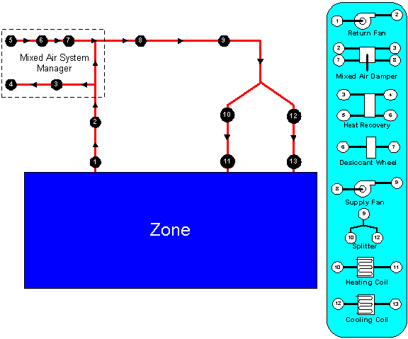
Figure 61. Example Node Diagram
So that these loops are manageable and more clearly defined both in the input and in the simulation, four different loop sections can be defined in an EnergyPlus input file. In general, these four types are in essence two pairs of loop sections that make up two distinct types of loops: a zone/air loop and a plant loop. As of Version 7, plant loops and condenser loops have been consolidated to be largely the same. The four loop section types are defined below.
Air Loop Supply Side: The air loop is defined by the section of the zone/air loop that starts after the zone return streams are combined and continues on until just before any air stream(s) are branched off to individual zones. The starting point of the air loop is fairly straightforward. The ending point is slightly more complex but can be understood with some examples. For instance, in a terminal reheat system, the end of the air loop would typically be considered the node following the cooling coil. In a dual duct system, the air loop would have two ending points that would correspond to the nodes after the cooling coil and after the heating coil/humidifier. In most cases, the air loop has a single starting point and up to two ending points (for a 2 deck system). An outdoor air subsystem can be included in the supply side for ventilation and relief air.
Air Loop Zone Equipment: The zone equipment section of the input file is defined as more or less the rest of the zone/air loop (outside air is handled separately as a subset of the air loop). This includes everything from where the ducts are split to serve various zones up through where the return ducts from various zones are mixed into a single return duct. Zone equipment can include dampers and reheat coils as well as zone specific conditioning systems such as thermostatic baseboard or a window air conditioner. Most control issues are typically dealt with in the zone equipment section of the simulation.
Plant Loop Demand Side: One side of the plant is where energy is “demanded” by various components that make up the air loop or zone equipment. Typically, this is the water side of equipment such as coils, baseboard, radiant heating and cooling, etc. In the case of a condenser loop, energy is typically “demanded” by a chiller condenser or other water source heat pump. The demand side of this loop can also include mixers, flow splitters, and a bypass.
Plant Loop Supply Side: The other side of the plant loop is where energy is “supplied” by various components. The components typically found on the supply side include pumps, boilers, chillers, purchased heating and cooling, ice storage, etc. In the case of a condenser, the components would be cooling tower, fluid cooler, or ground source heat exchanger, etc. As with the demand side, this loop can also include mixers, flow splitters, and a bypass.
The section of the input file for describing the HVAC system tends to follow this structure presented above. Both plant and condenser loops are defined with a master description and then branch off into supply and demand side details. Linkage between the two sides is done using node names in the master statement. The air loop and zone equipment descriptions are slightly more complex due to the wide range of potential systems that are anticipated. Note that in every section controls become a key element and must be addressed. Each of the following sections details either a loop, a portion of a loop, or controls.
Nodes, Branch Lists and Branches define the topography of the HVAC connections.
For convenience, the NodeList object can be used to identify all the nodes for a particular use. A node list is not always required. The advantage of listing all the nodes in this manner is that input fields in other objects that ask for a node name can refer to either a single node or a list of nodes using this object. .
There are other lines of input syntax that require the use of a NodeList as part of the input. These syntax items include: OutdoorAir:NodeList and the SetpointManager objects. In these two cases, the use of a NodeList statement is mandatory if there is more than one node in this particular “list”. For example, if the outside air only has a single inlet node, then the name of that node can replace the node list name in the input syntax. As a result of this mandatory specification of node lists for certain types of input, nodes can, obviously, and may be members of more than one list.
This alpha designation must be unique among all the Node List Names. It is used as reference in various objects (e.g. OutdoorAir:NodeList).
Each unique Node identifier creates a Node structure with various attributes depending on the type of node. Typical values include Temperature, Mass Flow Rate, and Temperature Set Point. The alpha designators are associated with a particular node.
Though each NodeList is limited to 25 nodes, several node lists may be entered if you choose to identify all the nodes up front. For example:
NodeList, Nodes1-25,
NODE_1,NODE_2,NODE_3,NODE_4,NODE_5,NODE_6,NODE_7,NODE_8,NODE_9,NODE_10,
NODE_11,NODE_12,NODE_13,NODE_14,NODE_15,NODE_16,NODE_17,NODE_18,NODE_19,NODE_20,
NODE_21,NODE_22,NODE_23,NODE_24,NODE_25;
NodeList, Nodes26-49,NODE_26,NODE_27,NODE_28,NODE_29,NODE_30,
NODE_31,NODE_32,NODE_33,NODE_34,NODE_35,NODE_36,NODE_37,NODE_38,NODE_39,NODE_40,
NODE_41,NODE_42,NODE_43,NODE_44,NODE_45,NODE_46,NODE_47,NODE_48,NODE_49;
A simple detail of Nodes and numbers assigned appears in the eplusout.bnd file:
! <Node>,<NodeNumber>,<Node Name>,<Node Fluid Type>,<# Times Node Referenced After Definition>
Node,1,OUTSIDE AIR INLET NODE 1,Air,2
Node,2,VAV SYS 1 INLET NODE,Air,3
Node,3,MIXED AIR NODE 1,Air,5
Node,4,MAIN COOLING COIL 1 OUTLET NODE,Air,3
Node,5,MAIN HEATING COIL 1 OUTLET NODE,Air,4
Node,6,VAV SYS 1 OUTLET NODE,Air,7…
In addition, properties of each node is available during the simulation:
HVAC,Average,System Node Temp[C]
HVAC,Average,System Node MassFlowRate[kg/s]
HVAC,Average,System Node Humidity Ratio[]
HVAC,Average,System Node Setpoint Temp[C]
HVAC,Average,System Node Setpoint Temp Hi[C]
HVAC,Average,System Node Setpoint Temp Lo[C]
HVAC,Average,System Node Setpoint Humidity Ratio[]
HVAC,Average,System Node Setpoint Humidity Ratio Min[]
HVAC,Average,System Node Setpoint Humidity Ratio Max[]
HVAC,Average,System Node Relative Humidity[%]
HVAC,Average,System Node Pressure[Pa]
HVAC,Average,System Node Volume Flow Rate Standard Density [m3/s]
HVAC,Average,System Node Enthalpy[J/kg]
HVAC,Average,System Node Wetbulb Temp[C]
HVAC,Average,System Node Quality[]
HVAC,Average,System Node Height[m]
The following node variable is also available for system nodes that are for “air”:
HVAC, Average, System Node Volume Flow Rate Current Density [m3/s]
HVAC, Average, System Node Current Density [kg/m3]
The following node variables are “advanced” and normally used for debugging unusual cases:
HVAC,Average,System Node TempMin[C]
HVAC,Average,System Node TempMax[C]
HVAC,Average,System Node MassFlowRateMin[kg/s]
HVAC,Average,System Node MassFlowRateMax[kg/s]
HVAC,Average,System Node MassFlowRateMinAvail[kg/s]
HVAC,Average,System Node MassFlowRateMaxAvail[kg/s]
HVAC,Average,System Node MassFlowRateSetPoint[kg/s]
The following node variable reports node carbon dioxide concentration when carbon dioxide is simulated (ref. ZoneAirContaminantBalance):
HVAC,Average,System Node Carbon Dioxide Concentration [ppm]
The current temperature at a system node in degrees C. For air nodes, this is the dry-bulb temperature.
The current mass flow rate at a system node in kg/s.
The current humidity ratio at a system node in kg-water/kg-dry-air. Not applicable for liquid nodes.
The current setpoint temperature at a system node in degrees C. Some controllers and equipment types sense this single setpoint.
The current upper setpoint temperature at a system node in degrees C. Some controllers and equipment types use dual setpoints at a single node.
The current upper setpoint temperature at a system node in degrees C. Some controllers and equipment types use dual setpoints at a single node.
The current humidity ratio setpoint at a system node in kg-water/kg-dry-air. Some controllers and equipment types sense this single setpoint. Not applicable for liquid nodes.
The current minimum desired humidity ratio at a system node in kg-water/kg-dry-air. Some controllers and equipment types use the min/max values as dual setpoints at a single node. Not applicable for liquid nodes.
The current maximum desired humidity ratio at a system node in kg-water/kg-dry-air. Some controllers and equipment types use the min/max values as dual setpoints at a single node. Not applicable for liquid nodes.
The current relative humidity (calculated from the node temperature, node humidity ratio and standard barometric pressure for the location). Not applicable for liquid nodes.
The current pressure at a system node in Pa.
The current volume flow rate at a system node in m3/s. This is report is calculated from the mass flow using standardized values for density that do not vary over time (except for steam which varies with quality). For water nodes this density is determined at a temperature of 5.05ºC. For air nodes this density is determined for dry air at the standard barometric pressure for the location’s elevation, and a temperature of 20.0ºC. For air nodes, also see the report “System Node Volume Flow Rate Current Density.”
The current enthalpy at a system node in J/kg.
The current wet-bulb temperature at a system node in degrees C. Not applicable for liquid nodes.
The current system node vapor fraction/percent {0.0-1.0}.
The current system node height {m}. Only applicable to outdoor air nodes.
Additional Node Reporting for Air Nodes
The following system node variable is available for nodes with a fluid type of air.
The current volume flow rate at a system node in m3/s based on the current density. This report differs from the one called “System Node Volume Flow Rate Standard Density” in that it uses an air density calculated for the current moist air conditions rather than a standard density.
The current air density at a system node in kg/m3. This is the density used to calculate the volume flow rate above. The density is calculated using current outdoor air barometric pressure and the drybulb temperature and humidity ratio at the air node.
Advanced Node Reporting
The following system node variables are available when you request “Diagnostics, DisplayAdvancedReportVariable;”. They are normally used for debugging unusual system cases and may not be available for all systems. Also, their definitions may change based on the usage in the system.
These node variables represent the min/max of loops or branches.
These node variables hold the maximum possible and the minimum allowable flow rates for a particular component. As such, they represent the “hardware limit” on the flow rate for the component. By convention, these variables are stored at the component inlet node. Since components share their nodes (the outlet node of one component is the inlet node of the next component), the protocol must be strictly followed. These variables are set by each component based on the design flow limits of the equipment.
These node variables represent the loop or branch maximum and minimum flow rate for the current configuration of the loop on which the component resides. The central plant routines manage these variables dynamically to resolve flow rates through branches located inside splitters and mixers.
The current mass flow rate setpoint at a system node in kg/s. Some controllers and equipment types sense this single setpoint.
This output is the current mass flow rate request at a system node in kg/s. Only used for plant simulations and nodes. This is the mass flow rate “requested” by a component. This is a record of what the component wanted which can be useful for diagnostics when the actual simulated flow is different than expected. This value is also used to determine overall loop flow rates.
The average carbon dioxide concentration, in parts per million (ppm), at a system node for the timestep being reported.
A branch list is intended to define the branches or portions of a particular loop that are present on an individual plant or condenser loop. Thus, the BranchList syntax simply provides a list of branch names (see Branch syntax) that then refer to more detailed syntax in another part of the input file. The syntax for describing a list of branches is given below.
Branches in BranchList objects should be listed in flow order: inlet branch, then parallel branches, then outlet branch. Branches (within a splitter/mixer) are simulated in the order listed.
A unique name to identify the branch list.
Branch name in the list. As noted above, Branches in BranchList objects MUST be listed in flow order: inlet branch, then parallel branches, then outlet branch. Branches are simulated in the order listed.
An example of this statement in an IDF is:
BranchList, Cooling Supply Side Branches,
CW Pump Branch,
Little Chiller Branch,
Big Chiller Branch,
Purchased Cooling Branch,
Supply Bypass Branch,
Cooling Supply Outlet;
No output directly related to Branch Lists current is presented.
Branches can be considered the mid-level grouping of items in the EnergyPlus HVAC loop scheme. Components are the lowest level of information. A collection of components in series forms a branch. Every branch must have at least one component, but it may have several components in series. The branch defines the order that components appear on the branch. Moreover, a collection of branches and their connecting information form a loop. Therefore, a branch is a collection of components while a loop is a collection of branches. Thus, components are specified for particular HVAC loops by assigning them to branches and then connecting those branches together to form a loop. It should be noted that each component also has at least two nodes associated with it—an inlet node and an outlet node. These nodes, by default, are also part of the branch to which their components are assigned. It should be noted that each branch must have at least one component on it. A “null” branch such as one where the first component on the loop is in reality a splitter or mixer should be defined as a single Pipe component.
This alpha field is the identifying name that allows the branch to be referenced by other elements such as the PlantLoop and CondenserLoop statements.
This field is the maximum flow rate (m3/sec) allowed on a particular branch. This number will set an absolute maximum flow rate for all components on the loop. Even if components are defined with a higher flow rate, EnergyPlus will limit the flow on this particular branch to the value entered here by the user. Currently this is used in the Air Loop and is not a required field in the Plant and Condenser Loop. The example files for the Plant and Condenser Loops leave this field blank to simplify flow input.
This is an optional field used to specify pressure drop information for this particular branch. Currently this is only available in fluid loops: PlantLoop’s and CondenserLoop’s. Air loops require a full airflow network, so this field is ignored if found on an air loop. The value entered for this field must match a pressure curve object also found in the input. This curve can be of the type: Curve:Linear, Curve:Quadratic, Curve:Cubic, Curve:Exponent, or Curve:Functional:PressureDrop. In order to then perform a pressure simulation for the loop that this branch is located on, a flag must be set in the loop object. Reference the PlantLoop and CondenserLoop field “Pressure Simulation Type” for allowable settings. See the Engineering Reference document for further information on pressure simulation in plant loops.
Following the two introductory items, there are up to eleven groups of 5 repeated items: a type, a name, inlet and outlet node names, and a branch control type. All of these items refer to a particular component on the branch. The first component defined by these items will be the first component on this branch, etc. through the end of the list.
This field is the component object type (object name). The component type refers to other elements within the input file and specifies what kind of component this is. The objects in the Group – Plant Equipment section are valid here when the Branch is used in Plant specifications. Fans, coils and Outside Air Systems are also valid component types for the Branch object. Pipes are also valid for this field.
The component name is a reference name to distinguish between potentially multiple occurrences of a particular component type in an input file. The set of component type and component name must be unique. (You can only have 1 Boiler object with name MYBOILER).
This field references an inlet node name that will be found in the actual component specification.
This field references an outlet node name that will be found in the actual component specification.
This field is being deprecated and no longer used. Prior to version 7 it was used by plant to resolve branch flow rates but now this is handled automatically by the program. An example of this statement in an IDF is:
Branch,
Air Loop Main Branch, !- Branch Name
1.75, !- Maximum Branch Flow Rate {m3/s}
, !- Pressure Drop Curve Name
AirLoopHVAC:UnitaryHeatCool:VAVChangeoverBypass, !- Comp1 Type
GasHeat CBVAV System, !- Comp1 Name
Air Loop Inlet Node, !- Comp1 Inlet Node Name
Air Loop Outlet Node, !- Comp1 Outlet Node Name
Active; !- Comp1 Branch Control Type
And a more complex one:
BRANCH,
Air Loop Main Branch, !- Branch Name
1.3, !- Maximum Branch Flow Rate {m3/s}
, !- Pressure Drop Curve Name
FAN:SIMPLE:ConstVolume, !- Comp1 Type
Supply Fan 1, !- Comp1 Name
Air Loop Inlet Node, !- Comp1 Inlet Node Name
Cooling Coil Air Inlet Node, !- Comp1 Outlet Node Name
Active, !- Comp1 Branch Control Type
COIL:Water:DetailedFlatCooling, !- Comp2 Type
Detailed Cooling Coil, !- Comp2 Name
Cooling Coil Air Inlet Node, !- Comp2 Inlet Node Name
Air Loop Outlet Node, !- Comp2 Outlet Node Name
Passive; !- Comp2 Branch Control Type
The components on a branch are in series and that list is in simulation and connection order. Each branch must obey the rules: the outlet for component 1 has to have the same node name as the inlet for component 2, and so forth.
Eplusout.err contains the test for “individual branch integrity”:
************* Testing Individual Branch Integrity
************* Testing Branch=AIR LOOP MAIN BRANCH
************* ....passed
************* Testing Branch=COOLING DEMAND INLET
************* ....passed
************* Testing Branch=COOLING COIL BRANCH
************* ....passed
************* Testing Branch=DEMAND BYPASS BRANCH
************* ....passed
************* Testing Branch=COOLING DEMAND OUTLET
************* ....passed
************* Testing Branch=COOLING SUPPLY OUTLET
************* ....passed
The addition of pressure simulation for branches in fluid loops brings a new output at the branch level:
HVAC,Average,Branch Pressure Drop [Pa]
This field allows the user to output the pressure drop of a particular branch on a plant loop or condenser loop. This output is only recognized if a valid pressure simulation is being performed. To do this, the user must specify a pressure simulation type as an input in the PlantLoop or CondenserLoop object.
A connector list is a collection of either one or two connection devices (Connector:Mixer or Connector:Splitter). Due to the definition of a loop in EnergyPlus, there is a maximum of one mixer and one splitter allowed for each loop segment. This limitation still allows a tremendous amount of flexibility to the user and can also still be solved within a reasonable amount of time and without a complex solver routine. The connection list simply allows the specification of the types and names of these devices. This allows the main loop statements to have the flexibility to have multiple lists that can have one or more item.
This field is an identifying name that will be referenced to main loop statements using this connector list. The name must be unique among connector list names.
Depending on the loop, either one or two of the connectors will be specified. If this particular loop only has a single connector (either Connector:Mixer or Connector:Splitter), then only the first two items (type of connection and identifying name of connector) are included. If both a mixer and splitter are present, the additional type of connection and identifying name must be included. Note that the order that the items appear is inconsequential—either the Connector:Mixer or the Connector:Splitter may appear first. This will not affect the simulation.
This field contains the connector type Connector:Mixer or Connector:Splitter.
This field is an identifying name for the connector. It will be used by other objects in the input file.
This field contains the connector type Connector:Mixer or Connector:Splitter.
This field is an identifying name for the connector. It will be used by other objects in the input file.
An example of this statement in an IDF is:
ConnectorList LIST, Cooling Supply Side Connectors,
Connector:Splitter, CW Loop Splitter,
Connector:Mixer, CW Loop Mixer;
No output directly related to Connector Lists is currently presented.
In reality, every component is connected to its closest neighbors via a pipe or a duct. At the current time, such detail is not needed in EnergyPlus. Thus, the Pipe:Adiabatic component is currently used more as a connection device (for branches that really do not have any components associated with them) or as a bypass than anything else. As such, its input is very simple and its algorithm is equally simple. The current algorithm for a pipe is simply to pass the inlet conditions to the outlet of the pipe component.
This alpha field is used as an identifying field for the pipe.
This alpha field is used as an identifying field for the pipe inlet node.
This alpha field is used as an identifying field for the pipe outlet node.
An example of this statement in an IDF is:
Pipe:Adiabatic,
Demand Side Inlet Pipe,
CW Demand Inlet Node,
CW Demand Entrance Pipe Outlet Node;
There are no outputs directly related to Pipes.
To connect the various components in a steam system regardless of it being the condensate or the steam side of the loop steam pipe needs to be used. In reality, every component is connected to its closest neighbors via a pipe or a duct. At the current time, such detail is not needed in EnergyPlus. Thus, the Pipe:Adiabatic:Steam component is currently used more as a connection device (for branches that really do not have any components associated with them). As such, its input is very simple and its algorithm is equally simple. The current algorithm for a pipe is simply to pass the inlet conditions to the outlet of the pipe component.
This alpha field is used as an identifying field for the steam pipe.
This alpha field is used as an identifying field for the steam pipe inlet node.
This alpha field is used as an identifying field for the steampipe outlet node.
An example of this statement in an IDF is:
Pipe:Adiabatic:Steam,
Steam Demand 1 Steam Inlet Pipe, !- PipeName
Steam Demand 1 Steam Demand Inlet Node, !- Inlet Node Name
Steam Demand 1 Steam Demand Entrance Pipe Outlet Node; !- Outlet Node Name
There are no outputs directly related to Steam Pipes.
This object specifies inputs which are used to simulate the heat transfer from a plant loop pipe placed in a zone or when a user schedule is used to specify an environment.
The data definition for object is shown below.
This alpha field is used as an identifying field for the pipe.
This alpha field references a 'wall' construction object that gives a layer-by-layer description of the pipe wall and its insulation. The construction object follows standard conventions, describing material properties for each layer beginning with the outermost insulation layer and ending with the pipe wall layer.
This alpha field contains the name of the pipe fluid inlet node.
This alpha field contains the name of the pipe fluid outlet node.
Environment type is the environment in which the pipe is placed. It can be either Zone or Schedule. If specified as Zone, a zone name must be specified in the next field. If specified as Schedule, the Ambient Temperature Zone can be left blank, while a schedule must be specified for the temperature and air velocity.
If Zone is specified as the environment type, this field is used to specify the name of the zone in which the pipe is located. The zone temperature is used to calculate the heat transfer rate from the pipe.
If Schedule is specified as the environment type, this field is used to specify the name of the temperature schedule that gives the ambient air temperature surrounding the pipe. This temperature is used as the outside boundary condition to calculate heat transfer from the pipe.
If Schedule is specified as the environment type, this field is used to specify the name of the velocity schedule that gives the air velocity near the pipe. This velocity is used to calculate the convection heat transfer coefficient used in the pipe heat transfer calculation.
This field is used to enter the inside diameter of the pipe in units of m. Pipe inside diameter must be a positive number.
This field is used to enter the length of the pipe in units of m. Pipe length must be a positive number.
An example of this object in an IDF is:
Pipe:Indoor,
Pipe Heat Transfer Towers, !- name of outside panel heat exchanger
Insulated Pipe, !- Construction name
Condenser Tower Outlet Node, !- Comp1 Inlet Node Name
HTPipe Outlet Node, !- Comp1 Outlet Node Name
Water, !- Fluid name
Zone, !- field Ambient Temperature Outside Air Node name
0.05, !- Pipe Inside Diameter (thickness in construction data)
100.0; !- pipe length
HVAC,Average, Pipe Heat Transfer Fluid Heat Transfer Rate [W]
HVAC,Average, Pipe Heat Transfer Environmental Heat Transfer Rate [W]
HVAC,SUM, Pipe Heat Transfer Fluid Heat Transfer Energy [J]
HVAC,SUM, Pipe Heat Transfer Environmental Heat Transfer Energy [J]
HVAC,Average, Pipe Heat Transfer Fluid Mass Flow Rate [kg/s]
HVAC,Average, Pipe Heat Transfer Fluid Inlet Temperature [C]
HVAC,Average, Pipe Heat Transfer Fluid Outlet Temperature [C]
HVAC,Average, Pipe Heat Transfer Fluid Volume Flow Rate [m3/s]
The output provides the total amount of heat loss/gain in the fluid from pipe inlet to outlet.
The output provides the amount of heat loss/gain from pipe wall to the environment.
Total energy fluid has lost/gained between pipe inlet and outlet. It is metered on EnergyTransfer with an end use of Pipes.
Total energy lost from the external pipe surface.
Mass flow rate of the fluid in the pipe.
Temperature of fluid at entering and exiting of pipe.
Fluid volumetric flow rate, (mass flow rate / density)
This object specifies inputs which are used to simulate the heat transfer from a plant loop pipe placed in an outdoor environment.
This alpha field is used as an identifying field for the pipe.
This alpha field references a 'wall' construction object that gives a layer-by-layer description of the pipe wall and its insulation. The construction object follows standard conventions, describing material properties for each layer beginning with the outermost insulation layer and ending with the pipe wall layer.
This alpha field contains the name of the pipe fluid inlet node.
This alpha field contains the name of the pipe fluid outlet node.
Ambient temperature outdoor air node is a node representing outdoor air with which pipe transfers heat. The node should be included in an outdoor air node list.
This field is used to enter the inside diameter of the pipe in units of m. Pipe inside diameter must be a positive quantity.
This field is used to enter the length of the pipe in units of m. Pipe length must be a positive quantity.
An example of this statement in an IDF is:
Pipe:Outdoor,
Pipe Heat Transfer Towers, !- name of outside panel heat exchanger
Insulated Pipe, !- Construction name
Condenser Tower Outlet Node, !- Comp1 Inlet Node Name
HTPipe Outlet Node, !- Comp1 Outlet Node Name
Water, !- Fluid name
PipeHeatTransfer Inlet Node, !- field Ambient Temperature Outside Air Node name
0.05, !- Pipe Inside Diameter (thickness given in construction data)
100.0; !- pipe length
HVAC,Average, Pipe Heat Transfer Fluid Heat Transfer Rate [W]
HVAC,SUM, Pipe Heat Transfer Fluid Heat Transfer Energy [J]
HVAC,Average, Pipe Heat Transfer Fluid Mass Flow Rate [kg/s]
HVAC,Average, Pipe Heat Transfer Fluid Inlet Temperature [T]
HVAC,Average, Pipe Heat Transfer Fluid Outlet Temperature [T]
HVAC,Average, Pipe Heat Transfer Fluid Volume Flow Rate [m3/s]
The output provides the total amount of heat loss/gain in the fluid from pipe inlet to outlet.
Total energy fluid has lost/gained between pipe inlet and outlet. It is metered on EnergyTransfer with an end use of Pipes.
Mass flow rate of the fluid in the pipe.
Temperature of fluid at entering and exiting of pipe.
Fluid volumetric flow rate, (mass flow rate / density)
This object specifies inputs which are used to simulate the heat transfer from a plant loop pipe placed underground.
This alpha field is used as an identifying field for the pipe.
This alpha field references a basic construction object that gives a layer-by-layer description of the pipe wall and insulation. The construction object follows standard conventions, describing material properties for each layer beginning with the outermost layer, the insulation, if it exists, and ending with the pipe wall layer. The construction object may have either one or two layers. If only one, then the material must be the pipe wall. If two, then insulation is utilized.
This alpha field contains the name of the pipe fluid inlet node.
This alpha field contains the name of the pipe fluid outlet node.
This alpha field allows the user to specify one of two options: NoSun or SunExposed. For SunExposed, the simulation includes diffuse and beam solar effects on the ground surface. For NoSun, no solar effects are included.
This field is used to enter the inside diameter of the pipe in units of m. Pipe inside diameter must be a positive quantity.
This field is used to enter the length of the pipe in units of {m}. Pipe length must be a positive quantity.
This references a Material object that contains the soil properties and thickness. Note that when defining the soil layer, the thickness should be the thickness of soil between the pipe wall and the ground surface.
If a GroundTemperatures:Surface object is not given in the input, this is #1 of 3 inputs that must be given directly. This represents the annual average soil temperature above the pipe. This field can be calculated in advance using the separate CalcSoilSurfTemp program.
If a GroundTemperatures:Surface object is not given in the input, this is #2 of 3 inputs that must be given directly. This represents the annual average soil temperature variation from the average temperature itself. For example, if this were represented as a sine wave, this would simply be the amplitude of the curve. This field can be calculated in advance using the separate CalcSoilSurfTemp program.
If a GroundTemperatures:Surface object is not given in the input, this is #3 of 3 inputs that must be given directly. This represents the time elapsed from the beginning of the year to the date of minimum surface temperature. For example, if this were represented as a sine wave, this would simply be the phase shift of the curve. This field can be calculated in advance using the separate CalcSoilSurfTemp program
In order to avoid having to run the preprocessor program to generate soil temperature, the user may choose to simply input a GroundTemperatures:Surface object. This object inputs average monthly surface temperatures. These temperatures are then used within the model to develop average ground surface data. This ground surface data can then be used as part of the model boundary condition set. Without a set of surface ground temperatures, the model will require user input of the three last input fields.
An example of this object in an IDF is:
Pipe:Underground,
Pipe Heat Transfer Towers, !- Name of Pipe
Insulated Buried Pipe, !- Construction Name
Condenser Tower Outlet Node, !- Inlet Node Name
HTPipe Outlet Node, !- Outlet Node Name
Water, !- Fluid Name
SunExposed, !- Sun Exposure
0.05, !- Pipe Inside Diameter
20.0, !- pipe Length
Buried Pipe Soil, !- Soil Material
13, !- Average Soil Surface Temperature
1.5, !- Amplitude of Soil Surface Temperature
30; !- Phase Constant of Soil Surface Temperature
Construction,
Insulated Buried Pipe, !- Name
Buried Pipe Insulation, !- Layer #1
Buried Pipe Steel; !- Layer #2
Material,
Buried Pipe Soil, !- Name
Smooth, !- Roughness
1.5, !- Thickness {m}
0.36, !- Conductivity {W/m-K}
2000.0, !- Density {kg/m3}
1200.0, !- Specific Heat {J/kg-K}
0.9, !- Thermal Absorptance
0.5, !- Solar Absorptance
0.5; !- Visible Absorptance
HVAC, Average, Pipe Heat Transfer Fluid Heat Transfer Rate [W]
HVAC, SUM, Pipe Heat Transfer Fluid Heat Transfer Energy [J]
HVAC, Average, Pipe Heat Transfer Fluid Mass Flow Rate [kg/s]
HVAC, Average, Pipe Heat Transfer Fluid Volume Flow Rate [m3/s]
HVAC, Average, Pipe Heat Transfer Fluid Inlet Temperature [C]
HVAC, Average, Pipe Heat Transfer Fluid Outlet Temperature [C]
The output provides the total amount of heat loss/gain in the fluid from pipe inlet to outlet.
Total energy fluid has lost/gained between pipe inlet and outlet. It is metered on
EnergyTransfer with an end use of Pipes.
Mass flow rate of the fluid in the pipe.
Fluid volumetric flow rate, (mass flow rate / density)
Temperature of fluid at entrance and exit of pipe.
Objects in this class are used to simulate the heat transfer processes of a piping system placed underground, which may or may not be in contact with a number of zone surfaces. There are three related objects, all of which are prefixed with PipingSystem:Underground :
n PipingSystem:Underground:Domain
n PipingSystem:Underground:PipeCircuit
n PipingSystem:Underground:PipeSegment
This section documents the domain object, which is used to specify information for the overall ground domain, including thermal properties, mesh parameters, and surface interaction.
This alpha field is used as an identifying field for the ground domain.
These numeric fields are used to specify the overall domain size, in each of the three Cartesian dimensions. The domain will be meshed from {x, y, z} = {0, 0, 0} to {Xmax, Ymax, Zmax}.
Note that for this object, the x-z plane lies parallel to the ground surface, such that the y-dimension can be thought of as representing the burial depth. This is in contrast to the way building surface coordinates are defined with the x-y plane lying parallel to the ground. Also note that any pipe segments that end up being used in a ground domain will be placed axially in the z-dimension. Thus, pipe flow will always be in either the positive z or negative z direction.
This numeric integer field represents the number of cells to be placed between any two “domain partitions” during mesh development. A domain partition may be thought of as a basement wall/floor, or a pipe. Once these components are laid out in the domain, this field number of cells are placed between the partitions. Further information on this is found in the engineering reference manual.
This alpha field represents the type of mesh to create when placing cells between “domain partitions.” Two options are available: “uniform” and “symmetricgeometric.” For uniform, the cells are placed in the region with all cells having equal size. For symmetric-geometric, the cells are compressed toward the partitions so that there are more cells on either side of the mesh region. This can help focus computational intensity on the boundary areas where it is likely more desired. For symmetric-geometric mesh distribution, the mesh density parameter should be an even number to provide the symmetric condition.
This numeric field represents the compression of cell distribution if the x-direction mesh type is set to “symmetricgeometric.” If the mesh type is uniform, this field is not interpreted. For symmetric geometric, a value in this field equal to 1 would result in a uniform distribution, while a value of 2 would provide a highly skewed distribution.
See Field: X-Direction Mesh Density Parameter.
See Field: X-Direction Mesh Type.
See Field: X-Direction Geometric Coefficient.
See Field: X-Direction Mesh Density Parameter.
See Field: X-Direction Mesh Type.
See Field: X-Direction Geometric Coefficient.
The thermal conductivity of the soil, in W/m-K.
The bulk density of the soil, in kg/m3.
The specific heat of dry soil, in J/kg-K. If moisture is defined in this object, moisture and freezing effects are accounted for by varying the specific heat value.
A nominal value of soil moisture content to be used when evaluating soil thermal properties.
A nominal value of soil moisture content when the soil is saturated, this is used in evaluating thermal properties of freezing soil
The annual average surface temperature to be applied to the Kusuda-Achenbach farfield boundary temperature correlation.
The annual average surface temperature variation from average. This is also used in the Kusuda-Achenbach temperature correlation.
The phase shift of minimum surface temperature, or the day of the year when the minimum surface temperature occurs.
A yes/no field stating whether zone surfaces should be coupled to this domain.
If this domain does include basement interaction, this represents the width of the domain cutaway to include the basement. In essence, this is the width of basement floor to include in the ground simulation. This width should include the basement wall thickness.
If this domain does include basement interaction, this represents the depth of the domain cutaway to include the basement. In essence, this is the burial depth of the basement to include in the ground simulation. This depth should include the basement floor thickness.
If this domain does include basement interaction, this flag specifies whether the pipe segment X-values should then be shifted by the basement width. In essence, this specifies the reference point for pipe segment x-values: if NO then the reference is domain x=0, if YES then the reference is the basement width point.
The name of an OtherSideConditions model defined in the input file and referenced by the surfaces which should be included as “wall surfaces” for the basement interaction part of the ground heat transfer model.
The name of an OtherSideConditions model defined in the input file and referenced by the surfaces which should be included as “floor surfaces” for the basement interaction part of the ground heat transfer model.
The maximum temperature deviation within any cell between one iteration and another to decide that the Cartesian domain has converged to within tolerance. A smaller value will improve accuracy and computation time. A smaller value should be accompanied by a higher number of iterations if maximum accuracy is desired.
The maximum number of iterations to make when performing temperature updates of the Cartesian coordinate system. The actual number of iterations made will of course depend on transient conditions and convergence tolerance.
The number of pipe circuit objects which will be defined in the following fields.
A PipingSystem:Underground:PipeCircuit to be included in this domain. This indicates that the pipe circuit and all of the underlying pipe segments will be included during mesh development and heat transfer calculations within this domain. Any number of pipe circuits can be added, assuming all underlying pipe segments do not cause any conflicts for the mesh development engine (overlapping pipes, etc.).
This section documents the pipe circuit object, which is used to specify information for the plant loop topology, such as inlet and outlet connections. This object also groups together pipe segments to define flow paths within a given pipe circuit.
This alpha field is used as an identifying field for the pipe circuit.
The thermal conductivity of the pipe, in W/m-K.
The bulk density of the pipe, in kg/m3.
The specific heat of the pipe, in J/kg-K.
The inner diameter of the pipe, in m.
The outer diameter of the pipe, in m.
The “design” flow in this pipe circuit, in m3/s. This is the flow which this component will request during the simulation. Of course, other components and overall plant management will decide the flow actually given to this component.
The inlet node name for this circuit, which is used when placing this circuit on a branch on a plant or condenser loop.
The outlet node name for this circuit, which is used when placing this circuit on a branch on a plant or condenser loop.
The maximum temperature deviation within any cell between one iteration and another to decide that the radial domain has converged to within tolerance. A smaller value will improve accuracy and computation time. A smaller value should be accompanied by a higher number of iterations if maximum accuracy is desired.
The maximum number of iterations to make when performing temperature updates of the radial coordinate system. The actual number of iterations made will of course depend on transient conditions and convergence tolerance.
The number of soil nodes to discretize pipe cells. More information on mesh development is provided in the engineering reference manual.
The radial distance used to discretize pipe cells. More information on mesh development is provided in the engineering reference manual.
The number of pipe segment objects which will be defined in the following fields.
A PipingSystem:Underground:PipeSegment to be included in this pipe circuit. The circuit is set up so that flow passes through the N segments in the order they are entered here.
This section documents the pipe segment object, which is used to specify information for a single pipe segment placed at some x, y coordinate in the ground. The flow direction is also defined in this object to allow for careful description of varying flow paths. This can be useful for accounting for short circuiting effects if two pipes are placed in counterflow vs. parallel flow.
This alpha field is used as an identifying field for the pipe segment.
This numeric field represents the x-direction placement of the pipe. If no basement is included in the simulation, this is measured from x=0. If a basement is included, and the domain object specifies that pipes should be shifted, this is measured from the basement wall.
This numeric field represents the burial depth of the pipe, measured from the ground surface. This will always be a positive number.
This alpha field is used to define the flow direction within this pipe segment. The choices are “increasing” or “decreasing.” These can be chosen carefully to encapsulate specific short-circuiting effects due to varying flow configurations (circuiting).
An example of this object in an IDF is offered here for a foundation heat exchanger
PipingSystem:Underground:Domain,
My Piping System, !- Name
12, !- Xmax
4.5, !- Ymax
36.84, !- Zmax
2, !- XMeshCount
Uniform, !- XMeshType
, !- XGeometricCoeff
2, !- YMeshCount
Uniform, !- YMeshType
, !- YGeometricCoeff
6, !- ZMeshCount
Uniform, !- ZMeshType
, !- ZGeometricCoeff
1.08, !- GroundThermalConductivity
962, !- GroundDensity
2576, !- GroundSpecificHeat
30, !- MoistureContent
50, !- MoistureContentAtSaturation
15.5, !- KusudaGroundTemp
12.8, !- KusudaGroundTempAmplitude
17.3, !- KusudaPhaseShift
Yes, !- DomainHasBasement
6, !- BasementWidthInDomain
2.5, !- BasementDepthInDomain
Yes, !- ShiftPipeXValuesByBasementWidth
BasementWallOSCM, !- BasementWallBoundaryConditionModel
BasementFloorOSCM, !- BasementFloorBoundaryConditionModel
0.005, !- CartesianIterationConvergenceCriterion
100, !- CartesianMaxIterations
0.408, !- EvapotranspirationGroundCoverParameter
1, !- NumPipeCircuits
My Pipe Circuit; !- PipeCircuit
PipingSystem:Underground:PipeCircuit,
My Pipe Circuit, !- Name
0.3895, !- PipeThermalConductivity
641, !- PipeDensity
2405, !- PipeSpecificHeat
0.016, !- PipeInnerDiameter
0.02667, !- PipeOuterDiameter
0.004, !- DesignFlowRate
Piping System Inlet Node, !- InletNode
Piping System Outlet Node, !- OutletNode
0.001, !- RadialIterationConvergenceCriterion
100, !- RadialMaxIterations
2, !- RadialMeshCount
0.03, !- RadialMeshThickness
6, !- NumSegments
Segment 1, !- Segment1
Segment 2, !- Segment2
Segment 3, !- Segment3
Segment 4, !- Segment4
Segment 5, !- Segment5
Segment 6; !- Segment6
PipingSystem:Underground:PipeSegment,
Segment 1, !- Name
0.67, !- X
2.20, !- Burial Depth
IncreasingZ; !- Flow Direction
PipingSystem:Underground:PipeSegment,
Segment 2, !- Name
0.95, !- X
2.20, !- Burial Depth
IncreasingZ; !- Flow Direction
PipingSystem:Underground:PipeSegment,
Segment 3, !- Name
1.23, !- X
2.20, !- Burial Depth
IncreasingZ; !- Flow Direction
PipingSystem:Underground:PipeSegment,
Segment 4, !- Name
1.40, !- X
1.94, !- Burial Depth
DecreasingZ; !- Flow Direction
PipingSystem:Underground:PipeSegment,
Segment 5, !- Name
1.40, !- X
1.66, !- Burial Depth
DecreasingZ; !- Flow Direction
PipingSystem:Underground:PipeSegment,
Segment 6, !- Name
1.40, !- X
1.39, !- Burial Depth
DecreasingZ; !- Flow Direction
HVAC, Average, Piping System Fluid Mass Flow Rate [kg/s]
HVAC, Average, Piping System Circuit Inlet Fluid Temperature [C]
HVAC, Average, Piping System Circuit Outlet Fluid Temperature [C]
HVAC, Average, Piping System Segment Inlet Fluid Temperature [C]
HVAC, Average, Piping System Segment Outlet Fluid Temperature [C]
The output provides the mass flow rate currently being sent through the pipe circuit.
Temperature of fluid at the inlet and outlet of a given pipe circuit.
Temperature of fluid at the inlet and outlet of a given pipe segment.
The Duct object is a component for air systems that is a direct analogue for Pipe:Adiabatic in the fluid loops. It is used when it is necessary (due to the HVAC system configuration) to have a branch that has no functional components. This case most often arises for a bypass branch. Since every branch must have at least one component, the Duct component is used for this situation. The duct is an adiabatic, pass-through component; all of its inlet conditions are passed through unchanged to its outlet.
This is the unique name for this component. Any reference to this component (in a BranchList, for instance) will refer to it by this name.
The name of the component’s air inlet node.
The name of the component’s air outlet node.
Below is an example input for Duct.
DUCT,
VAV Sys 1 Bypass Duct, !- Name
VAV Sys 1 Bypass Duct Inlet Node, !- Inlet Node Name
VAV Sys 1 Bypass Duct Outlet Node;!- Outlet Node Name
There are no outputs for Duct.
The main elements of the PlantLoop syntax are described in further detail below. A map of how the input for this portion of the HVAC input fits together is provided in the following diagram.
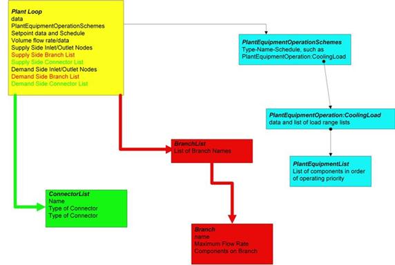
Figure 62. Plant Loop Input Syntax Map
This alpha field is used as an identifying field for the plant loop.
This alpha field must be a keyword selected from the list of available fluids for an EnergyPlus plant loop. Either Water, Steam or UserDefinedFluidType may be used. If the UserDefinedFluidType keyword is used, the following input field i.e. User Defined Fluid Type must have a value (namely the name of a FluidProperties:GlycolConcentration object).
This alpha field must be specified when the previous field is set to UserDefinedFluidType otherwise it could be left blank. Water, EthyleneGlycol, PropoleneGlycol and Steam are all “built-in” fluids for EnergyPlus (that is, all of the appropriate properties are contained within the program). If the fluid specified here is a mixture of water and ethylene or propylene glycol, then only FluidProperties:GlycolConcentration objects need to be specified and the name of the appropriate one is used here. For another water/glycol mixture, a complete set of fluid property data (FluidProperties:Name and FluidProperties:Temperature objects plus multiple FluidProperties:Concentration objects for specific heat, density, etc.) must be specified (Ref dataset: GlycolPropertiesRefData.idf).
This alpha field is used as an identifying field for the plant operation scheme. This field ties to the PlantEquipmentOperationSchemes input structure, which must also be defined.
This alpha field is used to identify the node which the Loop Manager will access the temperature setpoint that it will try to maintain. This is typically the Plant Loop Supply Side Outlet Node so that it will not interfere with component temperature setpoints. An associated temperature setpoint manager will need to be defined.
This numeric field contains the maximum allowable temperature in Celsius for this loop.
This numeric field contains the minimum allowable temperature in Celsius for this loop.
This numeric field contains the maximum loop flow rate in cubic meters per second. This parameter is also used when the user chooses to autocalculate the loop volume. See Volume of the Plant Loop below and the Engineering Manual for more details. This field is autosizable.
This numeric field contains the minimum loop flow rate in cubic meters per second.
Volume of the plant loop in m3. This numeric field contains the loop volume for the entire loop, i.e. both the demand side and the supply side. This is used for the loop capacitance calculation.. Loop volume (m3) could be calculated from pipe size data but this is not usually known. If zero volume is specified the loop has no fluid heat capacity. If a very large capacitance is specified unrealistic time delay may result and there may be poor response to changes in loop setpoint temperature. The loop capacitance autocalculate option gives reasonable values for most system sizes. This calculation is described in the Engineering Reference manual.
This required alpha field contains the identifying name given to the Plant Side Inlet Node. This node is the inlet to the supply side of the loop.
This required alpha field contains the identifying name given to the Plant Side Outlet Node. This node is the outlet of the supply side of the loop.
This required alpha field contains the identifying name given to the Plant Side Branch List. The list referenced here should list all the branches on the supply side of the loop.
This alpha field contains the identifying name given to the Plant Side Connector List. The list referenced here should list the splitter and mixer on the supply side of the loop.
This required alpha field contains the identifying name given to the Demand Side Inlet Node. This node is the inlet to the demand side of the loop.
This required alpha field contains the identifying name given to the Demand Side Outlet Node. This node is the outlet of the demand side of the loop.
This required alpha field contains the identifying name given to the Demand Side Branch List. The list referenced here should list all the branches on the demand side of the loop.
This alpha field contains the identifying name given to the Demand Side Connector List. The list referenced here should list the splitter and mixer on the demand side of the loop.
This alpha field contains the Load Distribution Scheme Keyword. The Load Distribution Scheme selects the algorithm used to sequence equipment operation in order to meet the plant loop demand. Currently, three schemes are functional. Sequential uses each piece of equipment to its maximum part load ratio and will operate the last required piece of equipment between its minimum and maximum part load ratio in order to meet the loop demand. Optimal operates each piece of equipment at its optimal part load ratio and will operate the last component between its minimum and maximum part load ratio in order to meet the loop demand. Uniform evenly distributes the loop demand among all available components on the equipment list for a given load range.
This alpha field contains the identifying name given to the System Availability Manager List.
There are two plant loop demand calculations schemes in EnergyPlus. There is a SingleSetpoint and a DualSetpointDeadband; the SingleSetpoint is the default if this field is left blank. In the SingleSetpoint scheme the Plant Loop requires that a Setpoint Manager set a single setpoint value (on Node%TempSetpoint). Examples of this setpoint manager would be: SetpointManager:Scheduled, SetpointManager:OutsideAir, etc. For the DualSetPointDeadband scheme the Plant Loop requires that a Setpoint Manager set the high and low setpoint values (for Node%TempSetPointHi and Node%TempSetPointLo). Examples of this Setpoint manager would be: SetpointManager:Scheduled:DualSetpoint.
The plant loop demand calculation scheme determines the amount of heating or cooling necessary to bring the temperature of the Plant Loop to its setpoint(s). When this value is determined then the load distribution scheme explained in the previous section takes this value and distributes the load to the appropriate equipment. The demand calculation scheme determines how the load is calculated. See more information in the Engineering Document.
This field specifies a primary-secondary plant loop simulation. When a common pipe option is specified, the plant side of the loop is the primary loop and the demand side of the loop is the secondary loop, and a pump object must be placed on the demand side inlet branch. The three options are “None”, “CommonPipe” and “TwoWayCommonPipe”. “None” means that there is no secondary loop and the plant loop is modeled as a single primary loop. “CommonPipe” means that the common pipe interface does not attempt any temperature control, it only satisfies secondary (demand side) flow requests. “TwoWayCommonPipe” allows control of the secondary (demand side) inlet temperature or the primary (plant side) inlet temperature by placing a setpoint on the corresponding node. If this field is left blank, it will default to ”None”. If the field is set to “None” and the program finds a pump on the demand side it will result in a fatal error. If the field is set to “CommonPipe” or “TwoWayCommonPipe” and the program does not find a pump on the demand side it will result in a fatal error. The common pipe simulation is currently limited to simulating loop pumps, i.e. each pump should be placed on the inlet branch of the plant side or demand side of the loop.
This field lets user to choose if this plant loop will be involved in a pressure drop calculation. This requires that at least one branch on the loop have pressure drop data. If not, an error will be thrown due to the input mismatch. Currently there are two pressure drop simulation types: “PumpPowerCorrection” and “LoopFlowCorrection”. In both of these methods, branch pressure drop data is used to calculate a dynamic loop pressure drop and is used to update pumping power accordingly. The flow correction method allows the user to enter information regarding the pressure curve of a constant speed pump so that the simulation can dynamically resolve the pressure vs. flow relationship in the plant loop. This is limited to constant speed pumps, as the variable speed pumps are expected to resolve as if it were controlled by a variable drive, so that they can inherently meet any pressure and flow demand required by the loop. This is also limited to “loop pumps”, where there is a single pump on the plant loop. Common pipe simulations and “branch pump” simulations are not compatible with this level of pressure simulation. See the documentation for the Pump:ConstantSpeed in order to determine required inputs for this pressure simulation method to be performed. In the pressure drop system, parallel flow rates are not resolved (to match the pressure drop for the parallel system). Enhancements to this calculation are planned which will allow parallel branch flow resolution. See the Engineering Reference document for more information on how this works.
An example of this statement used in an IDF is:
PlantLoop,
Hot Water Loop, !- Plant Loop Name
Water, !- Fluid Type
, !- User Defined Fluid Type
Hot Loop Operation, !- Plant Operation Scheme List Name
HW Loop Outlet Node, !- Loop Temperature Setpoint Schedule Name
100, !- Maximum Loop Temperature {C}
10, !- Minimum Loop Temperature {C}
autosize, !- Maximum Loop Volumetric Flow Rate {m3/s}
0.0, !- Minimum Loop Volumetric Flow Rate {m3/s}
autosize, !- volume of the plant loop {m3}
HW Supply Inlet Node, !- Plant Side Inlet Node Name
HW Supply Outlet Node, !- Plant Side Outlet Node Name
Heating Supply Side Branches, !- Plant Side Branch List Name
Heating Supply Side Connectors, !- Plant Side Connector List Name
HW Demand Inlet Node, !- Demand Side Inlet Node Name
HW Demand Outlet Node, !- Demand Side Outlet Nodes Name
Heating Demand Side Branches, !- Demand Side Branch List Name
Heating Demand Side Connectors, !- Demand Side Connector List Name
Optimal; !- Load Distribution Scheme
In the above example input there is no system availability manager specified and the Demand Calculation Scheme will default to SingleSetpoint using a single setpoint manager. Common pipe simulation field in the above example will default to “NONE” since it is not specified.
In the following output variables, “Debug” denotes variables that are used primarily by the developers and whose names and application may be cryptic to users. .
HVAC,Average,Plant Loop Cooling Demand[W]
HVAC,Average,Plant Loop Heating Demand[W]
HVAC,Average,Plant Loop InletNode Flowrate[kg/s]
HVAC,Average,Plant Loop InletNode Temperature[C]
HVAC,Average,Plant Loop OutletNode Temperature[C]
HVAC,Average,Plant Loop Demand Not Distributed [W]
HVAC,Average,Plant Loop Unmet Demand[W]
HVAC,Sum,Plant Manager Total Sub Iterations []
HVAC,Sum,Plant Manager Total Half Loop Calls []
HVAC,Average,Debug Plant Loop Bypass Fraction
HVAC,Average,Debug Last Loop Side Simulated [-]
HVAC,Average,Common Pipe Mass Flow Rate [Kg/s]
HVAC,Average,Common Pipe Flow Temperature [C]
HVAC,Average,Common Pipe Flow Direction []
HVAC,Average,Primary Side Common Pipe Mass Flow Rate [Kg/s]
HVAC,Average,Secondary Side Common Pipe Mass Flow Rate [Kg/s]
HVAC,Average,Primary Side Common Pipe Flow Direction []
HVAC,Average,Secondary Side Common Pipe Flow Direction []
HVAC,Average,Primary to Secondary Mass Flow Rate [Kg/s]
HVAC,Average,Secondary to Primary Mass Flow Rate [Kg/s]
HVAC,Average,Plant Loop System Cycle On/Off Status
HVAC,Average,Plant Loop Demand Side Pressure Drop [Pa]
HVAC,Average,Plant Loop Supply Side Pressure Drop [Pa]
HVAC,Average,Plant Loop Pressure Drop [Pa]
This is the value of the net demand required to meet the cooling setpoint of the loop. If the loop setpoint is met for the current HVAC timestep, Plant Loop Cooling Demand will equal sum of the total cooling demand from the demand side coils on the loop. It will also equal the cooling output of all chillers (or other cooling equipment) on the loop less any pump heat added to the fluid. For example, for a chilled water loop with one chiller and one pump serving one chilled water coil: Plant Loop Cooling Demand will equal the chiller evaporator heat transfer less the pump heat to fluid, and it will also equal the chilled water coil total cooling output.
If the plant loop setpoint is not met, Plant Loop Cooling Demand will equal the sum of the total cooling demand from the demand side coils on the loop plus the additional cooling required to bring the loop flow to setpoint. If the loop remains off setpoint for successive timesteps, the demand required to return to setpoint will repeat in each timestep until the loop reaches setpoint. For this reason, Plant Loop Cooling Demand should not be summed over time, because it will overstate the demand whenever the loop is off setpoint.
This is the value of the mass flow rate at the Inlet to Plant Loop on the supply side. There is not an associated Plant Loop outlet node flow rate since continuity must be maintained in the loop and the outlet must be the same.
This is the value of the temperature at the Inlet to the plant loop on the supply side.
This is the value of the temperature at the outlet to the plant loop on the supply side.
This is the value of the demand that could not be distributed to the plant equipment because of some constraint in the plant operation scheme. This is a record of the loop operation scheme supervisory controls after attempting to distribute the load. For example it would be non-zero in situations where the load is larger than the upper limit of capacities set for the plant equipment controls. This output is for before the equipment has actually been simulated whereas the separate output Plant Loop Unmet Demand is for after the equipment has simulated.
This is the value of the demand NOT provided by the plant equipment to meet the heating or cooling setpoint of the loop. The value is positive when the plant equipment cannot meet the setpoint, and the value is negative when the plant equipment provides more than enough heating or cooling to meet the setpoint. A negative value can happen when the amount of demand is smaller than the minimum capacity of the equipment using the minimum part load ratio.
This is the count of iterations that the overall plant simulation used over the period of time being reported. This high-level output is from the plant solver used for all the plant loops and condenser loops in the model.
This is the count of calls to model individual half-loops that occurred during the overall plant simulation over the period of time being reported. This includes all the half-loops for both plant loops and condenser loops.
This output gives the magnitude of the flow through common pipe. The value is averaged over the reporting interval.
This output gives the value of the temperature of the fluid flowing through common pipe. This value is averaged over the reporting interval.
This output gives the direction of flow in common pipe. The value is an integer and can be 0, 1 or 2. Since the output value is averaged over reporting interval, a non-integer value may be shown as an output when the reporting interval is not detailed. An output value of 0 means that there was no flow in common pipe. An output value of 1 means that the secondary flow is greater than primary flow, whereas a value of 2 means that primary flow is greater than secondary flow.
This report variable gives the mass flow in the primary side common pipe leg in a Two-Way common pipe simulation. Value is averaged over the reporting interval.
This report variable gives the mass flow in the secondary side common pipe leg in a Two-Way common pipe simulation. Value is averaged over the reporting interval.
This report variable gives the direction of flow in a primary side common pipe leg in a Two-Way Common Pipe Simulation. A value of zero means there was no flow in the pipe. A value of 1 means the flow was from top to bottom in EnergyPlus loop schematic. So for primary side, a value of 1 means the flow is from Primary side inlet to Primary side outlet and a value of 2 means flow is from Primary side outlet to Primary side inlet.
This report variable gives the direction of flow in a Secondary side common pipe leg in a Two-Way Common Pipe Simulation. A value of zero means there was no flow in the pipe. A value of 1 means the flow was from top to bottom in EnergyPlus loop schematic. So for Secondary side, a value of 1 means the flow is from Secondary side outlet to Secondary side inlet and a value of 2 means flow is from Secondary side inlet to Secondary side outlet. Note that this is opposite to the primary side common pipe.
This report variable gives the mass flow from primary to secondary side in a Two-Way common pipe simulation. Value is averaged over the reporting interval.
This report variable gives the mass flow from secondary to primary side in a Two-Way common pipe simulation. Value is averaged over the reporting interval.
This field is the availability status of a Plant Loop. This status flag is a result of the calculations made by the System Availability Manager(s) listed in a System Availability Manager List. When a single availability manager is used in a System Availability Manager List, this is also the availability status reported by the specific availability manager (Ref. System Availability Manager Outputs). When multiple availability managers are used in a System Availability Manager List, the loop availability status is determine by the rules associated with Plant Loops (see rules described for Group – System Availability Managers). The control status outputs are represented using integers 0 through 2.. These integers represent NoAction (0), ForceOff (1), and CycleOn (2). Since the status output is averaged, the output result may not correspond to the values described here when report variable frequencies other than detailed are used. Use the “detailed” reporting frequency (Ref. Report Variable) to view the availability status at each simulation timestep.
This field allows the user to output the demand side pressure drop of a plant loop. This output is only recognized if a valid pressure simulation is being performed. To do this, the user must specify a pressure simulation type as an input in the PlantLoop object, and input at least one pressure drop curve on a branch of the plant loop. This particular output is only relevant if the user puts that curve on the demand side of the loop.
This field allows the user to output the supply side pressure drop of a plant loop. This output is only recognized if a valid pressure simulation is being performed. To do this, the user must specify a pressure simulation type as an input in the PlantLoop object, and input at least one pressure drop curve on a branch of the plant loop. This particular output is only relevant if the user puts that curve on the supply side of the loop.
This output is the total pressure drop of a plant loop. This output is only recognized if a valid pressure simulation is being performed. To do this, the user must specify a pressure simulation type as an input in the PlantLoop object, and input at least one pressure drop curve on a branch of the plant loop. This particular output is relevant regardless of the location of pressure drop curves: demand side, supply side, or both.
The following advanced report variables are also available for plant loops (and condenser loops) when advanced report variables are requested (e.g. “Output:Diagnostics, DisplayAdvancedReportVariable;”).
HVAC,Average,Plant Demand Side Inlet Lumped Capacitance Temperature [C]
HVAC,Average,Plant Supply Side Inlet Lumped Capacitance Temperature [C]
HVAC,Average,Plant Component Load Dispatched [W]
These two outputs are the temperature of the plant (or condenser) loop’s working fluid where the two half-loops interface together. The program models heat capacitance in the volume of fluid inside the plant loop itself using two simple models for “well-stirred” tanks located at each of the half-loop inlet and outlet pairs. These tank models also receive the heat transferred to the fluid by the work done by pumping and resulting friction heating. One output is for the point where the fluid leaves the supply side and enters the demand side. The other output is for the point where the fluid leaves the demand side and enters the supply side.
This output is available for every component on every branch in a plant (or condenser) loop and shows the outcome of the load dispatch performed by the operation schemes. This the load in watts passed from the supervisor routines to the equipment component models. This provides a record of what a particular component was asked to do by the supervisory routines. This can be useful for diagnosing issues in operation schemes when a component or loop is failing to meet the load.
The condenser loop input is very similar to that for the plant loop. As of version 7, the two loops are modeled the same way and inside the program all condenser loops are just plant loops. (In future versions of the program, this CondenserLoop object might be deprecated and these loops will be described using the PlantLoop object.) The main differences are the applicable components and operation schemes. This is depicted in the following diagram.
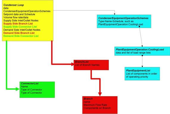
Figure 63. Condenser Loop Input Syntax Map
This alpha field is used as an identifying field for the condenser loop.
This alpha field must be a keyword selected from the list of available fluids for an EnergyPlus plant loop. Either Water or UserDefinedFluidType may be used. If the UserDefinedFluidType keyword is used, the following input field i.e. User Defined Fluid Type must have a value (namely the name of a FluidProperties:GlycolConcentration object).
This alpha field must be specified when the previous field is set to UserDefinedFluidType otherwise it could be left blank. Water, EthyleneGlycol, and PropoleneGlycol are all “built-in” fluids for EnergyPlus (that is, all of the appropriate properties are contained within the program). If the fluid specified here is a mixture of water and ethylene or propylene glycol, then only FluidProperties:GlycolConcentration objects need to be specified and the name of the appropriate one is used here. For another water/glycol mixture, a complete set of fluid property data (FluidProperties:Name and FluidProperties:Temperature objects plus multiple FluidProperties:Concentration objects for specific heat, density, etc.) must be specified (Ref dataset: GlycolPropertiesRefData.idf).
This alpha field is used as an identifying field for the condenser operation scheme. This field ties to the Condenser Operation Schemes input structure, which must also be defined.
This alpha field is used to identify the node which the Loop Manager will access the temperature setpoint that it will try to maintain. This is typically the Condenser Loop Supply Side Outlet Node so that it will not interfere with component temperature setpoints. An associated temperature setpoint manager will need to be defined.
This numeric field contains the maximum allowable temperature in Celsius for this loop.
This numeric field contains the minimum allowable temperature in Celsius for this loop. This minimum loop temperature is used by the cooling towers to make sure that the minimum is not violated to keep the equipment safe. The minimum is also used to trigger the minimum temperature warning and will notify the user if it gets too low.
This numeric field contains the maximum loop flow rate in cubic meters per second. This field is autosizable.
This numeric field contains the minimum loop flow rate in cubic meters per second.
Volume of the condenser loop in m3. This numeric field contains the loop volume for the entire loop, i.e., both the demand side and the supply side. This is used for the loop capacitance calculation. Loop volume (m3) could be calculated from pipe size data but this is not usually known. If zero volume is specified the loop has no fluid heat capacity. If a very large capacitance is specified unrealistic time delay may result and there may be poor response to changes in loop setpoint temperature. The loop capacitance autocalculate option gives reasonable values for most system sizes. This calculation is described in the Engineering Reference manual.
This required alpha field contains the identifying name given to the Condenser Side Inlet Node. This node is the inlet to the supply side of the loop.
This required alpha field contains the identifying name given to the Condenser Side Outlet Node. This node is the outlet of the supply side of the loop.
This required alpha field contains the identifying name given to the Condenser Side Branch List. The list referenced here should list all the branches on the supply side of the loop.
This required alpha field contains the identifying name given to the Condenser Side Connector List. The list referenced here should list the splitter and mixer on the supply side of the loop.
This required alpha field contains the identifying name given to the Demand Side Inlet Node. This node is the inlet to the demand side of the loop.
This required alpha field contains the identifying name given to the Demand Side Outlet Node. This node is the outlet of the demand side of the loop.
This required alpha field contains the identifying name given to the Demand Side Branch List. The list referenced here should list all the branches on the demand side of the loop.
This required alpha field contains the identifying name given to the Demand Side Connector List. The list referenced here should list the splitter and mixer on the demand side of the loop.
This alpha field contains the Load Distribution Scheme Keyword. The Load Distribution Scheme selects the algorithm used to sequence equipment operation in order to meet the plant loop demand. Currently, two schemes are functional. Sequential uses each piece of equipment to its maximum part load ratio and will operate the last required piece of equipment between its minimum and maximum part load ratio in order to meet the loop demand. Optimal operates each piece of equipment at its optimal part load ratio and will operate the last component between its minimum and maximum part load ratio in order to meet the loop demand.
This field lets user to choose if this plant loop will be involved in a pressure drop calculation. This requires that at least one branch on the loop have pressure drop data. If not, an error will be thrown due to the input mismatch. Currently there are two pressure drop simulation types: “PumpPowerCorrection” and “LoopFlowCorrection”. In both of these methods, branch pressure drop data is used to calculate a dynamic loop pressure drop and is used to update pumping power accordingly. The flow correction method allows the user to enter information regarding the pressure curve of a constant speed pump so that the simulation can dynamically resolve the pressure vs. flow relationship in the plant loop. This is limited to constant speed pumps, as the variable speed pumps are expected to resolve as if it were controlled by a variable drive, so that they can inherently meet any pressure and flow demand required by the loop. This is also limited to “loop pumps”, where there is a single pump on the plant loop. Common pipe simulations and “branch pump” simulations are not compatible with this level of pressure simulation. See the documentation for the Pump:ConstantSpeed in order to determine required inputs for this pressure simulation method to be performed. In the pressure drop system, parallel flow rates are not resolved (to match the pressure drop for the parallel system). Enhancements to this calculation are planned which will allow parallel branch flow resolution. See the Engineering Reference document for more information on how this works.
An example of this statement used in an IDF is:
CondenserLoop,
Condenser Water Loop, !- Name
Water, !- Fluid Type
, !- User Defined Fluid Type
Tower Loop Operation, !- Condenser Equipment Operation Scheme Name
Condenser Supply Outlet Node, !- Condenser Loop Temperature Setpoint Node Name
80, !- Maximum Loop Temperature {C}
10, !- Minimum Loop Temperature {C}
autosize, !- Maximum Loop Flow Rate {m3/s}
0.0, !- Minimum Loop Flow Rate {m3/s}
autocalculate, !- Condenser Loop Volume {m3}
Condenser Supply Inlet Node, !- Condenser Side Inlet Node Name
Condenser Supply Outlet Node, !- Condenser Side Outlet Node Name
Condenser Supply Side Branches, !- Condenser Side Branch List Name
Condenser Supply Side Connectors, !- Condenser Side Connector List Name
Condenser Demand Inlet Node, !- Demand Side Inlet Node Name
Condenser Demand Outlet Node, !- Demand Side Outlet Node Name
Condenser Demand Side Branches, !- Condenser Demand Side Branch List Name
Condenser Demand Side Connectors, !- Condenser Demand Side Connector List Name
Sequential; !- Load Distribution Scheme
SetpointManager:FollowOutdoorAirTemperature,
MyCondenserControl, !- Name
Temperature, !- Control Variable
OutdoorAirWetBulb, !- Reference Temperature Type
0, !- Offset Temperature Difference {deltaC}
80, !- Maximum Setpoint Temperature {C}
10, !- Minimum Setpoint Temperature {C}
Condenser Supply Outlet Node; !- Setpoint Node or NodeList Name
CondenserLoop,
Chilled Water Condenser Loop, !- Name
UserDefinedFluidType, !- Fluid Type
PropyleneGlycol15Percent,!- User Defined Fluid Type
Tower Loop Operation, !- Condenser Equipment Operation Scheme Name
Condenser Supply Outlet Node, !- Condenser Loop Temperature Setpoint Node Name
80, !- Maximum Loop Temperature {C}
10, !- Minimum Loop Temperature {C}
0.00330000, !- Maximum Loop Flow Rate {m3/s}
0, !- Minimum Loop Flow Rate {m3/s}
autocalculate, !- Condenser Loop Volume {m3}
Condenser Supply Inlet Node, !- Condenser Side Inlet Node Name
Condenser Supply Outlet Node, !- Condenser Side Outlet Node Name
Condenser Supply Side Branches, !- Condenser Side Branch List Name
Condenser Supply Side Connectors, !- Condenser Side Connector List Name
Condenser Demand Inlet Node, !- Demand Side Inlet Node Name
Condenser Demand Outlet Node, !- Demand Side Outlet Node Name
Condenser Demand Side Branches, !- Condenser Demand Side Branch List Name
Condenser Demand Side Connectors, !- Condenser Demand Side Connector List Name
Sequential; !- Load Distribution Scheme
HVAC,Average,Cond Loop Cooling Demand [W]
HVAC,Average,Cond Loop Heating Demand [W]
HVAC,Average,Cond Loop InletNode Flowrate [kg/s]
HVAC,Average,Cond Loop Inlet Temp [C]
HVAC,Average,Cond Loop Outlet Temp [C]
HVAC,Average,Cond Loop Demand Not Distributed [W]
HVAC,Average,Cond Loop Unmet Demand [W]
HVAC,Average,Cond Loop Demand Side Pressure Drop [Pa]
HVAC,Average,Cond Loop Supply Side Pressure Drop [Pa]
HVAC,Average,Cond Loop Pressure Drop [Pa]
This is the value of the net demand required to meet the cooling setpoint of the loop. If the loop setpoint is met for the current HVAC timestep, Cond Loop Cooling Demand will equal sum of the total cooling demand from the demand side components on the loop (typically condenser coils of chillers, etc.). It will also equal the cooling output of all condensing equipment such as cooling towers on the loop less any pump heat added to the fluid. For example, for a condenser loop with one tower and one pump serving one chiller, Cond Loop Cooling Demand will equal the tower water-side heat transfer less the pump heat to fluid, and it will also equal the chiller condenser heat transfer rate.
If the condenser loop setpoint is not met, Cond Loop Cooling Demand will equal the sum of the total cooling demand from the demand side components on the loop plus the additional cooling required to bring the loop flow to setpoint. If the loop remains off setpoint for successive timesteps, the demand required to return to setpoint will repeat in each timestep until the loop reaches setpoint. For this reason, Cond Loop Cooling Demand should not be summed over time, because it will overstate the demand whenever the loop is off setpoint.
This is the value of the net demand required to meet the heating setpoint of the loop. If the loop setpoint is met for the current HVAC timestep, Cond Loop Heating Demand will equal sum of the total heating demand from the demand side components on the loop. It will also equal the heating output of all heating equipment on the supply side of the loop plus any pump heat added to the fluid. For example, for a condenser loop with one ground loop heat exchanger and one pump serving one water-to-water heat pump, Cond Loop Heating Demand will equal the ground loop heat transfer plus the pump heat to fluid, and it will also equal the heat pump condenser side heat transfer rate.
This is the value of the mass flow rate at the Inlet to Condenser Loop on the supply side. There is not an associated Condenser Loop outlet node flow rate since continuity must be maintained in the loop and the outlet must be the same.
This is the value of the temperature at the Inlet to the condenser loop on the supply side.
This is the value of the temperature at the outlet to the condenser loop on the supply side.
This is the value of the demand that could not be distributed to the condenser equipment because of some constraint in the operation scheme. This is a record of the loop operation scheme supervisory controls after attempting to distribute the load. For example it would be non-zero in situations where the load is larger than the upper limit of capacities set for the condenser equipment controls. This output is for before the equipment has actually been simulated whereas the separate output Cond Loop Unmet Demand is for after the equipment has simulated.
This is the value of the demand NOT provided by the condenser equipment to meet the heating or cooling setpoint of the loop. The value is positive when the condenser equipment cannot meet the setpoint, and the value is negative when the condenser equipment provides more than enough heating or cooling to meet the setpoint. A negative value can happen when the amount of demand is smaller than the minimum capacity of the equipment using the minimum part load ratio.
This field is the demand side pressure drop of a condenser loop. This output is only recognized if a valid pressure simulation is being performed. To do this, the user must specify a pressure simulation type as an input in the CondenserLoop object, and input at least one pressure drop curve on a branch of the plant/condenser loop. This particular output is only relevant if the user puts that curve on the demand side of the loop.
This field is the supply side pressure drop of a condenser loop. This output is only recognized if a valid pressure simulation is being performed. To do this, the user must specify a pressure simulation type as an input in the CondenserLoop object, and input at least one pressure drop curve on a branch of the plant/condenser loop. This particular output is only relevant if the user puts that curve on the supply side of the loop.
This field is the total pressure drop of a condenser loop. This output is only recognized if a valid pressure simulation is being performed. To do this, the user must specify a pressure simulation type as an input in the CondenserLoop object, and input at least one pressure drop curve on a branch of the plant/condenser loop. This particular output is relevant regardless of the location of pressure drop curves: demand side, supply side, or both.
Plants and condenser loops must have some mechanism for controlling the operation of the loop and which equipment is available under what conditions. Since there may be multiple control schemes that are assigned various priorities associated with each loop, an overall operation scheme must be defined. The overall scheme consists of the object name, an identifying name that is referenced in the main plant or condenser loop statement, and a list of operation schemes. Each operation scheme must have the type of operation scheme, its identifying name, and the schedule that defines its availability. Note that the order in which the individual operation schemes appear in this list defines its priority versus the others with the same scheduled availability. The first scheme appearing in the list is given the highest priority, the second scheme has second highest priority, etc. In other words, if according to its schedule, the first operation scheme is available, then it is used by the simulation to define how the plant or condenser loop operates. If it is not available, the second operation scheme in the list is checked to see if it is available until the highest priority scheme that is also available is found. To allow for simultaneous heating and cooling, there is one configuration where multiple operation schemes are available at a given timestep. This is allowed if a user inputs both a heating range based operation and a cooling range based operation with overlapping schedules. The simulation will look at the current loop demand to determine if the cooling scheme should be used or the heating scheme. In other cases, if two schemes overlap (are available at the same time), a fatal error will be encountered.
This alpha field contains the identifying name given to the Plant Operation Scheme. This name is placed in the Plant Loop object to select this scheme.
Operation schemes are listed in "priority" order. Note that each scheme must address the entire load and/or condition ranges for the simulation. The actual one selected for use will be the first that is "Scheduled" on. That is, if control scheme 1 is not "on" and control scheme 2 is -- then control scheme 2 is selected. Only plant equipment should be listed on a Control Scheme for this item.
This alpha field contains the keyword for the type of control scheme used. The options for plant control schemes are:
n PlantEquipmentOperation:Uncontrolled
n PlantEquipmentOperation:CoolingLoad
n PlantEquipmentOperation:HeatingLoad
n PlantEquipmentOperation:ComponentSetpoint
This alpha field contains the identifying name given to the control scheme. These must be the named versions of the referenced Control Scheme (e.g.. a Uncontrolled Loop Operation with this name or a Cooling or Heating Load Range Based Operation with this name).
This alpha field contains the schedule name for the control scheme. This schedule consists of weeks and days, with the days containing “0 or 1” for each hour of the day. This binary schedule (0 for off, 1 for on) determines if the control scheme is operating for that hour of day or not.
Examples of this statement in two different IDFs:
PlantEquipmentOperationSchemes,
CW Loop Operation, !- Name
PlantEquipmentOperation:CoolingLoad, ! Control Scheme 1 Object Type
Peak Operation, !- Control Scheme 1 Name
On Peak, !- Control Scheme 1 Schedule
PlantEquipmentOperation:CoolingLoad, ! Control Scheme 2 Object Type
Off Peak Operation, !- Control Scheme 2 Name
Off Peak; !- Control Scheme 2 Schedule
PlantEquipmentOperationSchemes,
CW Loop Operation, !- Name
PlantEquipmentOperation:CoolingLoad, ! Control Scheme 1 Object Type
Central Chiller Only, !- Control Scheme 1 Name
PlantOnSched; !- Control Scheme 1 Schedule
In the first IDF example, “PlantEquipmentOperation:CoolingLoad” is the type of control scheme. “Peak Operation” and “Off Peak Operation” are the names of two different load range based controls defined separately (see below -- ). “On Peak” and “Off Peak” are schedules defined elsewhere in the input file.
The load range based operation scheme has two statements associated with it: a main statement that defines the ranges that individual priority settings are valid and the lists of equipment that may be used for each range.
This alpha field contains the identifying name given to the Condenser Operation Scheme.
Operation schemes are listed in "priority" order. Note that each scheme must address the entire load and/or condition ranges for the simulation. The actual one selected for use will be the first that is "Scheduled" on. That is, if control scheme 1 is not "on" and control scheme 2 is -- then control scheme 2 is selected. Only condenser equipment should be listed on a Control Scheme for this item.
This alpha field contains the keyword for the type of control scheme used. The options for plant control schemes are:
This alpha field contains the keyword for the type of control scheme used. Currently, the available options are:
n PlantEquipmentOperation:Uncontrolled
n PlantEquipmentOperation:CoolingLoad
n PlantEquipmentOperation:HeatingLoad
n PlantEquipmentOperation:OutdoorDryBulb
n PlantEquipmentOperation:OutdoorWetBulb
n PlantEquipmentOperation:OutdoorDewpoint
n PlantEquipmentOperation:OutdoorRelativeHumidity
n PlantEquipmentOperation:OutdoorDryBulbDifference
n PlantEquipmentOperation:OutdoorWetBulbDifference
n PlantEquipmentOperation:OutdoorDewpointDifference
The condenser operation schemes apply to the equipment on the ‘supply side’ of the condenser loop—pumps, cooling towers, ground coupled heat exchangers, etc. The keywords select the algorithm that will be used to determine which equipment is available for each timestep. The Load Schemes schemes select a user specified set of equipment for each user specified range of a particular simulation variable. Load schemes compare the demand on the condenser supply side with specified load ranges and associated equipment lists. Outdoor schemes compare the current value of an environmental parameter with user specified ranges of that parameter.
This alpha field contains the identifying name given to the control scheme.
This alpha field contains the schedule name for the control scheme. This schedule consists of weeks and days, with the days containing “0 or 1” for each hour of the day. This binary schedule (0 for off, 1 for on) determines which control scheme is operating for a particular hour. The schedule facilitates daily or seasonal changes in control schemes to meet demand side management or energy conservation goals.
Scheduling conflicts are handled by selecting the first available scheme in order of appearance in the list.
Examples of this statement in two IDFs:
CondenserEquipmentOperationSchemes,
Tower Loop Operation, !- CondenserOperationSchemeName
PlantEquipmentOperation:CoolingLoad, Control Scheme 1 Object Type
Year Round Tower Operation, !- Control Scheme 1 Name
PlantOnSched; !- Control Scheme 1 Schedule
CondenserEquipmentOperationSchemes,Tower Loop Operation,
PlantEquipmentOperation:CoolingLoad, Peak Load Operation, AFTERNOONSCHEDULE,
PlantEquipmentOperation:CoolingLoad, OffPeak Load Operation, MORNINGSCHEDULE,
PlantEquipmentOperation:OutdoorWetBulb, NightOperation, NIGHTSCHEDULE;
Each schedule (AFTERNOONSCHEDULE, MORNINGSCHEDULE, NIGHTSCHEDULE) invokes its associated operation scheme (Peak Load Operation, OffPeak Load Operation, NightOperation). The type of operation scheme and its name references the input syntax associated with the range specification and the associated equipment.
Uncontrolled loop operation simply specifies a group of equipment that runs ‘uncontrolled’. If the loop runs, this equipment will run also, unless turned off by the loop flow resolver to maintain continuity in the fluid loop.
This alpha field contains the identifying name for the control scheme.
This alpha field contains the identifying name for the Equipment List. This field ties to the Load Range Equipment List input structure, which must also be defined.
This alpha field contains the identifying name for the Equipment List. This field ties to the PlantEquipmentList or CondenserEquipmentList input structure, which must also be defined.
The PlantEquipmentOperation:CoolingLoad and PlantEquipmentOperation:HeatingLoad objects define the different ranges and which equipment list is valid for each range. After the keyword and the identifying name, a series of data trios is expected. In each trio, there is a lower limit for the load range, an upper limit for the load range, and a name that links to an equipment availability list (the PlantEquipmentList or CondenserEquipmentList objects).
This alpha field contains the identifying name for the control scheme.
This numeric field contains the lower demand range (W) for the equipment list. If demand is below this value, then this equipment list will not turn on to meet the demand.
This numeric field contains the upper demand range (W) for the equipment list. If demand is above this value, then this equipment list will not turn on to meet the demand.
This alpha field contains the identifying name for the Equipment List (i.e., the name of a PlantEquipmentList or CondenserEquipmentList object).
An example of these statements in an IDF is:
PlantEquipmentOperation:CoolingLoad, Peak Operation,
0,7000, Chiller Plant,
7000,24500, Chiller Plant and Purchased,
24500,500000, Purchased Only;
This particular load based operation scheme (above) has three different ranges. “Chiller Plant”, “Chiller Plant and Purchased”, and “Purchased Only” are names which link to various PlantEquipmentList or CondenserEquipmentList objects as described below. Gaps may be left in the load ranges specified, but to operate equipment over the entire range the upper limit of a given range must equal the lower limit of the next range as shown in the example. If gaps are left in the load ranges specified, a warning message will be issued when the load to be met falls within a load range “gap”. If the user wishes to leave a load range “gap” for a specific reason (no equipment to operate on this plant [or condenser] loop within this load range) and does not want the warning messages to be generated, then specify a lower limit, upper limit and equipment list name for the gap and do not specify any equipment in the associated equipment list, as shown below.
PlantEquipmentOperation:CoolingLoad, Peak Operation,
0,7000, Chiller Plant,
7000,7100, NoEquipmentOperationOnThisPlantLoop,
7100,24500, Chiller Plant and Purchased,
24500,500000, Purchased Only;
PlantEquipmentList,
Chiller Plant, !- Name
Chiller:Electric, !- Equipment 1 Object Type
Big Chiller; !- Equipment 1 Name
PlantEquipmentList,
NoEquipmentOperationOnThisPlantLoop; !- Name
PlantEquipmentList,
Chiller Plant and Purchased, !- Name
Chiller:Electric, !- Equipment 1 Object Type
Big Chiller, !- Equipment 1 Name
DistrictCooling, !- Equipment 2 Object Type
Purchased Cooling; !- Equipment 2 Name
PlantEquipmentList,
Purchased Only, !- Name
DistrictCooling, !- Equipment 1 Object Type
Purchased Cooling; !- Equipment 1 Name
The outdoor operation objects define the different ranges of the various environmental parameters and which equipment list is valid for each range. After the keyword and the identifying name, a series of data trios is expected. In each trio, there is a lower limit for the load range, an upper limit for the load range, and a name that links to an equipment availability list (the CondenserEquipmentList).
The fields for each of these are:
This alpha field contains the identifying name for the control scheme.
This numeric field contains the lower limit (C for temperature operations, Percent for relative humidity operations) for the equipment list. If specific value is below this value, then this equipment list will not turn on to meet the demand.
This numeric field contains the lower limit (C for temperature operations, Percent for relative humidity operations) for the equipment list. If specific value is above this value, then this equipment list will not turn on to meet the demand.
This alpha field contains the identifying name for the Equipment List (i.e., the name of a CondenserEquipmentList object).
The Delta Temperature based control strategies help to control any condenser equipment based on the difference between a reference node temperature and any environmental temperature. For example a cooling tower can be controlled by a strategy, which looks at the difference between the tower inlet temperature and wet-bulb temperature. A difference range is specified for each equipment list. IDD excerpts are shown below:
This alpha value contains the identifying name of the control strategy. This name appears as ‘control scheme name’ in Condenser Operation Scheme object.
This alpha value specifies the reference node for the operation scheme identified in the first field.
This numeric field specifies the minimum temperature difference required for the equipment specified in the equipment list to operate.
This numeric field specifies the maximum temperature difference below which the equipment specified in the equipment list is available.
This alpha field contains the identifying name for the Equipment List (i.e., the name of a CondenserEquipmentList object).
In addition to load range based control on the plant loop, sequencing the plant components based on the outlet temperature of individual equipment is allowed. This scheme is common to many present-day Energy Management Systems sequencing. In this scheme, the sequencing is done based on the order specified in the control object described below.
This field specifies the name of the operation scheme.
This field specifies the type of equipment controlled by scheme.
This field specifies the name of the controlled equipment.
The component demand will be calculated using the difference between the temperature at the demand node and the component set point temperature.
Each component controlled under temperature based control will have its own set point different from the loop set point. This field specifies component set point node (Generally its outlet temperatures). This node is acted upon by a SetpointManager in order to obtain the setpoint at any simulation timestep.
This numeric field specifies the design flow rate for the component specified in earlier fields. This flow rate is used to calculate the component demand. The field can be set to autosize, if the user wants the program to calculate the design flow. This would generally be set to autosize when the user does not know the component flow rate and does a sizing calculation for the corresponding component.
This alpha field specifies the operation mode for the equipment. The equipment can be in any of the three modes viz. Cooling, Heating and Dual. Dual is used when the components both as heating and cooling equipment (for example heat pumps).
And, as an example in an IDF:
PlantEquipmentOperationSchemes,
CW Loop Operation, !- PlantOperationSchemeName
PlantEquipmentOperation:ComponentSetpoint, ! Control Scheme 1 Object Type
Test Scheme, !- Control Scheme 1 Name
On; !- Control Scheme 1 Schedule
PlantEquipmentOperation:ComponentSetpoint,
Test Scheme,
CHILLER:ELECTRIC, !- Equipment 1 Object Type
Little Chiller, !- Equipment 1 Name
Little Chiller Inlet Node, !- Demand Calculation 1 Node Name
Little Chiller Outlet Node, !- Setpoint 1 Node Name
0.0011, !- Component 1 Flow Rate
COOLING, !- Operation 1 Type
CHILLER:ELECTRIC, !- Equipment 2 Object Type
Big Chiller, !- Equipment 2 Name
Big Chiller Inlet Node, !- Demand Calculation 2 Node Name
Big Chiller Outlet Node, !- Setpoint 2 Node Name
0.0011, !- Component 2 Flow Rate
COOLING; !- Operation 2 Type
The PlantEquipmentList and CondenserEquipmentList specify available plant and condenser loop equipment respectively for any loop operation scheme. Each statement contains the object name, an identifying name (which links the definition back to one of the operation scheme statements) and a variable length of data pairs. These pairs refer to a plant equipment type and an identifying name. The type in this list of pairs must correspond to a valid plant object as described in the next subsection.
Note: If a PlantEquipmentList or CondenserEquipmentList object is specified with no equipment object types or equipment names, then the corresponding PlantEquipmentOperation:* object will assume all available equipment on this plant (or condenser) loop should be OFF (not operate) within the specified lower/upper limit.
This alpha field contains the identifying name for the Equipment List.
Remember the order of equipment on this list determines operation priority. Equipment on the list first will try to meet demand first. These fields tie to the Equipment Definition input structure, which must also be defined.
This alpha field contains the keyword for the type of equipment in operation. Example: (Chiller:Electric, DistrictCooling). The full list of allowable plant equipment is valid plant objects as described in the next subsection.
This alpha field contains the identifying name for the equipment in operation. This distinguishes between two different pieces of equipment of the same type.
An example of this statement in an IDF is:
PlantEquipmentList, Chiller Plant and Purchased,
Chiller:Electric, Big Chiller,
DistrictCooling, Purchased Cooling;
Note that this list is the middle range defined in the PlantEquipmentOperation:CoolingLoad statement named “Peak Operation” above. This defines the equipment available when the load encountered by the plant (chiller water demand, for example) is between 7000 W and 24500 W. EnergyPlus will run the “Big Chiller” first up to its capacity and then attempt to meet the remaining load (while in that range) with the next piece of equipment (in this case, “Purchased:Cooling”) in the list.
In each PlantEquipmentList described using the above syntax, various equipment types and names must be given. Each type-name pair must then have a corresponding equipment definition. This subsection lists the various equipment types that are available and examples from an IDF. Where appropriate, notes and comments on the input structure are provided.
Many output variable names are common across all chiller types. These generic chiller output names all begin with the word "Chiller". Certain chiller types have additional output variables which are specific to that type of chiller. Specific chiller output names begin with the chiller type, for example, "Gas Absorption Chiller Heating Energy [J]." Chiller energy use is added to the appropriate plant-level meters as a cooling end-use.
HVAC,Average,Chiller Electric Power [W]
HVAC,Sum,Chiller Electric Consumption [J]
Zone,Meter,Electricity:Plant [J]
Zone,Meter,Cooling:Electricity [J]
HVAC,Average,Chiller Evap Heat Trans Rate [W]
HVAC,Sum,Chiller Evap Heat Trans [J]
Zone,Meter,EnergyTransfer:Plant [J]
Zone,Meter,Chillers:EnergyTransfer [J]
HVAC,Average,Chiller Evap Water Inlet Temp [C]
HVAC,Average,Chiller Evap Water Outlet Temp [C]
HVAC,Average,Chiller Evap Water Mass Flow Rate [kg/s]
HVAC,Average,Chiller Cond Heat Trans Rate [W]
HVAC,Sum,Chiller Cond Heat Trans [J]
Zone,Meter,HeatRejection:EnergyTransfer [J]
HVAC,Average,Chiller COP [W/W]
The following output is applicable only for air-cooled or evap-cooled chillers
HVAC,Average,Chiller Cond Air Inlet Temp [C]
The following outputs are applicable only for evap-cooled chillers
HVAC,Average,Chiller Basin Heater Electric Power [W]
HVAC,Average,Chiller Basin Heater Electric Consumption [J]
The following three outputs are only available for water-cooled chillers
HVAC,Average,Chiller Cond Water Inlet Temp [C]
HVAC,Average,Chiller Cond Water Outlet Temp [C]
HVAC,Average,Chiller Cond Water Mass Flow Rate [kg/s]
HVAC,Average,Chiller Shaft Power [W]
HVAC,Sum,Chiller Shaft Energy [J]
Zone,Meter,HeatRecovery:EnergyTransfer [J]
HVAC,Average,Chiller Lube Heat Recovery Rate [W]
HVAC,Sum,Chiller Lube Heat Recovery [J]
HVAC,Average,Chiller Jacket Heat Recovery Rate [W]
HVAC,Sum,Chiller Jacket Heat Recovery [J]
HVAC,Average,Chiller Exhaust Heat Recovery Rate [W]
HVAC,Sum,Chiller Exhaust Heat Recovery [J]
HVAC,Average,Chiller Total Heat Recovery Rate [W]
HVAC,Sum,Chiller Total Heat Recovery [J]
HVAC,Average,Chiller Exhaust Stack Temp[C]
HVAC,Average,Chiller Heat Recovery Inlet Temp [C]
HVAC,Average,Chiller Heat Recovery Outlet Temp [C]
HVAC,Average,Chiller Heat Recovery Mass Flow Rate [kg/s]
The following blocks of outputs are for steam and fuel-driven chillers
HVAC,Average,Chiller Gas Consumption Rate [W]
HVAC,Sum,Chiller Gas Consumption [J]
Zone,Meter,Gas:Plant [J]
Zone,Meter,Cooling:Gas [J]
HVAC,Average,Chiller Gas Mass Flow Rate [kg/s]
HVAC,Sum,Chiller Gas Mass Consumption [kg]
For steam absorption chillers:
HVAC,Average,Chiller Steam Consumption Rate [W]
HVAC,Sum,Chiller Steam Consumption [J]
Zone,Meter,Steam:Plant [J]
Zone,Meter,Cooling:Steam [J]
HVAC,Average,Chiller Steam Mass Flow Rate [kg/s]
For hot water absorption chillers:
HVAC,Average,Chiller How Water Consumption Rate [W]
HVAC,Sum,Chiller Hot Water Consumption [J]
Zone,Meter,Steam:Plant [J]
Zone,Meter,Cooling:EnergyTransfer [J]
HVAC,Average,Chiller Hot Water Mass Flow Rate [kg/s]
The following output is applicable only for indirect absorption chillers HVAC,Average,Chiller Part-Load Ratio
HVAC,Average,Chiller Cycling Fraction
HVAC,Average,Chiller Propane Consumption Rate [W]
HVAC,Sum,Chiller Propane Consumption [J]
Zone,Meter,Propane:Plant [J]
Zone,Meter,Cooling:Propane [J]
HVAC,Average,Chiller Propane Mass Flow Rate [kg/s]
HVAC,Average,Chiller Diesel Consumption Rate [W]
HVAC,Sum,Chiller Diesel Consumption [J]
Zone,Meter,Diesel:Plant [J]
Zone,Meter,Cooling:Diesel [J]
HVAC,Average,Chiller Diesel Mass Flow Rate [kg/s]
HVAC,Average,Chiller Gasoline Consumption Rate [W]
HVAC,Sum,Chiller Gasoline Consumption [J]
Zone,Meter,Gasoline:Plant [J]
Zone,Meter,Cooling:Gasoline [J]
HVAC,Average,Chiller Gasoline Mass Flow Rate [kg/s]
HVAC,Average,Chiller FuelOil#1 Consumption Rate [W]
HVAC,Sum,Chiller FuelOil#1 Consumption [J]
Zone,Meter,FuelOil#1:Plant [J]
Zone,Meter,Cooling:FuelOil#1 [J]
HVAC,Average,Chiller FuelOil#1 Mass Flow Rate [kg/s]
HVAC,Average,Chiller FuelOil#2 Consumption Rate [W]
HVAC,Sum,Chiller FuelOil#2 Consumption [J]
Zone,Meter,FuelOil#2:Plant [J]
Zone,Meter,Cooling:FuelOil#2 [J]
HVAC,Average,Chiller FuelOil#2 Mass Flow Rate [kg/s]
These outputs are the electric power input to the chiller. In the case of steam or fuel-powered chillers, this repesents the internal chiller pumps and other electric power consumption. Consumption is metered on Cooling:Electricity, Electricity:Plant, and Electricity:Facility.
These outputs are the evaporator heat transfer which is the cooling delivered by the chiller. Chiller Evap Heat Trans is metered on Chillers:EnergyTransfer, EnergyTransfer:Plant, and EnergyTransfer:Facility.
These outputs are the evaporator (chilled water) inlet and outlet temperatures and flow rate.
This output is the coefficient of performance for the chiller during cooling operation. It is calculated as the evaporator heat transfer rate (Chiller Evap Heat Trans Rate) divided by the “fuel” consumption rate by the chiller. For the constant COP and electric chillers, the “fuel” is electricity so the divisor is Chiller Electric Power [W]. For the absorption chiller, the “fuel” is steam so the divisor is Steam Consumption Rate [W].
For the engine driven chiller and combustion turbine chiller, the output variable is renamed as Chiller Fuel COP to clarify that the primary energy input to the chiller is a gaseous or liquid fuel (natural gas, diesel, gasoline, etc.). The divisor is the appropriate fuel consumption rate (Chiller [fuel type] Consumption Rate).
For the direct fired absorption chiller, this variable is renamed as Direct Fired Absorption Chiller Cooling Fuel COP and the divisor is Direct Fired Absorption Chiller Cooling Gas Consumption Rate.
Note that this variable is reported as zero when the chiller is not operating. When reported for frequencies longer than "detailed" (such as timestep, hourly, daily, monthly or environment), this output will only be meaningful when the chiller is operating for the entire reporting period. To determine an average COP for a longer time period, compute the COP based on total evaporator heat transfer divided by total electric or fuel input over the desired period.
This output is the operating part-load ratio of the indirect absorption chiller. This output may fall below the minimum part-load ratio specified in the input. For this case, the Chiller Cycling Fraction is used to further define the performance of the indirect absorption chiller.
This output is the fraction of the timestep the indirect absorption chiller operates. When the chiller operates above the minimum part-load ratio, a chiller cycling fraction of 1 is reported. When the chiller operates below the minimum part-load ratio, the chiller cycling fraction reports the fraction of the timestep the indirect absorption chiller operates.
These outputs are the condenser heat transfer which is the heat rejected from the chiller to either a condenser water loop or through an air-cooled condenser. Chiller Cond Heat Trans is metered on HeatRejection:EnergyTransfer, EnergyTransfer:Plant, and EnergyTransfer:Facility.
This output is the condenser (heat rejection) inlet temperature for air-cooled or evap-cooled chillers. For an air-cooled chiller, this output would be the dry-bulb temperature of the air entering the condenser coil. For an evap-cooled chiller, this output would be the wet-bulb temperature of the air entering the evaporatively-cooled condenser coil.
These outputs are the electric power input to the chiller’s basin heater (for evaporatively-cooled condenser type). Consumption is metered on Chillers:Electricity, Electricity:Plant, and Electricity:Facility
These outputs are the condenser (heat rejection) inlet and outlet temperatures and flow rate for water-cooled chillers.
For engine-driven and turbine-driven chillers, these outputs are the shaft power produced by the prime mover and transferred to the chiller compressor.
For chillers with heat recovery, such as engine-driven chillers, these outputs are the components of recoverable energy available. For a given chiller type, one or more of the following components may be applicable: Lube (engine lubricant), Jacket (engine coolant), Exhaust (engine exhaust), and Total. Chiller Lube Heat Recovery, Chiller Jacket Heat Recovery, and Chiller Exhaust Heat Recovery are metered on HeatRecovery:EnergyTransfer, EnergyTransfer:Plant, and EnergyTransfer:Facility.
This is the exhaust temperature leaving an engine chiller.
These outputs are the heat recovery inlet and outlet temperatures and flow rate for chillers with heat recovery such as engine-driven and gas turbine chillers.
These outputs are the steam or fuel input for steam or fuel-fired chillers. Valid fuel types depend on the type of chiller. <FuelType> may be one of: Gas (natural gas), Steam, Propane, Diesel, Gasoline, FuelOil#1, and FuelOil#2. Consumption is metered on Cooling:<FuelType>, <FuelType>:Plant, and <FuelType>:Facility.
This alpha field contains the identifying name for the absorption chiller.
This numeric field contains the nominal cooling capability of the chiller in Watts.
This numeric field contains the nominal pumping power of the absorber in Watts.
This required alpha field contains the identifying name for the absorption chiller plant side inlet node.
This required alpha field contains the identifying name for the absorption chiller plant side outlet node.
This required alpha field contains the identifying name for the absorption chiller condenser side inlet node.
This required alpha field contains the identifying name given to the Heat Recovery Loop Component Outlet Node.
This numeric field contains the absorption chiller’s minimum part load ratio. The expected range is between 0 and 1. The minimum part load is not the load where the machine shuts off, but where the amount of power remains constant to produce smaller loads than this fraction.
This numeric field contains the absorption chiller’s maximum part load ratio. This value may exceed 1, but the normal range is between 0 and 1.1.
This numeric field contains the absorption chiller’s optimum part load ratio. This is the part load ratio at which the chiller performs at its maximum COP.
This numeric field contains the absorption chiller’s condenser inlet design temperature in Celsius.
For variable volume chiller this is the maximum flow and for constant flow chiller this is the design flow rate. The units are in cubic meters per second.
This numeric field contains the absorption chiller’s design condenser water flow rate in cubic meters per second.
The Generator Heat Input Part Load Ratio Curve is a quadratic equation that determines the Ratio of the generator load on the absorber to the demand on the chiller. The defining equation is:
![]()
The following three fields contain the coefficients for the equation.
C1 in the Generator Heat Input Part Load Ratio Curve. This value is obtained by fitting manufacturers’ performance data to the curve.
C2 in the Generator Heat Input Part Load Ratio Curve. This value is obtained by fitting manufacturers’ performance data to the curve.
C3 in the Generator Heat Input Part Load Ratio Curve. This value is obtained by fitting manufacturers’ performance data to the curve.
The Pump Electric Use Part Load Ratio Curve is a quadratic equation that determines the Ratio of the actual absorber pumping power to the nominal pumping power. The defining equation is:
![]()
The following three fields contain the coefficients for the equation.
C1 in the Pump Electric Use Part Load Ratio Curve. This value is obtained by fitting manufacturers’ performance data to the curve.
C2 in the Pump Electric Use Part Load Ratio Curve. This value is obtained by fitting manufacturers’ performance data to the curve.
C3 in the Pump Electric Use Part Load Ratio Curve. This value is obtained by fitting manufacturers’ performance data to the curve.
This numeric field contains the lower limit for the evaporator outlet temperature. This temperature acts as a cut off for heat transfer in the evaporator, so that the fluid doesn’t get too cold.
This alpha field contains the identifying name given to the Generator Inlet Node. A steam or hot water loop is not required to simulate an absorption chiller. If a steam/hot water loop is used, enter the name of the generator inlet node.
This alpha field contains the identifying name given to the Generator Outlet Node. A steam or hot water loop is not required to simulate an absorption chiller. If a steam/hot water loop is used, enter the name of the generator outlet node.
This alpha field determines if the Chiller is either a VariableFlow or ConstantFlow Chiller Simulation. The default, if not specified, is VariableFlow.
This choice field specifies the type of fluid used to heat the generator solution. The valid choices are HotWater or Steam. This field should be specified as Steam or left blank if the generator inlet/outlet nodes are not specified.
This numeric field contains the absorption chiller’s design condenser fluid flow rate in cubic meters per second.
Ideally, the steam trap located at the outlet of the generator should remove all the condensate immediately, however, there is a delay in this process in actual systems which causes the condensate to SubCool by a certain amount before leaving the generator. This amount of subcooling is included in the heat transferred to the solution in the generator. The minimum value is 0º Celsius and default is 5º Celsius. This field is not used when the generator inlet/outlet node are not specified or the generator is connected to a hot water loop.
This optional numeric field allows the user to specify a sizing factor for this component. The sizing factor is used when the component design inputs are autosized: the autosizing calculations are performed as usual and the results are multiplied by the sizing factor. For this component the inputs that would be altered by the sizing factor are: Nominal Capacity, Nominal Pumping Power, Design Chilled Water Flow Rate, Design Condenser Water Flow Rate and Design Generator Fluid Flow Rate. Sizing factor allows the user to size a component to meet part of the design load while continuing to use the autosizing feature.
Following is an example input for an Absorption Chiller.
Chiller:Absorption,
Big Chiller, !- Chiller Name
50000, !- Nominal Capacity {W}
250, !- Nominal Pumping Power {W}
Big Chiller Inlet Node, !- Plant_Side_Inlet_Node
Big Chiller Outlet Node, !- Plant_Side_Outlet_Node
Big Chiller Condenser Inlet Node, !- Condenser_Side_Inlet_Node
Big Chiller Condenser Outlet Node, !- Condenser_Side_Outlet_Node
0.15, !- Minimum Part Load Ratio
1.0, !- Maximum Part Load Ratio
0.65, !- Opt Part Load Ratio
35.0, !- Temp Design Condenser Inlet {C}
0.0011, !- Design Chilled Water Flow Rate {m3/s}
0.0011, !- Design Condenser Water Flow Rate {m3/s}
0.03303, !- Coefficient1 of the steam use part load ratio curve
0.6852, !- Coefficient2 of the steam use part load ratio curve
0.2818, !- Coefficient3 of the steam use part load ratio curve
1.0, !- Coefficient1 of the pump electric use part load ratio curve
0, !- Coefficient2 of the pump electric part load ratio curve
0, !- Coefficient3 of the pump electric use part load ratio curve
5, !- Chilled Water Outlet Temperature Lower Limit {C}
AbsorberSteamInletNode, !- Generator Inlet Node Name
AbsorberSteamOutletNode, !- Generator Outlet Node Name
VariableFlow, !- Chiller Flow Mode
Steam, !- Generator Fluid Type
autosize, !- Design Generator Volumetric Fluid Flow Rate {m3/s}
2.0; !- Degree of Subcooling in Steam Generator {C}
HVAC,Average,Chiller Electric Power [W]
HVAC,Sum,Chiller Electric Consumption [J]
Zone,Meter,Electricity:Plant [J]
Zone,Meter,Cooling:Electricity [J]
HVAC,Average,Chiller Evap Heat Trans Rate [W]
HVAC,Sum,Chiller Evap Heat Trans [J]
Zone,Meter,EnergyTransfer:Plant [J]
Zone,Meter,Chillers:EnergyTransfer [J]
HVAC,Average,Chiller Evap Water Inlet Temp [C]
HVAC,Average,Chiller Evap Water Outlet Temp [C]
HVAC,Average,Chiller Evap Water Mass Flow Rate [kg/s]
HVAC,Average,Chiller Cond Heat Trans Rate [W]
HVAC,Sum,Chiller Cond Heat Trans [J]
Zone,Meter,HeatRejection:EnergyTransfer [J]
HVAC,Average,Chiller Cond Water Inlet Temp [C]
HVAC,Average,Chiller Cond Water Outlet Temp [C]
HVAC,Average,Chiller Cond Water Mass Flow Rate [kg/s]
HVAC,Average,Chiller COP [W/W]
For Chillers with Steam Generators:
HVAC,Average, Chiller Steam Consumption Rate [W]
HVAC,Sum, Chiller Steam Consumption [J]
Zone,Meter,Steam:Plant [J]
Zone,Meter,Cooling:Steam [J]
HVAC,Average,Chiller Steam Mass Flow Rate [kg/s]
For Chillers with Hot Water Generators:
HVAC,Average,Chiller Hot Water Consumption Rate [W]
HVAC,Sum,Chiller Hot Water Consumption [J]
Zone,Meter,EnergyTransfer:Plant [J]
Zone,Meter,Cooling:EnergyTransfer [J]
HVAC,Average,Chiller Hot Water Mass Flow Rate [kg/s]
These chiller output variables are defined above under "Generic Chiller Outputs."
The Chiller:Absorption:Indirect object is an enhanced version of the absorption chiller model found in the Building Loads and System Thermodynamics (BLAST) program. This enhanced model is nearly identical to the existing absorption chiller model (Ref. Chiller:Absorption) with the exceptions that: 1) the enhanced indirect absorption chiller model provides more flexible performance curves and 2) chiller performance now includes the impact of varying evaporator, condenser, and generator temperatures. Since these absorption chiller models are nearly identical (i.e., the performance curves of the enhanced model can be manipulated to produce similar results to the previous model), it is quite probable that the Chiller:Absorption model will be deprecated in a future release of EnergyPlus.
This required alpha field contains the identifying name for the indirect absorption chiller.
This required numeric field contains the nominal cooling capability of the chiller in Watts. This field must be greater than 0 and is autosizable.
This required numeric field contains the nominal pumping power of the chiller in Watts. The minimum value for this field is 0 and is autosizable.
This required alpha field contains the identifying name for the chiller chilled water inlet node.
This required alpha field contains the identifying name for the chiller chilled water outlet node.
This required alpha field contains the identifying name for the chiller condenser inlet node.
This required alpha field contains the identifying name given to the chiller outlet node.
This numeric field contains the chiller’s minimum part-load ratio. The expected range is between 0 and 1. The minimum part load is not the load where the machine shuts off, but where the amount of power remains constant to produce smaller loads than this fraction.
This numeric field contains the chiller’s maximum part-load ratio. This value may exceed 1, but the normal range is between 0 and 1.1.
This numeric field contains the chiller’s optimum part-load ratio. This is the part-load ratio at which the chiller performs at its maximum COP.
This numeric field contains the chiller’s condenser inlet design temperature in Celsius. The default value for this field is 30º C and is only used when the Design Chilled Water Flow Rate is autosized.
This numeric field contains the chiller’s lower limit for the condenser entering water temperature in Celsius. The default value for this field is 15º C. If this limit is exceeded, a warning message will report the incident. No correction to chiller capacity is made for low condenser entering water temperatures.
This numeric field contains the chiller’s lower limit for the evaporator leaving water temperature in Celsius. The default value for this field is 5º C. If this limit is exceeded, a warning message will report the incident. No correction to chiller capacity is made for low evaporator leaving water temperatures.
This numeric input specifies the design evaporator volumetric flow rate in cubic meters per second. The value specified must be greater than 0 or this field is autosizable. For variable volume chiller this is the maximum flow and for constant flow chiller this is the design flow rate.
This numeric field specifies the chiller’s design condenser water flow rate in cubic meters per second. The value specified must be greater than 0 or this field is autosizable.
This choice field determines if the chiller is a VariableFlow or ConstantFlow chiller. The default value is VariableFlow.
This required alpha field specifies the name of the curve used to determine the heat input to the chiller. The curve is a quadratic or cubic curve which characterizes the heat input as a function of chiller part-load ratio. The curve output is multiplied by the chiller’s nominal capacity and operating part-load ratio or minimum part-load ratio, whichever is greater, to determine the amount of heat input required for the given operating conditons.
This alpha field specifies the name of the curve used to determine the pump electrical input to the chiller. The curve is a quadratic or cubic curve which characterizes the pump electrical power as a function of chiller part-load ratio. The curve output is multiplied by the chiller’s nominal pumping power and operating part-load ratio or minimum part-load ratio, whichever is greater, to determine the amount of pumping power required for the given operating conditons.
This alpha field contains the identifying name given to the Generator Inlet Node. A steam or hot water loop is not required to simulate an indirect absorption chiller. If a steam/hot water loop is used, enter the name of the generator inlet node.
This alpha field contains the identifying name given to the Generator Outlet Node. A steam or hot water loop is not required to simulate an indirect absorption chiller. If a steam/hot water loop is used, enter the name of the generator outlet node.
This alpha field specifies the name of a quadratic or cubic curve which correlates the chiller’s evaporator capacity as a function of condenser entering water temperature. This curve is used to correct nominal capacity at off-design condensing temperatures.
This alpha field specifies the name of a quadratic or cubic curve which correlates the chiller’s evaporator capacity as a function of evaporator leaving water temperature. This curve is used to correct nominal capacity at off-design evaporator temperatures.
This alpha field specifies the name of a quadratic or cubic curve which correlates the chiller’s evaporator capacity as a function of generator entering water temperature. This curve is used to correct nominal capacity at off-design evaporator temperatures and is only used when the Generator Fluid Type is specified as Hot Water.
This alpha field specifies the name of a quadratic or cubic curve which correlates the chiller’s heat input as a function of condenser entering water temperature. This curve is used to correct generator heat input at off-design condensing temperatures.
This alpha field specifies the name of a quadratic or cubic curve which correlates the chiller’s heat input as a function of evaporator leaving water temperature. This curve is used to correct generator heat input at off-design evaporator temperatures.
This choice field specifies the type of fluid used to heat the generator solution. The valid choices are HotWater or Steam. This input is used to identify the method used to calculate the generator mass flow rate. This field is not used if the generator inlet/outlet nodes are not specified. The default value is Steam.
This numeric field specifies the chiller’s design generator fluid flow rate in cubic meters per second. The value specified must be greater than 0 or this field is autosizable. For variable flow chillers this is the maximum generator flow rate, for constant flow chillers this is the flow rate.
This numeric field specifies the lower limit of the generator’s entering water temperature. This field is not used iif the Generator Fluid Type is specified as steam.
Ideally the steam trap located at the outlet of generator should remove all the condensate immediately, however there is a delay in this process in actual systems which causes the condensate to SubCool by a certain degree before leaving the generator. This amount of subcooling is included in the heat transferred to the solution in the generator. The minimum value is 0º Celsius, the maximum value is 20º Celsius, and the default is 1º Celsius.
This essentially represents the heat loss to the atmosphere due to uninsulated condensate return piping to the boiler. Condensate return piping operates at atmospheric pressure and is not insulated. The condensate sub cools to certain degree before it is pumped back to the boiler. The minimum value is 0º Celsius and the default is 0º Celsius.
This optional numeric field allows the user to specify a sizing factor for this component. The sizing factor is used when the component design inputs are autosized: the autosizing calculations are performed as usual and the results are multiplied by the sizing factor. For this component the inputs that would be altered by the sizing factor are: Nominal Capacity, Nominal Pumping Power, Design Chilled Water Flow Rate, Design Condenser Water Flow Rate and Design Generator Fluid Flow Rate. Sizing factor allows the user to size a component to meet part of the design load while continuing to use the autosizing feature.
Following is an example input for an Absorption Chiller.
Chiller:Absorption:Indirect,
Big Chiller, !- Chiller Name
100000, !- Nominal Capacity {W}
250, !- Nominal Pumping Power {W}
Big Chiller Inlet Node, !- Evaporator Inlet Node Name
Big Chiller Outlet Node, !- Evaporator Outlet Node Name
Big Chiller Condenser Inlet Node, !- Condenser Inlet Node Name
Big Chiller Condenser Outlet Node, !- Condenser Outlet Node Name
0.15, !- Minimum Part Load Ratio
1.0, !- Maximum Part Load Ratio
0.65, !- Opt Part Load Ratio
35.0, !- Temp Design Condenser Inlet {C}
10.0, !- Temp Lower Limit Condenser Inlet {C}
5.0, !- Chilled Water Outlet Temperature Lower Limit {C}
0.0011, !- Design Chilled Water Flow Rate {m3/s}
0.0011, !- Design Condenser Water Flow Rate {m3/s}
VariableFlow, !- Chiller Flow Mode
SteamUseFPLR, !- Generator Heat Input function of part-load ratio curve name
PumpUseFPLR, !- Pump Electric Input function of part-load ratio curve name
AbsorberSteamInletNode, !- Generator Inlet Node Name
AbsorberSteamOutletNode, !- Generator Outlet Node Name
CAPfCOND, !- Capacity Correction function of condenser temperature curve name
CAPfEVAP, !- Capacity Correction function of evaporator temperature curve name
, !- Capacity Correction function of generator temperature curve name
SteamFCondTemp, !- Generator Heat Input Correction function of condenser temperature curve name
SteamFEvapTemp, !- Generator Heat Input Correction function of evaporator temperature curve name
Steam, !- Generator Heat Source Type
autosize, !- Design Generator Volumetric Fluid Flow Rate {m3/s}
30.0, !- Temp Lower Limit Generator Inlet {C}
2.0, !- Degree of Subcooling in Steam Generator {C}
12.0; !- Degree of Subcooling in Steam Condensate Loop {C}
HVAC,Average,Chiller Electric Power [W]
HVAC,Sum,Chiller Electric Consumption [J]
Zone,Meter,Electricity:Plant [J]
Zone,Meter,Cooling:Electricity [J]
HVAC,Average,Chiller Evap Heat Trans Rate [W]
HVAC,Sum,Chiller Evap Heat Trans [J]
Zone,Meter,EnergyTransfer:Plant [J]
Zone,Meter,Chillers:EnergyTransfer [J]
HVAC,Average,Chiller Evap Water Inlet Temp [C]
HVAC,Average,Chiller Evap Water Outlet Temp [C]
HVAC,Average,Chiller Evap Water Mass Flow Rate [kg/s]
HVAC,Average,Chiller Cond Heat Trans Rate [W]
HVAC,Sum,Chiller Cond Heat Trans [J]
Zone,Meter,HeatRejection:EnergyTransfer [J]
HVAC,Average,Chiller Cond Water Inlet Temp [C]
HVAC,Average,Chiller Cond Water Outlet Temp [C]
HVAC,Average,Chiller Cond Water Mass Flow Rate [kg/s]
HVAC,Average,Chiller COP [W/W]
HVAC,Average,Chiller Part-Load Ratio
HVAC,Average,Chiller Cycling Fraction
For Chillers with Steam Generators:
HVAC,Average, Chiller Steam Consumption Rate [W]
HVAC,Sum, Chiller Steam Consumption [J]
Zone,Meter,Steam:Plant [J]
Zone,Meter,Cooling:Steam [J]
HVAC,Average, Chiller Steam Mass Flow Rate [kg/s]
HVAC,Average, Chiller Loop Losses [W]
For Chillers with Hot Water Generators:
HVAC,Average, Chiller Hot Water Consumption Rate [W]
HVAC,Sum, Chiller Hot Water Consumption [J]
Zone,Meter,EnergyTransfer:Plant [J]
Zone,Meter,Cooling:EnergyTransfer [J]
HVAC,Average, Chiller Hot Water Mass Flow Rate [kg/s]
These chiller output variables are defined above under "Generic Chiller Outputs."
This chiller model is based on a simple, constant COP simulation of the chiller. In this case, performance does not vary with chilled water temperature or condenser conditions.
Such a model is useful when the user does not have access to detailed performance data.
This alpha field contains the identifying name for the constant COP chiller.
This numeric field contains the nominal cooling capability of the chiller in Watts.
This numeric field contains the Chiller’s coefficient of performance.
For variable volume chiller this is the maximum flow and for constant flow chiller this is the design flow rate. The units are in cubic meters per second.
This numeric field contains the electric chiller’s design condenser water flow rate in cubic meters per second. This field is autosizable. This field is not used for Condenser Type = AirCooled or EvaporativelyCooled.
This required alpha field contains the identifying name for the constant COP chiller plant side inlet node.
This required alpha field contains the identifying name for the constant COP chiller plant side outlet node.
This alpha field contains the identifying name for the constant COP chiller condenser side inlet node. This node name is required if the chiller is WaterCooled, and optional if the chiller is AirCooled or EvaporativelyCooled. If the chiller is AirCooled or EvaporativelyCooled and a condenser inlet node name is specified here, the node name specified must also be specified in an OutdoorAir:Node object where the height of the node is taken into consideration when calculating outdoor air temperature from the weather data. Alternately, the node name may be specified in an OutdoorAir:NodeList object where the outdoor air temperature is taken directly from the weather data. If the chiller is AirCooled or EvaporativelyCooled and this field is left blank, the program automatically creates an outdoor air node and the air temperature information on this node is taken directly from the weather file (no node height adjustment).
This alpha field contains the identifying name for the constant COP chiller condenser side outlet node. This node name is required if the chiller is WaterCooled, and optional if the chiller is AirCooled or EvaporativelyCooled. If the chiller is AirCooled or EvaporativelyCooled and this field is left blank, the program automatically creates a condenser side outlet air node.
This alpha field determines what type of condenser will be modeled with this chiller. The 3 type of condensers are AirCooled, WaterCooled, and EvaporativelyCooled with the default being AirCooled if not specified. AirCooled and EvaporativelyCooled do not require a CondenserLoop to be specified, whereas the WaterCooled option requires the full specification of the CondenserLoop and its associated equipment.
This alpha field determines if the Chiller is either a VariableFlow or ConstantFlow Chiller Simulation. The default, if not specified, is VariableFlow.
This optional numeric field allows the user to specify a sizing factor for this component. The sizing factor is used when the component design inputs are autosized: the autosizing calculations are performed as usual and the results are multiplied by the sizing factor. For this component the inputs that would be altered by the sizing factor are: Nominal Capacity, Design Chilled Water Flow Rate and Design Condenser Water Flow Rate. Sizing Factor allows the user to size a component to meet part of the design load while continuing to use the autosizing feature.
This numeric field contains the capacity of the chiller’s electric basin heater in watts per degree Kelvin. This field only applies for Condenser Type = EvaporativelyCooled. This field is used in conjunction with the Basin Heater Setpoint Temperature described in the following field. The basin heater electric power is equal to this field multiplied by the difference between the basin heater set point temperature and the outdoor dry-bulb temperature. The basin heater only operates when the chiller is off, regardless of the basin heater schedule described below. The basin heater capacity must be greater than or equal to zero, with a default value of zero if this field is left blank.
This numeric field contains the set point temperature (˚C) for the basin heater described in the previous field. This field only applies for Condenser Type = EvaporativelyCooled. The basin heater is active when the outdoor air dry-bulb temperature falls below this setpoint temperature, as long as the chiller is off. This set point temperature must be greater than or equal to 2˚C, and the default value is 2˚C if this field is left blank.
This alpha field contains the name of the basin heater operating schedule. This field only applies for Condenser Type = EvaporativelyCooled. The basin heater operating schedule is assumed to be an on/off schedule and the heater is available to operate any time the schedule value is greater than 0. The basin heater operates when scheduled on and the outdoor air dry-bulb temperature is below the set point temperature described in the previous field. If this field is left blank, the basin heater is available to operate throughout the simulation. Regardless of this schedule, the basin heater may only operate when the chiller is off.
An example of this statement in an IDF is:
Chiller:ConstantCOP, Little Chiller,
25000, ! Nominal Capacity [W]
2.5, ! COP
0.0011, ! Design Chilled Water Flow Rate [m3/s]
0.0011, ! Design Condenser Water Flow Rate [m3/s]
Little Chiller Inlet Node, Little Chiller Outlet Node,
Little Chiller Condenser Inlet Node, Little Chiller Condenser Outlet Node,
WaterCooled,
VariableFlow;
Chiller:ConstantCOP,
Little Chiller, !- Name
25000, !- Nominal Capacity {W}
2.5, !- Nominal COP {W/W}
0.0011, !- Design Chilled Water Flow Rate {m3/s}
0.0011, !- Design Condenser Water Flow Rate {m3/s}
Little Chiller Inlet Node, !- Chilled Water Inlet Node Name
Little Chiller Outlet Node, !- Chilled Water Outlet Node Name
Little Chiller Condenser Inlet Node, !- Condenser Inlet Node Name
Little Chiller Condenser Outlet Node, !- Condenser Outlet Node Name
EvaporativelyCooled, !- Condenser Type
VariableFlow, !- Chiller Flow Mode
, !- Sizing Factor
450; !- Basin Heater Capacity {W/K}
HVAC,Average,Chiller Electric Power [W]
HVAC,Sum,Chiller Electric Consumption [J]
Zone,Meter,Electricity:Plant [J]
Zone,Meter,Cooling:Electricity [J]
HVAC,Average,Chiller Evap Heat Trans Rate [W]
HVAC,Sum,Chiller Evap Heat Trans [J]
Zone,Meter,EnergyTransfer:Plant [J]
Zone,Meter,Chillers:EnergyTransfer [J]
HVAC,Average,Chiller Evap Water Inlet Temp [C]
HVAC,Average,Chiller Evap Water Outlet Temp [C]
HVAC,Average,Chiller Evap Water Mass Flow Rate [kg/s]
HVAC,Average,Chiller Cond Heat Trans Rate [W]
HVAC,Sum,Chiller Cond Heat Trans [J]
Zone,Meter,HeatRejection:EnergyTransfer [J]
Air-cooled or Evap-cooled:
HVAC,Average,Chiller Cond Air Inlet Temp [C]
Evap-cooled:
HVAC,Average,Chiller Basin Heater Electric Power [W]
HVAC,Average,Chiller Basin Heater Electric Consumption [J]
Water-cooled:
HVAC,Average,Chiller Cond Water Inlet Temp [C]
HVAC,Average,Chiller Cond Water Outlet Temp [C]
HVAC,Average,Chiller Cond Water Mass Flow Rate [kg/s]
These chiller output variables are defined above under "Generic Chiller Outputs."
This chiller model is the empirical model from the Building Loads and System Thermodynamics (BLAST) program. Capacity, power, and full load are each defined by a set of performance curves (quadratics). Chiller performance curves are generated by fitting catalog data to third order polynomial equations. The nominal inputs and curves described below are combined as follows to calculate the chiller power:
![]()
where:
NominalCapacity = Nominal Capacity field
COP = COP field
AvailToNominalCapacityRatio = the result of the Capacity Ratio Curve
FullLoadPowerRat = the result of the Power Ratio Curve
FracFullLoadPower = the result of the Full Load Ratio Curve
This alpha field contains the identifying name for the electric chiller.
This alpha field determines what type of condenser will be modeled with this chiller. The 3 type of condensers are AirCooled, WaterCooled, and EvaporativelyCooled with the default being AirCooled if not specified. AirCooled and EvaporativelyCooled do not require a Condenser Loop to be specified, where the WaterCooled option requires the full specification of the Condenser Loop and its associated equipment.
This numeric field contains the nominal cooling capability of the chiller in Watts.
This numeric field contains the chiller’s coefficient of performance. For a water-cooled chiller, this number does not include energy use due to condenser pumps and/or fans. For an air-cooled or evap-cooled chiller, this number includes condenser fan power.
This required alpha field contains the identifying name for the electric chiller plant side inlet node.
This required alpha field contains the identifying name for the electric chiller plant side outlet node.
This alpha field contains the identifying name for the electric chiller condenser side inlet node. This node name is required if the chiller is WaterCooled, and optional if the chiller is AirCooled or EvaporativelyCooled. If the chiller is AirCooled or EvaporativelyCooled and a condenser inlet node name is specified here, the node name specified must also be specified in an OutdoorAir:Node object where the height of the node is taken into consideration when calculating outdoor air temperature from the weather data. Alternately, the node name may be specified in an OutdoorAir:NodeList object where the outdoor air temperature is taken directly from the weather data. If the chiller is AirCooled or EvaporativelyCooled and this field is left blank, the program automatically creates an outdoor air node and the air temperature information on this node is taken directly from the weather file (no node height adjustment).
This alpha field contains the identifying name for the electric chiller condenser side outlet node. This node name is required if the chiller is WaterCooled, and optional if the chiller is AirCooled or EvaporativelyCooled. If the chiller is AirCooled or EvaporativelyCooled and this field is left blank, the program automatically creates a condenser side outlet air node.
This numeric field contains the electric chiller’s minimum part load ratio. The expected range is between 0 and 1. The minimum part load is not the load where the machine shuts off, but where the amount of power remains constant to produce smaller loads than this fraction.
This numeric field contains the electric chiller’s maximum part load ratio. This value may exceed 1, but the normal range is between 0 and 1.1.
This numeric field contains the electric chiller’s optimum part load ratio. This is the part load ratio at which the chiller performs at its maximum COP.
This numeric field contains the electric chiller’s condenser inlet design temperature in Celsius.
This numeric field contains the electric chiller’s temperature rise coefficient which is defined as the ratio of the required change in condenser water temperature to a given change in chilled water temperature, which maintains the capacity at the nominal value. This is calculated as the following ratio:
![]()
where:
TCEntrequired = Required entering condenser air or water temperature to maintain rated capacity.
TCEntrated = Rated entering condenser air or water temperature at rated capacity.
TELvrequired = Required leaving evaporator water outlet temperature to maintain rated capacity.
TELvrated = Rated leaving evaporator water outlet temperature at rated capacity.
This numeric field contains the electric chiller’s evaporator outlet design temperature in Celsius.
For variable volume chiller this is the maximum flow and for constant flow chiller this is the design flow rate. The units are in cubic meters per second.
This numeric field contains the electric chiller’s design condenser water flow rate in cubic meters per second. This field is autosizable. This field is also used to enter the air flow rate if the Condenser Type = AirCooled or EvaporativelyCooled and Heat Recovery is specified.
The Capacity Ratio Curve is a quadratic equation that determines the Ratio of Available Capacity to Nominal Capacity. The defining equation is:
![]()
Where the Delta Temperature is defined as:
![]()
TempCondIn = Temperature entering the condenser (water or air temperature depending on condenser type).
TempCondInDesign = Design Condenser Inlet Temperature from User input above.
TempEvapOut = Temperature leaving the evaporator.
TempEvapOutDesign = Design Chilled Water Outlet Temperature from User input above.
TempRiseCoefficient = User Input from above.
The following three fields contain the coefficients for the quadratic equation.
This numeric field contains the first coefficient for the capacity ratio curve.
This numeric field contains the second coefficient for the capacity ratio curve.
This numeric field contains the third coefficient for the capacity ratio curve.
The Power Ratio Curve is a quadratic equation that determines the Ratio of Full Load Power at Available Capacity to Full Load Power at Nominal Capacity. The defining equation is:
![]() The following three fields contain the coefficients for the quadratic equation.
The following three fields contain the coefficients for the quadratic equation.
This numeric field contains the first coefficient for the power ratio curve.
This numeric field contains the second coefficient for the power ratio curve.
This numeric field contains the third coefficient for the power ratio curve.
The Full Load Ratio Curve is a quadratic equation that determines the fraction of full load power. The defining equation is:
![]()
The following three fields contain the coefficients for the quadratic equation.
This numeric field contains the first coefficient for the full load ratio curve.
This numeric field contains the second coefficient for the full load ratio curve.
This numeric field contains the third coefficient for the full load ratio curve.
This numeric field contains the lower limit for the evaporator outlet temperature. This temperature acts as a cut off for heat transfer in the evaporator, so that the fluid doesn’t get too cold.
This alpha field determines if the Chiller is either a VariableFlow or ConstantFlow Chiller Simulation. The default, if not specified, is VariableFlow.
This is the design flow rate used if the heat recovery option is being simulated. If this value is greater than 0.0 then a heat recovery loop must be specified and attached to the chiller using the next 2 node fields. To determine how the heat recovery algorithm works look at the Enegineering Manual at the Chiller:Electric with Heat Recovery section. The units are in cubic meters per second.
This alpha field contains the identifying name for the electric chiller heat recovery side inlet node. A heat recovery loop must be specified.
This alpha field contains the identifying name for the electric chiller heat recovery side outlet node. A heat recovery loop must be specified.
This optional numeric field allows the user to specify a sizing factor for this component. The sizing factor is used when the component design inputs are autosized: the autosizing calculations are performed as usual and the results are multiplied by the sizing factor. For this component the inputs that would be altered by the sizing factor are: Nominal Capacity, Design Chilled Water Flow Rate and Design Condenser Water Flow Rate. Sizing Factor allows the user to size a component to meet part of the design load while continuing to use the autosizing feature.
This numeric field contains the capacity of the chiller’s electric basin heater in watts per degree Kelvin. This field only applies for Condenser Type = EvaporativelyCooled. This field is used in conjunction with the Basin Heater Setpoint Temperature described in the following field. The basin heater electric power is equal to this field multiplied by the difference between the basin heater set point temperature and the outdoor dry-bulb temperature. The basin heater only operates when the chiller is off, regardless of the basin heater schedule described below. The basin heater capacity must be greater than or equal to zero, with a default value of zero if this field is left blank.
This numeric field contains the set point temperature (˚C) for the basin heater described in the previous field. This field only applies for Condenser Type = EvaporativelyCooled. The basin heater is active when the outdoor air dry-bulb temperature falls below this setpoint temperature, as long as the chiller is off. This set point temperature must be greater than or equal to 2˚C, and the default value is 2˚C if this field is left blank.
This alpha field contains the name of the basin heater operating schedule. This field only applies for Condenser Type = EvaporativelyCooled. The basin heater operating schedule is assumed to be an on/off schedule and the heater is available to operate any time the schedule value is greater than 0. The basin heater operates when scheduled on and the outdoor air dry-bulb temperature is below the set point temperature described in the previous field. If this field is left blank, the basin heater is available to operate throughout the simulation. Regardless of this schedule, the basin heater may only operate when the chiller is off.
An example of this statement in an IDF is:
Chiller:Electric,
Big Chiller, !- Chiller Name
WaterCooled, !- Condenser Type
100000, !- Nominal Capacity {W}
2.75, !- COP
Big Chiller Inlet Node, !- Chilled Water Inlet Node Name
Big Chiller Outlet Node, !- Chilled Water Outlet Node Name
Big Chiller Condenser Inlet Node, !- Condenser Inlet Node Name
Big Chiller Condenser Outlet Node, !- Condenser Outlet Node Name
.15, !- Minimum Part Load Ratio
1.0, !- Maximum Part Load Ratio
.65, !- Optimum Part Load Ratio
29.44, !- Design Condenser Inlet Temperature {C}
2.682759, !- Temperature Rise Coefficient
6.667, !- Design Chilled Water Outlet Temperature {C}
0.0011, !- Design Chilled Water Flow Rate {m3/s}
0.0005, !- Design Condenser Water Flow Rate {m3/s}
0.94483600, !- Coefficient 1 of Capacity Ratio Curve
-.05700880, !- Coefficient 2 of Capacity Ratio Curve
-.00185486, !- Coefficient 3 of Capacity Ratio Curve
1.907846, !- Coefficient 1 of Power Ratio Curve
-1.20498700, !- Coefficient 2 of Power Ratio Curve
0.26346230, !- Coefficient 3 of Power Ratio Curve
0.03303, !- Coefficient 1 of Full Load Ratio Curve
0.6852, !- Coefficient 2 of Full Load Ratio Curve
0.2818, !- Coefficient 3 of Full Load Ratio Curve
5, !- Chilled Water Outlet Temperature Lower Limit {C}
VariableFlow; !- Chiller Flow Mode
An example of an Air-Cooled Chiller:
Chiller:Electric,
Big Chiller, !- Chiller Name
AirCooled, !- Condenser Type
100000, !- Nominal Capacity {W}
2.58, !- COP
Big Chiller Inlet Node, !- Chilled Water Inlet Node Name
Big Chiller Outlet Node, !- Chilled Water Outlet Node Name
Big Chiller Condenser Inlet Node, !- Condenser Inlet Node Name
Big Chiller Condenser Outlet Node, !- Condenser Outlet Node Name
.05, !- Minimum Part Load Ratio
1.0, !- Maximum Part Load Ratio
.65, !- Optimum Part Load Ratio
35.0, !- Design Condenser Inlet Temperature {C}
2.778, !- Temperature Rise Coefficient
6.67, !- Design Chilled Water Outlet Temperature {C}
0.0011, !- Design Chilled Water Flow Rate {m3/s}
0.002, !- Design Condenser Water Flow Rate {m3/s}
0.9949, !- Coefficient 1 of Capacity Ratio Curve
-0.045954, !- Coefficient 2 of Capacity Ratio Curve
-0.0013543, !- Coefficient 3 of Capacity Ratio Curve
2.333, !- Coefficient 1 of Power Ratio Curve
-1.975, !- Coefficient 2 of Power Ratio Curve
0.6121, !- Coefficient 3 of Power Ratio Curve
0.03303, !- Coefficient 1 of Full Load Ratio Curve
0.6852, !- Coefficient 2 of Full Load Ratio Curve
0.2818, !- Coefficient 3 of Full Load Ratio Curve
5, !- Chilled Water Outlet Temperature Lower Limit {C}
VariableFlow; !- Chiller Flow Mode
OutdoorAir:Node,
Big Chiller Condenser Inlet Node, !- Node Name
-1.0; !- Height Above Ground {m}
An example of an Evaporatively-Cooled Chiller:
Chiller:Electric,
Big Chiller, !- Name
EvaporativelyCooled, !- Condenser Type
100000, !- Nominal Capacity {W}
2.58, !- Nominal COP
Big Chiller Inlet Node, !- Chilled Water Inlet Node Name
Big Chiller Outlet Node, !- Chilled Water Outlet Node Name
Big Chiller Condenser Inlet Node, !- Condenser Inlet Node Name
Big Chiller Condenser Outlet Node, !- Condenser Outlet Node Name
0.05, !- Minimum Part Load Ratio
1.0, !- Maximum Part Load Ratio
0.65, !- Optimum Part Load Ratio
35.0, !- Design Condenser Inlet Temperature {C}
2.778, !- Temperature Rise Coefficient
6.67, !- Design Chilled Water Outlet Temperature {C}
0.0011, !- Design Chilled Water Flow Rate {m3/s}
0.002, !- Design Condenser Water Flow Rate {m3/s}
0.9949, !- Coefficient 1 of Capacity Ratio Curve
-0.045954, !- Coefficient 2 of Capacity Ratio Curve
-0.0013543, !- Coefficient 3 of Capacity Ratio Curve
2.333, !- Coefficient 1 of Power Ratio Curve
-1.975, !- Coefficient 2 of Power Ratio Curve
0.6121, !- Coefficient 3 of Power Ratio Curve
0.03303, !- Coefficient 1 of Full Load Ratio Curve
0.6852, !- Coefficient 2 of Full Load Ratio Curve
0.2818, !- Coefficient 3 of Full Load Ratio Curve
5, !- Chilled Water Outlet Temperature Lower Limit {C}
VariableFlow, !- Chiller Flow Mode
, !- Design Heat Recovery Water Flow Rate {m3/s}
, !- Heat Recovery Inlet Node Name
, !- Heat Recovery Outlet Node Name
, !- Sizing Factor
450, !- Basin Heater Capacity {W/K}
3, !- Basin Heater Setpoint Temperature {C}
Basin heater sch; !- Basin Heater Operating Schedule Name
OutdoorAir:Node,
Big Chiller Condenser Inlet Node, !- Name
-1.0; !- Height Above Ground {m}
An example of a Heat Recovery Chiller:
Chiller:Electric,
Big Chiller, !- Chiller Name
WaterCooled, !- Condenser Type
25000, !- Nominal Capacity {W}
2.75, !- COP
Big Chiller Inlet Node, !- Chilled Water Inlet Node Name
Big Chiller Outlet Node, !- Chilled Water Outlet Node Name
Big Chiller Condenser Inlet Node, !- Condenser Inlet Node Name
Big Chiller Condenser Outlet Node, !- Condenser Outlet Node Name
.15, !- Minimum Part Load Ratio
1.0, !- Maximum Part Load Ratio
.65, !- Optimum Part Load Ratio
29.44, !- Design Condenser Inlet Temperature {C}
2.682759, !- Temperature Rise Coefficient
6.667, !- Design Chilled Water Outlet Temperature {C}
0.0011, !- Design Chilled Water Flow Rate {m3/s}
0.0005, !- Design Condenser Water Flow Rate {m3/s}
0.94483600, !- Coefficient 1 of Capacity Ratio Curve
-.05700880, !- Coefficient 2 of Capacity Ratio Curve
-.00185486, !- Coefficient 3 of Capacity Ratio Curve
1.907846, !- Coefficient 1 of Power Ratio Curve
-1.20498700, !- Coefficient 2 of Power Ratio Curve
0.26346230, !- Coefficient 3 of Power Ratio Curve
0.03303, !- Coefficient 1 of Full Load Ratio Curve
0.6852, !- Coefficient 2 of Full Load Ratio Curve
0.2818, !- Coefficient 3 of Full Load Ratio Curve
5, !- Chilled Water Outlet Temperature Lower Limit {C}
VariableFlow, !- Chiller Flow Mode
0.00055, !- Design heat recovery water flow rate {m3/s}
Big Chiller Heat Rec Inlet Node, !- Heat Recovery Inlet Node Name
Big Chiller Heat Rec Outlet Node; !- Heat Recovery Outlet Node Name
HVAC,Average,Chiller Electric Power [W]
HVAC,Sum,Chiller Electric Consumption [J]
Zone,Meter,Electricity:Plant [J]
Zone,Meter,Cooling:Electricity [J]
HVAC,Average,Chiller Evap Heat Trans Rate [W]
HVAC,Sum,Chiller Evap Heat Trans [J]
Zone,Meter,EnergyTransfer:Plant [J]
Zone,Meter,Chillers:EnergyTransfer [J]
HVAC,Average,Chiller Evap Water Inlet Temp [C]
HVAC,Average,Chiller Evap Water Outlet Temp [C]
HVAC,Average,Chiller Evap Water Mass Flow Rate [kg/s]
HVAC,Average,Chiller COP [W/W]
HVAC,Average,Chiller Cond Heat Trans Rate [W]
HVAC,Sum,Chiller Cond Heat Trans [J]
Zone,Meter,HeatRejection:EnergyTransfer [J]
Air-cooled or Evap-cooled:
HVAC,Average,Chiller Cond Air Inlet Temp [C]
Evap-cooled:
HVAC,Average,Chiller Basin Heater Electric Power [W]
HVAC,Average,Chiller Basin Heater Electric Consumption [J]
Water-cooled:
HVAC,Average,Chiller Cond Water Inlet Temp [C]
HVAC,Average,Chiller Cond Water Outlet Temp [C]
HVAC,Average,Chiller Cond Water Mass Flow Rate [kg/s]
HeatRecovery:
HVAC,Average,Chiller Heat Recovery Rate [W]
Zone,Meter,HeatRecovery:EnergyTransfer [J]
HVAC,Sum,Chiller Heat Recovery [J]
HVAC,Average,Chiller Heat Recovery Inlet Temp[C]
HVAC,Average,Chiller Heat Recovery Outlet Temp[C]
HVAC,Average,Chiller Heat Recovery Mass Flow Rate [kg/s]
These chiller output variables are defined above under "Generic Chiller Outputs."
This chiller model is the empirical model used in the DOE-2.1 building energy simulation program. The model uses performance information at reference conditions along with three curve fits for cooling capacity and efficiency to determine chiller operation at off-reference conditions. Chiller performance curves can be generated by fitting manufacturer’s catalog data or measured data. Performance curves for more than 160 chillers, including the default DOE-2.1E reciprocating and centrifugal chillers, are provided in the EnergyPlus Reference DataSets (Chillers.idf and AllDataSets.idf).
Note: Chiller:Electric:EIR objects and their associated performance curve objects are developed using performance information for a specific chiller and should normally be used together for an EnergyPlus simulation. Changing the object input values, or swapping performance curves between chillers, should be done with caution.
This alpha field contains the identifying name for the electric EIR chiller.
This numeric field contains the reference cooling capacity of the chiller in Watts. This should be the capacity of the chiller at the reference temperatures and water flow rates defined below. Alternately, this field can be autosized.
This numeric field contains the chiller’s coefficient of performance. This value should not include energy use due to pumps, evap-cooled or air-cooled condenser fans, or cooling tower fans. This COP should be at the reference temperatures and water flow rates defined below.
This numeric field contains the chiller’s reference leaving chilled water temperature in Celsius. The default value is 6.67°C.
This numeric field contains the chiller’s reference entering condenser fluid temperature in Celsius. The default value is 29.4°C. For water-cooled chillers this is the water temperature entering the condenser (e.g., leaving the cooling tower). For air- or evap-cooled condensers this is the entering outdoor air dry-bulb or wet-bulb temperature, respectively.
For a variable flow chiller this is the maximum water flow rate and for a constant flow chiller this is the operating water flow rate through the chiller’s evaporator. The units are in cubic meters per second. The minimum value for this numeric input field must be greater than zero, or this field can be autosized.
This numeric field contains the chiller’s operating condenser water flow rate in cubic meters per second. This field can be autosized. This field is also used to enter the air flow rate if Condenser Type = AirCooled or EvaporativelyCooled and Heat Recovery is specified..
The name of a biquadratic performance curve (ref: Performance Curves) that parameterizes the variation of the cooling capacity as a function of the leaving chilled water temperature and the entering condenser fluid temperature. The output of this curve is multiplied by the reference capacity to give the cooling capacity at specific temperature operating conditions (i.e., at temperatures different from the reference temperatures). The curve should have a value of 1.0 at the reference temperatures and flow rates specified above. The biquadratic curve should be valid for the range of water temperatures anticipated for the simulation.
The name of a biquadratic performance curve (ref: Performance Curves) that parameterizes the variation of the energy input to cooling output ratio (EIR) as a function of the leaving chilled water temperature and the entering condenser fluid temperature. The EIR is the inverse of the COP. The output of this curve is multiplied by the reference EIR (inverse of the reference COP) to give the EIR at specific temperature operating conditions (i.e., at temperatures different from the reference temperatures). The curve should have a value of 1.0 at the reference temperatures and flow rates specified above. The biquadratic curve should be valid for the range of water temperatures anticipated for the simulation.
The name of a quadratic performance curve (ref: Performance Curves) that parameterizes the variation of the energy input ratio (EIR) as a function of the part-load ratio. The EIR is the inverse of the COP, and the part-load ratio is the actual cooling load divided by the chiller’s available cooling capacity. The output of this curve is multiplied by the reference EIR (inverse of the reference COP) and the Energy Input to Cooling Output Ratio Function of Temperature Curve to give the EIR at the specific temperatures and part-load ratio at which the chiller is operating. This curve should have a value of 1.0 when the part-load ratio equals 1.0. The quadratic curve should be valid for the range of part-load ratios anticipated for the simulation.
This numeric field contains the chiller’s minimum part-load ratio. The expected range is between 0 and 1. Below this part-load ratio, the compressor cycles on and off to meet the cooling load. The Minimum Part Load Ratio must be less than or equal to the Maximum Part Load Ratio. The default value is 0.1.
This numeric field contains the chiller’s maximum part-load ratio. This value may exceed 1, but the normal range is between 0 and 1.0. The Maximum Part Load Ratio must be greater than or equal to the Minimum Part Load Ratio. The default value is 1.0.
This numeric field contains the chiller’s optimum part-load ratio. This is the part-load ratio at which the chiller performs at its maximum COP. The optimum part-load ratio must be greater than or equal to the Minimum Part Load Ratio, and less than or equal to the Maximum Part Load Ratio. The default value is 1.0.
This numeric field contains the chiller’s minimum unloading ratio. The expected range is between 0 and 1. The minimum unloading ratio is where the chiller capacity can no longer be reduced by unloading and must be false loaded to meet smaller cooling loads. A typical false loading strategy is hot-gas bypass. The minimum unloading ratio must be greater than or equal to the Minimum Part Load Ratio, and less than or equal to the Maximum Part Load Ratio. The default value is 0.2.
This required alpha field contains the identifying name for the chiller plant side (chilled water) inlet node.
This required alpha field contains the identifying name for the chiller plant side (chilled water) outlet node.
This alpha field contains the identifying name for the chiller condenser side inlet node. This node name is required if the chiller is WaterCooled, and optional if the chiller is AirCooled or EvaporativelyCooled. If the chiller is AirCooled or EvaporativelyCooled and a condenser inlet node name is specified here, the node name specified must also be specified in an OutdoorAir:Node object where the height of the node is taken into consideration when calculating outdoor air temperature from the weather data. Alternately, the node name may be specified in an OutdoorAir:NodeList object where the outdoor air temperature is taken directly from the weather data. If the chiller is AirCooled or EvaporativelyCooled and this field is left blank, the program automatically creates an outdoor air node and the air temperature information on this node is taken directly from the weather file (no node height adjustment).
This alpha field contains the identifying name for the chiller condenser side outlet node. This node name is required if the chiller is WaterCooled, and optional if the chiller is AirCooled or EvaporativelyCooled. If the chiller is AirCooled or EvaporativelyCooled and this field is left blank, the program automatically creates a condenser side outlet air node.
This alpha field determines what type of condenser will be modeled with this chiller. Valid condenser types are AirCooled, WaterCooled, and EvaporativelyCooled with the default being WaterCooled if not specified. AirCooled and EvaporativelyCooled do not require a Condenser Loop to be specified, whereas the WaterCooled option requires the full specification of the Condenser Loop and its associated equipment.
This field is used to model condenser fan power associated with air-cooled or evaporatively-cooled condensers (for cooling towers, refer to Group - Condenser Equipment). Enter the ratio of the condenser fan power to the reference chiller cooling capacity in W/W.
This numeric input represents the fraction of compressor electrical energy consumption that must be rejected by the condenser. Enter a value of 1.0 when modeling hermetic chillers. This value must be between 0.0 and 1.0, with a default value of 1.0.
This numeric field contains the lower limit for the leaving chilled water temperature in Celsius. This temperature acts as a cut off for heat transfer in the evaporator, so that the fluid doesn’t get too cold. This input field is currently unused. The default value is 2˚C.
This alpha field determines if the chiller is modeled with constant or variable water flow through the evaporator. Valid choices are ConstantFlow or VariableFlow, with the default being ConstantFlow.
This is the design heat recovery water flow rate if the heat recovery option is being simulated. If this value is greater than 0.0, a heat recovery loop must be specified and attached to the chiller using the next two node fields. The units are in cubic meters per second.
This alpha field contains the identifying name for the chiller heat recovery side inlet node. If the user wants to model chiller heat recovery, a heat recovery loop must be specified.
This alpha field contains the identifying name for the chiller heat recovery side outlet node. If the user wants to model chiller heat recovery, a heat recovery loop must be specified.
This optional numeric field allows the user to specify a sizing factor for this component. The sizing factor is used when the component design inputs are autosized: the autosizing calculations are performed as usual and the results are multiplied by the sizing factor. For this component the inputs that would be altered by the sizing factor are: Reference Capacity, Reference Chilled Water Flow Rate and Reference Condenser Water Flow Rate. Sizing Factor allows the user to size a component to meet part of the design load while continuing to use the autosizing feature.
This numeric field contains the capacity of the chiller’s electric basin heater in watts per degree Kelvin. This field only applies for Condenser Type = EvaporativelyCooled. This field is used in conjunction with the Basin Heater Setpoint Temperature described in the following field. The basin heater electric power is equal to this field multiplied by the difference between the basin heater set point temperature and the outdoor dry-bulb temperature. The basin heater only operates when the chiller is off, regardless of the basin heater schedule described below. The basin heater capacity must be greater than or equal to zero, with a default value of zero if this field is left blank.
This numeric field contains the set point temperature (˚C) for the basin heater described in the previous field. This field only applies for Condenser Type = EvaporativelyCooled. The basin heater is active when the outdoor air dry-bulb temperature falls below this setpoint temperature, as long as the chiller is off. This set point temperature must be greater than or equal to 2˚C, and the default value is 2˚C if this field is left blank.
This alpha field contains the name of the basin heater operating schedule. This field only applies for Condenser Type = EvaporativelyCooled. The basin heater operating schedule is assumed to be an on/off schedule and the heater is available to operate any time the schedule value is greater than 0. The basin heater operates when scheduled on and the outdoor air dry-bulb temperature is below the set point temperature described in the previous field. If this field is left blank, the basin heater is available to operate throughout the simulation. Regardless of this schedule, the basin heater may only operate when the chiller is off.
An example of this statement in an IDF is:
! ElectricEIRChiller DOE-2 Centrifugal/5.50COP
! A generic centrifugal chiller from DOE-2.1E
!
Chiller:Electric:EIR,
DOE-2 Centrifugal/5.50COP, !- Chiller Name
Autosize, !- Reference Capacity {W}
5.5, !- Reference COP {W/W}
6.67, !- Reference Leaving Chilled Water Temperature {C}
29.4, !- Reference Entering Condenser Fluid Temperature {C}
Autosize, !- Reference Chilled Water Flow Rate {m3/s}
Autosize, !- Reference Condenser Water Flow Rate {m3/s}
DOE-2 Centrifugal/5.50COP CAPFT, !- Cooling Capacity Function of Temperature Curve
DOE-2 Centrifugal/5.50COP EIRFT, !- Electric Input to Cooling Output Ratio Function of
Temperature Curve
DOE-2 Centrifugal/5.50COP EIRFPLR,!- Electric Input to Cooling Output Ratio Function of Part Load
Ratio Curve
0.1, !- Minimum Part Load Ratio
1.0, !- Maximum Part Load Ratio
1.0, !- Optimum Part Load Ratio
0.2, !- Minimum Unloading Ratio
Chilled Water Side Inlet Node, !- Chilled Water Side Inlet Node
Chilled Water Side Outlet Node, !- Chilled Water Side Outlet Node
Condenser Side Inlet Node, !- Condenser Side Inlet Node
Condenser Side Outlet Node, !- Condenser Side Outlet Node
WaterCooled, !- Condenser Type
, !- Condenser Fan Power Ratio {W/W}
1.0, !- Compressor Motor Efficiency
2.0, !- Leaving Chilled Water Lower Temperature Limit {C}
ConstantFlow; !- Chiller Evaporator Flow Mode
!
! Curve set (3 Curves):
!
! Cooling Capacity Function of Temperature Curve for open or hermetic water-cooled centrifugal
chillers
! x = Leaving Chilled Water Temperature and y = Entering Condenser Water Temperature
! Same as DOE-2.1E HERM-CENT-CAP-FT (CCAPT3) and OPEN-CENT-CAP-FT (CCAPT1)
Curve:Biquadratic,
DOE-2 Centrifugal/5.50COP CAPFT, !- Name
0.257896E+00, !- Coefficient1 Constant
0.389016E-01, !- Coefficient2 x
-0.217080E-03, !- Coefficient3 x**2
0.468684E-01, !- Coefficient4 y
-0.942840E-03, !- Coefficient5 y**2
-0.343440E-03, !- Coefficient6 x*y
5.0, !- Minimum Value of x
10.0, !- Maximum Value of x
24.0, !- Minimum Value of y
35.0; !- Maximum Value of y
!
! Energy Input to Cooling Output Ratio Function of Temperature Curve for open or hermetic water-
cooled centrifugal chillers
! x = Leaving Chilled Water Temperature and y = Entering Condenser Water Temperature
! Same as DOE-2.1E HERM-CENT-EIR-FT (EIRT3) and OPEN-CENT-EIR-FT (EIRT1)
Curve:Biquadratic,
DOE-2 Centrifugal/5.50COP EIRFT, !- Name
0.933884E+00, !- Coefficient1 Constant
-0.582120E-01, !- Coefficient2 x
0.450036E-02, !- Coefficient3 x**2
0.243000E-02, !- Coefficient4 y
0.486000E-03, !- Coefficient5 y**2
-0.121500E-02, !- Coefficient6 x*y
5.0, !- Minimum Value of x
10.0, !- Maximum Value of x
24.0, !- Minimum Value of y
35.0; !- Maximum Value of y
!
! Energy Input to Cooling Output Ratio Function of Part Load Ratio Curve for open or hermetic
water-cooled centrifugal chillers
! x = Part Load Ratio (load/capacity)
! Same as DOE-2.1E HERM-CENT-EIR-FPLR (EIRPLR3) and OPEN-CENT-EIR-FPLR (EIRPLR1)
Curve:Quadratic,
DOE-2 Centrifugal/5.50COP EIRFPLR, !- Name
0.222903, !- Coefficient1 Constant
0.313387, !- Coefficient2 x
0.463710, !- Coefficient3 x**2
0.0, !- Minimum Value of x
1.0; !- Maximum Value of x
HVAC,Average,Chiller Electric Power [W]
HVAC,Sum,Chiller Electric Consumption [J]
Zone,Meter,Electricity:Plant [J]
Zone,Meter,Cooling:Electricity [J]
HVAC,Average,Chiller Evap Heat Trans Rate [W]
HVAC,Sum,Chiller Evap Heat Trans [J]
Zone,Meter,EnergyTransfer:Plant [J]
Zone,Meter,Chillers:EnergyTransfer [J]
HVAC,Average,Chiller Evap Water Inlet Temp [C]
HVAC,Average,Chiller Evap Water Outlet Temp [C]
HVAC,Average,Chiller Evap Water Mass Flow Rate [kg/s]
HVAC,Average,Chiller COP [W/W]
HVAC,Average,Chiller Cond Heat Trans Rate [W]
HVAC,Sum,Chiller Cond Heat Trans [J]
Zone,Meter,HeatRejection:EnergyTransfer [J]
HVAC,Average,Chiller Part Load Ratio
HVAC,Average,Chiller Cycling Ratio
HVAC,Average,Chiller False Load Heat Trans Rate [W]
HVAC,Sum,Chiller False Load Heat Trans [J]
Curve object outputs:
HVAC,Average,ChillerCapFTemp
HVAC,Average,ChillerEIRFTemp
HVAC,Average,ChillerEIRFPLR
Air-cooled or Evap-cooled:
HVAC,Average,Chiller Cond Air Inlet Temp [C]
HVAC,Average,Chiller Cond Fan Electric Power [W]
HVAC,Average,Chiller Cond Fan Electric Consumption [J]
Evap-cooled:
HVAC,Average,Chiller Basin Heater Electric Power [W]
HVAC,Average,Chiller Basin Heater Electric Consumption [J]
Water-cooled:
HVAC,Average,Chiller Cond Water Inlet Temp [C]
HVAC,Average,Chiller Cond Water Outlet Temp [C]
HVAC,Average,Chiller Cond Water Mass Flow Rate [kg/s]
HeatRecovery:
HVAC,Average,Chiller Heat Recovery Rate [W]
Zone,Meter,HeatRecovery:EnergyTransfer [J]
HVAC,Sum,Chiller Heat Recovery [J]
HVAC,Average,Chiller Heat Recovery Inlet Temp[C]
HVAC,Average,Chiller Heat Recovery Outlet Temp[C]
HVAC,Average,Chiller Heat Recovery Mass Flow Rate [kg/s]
Most of these chiller output variables are defined above under "Generic Chiller Outputs." Report variables not described above are discussed here.
These outputs are for the electric power consumption of the chiller condenser fan and are applicable to air- or evaporatively-cooled chillers. This output is also added to a report meter with Resource Type = Electricity, End Use Key = Chillers, Group Key = Plant (Ref. Report Meter).
This is the output of the curve object Cooling Capacity Function of Temperature Curve.
This is the output of the curve object Electric Input to Cooling Output Ratio Function of Temperature Curve.
This is the output of the curve object Electric Input to Cooling Output Ratio Function of Part Load Curve.
This output is the ratio of the evaporator heat transfer rate plus the false load heat transfer rate (if applicable) to the available chiller capacity. This value is used to determine ChillerEIRFPLR.
The cycling ratio is the amount of time the chiller operates during each simulation timestep. If the chiller part-load ratio falls below the minimum part-load ratio, the chiller cycles on and off to meet the cooling load.
These outputs are the heat transfer rate and total heat transfer due to false loading of the chiller. When the chiller part-load ratio is below the minimum unloading ratio, the chiller false loads (e.g. hot-gas bypass) to further reduce capacity. The false load heat transfer report variable is not metered.
This chiller model, developed through the CoolTools™ project sponsored by Pacific Gas and Electric Company (PG&E), is an empirical model similar to EnergyPlus’ Chiller:Electric:EIR model. The model uses performance information at reference conditions along with three curve fits for cooling capacity and efficiency to determine chiller operation at off-reference conditions. The model has the same capabilities as the Chiller:Electric:EIR model, but can potentially provide significant accuracy improvement over the Chiller:Electric:EIR model for variable-speed compressor drive and variable condenser water flow applications. Chiller performance curves can be generated by fitting manufacturer’s catalog data or measured data. Performance curves developed from manufacturer’s performance data are provided in the EnergyPlus Reference DataSets (Chillers.idf and AllDataSets.idf). This chiller model can be used to predict the performance of various chiller types (e.g., reciprocating, screw, scroll, and centrifugal) with water-cooled condensers.
The main difference between this model and the Chiller:Electric:EIR model is the condenser fluid temperature used in the associated performance curves: the Chiller:Electric:ReformulatedEIR model uses the LEAVING condenser water temperature while the Chiller:Electric:EIR model uses the ENTERING condenser water temperature.
Note: Chiller:Electric:Reformulated EIR objects and their associated performance curve objects are developed using performance information for a specific chiller and should almost always be used together for an EnergyPlus simulation. Changing the object input values, or swapping performance curves between chillers, should be done with extreme caution. For example, if the user wishes to model a chiller size that is different from the reference capacity, it is highly recommended that the reference flow rates be scaled proportionately to the change in reference capacity. Although this model can provide more accurate prediction than the Chiller:Electric:EIR model, it requires more performance data to develop the associated performance curves (at least 12 points from full-load performance and 7 points from part-load performance).
This alpha field contains the identifying name for this chiller.
This numeric field contains the reference cooling capacity of the chiller in Watts. This should be the capacity of the chiller at the reference temperatures and water flow rates defined below. Alternately, this field can be autosized.
This numeric field contains the chiller’s coefficient of performance. This value should not include energy use due to pumps or cooling tower fans. This COP should be at the reference temperatures and water flow rates defined below.
This numeric field contains the chiller’s reference leaving chilled water temperature in Celsius. The default value is 6.67°C.
This numeric field contains the chiller’s reference leaving condenser water temperature in Celsius. The default value is 35°C.
For a variable flow chiller this is the maximum water flow rate and for a constant flow chiller this is the operating water flow rate through the chiller’s evaporator. The units are in cubic meters per second. The minimum value for this numeric input field must be greater than zero, or this field can be autosized.
This numeric field contains the chiller’s operating condenser water flow rate in cubic meters per second. The units are in cubic meters per second. The minimum value for this numeric input field must be greater than zero, or this field can be autosized.
The name of a biquadratic performance curve (ref: Performance Curves) that parameterizes the variation of the cooling capacity as a function of the leaving chilled water temperature and the leaving condenser water temperature. The output of this curve is multiplied by the reference capacity to give the cooling capacity at specific temperature operating conditions (i.e., at temperatures different from the reference temperatures). The curve should have a value of 1.0 at the reference temperatures and flow rates specified above. The biquadratic curve should be valid for the range of water temperatures anticipated for the simulation (otherwise the program issues warning messages).
The name of a biquadratic performance curve (ref: Performance Curves) that parameterizes the variation of the energy input to cooling output ratio (EIR) as a function of the leaving chilled water temperature and the leaving condenser water temperature. The EIR is the inverse of the COP. The output of this curve is multiplied by the reference EIR (inverse of the reference COP) to give the EIR at specific temperature operating conditions (i.e., at temperatures different from the reference temperatures). The curve should have a value of 1.0 at the reference temperatures and flow rates specified above. The biquadratic curve should be valid for the range of water temperatures anticipated for the simulation (otherwise the program issues warning messages).
The name of a bicubic performance curve (ref: Performance Curves) that parameterizes the variation of the energy input ratio (EIR) as a function of the leaving condenser water temperature and the part-load ratio. The EIR is the inverse of the COP, and the part-load ratio is the actual cooling load divided by the chiller’s available cooling capacity. The output of this curve is multiplied by the reference EIR (inverse of the reference COP) and the Energy Input to Cooling Output Ratio Function of Temperature Curve to give the EIR at the specific temperatures and part-load ratio at which the chiller is operating. This curve should have a value of 1.0 at the reference leaving condenser water temperature with the part-load ratio equal to 1.0. The bicubic curve should be valid for the range of condenser water temperatures and part-load ratios anticipated for the simulation (otherwise the program issues warning messages).
Note: Although a bicubic curve requires 10 coefficients (ref. Curve:Bicubic), coefficients 7, 9 and 10 are typically not used in the performance curve described here and should be entered as 0 unless sufficient performance data and regression accuracy exist to justify the use of these coefficients.
This numeric field contains the chiller’s minimum part-load ratio. The expected range is between 0 and 1. Below this part-load ratio, the compressor cycles on and off to meet the cooling load. The Minimum Part Load Ratio must be less than or equal to the Maximum Part Load Ratio. The default value is 0.1.
This numeric field contains the chiller’s maximum part-load ratio. This value may exceed 1, but the normal range is between 0 and 1.0. The Maximum Part Load Ratio must be greater than or equal to the Minimum Part Load Ratio. The default value is 1.0.
This numeric field contains the chiller’s optimum part-load ratio. This is the part-load ratio at which the chiller performs at its maximum COP. The optimum part-load ratio must be greater than or equal to the Minimum Part Load Ratio, and less than or equal to the Maximum Part Load Ratio. The default value is 1.0.
This numeric field contains the chiller’s minimum unloading ratio. The expected range is between 0 and 1. The minimum unloading ratio is where the chiller capacity can no longer be reduced by unloading and must be false loaded to meet smaller cooling loads. A typical false loading strategy is hot-gas bypass. The minimum unloading ratio must be greater than or equal to the Minimum Part Load Ratio, and less than or equal to the Maximum Part Load Ratio. The default value is 0.2.
This required alpha field contains the identifying name for the chiller plant side (chilled water) inlet node.
This required alpha field contains the identifying name for the chiller plant side (chilled water) outlet node.
This required alpha field contains the identifying name for the chiller condenser side inlet node.
This required alpha field contains the identifying name for the chiller condenser side outlet node.
This numeric input represents the fraction of compressor electrical energy consumption that must be rejected by the condenser. Enter a value of 1.0 when modeling hermetic chillers. This value must be between 0.0 and 1.0, with a default value of 1.0.
This numeric field contains the lower limit for the leaving chilled water temperature in Celsius. This temperature acts as a cut off for heat transfer in the evaporator, so that the water doesn’t get too cold. This input field is currently unused. The default value is 2˚C.
This alpha field determines if the chiller is modeled with constant or variable water flow through the evaporator. Valid choices are ConstantFlow or VariableFlow, with the default being ConstantFlow.
This is the design heat recovery water flow rate if the heat recovery option is being simulated. If this value is greater than 0.0, a heat recovery loop must be specified and attached to the chiller using the next two node fields. The units are in cubic meters per second.
This alpha field contains the identifying name for the chiller heat recovery side inlet node. If the user wants to model chiller heat recovery, a heat recovery loop must be specified and it can only be used with a water-cooled condenser.
This alpha field contains the identifying name for the chiller heat recovery side outlet node. If the user wants to model chiller heat recovery, a heat recovery loop must be specified and it can only be used with a water-cooled condenser.
This optional numeric field allows the user to specify a sizing factor for this component. The sizing factor is used when the component design inputs are autosized: the autosizing calculations are performed as usual and the results are multiplied by the sizing factor. For this component the inputs that would be altered by the sizing factor are: Reference Capacity, Reference Chilled Water Flow Rate and Reference Condenser Water Flow Rate. Sizing Factor allows the user to size a component to meet part of the design load while continuing to use the autosizing feature.
An example of this statement in an IDF is:
Chiller:Electric:ReformulatedEIR,
Main Chiller, !- Chiller Name
50000, !- Reference Capacity {W}
3.99, !- Reference COP
6.67, !- Reference Leaving Chilled Water Temperature {C}
35.0, !- Reference Leaving Condenser Water Temperature {C}
0.00898, !- Reference Chilled Water Flow Rate {m3/s}
0.01122, !- Reference Condenser Water Flow Rate {m3/s}
Main Chiller RecipCapFT, !- Cooling Capacity Function of Temperature Curve
Main Chiller RecipEIRFT, !- Electric Input to Cooling Output Ratio Function of
Temperature Curve
Main Chiller RecipEIRFPLR, !- Electric Input to Cooling Output Ratio Function of Part
Load Ratio Curve
0.01, !- Minimum Part Load Ratio
1, !- Maximum Part Load Ratio
1, !- Optimum Part Load Ratio
0.07, !- Minimum Unloading Ratio
Main Chiller ChW Inlet, !- Chilled Water Side Inlet Node
Main Chiller ChW Outlet, !- Chilled Water Side Outlet Node
Main Chiller Cnd Inlet, !- Condenser Side Inlet Node
Main Chiller Cnd Outlet, !- Condenser Side Outlet Node
1, !- Compressor Motor Efficiency
2, !- Leaving Chilled Water Lower Temperature Limit {C}
ConstantFlow; !- Chiller Flow Mode
! Cooling capacity to rated capacity function of Temperature Curve
! x = Leaving Chilled Water Temperature and y = Leaving Condenser Water Temperature
Curve:Biquadratic,
Main Chiller RecipCapFT, !- Name
0.958546443, !- Coefficient1 Constant
0.035168695, !- Coefficient2 x
0.000124662, !- Coefficient3 x**2
-0.00274551, !- Coefficient4 y
-0.00005000, !- Coefficient5 y**2
-0.00017234, !- Coefficient6 x*y
5.00, !- Minimum Value of x
10.0, !- Maximum Value of x
20.00, !- Minimum Value of y
40.94; !- Maximum Value of y
! Energy Input to Cooling Output Ratio Function of Temperature Curve
! x = Leaving Chilled Water Temperature and y = Leaving Condenser Water Temperature
Curve:Biquadratic,
Main Chiller RecipEIRFT, !- Name
0.732700123, !- Coefficient1 Constant
-0.00834360, !- Coefficient2 x
0.000638530, !- Coefficient3 x**2
-0.00303753, !- Coefficient4 y
0.000484952, !- Coefficient5 y**2
-0.00083584, !- Coefficient6 x*y
5.00, !- Minimum Value of x
10.0, !- Maximum Value of x
20.00, !- Minimum Value of y
40.94; !- Maximum Value of y
! Energy Input to Cooling Output Ratio Function of Part Load Ratio Curve
! x = Leaving Condenser water Temperature and y = Part Load Ratio
Curve:Bicubic,
Main Chiller RecipEIRFPLR, !- Name
0.070862846, !- Coefficient1 Constant
0.002787560, !- Coefficient2 x
-0.00000891, !- Coefficient3 x**2
0.230973399, !- Coefficient4 y
1.250442176, !- Coefficient5 y**2
-0.00216102, !- Coefficient6 x*y
0.000000, !- Coefficient7 x**3
-0.56300936, !- Coefficient8 y**3
0.000000, !- Coefficient9 x**2*y
0.000000, !- Coefficient10 x*y**2
20.00, !- Minimum Value of x
40.94, !- Maximum Value of x
0.01, !- Minimum Value of y
1.0; !- Maximum Value of y
The output variables for Chiller:Electric:ReformulatedEIR are the same as the output variables for Chiller:Electric:EIR (ref. Electric EIR Chiller Outputs).
This alpha field contains the identifying name for the engine driven chiller.
This alpha field determines what type of condenser will be modeled with this chiller. The 3 type of condensers are AirCooled, WaterCooled, and EvaporativelyCooled with the default being AirCooled if not specified. AirCooled and EvaporativelyCooled do not require a Condenser Loop to be specified, where the WaterCooled option requires the full specification of the Condenser Loop and its associated equipment.
This numeric field contains the nominal cooling capability of the chiller in Watts.
This numeric field contains the chiller’s coefficient of performance (COP).
This required alpha field contains the identifying name for the chiller plant side inlet node.
This required alpha field contains the identifying name for the chiller plant side outlet node.
This alpha field contains the identifying name for the chiller condenser side inlet node. This node name is required if the chiller is WaterCooled, and optional if the chiller is AirCooled or EvaporativelyCooled. If the chiller is AirCooled or EvaporativelyCooled and a condenser inlet node name is specified here, the node name specified must also be specified in an OutdoorAir:Node object where the height of the node is taken into consideration when calculating outdoor air temperature from the weather data. Alternately, the node name may be specified in an OutdoorAir:NodeList object where the outdoor air temperature is taken directly from the weather data. If the chiller is AirCooled or EvaporativelyCooled and this field is left blank, the program automatically creates an outdoor air node and the air temperature information on this node is taken directly from the weather file (no node height adjustment).
This alpha field contains the identifying name for the chiller condenser side outlet node. This node name is required if the chiller is WaterCooled, and optional if the chiller is AirCooled or EvaporativelyCooled. If the chiller is AirCooled or EvaporativelyCooled and this field is left blank, the program automatically creates a condenser side outlet air node.
This numeric field contains the chiller’s minimum part load ratio. The expected range is between 0 and 1. The minimum part load is not the load where the machine shuts off, but where the amount of power remains constant to produce smaller loads than this fraction.
This numeric field contains the chiller’s maximum part load ratio. This value may exceed 1, but the normal range is between 0 and 1.1.
This numeric field contains the chiller’s optimum part load ratio. This is the part load ratio at which the chiller performs at its maximum COP.
This numeric field contains the chiller’s condenser inlet design temperature in Celsius.
This numeric field contains the electric chiller’s temperature rise coefficient which is defined as the ratio of the required change in condenser water temperature to a given change in chilled water temperature, which maintains the capacity at the nominal value. This is calculated as the following ratio:
![]()
where:
TCEntrequired = Required entering condenser air or water temperature to maintain rated capacity.
TCEntrated = Rated entering condenser air or water temperature at rated capacity.
TELvrequired = Required leaving evaporator water outlet temperature to maintain rated capacity.
TELvrated = Rated leaving evaporator water outlet temperature at rated capacity.
This numeric field contains the chiller’s evaporator outlet design temperature in Celsius.
For variable volume chiller this is the maximum flow and for constant flow chiller this is the design flow rate. The units are in cubic meters per second.
This numeric field contains the chiller’s design condenser water flow rate in cubic meters per second. This field can be autosized. This field is not user for Condenser Type = AirCooled or EvaporativelyCooled.
The Capacity Ratio Curve is a quadratic equation that determines the Ratio of Available Capacity to Nominal Capacity. The defining equation is:
![]()
Where the Delta Temperature is defined as:
![]()
TempCondIn = Temperature entering the condenser (water or air temperature depending on condenser type).
TempCondInDesign = Design Condenser Inlet Temperature from User input above.
TempEvapOut = Temperature leaving the evaporator.
TempEvapOutDesign = Design Chilled Water Outlet Temperature from User input above.
TempRiseCoefficient = User Input from above.
The following three fields contain the coefficients for the quadratic equation.
This numeric field contains the first coefficient for the capacity ratio curve.
This numeric field contains the second coefficient for the capacity ratio curve.
This numeric field contains the third coefficient for the capacity ratio curve.
The Power Ratio Curve is a quadratic equation that determines the Ratio of Full Load to Power. The defining equation is:
![]() The following three fields contain the coefficients for the quadratic equation.
The following three fields contain the coefficients for the quadratic equation.
This numeric field contains the first coefficient for the power ratio curve.
This numeric field contains the second coefficient for the power ratio curve.
This numeric field contains the third coefficient for the power ratio curve.
The Full Load Ratio Curve is a quadratic equation that determines the fraction of full load power. The defining equation is:
![]()
The following three fields contain the coefficients for the quadratic equation.
This numeric field contains the first coefficient for the full load ratio curve.
This numeric field contains the second coefficient for the full load ratio curve.
This numeric field contains the third coefficient for the full load ratio curve.
This numeric field contains the lower limit for the evaporator outlet temperature. This temperature acts as a cut off for heat transfer in the evaporator, so that the fluid doesn’t get too cold.
This alpha field contains the name of the Cooling Load to Fuel Use curve. The curve itself is specified separately using the EnergyPlus Curve Manager. The Fuel Use Curve is a quadratic equation that determines the ratio of Cooling Load to Fuel Energy. The defining equation is:
![]()
where PLR is the Part Load Ratio from the Chiller. The Part Load Based Fuel Input Curve determines the ratio of fuel energy per unit time (J/s) / cooling load (W). This is illustrated by the logic block in the Engine Driven Chiller algorithm.
IF (PartLoadRat == 0)THEN
EngineDrivenFuelEnergy = 0
ELSE
ClngLoadFuelRat = CurveValue(EngineDrivenChiller(ChillerNum)%ClngLoadtoFuelCurve, PartLoadRat )
EngineDrivenFuelEnergy = QEvaporator / ClngLoadFuelRat
END IF
This alpha field contains the name of the Recovery Jacket Heat curve. The curve itself is specified separately using the EnergyPlus Curve Manager. The Recovery Jacket Heat Curve is a quadratic equation that determines the ratio of recovery jacket heat to fuel energy. The defining equation is:
![]()
where RL is the Ratio of Load to Diesel Engine Capacity
This alpha field contains the name of the Recovery Lube Heat curve. The curve itself is specified separately using the EnergyPlus Curve Manager. The Recovery Lubricant Heat Curve is a quadratic equation that determines the ratio of recovery lube heat to fuel energy. The defining equation is:
![]()
where RL is the Ratio of Load to Diesel Engine Capacity
This alpha field contains the name of the Total Exhaust Energy curve. The curve itself is specified separately using the EnergyPlus Curve Manager. The Total Exhaust Energy Curve is a quadratic equation that determines the ratio of total exhaust energy to fuel energy. The defining equation is:
![]()
where RL is the Ratio of Load to Diesel Engine Capacity
This alpha field contains the name of the Exhaust Temperature curve. The curve itself is specified separately using the EnergyPlus Curve Manager. The Exhaust Temperature Curve is a quadratic equation that determines the absolute exhaust temperature. The defining equation is:
![]()
where RL is the Ratio of Load to Diesel Engine Capacity
The U-Factor Times Area (UA) is an equation that determines the overall heat transfer coefficient for the exhaust gasses with the stack. The heat transfer coefficient ultimately helps determine the exhaust stack temperature. The defining equation is:
![]()
The following two fields contain the coefficients for the equation.
This numeric field contains the first coefficient for the overall heat transfer coefficient curve.
This numeric field contains the second (exponential) coefficient for the overall heat transfer coefficient curve.
This numeric field contains the maximum exhaust gas mass flow rate per watt of cooling provided by the engine driven chiller
This numeric field contains the steam saturation temperature in Celsius that would be used to determine the energy recovered from a water jacket heat exchanger on the engine.
This alpha value specifies the type of fuel used in the engine. The fuel type can be NaturalGas, PropaneGas, Diesel, Gasoline, FuelOil#1, or FuelOil#2.
This numeric field contains the higher heating value of the fuel used in kJ/kg.
This numeric field specifies the heat recovery volumetric flow rate through the engine in m3/sec. The heat recovery loop manager and hot water tan must also be specified if heat energy is to be recovered from the engine driven chiller.
This alpha field contains the identifying name for the heat recovery side inlet. If a loop is connected, then the jacket and lubricant heat will be recovered. There is no need for an effectiveness term, since the jacket and lubricant recovered heat energies are the actual recovered energies.
This alpha field contains the identifying name for the heat recovery side outlet.
This alpha field determines if the Chiller is either a Variable or Constant Flow Chiller Simulation. The default, if not specified, is Variable Flow.
This field sets the maximum temperature that this piece of equipment can produce for heat recovery. The idea behind this field is that the current models do not take temperatures into account for availability and they just pass Q's around the loop without a temperature limit. This temperature limit puts an upper bound on the recovered heat and limits the max temperatures leaving the component.
As temperatures in the loop approach the maximum temperature, the temperature difference between the entering water and the surfaces in the piece of equipment becomes smaller. For the given heat recovery flow rate and that temperature difference the amount of heat recovered will be reduced, and eventually there will be no heat recovered when the entering water temperature is equal to the maximum temperature specified by the user in this field. The reduced amount of heat recovered will diminish if the temperature of the loop approach is the maximum temperature, and this will show up in the reporting. This allows the user to set the availability or the quality of the heat recovered for usage in other parts of the system or to heat domestic hot water supply. The temperature is specified in degrees C.
This optional numeric field allows the user to specify a sizing factor for this component. The sizing factor is used when the component design inputs are autosized: the autosizing calculations are performed as usual and the results are multiplied by the sizing factor. For this component the inputs that would be altered by the sizing factor are: Nominal Capacity, Design Chilled Water Flow Rate and Design Condenser Water Flow Rate. Sizing Factor allows the user to size a component to meet part of the design load while continuing to use the autosizing feature.
This numeric field contains the capacity of the chiller’s electric basin heater in watts per degree Kelvin. This field only applies for Condenser Type = EvaporativelyCooled. This field is used in conjunction with the Basin Heater Setpoint Temperature described in the following field. The basin heater electric power is equal to this field multiplied by the difference between the basin heater set point temperature and the outdoor dry-bulb temperature. The basin heater only operates when the chiller is off, regardless of the basin heater schedule described below. The basin heater capacity must be greater than or equal to zero, with a default value of zero if this field is left blank.
This numeric field contains the set point temperature (˚C) for the basin heater described in the previous field. This field only applies for Condenser Type = EvaporativelyCooled. The basin heater is active when the outdoor air dry-bulb temperature falls below this setpoint temperature, as long as the chiller is off. This set point temperature must be greater than or equal to 2˚C, and the default value is 2˚C if this field is left blank.
This alpha field contains the name of the basin heater operating schedule. This field only applies for Condenser Type = EvaporativelyCooled. The basin heater operating schedule is assumed to be an on/off schedule and the heater is available to operate any time the schedule value is greater than 0. The basin heater operates when scheduled on and the outdoor air dry-bulb temperature is below the set point temperature described in the previous field. If this field is left blank, the basin heater is available to operate throughout the simulation. Regardless of this schedule, the basin heater may only operate when the chiller is off.
An example of this statement in an IDF is:
Chiller:EngineDriven,,
Central Chiller, !- Chiller Name
WaterCooled, !- Condenser Type
autosize, !- Nominal Capacity {W}
2.75, !- COP
Central Chiller Inlet Node, !- Chilled Water Inlet Node Name
Central Chiller Outlet Node, !- Chilled Water Outlet Node Name
Central Chiller Condenser Inlet Node, !- Condenser Inlet Node Name
Central Chiller Condenser Outlet Node, !- Condenser Outlet Node Name
0.0, !- Minimum Part Load Ratio
1.0, !- Maximum Part Load Ratio
.65, !- Optimum Part Load Ratio
35.0, !- Design Condenser Inlet Temperature {C}
2.778, !- Temperature Rise Coefficient
6.67, !- Design Chilled Water Outlet Temperature {C}
autosize, !- Design Chilled Water Flow Rate {m3/s}
autosize, !- Design Condenser Water Flow Rate {m3/s}
0.9949, !- Coefficient 1 of Capacity Ratio Curve
-0.045954, !- Coefficient 2 of Capacity Ratio Curve
-0.0013543, !- Coefficient 3 of Capacity Ratio Curve
2.333, !- Coefficient 1 of Power Ratio Curve
-1.975, !- Coefficient 2 of Power Ratio Curve
0.6121, !- Coefficient 3 of Power Ratio Curve
0.03303, !- Coefficient 1 of Full Load Ratio Curve
0.6852, !- Coefficient 2 of Full Load Ratio Curve
0.2818, !- Coefficient 3 of Full Load Ratio Curve
5, !- Chilled Water Outlet Temperature Lower Limit {C}
Fuel Use Curve, !- the Fuel Use Curve
Jacket Heat Recovery Curve, !- the Recovery Jacket Heat curve
Lube Heat Recovery Curve,!- the Recovery Lube Heat curve
Total Exhaust Energy Curve, !- the Total Exhaust Energy curve
Exhaust Temperature Curve, !- the Exhaust Temperature curve
0.01516, !- Coefficient1 of UA curve
0.9, !- Coefficient2 of UA curve
0.00063, !- Maximum Exhaust Flow per W of Power Output {(kg/s)/W}
150, !- Design Minimum Exhaust temp. (Steam Saturation Temperature) {C}
DIESEL, !- Fuel Type
45500, !- Fuel Heating Value {kJ/kg}
0.0, !- Design heat recovery water flow rate {m3/s}
, !- Heat Recovery Inlet Node Name
, !- Heat Recovery Outlet Node Name
VariableFlow, !- Chiller Flow Mode
60.0; !- Maximum Temp for Heat Recovery. This sets max availability {C}
HVAC,Average,Chiller Electric Power [W]
HVAC,Sum,Chiller Electric Consumption [J]
Zone,Meter,Electricity:Plant [J]
Zone,Meter,Cooling:Electricity [J]
HVAC,Average,Chiller Evap Heat Trans Rate [W]
HVAC,Sum,Chiller Evap Heat Trans [J]
Zone,Meter,EnergyTransfer:Plant [J]
Zone,Meter,Chillers:EnergyTransfer [J]
HVAC,Average,Chiller Evap Water Inlet Temp [C]
HVAC,Average,Chiller Evap Water Outlet Temp [C]
HVAC,Average,Chiller Evap Water Mass Flow Rate [kg/s]
HVAC,Average,Chiller COP [W/W]
HVAC,Average,Chiller Cond Heat Trans Rate [W]
HVAC,Sum,Chiller Cond Heat Trans [J]
Zone,Meter,HeatRejection:EnergyTransfer [J]
Air-cooled or Evap-cooled:
HVAC,Average,Chiller Cond Air Inlet Temp [C]
Evap-cooled:
HVAC,Average,Chiller Basin Heater Electric Power [W]
HVAC,Average,Chiller Basin Heater Electric Consumption [J]
Water-cooled:
HVAC,Average,Chiller Cond Water Inlet Temp [C]
HVAC,Average,Chiller Cond Water Outlet Temp [C]
HVAC,Average,Chiller Cond Water Mass Flow Rate [kg/s]
HVAC,Average,Chiller Shaft Power [W]
HVAC,Sum,Chiller Shaft Energy [J]
HVAC,Average,Chiller Jacket Heat Recovery Rate [W]
HVAC,Sum,Chiller Jacket Heat Recovery [J]
Zone,Meter,HeatRecovery:EnergyTransfer [J]
HVAC,Average,Chiller Lube Heat Recovery Rate [W]
HVAC,Sum,Chiller Lube Heat Recovery [J]
HVAC,Average,Chiller Exhaust Heat Recovery Rate [W]
HVAC,Sum,Chiller Exhaust Heat Recovery [J]
HVAC,Average,Chiller Total Heat Recovery Rate [W]
HVAC,Sum,Chiller Total Heat Recovery [J]
HVAC,Average,Chiller Heat Recovery Mass Flow Rate [kg/s]
HVAC,Average,Chiller Heat Recovery Inlet Temp[C]
HVAC,Average,Chiller Heat Recovery Outlet Temp[C]
HVAC,Average,Chiller Exhaust Stack Temp[C]
One of the following blocks will be applicable based on fuel type:
HVAC,Average,Chiller Gas Consumption Rate [W]
HVAC,Sum,Chiller Gas Consumption [J]
Zone,Meter,Gas:Plant [J]
Zone,Meter,Cooling:Gas [J]
HVAC,Average,Chiller Gas Mass Flow Rate [kg/s]
HVAC,Average,Chiller Propane Consumption Rate [W]
HVAC,Sum,Chiller Propane Consumption [J]
Zone,Meter,Propane:Plant [J]
Zone,Meter,Cooling:Propane [J]
HVAC,Average,Chiller Propane Mass Flow Rate [kg/s]
HVAC,Average,Chiller Diesel Consumption Rate [W]
HVAC,Sum,Chiller Diesel Consumption [J]
Zone,Meter,Diesel:Plant [J]
Zone,Meter,Cooling:Diesel [J]
HVAC,Average,Chiller Diesel Mass Flow Rate [kg/s]
HVAC,Average,Chiller Gasoline Consumption Rate [W]
HVAC,Sum,Chiller Gasoline Consumption [J]
Zone,Meter,Gasoline:Plant [J]
Zone,Meter,Cooling:Gasoline [J]
HVAC,Average,Chiller Gasoline Mass Flow Rate [kg/s]
HVAC,Average,Chiller FuelOil#1 Consumption Rate [W]
HVAC,Sum,Chiller FuelOil#1 Consumption [J]
Zone,Meter,FuelOil#1:Plant [J]
Zone,Meter,Cooling:FuelOil#1 [J]
HVAC,Average,Chiller FuelOil#1 Mass Flow Rate [kg/s]
HVAC,Average,Chiller FuelOil#2 Consumption Rate [W]
HVAC,Sum,Chiller FuelOil#2 Consumption [J]
Zone,Meter,FuelOil#2:Plant [J]
Zone,Meter,Cooling:FuelOil#2 [J]
HVAC,Average,Chiller FuelOil#2 Mass Flow Rate [kg/s]
These chiller output variables are defined above under "Generic Chiller Outputs."
This chiller model is the empirical model from the Building Loads and System Thermodynamics (BLAST) program. Chiller performance curves are generated by fitting catalog data to third order polynomial equations. Three sets of coefficients are required.
This alpha field contains the identifying name for the combustion turbine chiller.
This alpha field determines what type of condenser will be modeled with this chiller. The 3 type of condensers are AirCooled, WaterCooled, and EvaporativelyCooled with the default being AirCooled if not specified. AirCooled and EvaporativelyCooled do not require a Condenser Loop to be specified, where the WaterCooled option requires the full specification of the Condenser Loop and its associated equipment.
This numeric field contains the nominal cooling capability of the chiller in Watts.
This numeric field contains the chiller’s coefficient of performance (COP).
This alpha field contains the identifying name for the combustion turbine chiller plant side inlet node.
This required alpha field contains the identifying name for the combustion turbine chiller plant side inlet node.
This required alpha field contains the identifying name for the combustion turbine chiller plant side outlet node.
This alpha field contains the identifying name for the combustion turbine chiller condenser side inlet node. This node name is required if the chiller is WaterCooled, and optional if the chiller is AirCooled or EvaporativelyCooled. If the chiller is AirCooled or EvaporativelyCooled and a condenser inlet node name is specified here, the node name specified must also be specified in an OutdoorAir:Node object where the height of the node is taken into consideration when calculating outdoor air temperature from the weather data. Alternately, the node name may be specified in an OutdoorAir:NodeList object where the outdoor air temperature is taken directly from the weather data. If the chiller is AirCooled or EvaporativelyCooled and this field is left blank, the program automatically creates an outdoor air node and the air temperature information on this node is taken directly from the weather file (no node height adjustment).
This alpha field contains the identifying name for the combustion turbine chiller condenser side outlet node. This node name is required if the chiller is WaterCooled, and optional if the chiller is AirCooled or EvaporativelyCooled. If the chiller is AirCooled or EvaporativelyCooled and this field is left blank, the program automatically creates a condenser side outlet air node.
This numeric field contains the combustion turbine chiller’s minimum part load ratio. The expected range is between 0 and 1. The minimum part load is not the load where the machine shuts off, but where the amount of power remains constant to produce smaller loads than this fraction.
This numeric field contains the combustion turbine chiller’s maximum part load ratio. This value may exceed 1, but the normal range is between 0 and 1.1.
This numeric field contains the combustion turbine chiller’s optimum part load ratio. This is the part load ratio at which the chiller performs at its maximum COP.
This numeric field contains the combustion turbine chiller’s condenser inlet design temperature in Celsius.
This numeric field contains the electric chiller’s temperature rise coefficient which is defined as the ratio of the required change in condenser water temperature to a given change in chilled water temperature, which maintains the capacity at the nominal value. This is calculated as the following ratio:
![]()
where:
TCEntrequired = Required entering condenser air or water temperature to maintain rated capacity.
TCEntrated = Rated entering condenser air or water temperature at rated capacity.
TELvrequired = Required leaving evaporator water outlet temperature to maintain rated capacity.
TELvrated = Rated leaving evaporator water outlet temperature at rated capacity.
This numeric field contains the combustion turbine chiller’s evaporator outlet design temperature in Celsius.
For variable volume chiller this is the maximum flow and for constant flow chiller this is the design flow rate. The units are in cubic meters per second.
This numeric field contains the combustion turbine chiller’s design condenser water flow rate in cubic meters per second. This field can be autosized. This field is not used for Condenser Type = AirCooled or EvaporativelyCooled.
The Capacity Ratio Curve is a quadratic equation that determines the Ratio of Available Capacity to Nominal Capacity. The defining equation is:
![]()
Where the Delta Temperature is defined as:
![]()
TempCondIn = Temperature entering the condenser (water or air temperature depending on condenser type).
TempCondInDesign = Design Condenser Inlet Temperature from User input above.
TempEvapOut = Temperature leaving the evaporator.
TempEvapOutDesign = Design Chilled Water Outlet Temperature from User input above.
TempRiseCoefficient = User Input from above.
The following three fields contain the coefficients for the quadratic equation.
This numeric field contains the first coefficient for the capacity ratio curve.
This numeric field contains the second coefficient for the capacity ratio curve.
This numeric field contains the third coefficient for the capacity ratio curve.
The Power Ratio Curve is a quadratic equation that determines the Ratio of Full Load to Power. The defining equation is:
![]() The following three fields contain the coefficients for the quadratic equation.
The following three fields contain the coefficients for the quadratic equation.
This numeric field contains the first coefficient for the power ratio curve.
This numeric field contains the second coefficient for the power ratio curve.
This numeric field contains the third coefficient for the power ratio curve.
The Full Load Ratio Curve is a quadratic equation that determines the fraction of full load power. The defining equation is:
![]()
The following three fields contain the coefficients for the quadratic equation.
This numeric field contains the first coefficient for the full load ratio curve.
This numeric field contains the second coefficient for the full load ratio curve.
This numeric field contains the third coefficient for the full load ratio curve.
This numeric field contains the lower limit for the evaporator outlet temperature. This temperature acts as a cut off for heat transfer in the evaporator, so that the fluid doesn’t get too cold.
The Fuel Input Curve is a polynomial equation that determines the Ratio of Fuel Input to Energy Output. The equation combines both the Fuel Input Curve Coefficients and the Temperature Based Fuel Input Curve Coefficients. The defining equation is:
![]()
where FIC represents the Fuel Input Curve Coefficients, TBFIC represents the Temperature Based Fuel Input Curve Coefficients, Rload is the Ratio of Load to Combustion Turbine Engine Capacity, and ATair is the difference between the current ambient and design ambient temperatures.
The following three fields contain the coefficients for the fuel input curve.
This numeric field contains the first coefficient for the Fuel Input Curve.
This numeric field contains the second coefficient for the Fuel Input Curve.
This numeric field contains the third coefficient for the Fuel Input Curve.
The following three fields contain the coefficients for the temperature based fuel input curve.
This numeric field contains the first coefficient for the Temperature Based Fuel Input Curve.
This numeric field contains the second coefficient for the Temperature Based Fuel Input Curve.
This numeric field contains the third coefficient for the Temperature Based Fuel Input Curve.
The Exhaust Flow Curve is a quadratic equation that determines the Ratio of Exhaust Gas Flow Rate to Engine Capacity. The defining equation is:
![]()
where GTCapacity is the Combustion Turbine Engine Capacity, and ATair is the difference between the current ambient and design ambient temperatures.
This numeric field contains the first coefficient for the Exhaust Flow Curve.
This numeric field contains the second coefficient for the Exhaust Flow Curve.
This numeric field contains the third coefficient for the Exhaust Flow Curve.
The Exhaust Gas Temperature Curve is a polynomial equation that determines the Exhaust Gas Temperature. The equation combines both the Exhaust Gas Temperature Curve Coefficients (Based on the Part Load Ratio) and the (Ambient) Temperature Based Exhaust Gas Temperature Curve Coefficients. The defining equation is:
![]()
where C represents the Exhaust Gas Temperature Curve Coefficients, TBC are the Temperature Based Exhaust Gas Temperature Curve Coefficients, RLoad is the Ratio of Load to Combustion Turbine Engine Capacity, and ATair is the difference between the actual ambient and design ambient temperatures.
This numeric field contains the first coefficient for the Exhaust Gas Temperature Curve.
This numeric field contains the second coefficient for the Exhaust Gas Temperature Curve.
This numeric field contains the third coefficient for the Exhaust Gas Temperature Curve.
This numeric field contains the first coefficient for the Temperature Based Exhaust Gas Temperature Curve.
This numeric field contains the second coefficient for the Temperature Based Exhaust Gas Temperature Curve.
This numeric field contains the third coefficient for the Temperature Based Exhaust Gas Temperature Curve.
The Recovery Lubricant Heat Curve is a quadratic equation that determines the recovery lube energy. The defining equation is:
![]()
where Pload is the engine load and RL is the Ratio of Load to Combustion Turbine Engine Capacity
The following three fields contain the coefficients for the quadratic equation.
This numeric field contains the first coefficient for the Recovery Lube Heat curve.
This numeric field contains the second coefficient for the Recovery Lube Heat curve.
This numeric field contains the third coefficient for the Recovery Lube Heat curve.
The U-Factor Times Area Curve (UA) is an equation that determines the overall heat transfer coefficient for the exhaust gasses with the stack. The heat transfer coefficient ultimately helps determine the exhaust stack temperature. The defining equation is:
![]()
The following two fields contain the coefficients for the equation.
This numeric field contains the first coefficient for the overall heat transfer coefficient curve.
This numeric field contains the second (exponential) coefficient for the overall heat transfer coefficient curve.
This numeric field contains the capacity of the gas turbine engine in watts.
This numeric field contains the maximum exhaust gas mass flow rate per kilowatt of power out.
This numeric field contains the design steam saturation temperature in Celsius.
This numeric field contains the higher heating value of the fuel used in kJ/kg.
This is the design heat recovery water flow rate if the heat recovery option is being simulated. If this value is greater than 0.0, a heat recovery loop must be specified and attached to the chiller using the next two node fields. The units are in cubic meters per second.
This alpha field contains the identifying name for the heat recovery side inlet. If a loop is connected, then the jacket and lubricant heat will be recovered. There is no need for an effectiveness term, since the jacket and lubricant recovered heat energies are the actual recovered energies.
This alpha field contains the identifying name for the heat recovery side outlet.
This alpha field determines if the Chiller is either a VariableFlow or ConstantFlow Chiller Simulation. The default, if not specified, is VariableFlow.
This alpha field determines the type of fuel that the chiller uses. The default is Natural Gas.
This field sets the maximum temperature that this piece of equipment can produce for heat recovery. The idea behind this field is that the current models do not take temperatures into account for availability and they just pass Q's around the loop without a temperature limit. This temperature limit puts an upper bound on the recovered heat and limits the max temperatures leaving the component.
As temperatures in the loop approach the maximum temperature, the temperature difference between the entering water and the surfaces in the piece of equipment becomes smaller. For the given heat recovery flow rate and that temperature difference the amount of heat recovered will be reduced, and eventually there will be no heat recovered when the entering water temperature is equal to the maximum temperature specified by the user in this field. The reduced amount of heat recovered will diminish if the temperature of the loop approach is the maximum temperature, and this will show up in the reporting. This allows the user to set the availability or the quality of the heat recovered for usage in other parts of the system or to heat domestic hot water supply.
The temperature is specified in degrees C.
This optional numeric field allows the user to specify a sizing factor for this component. The sizing factor is used when the component design inputs are autosized: the autosizing calculations are performed as usual and the results are multiplied by the sizing factor. For this component the inputs that would be altered by the sizing factor are: Nominal Capacity, Design Chilled Water Flow Rate and Design Condenser Water Flow Rate. Sizing Factor allows the user to size a component to meet part of the design load while continuing to use the autosizing feature.
This numeric field contains the capacity of the chiller’s electric basin heater in watts per degree Kelvin. This field only applies for Condenser Type = EvaporativelyCooled. This field is used in conjunction with the Basin Heater Setpoint Temperature described in the following field. The basin heater electric power is equal to this field multiplied by the difference between the basin heater set point temperature and the outdoor dry-bulb temperature. The basin heater only operates when the chiller is off, regardless of the basin heater schedule described below. The basin heater capacity must be greater than or equal to zero, with a default value of zero if this field is left blank.
This numeric field contains the set point temperature (˚C) for the basin heater described in the previous field. This field only applies for Condenser Type = EvaporativelyCooled. The basin heater is active when the outdoor air dry-bulb temperature falls below this setpoint temperature, as long as the chiller is off. This set point temperature must be greater than or equal to 2˚C, and the default value is 2˚C if this field is left blank.
This alpha field contains the name of the basin heater operating schedule. This field only applies for Condenser Type = EvaporativelyCooled. The basin heater operating schedule is assumed to be an on/off schedule and the heater is available to operate any time the schedule value is greater than 0. The basin heater operates when scheduled on and the outdoor air dry-bulb temperature is below the set point temperature described in the previous field. If this field is left blank, the basin heater is available to operate throughout the simulation. Regardless of this schedule, the basin heater may only operate when the chiller is off.
An example of this statement in an IDF is:
Chiller:CombustionTurbine,
Big Chiller, !- Chiller Name
WaterCooled, !- Condenser Type
30000, !- Nominal Capacity {W}
2.75, !- COP
Big Chiller Inlet Node, !- Chilled Water Inlet Node Name
Big Chiller Outlet Node, !- Chilled Water Outlet Node Name
Big Chiller Condenser Inlet Node, !- Condenser Inlet Node Name
Big Chiller Condenser Outlet Node, !- Condenser Outlet Node Name
.15, !- Minimum Part Load Ratio
1.0, !- Maximum Part Load Ratio
.65, !- Optimum Part Load Ratio
35.0, !- Design Condenser Inlet Temperature {C}
2.778, !- Temperature Rise Coefficient
6.67, !- Design Chilled Water Outlet Temperature {C}
0.0011, !- Design Chilled Water Flow Rate {m3/s}
0.0011, !- Design Condenser Water Flow Rate {m3/s}
0.9949, !- Coefficient 1 of Capacity Ratio Curve
-0.045954, !- Coefficient 2 of Capacity Ratio Curve
-0.0013543, !- Coefficient 3 of Capacity Ratio Curve
2.333, !- Coefficient 1 of Power Ratio Curve
-1.975, !- Coefficient 2 of Power Ratio Curve
0.6121, !- Coefficient 3 of Power Ratio Curve
0.03303, !- Coefficient 1 of Full Load Ratio Curve
0.6852, !- Coefficient 2 of Full Load Ratio Curve
0.2818, !- Coefficient 3 of Full Load Ratio Curve
5, !- Chilled Water Outlet Temperature Lower Limit {C}
9.41, !- Coefficient 1 of Fuel Input curve
-9.48, !- Coefficient 2 of Fuel Input curve
4.32, !- Coefficient 3 of Fuel Input curve
1.0044, !- Coefficient 1 of Temperature Based Fuel Input curve
-0.0008, !- Coefficient 2 of Temperature Based Fuel Input curve
0, !- Coefficient 3 of Temperature Based Fuel Input curve
15.63518363, !- Coefficient 1 of Exhaust Flow curve
-0.03059999, !- Coefficient 2 of Exhaust Flow curve
-0.0002, !- Coefficient 3 of Exhaust Flow curve
916.992, !- Coefficient 1 of Exhaust Gas Temperature curve
307.998, !- Coefficient 2 of Exhaust Gas Temperature curve
79.992, !- Coefficient 3 of Exhaust Gas Temperature curve
1.005, !- Coefficient 1 of Temperature Based Exhaust Gas Temperature c
0.0018, !- Coefficient 2 of Temperature Based Exhaust Gas Temperature c
0, !- Coefficient 3 of Temperature Based Exhaust Gas Temperature c
0.223, !- Coefficient 1 of Recovery Lube Heat curve
-0.4, !- Coefficient 2 of Recovery Lube Heat curve
0.2286, !- Coefficient 3 of Recovery Lube Heat curve
0.01907045, !- Coefficient 1 of UA curve
0.9, !- Coefficient 2 of UA curve
50000, !- Gas Turbine Engine Capacity {W}
0.00000504, !- Maximum Exhaust Flow per Unit of Power Output {(kg/s)/W}
150, !- Design Steam Saturation Temperature {C}
43500, !- Fuel Higher Heating Value {kJ/kg}
0.0, !- Design Heat Recovery Water Flow Rate {m3/s}
, !- Heat Recovery Inlet Node Name
, !- Heat Recovery Outlet Node Name
VariableFlow, !- Chiller Flow Mode
NaturalGas, !- Fuel Type
80.0; !- Heat Recovery Maximum Temperature {C}
HVAC,Average,Chiller Electric Power [W]
HVAC,Sum,Chiller Electric Consumption [J]
Zone,Meter,Electricity:Plant [J]
Zone,Meter,Cooling:Electricity [J]
HVAC,Average,Chiller Evap Heat Trans Rate [W]
HVAC,Sum,Chiller Evap Heat Trans [J]
Zone,Meter,EnergyTransfer:Plant [J]
Zone,Meter,Chillers:EnergyTransfer [J]
HVAC,Average,Chiller Evap Water Inlet Temp [C]
HVAC,Average,Chiller Evap Water Outlet Temp [C]
HVAC,Average,Chiller Evap Water Mass Flow Rate [kg/s]
HVAC,Average,Chiller Cond Heat Trans Rate [W]
HVAC,Sum,Chiller Cond Heat Trans [J]
Zone,Meter,HeatRejection:EnergyTransfer [J]
HVAC,Average,Chiller COP [W/W]
Air-cooled or Evap-cooled:
HVAC,Average,Chiller Cond Air Inlet Temp [C]
Evap-cooled:
HVAC,Average,Chiller Basin Heater Electric Power [W]
HVAC,Average,Chiller Basin Heater Electric Consumption [J]
Water-cooled:
HVAC,Average,Chiller Cond Water Inlet Temp [C]
HVAC,Average,Chiller Cond Water Outlet Temp [C]
HVAC,Average,Chiller Cond Water Mass Flow Rate [kg/s]
HVAC,Average,Chiller Shaft Power [W]
HVAC,Sum,Chiller Shaft Energy [J]
HVAC,Sum,Chiller Lube Heat Recovery [J]
Zone,Meter,HeatRecovery:EnergyTransfer [J]
HVAC,Average,Chiller Exhaust Stack Temp[C]
HVAC,Average,Chiller Heat Recovery Inlet Temp [C]
HVAC,Average,Chiller Heat Recovery Outlet Temp [C]
HVAC,Average,Chiller Heat Recovery Mass Flow Rate [kg/s]
HVAC,Average,Chiller Gas Consumption Rate [W]
HVAC,Sum,Chiller Gas Consumption [J]
Zone,Meter,Gas:Plant [J]
Zone,Meter,Cooling:Gas [J]
HVAC,Average,Chiller Gas Mass Flow Rate [kg/s]
HVAC,Sum,Chiller Gas Mass Consumption [kg]
HVAC,Average,Chiller Fuel COP [W/W]
These chiller output variables are defined above under "Generic Chiller Outputs." The Fuel Type input will determine which fuel type is displayed in the output. In this example with the user choice of Natural Gas, you will have Gas Consumption.
This chiller is a direct fired absorption chiller-heater which is modeled using performance curves similar to the equivalent chiller in DOE-2.1E. This type of chiller is unusual for EnergyPlus, because it may be used in the same plant on both a chilled water supply branch and a hot water supply branch. The chiller has six node connections for chilled water, condenser water, and hot water, and can provide simultaneous heating and cooling. During simultaneous operation, the heating capacity is reduced as the cooling load increases (for more details see below). Some equations are provided below to help explain the function of the various performance curves. For a detailed description of the algorithm and how the curves are used in the calculations, please see the Engineering Reference.
This alpha field contains the identifying name for the chiller.
This numeric field contains the nominal cooling capability of the chiller in Watts.
A positive fraction that represents the ratio of the heating capacity divided by the cooling capacity at rated conditions. The default is 0.8.
A positive fraction that represents the ratio of the instantaneous cooling fuel used divided by the cooling capacity at rated conditions. The default is 0.97.
A positive fraction that represents the ratio of the instantaneous heating fuel used divided by the nominal heating capacity. The default is 1.25.
A positive fraction that represents the ratio of the instantaneous electricity used divided by the cooling capacity at rated conditions. If the chiller is both heating and cooling only the greater of the computed cooling and heating electricity is used. The default is 0.01.
A positive fraction that represents the ratio of the instantaneous electricity used divided by the nominal heating capacity. If the chiller is both heating and cooling, the greater of the cooling electricity and heating eletricity is used. The default is 0.0.
This required alpha field contains the identifying name for the chiller chilled water side inlet node. This node name must be the same as the inlet node name for the chilled water supply branch on which this chiller is placed.
This required alpha field contains the identifying name for the chiller chilled water side outlet node.
This required alpha field contains the identifying name for the chiller condenser side inlet node. If the Chiller is AirCooled, the node name specified must also be specified in an OutdoorAir:Node object where the height of the node is taken into consideration when calculating outdoor air dry-bulb temperature from the weather data. Alternately, the node name may be specified in an OutdoorAir:NodeList object where the outdoor air dry-bulb temperature is taken directly from the weather data.
This required alpha field contains the identifying name for the chiller condenser side outlet node.
This required alpha field contains the identifying name for the chiller-heater hot water side inlet node. This node name must be the same as the inlet node name for the hot water supply branch on which this chiller-heater is placed.
This required alpha field contains the identifying name for the chiller-heater hot water side outlet node.
A positive fraction that represents the minimum cooling or heating output possible when operated continually at rated temperature conditions divided by the available cooling or heating capacity at those same conditions. If the load on the chiller is below this fraction, the chiller will cycle. If the chiller is simultaneously heating and cooling, the greater part load ratio will be used. The default is 0.1.
A positive fraction that represents the maximum cooling or heating output possible when operated continually at rated temperature conditions divided by the available cooling or heating capacity at those same conditions. If greater than 1.0, the chiller is typically thought of as capable of being overloaded. The default is 1.0.
A positive fraction that represents the optimum cooling or heating output possible when operated continually at rated temperature conditions divided by the available cooling or heating capacity at those same conditions. It represents the most desirable operating point for the chiller. The default is 1.0.
The temperature in degrees C of the water entering the condenser of the chiller when operating at design conditions. This is usually based on the temperature delivered by the cooling tower in a water cooled application. The default is 29C.
The temperature in degrees C of the water leaving the evaporator of the chiller when operating at design conditions; also called the chilled water supply temperature or leaving chilled water temperature. The default is 7C.
For variable volume this is the max flow and for constant flow this is the chilled water flow rate in m3/s.
The water flow rate at design conditions through the condenser in m3/s. This field can be autosized. This field can be autosized. This field is not used for Condenser Type=AirCooled.
The water flow rate at design conditions through the heater side in m3/s.
The CoolCapfT curve represents the fraction of the cooling capacity of the chiller as it varies by temperature. The curve is normalized so that at design conditions the value of the curve should be 1.0. The curve is usually a biquadratic or bilinear curve with the input variables being the leaving chilled water temperature and either the entering or leaving condenser water temperature (see Temperature Curve Input Variable below). The available cooling capacity is computed as follows:
![]()
The CFIRfT curve represents the fraction of the fuel input to the chiller at full load as it varies by temperature. The curve is normalized so that at design conditions the value of the curve should be 1.0. The curve is usually a biquadratic or bilinear curve with the input variables being the leaving chilled water temperature and either the entering or leaving condenser water temperature (see Temperature Curve Input Variable below).
The CFIRfPLR curve represents the fraction of the fuel input to the chiller as the load the chiller varies but the operating temperatures remain at the design values. The curve is normalized so that at full load the value of the curve should be 1.0. The curve is usually linear or quadratic. The cooling fuel input to the chiller is computed as follows:
![]()
The ElecCoolFT curve represents the fraction of the electricity to the chiller at full load as it varies by temperature. The curve is normalized so that at design conditions the of the curve should be 1.0. The curve is usually a biquadratic or bilinear curve with the input variables being the leaving chilled water temperature and either the entering or leaving condenser water temperature (see Temperature Curve Input Variable below).
The ElecCoolFPLR curve represents the fraction of the electricity to the chiller as the load on the chiller varies but This operating temperatures remain at the design values. The curve is normalized so that at full load the value of the curve should be 1.0. The curve is usually linear or quadratic. The cooling electric input to the chiller is computed as follows:
![]()
The HeatCapFCool curve represents how the heating capacity of the chiller varies with cooling capacity when the chiller is simultaeous heating and cooling. The curve is normalized so an input of 1.0 represents the nominal cooling capacity and an output of 1.0 represents the full heating capacity (see the Heating to Cooling Capacity Ratio input) The curve is usually linear or quadratic. The available heating capacity is computed as follows:
![]()
When the chiller is operating as only a heater, the curve is used to represent the fraction of fuel used as the heating load varies. It is normalized so that a value of 1.0 is the full available heating capacity. The curve is usually linear or quadratic and will probably be similar to a boiler curve for most chillers.
![]()
This field sets the second independent variable in the three temperature dependent performance curves to either the leaving or entering condenser water temperature. Manufacturers express the performance of their chillers using either the leaving condenser water temperature (to the tower) or the entering condenser water temperature (from the tower). Valid choices for this field are: LeavingCondenser or EnteringCondenser. It is important that the performance curves and this field are consistent with each other. The default is EnteringCondenser.
The condenser can either be air cooled or connected to a cooling tower. This alpha field contains the keyword for the type of condenser, either AirCooled, or WaterCooled. The default is WaterCooled.
The chilled water supply temperature in degrees C below which the chiller will shut off. The default is 2C.
The fuel higher heating value in kJ/kg. This field is not currently used.
This alpha field determines if the Chiller is either a Variable or Constant Flow Chiller Simulation. The default, if not specified, is Variable Flow.
This alpha field determines the type of fuel that the chiller uses. The default is NaturalGas. Valid values are NaturalGas, PropaneGas, Diesel, Gasoline, FuelOil#1, FuelOil#2.
This optional numeric field allows the user to specify a sizing factor for this component. The sizing factor is used when the component design inputs are autosized: the autosizing calculations are performed as usual and the results are multiplied by the sizing factor. For this component the inputs that would be altered by the sizing factor are: Nominal Cooling Capacity, Design Chilled Water Flow Rate, Design Condenser Water Flow Rate and Design Hot Water Flow Rate. Sizing Factor allows the user to size a component to meet part of the design load while continuing to use the autosizing feature.
An example of this statement in an IDF is:
ChillerHeater:Absorption:DirectFired,,
Big Chiller, !- Chiller Name
100000, !- Nominal Cooling Capacity {W}
0.8, !- Heating to Cooling capacity ratio
0.97, !- Fuel Input to Cooling Output Ratio
1.25, !- Fuel Input to Heating Output Ratio
0.01, !- Electric Input to Cooling Output Ratio
0.005, !- Electric Input to Heating Output Ratio
Big Chiller Inlet Node, !- Chilled Water Side Inlet Node Name
Big Chiller Outlet Node, !- Chilled Water Side Outlet Node Name
Big Chiller Condenser Inlet Node, !- Condenser Side Inlet Node Name
Big Chiller Condenser Outlet Node, !- Condenser Side Outlet Node Name
Purchased Heat Inlet Node, !- Hot Water Side Inlet Node Name
Purchased Heat Outlet Node, !- Hot Water Side Outlet Node Name
0.000001, !- Minimum Part Load Ratio
1.0, !- Maximum Part Load Ratio
0.6, !- Optimum Part Load Ratio
29, !- Design Entering Condenser Water Temperature {C}
7, !- Design Leaving Chilled Water Temperature {C}
0.0011, !- Design Chilled Water Flow Rate {m3/s}
0.0011, !- Design Condenser Water Flow Rate {m3/s}
0.0043, !- Design Hot Water Flow Rate {m3/s}
GasAbsFlatBiQuad, !- Cooling Capacity Function of Temperature Curve Name
GasAbsFlatBiQuad, !- Fuel Input to Cooling Output Ratio Function of Temperature Curve Name
GasAbsLinearQuad, !- Fuel Input to Cooling Output Ratio Function of Part Load Ratio Curve Name
GasAbsFlatBiQuad, !- Electric Input to Cooling Output Ratio Function of Temperature Curve Name
GasAbsFlatQuad, !- Electric Input to Cooling Output Ratio Function of Part Load Ratio Curve Name
GasAbsInvLinearQuad, !- Heating Capacity Function of Cooling Capacity Curve Name
GasAbsLinearQuad, !- Fuel Input to Heat Output Ratio During Heating Only Operation Curve Name
EnteringCondenser, !- Temperature Curve Input Variable
WaterCooled, !- Condenser Type
2, !- Chilled Water Temperature Lower Limit {C}
0, !- Fuel Higher Heating Value {kJ/kg}
VariableFlow, !- Chiller Flow Mode
NaturalGas, !- Fuel Type
1.0; !- Sizing Factor
HVAC,Average,Chiller Electric Power [W]
HVAC,Sum,Chiller Electric Consumption [J]
Zone,Meter,Electricity:Plant [J]
Zone,Meter,Cooling:Electricity [J]
HVAC,Average,Chiller Gas Consumption Rate [W]
HVAC,Sum,Chiller Gas Consumption [J]
Zone,Meter,Gas:Plant [J]
Zone,Meter,Cooling:Gas [J]
HVAC,Average,Chiller Evap Heat Trans Rate [W]
HVAC,Sum,Chiller Evap Heat Trans [J]
Zone,Meter,EnergyTransfer:Plant [J]
Zone,Meter,Chillers:EnergyTransfer [J]
HVAC,Average,Chiller Evap Water Inlet Temp [C]
HVAC,Average,Chiller Evap Water Outlet Temp [C]
HVAC,Average,Chiller Evap Water Mass Flow Rate [kg/s]
HVAC,Average,Chiller Cond Heat Trans Rate [W]
HVAC,Sum,Chiller Cond Heat Trans [J]
Zone,Meter,HeatRejection:EnergyTransfer [J]
The following output is applicable only for air-cooled chillers
HVAC,Average,Chiller Cond Air Inlet Temp [C]
The following three outputs are only available for water-cooled chillers
HVAC,Average,Chiller Cond Water Inlet Temp [C]
HVAC,Average,Chiller Cond Water Outlet Temp [C]
HVAC,Average,Chiller Cond Water Mass Flow Rate [kg/s]
Outputs specific to Direct Fired Absorption Chiller
HVAC,Average,Direct Fired Absorption Chiller Fraction of Period Running
Outputs specific to Direct Fired Absorption Chiller during cooling operation
HVAC,Average,Direct Fired Absorption Chiller Cooling Gas Consumption Rate [W]
HVAC,Sum,Direct Fired Absorption Chiller Cooling Gas Consumption [J]
HVAC,Average,Direct Fired Absorption Chiller Cooling Electric Power [W]
HVAC,Sum,Direct Fired Absorption Chiller Cooling Electric Consumption [J]
HVAC,Average,Direct Fired Absorption Chiller Cooling Part Load Ratio
HVAC,Average,Direct Fired Absorption Chiller Cooling Capacity [W]
HVAC,Average,Direct Fired Absorption Chiller Cooling Fuel COP [W/W]
Outputs specific to Direct Fired Absorption Chiller during heating operation
HVAC,Average,Direct Fired Absorption Chiller Heating Rate [W]
HVAC,Sum,Direct Fired Absorption Chiller Heating Energy [J]
Zone,Meter,Boilers:EnergyTransfer [J]
HVAC,Average,Direct Fired Absorption Chiller Heating Gas Consumption Rate [W]
HVAC,Sum,Direct Fired Absorption Chiller Heating Gas Consumption [J]
Zone,Meter,Heating:Gas [J]
HVAC,Average,Direct Fired Absorption Chiller Heating Electric Power [W]
HVAC,Sum,Direct Fired Absorption Chiller Heating Electric Consumption [J]
Zone,Meter,Heating:Electricity [J]
HVAC,Average,Direct Fired Absorption Chiller Heating Part Load Ratio
HVAC,Average,Direct Fired Absorption Chiller Heating Capacity [W]
HVAC,Average,Direct Fired Absorption Chiller Hot Water Inlet Temp [C]
HVAC,Average,Direct Fired Absorption Chiller Hot Water Outlet Temp [C]
HVAC,Average,Direct Fired Absorption Chiller Hot Water Mass Flow Rate [kg/s]
The "Chiller" output variables are defined above under "Generic Chiller Outputs." The specific "Direct Fired Absorption Chiller" output variables and exceptions to the generic outputs are defined below.
These outputs are the electric power input to the chiller when operating in cooling mode, heating mode, or both. This value is not metered, but the separate cooling and heating electric consumption are metered (see below).
These outputs are the natural gas input to the chiller when operating in cooling mode, heating mode, or both depending on the fuel type entered. This value is not metered, but the separate cooling and heating electric consumption are metered (see below).
This is the average fraction of the time period during which the direct fired absorption chiller-heater was operating in either cooling mode, heating mode, or both.
These outputs are the natural gas input to the direct fired absorption chiller to serve cooling operation. Consumption is metered on Cooling:Gas, Gas:Plant, and Gas:Facility.
These outputs are the electricity input to the direct fired absorption chiller to serve cooling operation. Consumption is metered on Cooling:Electricity, Electricity:Plant, and Electricity:Facility.
This is the average available cooling capacity for the reported time period.
This is the average cooling load (Chiller Evap Heat Trans Rate [W]) divided by the average available cooling capacity (Direct Fired Absorption Chiller Cooling Capacity [W]) for the reported time period.
This is the average coefficient of performance for the chiller in cooling operation, calculated as the average cooling load (Chiller Evap Heat Trans Rate [W]) divided by the average gas consumption during cooling (Direct Fired Absorption Chiller Cooling Gas Consumption Rate [W]) for the reported time period. If the chiller cooling gas consumption rate (denominator) is zero, then this output variable is set to zero.
These outputs are the heating delivered by the direct fired absorption chiller-heater to serve heating operation. Energy is metered on Boilers:EnergyTransfer, EnergyTransfer:Plant, and EnergyTransfer:Facility.
These outputs are the natural gas input to the direct fired absorption chiller-heater to serve heating operation. Consumption is metered on Heating:Gas, Gas:Plant, and Gas:Facility.
These outputs are the electric power input to the direct fired absorption chiller to serve heating operation. Consumption is metered on Heating:Electricity, Electricity:Plant, and Electricity:Facility.
This is the average available heating capacity for the reported time period.
This is the average heating load (Direct Fired Absorption Chiller Heating Rate [W]) divided by the average available heating capacity (Direct Fired Absorption Chiller Heating Capacity [W]) for the reported time period.
These outputs are the hot water inlet and outlet temperatures and flow rate for the direct fired absorption chiller-heater during heating mode operation.
This chiller is an exhaust fired absorption chiller-heater which is modeled using performance curves similar to the direct fired absorption chiller in DOE-2.1E. The model uses the exhaust gas output from MicroTurbine. This type of chiller is unusual for EnergyPlus, because it may be used in the same plant on both a chilled water supply branch and a hot water supply branch. The chiller has six node connections for chilled water, condenser water, and hot water, and can provide simultaneous heating and cooling. During simultaneous operation, the heating capacity is reduced as the cooling load increases (for more details see below). Some equations are provided below to help explain the function of the various performance curves. For a detailed description of the algorithm and how the curves are used in the calculations, please see the Engineering Reference.
This alpha field contains the identifying name for the chiller.
This numeric field contains the nominal cooling capability of the chiller in Watts. Autosize can be used for this field.
A positive fraction that represents the ratio of the heating capacity divided by the cooling capacity at rated conditions. The default is 0.8.
A positive fraction that represents the ratio of the instantaneous cooling Thermal Energy used divided by the cooling capacity at rated conditions. The default is 0.97.
A positive fraction that represents the ratio of the instantaneous heating Thermal Energy used divided by the nominal heating capacity. The default is 1.25.
A positive fraction that represents the ratio of the instantaneous electricity used divided by the cooling capacity at rated conditions. If the chiller is both heating and cooling only the greater of the computed cooling and heating electricity is used. The default is 0.01.
A positive fraction that represents the ratio of the instantaneous electricity used divided by the nominal heating capacity. If the chiller is both heating and cooling, the greater of the cooling electricity and heating eletricity is used. The default is 0.0.
This required alpha field contains the identifying name for the chiller chilled water side inlet node. This node name must be the same as the inlet node name for the chilled water supply branch on which this chiller is placed.
This required alpha field contains the identifying name for the chiller chilled water side outlet node.
This required alpha field contains the identifying name for the chiller condenser side inlet node. If the Chiller is AirCooled, the node name specified must also be specified in an OutdoorAir:Node object where the height of the node is taken into consideration when calculating outdoor air dry-bulb temperature from the weather data. Alternately, the node name may be specified in an OutdoorAir:NodeList object where the outdoor air dry-bulb temperature is taken directly from the weather data.
This required alpha field contains the identifying name for the chiller condenser side outlet node.
This required alpha field contains the identifying name for the chiller-heater hot water side inlet node. This node name must be the same as the inlet node name for the hot water supply branch on which this chiller-heater is placed.
This required alpha field contains the identifying name for the chiller-heater hot water side outlet node.
A positive fraction that represents the minimum cooling or heating output possible when operated continually at rated temperature conditions divided by the available cooling or heating capacity at those same conditions. If the load on the chiller is below this fraction, the chiller will cycle. If the chiller is simultaneously heating and cooling, the greater part load ratio will be used. The default is 0.1.
A positive fraction that represents the maximum cooling or heating output possible when operated continually at rated temperature conditions divided by the available cooling or heating capacity at those same conditions. If greater than 1.0, the chiller is typically thought of as capable of being overloaded. The default is 1.0.
A positive fraction that represents the optimum cooling or heating output possible when operated continually at rated temperature conditions divided by the available cooling or heating capacity at those same conditions. It represents the most desirable operating point for the chiller. The default is 1.0.
The temperature in degrees C of the water entering the condenser of the chiller when operating at design conditions. This is usually based on the temperature delivered by the cooling tower in a water cooled application. The default is 29°C.
The temperature in degrees C of the water leaving the evaporator of the chiller when operating at design conditions; also called the chilled water supply temperature or leaving chilled water temperature. The default is 7°C.
For variable volume this is the max flow and for constant flow this is the chilled water flow rate in m3/s. This field can be autosized.
The water flow rate at design conditions through the condenser in m3/s. This field can be autosized. This field is not used for Condenser Type=AirCooled.
The water flow rate at design conditions through the heater side in m3/s. This field can be autosized.
The CoolCapfT curve represents the fraction of the cooling capacity of the chiller as it varies with temperature. The curve is normalized so that at design conditions the value of the curve should be 1.0. The curve is usually a biquadratic or bilinear curve with the input variables being the leaving chilled water temperature and the entering condenser water temperature (see Temperature Curve Input Variable below). The available cooling capacity is computed as follows:
![]()
The TeFIRfT curve represents the fraction of the Thermal Energy Input to the chiller at full load as it varies with temperature. The curve is normalized so that at design conditions the value of the curve should be 1.0. The curve is usually a biquadratic or bilinear curve with the input variables being the leaving chilled water temperature and the entering condenser water temperature (see Temperature Curve Input Variable below).
The TeFIRfPLR curve represents the fraction of the Thermal Energy Input to the chiller as the load on the chiller varies but the operating temperatures remain at the design values. The curve is normalized so that at full load the value of the curve should be 1.0. The curve is usually linear or quadratic.
The cooling Thermal Energy Input to the chiller is computed as follows:
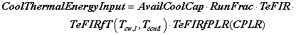
The CEIRfT curve represents the fraction of the electricity to the chiller at full load as it varies with temperature. The curve is normalized so that at design conditions the of the curve should be 1.0. The curve is usually a biquadratic or bilinear curve with the input variables being the leaving chilled water temperature and either the entering or leaving condenser water temperature (see Temperature Curve Input Variable below).
The CEIRfPLR curve represents the fraction of the electricity to the chiller as the load on the chiller varies but This operating temperatures remain at the design values. The curve is normalized so that at full load the value of the curve should be 1.0. The curve is usually linear or quadratic.
The cooling electric input to the chiller is computed as follows:
![]()
The HeatCapFCPLR curve represents how the heating capacity of the chiller varies with cooling capacity when the chiller is simultaneously heating and cooling. The curve is normalized so an input of 1.0 represents the nominal cooling capacity and an output of 1.0 represents the full heating capacity (see the Heating to Cooling Capacity Ratio input) The curve is usually linear or quadratic.
The available heating capacity is computed as follows:
![]()
When the chiller is operating as only a heater, the curve is used to represent the fraction of Thermal Energy used as the heating load varies. It is normalized so that a value of 1.0 is the full available heating capacity. The curve is usually linear or quadratic and will probably be similar to a boiler curve for most chillers.
The heating Thermal Energy Input to the chiller is computed as follows:
![]()
This field sets the second independent variable in the three temperature dependent performance curves to the entering condenser water temperature. Manufacturers express the performance of their chillers typically using the entering condenser water temperature (from the tower). ). This alpha field contains the keyword for the type of temperature input variable, , either EnteringCondenserTemperature, or LeavingCondenserTemperature. The default is EnteringCondenserTemperature.
The condenser can either be air cooled or water cooled (connected to a cooling tower). This alpha field contains the keyword for the type of condenser, either AirCooled, or WaterCooled. The default is WaterCooled.
The chilled water supply temperature in degrees C below which the chiller will shut off. The default is 2°C.
This alpha field determines the type of exhaust source the chiller uses. The default is MicroTurbine. Key Generator:MicroTurbine
This alpha field shows the name of the Exhaust source object – a Generator:MicroTurbine in this case
This optional numeric field allows the user to specify a sizing factor for this component. Min value should not be less than 0 and here is no max. The default is 1. The sizing factor is used when the component design inputs are autosized: the autosizing calculations are performed as usual and the results are multiplied by the sizing factor. For this component the inputs that would be altered by the sizing factor are: Nominal Cooling Capacity, Design Chilled Water Flow Rate, Design Condenser Water Flow Rate and Design Hot Water Flow Rate. Sizing Factor allows the user to size a component to meet part of the design load while continuing to use the autosizing feature.
An example of this statement in an IDF is:
ChillerHeater:Absorption:DoubleEffect,,
Exh Chiller, !- Chiller Name
100000, !- Nominal Cooling Capacity {W}
0.8, !- Heating to Cooling capacity ratio
0.97, !- Thermal Energy Input to Cooling Output Ratio
1.25, !- Thermal Energy Input to Heating Output Ratio
0.01, !- Electric Input to Cooling Output Ratio
0.005, !- Electric Input to Heating Output Ratio
Exh Chiller Inlet Node, !- Chilled Water Side Inlet Node Name
Exh Chiller Outlet Node, !- Chilled Water Side Outlet Node Name
Exh Chiller Condenser Inlet Node, !- Condenser Side Inlet Node Name
Exh Chiller Condenser Outlet Node, !- Condenser Side Outlet Node Name
Exh Chiller Heating Inlet Node, !- Hot Water Side Inlet Node Name
Exh Chiller Heating Outlet Node, !- Hot Water Side Outlet Node Name
0.000001, !- Minimum Part Load Ratio
1.0, !- Maximum Part Load Ratio
0.6, !- Optimum Part Load Ratio
29, !- Design Entering Condenser Water Temperature {C}
7, !- Design Leaving Chilled Water Temperature {C}
0.0011, !- Design Chilled Water Flow Rate {m3/s}
0.0011, !- Design Condenser Water Flow Rate {m3/s}
0.0043, !- Design Hot Water Flow Rate {m3/s}
ExhAbsorb_CapFt, !- Cooling Capacity Function of Temperature Curve Name
ExhAbsorb_EIRFt, !- Thermal Energy Input to Cooling Output Ratio Function of Temperature Curve Name
ExhAbsorb_PLR, !- Thermal Energy Input to Cooling Output Ratio Function of Part Load Ratio Curve Name
ExhAbsFlatBiQuad, !- Electric Input to Cooling Output Ratio Function of Temperature Curve Name
ExhAbsFlatQuad, !- Electric Input to Cooling Output Ratio Function of Part Load Ratio Curve Name
ExhAbsInvLinearQuad, !- Heating Capacity Function of Cooling Capacity Curve Name
ExhAbsLinearQuad, !- Thermal Energy Input to Heat Output Ratio During Heating Only Operation Curve Name
EnteringCondenser, !- Temperature Curve Input Variable
WaterCooled, !- Condenser Type
2, !- Chilled Water Temperature Lower Limit {C}
Generator:MicroTurbine ; ! Field Exhaust Source Object Type
Capston500 ; ! Field Exhaust Source name
1.0; !- Sizing Factor
HVAC,Average,Chiller Electric Power [W]
HVAC,Sum,Chiller Electric Consumption [J]
Zone,Meter,Electricity:Plant [J]
Zone,Meter,Cooling:Electricity [J]
HVAC,Average,Chiller Evap Heat Trans Rate [W]
HVAC,Sum,Chiller Evap Heat Trans [J]
Zone,Meter,EnergyTransfer:Plant [J]
Zone,Meter,Chillers:EnergyTransfer [J]
HVAC,Average,Chiller Evap Water Inlet Temp [C]
HVAC,Average,Chiller Evap Water Outlet Temp [C]
HVAC,Average,Chiller Evap Water Mass Flow Rate [kg/s]
HVAC,Average,Chiller Cond Heat Trans Rate [W]
HVAC,Sum,Chiller Cond Heat Trans [J]
Zone,Meter,HeatRejection:EnergyTransfer [J]
The following output is applicable only for air-cooled chillers
HVAC,Average,Chiller Cond Air Inlet Temp [C]
The following three outputs are only available for water-cooled chillers
HVAC,Average,Chiller Cond Water Inlet Temp [C]
HVAC,Average,Chiller Cond Water Outlet Temp [C]
HVAC,Average,Chiller Cond Water Mass Flow Rate [kg/s]
Outputs specific to Exhaust Fired Absorption Chiller
HVAC,Average,Exhaust Fired Absorption Chiller Fraction of Period Running
Outputs specific to Exhaust Fired Absorption Chiller during cooling operation
HVAC,Average,Exhaust Fired Absorption Chiller Cooling Electric Power [W]
HVAC,Sum,Exhaust Fired Absorption Chiller Cooling Electric Consumption [J]
HVAC,Average,Exhaust Fired Absorption Chiller Cooling Part Load Ratio
HVAC,Average,Exhaust Fired Absorption Chiller Cooling Capacity [W]
HVAC,Average,Exhaust Fired Absorption Chiller Cooling Thermal Energy COP [W/W]
Outputs specific to Exhaust Fired Absorption Chiller during heating operation
HVAC,Average,Exhaust Fired Absorption Chiller Heating Rate [W]
HVAC,Sum,Exhaust Fired Absorption Chiller Heating Energy [J]
Zone,Meter,Boilers:EnergyTransfer [J]
HVAC,Average,Exhaust Fired Absorption Chiller Heating Electric Power [W]
HVAC,Sum,Exhaust Fired Absorption Chiller Heating Electric Consumption [J]
Zone,Meter,Heating:Electricity [J]
HVAC,Average,Exhaust Fired Absorption Chiller Heating Part Load Ratio
HVAC,Average,Exhaust Fired Absorption Chiller Heating Capacity [W]
HVAC,Average,Exhaust Fired Absorption Chiller Hot Water Inlet Temp [C]
HVAC,Average,Exhaust Fired Absorption Chiller Hot Water Outlet Temp [C]
HVAC,Average,Exhaust Fired Absorption Chiller Hot Water Mass Flow Rate [kg/s]
The "Chiller" output variables are defined above under "Generic Chiller Outputs." The specific "Exhaust Fired Absorption Chiller" output variables and exceptions to the generic outputs are defined below.
These outputs are the electric power input to the chiller when operating in cooling mode, heating mode, or both. This value is not metered, but the separate cooling and heating electric consumption are metered (see below).
This is the average fraction of the time period during which the Exhaust Fired absorption chiller-heater was operating in either cooling mode, heating mode, or both.
These outputs are the electricity input to the Exhaust Fired absorption chiller to serve cooling operation. Consumption is metered on Cooling:Electricity, Electricity:Plant, and Electricity:Facility.
This is the average available cooling capacity for the reported time period.
This is the average cooling load (Chiller Evap Heat Trans Rate [W]) divided by the average available cooling capacity (Exhaust Fired Absorption Chiller Cooling Capacity [W]) for the reported time period.
This is the average coefficient of performance for the chiller in cooling operation, calculated as the average cooling load (Chiller Evap Heat Trans Rate [W]) divided by the average thermal energy use during cooling (Exhaust Fired Absorption Chiller Cooling Thermal Energy use Rate [W]) for the reported time period. If the chiller cooling thermal energy use rate (denominator) is zero, then this output variable is set to zero.
These outputs are the electric power input to the Exhaust Fired absorption chiller to serve heating operation. Consumption is metered on Heating:Electricity, Electricity:Plant, and Electricity:Facility.
This is the average available heating capacity for the reported time period.
This is the average heating load (Exhaust Fired Absorption Chiller Heating Rate [W]) divided by the average available heating capacity (Exhaust Fired Absorption Chiller Heating Capacity [W]) for the reported time period.
These outputs are the hot water inlet and outlet temperatures and flow rate for the Exhaust Fired absorption chiller-heater during heating mode operation.
Exhaust Fired Absorption Chiller Heat Recovery Potential-During Heating (W)
The heat recovery potential calculated based on Microturbine exhaust temperature and flow rate during heating mode
Exhaust Fired Absorption Chiller Thermal Energy Consumption Rate-During Heating (W)
The thermal energy consumption rate required for heating.
Exhaust Fired Absorption Chiller Heat Recovery Potential-During Cooling (W)
The heat recovery potential calculated based on Microturbine exhaust temperature and flow rate during cooling mode.
Exhaust Fired Absorption Chiller Thermal Energy Consumption Rate-During Cooling (W)
The thermal energy consumption rate required for cooling.
The boiler model calculates the performance of fuel oil, gas and electric boilers. Boiler performance is based on nominal thermal efficiency. A normailized efficiency performance curve may be used to more accurately represent the performance of non-electric boilers but is not considered a required input. When using the normalized efficiency performance curve, if all coefficients are not required simply set the unused coefficients to 0. For example, an electric boiler could be modeled by setting the nominal thermal efficiency to a value in the range of 0.96 to 1.0. Coefficient A0 in the normalized efficiency performance curve would equal 1 and all other coefficients would be set to 0. Coefficients for other types of non-electric boilers would set a combination of the available coefficents to non-zero values.
This required alpha field contains the identifying name for the boiler.
This required choice field specifies the type of fuel used by the boiler. The fuel type can be Electricity, NaturalGas, PropaneGas, FuelOil#1, FuelOil#2, Coal, Diesel, or Gasoline.
This numeric field contains the nominal operating capacity (W) of the boiler. The boiler may be autosized and would require a heating plant sizing object.
The model is based the following two equations:
![]()
![]()
This required numeric field contains the heating efficiency (as a fraction between 0 and 1) of the boiler’s burner. This is the efficiency relative to the higher heating value (HHV) of fuel at a part load ratio of 1.0 and the temperature entered for the Design Boiler Water Outlet Temp. Manufacturers typically specify the efficiency of a boiler using the higher heating value of the fuel. For the rare occurences when a manufacturers (or particular data set) thermal efficiency is based on the lower heating value (LHV) of the fuel, multiply the thermal efficiency by the lower-to-higher heating value ratio. For example, assume a fuel’s lower and higher heating values are approximately 45,450 and 50,000 kJ/kg, respectively. For a manuracturers thermal effiency rating of 0.90 (based on the LHV), the nominal thermal efficiency entered here is 0.82 (i.e. 0.9 multiplied by 45,450/50,000).
This field is used to control which value for hot water temperature is used when evaluating the efficiency curve specified in the next field (if applicable). There are two options, EnteringBoiler or LeavingBoiler. EnteringBoiler indicates that the efficiency curves will be evaluated using the temperature at boiler inlet node. LeavingBoiler indicates that the efficiency curves will be evaluated using the temperature at the boiler outlet. This field is only used if type of curve is one that uses temperature as a independent variable.
This alpha field contains the curve name which describes the normalized heating efficiency (as a fraction of nominal thermal efficiency) of the boiler’s burner. If this field is left blank, the nominal thermal efficiency is assumed to be constant (i.e., Fuel Used is equal to the Theoretical Fuel Use in the equation above). When a boiler efficiency curve is used, the curve may be any valid curve object with 1 (PLR) or 2 (PLR and boiler outlet water temperature) independent variables. A tri-quadratic curve object is not allowed since it uses 3 independent variables. The linear, quadratic, and cubic curve types may be used when the boiler efficiency is soley a function of boiler part-load ratio (PLR). When this type of curve is used, the boiler should operate at (or very near) the design boiler water outlet temperature. Other curve types may be used when the boiler efficiency is a function of both PLR and boiler water temperature. Examples of valid single and dual independent variable equations are shown below. For all curve types PLR is always the x independent variable. When using 2 independent variables, the boiler outlet water temperature (Toutlet) is always the y independent variable.
Linear: Eff = A0 + A1*PLR
Quadratic: Eff = A0 + A1*PLR + A2*PLR2
Cubic: Eff = A0 + A1*PLR + A2*PLR2 + A3*PLR3
BiQuadratic: Eff = A0 + A1*PLR + A2*PLR2 + A3* Tw + A4* Tw 2 + A5*PLR* Tw
QuadraticLinear: Eff = A0 + A1*PLR + A2*PLR2 + A3* Tw + A4*PLR* Tw + A5*PLR2* Tw
BiCubic: Eff=A0+A1*PLR+A2*PLR2+A3*Tw+A4*Tw2+A5*PLR2+A6*Tw3+A7*PLR2* Tw+A8*PLR* Tw2
where
Eff = normalized boiler efficiency
PLR = boiler part-load ratio
Tw = boiler water temperature [ºC] ], this can be either entering or leaving temperature depending on the setting in the previous field
This numeric field contains the desired boiler water outlet temperature in Celsius.
This numeric field contains the maximum design water volumetric flow rate in m3/sec. This should be the largest flow rate than can be heated to the design outlet temperature. This field is autosizable.
This numeric field contains the minimum part load ratio. If the ratio of demand to boiler nominal capacity is less than the minimum part load ratio, then the Min PLR will determine the operating PLR. The expected range is between 0 and 1. If this field is left blank, the default value is 0.0.
This numeric field contains the maximum part load ratio. If the ratio of demand to boiler nominal capacity is greater than the maximum part load ratio, then the Max PLR will determine the operating PLR. This value may exceed 1, but the normal range is between 0 and 1.1. If this field is left blank, the default value is 1.0.
This numeric field contains the optimum part load ratio. This is the part load ratio at which the boiler performs at its maximum efficiency. If this field is left blank, the default value is 1.0.
This required alpha field contains the water inlet node name.
This required alpha field contains the water outlet node name.
This numeric field contains the outlet temperature upper limit. If this field is left blank, the default value is 99.9ºC.
This choice field determines if the boiler is VariableFlow or ConstantFlow. The default, if not specified, is VariableFlow.
This optional numeric field contains the parasitic electric power (W) consumed by a forced draft fan or other electrical device associated with the boiler. This parasitic electric load is consumed whenever the boiler is operating, and the model assumes that this parasitic power does not contribute to heating the water. The minimum value for this field is 0.0, and the default value is also 0.0 if the field is left blank.
This optional numeric field allows the user to specify a sizing factor for this component. The sizing factor is used when the component design inputs are autosized: the autosizing calculations are performed as usual and the results are multiplied by the sizing factor. For this component the inputs that would be altered by the sizing factor are: Nominal Capacity and Design Water Flow Rate. Sizing factor allows the user to size a component to meet part of the design load while continuing to use the autosizing feature.
An example of this statement in an IDF is:
Boiler:HotWater,
Condensing Boiler, !- Boiler Name
GAS, !- Fuel Type
25000, !- Nominal Capacity {W}
EnteringBoiler !- Efficiency Curve Temperature Evaluation Variable
0.89, !- Nominal Thermal Efficiency
CondensingBoilerEff, !- Boiler Efficiency Curve Name
75, !- Design Boiler Water Outlet Temp {C}
0.0021, !- Max Design Boiler Water Flow Rate {m3/s}
0.10, !- Minimum Part Load Ratio
1.00, !- Maximum Part Load Ratio
1.00, !- Optimum Part Load Ratio
Boiler Inlet Node, !- Boiler Water Inlet Node
Boiler Outlet Node, !- Boiler Water Outlet Node
80, !- Temp Upper Limit Water Outlet {C}
ConstantFlow, !- Boiler Flow Mode
25.0; !- Parasitic Electric Load {W}
Curve:Biquadratic,
CondensingBoilerEff, !- Name
1.124970374, !- Coefficient1 Constant
0.014963852, !- Coefficient2 x
-0.02599835, !- Coefficient3 x**2
0.0, !- Coefficient4 y
-1.40464E-6, !- Coefficient5 y**2
-0.00153624, !- Coefficient6 x*y
0.1, !- Minimum Value of x
1.0, !- Maximum Value of x
30.0, !- Minimum Value of y
85.0; !- Maximum Value of y
Outputs available from the boiler:
HVAC,Average,Boiler Heating Output Rate [W]
HVAC,Sum,Boiler Heating Output Energy [J]
Zone,Meter,Boilers:EnergyTransfer [J]
HVAC,Average,Boiler Water Inlet Temp [C]
HVAC,Average,Boiler Water Outlet Temp [C]
HVAC,Average,Boiler Water Mass Flow Rate [kg/s]
HVAC,Average,Boiler Parasitic Electric Power [W]
HVAC,Sum,Boiler Parasitic Electric Consumption [J]
HVAC,Average,Boiler Part-Load Ratio
One of the following blocks will be applicable based on fuel type:
HVAC,Average,Boiler Electric Consumption Rate [W]
HVAC,Sum,Boiler Electric Consumption [J]
Zone,Meter, Electricity:Plant [J]
Zone,Meter,Heating:Electricity [J]
HVAC,Average,Boiler Gas Consumption Rate [W]
HVAC,Sum,Boiler Gas Consumption [J]
Zone,Meter,Gas:Plant [J]
Zone,Meter,Heating:Gas [J]
HVAC,Average,Boiler Propane Consumption Rate [W]
HVAC,Sum,Boiler Propane Consumption [J]
Zone,Meter, Propane:Plant [J]
Zone,Meter,Heating:Propane [J]
HVAC,Average,Boiler FuelOil#1 Consumption Rate [W]
HVAC,Sum,Boiler FuelOil#1 Consumption [J]
Zone,Meter, FuelOil#1:Plant [J]
Zone,Meter,Heating:FuelOil#1 [J]
HVAC,Average,Boiler FuelOil#2 Consumption Rate [W]
HVAC,Sum,Boiler FuelOil#2 Consumption [J]
Zone,Meter, FuelOil#2:Plant [J]
Zone,Meter,Heating:FuelOil#2 [J]
HVAC,Average,Boiler Coal Consumption Rate [W]
HVAC,Sum,Boiler Coal Consumption [J]
Zone,Meter,Coal:Plant [J]
Zone,Meter,Heating:Coal [J]
HVAC,Average,Boiler Diesel Consumption Rate [W]
HVAC,Sum,Boiler Diesel Consumption [J]
Zone,Meter, Diesel:Plant [J]
Zone,Meter,Heating:Diesel [J]
HVAC,Average,Boiler Gasoline Consumption Rate [W]
HVAC,Sum,Boiler Gasoline Consumption [J]
Zone,Meter, Gasoline:Plant [J]
Zone,Meter,Heating:Gasoline [J]
These outputs are the heating output (load) of the boiler. Energy is metered on Boilers:EnergyTransfer, EnergyTransfer:Plant, and EnergyTransfer:Facility.
These outputs are the hot water inlet and outlet temperatures and flow rate for the boiler.
This output is the operating part-load ratio of the boiler. The part-load ratio is calculated as the boiler load divided by the boiler nominal capacity. The part-load ratio is limited by the minimum and maximum part-load ratio inputs specified by the user.
These outputs are the energy input to the boiler. Valid fuel types are: Electric, Gas (natural gas), Propane, FuelOil#1, FuelOil#2, Coal, Diesel, and Gasoline. Consumption is metered on Heating:<FuelType>, <FuelType>:Plant, and <FuelType>:Facility.
These outputs are the parasitic electric power and parasitic electric consumption associated with the boiler. Used when simulating a forced draft fan or other electric component. Consumption is metered on Heating:Electricity and Electricity:Plant.
The steam boiler model provides a first order approximation of performance for fuel oil, gas and electric boilers. Boiler performance is based on a “theoretical” boiler efficiency (overall efficiency at design operating conditions) and a single quadratic fuel use/ part load ratio curve. This single curve accounts for all combustion inefficiencies and stack losses.
This alpha field contains the identifying name for the Steam Boiler.
This alpha value specifies the type of fuel used by the boiler. The fuel type can be Electricity, NaturalGas, PropaneGas, FuelOil#1, FuelOil#2, Coal, Diesel, or Gasoline.
This numeric field contains the maximum value of pressure up to which the boiler would operate, or the maximum design pressure. (Pascal)
This numeric field contains the heating efficiency (as a fraction between 0 and 1) of the boiler’s burner
The maximum value of steam temperature the boiler can provide. (Celcius)
This numeric field contains the nominal operating capacity (W) of the boiler.
This numeric field contains the minimum part load ratio. If the ratio of demand to boiler nominal capacity is less than the minimum part load ratio, then the Min PLR will determine the operating PLR. The expected range is between 0 and 1.
This numeric field contains the maximum part load ratio. If the ratio of demand to boiler nominal capacity is greater than the maximum part load ratio, then the Max PLR will determine the operating PLR. This value may exceed 1, but the normal range is between 0 and 1.1.
This numeric field contains the optimum part load ratio. This is the part load ratio at which the boiler performs at its maximum efficiency.
This numeric field contains the fuel use / PLR coefficient1.
This numeric field contains the fuel use / PLR coefficient2.
This numeric field contains the fuel use / PLR coefficient3.
This alpha field contains the water inlet node name.
This alpha field contains the steam outlet node name.
This optional numeric field allows the user to specify a sizing factor for this component. The sizing factor is used when the component design inputs are autosized: the autosizing calculations are performed as usual and the results are multiplied by the sizing factor. For this component the inputs that would be altered by the sizing factor are: Nominal Capacity. Sizing factor allows the user to size a component to meet part of the design load while continuing to use the autosizing feature.
More information on the technical aspects of steam boiler can be found in the Engineering Reference Document.
An example of a Steam Boiler input statement from an IDF is:
Boiler:Steam,
Steam Boiler Plant Boiler, !- Boiler Name
NaturalGas, !- Fuel Type
160000, !-Maximum Boiler Pressure Pascal
0.8, !- Theoretical Boiler Efficiency
115, !- Max Design Outlet Steam Temp
300000, !- Nominal Capacity W
0.00001, !- Minimum Part Load Ratio
1.0, !- Maximum Part Load Ratio
0.2, !- Optimum Part Load Ratio
0.8,!- Coefficient 1 of the fuel use/part load ratio curve
0.1,!- Coefficient 2 of the fuel use/part load ratio curve
0.1,!- Coefficient 3 of the fuel use/part load ratio curve
Steam Boiler Plant Boiler Inlet Node, !- Boiler Steam Inlet Node
Steam Boiler Plant Boiler Outlet Node; !- Plant Loop Outlet Node
Boiler:Steam,
Steam Boiler Plant Boiler, !- Boiler Name
NaturalGas, !- Fuel Type
160000, !-Maximum Boiler Pressure Pascal
0.8, !- Theoretical Boiler Efficiency
115, !- Max Design Outlet Steam Temp
autosize, !- Nominal Capacity W
0.00001, !- Minimum Part Load Ratio
1.0, !- Maximum Part Load Ratio
0.2, !- Optimum Part Load Ratio
0.8,!- Coefficient 1 of the fuel use/part load ratio curve
0.1,!- Coefficient 2 of the fuel use/part load ratio curve
0.1,!- Coefficient 3 of the fuel use/part load ratio curve
Steam Boiler Plant Boiler Inlet Node, !- Boiler Steam Inlet Node
Steam Boiler Plant Boiler Outlet Node; !- Plant Loop Outlet Node
Outputs available from the steam boiler:
HVAC,Average,Boiler Heating Output Rate [W]
HVAC,Sum,Boiler Heating Output Energy [J]
Zone,Meter,Boilers:EnergyTransfer [J]
HVAC,Average,Boiler Water Inlet Temp [C]
HVAC,Average,Boiler Steam Outlet Temp [C]
HVAC,Average,Boiler Water Mass Flow Rate [kg/s]
One of the following blocks will be applicable based on fuel type:
HVAC,Average,Boiler Electric Consumption Rate [W]
HVAC,Sum,Boiler Electric Consumption [J]
Zone,Meter, Electricity:Plant [J]
Zone,Meter,Heating:Electricity [J]
HVAC,Average,Boiler Gas Consumption Rate [W]
HVAC,Sum,Boiler Gas Consumption [J]
Zone,Meter,Gas:Plant [J]
Zone,Meter,Heating:Gas [J]
HVAC,Average,Boiler Propane Consumption Rate [W]
HVAC,Sum,Boiler Propane Consumption [J]
Zone,Meter, Propane:Plant [J]
Zone,Meter,Heating:Propane [J]
HVAC,Average,Boiler FuelOil#1 Consumption Rate [W]
HVAC,Sum,Boiler FuelOil#1 Consumption [J]
Zone,Meter, FuelOil#1:Plant [J]
Zone,Meter,Heating:FuelOil#1 [J]
HVAC,Average,Boiler FuelOil#2 Consumption Rate [W]
HVAC,Sum,Boiler FuelOil#2 Consumption [J]
Zone,Meter, FuelOil#2:Plant [J]
Zone,Meter,Heating:FuelOil#2 [J]
HVAC,Average,Boiler Coal Consumption Rate [W]
HVAC,Sum,Boiler Coal Consumption [J]
Zone,Meter,Coal:Plant [J]
Zone,Meter,Heating:Coal [J]
HVAC,Average,Boiler Diesel Consumption Rate [W]
HVAC,Sum,Boiler Diesel Consumption [J]
Zone,Meter, Diesel:Plant [J]
Zone,Meter,Heating:Diesel [J]
HVAC,Average,Boiler Gasoline Consumption Rate [W]
HVAC,Sum,Boiler Gasoline Consumption [J]
Zone,Meter, Gasoline:Plant [J]
Zone,Meter,Heating:Gasoline [J]
These outputs are the heating output (load) of the boiler. Energy is metered on Boilers:EnergyTransfer, EnergyTransfer:Plant, and EnergyTransfer:Facility.
These outputs are the hot water inlet and Steam outlet temperatures and steam flow rate for the boiler.
These outputs are the energy input to the boiler. Valid fuel types are: Electric, Gas (natural gas), Propane, FuelOil#1, FuelOil#2, Coal, Diesel, and Gasoline. Consumption is metered on Heating:<FuelType>, <FuelType>:Plant, and <FuelType>:Facility.
The EnergyPlus has two water-to-water heat pump models, parameter estimation and equation fit, to choose from:
HeatPump:WaterToWater:EquationFit:Cooling
HeatPump:WaterToWater:EquationFit:Heating
This model is an equation-fit model from the catalog data which resembles a black box with no usage of heat transfer equations. The performance of the heat pump is modeled using curves fitted from the catalog data.
HeatPump:WaterToWater:ParameterEstimation:Cooling
HeatPump:WaterToWater:ParameterEstimation:Heating
This model is a parameter estimation based model that uses physical parameters generated from the catalog data. The physical parameters are then used to predict the performance of the heat pump using thermodynamic laws and heat transfer equations. The heat pump has a reciprocating compressor that serves both the hot water and the chilled water loop. Note that this model is currently “hardwired” to fluid property R22.
Descriptions and strength of each respective model is available in the following references:
Jin, Hui. 2002. Parameter Estimation Based Models of Water Source Heat Pumps. Phd. Thesis, Department of Mechanical and Aerospace Engineering, Oklahoma State University. (downloadable from http://www.hvac.okstate.edu/)
Tang,C. C. 2005. Modeling Packaged Heat Pumps in Quasi-Steady State Energy Simulation Program. M.S. Thesis. Department of Mechanical and Aerospace Engineering, Oklahoma State University. (downloadable from http://www.hvac.okstate.edu/)
The Supply side of the heat pump is usually connected to a Ground Heat Exchanger. The figure below shows the layout and piping diagram of the water-to-water heat pump.
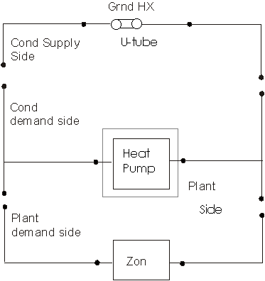
Figure 64. Schematic of EnergyPlus Ground Loop Heat Exchanger
First, the equation fit model objects are described. This model has two sets of coefficients, one for the heating mode and other for the cooling mode.
This alpha field contains the identifying name for the ground source heat pump.
This alpha field contains the heat pump’s source side inlet node name.
This alpha field contains the heat pump’s source side outlet node name.
This alpha field contains the heat pump’s load side inlet node name.
This alpha field contains the heat pump’s load side outlet node name.
This numeric field contains the rated volumetric flow rate on the load side of the heat pump in m3/s.
This numeric field contains the rated volumetric flow rate on the source side of the heat pump in m3/s.
This numeric field contains the rated cooling capacity of the heat pump in W.
This numeric field contains the rated power consumption of the heat pump in W.
Five fields are used to describe the coefficients for the Cooling Capacity curve. More details on how these coefficients are used are described in the Engineering Reference.
These numeric fields contain the five coefficients for the heat pump capacity.
Five fields are used to describe the coefficients for the Cooling Compressor Power consumption curve. More details on how these coefficients are used are described in the Engineering Reference.
These numeric fields contain the five coefficients for the heat pump power consumption.
This numeric field contains the full on and off cycle time of the heat pump unit in Hour.
An idf example:
HeatPump:WaterToWater:EquationFit:Cooling,
GshpCLG, !- Water to Water Heat Pump Name
GshpCLG SourceSide Inlet Node, !- Source Side Inlet Node
GshpCLG SourceSide Outlet Node, !- Source Side Outlet Node
GshpCLG LoadSide Inlet Node, !- Load Side Inlet Node
GshpCLG LoadSide Outlet Node, !- Load Side Outlet Node
1.89E-03, !- Rated Load Side Flow Rate {m3/s}
1.89E-03, !- Rated Source Side Flow Rate {m3/s}
39890.91, !- Rated Cooling Capacity {W}
4790.00, !- Rated Cooling Power Consumption {W}
-1.52030596, !- Cooling Capacity Coefficient 1
3.46625667, !- Cooling Capacity Coefficient 2
-1.32267797, !- Cooling Capacity Coefficient 3
0.09395678, !- Cooling Capacity Coefficient 4
0.038975504, !- Cooling Capacity Coefficient 5
-8.59564386, !- Cooling Compressor Power Coefficient 1
0.96265085, !- Cooling Compressor Power Coefficient 2
8.69489229, !- Cooling Compressor Power Coefficient 3
0.02501669, !- Cooling Compressor Power Coefficient 4
-0.20132665, !- Cooling Compressor Power Coefficient 5
0.1; !- Heat pump unit's cycle time {hr}
This alpha field contains the identifying name for the ground source heat pump.
This alpha field contains the heat pump’s source side inlet node name.
This alpha field contains the heat pump’s source side outlet node name.
This alpha field contains the heat pump’s load side inlet node name.
This alpha field contains the heat pump’s load side outlet node name.
This numeric field contains the rated volumetric flow rate on the load side of the heat pump in m3/s.
This numeric field contains the rated volumetric flow rate on the source side of the heat pump in m3/s.
This numeric field contains the rated heating capacity of the heat pump in W.
This numeric field contains the rated power consumption of the heat pump in W.
Five fields are used to describe the coefficients for the Heating Capacity curve. More details on how these coefficients are used are described in the Engineering Reference.
These numeric fields contain the five coefficients for the heat pump capacity.
Five fields are used to describe the coefficients for the Heating Compressor Power consumption curve. More details on how these coefficients are used are described in the Engineering Reference.
These numeric fields contain the five coefficients for the heat pump power consumption.
This numeric field contains the full on and off cycle time of the heat pump unit in Hour.
An idf example:
HeatPump:WaterToWater:EquationFit:Heating,
GshpHeating, !- Water to Water Heat Pump Name
GshpHeating SourceSide Inlet Node, !- Source Side Inlet Node
GshpHeating SourceSide Outlet Node, !- Source Side Outlet Node
GshpHeating LoadSide Inlet Node, !- Load Side Inlet Node
GshpHeating LoadSide Outlet Node, !- Load Side Outlet Node
1.89E-03, !- Rated Load Side Flow Rate {m3/s}
1.89E-03, !- Rated Source Side Flow Rate {m3/s}
39040.92, !- Rated Heating Capacity {W}
5130.00, !- Rated Heating Power Consumption {W}
-3.33491153, !- Heating Capacity Coefficient 1
-0.51451946, !- Heating Capacity Coefficient 2
4.51592706, !- Heating Capacity Coefficient 3
0.01797107, !- Heating Capacity Coefficient 4
0.155797661, !- Heating Capacity Coefficient 5
-8.93121751, !- Heating Compressor Power Coefficient 1
8.57035762, !- Heating Compressor Power Coefficient 2
1.29660976, !- Heating Compressor Power Coefficient 3
-0.21629222, !- Heating Compressor Power Coefficient 4
0.033862378, !- Heating Compressor Power Coefficient 5
0.15; !- Heat pump unit's cycle time {hr}
Next, the parameter estimation model objects are described. This model has two sets of parameters, one for the heating mode and other for the cooling mode.
This alpha field contains the identifying name for the ground source heat pump.
This alpha field contains the heat pump’s source side inlet node name.
This alpha field contains the heat pump’s source side outlet node name.
This alpha field contains the heat pump’s load side inlet node name.
This alpha field contains the heat pump’s load side outlet node name.
This numeric field contains the nominal coefficient of performance of the heat pump.
This numeric field contains the nominal capacity of the heat pump in Watts.
This numeric field contains the minimum part load ratio of the heat pump usually set to 0.
This numeric field contains the maximum part load ratio of the heat pump usually set to 1.
This numeric field contains the optimal part load ratio of the heat pump usually set to 1.
This numeric field contains the volumetric flow rate on the load side of the heat pump in m3/s
This numeric field contains the volumetric flow rate on the source side of the heat pump in m3/s
This numeric field contains Estimated parameter load side heat transfer coefficient W/K.
This numeric field contains Estimated parameter source side heat transfer coefficient W/K.
This numeric field contains the Estimated parameter displacement of the reciprocating compressor in m3/s.
This numeric field contains the Estimated parameter clearance factor of the reciprocating compressor.
This numeric field contains the estimated parameter the pressure drop at compressor suction and discharge in Pascals (N/m2).
This numeric field contains the estimated parameter superheat at the evaporator outlet in °C.
This numeric field contains the estimated parameter power loss, which accounts for the loss of work due mechanical and electrical losses in the compressor in Watts.
This numeric field contains the factor of electromechanical loss that is proportional to the theoretical power percentage.
This numeric field contains the design pressure limit of the compressor in Pascals (N/m2).
This numeric field contains the design low-pressure limit of the compressor in Pascals (N/m2).
This numeric field contains the full on and off cycle time of the heat pump unit in Hour.
An idf example:
HeatPump:WaterToWater:ParameterEstimation:Cooling,
GshpCLG, !- Water to Water Heat Pump Name
GshpCLG SourceSide Inlet Node, !- Source Side Inlet Node
GshpCLG SourceSide Outlet Node, !- Source Side Outlet Node
GshpCLG LoadSide Inlet Node, !- Load Side Inlet Node
GshpCLG LoadSide Outlet Node, !- Load Side Outlet Node
3.5, !- Nominal COP
45000, !- Nominal Capacity {W}
0.0, !- Min PLR
1, !- Max PLR
1, !- optimum PLR
.003, !- Load side Flow Rate {m3/s}
.003, !- Source Side Flow Rate {m3/s}
7761, !- Load side Heat Transfer Coefficient {W/K}
3998, !- Source Side Heat Transfer Coefficient {W/K}
.012544, !- Piston Displacement {m3/s}
.05469, !- Compressor Clearance Factor %
92156.2, !- Compressor Suction And Discharge Pressure Drop {Pa}
4.8907, !- Superheating {C}
2803.9, !- Constant Part of Electro Mechanical Power Losses {W}
.699, !- Loss Factor
0.0, !- High Pressure Cut off {Pa}
0.0, !- LowPressure Cut off {Pa}
0.1; !- Heat pump unit's cycle time {hr}
This alpha field contains the identifying name for the ground source heat pump.
This alpha field contains the heat pump’s source side inlet node name.
This alpha field contains the heat pump’s source side outlet node name.
This alpha field contains the heat pump’s load side inlet node name.
This alpha field contains the heat pump’s load side outlet node name.
This numeric field contains the nominal coefficient of performance of the heat pump.
This numeric field contains the nominal capacity of the heat pump in Watts.
This numeric field contains the minimum part load ratio of the heat pump usually set to 0.
This numeric field contains the maximum part load ratio of the heat pump usually set to 1.
This numeric field contains the optimal part load ratio of the heat pump usually set to 1.
This numeric field contains the volumetric flow rate on the load side of the heat pump in m3/s
This numeric field contains the volumetric flow rate on the source side of the heat pump in m3/s
This numeric field contains Estimated parameter load side heat transfer coefficient W/K.
This numeric field contains Estimated parameter source side heat transfer coefficient W/K.
This numeric field contains the Estimated parameter displacement of the reciprocating compressor in m3/s.
This numeric field contains the Estimated parameter clearance factor of the reciprocating compressor.
This numeric field contains the estimated parameter the pressure drop at compressor suction and discharge in Pascals (N/m2).
This numeric field contains the estimated parameter superheat at the evaporator outlet in °C.
This numeric field contains the estimated parameter power loss, which accounts for the loss of work due mechanical and electrical losses in the compressor in Watts.
This numeric field contains the factor of electromechanical loss that is proportional to the theoretical power percentage.
This numeric field contains the design pressure limit of the compressor in Pascals (N/m2).
This numeric field contains the design low-pressure limit of the compressor in Pascals (N/m2).
This numeric field contains the full on and off cycle time of the heat pump unit in Hour.
An idf example:
HeatPump:WaterToWater:ParameterEstimation:Heating,
GshpHeating, !- Water to Water Heat Pump Name
GshpHeating SourceSide Inlet Node, !- Source Side Inlet Node
GshpHeating SourceSide Outlet Node, !- Source Side Outlet Node
GshpHeating LoadSide Inlet Node, !- Load Side Inlet Node
GshpHeating LoadSide Outlet Node, !- Load Side Outlet Node
3.5, !- Nominal COP
50000, !- Nominal Capacity {W}
0.0, !- Min PLR
1, !- Max PLR
1, !- optimum PLR
.003, !- Load side Flow Rate {m3/s}
.003, !- Source Side Flow Rate {m3/s}
7761, !- Load side Heat Transfer Coefficient {W/K}
3998, !- Source Side Heat Transfer Coefficient {W/K}
.012544, !- Piston Displacement {m3/s}
.05469, !- Compressor Clearance Factor %
92156.2, !- Compressor Suction And Dischrage Pressure Drop {Pa}
4.8907, !- Superheating {C}
2803.9, !- Constant Part Of Electro Mechanical Power Losses {W}
.699, !- Loss Factor
0.0, !- High Pressure Cut off {Pa}
0.0, !- LowPressure Cut off {Pa}
0.15; !- Heat pump unit's cycle time {hr}
Since the heat pump is defined with two separate objects (one for heating, one for cooling), the connections to the condenser has to be done carefully. The example below shows the configuration for parameter estimation objects. The same specifications and configuration also applies to the equation fit model.
For the heating mode:
1) Specify a branch for the Heat pump in hot water loop .
2) Include the branch name in the splitter and mixer branches.
3) Add a branch in condenser loop and include its name in the respective splitter and mixer.
! in hot water loop
BRANCH, Heating GshpHeating Branch,
,
,
HeatPump:WatertoWater:ParameterEstimatinon:Heating,
GshpHeating,
GshpHeating LoadSide Inlet Node,
GshpHeating LoadSide Outlet Node,
ACTIVE;
!in condenser loop
BRANCH, GshpHeating SourceSide Branch,
,
,
HeatPump:WatertoWater:ParameterEstimatinon:Heating,
GshpHeating,
GshpHeating SourceSide Inlet Node,
GshpHeating SourceSide Outlet Node,
ACTIVE;
Example of Heat Pump Links
For the cooling mode:
1) Specify a branch for the Heat pump in chilled water loop .
2) Include the branch name in the splitter and mixer branches.
3) Add a branch in condenser loop and include its name in the respective splitter and mixer.
! in chilled water loop
BRANCH,GshpCLG1 Chiller Branch,
,
,
HeatPump:WatertoWater:ParameterEstimatinon:Cooling, GshpCLG1,
GshpCLG LoadSide Inlet Node1,
GshpCLG LoadSide Outlet Node1,
Active;
!in condenser loop
BRANCH, GshpCLG1 Condenser Branch,
,
,
HeatPump:WatertoWater:ParameterEstimatinon:Cooling, GshpCLG1,
GshpCLG SourceSide Inlet Node1,
GshpCLG SourceSide Outlet Node1,
ACTIVE;
This section describes the outputs available for the water to water heat pump, parameter estimation model; both cooling and heating.
HVAC,Average,GSHP COOLING Electric Power [W]
HVAC,Average,GSHP HEATING Electric Power [W]
HVAC,Sum,GSHP COOLING Electric Consumption [J]
HVAC,Sum,GSHP HEATING Electric Consumption [J]
HVAC,Average,GSHP COOLING Load Side Heat Transfer Rate [W]
HVAC,Average,GSHP HEATING Load Side Heat Transfer Rate [W]
HVAC,Sum,GSHP COOLING Load Side Heat Transferred [J]
HVAC,Sum,GSHP HEATING Load Side Heat Transferred [J]
HVAC,Average,GSHP COOLING Source Side Heat Transfer Rate [W]
HVAC,Average,GSHP HEATING Source Side Heat Transfer Rate [W]
HVAC,Sum,GSHP COOLING Source Side Heat Transferred [J]
HVAC,Sum,GSHP HEATING Source Side Heat Transferred [J]
HVAC,Average,GSHP COOLING Load Side Outlet Temperature [°C]
HVAC,Average,GSHP HEATING Load Side Outlet Temperature [°C]
HVAC,Average,GSHP COOLING Load Side Inlet Temperature [°C]
HVAC,Average,GSHP HEATING Load Side Inlet Temperature [°C]
HVAC,Average,GSHP COOLING Source Side Outlet Temperature [°C]
HVAC,Average,GSHP HEATING Source Side Outlet Temperature [°C]
HVAC,Average,GSHP COOLING Source Side Inlet Temperature [°C]
HVAC,Average,GSHP HEATING Source Side Inlet Temperature [°C]
HVAC,Average,GSHP COOLING Load Side Water Mass Flow Rate[kg/s]
HVAC,Average,GSHP HEATING Load Side Water Mass Flow Rate[kg/s]
HVAC,Average,GSHP COOLING Source Side Water Mass Flow Rate[kg/s]
HVAC,Average,GSHP HEATING Source Side Water Mass Flow Rate[kg/s]
These output variables represent the compressor power required to run the heat pump. The values are calculated for each HVAC system time step being simulated, and the results are averaged for the time step being reported.
These output variables represent the cumulative energy used by the compressor. The values are calculated for each HVAC system time step being simulated, and the results are summed across the reporting period.
These output variables represent the heat transfer across the load side coil. The values are calculated for each HVAC system time step being simulated, and the results are averaged for the time step being reported.
These output variables represent the cumulative heat transfer across the load side coil. The values are calculated for each HVAC system time step being simulated, and the results are summed across the reporting period.
These output variables represent the heat transfer across the source side coil. The values are calculated for each HVAC system time step being simulated, and the results are averaged for the time step being reported.
These output variables represent the cumulative heat transfer across the source side coil. The values are calculated for each HVAC system time step being simulated, and the results are summed across the reporting period.
These output variables represent the average fluid temperature leaving the load side coil. The values are calculated for each HVAC system time step being simulated, and the results are averaged for the time step being reported.
These output variables represent the average fluid temperature entering the load side coil. The values are calculated for each HVAC system time step being simulated, and the results are averaged for the time step being reported.
These output variables represent the average fluid temperature leaving the source side coil. The values are calculated for each HVAC system time step being simulated, and the results are averaged for the time step being reported.
These output variables represent the average fluid temperature entering the source side coil. The values are calculated for each HVAC system time step being simulated, and the results are averaged for the time step being reported.
These output variables represent the average fluid flow rate through the load side coil. The values are calculated for each HVAC system time step being simulated, and the results are averaged for the time step being reported.
These output variables represent the average fluid flow rate through the source side coil. The values are calculated for each HVAC system time step being simulated, and the results are averaged for the time step being reported.
This section describes the outputs available for the water to water heat pump, equation fit model; both cooling and heating.
HVAC,Sum,GSHP Electric Consumption [J]
HVAC,Sum,GSHP Load Side Heat Transferred [J]
HVAC,Sum,GSHP Source Side Heat Transferred [J]
HVAC,Average,GSHP Electric Power [W]
HVAC,Average,GSHP Load Side Heat Transfer Rate [W]
HVAC,Average,GSHP Source Side Heat Transfer Rate [W]
HVAC,Average,GSHP Load Side Outlet Temperature [°C]
HVAC,Average,GSHP Load Side Inlet Temperature [°C]
HVAC,Average,GSHP Source Side Outlet Temperature [°C]
HVAC,Average,GSHP Source Side Inlet Temperature [°C]
HVAC,Average,GSHP Load Side Water Mass Flow Rate[kg/s]
HVAC,Average,GSHP Source Side Water Mass Flow Rate[kg/s]
This output variable represents the cumulative energy used by the compressor. The values are calculated for each HVAC system time step being simulated, and the results are summed across the reporting period.
This output variable represents the cumulative heat transfer across the load side coil. The values are calculated for each HVAC system time step being simulated, and the results are summed across the reporting period.
This output variable represents the cumulative heat transfer across the source side coil. The values are calculated for each HVAC system time step being simulated, and the results are summed across the reporting period.
This output variable represents the compressor power required to run the heat pump. The values are calculated for each HVAC system time step being simulated, and the results are averaged for the time step being reported.
This output variable represents the heat transfer across the load side coil. The values are calculated for each HVAC system time step being simulated, and the results are averaged for the time step being reported.
This output variable represents the heat transfer across the source side coil. The values are calculated for each HVAC system time step being simulated, and the results are averaged for the time step being reported.
This output variable represents the average fluid temperature leaving the load side coil. The values are calculated for each HVAC system time step being simulated, and the results are averaged for the time step being reported.
This output variable represents the average fluid temperature entering the load side coil. The values are calculated for each HVAC system time step being simulated, and the results are averaged for the time step being reported.
This output variable represents the average fluid temperature leaving the source side coil. The values are calculated for each HVAC system time step being simulated, and the results are averaged for the time step being reported.
This output variable represents the average fluid temperature entering the source side coil. The values are calculated for each HVAC system time step being simulated, and the results are averaged for the time step being reported.
This output variable represents the average fluid flow rate through the load side coil. The values are calculated for each HVAC system time step being simulated, and the results are averaged for the time step being reported.
This output variable represents the average fluid flow rate through the source side coil. The values are calculated for each HVAC system time step being simulated, and the results are averaged for the time step being reported.
When the user is not interested in a plant simulation or there is some centralized source of chilled water, the following object can be used in the input.
This alpha field contains the identifying name for the district cooling (i.e., purchased chilled water).
This alpha field contains the identifying name for the district cooling inlet node.
This alpha field contains the identifying name for the district cooling outlet node.
This numeric field contains the nominal demand (W) that the district cooling will meet.
An example of this statement in an IDF is:
DistrictCooling, Purchased Cooling,
NODE_35,NODE_49,
68000;
HVAC,Average, District Chilled Water Rate [W]
HVAC,Sum, District Chilled Water Energy [J]
Zone,Meter, DistrictCooling:Plant [J]
Zone,Meter,Cooling: DistrictCooling [J]
HVAC,Average,District Cooling Rate [W]
HVAC,Average,District Cooling Inlet Temp [C]
HVAC,Average,District Cooling Outlet Temp [C]
HVAC,Average,District Cooling Mass Flow Rate[kg/s]
These outputs are the energy taken from purchased chilled water. Consumption is metered on Cooling:DistrictCooling, DistrictCooling:Plant, and DistrictCooling:Facility.
This is the useful rate of cooling energy from purchased chilled water. For the current algorithm, this is the same as District Chilled Water Rate.
These outputs are the supply-side plant loop chilled water inlet and outlet temperatures and mass flow rate.
When the user is not interested in a plant simulation or there is some centralized source of hot water (district heating), the following object can be used in the input.
This alpha field contains the identifying name for the district heating (i.e., purchased hot water).
This alpha field contains the identifying name for the district heating inlet node.
This alpha field contains the identifying name for the district heating outlet node.
This numeric field contains the nominal demand (W) that the district heating will meet.
An example of this statement in an IDF is:
DistrictHeating,Purchased Heating,
NODE_30,NODE_29,
1000000;
HVAC,Average,District Hot Water Rate [W]
HVAC,Sum,District Hot Water Energy[J]
Zone,Meter,DistrictHeating:Plant [J]
Zone,Meter,Heating:DistrictHeating [J]
HVAC,Average,District Heating Rate[W]
HVAC,Average,District Heating Inlet Temp[C]
HVAC,Average,District Heating Outlet Temp[C]
HVAC,Average,District Heating Mass Flow Rate[kg/s]
These outputs are the energy taken from purchased hot water. Consumption is metered on Heating:DistrictHeating, DistrictHeating:Plant, and DistrictHeating:Facility.
This is the useful rate of heating energy from purchased hot water. For the current algorithm, this is the same as District Hot Water Rate.
These outputs are the supply-side plant loop hot water inlet and outlet temperatures and mass flow rate.
There are four types of cold thermal storage objects:
n ThermalStorage:Ice:Simple
n ThermalStorage:Ice:Detailed
n ThermalStorage:ChilledWater:Mixed
n ThermalStorage:ChilledWater:Stratified
These objects are typically placed on the supply side of a primary chilled water loop in series or in parallel with one or more chillers. Using the the component set point (PlantEquipmentOperation:ComponentSetpoint) plant operation scheme type, the chiller and storage tank setpoints are used to control operation. Using a SetpointManager:Scheduled object (or other appropriate type of set point manager), the setpoints on the chiller outlet node and the ice storage outlet node can be used to control how the cooling load is shared and when charging of storage occurs. Example setpoints to use for various modes of operation are shown in the table below:
|
Mode |
Chiller Setpoint |
Storage Setpoint |
|
Charging ice storage tank |
-5C |
7C |
|
Cooling with chiller only |
7C |
99C |
|
Cooling with chiller and storage |
7C |
7C |
|
Cooling with chiller and storage (chiller carries portion of load, valid if chiller is upstream of storage) |
10C |
7C |
Example files have been developed for three common storage configurations:
1) Series – Chiller Upstream: In this configuration, a chiller is placed first on the same branch as the storage unit and both use the SeriesActive branch control type.
2) Series – Chiller Downstream: In this configuration, a chiller is placed second on the same branch as the storage unit and both use the SeriesActive branch control type.
3) Parallel: In this configuration, the chiller is on a branch parallel to the storage unit branch when it is not charging. During charging mode, valves will be changed so that the chiller is in series upstream of the storage. To accomplish this in EnergyPlus, the chiller must be modeled using two different chiller objects to represent the same chiller. One chiller object on a parallel branch operates only when storage is not being charged. The other chiller object, in series upstream of the storage unit operates only during charging mode.
Other considerations for applying cold thermal storage objects include:
n In the PlantLoop object, the "Minimum Loop Temperature" must be set equal to or less than the lowest setpoint to be used anywhere in the loop.
n To end the storage charging cycle, use a AvailabilityManager:LowTemperatureTurnOff to shut off the primary chilled water loop when the temperature leaving the storage tank nears the charging mode chiller setpoint indicating that the tank is fully charged. For example, if the chiller is set to provide –5C chilled water during charging, then charging can be shut down when the water temperature leaving the storage unit reaches –4C. When using a primary-secondary loop arrangement, it may be necessary to schedule this availability manager to be active only when the HVAC systems are off to avoid fighting between the demand controls and the availability manager.
This thermal storage model is based on a simple simulation of an ice storage tank with a fixed capacity. The tank is charged, or frozen, in an ice-on-coil configuration where ice builds up on the outside of the tubes carrying the brine or glycol solution from the chiller. There are two discharge (melt) options, internal or external. Internal melt uses the same fluid tubes for charging and discharging. External melt uses a separate fluid path for discharge such that the outer layers of ice melt first. The ice storage model includes an implied 3-way valve to control the amount if charge/discharge based on the incoming water temperature and the outlet node setpoint temperature. The storage tank is assumed to be fully charged (full of ice) at the beginning of each environment. The tank is then allowed to charge and discharge during the warmup days of the environment. The tank is best controlled using the PlantEquipmentOperation:ComponentSetpoint plant operation scheme, and requires that a setpoint be placed by a set point manager on the ice storage Plant Outlet Node.
The input fields for the object are described in detail below:
This alpha field contains the identifying name for the ice storage tank.
This alpha field specifies the type of ice storage tank to be modeled. There are two options: "IceOnCoilInternal" models ice-on-coil, internal melt. "IceOnCoilExternal" models ice-on-coil, external melt.
This numeric field contains the nominal capacity of the ice storage in GJ (Giga is 109).
This alpha field specifies the name of the chilled water inlet node.
This alpha field specifies the name of the chilled water outlet node.
Following is an example input for the THERMAL STORAGE:ICE:SIMPLE object.
ThermalStorage:Ice:Simple,
ITS, !- Ice Storage Name
IceOnCoilInternal, !- Ice Storage Type
1.5, !- Ice Storage Capacity {GJ}
ITS Inlet Node, !- Plant Loop Inlet Node
ITS Outlet Node; !- Plant Loop Outlet Node
The following outputs are available for THERMAL STORAGE:ICE:SIMPLE:
HVAC,Average,Ice Thermal Storage Load Requested [W]
Zone,Average,Ice Thermal Storage End Fraction[Frac]
HVAC,Average,Ice Thermal Storage Water mass flow rate[kg/s]
HVAC,Average,Ice Thermal Storage Water Inlet Temp[C]
HVAC,Average,Ice Thermal Storage Water Outlet Temp[C]
HVAC,Average,Ice Thermal Storage Cooling Rate[W]
HVAC,Sum,Ice Thermal Storage Cooling Energy[J]
HVAC,Average,Ice Thermal Storage Charging Rate[W]
HVAC,Sum,Ice Thermal Storage Charging Energy[J]
The load requested by the plant control scheme. A positive value indicates a cooling load or a request to discharge (melt) the tank. A negative value indicates a request to charge (freeze) the tank.
The fraction of full ice storage which is present at the end of the current HVAC timestep. When reported at a frequency less than detailed, this value is averaged over the reporting period.
The total water mass flow rate through the ice storage component. Because the component includes an implied 3-way valve, this flow may be all through the tank, all bypassed through the valve, or a mixture of both.
The water temperature entering the ice storage component.
The water temperature leaving the ice storage component.
The rate of cooling delivered by the ice storage component. A positive value indicates the ice tank is discharging (melting). A zero value indicates the tank is charging or dormant.
The cooling energy delivered by the ice storage component. A positive value indicates the ice tank is discharging (melting). A zero value indicates the tank is charging or dormant.
The rate of charging delivered to the ice storage component. A positive value indicates the ice tank is charging (freezing). A zero value indicates the tank is discharging or dormant.
The charging energy delivered to the ice storage component. A positive value indicates the ice tank is charging (freezing). A zero value indicates the tank is discharging or dormant.
The detailed ice storage model allows the users of EnergyPlus to model more closely specific manufacturers’ ice storage units. This is possible due to the use of curve fits to simulate the performance of the ice storage unit during charging and discharging. In this implementation, both charging and discharging are a function of the fraction charged/discharged as well as the log mean temperature difference across the storage unit. More information on the model is provided in the Engineering Reference for EnergyPlus. The remainder of this section describes the input required for the detailed ice storage model and the output that it can produce.
This field is the name of the detailed ice storage system given to it by the user.
This field is the name of the schedule (ref: Schedule) that determines whether or not the ice storage system is available during a particular time period. This allows the system to be turned off during a particular season. A value of less than or equal to zero indicates that the ice storage system is not available. Any value greater than zero indicates that the system is available.
This number is the maximum amount of latent thermal storage available in the ice storage system. This model does not allow the removal or addition of sensible energy from the tank. Thus, it is always assumed to be at the freezing temperature of the storage material. The capacity is expressed in units of GJ.
This is the name of the node that connects the ice storage system to the plant loop. It is the inlet node to the ice storage component. The next field defines the outlet node. Due to presence of an internal bypass in this model, there are other “nodes” that are handled internally within the program. Users do not need to define any nodes other than the inlet and outlet nodes.
This is the name of the other node that connects the ice storage system to the plant loop. It is the outlet node to the ice storage component.
The detailed ice storage model in EnergyPlus takes advantage of the Curve feature of the program. Currently, the only allowed curve fit type for the detailed ice storage model is the QuadraticLinear curve. More information on this curve can be found in the section on Curves.
This field specifies the name of the actual curve fit to be used to model the discharging process of the detailed ice storage system.
The detailed ice storage model in EnergyPlus takes advantage of the Curve feature of the program. Currently, the only allowed curve fit type for the detailed ice storage model is the QuadraticLinear curve. More information on this curve can be found in the section on Curves.
This field specifies the name of the actual curve fit to be used to model the charging process of the detailed ice storage system.
This field defines what timestep was used to produce the curve fits named in the previous inputs. This parameter is important because the curve fit is non-dimensional. Thus, the data used to develop the curve fits were based on a specific length of time. In many cases, this is probably one hour or 1.0. The units for this parameter are hours.
This field defines the amount of parasitic electric consumption (for controls or other miscellaneous electric consumption associate with the ice storage unit itself) during the discharge phase. This parameter is dimensionless and gets multiplied by the current load on the tank.
This field defines the amount of parasitic electric consumption (for controls or other miscellaneous electric consumption associate with the ice storage unit itself) during the charge phase. This parameter is dimensionless and gets multiplied by the current load on the tank.
This field defines the loss of ice stored during a particular hour. This field is dimensionless (per hour). It is not multiplied by any temperature difference between the tank and the environment in which it might be located.
This parameter defines the freezing/melting temperature of the ice storage medium in degrees Celsius. For most tanks, this is simply 0.0C (the default value). However, some tanks may use other materials or salts which would change the freezing temperature. This can be changed using this parameter.
An IDF example:
ThermalStorage:Ice:Detailed,
Ice Tank, !- Ice Storage Name
ON, !- Ice Storage availability schedule
0.5, !- Ice Storage Capacity {GJ}
Ice Tank Inlet Node, !- Plant Loop Inlet Node
Ice Tank Outlet Node, !- Plant Loop Outlet Node
QuadraticLinear, !- Discharging Curve Fit Type
DischargeCurve, !- Discharging Curve Name
QuadraticLinear, !- Charging Curve Fit Type
ChargeCurve, !- Charging Curve Name
1.0, !- Timestep of Curve Fit Data
0.0001, !- Parasitic electric load during discharging
0.0002, !- Parasitic electric load during charging
0.0003, !- Tank loss coefficient
0.0; !- Freezing temperature [C]
Current detailed ice storage output variables are:
System, Average, Detailed Ice Thermal Storage Load Requested [W]
System, Average, Detailed Ice Thermal Storage Fraction Change [Frac]
System, Average, Detailed Ice Thermal Storage End Fraction [Frac]
System, Average, Detailed Ice Thermal Storage Mass Flow Rate [kg/s]
System, Average, Detailed Ice Thermal Storage Bypass Mass Flow Rate [kg/s]
System, Average, Detailed Ice Thermal Storage Tank Mass Flow Rate [kg/s]
System, Average, Detailed Ice Thermal Storage Fluid Inlet Temp [C]
System, Average, Detailed Ice Thermal Storage Blended Outlet Temp [C]
System, Average, Detailed Ice Thermal Storage Tank Outlet Temp [C]
System, Average, Detailed Ice Thermal Storage Cooling/Discharge Rate [W]
System, Sum, Detailed Ice Thermal Storage Cooling/Discharge Energy [J]
System, Average, Detailed Ice Thermal Storage Charging Rate [W]
System, Sum, Detailed Ice Thermal Storage Charging Energy [J]
System, Average, Detailed Ice Thermal Storage Parasitic Electric Power [W]
System, Sum, Detailed Ice Thermal Storage Parasitic Electric Consumption [J]
The actual load (absolute value) on the ice storage system during the current timestep
The change in the fraction charged during the current timestep (positive for charging, negative for discharging).
The fraction charge of the ice storage system at the end of the timestep
The mass flow through the ice storage component
The mass flow through the ice storage component bypass (bypasses the actual unit)
The mass flow through the ice storage unit itself
The inlet temperature to the ice storage component
The outlet temperature of the component after mixing any bypass flow with flow through the ice storage unit
The outlet temperature of the ice storage unit itself below mixing with any bypass flow
The cooling done (as a rate) by the ice storage unit or its discharge rate
The total cooling done by the ice storage unit or its discharge rate
The charging done (as a rate) to the ice storage unit
The total charging done to the ice storage unit
The electric power as a result of parasitic loads on the ice storage unit for things like controls or other miscellaneous parts of the ice storage unit itself
The electric consumption as a result of parasitic loads on the ice storage unit for things like controls or other miscellaneous parts of the ice storage unit itself
The ThermalStorage:ChilledWater:Mixed object analytically solves the differential equation governing the energy balance of the water tank. The chilled water is “used” by drawing from the “Use Side” of the water tank. The tank is indirectly charged by circulating cold water through the “Source Side” of the water tank.
Control is based on cycling flow through the source side. When the tank temperature rises above a “cut-in” temperature, source side flow is requested. Source side flow will continue until the tank is cooled to below the tank set point or “cut-out” temperature.
For heat gains from the ambient environment, the ambient air temperature can be taken from a schedule, a zone, or the exterior. When used with a zone, the skin gains are removed from the zone heat balance as negative internal heat gains.
The unique name of the ThermalStorage:ChilledWater:Mixed object.
The volume of the thermal storage tank [m3].
The reference to the schedule object specifying the chilled water temperature setpoint [°C]. Also known as the "cut-out" temperature.
The delta temperature difference [Δ°C] between the setpoint and the "cut-in" temperature at which the storage tank will request cooling. In other words, the "cut-in" temperature is Setpoint + Deadband.
The temperature [°C] at which the tank water becomes too cold. No source side flow is allowed when the tank temperature is below this limit. The minimum temperature must be lower than the setpoint temperature at all times.
This field describes the typical cooling capacity that the chilled water tank will provide. Since this is a passive device, the actual cooling capacity depends on water temperatures and flow rates. However, this field is used to describe the chilled water tank’s nominal cooling capacity for supervisory control where plant operation schemes require a cooling capacity to model how equipment is dispatched.
The Ambient Temperature Indicator specifies how the ambient air temperature will be indicated. The field can be “Schedule”, “Zone”, or “Exterior.” If Schedule is used, the Ambient Temperature Schedule Name field provides the values for ambient temperature. If Zone is used, the zone air temperature of the zone specified in the Ambient Temperature Zone field provides the ambient temperature. If Exterior is used, the outdoor dry-bulb air temperature provides the ambient temperature.
The field contains the name of a schedule object specifying the ambient air temperature around the tank for skin gains. This field is only used if Ambient Temperature Indicator is Schedule.
The reference to the zone object specifying the ambient air temperature around the tank for skin gains. This field is only used if Ambient Temperature Indicator is Zone.
This optional alpha field specifies the outdoor air node (OutdoorAir:Node) name used to define the ambient conditions surrounding the chilled water tank. This field is applicable only when the Ambient Temperature Indicator is specified as Exterior, otherwise this field should be left blank. The node name specified must also be specified in an OutdoorAir:Node object where the height of the node is taken into consideration when calculating outdoor air conditions from the weather data. Alternately, the node name may be specified in an OutdoorAir:NodeList object where the outdoor air conditions are taken directly from the weather data.
The gain coefficient [W/K] from the ambient air temperature. This coefficient is often referred to as the "UA" for the overall tank thermal performance with respect to heat gains from the tank’s skin..
The inlet node connection to the plant loop for the use side of the chilled water storage tank. Typically the use side draws chilled water from the tank and returns warmer water.
The outlet node connection to the plant loop for the use side of the chilled water storage tank. Typically the use side chilled water from the tank and returns warmer water.
This field specifies the heat transfer effectiveness between the use side water and the tank water. If the effectiveness is set to 1 then complete heat transfer occurs, simulating perfect mixing of the use side water and the tank water. If the effectiveness is lower, then the use side outlet water temperature will not be as cold as the tank water, simulating a heat exchanger.
This field contains the name of an availability schedule for the use side of the water tank. If the schedule’s value is 0.0, then the use side is not available and flow will not be requested.
This field is used to specify the design flow rate through the Use Side of the chilled water tank. The volumetric design flow rate is specified in m3/s. The field can be autosized. If autosized, then the input file should include a Plant Sizing object for the plant loop connected to the Use side. Sizing results are reported in the EIO file.
The inlet node connection to the plant loop for the source side of the chilled water storage tank. Typically the source side draws somewhat warm water from the tank and returns colder water. The source side volume flow rate is obtained from the plant loop. The magnitude of the flow rates through the source side can be controlled by setting the Maximum Branch Flow Rate field in the BRANCH object that connects the source inlet node.
The outlet node connection to the plant loop for the source side of the chilled water storage tank. Typically the source side draws somewhat warm water from the tank and returns colder water.
This field specifies the heat transfer effectiveness between the source side water and the tank water. If the effectiveness is set to 1 then complete heat transfer occurs, simulating perfect mixing of the source side water and the tank water. If the effectiveness is lower, then the source side outlet water temperature will not be as cold as the tank water, simulating a heat exchanger.
This field contains the name of an availability schedule for the source side of the water tank. If the schedule’s value is 0.0, then the source side is not available and flow will not be requested.
This field is used to specify the design flow rate through the Source Side of the chilled water tank. The volumetric design flow rate is specified in m3/s. The field can be autosized. If autosized, then the input file should include a Plant Sizing object for the plant loop. Sizing results are reported in the EIO file.
This field is used to autosize the Source Side Design Flow Rate. The field is used if the previous field is set to autosize and the water tank’s source side is on the demand side of a plant loop. This the the time, in hours, that the chilled water tank is to be indirectly cooled from 14.4ºC to 9.0ºC using the exit temperature of in the associated Plant Sizing object.
An example input object follows.
ThermalStorage:ChilledWater:Mixed,
Chilled Water Storage Tank 1 , !- Name
4.0 , !- Tank Volume
CW-Tank-Temp-Schedule, !- Setpoint Temperature Schedule Name
3.5, !- Deadband Temperature Difference
1.0 , !- Minimum Temperature Limit
25000 , !- Nominal Cooling Capacity
Zone , !- Ambient Temperature Indicator
, !- Ambient Temperature Schedule Name
ZN_1_FLR_1_SEC_5 , !- Ambient Temperature Zone Name
, !- Ambient Temperature Outdoor Air Node Name
5.0 , !- Heat Gain Coefficient from Ambient Temperature
CW Tank Discharge Inlet node, !- Use Side Inlet Node Name
CW Tank Discharge Outlet node , !- Use Side Outlet Node Name
1.0 , !- Use Side Effectiveness
TES Use Schedule, !- Use Side Availability Schedule Name
Autosize , !- Use Side Design Flow Rate
CW Tank Charge Inlet Node, !- Source Side Inlet Node Name
CW Tank Charge Outlet Node, !- Source Side Outlet Node Name
1.0, !- Source Side Effectiveness
TES Charge Schedule, !- Source Side Availability Schedule Name
Autosize , !- Source Side Design Flow Rate
4.0; !- Tank Recovery Time
The following output variables are reported for chilled water thermal storage tanks.
Chilled Water Tank Temperature !- HVAC Average [C]
Chilled Water Final Tank Temperature !- HVAC Average [C]
Chilled Water Tank Gain Rate !- HVAC Average [W]
Chilled Water Tank Gain Energy !- HVAC Sum [J]
Chilled Water Tank Use Flow Rate !- HVAC Average [kg/s]
Chilled Water Tank Use Inlet Temperature !- HVAC Average [C]
Chilled Water Tank Use Outlet Temperature !- HVAC Average [C]
Chilled Water Tank Use Rate !- HVAC Average [W]
Chilled Water Tank Use Energy !- HVAC Sum [J]
Chilled Water Tank Source Flow Rate !- HVAC Average [kg/s]
Chilled Water Tank Source Inlet Temperature !- HVAC Average [C]
Chilled Water Tank Source Outlet Temperature !- HVAC Average [C]
Chilled Water Tank Source Rate !- HVAC Average [W]
Chilled Water Tank Source Energy !- HVAC Sum [J]
The average water tank temperature.
The final water tank temperature at the end of the system timestep. If reported at the "Detailed" interval, this report variable can be used to verify an exact energy balance on the water storage tank.
The average heat exchange rate to the storage tank from the surrounding ambient. This is usually positive with surrounding ambient heating the storage tank.
The energy exchange to the storage tank from the surrounding ambient. This is usually positive with surrounding ambient heating the storage tank.
The use side mass flow rate.
The inlet temperature on the use side.
The outlet temperature on the use side.
The average heat transfer rate between the use side water and the tank water.
The heat transfer energy between the use side water and the tank water.
The source side mass flow rate.
The inlet temperature on the source side.
The outlet temperature on the source side.
The average heat transfer rate between the source side water and the tank water.
The heat transfer energy between the source side water and the tank water.
The ThermalStorage:ChilledWater:Stratified object divides the water tank into multiple nodes of equal volume. The nodes are coupled by vertical conduction effects, internode fluid flow, and temperature inversion mixing. The object simultaneously solves the differential equations governing the energy balances on the nodes using a numerical method. The system timestep is divided into many small substeps that allow the simulation to capture events that occur on a very short time scale. The chilled water is “used” by drawing from the “Use Side” of the water tank. The tank is indirectly charged by circulating cold water through the “Source Side” of the water tank.
Control is based on cycling flow through the source side. When the tank temperature rises above a “cut-in” temperature, source side flow is requested. Source side flow will continue until the tank is cooled to below the tank set point or “cut-out” temperature.
For heat gains from the ambient environment, the ambient air temperature can be taken from a schedule, a zone, or the exterior. When used with a zone, the skin gains are removed from the zone heat balance as negative internal heat gains.
The unique name of the ThermalStorage:ChilledWater:Stratified object.
The volume of the thermal storage tank [m3].
The height [m] of the tank. For the HorizontalCylinder shape (see below) the height of the tank is the measure in the axial direction, i.e., the height if you were to stand the cylinder up on its end.
The tank shape determines the size and skin losses of the stratified nodes. There are three options: “VerticalCylinder,” “HorizontalCylinder,” and “Other.”
VerticalCylinder describes most upright cylindrical water tanks.
HorizontalCylinder describes a few specialty water tanks and some large commercial storage tanks. HorizontalCylinder implies that the tank is divided into nodes of equal mass, but not equal height.
Other describes water storage tanks that have a uniform horizontal cross-section, but are not cylinders, e.g., a cuboid or other shape. The length of the perimeter is then specified by the Tank Perimeter field.
If blank, the default shape is VerticalCylinder.
The length of the tank perimeter [m]. This field is only used if Tank Shape is Other.
The reference to the schedule object specifying the chilled water temperature setpoint [°C]. Also known as the "cut-out" temperature.
The delta temperature difference [Δ°C] between the setpoint and the "cut-in" temperature at which the storage tank will request cooling. In other words, the "cut-in" temperature is Setpoint + Deadband.
This field is used to describe the location in the tank where the temperature is sensed for control descisions. The program will associate one of the nodes with this height and use that node’s temperature for control decisions. The location is described in meters from the bottom of the tank.
The temperature [°C] at which the tank water becomes too cold. No source side flow is allowed when the tank temperature is below this limit. The minimum temperature must be lower than the setpoint temperature at all times.
This field describes the typical cooling capacity that the chilled water tank will provide. Since this is a passive device, the actual cooling capacity depends on water temperatures and flow rates. However, this field is used to describe the chilled water tank’s nominal cooling capacity for supervisory control where plant operation schemes require a cooling capacity to model how equipment is dispatched.
The Ambient Temperature Indicator specifies how the ambient air temperature will be indicated. The field can be “Schedule”, “Zone”, or “Exterior.” If Schedule is used, the Ambient Temperature Schedule Name field provides the values for ambient temperature. If Zone is used, the zone air temperature of the zone specified in the Ambient Temperature Zone field provides the ambient temperature. If Exterior is used, the outdoor dry-bulb air temperature provides the ambient temperature.
The field contains the name of a schedule object specifying the ambient air temperature around the tank for skin gains. This field is only used if Ambient Temperature Indicator is Schedule.
The reference to the zone object specifying the ambient air temperature around the tank for skin gains. This field is only used if Ambient Temperature Indicator is Zone.
This optional alpha field specifies the outdoor air node name used to define the ambient conditions surrounding the chilled water tank. This field is applicable only when the Ambient Temperature Indicator is specified as Exterior, otherwise this field should be left blank. The node name specified must also be specified in an OutdoorAir:Node object where the height of the node is taken into consideration when calculating outdoor air conditions from the weather data. Alternately, the node name may be specified in an OutdoorAir:NodeList object where the outdoor air conditions are taken directly from the weather data.
The uniform skin loss coefficient [W/m2-K] or U-Value of the tank to the ambient air temperature. The uniform skin loss accounts for the tank insulation. The overall losses at any particular tank node can be further modified using the Additional Loss Coefficient fields to account for thermal shorting due to pipe penetrations, tank feet, and any other loss effects.
The inlet node connection to the plant loop for the use side of the chilled water storage tank. Typically the use side draws chilled water from the tank and returns warmer water.
The outlet node connection to the plant loop for the use side of the chilled water storage tank. Typically the use side chilled water from the tank and returns warmer water.
This field specifies the heat transfer effectiveness between the use side water and the tank water. If the effectiveness is set to 1 then complete heat transfer occurs, simulating perfect mixing of the use side water and the tank water. If the effectiveness is lower, then the use side outlet water temperature will not be as cold as the tank water, simulating a heat exchanger.
This field contains the name of an availability schedule for the use side of the water tank. If the schedule’s value is 0.0, then the use side is not available and flow will not be requested.
The height of the use side inlet to the tank. If blank, the inlet defaults to the top of the tank. The inlet height cannot be higher than the tank height.
The height of the use side outlet from the tank. If blank or autocalculate, the inlet defaults to the bottom of the tank. The outlet height cannot be higher than the tank height.
This field is used to specify the design flow rate through the Use Side of the water tank. The volumetric design flow rate is specified in m3/s. The field is needed when the Use Side is connected to a plant loop. The field can be autosized. If autosized, then the input file should include a Plant Sizing object for the plant loop. Sizing results are reported in the EIO file.
The inlet node connection to the plant loop for the source side of the chilled water storage tank. Typically the source side draws somewhat warm water from the tank and returns colder water. The source side volume flow rate is obtained from the plant loop. The magnitude of the flow rates through the source side can be controlled by setting the Maximum Branch Flow Rate field in the BRANCH object that connects the source inlet node.
The outlet node connection to the plant loop for the source side of the chilled water storage tank. Typically the source side draws somewhat warm water from the tank and returns colder water.
This field specifies the heat transfer effectiveness between the source side water and the tank water. If the effectiveness is set to 1 then complete heat transfer occurs, simulating perfect mixing of the source side water and the tank water. If the effectiveness is less than 1.0, then the source side outlet water temperature will be less than the tank water at the outlet node, simulating a heat exchanger.
This field contains the name of an availability schedule for the source side of the water tank. If the schedule’s value is 0.0, then the source side is not available and flow will not be requested.
The height of the source side inlet to the tank. If blank or autocalculate, the inlet defaults to the bottom of the tank. The inlet height cannot be higher than the tank height.
The height of the source side outlet from the tank. If blank, the inlet defaults to the top of the tank. The outlet height cannot be higher than the tank height.
This field is optional and is used to specify the design flow rate through the Source Side of the water heater. The volumetric design flow rate is specified in m3/s. The field is needed when the Source Side is connected to a plant loop. The field can be autosized. If autosized, then the input file should include a Plant Sizing object for the plant loop. Sizing results are reported in the EIO file.
This field is used to autosize the Source Side Design Flow Rate. The field is used if the previous field is set to autosize and the water tank’s source side is on the demand side of a plant loop. This the the time, in hours, that the chilled water tank is to be indirectly cooled from 14.4C to 9.0C using the exit temperature of in the associated Plant Sizing object.
The inlet mode of entering fluid from the use and source sides. There are two options: “Fixed” or “Seeking.” In Fixed mode, the fluid enters at the fixed heights specified above. In Seeking mode, the fluid "seeks out" the stratified node that is closest to the inlet temperature and adds all flow to that node. The Seeking mode provides maximum stratification.
The number of stratified nodes in the tank. There must be at least one node. The maximum number of nodes is 10, although this limit can be increased by editing the IDD.
An additional destratification conductivity [W/m-K] is added to the fluid conductivity of water (0.6 W/m-K) to account for vertical conduction effects along the inside of the tank wall, and perhaps other vertical components such as a dip tube pipe or anode rod.
An additional heat gain coefficient [W/m-K] added to the skin gains for a given node to account for thermal shorting due to pipe penetrations, tank feet, and any other loss effects.
An example input object follows.
ThermalStorage:ChilledWater:Stratified,
Chilled Water Storage Tank 1 , !- Name
4.0 , !- Tank Volume
2.0 , !- Tank Height
VerticalCylinder, !- Tank Shape
, !- Tank Perimeter
CW-Tank-Temp-Schedule , !- Setpoint Temperature Schedule Name
3.5 , !- Deadband Temperature Difference
1.4 , !- Temperature Sensor Height
1.0 , !- Minimum Temperature Limit
2500, !- Nominal Cooling Capacity
Zone, !- Ambient Temperature Indicator
, !- Ambient Temperature Schedule Name
ZN_1_FLR_1_SEC_5 , !- Ambient Temperature Zone Name
, !- Ambient Temperature OutdoorAir:Node Name
4.2, !- Uniform Skin Loss Coefficient Per Unit Area To Ambient Temperature
CW Tank Discharge Inlet node, !- Use Side Inlet Node Name
CW Tank Discharge Outlet node, !- Use Side Outlet Node Name
1.0, !- Use Side Effectiveness
ALWAYS_ON, !- Use Side Availability Schedule Name
1.85 , !- Use Side Inlet Height
0.15 , !- Use Side Outlet Height
autosize, !- Use Side Design Flow Rate
CW Tank Charge Inlet Node, !- Source Side Inlet Node Name
CW Tank Charge Outlet Node, !- Source Side Outlet Node Name
1.0, !- Source Side Effectiveness
TES Charge Schedule, !- Source Side Availability Schedule Name
0.15, !- Source Side Inlet Height
1.85, !- Source Side Outlet Height
autosize, !- Source Side Design Flow Rate
2.0, !- Tank Recovery Time
Seeking, !- Inlet Mode
6, !- Number Of Nodes
0.0; !- Additional Destratification Conductivity
The following output variables are reported for stratified chilled water thermal storage tanks.
Chilled Water Tank Temperature !- HVAC Average [C]
Chilled Water Final Tank Temperature !- HVAC Average [C]
Chilled Water Tank Gain Rate !- HVAC Average [W]
Chilled Water Tank Gain Energy !- HVAC Sum [J]
Chilled Water Tank Use Flow Rate !- HVAC Average [kg/s]
Chilled Water Tank Use Inlet Temperature !- HVAC Average [C]
Chilled Water Tank Use Outlet Temperature !- HVAC Average [C]
Chilled Water Tank Use Rate !- HVAC Average [W]
Chilled Water Tank Use Energy !- HVAC Sum [J]
Chilled Water Tank Source Flow Rate !- HVAC Average [kg/s]
Chilled Water Tank Source Inlet Temperature !- HVAC Average [C]
Chilled Water Tank Source Outlet Temperature !- HVAC Average [C]
Chilled Water Tank Source Rate !- HVAC Average [W]
Chilled Water Tank Source Energy !- HVAC Sum [J]
Chilled Water Tank Node <x> Temperature !- HVAC Average [C]
Chilled Water Tank Final Node <x> Temperature !- HVAC Average [C]
The average water tank temperature, i.e., the average of all of the node average temperatures.
The final water tank temperature at the end of the system timestep, i.e., the average of all of the final node temperatures at the end of the system timestep. If reported at the "Detailed" interval, this report variable can be used to verify an exact energy balance on the water storage tank.
The average heat exchange rate to the storage tank from the surrounding ambient. This is usually positive with surrounding ambient heating the storage tank.
The energy exchange to the storage tank from the surrounding ambient. This is usually positive with surrounding ambient heating the storage tank.
The use side mass flow rate.
The inlet temperature on the use side.
The outlet temperature on the use side.
The average heat transfer rate between the use side water and the tank water.
The heat transfer energy between the use side water and the tank water.
The source side mass flow rate.
The inlet temperature on the source side.
The outlet temperature on the source side.
The average heat transfer rate between the source side water and the tank water.
The heat transfer energy between the source side water and the tank water.
The average node temperature.
The final node temperature at the end of the system timestep.
Water heater objects are components for storing and heating water. They can be coupled to a plant loop simulation or used stand-alone. Typical water heater applications are for domestic hot water heating, low-temperature radiant space heating, and energy storage for solar hot water systems or waste heat recovery.
When coupled to the plant loop, the water heater has an inlet node and outlet node on the "source side" and an inlet node and outlet node on the "use side". The source side typically draws cold water from the tank and returns warmer water, for instance, from solar hot water systems or waste heat recovery systems. The use side typically draws hot water from the tank and returns cooler water from the cold water supply mains or from the outlet of a heating system. The distinction between source and use sides is merely a convenience for reporting. They can actually be used interchangeably. If so desired, either source side or use side can be used by itself, without the other side being connected to the plant loop.
However, for a water heater that is indirectly heated (e.g. with a separate boiler), the source side can be used to provide remotely heated water to the tank. The source side is configured to operate as a component on the demand side of a plant loop. The design flow rate through the source side can be set by the user or autosized. If autosized, then a Plant Sizing object is needed elsewhere in the input file for the Plant Loop serving the source side. The water heater input includes an additional design parameter that describes how rapidly the tank can recover. The water heaters’s Source Side should be on a BRANCH object that is set to “ACTIVE” so that it can request heat from the remote boiler when needed.
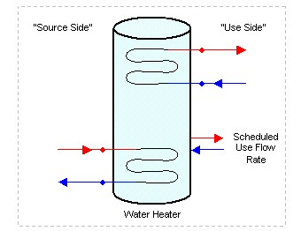
Figure 65. Water Heater Configuration
If the use side only consists of domestic hot water usage, a simple scheduled use flow rate can be specified in lieu of the full plant loop connections. The scheduled use flow rate can be used simultaneously with source side plant connections, but cannot be used with use side plant connections.
For stand-alone operation, there are no node connections to the plant loop on either source or use sides. The scheduled use flow rate determines all fluid exchange with the water tank.
There are currently two water heater objects in EnergyPlus:
n WaterHeater:Mixed
n WaterHeater:Stratified
There is also a compound object that uses the WaterHeater:Mixed as part of its strategy:
n WaterHeater:HeatPump
The WaterHeater:Mixed object simulates a well-mixed, single-node water tank. The WaterHeater:Stratified object simulates a stratified, multi-node water tank. Both water heater objects can be appropriate for simulating many types of water heaters and storage tanks, including gas and electric residential water heaters, and a variety of large commercial water heaters. Both objects share similar features, such as stand-alone operation, on- and off-cycle parasitic loads, and thermal losses to the zone. However, each object has its advantages which may make one water heater object more appropriate than the other depending on the application.
Advantages of WaterHeater:Mixed:
§ can simulate instantaneous/tankless water heaters
§ requires less input than the stratified tank
§ faster execution time than the stratified tank
§ adequate for modeling gas water heaters with no source connections.
Advantages of WaterHeater:Stratified:
§ better modeling of electric water heaters with two heating elements
§ better modeling of thermal storage applications which rely on stratification to improve heat transfer peformance.
The EIO file reports the industry standard ratings of Recovery Efficiency and Energy Factor for water heater objects. The rating method is based on the GAMA and 10CFR430 test procedures. Under certain input parameters, the rating method will not succeed and a warning message will be generated. Problems occur when inputs do not allow the tank to recover to the setpoint temperature within the test period. This can occur if the maximum heater capacity is undersized, or if the deadband temperature difference is large enough that the first draw of the test does not trigger the heater to come on. In either case, the Recovery Efficiency test will not compute properly because recovery to the setpoint was not achieved.
Standard ratings for storage-only water tanks (Heater Maximum Capacity = 0) cannot be calculated and do not report anything in the EIO file.
The WaterHeater:Mixed object analytically solves the differential equation governing the energy balance of the water tank. Within a timestep, conditions are solved separately for when the heater element or burner is "on" (on-cycle) and when it is "off" (off-cycle). This approach allows ambient losses and parasitic loads to be divided into on-cycle and off-cycle effects and accounted for in detail.
For losses to the ambient environment, the ambient air temperature can be taken from a schedule, a zone, or the exterior. When used with a zone, a fraction of the skin losses can be added to the zone heat balance as internal heat gains.
Control options allow the heater to cycle or modulate to meet the load. When cycling, the heater element or burner is either on or off. The heater remains fully on while heating the tank up to the setpoint temperature. When the setpoint is reached, the heater turns off. The heater remains off until the tank temperature falls below the "cut-in" temperature, i.e., the setpoint temperature minus the deadband temperature difference. The heater continuously cycles on and off to maintain the tank temperature within the deadband. Most storage-tank water heaters cycle.
When modulating, the heater power varies between the maximum and minimum heater capacities. The heater stays on as long as the required total demand is above the minimum capacity. Below the minimum capacity, the heater will begin to cycle on and off based on the deadband temperature difference. Equipment is usually designed and rated to avoid this condition. Most tankless/instantaneous water heaters modulate.
The name of the WaterHeater:Mixed object.
The volume of the storage tank [m3]. This field is autosizable if used with a Water Heater:Sizing object. Although this field is allowed to go down to zero, even so-called "tankless" water heaters have some volume of water that is maintained around the heating elements or in the heat exchanger, typically around 0.00379 m3 (1 gallon).
The reference to the schedule object specifying the hot water temperature setpoint [°C]. Also known as the "cut-out" temperature.
The delta temperature difference [Δ°C] between the setpoint and the "cut-in" temperature at which the heater will turn on. In other words, the "cut-in" temperature is Setpoint – Deadband.
The temperature [°C] at which the tank water becomes dangerously hot and is vented through boiling or an automatic safety. The tank temperature will never exceed the maximum. Any extra heat added to the tank is immediately vented. Note: The maximum temperature must be greater than the setpoint temperature at all times.
The control type can be Cycle or Modulate. Cycle is appropriate for most storage tank-type water heaters. Modulate is appropriate for most instantaneous/tankless water heaters.
The maximum heat rate [W] that can be supplied to the water, probably the same as the "nominal" capacity. This field is autosizable if used with a Water Heater:Sizing object.
The minimum heat rate [W] that can be supplied to the water. This field is only used when the Heater Control Type is Modulate. If the total demand rate for heating is less than the minimum, even a modulating water heater will begin to cycle.
NOT YET IMPLEMENTED.
NOT YET IMPLEMENTED.
The type of fuel used for heating. The fuel type can be Electricity, NaturalGas, PropaneGas, FuelOil#1, FuelOil#2, Coal, Diesel, Gasoline, Steam, or DistrictHeating.
The thermal conversion efficiency from fuel energy to heat energy for the heater element or burner. This is not the same as the overall efficiency of the water heater.
The reference to the curve object that relates the overall efficiency of the water heater to the Runtime Fraction (if Control Type Cycle) or Part Load Ratio (if Control Type Modulate). This is an additional multiplier applied to the Heater Thermal Efficiency to compute fuel energy use. The Part Load Factor Curve should not have a value less than 0.1 in the domain from 0 to 1. If the Part Load Factor Curve accounts for ambient losses and/or parasitic fuel consumption, these effects should not also be input into the related fields in this object as that would result in double-counting.
Off-cycle parasitics include parts of the water heater that consume fuel when the heater is off, for example, a pilot light, or stand-by electronic control circuits. The fuel consumption rate [W] is strictly the total fuel that is consumed by all of the off-cycle parasitics.
The type of fuel used by the off-cycle parasitics. The fuel type can be Electricity, NaturalGas, PropaneGas, FuelOil#1, FuelOil#2, Coal, Diesel, Gasoline, Steam, or DistrictHeating. The fuel type can be the same or different from the Heater Fuel Type.
The fraction of off-cycle parasitic fuel energy that is converted to heat energy that ends up in the tank water. For example, a pilot light would deliver most of its heat to the tank water, as long as the thermal conversion efficiency must be taken into account, so perhaps 0.80 is reasonable. Electronic control circuits, on the other hand, do not add any heat to the tank and should be 0.
On-cycle parasitics include parts of the water heater that consume fuel when the heater is on, for example, an induction fan, or stand-by electronic control circuits. The fuel consumption rate [W] is strictly the total fuel that is consumed by all of the on-cycle parasitics.
The type of fuel used by the on-cycle parasitics. The fuel type can be Electricity, NaturalGas, PropaneGas, FuelOil#1, FuelOil#2, Coal, Diesel, Gasoline, Steam, or DistrictHeating. The fuel type can be the same or different from the Heater Fuel Type.
The fraction of on-cycle parasitic fuel energy that is converted to heat energy that ends up in the tank water. For example, an induction fan might (maybe) deliver a small fraction of its energy to the tank water for a value of 0.05. Electronic control circuits, on the other hand, do not add any heat to the tank and should be 0.
The Ambient Temperature Indicator specifies how the ambient air temperature will be indicated. The field can be Schedule, Zone, or Outdoors. If Scheduleis used, the Ambient Temperature Schedule field provides the ambient temperature. If ZONE is used, the zone air temperature of the zone specified in the Ambient Temperature Zone field provides the ambient temperature. If EXTERIOR is used, the outdoor dry-bulb air temperature provides the ambient temperature.
The reference to the schedule object specifying the ambient air temperature around the tank for skin losses. This field is only used if Ambient Temperature Indicator is Schedule.
The reference to the zone object specifying the ambient air temperature around the tank for skin losses. This field is only used if Ambient Temperature Indicator is Zone.
This optional alpha field specifies the outdoor air node name used to define the ambient conditions surrounding the water heater tank. This field is applicable only when the Ambient Temperature Indicator is specified as OutdoorAir:Node, otherwise this field should be left blank. The node name specified must also be specified in an OutdoorAir:Node object where the height of the node is taken into consideration when calculating outdoor air conditions from the weather data. Alternately, the node name may be specified in an OutdoorAir:NodeList object where the outdoor air conditions are taken directly from the weather data.
The loss coefficient [W/K] to the ambient air temperature. Often this coefficient is identical to the "UA" for skin losses. However, it can also be used to model the loss effects of the flue in a combustion water heater, in addition to the skin losses.
If the Ambient Temperature Indicator is Zone, this field adds the specified fraction of the off-cycle losses to the zone heat balance as an internal gain.
The loss coefficient [W/K] to the ambient air temperature. Often this coefficient is identical to the "UA" for skin losses. If the loss effects of the flue are being modeled in the Off-Cycle Loss Coefficient, than this field would have a different value accounting only for the skin losses.
If the Ambient Temperature Indicator is Zone, this field adds the specified fraction of the on-cycle losses to the zone heat balance as an internal gain.
The peak flow rate [m3/s] of domestic hot water usage for stand-alone operation, i.e., without plant loop node connections. The peak value is multiplied by the Use Flow Rate Fraction Schedule. If there are node connections, this field is not used.
The reference to the schedule object specifiying the current fraction of Peak Volumetric Use Flow Rate of domestic hot water usage for stand-alone operation.
The reference to the schedule object specifying the cold water temperature [°C] from the supply mains that makes up for the hot water lost down the drain. If blank, water temperatures are calculated by the Site:WaterMainsTemperature object. This field is for stand-alone operation only. If there are node connections, this field is not used.
The inlet node connection to the plant loop for the use side of the water heater. Typically the use side draws hot water from the tank and returns cooler water.
The outlet node connection to the plant loop for the use side of the water heater. Typically the use side draws hot water from the tank and returns cooler water.
This field specifies the heat transfer effectiveness between the use side water and the tank water. If the effectiveness is set to 1 then complete heat transfer occurs, simulating perfect mixing of the use side water and the tank water. If the effectiveness is lower, then the use side outlet water temperature will not be as hot as the tank water, simulating a heat exchanger.
The inlet node connection to the plant loop for the source side of the water heater. Typically the source side draws cold water from the tank and returns warmer water. The source side volume flow rate is obtained from the plant loop. The magnitude of the flow rates through the source side can be controlled by setting the Maximum Branch Flow Rate field in the Branch object that connects the source inlet node.
The outlet node connection to the plant loop for the source side of the water heater. Typically the source side draws cold water from the tank and returns warmer water.
This field specifies the heat transfer effectiveness between the source side water and the tank water. If the effectiveness is set to 1 then complete heat transfer occurs, simulating perfect mixing of the source side water and the tank water. If the effectiveness is lower, then the source side outlet water temperature will not be as hot as the tank water, simulating a heat exchanger.
This field is optional and is used to specify the design flow rate through the Use Side of the water heater. The volumetric design flow rate is specified in m3/s. The field is needed when the Use Side is connected to a plant loop. The field can be autosized. If autosized, then the input file should include a Plant Sizing object for the plant loop. Sizing results are reported in the EIO file.
This field is optional and is used to specify the design flow rate through the Source Side of the water heater. The volumetric design flow rate is specified in m3/s. The field is needed when the Source Side is connected to a plant loop. The field can be autosized. If autosized, then the input file should include a Plant Sizing object for the plant loop. Sizing results are reported in the EIO file.
This field is optional and is used to provide a design parameter for autosizing design flow rates when the water heater is connected to the demand side of a plant loop. The recovery time is expressed in hours. This is the time that the entire volume of the tank can be heated from 14.4ºC to 57.2ºC (58ºF to 135ºF) with an inlet temperature defined as the exit temperature in the associated Plant Sizing object. The default is 1.5 hours. The calculation is based on log-mean temperature difference (LMTD) and includes the heat transfer effectiveness factor entered above.
WaterHeater:Mixed, ! Stand-alone electric, outdoor example
Outdoor Electric Tank, !- Name
0.151, !- Tank Volume {m3}
Hot Water Setpoint Temp Schedule, !- Setpoint Temperature Schedule
2.0, !- Deadband Temperature Difference {deltaC}
82.2222, !- Maximum Temperature Limit {C}
Cycle, !- Heater Control Type {Cycle | Modulate}
11712, !- Heater Maximum Capacity {W}
, !- Heater Minimum Capacity {W}
, !- Heater Ignition Minimum Flow Rate {m3/s}
, !- Heater Ignition Delay {s}
ELECTRICITY, !- Heater Fuel Type
0.95, !- Heater Thermal Efficiency
, !- Part Load Factor Curve
15, !- Off-Cycle Parasitic Fuel Consumption Rate {W}
ELECTRICITY, !- Off-Cycle Parasitic Fuel Type
0, !- Off-Cycle Parasitic Heat Fraction To Tank
15, !- On-Cycle Parasitic Fuel Consumption Rate {W}
ELECTRICITY, !- On-Cycle Parasitic Fuel Type
0, !- On-Cycle Parasitic Heat Fraction To Tank
Outdoors, !- Ambient Temperature Indicator {Schedule | Zone | Outdoors}
, !- Ambient Temperature Schedule
, !- Ambient Temperature Zone
2.36, !- Off-Cycle Loss Coefficient To Ambient Temperature {W/K}
, !- Off-Cycle Loss Fraction To Zone
2.36, !- On-Cycle Loss Coefficient To Ambient Temperature {W/K}
, !- On-Cycle Loss Fraction To Zone
0.000379, !- Peak Volumetric Use Flow Rate {m3/s}
Hot Water Demand Schedule, !- Use Flow Rate Fraction Schedule
Constant Mains Temp Schedule; !- Cold Water Supply Temperature Schedule
WaterHeater:Mixed, ! Stand-alone electric, tankless example
Tankless, !- Name
0.003785, !- Tank Volume {m3}
Hot Water Setpoint Temp Schedule, !- Setpoint Temperature Schedule
, !- Deadband Temperature Difference {deltaC}
82.2222, !- Maximum Temperature Limit {C}
Modulate, !- Heater Control Type {Cycle | Modulate}
11712, !- Heater Maximum Capacity {W}
0, !- Heater Minimum Capacity {W}
, !- Heater Ignition Minimum Flow Rate {m3/s}
, !- Heater Ignition Delay {s}
ELECTRICITY, !- Heater Fuel Type
0.95, !- Heater Thermal Efficiency
, !- Part Load Factor Curve
10, !- Off-Cycle Parasitic Fuel Consumption Rate {W}
ELECTRICITY, !- Off-Cycle Parasitic Fuel Type
0, !- Off-Cycle Parasitic Heat Fraction To Tank
30, !- On-Cycle Parasitic Fuel Consumption Rate {W}
ELECTRICITY, !- On-Cycle Parasitic Fuel Type
0, !- On-Cycle Parasitic Heat Fraction To Tank
Schedule, !- Ambient Temperature Indicator {Schedule | Zone | Outdoors}
Hot Water Ambient Temp Schedule, !- Ambient Temperature Schedule
, !- Ambient Temperature Zone
, !- Off-Cycle Loss Coefficient To Ambient Temperature {W/K}
, !- Off-Cycle Loss Fraction To Zone
, !- On-Cycle Loss Coefficient To Ambient Temperature {W/K}
, !- On-Cycle Loss Fraction To Zone
0.000379, !- Peak Volumetric Use Flow Rate {m3/s}
Hot Water Demand Schedule, !- Use Flow Rate Fraction Schedule
; !- Cold Water Supply Temperature Schedule
WaterHeater:Mixed, ! Plant loop connected, gas example
Water Heater, !- Name
0.454, !- Tank Volume {m3}
Hot Water Setpoint Temp Schedule, !- Setpoint Temperature Schedule
5.0, !- Deadband Temperature Difference {deltaC}
82.2222, !- Maximum Temperature Limit {C}
Cycle, !- Heater Control Type {Cycle | Modulate}
2000, !- Heater Maximum Capacity {W}
, !- Heater Minimum Capacity {W}
, !- Heater Ignition Minimum Flow Rate {m3/s}
, !- Heater Ignition Delay {s}
NATURALGAS, !- Heater Fuel Type
0.80, !- Heater Thermal Efficiency
, !- Part Load Factor Curve
, !- Off-Cycle Parasitic Fuel Consumption Rate {W}
, !- Off-Cycle Parasitic Fuel Type
, !- Off-Cycle Parasitic Heat Fraction To Tank
, !- On-Cycle Parasitic Fuel Consumption Rate {W}
, !- On-Cycle Parasitic Fuel Type
, !- On-Cycle Parasitic Heat Fraction To Tank
Schedule, !- Ambient Temperature Indicator {Schedule | Zone | Outdoors}
Hot Water Ambient Temp Schedule, !- Ambient Temperature Schedule
, !- Ambient Temperature Zone
5.0, !- Off-Cycle Loss Coefficient To Ambient Temperature {W/K}
, !- Off-Cycle Loss Fraction To Zone
5.0, !- On-Cycle Loss Coefficient To Ambient Temperature {W/K}
, !- On-Cycle Loss Fraction To Zone
, !- Peak Volumetric Use Flow Rate {m3/s}
, !- Use Flow Rate Fraction Schedule
, !- Cold Water Supply Temperature Schedule
Water Heater Use Inlet Node, !- Use Side Inlet Node
Water Heater Use Outlet Node, !- Use Side Outlet Node
1.0, !- Use Side Effectiveness
Water Heater Source Inlet Node, !- Source Side Inlet Node
Water Heater Source Outlet Node, !- Source Side Outlet Node
1.0; !- Source Side Effectiveness
WaterHeater:Mixed,
Indirect Water Heater, !- Name
1.00, !- Tank Volume {m3}
Hot Water Setpoint Temperature Schedule, !- Setpoint Temperature Schedule
5.0, !- Deadband Temperature Difference {deltaC}
82.2222, !- Maximum Temperature Limit {C}
Cycle, !- Heater Control Type
0.0, !- Heater Maximum Capacity {W}
, !- Heater Minimum Capacity {W}
, !- Heater Ignition Minimum Flow Rate {m3/s}
, !- Heater Ignition Delay {s}
ELECTRIC, !- Heater Fuel Type
0.8, !- Heater Thermal Efficiency
, !- Part Load Factor Curve
, !- Off-Cycle Parasitic Fuel Consumption Rate {W}
, !- Off-Cycle Parasitic Fuel Type
, !- Off-Cycle Parasitic Heat Fraction To Tank
, !- On-Cycle Parasitic Fuel Consumption Rate {W}
, !- On-Cycle Parasitic Fuel Type
, !- On-Cycle Parasitic Heat Fraction To Tank
Zone, !- Ambient Temperature Indicator
, !- Ambient Temperature Schedule
SPACE5-1, !- Ambient Temperature Zone
, !- Ambient Temperature Outside Air Node
5.0, !- Off-Cycle Loss Coefficient To Ambient Temperature {W/K}
, !- Off-Cycle Loss Fraction To Zone
5.0, !- On-Cycle Loss Coefficient To Ambient Temperature {W/K}
, !- On-Cycle Loss Fraction To Zone
, !- Peak Volumetric Use Flow Rate {m3/s}
, !- Use Flow Rate Fraction Schedule
, !- Cold Water Supply Temperature Schedule
SHWSys1 Pump-SHWSys1 Water HeaterNode, !- Use Side Inlet Node
SHWSys1 Supply Equipment Outlet Node, !- Use Side Outlet Node
1.0, !- Use Side Effectiveness
Indirect Water Heater SrcSideInletNode, !- Source Side Inlet Node
Indirect Water Heater SrcSideOutletNode, !- Source Side Outlet Node
0.9, !- Source Side Effectiveness
autosize, !- Use Side Design Flow Rate
autosize, !- Source Side Design Flow Rate
1.0; !- Indirect Water Heating Recovery Time
The following output variables are reported for the WaterHeater:Mixed object:
HVAC,Average,Water Heater Tank Temperature [C]
HVAC,Average,Water Heater Final Tank Temperature [C]
HVAC,Average,Water Heater Loss Rate [W]
HVAC,Sum,Water Heater Loss Energy [J]
HVAC,Average,Water Heater Use Flow Rate [kg/s]
HVAC,Average,Water Heater Use Inlet Temperature [C]
HVAC,Average,Water Heater Use Outlet Temperature [C]
HVAC,Average,Water Heater Use Rate [W]
HVAC,Sum,Water Heater Use Energy [J]
HVAC,Average,Water Heater Source Flow Rate [kg/s]
HVAC,Average,Water Heater Source Inlet Temperature [C]
HVAC,Average,Water Heater Source Outlet Temperature [C]
HVAC,Average,Water Heater Source Rate [W]
HVAC,Sum,Water Heater Source Energy [J]
HVAC,Average,Water Heater Off-Cycle Parasitic Heat Rate To Tank [W]
HVAC,Sum,Water Heater Off-Cycle Parasitic Heat Energy To Tank [J]
HVAC,Average,Water Heater On-Cycle Parasitic Heat Rate To Tank [W]
HVAC,Sum,Water Heater On-Cycle Parasitic Heat Energy To Tank [J]
HVAC,Average,Water Heater Total Demand Rate [W]
HVAC,Sum,Water Heater Total Demand Energy [J]
HVAC,Average,Water Heater Heating Rate [W]
HVAC,Sum,Water Heater Heating Energy [J]
HVAC,Average,Water Heater Unmet Demand Rate [W]
HVAC,Sum,Water Heater Unmet Demand Energy [J]
HVAC,Average,Water Heater Venting Rate [W]
HVAC,Sum,Water Heater Venting Energy [J]
HVAC,Average,Water Heater Net Heat Tranfer Rate [W]
HVAC,Sum,Water Heater Net Heat Tranfer Energy [J]
HVAC,Sum,Water Heater Cycle On Count []
HVAC,Average,Water Heater Runtime Fraction []
HVAC,Average,Water Heater Part Load Ratio []
HVAC,Average,Water Heater <Fuel Type> Consumption Rate [W]
HVAC,Sum,Water Heater <Fuel Type>Consumption [J]
HVAC,Average,Water Heater Off-Cycle Parasitic <Fuel Type> Consumption Rate [W]
HVAC,Sum,Water Heater Off-Cycle Parasitic <Fuel Type> Consumption [J]
HVAC,Average,Water Heater On-Cycle Parasitic <Fuel Type> Consumption Rate [W]
HVAC,Sum,Water Heater On-Cycle Parasitic <Fuel Type> Consumption [J]
HVAC,Average,Water Heater Water Consumption Rate [m3/s]
HVAC,Sum,Water Heater Water Consumption [m3]
The average water tank temperature.
The final water tank temperature at the end of the system timestep. If reported at the "Detailed" interval, this report variable can be used to verify an exact energy balance on the water heater. Also see the report variable: Water Heater Net Heat Transfer Energy.
The average heat loss rate due to the off- and on-cycle loss coefficients to the ambient temperature.
The heat loss energy due to the off- and on-cycle loss coefficients to the ambient temperature.
The use side mass flow rate. If stand-alone, this is the scheduled use flow rate.
The inlet temperature on the use side.
The outlet temperature on the use side.
The average heat transfer rate between the use side water and the tank water.
The heat transfer energy between the use side water and the tank water.
The source side mass flow rate. If in stand-alone operation, this is 0.
The inlet temperature on the source side.
The outlet temperature on the source side.
The average heat transfer rate between the source side water and the tank water.
The heat transfer energy between the source side water and the tank water.
The average heat gain rate to the tank water due to off-cycle parasitics.
The heat gain energy to the tank water due to off-cycle parasitics.
The average heat gain rate to the tank water due to on-cycle parasitics.
The heat gain energy to the tank water due to on-cycle parasitics.
The average heating rate demanded to maintain the setpoint temperature.
The heating energy demanded to maintain the setpoint temperature.
The average heating rate supplied by the heater element or burner.
The heating energy supplied by the heater element or burner.
The average heating rate unmet by the heater element or burner. The difference between the Total Demand Rate and the Heating Rate.
The heating energy unmet by the heater element or burner. The difference between the Total Demand Energy and the Heating Energy.
The average venting rate to keep the tank below the Maximum Temperature Limit.
The venting energy to keep the tank below the Maximum Temperature Limit.
The average net heat transfer rate when considering all losses and gains.
The net heat transfer energy when considering all losses and gains.
The number of times that the heater turned on in the time period.
The fraction of the time period that the heater was running.
The fraction of the Heater Maximum Capacity.
The average fuel consumption rate for the heater element or burner.
The fuel consumption energy for the heater element or burner.
The average fuel consumption rate for the off-cycle parasitics.
The fuel consumption energy for the off-cycle parasitics.
The average fuel consumption rate for the on-cycle parasitics.
The fuel consumption energy for the on-cycle parasitics.
The water consumption rate for the use side, if in stand-alone operation.
The water consumption for the use side, if in stand-alone operation.
The WaterHeater:Stratified object divides the water tank into multiple nodes of equal volume. The nodes are coupled by vertical conduction effects, internode fluid flow, and temperature inversion mixing. The object simultaneously solves the differential equations governing the energy balances on the nodes using a numerical method. The system timestep is divided into many small substeps that allow the simulation to capture events that occur on a very short time scale. This approach allows ambient losses and parasitic loads to be divided into on-cycle and off-cycle effects and accounted for in detail.
For losses to the ambient environment, the ambient air temperature can be taken from a schedule, a zone, or the exterior. When used with a zone, a fraction of the skin losses can be added to the zone heat balance as internal heat gains.
The WaterHeater:Stratified object allows two heating elements to be simulated. The two elements can cycle on and off to maintain the node temperature within the deadband. The Heater Priority Control field determines how the heaters work together. There are two options: MasterSlave or Simultaneous. In the MasterSlave option, Heater 1 is the master and Heater 2 is the slave. That is, both heaters are not allowed to turn on at the same time. If the thermostats ask for heat at both Heater 1 and 2, only Heater 1 will turn on. Once Heater 1 has met the set point, it turns off and Heater 2 can turn on, if necessary. In the Simultaneousoption, Heater 1 and Heater 2 can turn on and off independently. Autosizing is available for only Heater 1.
The name of the WaterHeater:Stratified object.
Allows you to specify a user-defined end-use subcategory, e.g., "Laundry", "Dish Washing", etc. A new meter for reporting is created for each unique subcategory (ref: Report Meter). Subcategories are also reported in the ABUPS table under the "Water Systems" end-use category. If this field is omitted or blank, the water use will be assigned to the "General" end-use subcategory.
The actual volume [m3] of fluid in the tank. This field is autosizable if used with a Water Heater:Sizing object. The actual volume is typically not equal to the nominal volume specified by the manufacturer. Actual volume is almost always 10% lower for electric water heaters, and 5% lower for gas water heaters (Burch and Erickson 2004).
Burch, J., and P. Erickson. 2004. "Using Ratings Data to Derive Simulation-Model Inputs for Storage-Tank Water Heaters". Proceedings of the Solar 2004 Conference, 11-14 July 2004, Portland, Oregon, American Solar Energy Society (ASES), pp. 393-398.
The height [m] of the tank. For the HorizontalCylinder shape (see below) the height of the tank is the measure in the axial direction, i.e., the height if you were to stand the cylinder up on its end. This field is autosizable if used with a Water Heater:Sizing object.
The tank shape determines the size and skin losses of the stratified nodes. There are three options: VerticalCylinder, HorizontalCylinder, and Other.
VerticalCylinder describes most upright residential water heaters.
HorizontalCylinder describes a few specialty water heaters and large commercial storage tanks. HorizontalCylinder can also be used to model an outdoor storage tank located above a solar collector in a thermosiphon configuration. HorizontalCylinder implies that the tank is divided into nodes of equal mass, but not equal height.
Other describes water heaters or storage tanks that have a uniform horizontal cross-section, but are not cylinders, e.g., a cuboid or other shape. The length of the perimeter is then specified by the Tank Perimeter field.
If blank, the default shape is VerticalCylinder.
The length of the tank perimeter [m]. This field is only used if Tank Shape is Other.
The temperature [°C] at which the tank water becomes dangerously hot and is vented through boiling or an automatic safety. The tank temperature will never exceed the maximum. Any extra heat added to the tank is immediately vented. Note: The maximum temperature must be greater than the setpoint temperature at all times.
The heater priority control determines how Heater 1 and Heater 2 work together. There are two options: MasterSlave or Simultaneous. In the MasterSlave option, Heater 1 is the master and Heater 2 is the slave. In most residential electric water heaters, the heaters operate in a MasterSlave relationship. That is, both heaters are not allowed to turn on at the same time. If the thermostats ask for heat at both Heater 1 and 2, only Heater 1 will turn on. Once Heater 1 has met the set point, it turns off and Heater 2 can turn on, if necessary. In other words, only one heater can be on at any time, and Heater 1 is always has priority over Heater 2.
In the Simultaneous option, Heater 1 and Heater 2 can turn on and off independently.
If blank, the default is MasterSlave.
The reference to the schedule object specifying the hot water temperature set point [°C] for Heater 1. Also known as the "cut-out" temperature.
The delta temperature difference [Δ°C] between the set point and the "cut-in" temperature at which Heater 1 will turn on. In other words, the "cut-in" temperature is Set Point – Deadband.
The heat rate [W] supplied to the water for Heater 1, probably the same as the "nominal" capacity. For residential electric water heaters, heating elements are usually 4500 W. This field is autosizable if used with a Water Heater:Sizing object.
The height [m] of Heater 1 in the tank.
The reference to the schedule object specifying the hot water temperature set point [°C] for Heater 2. Also known as the "cut-out" temperature.
The delta temperature difference [Δ°C] between the set point and the "cut-in" temperature at which Heater 2 will turn on. In other words, the "cut-in" temperature is Set Point – Deadband.
The heat rate [W] supplied to the water for Heater 1, probably the same as the "nominal" capacity. For residential electric water heaters, heating elements are usually 4500 W.
The height [m] of Heater 2 in the tank.
The type of fuel used for both Heaters 1 and 2. The fuel type can be Electricity, NaturalGas, PropaneGas, FuelOil#1, FuelOil#2, Coal, Diesel, Gasoline, Steam, or DistrictHeating.
The thermal conversion efficiency from fuel energy to heat energy for the heater element or burner (for both Heaters 1 and 2). This is not the same as the overall efficiency of the water heater.
Off-cycle parasitics include parts of the water heater that consume fuel when the heater is off, for example, a pilot light, or stand-by electronic control circuits. The fuel consumption rate [W] is strictly the total fuel that is consumed by all of the off-cycle parasitics.
The type of fuel used by the off-cycle parasitics. The fuel type can be Electricity, NaturalGas, PropaneGas, FuelOil#1, FuelOil#2, Coal, Diesel, Gasoline, Steam, or DistrictHeating. The fuel type can be the same or different from the Heater Fuel Type.
The fraction of off-cycle parasitic fuel energy that is converted to heat energy that ends up in the tank water. For example, a pilot light would deliver most of its heat to the tank water, as long as the thermal conversion efficiency must be taken into account, so perhaps 0.80 is reasonable. Electronic control circuits, on the other hand, do not add any heat to the tank and should be 0.
The height [m] where any off-cycle parasitic heat gains are added to the tank.
On-cycle parasitics include parts of the water heater that consume fuel when the heater is on, for example, an induction fan, or stand-by electronic control circuits. The fuel consumption rate [W] is strictly the total fuel that is consumed by all of the on-cycle parasitics.
The type of fuel used by the on-cycle parasitics. The fuel type can be Electricity, NaturalGas, PropaneGas, FuelOil#1, FuelOil#2, Coal, Diesel, Gasoline, Steam, or DistrictHeating. The fuel type can be the same or different from the Heater Fuel Type.
The fraction of on-cycle parasitic fuel energy that is converted to heat energy that ends up in the tank water. For example, an induction fan might (maybe) deliver a small fraction of its energy to the tank water for a value of 0.05. Electronic control circuits, on the other hand, do not add any heat to the tank and should be 0.
The height [m] where any on-cycle parasitic heat gains are added to the tank.
The Ambient Temperature Indicator specifies how the ambient air temperature will be indicated. The field can be Schedule, Zone, or Outdoors. If Schedule is used, the Ambient Temperature Schedule value provides the ambient temperature. If Zone is used, the zone air temperature of the zone specified in the Ambient Temperature Zone field provides the ambient temperature. If Outdoors is used, the outdoor dry-bulb air temperature of the outdoor air node specified in the Ambient Temperature OutdoorAir:Node field provides the ambient temperature.
The reference to the schedule object specifying the ambient air temperature around the tank for skin losses. This field is only used if Ambient Temperature Indicator is Schedule.
The reference to the zone object specifying the ambient air temperature around the tank for skin losses. This field is only used if Ambient Temperature Indicator is Zone.
The reference to the outdoor air node specifying the ambient air temperature around the tank for skin losses. An outdoor air node can be defined by an OutdoorAir:Node object or OutdoorAir:NodeList object. This field is only used if Ambient Temperature Indicator is Outdoors.
The uniform skin loss coefficient [W/m2-K] or U-Value of the tank to the ambient air temperature. The uniform skin loss accounts for the tank insulation and applies during both off- and on-cycle operation. The overall losses at any particular node can be further modified using the Additional Loss Coefficient fields to account for thermal shorting due to pipe penetrations, water heater feet, and any other loss effects.
If the Ambient Temperature Indicator is Zone, this field adds the specified fraction of the skin losses to the zone heat balance as an internal gain.
The off-cycle flue loss coefficient [W/K] to the ambient air temperature. This field mainly applies to gas water heaters that have a flue.
If the Ambient Temperature Indicator is Zone, this field adds the specified fraction of the off-cycle flue losses to the zone heat balance as an internal gain.
The peak flow rate [m3/s] of domestic hot water usage for stand-alone operation, i.e., without plant loop node connections. The peak value is multiplied by the Use Flow Rate Fraction Schedule. If there are node connections, this field is not used.
The reference to the schedule object specifiying the current fraction of Peak Volumetric Use Flow Rate of domestic hot water usage for stand-alone operation. If blank, the fraction defaults to 1.0 at all times.
The reference to the schedule object specifying the cold water temperature [°C] from the supply mains that makes up for the hot water lost down the drain. If blank, water temperatures are calculated by the Site:WaterMainsTemperature object. This field is for stand-alone operation only. If there are node connections, this field is not used.
The inlet node connection to the plant loop for the use side of the water heater. Typically the use side draws hot water from the tank and returns cooler water.
The outlet node connection to the plant loop for the use side of the water heater. Typically the use side draws hot water from the tank and returns cooler water.
This field specifies the heat transfer effectiveness between the use side water and the tank water. If the effectiveness is set to 1 then complete heat transfer occurs, simulating perfect mixing of the use side water and the tank water. If the effectiveness is less than 1.0, then the use side outlet water temperature will not be as hot as the tank water at the outlet node, simulating an external heat exchanger that is indirectly coupled to the water heater tank.
The height of the use side inlet to the tank. If blank, the inlet defaults to the bottom of the tank. The inlet height cannot be higher than the tank height.
The height of the use side outlet from the tank. If blank or autocalculate, the inlet defaults to the top of the tank. The outlet height cannot be higher than the tank height.
The inlet node connection to the plant loop for the source side of the water heater. Typically the source side draws cold water from the tank and returns warmer water.
The outlet node connection to the plant loop for the source side of the water heater. Typically the source side draws cold water from the tank and returns warmer water.
This field specifies the heat transfer effectiveness between the source side water and the tank water. If the effectiveness is set to 1 then complete heat transfer occurs, simulating perfect mixing of the source side water and the tank water. If the effectiveness is less than 1.0, then the source side outlet water temperature will be higher than the tank water at the outlet node, simulating an external heat exchanger that is indirectly coupled to the water heater tank.
The height of the source side inlet to the tank. If blank or autocalculate, the inlet defaults to the top of the tank. The inlet height cannot be higher than the tank height.
The height of the source side outlet from the tank. If blank, the inlet defaults to the bottom of the tank. The outlet height cannot be higher than the tank height.
The inlet mode of entering fluid from the use and source sides. There are two options: Fixed or Seeking. In Fixed mode, the fluid enters at the fixed heights specified above. In Seeking mode, the fluid "seeks out" the stratified node that is closest to the inlet temperature and adds all flow to that node. The Seekingbmode provides maximum stratification. The default is Fixed.
This field is optional and is used to specify the design flow rate through the Use Side of the water heater. The volumetric design flow rate is specified in m3/s. The field is needed when the Use Side is connected to a plant loop. The field can be autosized. If autosized, then the input file should include a Plant Sizing object for the plant loop. Sizing results are reported in the EIO file.
This field is optional and is used to specify the design flow rate through the Source Side of the water heater. The volumetric design flow rate is specified in m3/s. The field is needed when the Source Side is connected to a plant loop. The field can be autosized. If autosized, then the input file should include a Plant Sizing object for the plant loop. Sizing results are reported in the EIO file.
This field is optional and is used to provide a design parameter for autosizing design flow rates when the water heater is connected to the demand side of a plant loop. The recovery time is expressed in hours. This is the time that the entire volume of the tank can be heated from 14.4ºC to 57.2ºC (58ºF to 135ºF) with an inlet temperature defined as the exit temperature in the associated Plant Sizing object. The default is 1.5 hours. The calculation is based on log-mean temperature difference (LMTD) and includes the heat transfer effectiveness factor entered above.
The number of stratified nodes in the tank. There must be at least one node. The maximum number of nodes is 10, although this limit can be increased by editing the IDD.
An additional destratification conductivity [W/m-K] is added to the fluid conductivity of water (0.6 W/m-K) to account for vertical conduction effects along the inside of the tank wall, and perhaps other vertical components such as the flue, the cold water inlet pipe (dip tube), and the anode rod.
An additional loss coefficient [W/m-K] added to the skin losses for a given node to account for thermal shorting due to pipe penetrations, water heater feet, and any other loss effects.
WaterHeater:Stratified,
Electric Water Heater, !- Name
Water Heater, !- End-Use Subcategory
0.1893, !- Tank Volume {m3}
1.4, !- Tank Height {m}
VerticalCylinder, !- Tank Shape
, !- Tank Perimeter {m}
82.2222, !- Maximum Temperature Limit {C}
MasterSlave, !- Heater Priority
Hot Water Set Point Temp Schedule, !- Heater 1 Set Point Temperature Schedule
2.0, !- Heater 1 Deadband Temperature Difference {deltaC}
4500, !- Heater 1 Capacity {W} (Master)
1.0, !- Heater 1 Height {m}
Hot Water Set Point Temp Schedule, !- Heater 2 Set Point Temperature Schedule
5.0, !- Heater 2 Deadband Temperature Difference {deltaC}
4500, !- Heater 2 Capacity {W} (Slave)
0.0, !- Heater 2 Height {m}
ELECTRICITY, !- Heater Fuel Type
0.98, !- Heater Thermal Efficiency
10, !- Off-Cycle Parasitic Fuel Consumption Rate {W}
ELECTRICITY, !- Off-Cycle Parasitic Fuel Type
0, !- Off-Cycle Parasitic Heat Fraction To Tank
, !- Off-Cycle Parasitic Height {m}
10, !- On-Cycle Parasitic Fuel Consumption Rate {W}
ELECTRICITY, !- On-Cycle Parasitic Fuel Type
0, !- On-Cycle Parasitic Heat Fraction To Tank
, !- On-Cycle Parasitic Height {m}
SCHEDULE, !- Ambient Temperature Indicator
Ambient Temp Schedule, !- Ambient Temperature Schedule
, !- Ambient Temperature Zone
, !- Ambient Temperature Outdoor Air Node
0.846, !- Uniform Skin Loss Coefficient Per Unit Area To Ambient Temperature {W/m2-K}
, !- Skin Loss Fraction To Zone {}
, !- Off-Cycle Flue Loss Coefficient To Ambient Temperature {W/K}
, !- Off-Cycle Flue Loss Fraction To Zone {}
, !- Peak Volumetric Use Flow Rate {m3/s}
, !- Use Flow Rate Fraction Schedule
, !- Cold Water Supply Temperature Schedule
Water Heater Use Inlet Node, !- Use Side Inlet Node
Water Heater Use Outlet Node, !- Use Side Outlet Node
1.0, !- Use Side Effectiveness {}
, !- Use Side Inlet Height {m}
, !- Use Side Outlet Height {m}
, !- Source Side Inlet Node
, !- Source Side Outlet Node
, !- Source Side Effectiveness {}
, !- Source Side Inlet Height {m}
, !- Source Side Outlet Height {m}
FIXED, !- Inlet Mode {FIXED | SEEKING}
6, !- Number Of Nodes
0.1, !- Destratification Conductivity {W/m-K}
0.15, !- Node 1 Additional Loss Coefficient {W/K}
, !- Node 2 Additional Loss Coefficient {W/K}
, !- Node 3 Additional Loss Coefficient {W/K}
, !- Node 4 Additional Loss Coefficient {W/K}
, !- Node 5 Additional Loss Coefficient {W/K}
0.1; !- Node 6 Additional Loss Coefficient {W/K}
All of the output variables reported for the WaterHeater:Mixed object also apply to the WaterHeater:Stratified object, with several qualifications noted below:
The average water tank temperature, i.e., the average of all of the node average temperatures.
The final water tank temperature at the end of the system timestep, i.e., the average of all of the final node temperatures at the end of the system timestep. If reported at the "Detailed" interval, this report variable can be used to verify an exact energy balance on the water heater.
The total average heating rate supplied by Heater 1 plus Heater 2.
The total heating energy supplied by Heater 1 plus Heater 2.
The number of times that either Heater 1 or Heater 2 turned on in the time period.
The fraction of the time period that either Heater 1 or Heater 2 was running.
In addition, the WaterHeater:Stratified object also reports the following output variables:
HVAC,Average,Water Heater Heating Rate 1 [W]
HVAC,Average,Water Heater Heating Rate 2 [W]
HVAC,Sum,Water Heater Heating Energy 1 [J]
HVAC,Sum,Water Heater Heating Energy 2 [J]
HVAC,Sum,Water Heater Cycle On Count 1 []
HVAC,Sum,Water Heater Cycle On Count 2 []
HVAC,Average,Water Heater Runtime Fraction 1 []
HVAC,Average,Water Heater Runtime Fraction 2 []
HVAC,Average,Water Heater Node <x> Temperature [C]
HVAC,Average,Water Heater Final Node <x> Temperature [C]
The average heating rate supplied by Heater 1.
The average heating rate supplied by Heater 2.
The heating energy supplied by Heater 1.
The heating energy supplied by Heater 2.
The number of times that Heater 1 turned on in the time period.
The number of times that Heater 2 turned on in the time period.
The fraction of the time period that Heater 1 was running.
The fraction of the time period that Heater 2 was running.
The average node temperature.
The final node temperature at the end of the system timestep.
The WaterHeater:Sizing object is used to provide additional input data needed for designing tank volume and/or heater capacity for either the Mixed or Stratified water heaters. This object is only needed if volume or capacity is being automatically sized. There are no output variable associated with this object -- sizing results are reported to the EIO output file and some predefined summary reports.
A source of design input data for use with this object can be found in the current ASHRAE Handbook HVAC Applications chapter on Service Water Heating.
The idd entry for this object follows.
This field contains the unique name of the water heater being sized. This name should match the name of a Water Heater:Mixed or a Water Heater:Stratified input object defined elsewhere in the input file.
This field describes which of several methods are to be used for sizing the water heater. There are six possible choices and one of the following should be selected:
· PeakDraw. This design method uses the design flow rates of all the different demands placed on the water heater. The tank size is based on how long it can meet the demand and how quickly it can recover. The user enters the time in hours that the water heater can meet the demands. Only the hot water uses connected to an individual water heater are included in that water heater’s peak draw.
· ResidentialHUD-FHAMinimum This design method is based on minimum permissible water heater sizes (established by HUD-FHA in its Minimum Property Standards for One- and Two-Family Living Units, No. 4900.1-1982). The user enters the number of bathrooms and bedrooms in this input object. The smallest allowable water heater sizes are used.
· PerPerson This design method scales sizes based on the total number of people in all zones in the building. Each water heater in the model will be sized using the total (peak, design) number of people for the entire model. The number of people is determined from People objects defined elsewhere in the input file
· PerFloorArea This design method scales sizes based on the total floor area in all the zones in the building. Each water heater in the model will be sized using all the floor area in the model. The floor areas are determined from the geometry input elsewhere in the input file.
· PerUnit This design method scales sizes based on an arbitrary number of units. This can be used, for example, to size based on the number of rooms in a lodging building. The user provides the number of units in an input field in this object.
· PerSolarCollectorArea This design method scales tank volume based on the collector area for a solar hot water collector. The collector area is summed for all the collectors in the model and each tank is sized for the total. The collector area is determined from input for Solar Collectors defined elsewhere in the input file.
This field provides the time, in hours, that the tank’s volume can sustain a peak draw. It is used to size the tank’s volume which is the simple product of peak draw volume flow rate and the draw time. There is no assurance that the water will be at the desired temperature for the entire draw. This field is only used if the Design Mode is “PeakDraw.” The water heater must be connected to a full plant loop, be on the supply side, and the plant loop needs a Plant Sizing object.
This field provides the the time, in hours, that tank’s heater needs to recover the volume of the tank. The temperatures used to define recovery are a starting temperature of 14.4ºC (58ºF) and a final temperature of 57.2ºC (135ºF). This field is only used if the Design Mode is “PeakDraw.”
This field is used in case the water heater is indirectly heated by its source side connections and they are also autosized. Because of the complexity of such a water heater and the timing for when sizing calculation happen inside EnergyPlus, the Source side connection flow rates need to be reported before the tank’s volume can be sized to meet Peak Draw. This input field is used to provide a nominal tank volume to use temporarily while the flow connections are sized. This field is only used if the Design Mode is “PeakDraw” and the water heater has autosized plant connections on the demand side.
This field is used to enter the numer of bedrooms in the model. This field is only used if the Design Mode is “ResidentialHUD-FHAMinimum.”
This field is used to enter the number of bathrooms in the model. This field is only used if the Design Mode is “ResidentialHUD-FHAMinimum.”
This field is used to enter the tank’s storage volume on per-person basis. The units are m3/person. This field is only used if the Design Mode is “PerPerson.”
This field is used to enter the recovery capacity per person in units of m3/person/hr. This is the volume of water the heater can recover in one hour per person. Recovery is heating water from a starting temperature of 14.4ºC (58ºF) to a final temperature of 57.2ºC (135ºF). This field is only used if the Design Mode is “PerPerson.”
This field is used to enter the tank’s storage volume on a per-floor-area basis. The units are m3 /m2 (water/floor area). This field is only used if the Design Mode is “PerFloorArea.”
This field is used to enter the recovery capacity per floor area in units of m3/m2/hr. This is the volume water the heater can recover in an hour per floor area. Recovery is heating water from a starting temperature of 14.4ºC (58ºF) to a final temperature of 57.2ºC (135ºF). This field is only used if the Design Mode is “PerFloorArea.”
This field is used to enter the number of Units for use in sizing on per-Unit basis with the next two fields. This field is only used if the Design Mode is “PerUnit.” This can be used to account for any arbitrary item such as lodging rooms, desks, water fixtures, restrooms, etc.
This field is used to enter the tanks’ storage volume on per-Unit basis. The units are m3/Unit. The number of Units is entered in the previous field. This field is only used if the Design Mode is “PerUnit.”
This field is used to enter the recover capacity per Unit in units of m3/Unit/hr. This is the volume of water the heater can recover in an hour per Unit. Recovery is heating water from a starting temperature of 14.4ºC (58ºF) to a final temperature of 57.2ºC (135ºF). This field is only used if the Design Mode is “PerUnit.”
This field is used to enter the tank’s storage volume on per-solar-collector-area basis. The units are m3/m2. This field is only used if the Design Mode is “PerSolarCollectorArea.”
This field is used to scale the height of a stratified tank to preserve relative geometry for different size tanks. The Height Aspect Ratio is defined at the length scale in the vertical direction (height) divided by the length scale in the horizontal direction (diameter). This field is only used if the water heater being sized is a Water Heater:Stratified, the tank height has been set to Autosize, and the tank shape is set to VerticalCylinder. This field can be used with any Design Mode.
The heat pump water heater (HPWH) is a compound object consisting of a water heater tank (e.g., WaterHeater:Mixed), a direct expansion (DX) “coil” (i.e., an air-to-water DX compression system which includes a water heating coil, air coil, compressor, and water pump), and a fan to provide air flow across the air coil associated with the DX compression system. These objects work together to model a system which heats water using zone air, outdoor air, or a combination of zone and outdoor air as the primary heat source. Numerous configurations of tank location, inlet air source, and DX coil compressor location can be modeled, with one common configuration shown below.
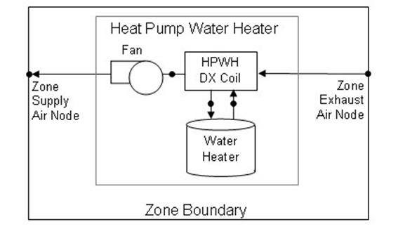
Figure 66. Schematic diagram for a heat pump water heater located in a zone
In this model, the heat pump water heater’s DX coil is considered the primary heat source and the water tank’s heater (element or burner) provides supplemental heat as necessary. The model also assumes that the heat pump’s fan and water pump cycle on and off with the compressor.
To model a heat pump water heater, the input data file must include some combination of the following objects depending on the configuration to be modeled:
· WaterHeater:HeatPump (required)
· WaterHeater:Mixed (required)
· Coil:WaterHeating:AirToWaterHeatPump (required)
· Fan:OnOff (required)
· ZoneHVAC:EquipmentList (when the HPWH draws some or all of its air from the zone, the heat pump water heater type and name must be in this list)
· ZoneHVAC:EquipmentConnections (when the HPWH draws some or all of its air from the zone, the HPWH air inlet and outlet node names must be provided in this object)
· OutdoorAir:NodeList (for HPWHs that use outdoor air as all or part of the heat source, the HPWH outdoor air node name must be provided in this list)
The input fields for the compound object are described in detail below:
This alpha field contains a unique user-assigned name for an instance of a heat pump water heater. Any reference to this heat pump water heater by another object will use this name.
This alpha field contains the name of the schedule (ref: Schedule) that denotes whether the heat pump compressor is available to operate during a given time period. A schedule value equal to 0 denotes that the heat pump compressor is off for that time period. A value other than 0 denotes that the heat pump compressor is available to operate during that time period. During times when the heat pump compressor is scheduled off, the heater (element or burner) in the water tank object operates based on its tank set point temperature schedule and the heat pump’s parasitic electric power is also off for that time period.
This alpha field contains the name of the schedule (ref: Schedule) that specifies the set point (or “cut-out”) temperature for the heat pump compressor. Temperature values used in this schedule should be in degrees Celsius. The heat pump compressor cycles off when the tank water reaches this set point temperature. Once the heat pump compressor cycles off, the tank water temperature floats downward until it falls below the set point temperature minus the dead band temperature difference defined below (i.e., the “cut-in” temperature). At this point, the heat pump compressor cycles on and remains on until the heat pump compressor set point temperature is reached.
This numeric field contains the dead band temperature difference in degrees Celsius. The heat pump compressor “cut-in” temperature is defined as the compressor set point temperature defined above minus this dead band temperature difference. The heat pump compressor cycles on when the water temperature in the tank falls below the “cut-in” temperature. The heat pump compressor remains on until the water temperature in the tank rises above the compressor set point (“cut-out”) temperature defined above. The dead band temperature difference must be greater than 0°C and less than or equal to 20°C. If this field is left blank, the default value is 5°C.
In this model, the heat pump water heater’s DX compression system is considered the primary heat source and the water tank’s heater (element or burner) provides supplemental heat as necessary. Therefore, the cut-in temperature for the heat pump compressor (set point minus dead band temperature difference) is usually higher than the set point temperature for the heater (element or burner) in the associated water heater tank object. At times when the water heater tank set point temperature is greater than the cut-in temperature of the heat pump compressor, the heat pump compressor is disabled and the tank’s heater is used to heat the water.
This alpha field contains the name of the inlet water node for the heat pump’s water heating coil (condenser). This node name must also be specified in the water heater tank object as the source outlet node name, and in the DX coil object as the condenser water inlet node name.
This alpha field contains the name of the outlet water node for the heat pump’s water heating coil (condenser). This node name must also be specified in the water heater tank object as the source inlet node name, and in the DX coil object as the condenser water outlet node name.
This numeric field contains the heat pump’s condenser water flow rate in cubic meters per second. It is the actual condenser water flow rate to be simulated, which may differ from the rated condenser water volumetric flow rate specified for the heat pump’s DX coil (Ref. Coil:WaterHeating:AirToWaterHeatPump). This water flow rate must be greater than 0 or this field is autocalculatable. If autocalculated (field value = autocalculate), the condenser water flow rate is set equal to the rated heating capacity of the heat pump’s DX coil multiplied by 4.487E-8 m3/s/W. When this flow rate is different from the Rated Condenser Water Volumetric Flow Rate specified in the heat pump’s DX coil object (Ref. Coil:WaterHeating:AirToWaterHeatPump), the user should also specify a Total Heating Capacity Modifier Curve Name (function of water flow fraction) and a Heating COP Modifier Curve Name (function of water flow fraction) in the associated DX coil object to account for differences in capacity and power consumption at the off-rated water flow rate.
This numeric field contains the air flow rate across the heat pump’s air coil (evaporator) in cubic meters per second. It is the actual air flow rate to be simulated, which may differ from the rated evaporator air volumetric flow rate specified for the heat pump’s DX coil (Ref. Coil:WaterHeating:AirToWaterHeatPump). Values must be greater than 0 or this field is autocalculatable. If autocalculated (field value = autocalculate), the evaporator air flow rate is set equal to the rated heating capacity of the heat pump’s DX coil multiplied by 5.035E-5 m3/s/W. When this flow rate is different from the Rated Evaporator Air Volumetric Flow Rate specified in the heat pump’s DX coil object (Ref. Coil:WaterHeating:AirToWaterHeatPump), the user should also specify a Total Heating Capacity Modifier Curve Name (function of air flow fraction) and a Heating COP Modifier Curve Name (function of air flow fraction) in the associated DX coil object to account for differences in capacity and power consumption at the off-rated air flow rate.
This choice field defines the configuration of the air flow path through the heat pump air coil (evaporator) and fan section. Valid entries are Schedule, ZoneAirOnly, OutdoorAirOnly, or ZoneAndOutdoorAir. If ‘Schedule’ is selected, names for an inlet air temperature schedule and an inlet air humidity schedule must be defined in the fields below. If ‘ZoneAirOnly’ is selected, the corresponding zone name must be entered in the Inlet Air Zone Name field below. If ‘ZoneAndOutdoorAir’ is selected, the corresponding Inlet Air Zone Name, Inlet Air Mixer Node Name, Outlet Air Splitter Node Name, and an Inlet Air Mixer Schedule Name must be entered in the corresponding fields below.
This alpha field contains the name of the node from which the heat pump water heater draws its inlet air. If the Inlet Air Configuration field defined above is set to ‘ZoneAirOnly’ or ‘ZoneAndOutdoorAir’, then this node name should be the name of a zone air exhaust node (Ref. ZoneHVAC:EquipmentConnections). If the Inlet Air Configuration field is set to ‘OutdoorAirOnly’, this node name should be left blank. If the Inlet Air Configuration field is set to ‘Schedule’, this node name should simply be a unique name that allows the user to receive output on conditions at this node for verification purposes.
This alpha field contains the name of the node to which the heat pump water heater sends its outlet air. If the Inlet Air Configuration field defined above is set to ‘ZoneAirOnly’ or ‘ZoneAndOutdoorAir’, then this node name should be the name of a zone air inlet node (Ref. ZoneHVAC:EquipmentConnections). If the Inlet Air Configuration field is set to ‘OutdoorAirOnly’, this node name should be left blank. If the Inlet Air Configuration field is set to ‘Schedule’, this node name should simply be a unique name that allows the user to receive output on conditions at this node for verification purposes.
This alpha field contains the name of the node from which the heat pump water heater draws its outdoor air. If the Inlet Air Configuration field defined above is set to ‘ZoneAirOnly’ or ‘Schedule’, this node name should be left blank. If the Inlet Air Configuration field is set to ‘ZoneAndOutdoorAir’ or ‘OutdoorAirOnly’, this node name should be the name of an outdoor air node (Ref. OutdoorAir:NodeList).
This alpha field contains the name of the node to which the heat pump water heater sends its exhaust air. If the Inlet Air Configuration field defined above is set to ‘ZoneAirOnly’ or ‘Schedule’, this node name should be left blank. If the Inlet Air Configuration field is set to ‘ZoneAndOutdoorAir’ or ‘OutdoorAirOnly’, then this node name should be a unique name that allows the user to receive output on conditions at this node for verification purposes.
This alpha field contains the name of a schedule used to define the dry-bulb temperature of the inlet air to the heat pump air coil (evaporator) and fan section. Schedule values should be in degrees Celsius. This field is only used when the Inlet Air Configuration defined above is specified as ‘Schedule’, otherwise leave this field blank.
This alpha field contains the name of a schedule used to define the humidity of the inlet air to the heat pump evaporator and fan section. Schedule values must be entered as relative humidity fraction from 0 to 1 (e.g., a schedule value of 0.5 means 50%RH). This field is only used when the Inlet Air Configuration defined above is specified as ‘Schedule’, otherwise leave this field blank.
This alpha field contains the name of the zone from which the heat pump evaporator and fan section draws some or all of its inlet air. This field is only used when the Inlet Air Configuration defined above is specified as ‘ZoneAirOnly’ or ‘ZoneAndOutdoorAir’.
This alpha (choice) field contains the type of water heater tank used by this heat pump water heater. Currently, the only valid choice is WaterHeater:Mixed.
This alpha field contains the name of the specific water heater tank (WaterHeater:Mixed object) used by this heat pump water heater.
This alpha field contains the name of the use side inlet node of the water heater tank used by this heat pump water heater. This name must match the Use Side Inlet Node Name in the water heater tank object (Ref. WaterHeater:Mixed). This field is required if the water heater tank use side nodes are connected to a plant loop, otherwise leave this field blank. When used, the branch object should reflect that this node is part of a WaterHeater:HeatPump object (see branch object example below).
This alpha field contains the name of the use side outlet node of the water heater tank used by this heat pump water heater. This name must match the Use Side Outlet Node Name in the water heater tank object (Ref. WaterHeater:Mixed). This field is required if the water heater tank use side nodes are connected to a plant loop, otherwise leave this field blank. When used, the branch object should reflect that this node is part of a WaterHeater:HeatPump object (see branch object example below).
This alpha (choice) field contains the type of DX coil used by this heat pump water heater. Currently, the only valid choice is Coil:WaterHeating:AirToWaterHeatPump.
This alpha field contains the name of the specific DX coil (Coil:WaterHeating:AirToWaterHeatPump object) used by this heat pump water heater.
This numeric field contains the minimum inlet air dry-bulb temperature entering the air coil (evaporator) and fan section, in degrees Celsius, below which the heat pump compressor does not operate. The minimum inlet air dry-bulb temperature should be greater than or equal to 5°C. If this field is left blank, the default value is 10°C.
This alpha (choice) field contains the location of the heat pump compressor and the air temperature for this location is used to control operation of the compressor’s crankcase heater in the Coil:WaterHeating:AirToWaterHeatPump object. Valid entries are Schedule, Zone, or Outdoors. If ‘Schedule’ is selected, a compressor ambient temperature schedule name must be defined in the field below; otherwise, the field below should be left blank. If ‘Zone’ is selected, the crankcase heater operation is controlled based on the air temperature in the zone defined in the field Inlet Air Zone Name, and the Inlet Air Configuration must be ‘ZoneAirOnly’ or ‘ZoneAndOutdoorAir’. If ‘Outdoors’ is selected, crankcase heater operation is controlled based on the outdoor air temperature.
This alpha field contains the name of a schedule that defines the ambient air temperature surrounding the heat pump compressor, which is used to control the compressor’s crankcase heater operation. This field is only used when the compressor location field defined above is specified as ‘Schedule’, otherwise it should be left blank.
This alpha (choice) field contains the type of fan used by this heat pump water heater. Currently, the only valid choice is Fan: OnOff.
This alpha field contains the name of the specific fan (Fan:OnOff object) used by this heat pump water heater.
This alpha (choice) field defines the placement of the fan in the heat pump water heater. Valid choices are BlowThrough (fan upstream of the air coil) and DrawThrough (fan downstream of the air coil). If this field is left blank, the default value is DrawThrough.
This numeric field contains the on-cycle parasitic electric power in Watts. This is the parasitic electric power consumed by controls or other electrical devices associated with the heat pump water heater. This parasitic electric load is consumed whenever the heat pump compressor is operating and the model assumes that this parasitic power does not contribute to heating the water. This parasitic load does, however, affect the zone air heat balance when the heat pump water heater sends some or all of its outlet air to a zone (i.e., Inlet Air Configuration field specified as ‘ZoneAirOnly’ or ‘ZoneAndOutdoorAir’) and the Parasitic Heat Rejection Location field is specified as ‘Zone’. The minimum value for this field is 0.0, and the default value is also 0.0 if this field is left blank.
This numeric field contains the off-cycle parasitic electric power in Watts. This is the parasitic electric power consumed by controls or other electrical devices associated with the heat pump compressor. This parasitic electric load is consumed whenever the heat pump water heater is available but the compressor is not operating, and the model assumes that this parasitic power does not contribute to heating the water. This parasitic load does, however, affect the zone air heat balance when the heat pump water heater sends some or all of its outlet air to a zone (i.e., Inlet Air Configuration field specified as ‘ZoneAirOnly’ or ‘ZoneAndOutdoorAir’) and the Parasitic Heat Rejection Location field is specified as ‘Zone’. The minimum value for this field is 0.0, and the default value is also 0.0 if this field is left blank.
This alpha (choice) field determines where the on-cycle and off-cycle parasitic heat is rejected. Valid choices are Zone and Exterior. If ‘Zone’ is selected, both the on-cycle and off-cycle parasitic heat is rejected to the zone defined in the field Inlet Air Zone Name, and the Inlet Air Configuration must be ‘ZoneAirOnly’ or ‘ZoneAndOutdoorAir. If ’Outdoors’ is selected, this parasitic heat is rejected outdoors (does not impact the zone air heat balance) regardless of the specified Inlet Air Configuration. If this field is left blank, the default value is ’Outdoors’.
This optional alpha field defines the name of the HVAC node which represents the mixture of outdoor air and zone air that enters the heat pump air coil (evaporator) and fan section. The model mixes outdoor air with zone air and places the result on this inlet air mixer node based on the Inlet Air Mixer Schedule defined below. When the schedule value is equal to 0, 100% zone air enters the evaporator coil and fan section of the heat pump water heater. When the schedule value is equal to 1, 100% outdoor air enters the evaporator coil and fan section. This node name must be provided if the Inlet Air Configuration field above is specified as ‘ZoneAndOutdoor Air’, otherwise this field should be left blank.
This alpha field defines the name of the air node to which the heat pump air coil (evaporator) and fan sends all of its outlet air. The supply air flow downstream of this node is split between the zone and outdoors based on the Inlet Air Mixer schedule defined below. When the schedule value is equal to 0, the entire outlet air stream is diverted to the zone. When the schedule value is equal to 1, the entire outlet air stream is exhausted to outdoors. This node name must be provided if the Inlet Air Configuration field above is specified as ‘Zone and Outdoor Air’, otherwise this field should be left blank.
This alpha field defines the name of the schedule (ref: Schedule) that denotes whether the heat pump draws its inlet air from the zone, outdoors, or a combination of zone and outdoor air. A schedule value equal to 0 indicates that the heat pump draws its inlet air from the zone. A schedule value equal to 1 denotes that the heat pump draws its inlet air from outdoors. Values between 0 and 1 denote a mixture of zone and outdoor air proportional to the schedule value. The Inlet Air Mixer schedule controls both the inlet air mixer and outlet air splitter nodes in unison to ensure that the operation of the heat pump does not contribute to zone pressurization or depressurization. For example if the Inlet Air Mixer schedule value is 0.4, then the inlet air mixer node is composed of 40% outdoor air and 60% zone air. For this same case, the outlet air splitter directs 60% of the HPWH outlet air back to the zone and 40% of the outlet air flow is exhausted outdoors. This schedule name must be provided if the Inlet Air Configuration field is specified as ‘Zone and Outdoor Air’, otherwise this field should be left blank.
Following is an example input for the Heat Pump:Water Heater compound object and the other required component objects that it references.
WaterHeater:HeatPump,
PlantHeatPumpWaterHeater,!- Name
PlantHPWHSch, !- Availability Schedule Name
PlantHPWHTempSch, !- Compressor Setpoint Temperature Schedule Name
2.0, !- Dead Band Temperature Difference {deltaC}
HPPlantWaterInletNode, !- Condenser Water Inlet Node Name
HPPlantWaterOutletNode, !- Condenser Water Outlet Node Name
0.00115525, !- Condenser Water Flow Rate {m3/s}
1.00695, !- Evaporator Air Flow Rate {m3/s}
OutdoorAirOnly, !- Inlet Air Configuration
, !- Air Inlet Node Name
, !- Air Outlet Node Name
HPPlantAirInletNode, !- Outdoor Air Node Name
HPPlantAirOutletNode, !- Exhaust Air Node Name
, !- Inlet Air Temperature Schedule Name
, !- Inlet Air Humidity Schedule Name
, !- Inlet Air Zone Name
WaterHeater:Mixed, !- Tank Object Type
HPWHPlantTank, !- Tank Name
HPWH Use Inlet Node, !- Tank Use Side Inlet Node Name
HPWH Use Outlet Node, !- Tank Use Side Outlet Node Name
Coil:WaterHeating:AirToWaterHeatPump, !- DX Coil Object Type
HPWHPlantDXCoil, !- DX Coil Name
11.0, !- Minimum Inlet Air Temperature for Compressor Operation {C}
Outdoors, !- Compressor Location
, !- Compressor Ambient Temperature Schedule Name
Fan:OnOff, !- Fan Object Type
HPWHPlantFan, !- Fan Name
BlowThrough, !- Fan Placement
, !- On Cycle Parasitic Electric Load {W}
, !- Off Cycle Parasitic Electric Load {W}
; !- Parasitic Heat Rejection Location
NOTE: branch object required only when tank use inlet nodes are used.
Branch,
Central HPWH Branch, !- Name
0, !- Maximum Flow Rate {m3/s}
, !- Pressure Drop Curve Name
WaterHeater:HeatPump, !- Component 1 Object Type
PlantHeatPumpWaterHeater,!- Component 1 Name
HPWH Use Inlet Node, !- Component 1 Inlet Node Name
HPWH Use Outlet Node, !- Component 1 Outlet Node Name
PASSIVE; !- Component 1 Branch Control Type
WaterHeater:Mixed,
HPWHPlantTank, !- Name
0.757, !- Tank Volume {m3}
Plant Hot Water Setpoint Temp Schedule, !- Setpoint Temperature Schedule Name
2.0, !- Deadband Temperature Difference {deltaC}
82.2222, !- Maximum Temperature Limit {C}
CYCLE, !- Heater Control Type
25000, !- Heater Maximum Capacity {W}
0, !- Heater Minimum Capacity {W}
, !- Heater Ignition Minimum Flow Rate {m3/s}
, !- Heater Ignition Delay {s}
ELECTRICITY, !- Heater Fuel Type
0.98, !- Heater Thermal Efficiency
, !- Part Load Factor Curve Name
10, !- Off Cycle Parasitic Fuel Consumption Rate {W}
ELECTRICITY, !- Off Cycle Parasitic Fuel Type
0, !- Off Cycle Parasitic Heat Fraction to Tank
30, !- On Cycle Parasitic Fuel Consumption Rate {W}
ELECTRICITY, !- On Cycle Parasitic Fuel Type
0, !- On Cycle Parasitic Heat Fraction to Tank
Outdoors, !- Ambient Temperature Indicator
, !- Ambient Temperature Schedule Name
, !- Ambient Temperature Zone Name
HPWHPlantTank OA Node, !- Ambient Temperature Outdoor Air Node Name
0.0, !- Off Cycle Loss Coefficient to Ambient Temperature {W/K}
0.0, !- Off Cycle Loss Fraction to Zone
0.0, !- On Cycle Loss Coefficient to Ambient Temperature {W/K}
0.0, !- On Cycle Loss Fraction to Zone
, !- Peak Use Flow Rate {m3/s}
, !- Use Flow Rate Fraction Schedule Name
, !- Cold Water Supply Temperature Schedule Name
HPWH Use Inlet Node, !- Use Side Inlet Node Name
HPWH Use Outlet Node, !- Use Side Outlet Node Name
0.98, !- Use Side Effectiveness
HPPlantWaterOutletNode, !- Source Side Inlet Node Name
HPPlantWaterInletNode, !- Source Side Outlet Node Name
0.98, !- Source Side Effectiveness
autosize; !- Use Side Design Flow Rate {m3/s}
OutdoorAir:Node,
HPWHPlantTank OA Node; !- Name
Coil:WaterHeating:AirToWaterHeatPump,
HPWHPlantDXCoil, !- Name
25000.0, !- Rated Heating Capacity {W}
3.2, !- Rated COP {W/W}
0.736, !- Rated Sensible Heat Ratio
29.44, !- Rated Evaporator Inlet Air Dry-Bulb Temperature {C}
22.22, !- Rated Evaporator Inlet Air Wet-Bulb Temperature {C}
55.72, !- Rated Condenser Inlet Water Temperature {C}
1.00695, !- Rated Evaporator Air Flow Rate {m3/s}
0.00115525, !- Rated Condenser Water Flow Rate {m3/s}
No, !- Evaporator Fan Power Included in Rated COP
No, !- Condenser Pump Power Included in Rated COP
No, !- Condenser Pump Heat Included in Rated Heating Capacity and Rated COP
150.0, !- Condenser Water Pump Power {W}
0.1, !- Fraction of Condenser Pump Heat to Water
HPPlantFanAirOutletNode, !- Evaporator Air Inlet Node Name
HPPlantAirOutletNode, !- Evaporator Air Outlet Node Name
HPPlantWaterInletNode, !- Condenser Water Inlet Node Name
HPPlantWaterOutletNode, !- Condenser Water Outlet Node Name
100.0, !- Crankcase Heater Capacity {W}
5.0, !- Maximum Ambient Temperature for Crankcase Heater Operation {C}
WetBulbTemperature, !- Evaporator Air Temperature Type for Curve Objects
HPWHHeatingCapFTemp, !- Heating Capacity Function of Temperature Curve Name
, !- Heating Capacity Function of Air Flow Fraction Curve Name
, !- Heating Capacity Function of Water Flow Fraction Curve Name
HPWHHeatingCOPFTemp, !- Heating COP Function of Temperature Curve Name
, !- Heating COP Function of Air Flow Fraction Curve Name
, !- Heating COP Function of Water Flow Fraction Curve Name
HPWHPLFFPLR; !- Part Load Fraction Correlation Curve Name
Fan:OnOff,
HPWHPlantFan, !- Name
PlantHPWHSch, !- Availability Schedule Name
0.7, !- Fan Efficiency
100.0, !- Pressure Rise {Pa}
2.6852, !- Maximum Flow Rate {m3/s}
0.9, !- Motor Efficiency
1.0, !- Motor In Airstream Fraction
HPPlantAirInletNode, !- Air Inlet Node Name
HPPlantFanAirOutletNode; !- Air Outlet Node Name
HVAC,Average,Heat Pump Water Heater Compressor Part-Load Ratio
HVAC,Average,Heat Pump Water Heater On-Cycle Parasitic Electric Power [W]
HVAC,Sum,Heat Pump Water Heater On-Cycle Parasitic Elec Consumption [J]
HVAC,Average,Heat Pump Water Heater Off-Cycle Parasitic Electric Power [W]
HVAC,Sum,Heat Pump Water Heater Off-Cycle Parasitic Elec Consumption [J]
This output is the average part-load ratio of the heat pump water heater’s compressor (as well as its water pump and fan) for the timestep being reported. This output is independent of the “Water Heater Part Load Ratio” (Ref. Water Heater Outputs) which represents the part- load ratio of the supplemental heater (element or burner) in the water tank. When the water tank’s (supplemental) heater set point temperature is higher than the cut-in temperature of the heat pump water heater’s compressor, the heat pump compressor is disabled and the water tank’s heater (element or burner) is used to heat the water. During these times the Heat Pump Water Heater Compressor Part-Load Ratio is equal to 0.
These outputs are the parasitic electric power and consumption associated with the heat pump water heater. Specific outputs represent parasitic electrical usage during the compressor/fan on and off cycles. These outputs represent electronic controls or other electric component. The model assumes that the parasitic power does not contribute to heating the water, but it can impact the zone air heat balance depending on user inputs. The parasitic electric consumption outputs are also added to a report meter with Resource Type = Electricity, End Use Key = DHW, Group Key = Plant (ref. Report Meter).
In each CondenserEquipmentList, various equipment types and names must be given. Each type-name pair must then have a corresponding equipment definition. This subsection lists the various equipment types that are available and examples from an IDF. Where appropriate, notes and comments on the input structure are provided.
Cooling towers are components that may be assigned to condenser loops. The cooling tower is modeled as a counterflow heat exchanger with a single-speed fan (induced draft configuration) based on Merkel’s theory. The user must define tower performance via one of two methods: design heat transfer coefficient-area product (UA) and design water flow rate, or nominal tower capacity at a specific rating point. Regardless of which method is chosen, the design airflow rate and corresponding fan power must be specified. The model will also account for tower performance in the “free convection” regime, when the tower fan is off but the water pump remains on and heat transfer still occurs (albeit at a low level). If the user wants the model to account for “free convection”, they must specify the corresponding airflow rate and heat transfer coefficient-area product (UA), or the nominal tower capacity during this mode of operation.
The cooling tower seeks to maintain the temperature of the water exiting the cooling tower at (or below) a set point. The set point schedule value is defined by the field “Condenser Loop Temperature Setpoint Node Name or Reference” for the CondenserLoop object. The model first checks to determine the impact of “free convection”, if specified by the user, on the tower exiting water temperature. If the exiting water temperature based on “free convection” is at or below the set point, then the tower fan is not turned on. If the exiting water temperature based on “free convection” is below the set point, the tower will operate in FluidBypass mode – portion of the water goes through the tower media and gets cooled while the remaining water flow gets bypassed, two water flows then mix together trying to meet the water setpoint temperature. If the exiting water temperature remains above the set point after “free convection” is modeled, then the tower fan is turned on to reduce the exiting water temperature to the set point. If the capacity control is FanCycling, the model assumes that part-load operation is represented by a simple linear interpolation between two steady-state regimes (i.e., tower fan on for the entire simulation timestep and tower fan off for the entire simulation timestep). Cyclic losses are not taken into account. If the capacity control is FluidBypass, the model determines the fraction of water flow to be bypassed while the remaining water goes through the tower cooling media and gets cooled, then the two water flows mix to meet the setpoint temperature. In this case, the fan runs at full speed for the entire timestep.
Cooling towers here are “wet” and consume water through evaporation, drift, and blowdown. The model can be used to predict water consumed by the towers. The last six input fields are optional and provide methods of controlling details of the water consumption calculations. The user can specifiy connections to the rest of the buildings water system by providing the name of a water storage tanks (i.e. WaterUse:Storage objects).
For the operation of multi-cell towers, the first step is to determine the number of cells to operate based on the cell control method – between the minimum number of cells subject to the maximum water flow rate fraction per cell, and maximum number of cells subject to the minimum water flow rate fraction per cell. If the calculated cells do not meet the loads, additional cells will be operating to help meet the loads. Inside each cell, the existing capacity controls still apply.
For multi-cell towers, the following inputs are assumed to be for the entire tower including all cells:
n Design Water Flow Rate; Design Air Flow Rate; Fan Power at Design Air Flow Rate;
n Air Flow Rate in Free Convection Regime; Nominal Capacity; Free Convection Capacity
n BASIN HEATER (we assume that there is a common basin)
This alpha field contains the identifying name for the cooling tower.
This alpha field contains the identifying name for the cooling tower’s water inlet node.
This alpha field contains the identifying name for the cooling tower’s water outlet node.
This numeric field contains the design water flow rate through the tower in m3/s. This value is the flow rate of the condenser loop water being cooled by the tower (not the flow rate of water being sprayed on the outside of the heat exchange coil). If the input field “Performance Input Method” is specified as “UFactorTimesAreaAndDesignWaterFlowRate”, then a water flow rate greater than zero must be defined or the field can be autosized. If autosized, a Plant Sizing object must be defined and the design water flow rate is derived from the design load to be rejected by the condenser loop and the design loop delta T (Ref. Sizing and Input for Design Calculations and Component Autosizing). If “Performance Input Method” is specified as “NominalCapacity”, then this field must be left blank since the model automatically assumes a water flow rate of 5.382E-8 m3/s per watt (3 gpm/ton) of tower capacity specified in the field “Nominal Capacity”.
This numeric field contains the design air flow rate induced by the tower fan in m3/s. A value greater than zero must be defined regardless of the tower performance input method. Alternately, this field can be autosized. If autosized, the design air flow rate is calculated as follows:
![]()
where a fan pressure rise of 190 Pascals and total fan efficiency of 0.5 are assumed.
Field: Fan Power at Design Air Flow Rate
This numeric field contains the fan power (in watts) at the design air flow rate specified in the previous field. A value greater than zero must be specified regardless of the tower performance input method, or this field can be autosized. If autosized, the fan power is calculated as follows:
If “Performance Input Method” is specified as “UFactorTimesAreaAndDesignWaterFlowRate”, then
![]()
is used.
If “Performance Input Method” is specified as “NominalCapacity”, then
![]()
is used.
This numeric field contains the heat transfer coefficient-area product (UA) in watts per degree Celsius corresponding to the design air and water flow rates specified above. If the input field “Performance Input Method” is specified as “UFactorTimesAreaAndDesignWaterFlowRate”, then a UA value greater than zero but less than or equal to 300,000 must be defined, or the field can be autosized. If autosized, a Plant Sizing object must be defined and the design tower UA value is derived from the design load to be rejected by the condenser loop and the design loop delta T (Ref. Sizing and Input for Design Calculations and Component Autosizing), assuming a tower water inlet temperature of 35C and tower inlet air at 35C drybulb/25.6C wetbulb. If “Performance Input Method” is specified as “NominalCapacity”, then this field must be left blank since the model automatically calculates the tower UA based on the tower capacity specified in the field “Nominal Capacity”.
This numeric field contains the air flow rate (m3/s) when the tower is in the “free convection” regime (water flow exists but tower fan is turned off). This value must be less than the value specified for the field “Design Air Flow Rate”. This field may be autosized, in which case it is set to 10% of the “Design Air Flow Rate”. If the user does not wish to model “free convection” and is using the Performance Input Method “UFactorTimesAreaAndDesignWaterFlowRate”, then this field should be set to 0.0. If the user specifies the U-Factor Times Area Value at Free Convection Air Flow Rate or Free Convection Capacity as a value greater than zero, then the free convection air flow rate must be specified greater than 0.0.
This numeric field contains the heat transfer coefficient-area product (W/°C) when the tower is in the “free convection” regime (water flow exists but tower fan is turned off). This value must be less than the value specified for the field “U-Factor Times Area Value at Design Air Flow Rate”. This field may be autosized, in which case it is set to 10% of the “U-Factor Times Area Value at Design Air Flow Rate”. If the user does not wish to model “free convection” and is using the Performance Input Method “UFactorTimesAreaAndDesignWaterFlowRate”, then this field should be set to 0.0. If “Performance Input Method” is specified as “NominalCapacity”, then this field must be left blank since the model automatically calculates the tower UA based on the tower capacity specified in the field “Free Convection Capacity”.
This alpha field contains the method by which the user will specify tower performance: “UFactorTimesAreaAndDesignWaterFlowRate” or “NominalCapacity”. If this field is left blank in the input data file, the default input method is assumed to be “NominalCapacity”. If the method “” is selected, then the user must enter design UA values, design water flow rates and air flow rates as described for the previous input fields. If the method “NominalCapacity” is selected then the fields “Design Water Flow Rate”, “U-Factor Times Area Value at Design Air Flow Rate” and “U-Factor Times Area Value at Free Convection Air Flow Rate” must be left blank, but the fields “Nominal Capacity” and “Free Convection Capacity” must be entered as described below.
This numeric input field contains the “nominal” heat rejection capacity of the cooling tower in watts, with entering water at 35C (95F), leaving water at 29.4C (85F), entering air at 25.6C (78F) wetbulb and 35C (95F) drybulb temperatures. The design water flow rate is assumed to be 5.382E-8 m3/s per watt of nominal capacity (3 gpm/ton). 125% of this nominal tower capacity gives the actual tower heat rejection at these operating conditions (based on historical assumption that the tower must dissipate 0.25W of compressor heat for every watt of heat removed by the evaporator).
This numeric input field contains the “nominal” heat rejection capacity of the cooling tower in watts when the tower is in the “free convection” regime (water flow exists but tower fan is turned off), with entering water at 35C (95F), leaving water at 29.4C (85F), entering air at 25.6C (78F) wetbulb and 35C (95F) drybulb temperatures. The design water flow rate is assumed to be 5.382E-8 m3/s per watt of nominal tower capacity (input field above). 125% of this free convection tower capacity gives the actual tower heat rejection at these operating conditions (based on historical assumption that the tower must dissipate 0.25W of compressor heat for every watt of heat removed by the evaporator). The value specified for this field must be less than the value specified for the field “Tower Nominal Capacity”. If the user does not wish to model “free convection”, then this field should be set to 0.0. If the user specifies a value greater than zero, then the “Air Flow Rate in Free Convection Regime” field must contain a value greater than zero.
This numeric field contains the capacity of the tower’s electric basin heater in watts per degree Kelvin. This field is used in conjunction with the Basin Heater Setpoint Temperature described in the following field. The basin heater electric power is equal to this field multiplied by the difference between the basin heater set point temperature and the outdoor dry-bulb temperature. The basin heater only operates when the tower fan is off and water is not flowing through the tower, regardless of the basin heater schedule described below. The basin heater capacity must be greater than or equal to zero, with a default value of zero if this field is left blank.
This numeric field contains the set point temperature (˚C) for the basin heater described in the previous field. The basin heater is active when the outdoor air dry-bulb temperature falls below this setpoint temperature, as long as the tower fan is off and water is not flowing through the tower. This set point temperature must be greater than or equal to 2˚C, and the default value is 2˚C if this field is left blank.
This alpha field contains the name of the basin heater operating schedule. The basin heater operating schedule is assumed to be an on/off schedule and the heater is available to operate any time the schedule value is greater than 0. The basin heater operates when scheduled on and the outdoor air dry-bulb temperature is below the set point temperature described in the previous field. If this field is left blank, the basin heater is available to operate throughout the simulation. Regardless of this schedule, the basin heater may only operate when the cooling tower fan is off and water is not flowing through the tower.
This field is used to choose which method is used to model the amount of water evaporated by the cooling tower. There are two options: LossFactor or SaturatedExit. The default is SaturatedExit. The user-defined loss factor is entered in the following field. By assuming that the air leaving the tower is saturated, the evaporation can be directly calculated using moist air engineering calculations with data available within the cooling tower model (and does not require additional user input).
This field is used to specify the rate of water evaporated from the cooling tower and lost to the outside air [percent/K]. This field is only used if the Evaporation Calculation Mode is set to LossFactor. The evaporation loss is then calculated as a fraction of the circulating condenser water flow and varies with the temperature change in the condenser water. The value entered here is in units of percent-per-degree Kelvin. The evaporation rate will equal this value times each degree Kelvin of temperature drop in the condenser water. Typical values are from 0.15 to 0.27 [percent/K]. The default is 0.2.
This field is used to specify the rate of water lost to the exiting air as entrained droplets [%]. The drift loss is a percent of the condenser water flow. Typical values for towers with efficient drift eliminators are between 0.002 and 0.2% of the condenser water flow rate. The default value is 0.008%.
This field specifies which method is used to determine blowdown rates. There two options ConcentrationRatio or ScheduledRate. The choice will determine which of the two models below is used. The default is ConcentrationRatio.
This field is used to dynamically adjust the rate of blowdown in the cooling tower as a function of the rate of evaporation. Blowdown is water intentionally drained from the tower in order to offset the build up of solids in the water that would otherwise occur because of evaporation. The value entered here is dimensionless. It can be characterized as the ratio of solids in the blowdown water to solids in the make up water. Typical values for tower operation are 3 to 5. The default value is 3.
This alpha field contains the name of the schedule used to define the amount of water (m3/s) flushed from the basin on a periodic basis to purge the tower of mineral scale build-up and other contaminants. This schedule is only used if the Blowdown Calculation Mode is set to ScheduledRate. The amount of water use due to blowdown depends on the makeup water quality and is specific to each geographical location. Typical values range from 0.0002 to 0.0013 m3/s (17.3 to 112.3 m3/day). This water usage is in addition to the amount of water lost to the atmosphere due to evaporation and/or drift. Since blowdown occurs when the basin water contaminant concentration is high, blowdown only occurs when the cooling tower is active and water is flowing through the tower (regardless of the water usage defined by this schedule).
This field is optional. It is used to describe where the tower obtains water used for evaporative cooling. If blank or omitted, then the tower will obtain water directly from the mains. If the name of a WaterUse:Storage object is used here, then the tower will obtain its water from that tank. If a tank is specified, the tower will attempt to obtain all the water it uses from the tank. However if the tank cannot provide all the water the tower needs, then the tower will still operate and obtain the rest of the water it needs from the mains (referred to as ‘Starved’ water).
This optional alpha field specifies the outdoor air node name used to define the conditions of the air entering the cooling tower. If this field is left blank, the outdoor air conditions entering the cooling tower are taken directly from the weather data. If this field is not blank, the node name specified must also be specified in an OutdoorAir:Node object where the height of the node is taken into consideration when calculating outdoor air conditions from the weather data. Alternately, the node name may be specified in an OutdoorAir:NodeList object where the outdoor air conditions are taken directly from the weather data.
This alpha field contains the cooling capacity control for the cooling tower. Two choices are available: FanCycling and FluidBypass. During part-load conditions, there are two ways to maintain the exiting water temperature at the setpoint: either cycling the tower fan, or bypassing portion of the tower water with a three-way valve. For FluidBypass, the tower fan still runs at full speed for the entire timestep, but only portion of the water flow goes through the cooling tower media to get cooled while the remaining portion of the water flow gets bypassed. Two water flows then mix at the common water sump to meet the setpoint temperature.
This integer field contains the number of cells in the multi-cell cooling tower. If not entered, the program will assume it is a single-cell cooling tower
This alpha field specifies the method used to control the number of cells used to meet the load, the two choices are:
MinimalCell : the program will use minimal number of cells needed, all other cells will be shut down with no water flow. It will attempt to use as few cells as possible to cool the fluid. In no case, however, will the flow per cell be allowed to exceed its maximum value defined by the Maximum Water Flow Rate Fraction.
MaximalCell: As many cells as possible will be turned on. In no case, however, will the flow per cell be allowed to drop below its minimum value specified by the Minimum Water Flow Rate Fraction.
This numeric field specifies the allowable smallest fraction of the design water flow rate. Flows less than this value will commonly result in fluid distribution problems; the pressure at each nozzle will be too weak for the fluid to be sprayed out in the correct pattern, not all the fill would be wet. If this field is left blank, the default value is 0.33.
This numeric field specifies the allowable largest fraction of the design water flow rate. If this field is left blank, the default value is 2.5.
Field: Sizing Factor
This optional numeric field allows the user to specify a sizing factor for this component. The sizing factor is used when the component design inputs are autosized: the autosizing calculations are performed as usual and the results are multiplied by the sizing factor. Sizing factor allows the user to size a component to meet part of the design load while continuing to use the autosizing feature.For this component the inputs that would be altered by the sizing factor are:
1. Design Water Flow Rate;
2. Design Air Flow Rate;
3. Fan Power at Design Air Flow Rate;
4. U-Factor Times Area Value at Design Air Flow Rate;
5. Air Flow Rate in Free Convection Regime;
6. U-Factor Times Area Value at Free Convection Air Flow Rate.
Note that the U-Factor Times Area Value at Design Air Flow Rate is not multiplied by the Sizing Factor. Instead the design tower load is multiplied by the sizing factor and the design UA then calculated as usual. The U-Factor Times Area Value at Free Convection Air Flow Rate is set to 10% of the new design Tower UA.
Three examples of an IDF specification for this object are shown below:
CoolingTower:SingleSpeed,
My Tower, !- Name
Condenser Tower Inlet Node, !- Water Inlet Node Name
Condenser Tower Outlet Node, !- Water Outlet Node Name
.0011, !- Design Water Flow Rate (m3/s)
16.0, !- Design Air Flow Rate (m3/s)
10000., !- Fan Power at Design Air Flow Rate (W)
3500., !- U-Factor Times Area Value at Design Air Flow Fate (W/C)
0.0, !- Air Flow Rate in Free Convection Regime (m3/s)
0.0, !- U-Factor Times Area Value at Free Convection Air Flow Rate (W/C)
UFactorTimesAreaAndDesignWaterFlowRate,!- Performance Input Method
, !- Nominal Capacity (W)
, !- Free Convection Capacity (W)
, !- Basin Heater Capacity {W/K}
, !- Basin Heater Setpoint Temperature {C}
, !- Basin Heater Operating Schedule Name
, !- Evaporation Loss Mode
, !- Evaporation Loss Factor (percent/K)
, !- Drift Loss Percent (percent)
, !- Blowdown Calculation Mode
, !- Blowdown Concentration Ratio
, !- Blowdown Makeup Water Usage Schedule Name
, !- Supply Water Storage Tank Name
, !- Outdoor Air Inlet Node Name
FluidBypass, !- Capacity Control
4, !- Number of Cells
MinimalCell, !- Cell Control
0.25, !- Cell Minimum Water Flow Rate Fraction
1.50; !- Cell Maximum Water Flow Rate Fraction
CoolingTower:SingleSpeed,
My Tower, !- Name
Condenser Tower Inlet Node, !- Water Inlet Node Name
Condenser Tower Outlet Node,!- Water Outlet Node Name
, !- Design Water Flow Rate (m3/s)
autosize, !- Design Air Flow Rate (m3/s)
1000., !- Fan Power at Design Air Flow Rate (W)
, !- U-Factor Times Area Value at Design Air Flow Fate (W/C)
autosize, !- Air Flow Rate in Free Convection Regime (m3/s)
, !- U-Factor Times Area Value at Free Convection Air Flow Rate (W/C)
NominalCapacity, !- Performance Input Method
95250., !- Nominal Capacity (W)
9525.; !- Free Convection Capacity (W)
CoolingTower:SingleSpeed,
TowerWaterSys CoolTower, !- Name
TowerWaterSys Pump-TowerWaterSys CoolTowerNode, !- Water Inlet Node Name
TowerWaterSys Supply Equipment Outlet Node, !- Water Outlet Node Name
AUTOSIZE, !- Design Water Flow Rate {m3/s}
AUTOSIZE, !- Design Air Flow Rate {m3/s}
AUTOSIZE, !- Fan Power at Design Air Flow Rate {W}
AUTOSIZE, !- U-Factor Times Area Value at Design Air Flow Rate {W/K}
AUTOSIZE, !- Air Flow Rate in Free Convection Regime {m3/s}
AUTOSIZE, !- U-Factor Times Area at Free Convection Air Flow Rate {W/K}
UFactorTimesAreaAndDesignWaterFlowRate, !- Performance Input Method
, !- Nominal Capacity {W}
, !- Free Convection Capacity {W}
, !- Basin Heater Capacity {W/K}
, !- Basin Heater Setpoint Temperature {C}
, !- Basin Heater Operating Schedule Name
SaturatedExit, !- Evaporation Loss Mode
, !- Evaporation Loss Factor {percent/K}
0.0080, !- Drift Loss Percent {percent}
ConcentrationRatio, !- Blowdown Calculation Mode
3.0000, !- Blowdown Concentration Ratio
, !- Blowdown Makeup Water Usage Schedule Name
, !- Supply Water Storage Tank Name
TowerWaterSys CoolTowerOA ref Node, !- Outdoor Air Inlet Node Name
FanCycling, !- Capacity Control
4, !- Number of Cells
MinimalCell, !- Cell Control
0.25, !- Cell Minimum Water Flow Rate Fraction
1.50, !- Cell Maximum Water Flow Rate Fraction
1.0000; !- Sizing Factor
HVAC,Average,Tower Fan Electric Power [W]
HVAC,Sum,Tower Fan Electric Consumption [J]
Zone,Meter,HeatRejection:Electricity [J]
HVAC,Average,Tower Heat Transfer [W]
HVAC,Average,Tower Water Inlet Temp [C]
HVAC,Average,Tower Water Outlet Temp [C]
HVAC,Average,Tower Water Mass Flow Rate [kg/s]
HVAC,Average,Tower Fluid Bypass Fraction
HVAC,Average,Tower Fan Cycling Ratio
HVAC,Average,Number of Cells Operating
A tower uses either mains water or storage tank for make-up water.
When mains water is used:
HVAC,Average,Tower Water Make Up Rate [m3/s]
HVAC,Sum,Tower Water Make Up [m3]
Zone,Meter,Water:Plant [m3]
Zone,Meter,HeatRejection:Water [m3]
HVAC,Sum,Tower Water Make Up Mains Draw [m3]
Zone,Meter,MainsWater:Plant [m3]
Zone,Meter,HeatRejection:MainsWater [m3]
When storage tank water is used:
HVAC,Average,Tower Water Make Up Rate [m3/s]
HVAC,Sum,Tower Water Make Up [m3]
HVAC,Sum,Tower Water From Storage Tank Rate [m3/s]
HVAC,Sum,Tower Water From Storage Tank [m3]
Zone,Meter,HeatRejection:Water [m3]
HVAC,Sum,Tower Water Starved By Storage Tank Rate [m3/s]
HVAC,Sum,Tower Water Starved By Storage Tank [m3]
Zone,Meter,Water:Plant [m3]
Zone,Meter,HeatRejection:Water [m3]
HVAC,Sum,Tower Water Make Up Mains Draw [m3]
Zone,Meter,MainsWater:Plant [m3]
Zone,Meter,HeatRejection:MainsWater [m3]
HVAC,Average,Tower Water Evaporation Rate [m3/s]
HVAC,Sum,Tower Water Evaporation [m3]
HVAC,Average,Tower Water Drift Rate [m3/s]
HVAC,Sum,Tower Water Drift [m3]
HVAC,Average,Tower Water Blowdown Rate [m3/s]
HVAC,Sum,Tower Water Blowdown [m3]
IF specified:
HVAC,Average,Tower Basin Heater Electric Power [W]
HVAC,Sum,Tower Basin Heater Electric Consumption [J]
Zone,Meter,Electricity:Plant [J]
Zone,Meter,HeatRejection:Electricity [J]
These outputs are the electric power input to the tower fans. Consumption is metered on HeatRejection:Electricity, Electricity:Plant, and Electricity:Facility.
This is the rate at which heat is removed from the condenser water loop by the tower.
These outputs are the tower water inlet and outlet temperatures, and mass flow rate of the circulating condenser water loop.
These outputs are the electric power input to the tower basin heater. Consumption is metered on HeatRejection:Electricity, Electricity:Plant, and Electricity:Facility
These outputs are the water consumed by the wet cooling tower for external water sprays used to augment heat transfer. This is the total of evaporation, drift, and blowdown.
These outputs provide the breakdown of the different components of water use during cooling tower operation.
If a water storage tank is used to provide water to the tower, then the following output variables will also be available.
These are the rate and volume of water provided by the Water Storage Tank.
These are the rate and volume of water the Storage Tank connections was not able to provide. The starved water is assumed to come from the mains. The tower’s operation is not affected by a lack of storage tank water.
This represents the fraction of a time-step when tower fan is on.
This represents the fraction of a fluid bypassing the tower when a mixture of the tower fluid and tower return water is able to meet the set point temperature.
This represents the number of cells operating at each time step.
The two-speed cooling tower is modeled in a similar fashion to the single-speed tower. The cooling tower is modeled as a counterflow heat exchanger with a two-speed fan (induced draft configuration) based on Merkel’s theory. The user must define tower performance via one of two methods: heat transfer coefficient-area product (UA) and design water flow rate, or nominal tower capacity at a specific rating point. Regardless of which method is chosen, the airflow rate and corresponding fan power at both high and low fan speed must be specified. The model will also account for tower performance in the “free convection” regime, when the tower fan is off but the water pump remains on and heat transfer still occurs (albeit at a low level). If the user wants the model to account for “free convection”, they must specify the corresponding air flow rate and heat transfer coefficient-area product (UA), or the nominal tower capacity during this mode of operation.
The cooling tower seeks to maintain the temperature of the water exiting the cooling tower at (or below) a set point. The set point schedule value is defined by the field “Condenser Loop Temperature Setpoint Node Name or Reference” for the CondenserLoop object. The model first checks to determine the impact of “free convection”, if specified by the user, on the tower exiting water temperature. If the exiting water temperature based on “free convection” is at or below the set point, then the tower fan is not turned on. If the exiting water temperature remains above the set point after “free convection” is modeled, then the tower fan is turned on at low speed to reduce the exiting water temperature. If operating the tower fan at low speed does not reduce the exiting water temperature to the set point, then the tower fan is increased to its high speed.
The model assumes that part-load operation is represented by a simple linear interpolation between two steady-state regimes (i.e., tower fan at high speed for the entire simulation timestep and tower fan at low speed for the entire simulation timestep, or tower fan at low speed for the entire simulation timestep and tower fan off for the entire simulation timestep). Cyclic losses are not taken into account.
Cooling towers here are “wet” and consume water through evaporation, drift, and blowdown. The model can be used to predict water consumed by the towers. The last six input fields are optional and provide methods of controlling details of the water consumption calculations. The user can specifiy connections to the rest of the buildings water system by providing the name of a WaterUse:Storage object.
For the operation of multi-cell towers, the first step is to determine the number of cells to operate based on the cell control method – between the minimum number of cells subject to the maximum water flow rate fraction per cell, and maximum number of cells subject to the minimum water flow rate fraction per cell. If the calculated cells do not meet the loads, additional cells will be operating to help meet the loads. Inside each cell, the existing capacity controls still apply.
For multi-cell towers, the following inputs are assumed to be for the entire tower including all cells:
n Design Water Flow Rate; Design Air Flow Rate; Fan Power at Design Air Flow Rate;
n Air Flow Rate in Free Convection Regime; Nominal Capacity; Free Convection Capacity
n BASIN HEATER (we assume that there is a common basin)
Field: Name
This alpha field contains the identifying name for the cooling tower.
This alpha field contains the identifying name for the cooling tower’s water inlet node.
This alpha field contains the identifying name for the cooling tower’s water outlet node.
This numeric field contains the design water flow rate through the tower in m3/s. This value is the flow rate of the condenser loop water being cooled by the tower (not the flow rate of water being sprayed on the outside of the heat exchange coil). If the input field “Performance Input Method” is specified as “UFactorTimesAreaAndDesignWaterFlowRate”, then a water flow rate greater than zero must be defined or the field can be autosized. If autosized, a Plant Sizing object must be defined and the design water flow rate is derived from the design load to be rejected by the condenser loop and the design loop delta T (Ref. Sizing and Input for Design Calculations and Component Autosizing). If “Performance Input Method” is specified as “NominalCapacity”, then this field must be left blank since the model automatically assumes a design water flow rate of 5.382E-8 m3/s per watt (3 gpm/ton) of tower capacity specified in the field “Tower High-Speed Nominal Capacity”.
This numeric field contains the tower air flow rate at high fan speed in m3/s. A value greater than zero must be defined regardless of the tower performance input method. Alternately, this field can be autosized. If autosized, the design air flow rate is calculated as follows:
![]()
where a fan pressure rise of 190 Pascals and total fan efficiency of 0.5 are assumed.
Field: Fan Power at High Fan Speed
This numeric field contains the fan power (in Watts) at the high-speed air flow rate specified in the previous field. A value greater than zero must be specified regardless of the tower performance input method, or this field can be autosized. If autosized, the fan power is calculated as follows:
If “Performance Input Method” is specified as “UFactorTimesAreaAndDesignWaterFlowRate”, then
![]()
is used.
If “Performance Input Method” is specified as “NominalCapacity”, then
![]()
is used.
This numeric field contains the heat transfer coefficient-area product (UA) in watts per degree Celsius corresponding to the high-speed air flow rate and design water flow rate specified above. If the input field “Performance Input Method” is specified as “UFactorTimesAreaAndDesignWaterFlowRate”, then a UA value greater than zero but less than or equal to 300,000 must be defined, or the field can be autosized. If autosized, a Plant Sizing object must be defined and the tower UA value at high fan speed is derived from the design load to be rejected by the condenser loop and the design loop delta T (Ref. Sizing and Input for Design Calculations and Component Autosizing), assuming a tower water inlet temperature of 35C and tower inlet air at 35C drybulb/25.6C wetbulb. If “Performance Input Method” is specified as “NominalCapacity”, then this field must be left blank since the model automatically calculates the tower UA based on the capacity specified in the field “High-Speed Nominal Capacity”.
This numeric field contains the tower air flow rate at low fan speed in m3/s. This value must be greater than zero, less than the value specified for the field “Air Flow Rate at High Fan Speed”, and greater than the value specified for the field “Air Flow Rate in Free Convection Regime”. This field may be autosized, in which case it is set to 50% of the “Air Flow Rate at High Fan Speed”.
Field: Fan Power at Low Fan Speed
This numeric field contains the fan power (in Watts) at the low-speed air flow rate specified in the previous field. This value must be specified greater than zero or the field may be autosized, in which case it is set to 16% of the “Fan Power at High Fan Speed”.
This numeric field contains the heat transfer coefficient-area product (UA) in watts per degree Celsius corresponding to the design water flow rate and low-speed air flow rate specified above. If the input field “Performance Input Method” is specified as “UFactorTimesAreaAndDesignWaterFlowRate”, this value must be greater than zero but less than or equal to 300,000, less than the value specified for the field “U-Factor Times Area Value at High Fan Speed”, and greater than the value specified for the field “U-Factor Times Area Value at Free Convection Air Flow Rate”. This field may be autosized, in which case it is set to 60% of the “U-Factor Times Area Value at High Fan Speed”. If “Performance Input Method” is specified as “NominalCapacity”, then this field must be left blank since the model automatically calculates the tower UA based on the tower capacity specified in the field “Low Speed Nominal Capacity”.
This numeric field contains the air flow rate (m3/s) when the tower is in the “free convection” regime (water flow exists but tower fan is turned off). This value must be less than the value specified for the field “Air Flow Rate at Low Fan Speed”. This field may be autosized, in which case it is set to 10% of the “Air Flow Rate at High Fan Speed”. If the user does not wish to model “free convection” and is using the Performance Input Method “UFactorTimesAreaAndDesignWaterFlowRate”, then this field should be set to 0.0. If the user specifies the U-Factor Times Area Value at Free Convection Air Flow Rate or Free Convection Capacity as a value greater than zero, then the free convection air flow rate must be specified greater than 0.0.
This numeric field contains the heat transfer coefficient-area product (W/°C) when the tower is in the “free convection” regime (water flow exists but tower fan is turned off). This value must be less than the value specified for the field “U-Factor Times Area Value at Low Fan Speed”. This field may be autosized, in which case it is set to 10% of the “U-Factor Times Area Value at High Fan Speed”. If the user does not wish to model “free convection” and is using the Performance Input Method “UFactorTimesAreaAndDesignWaterFlowRate”, then this field should be set to 0.0. If “Performance Input Method” is specified as “NominalCapacity”, then this field must be left blank since the model automatically calculates the tower UA based on the tower capacity specified in the field “Free Convection Capacity”.
This alpha field contains the method by which the user will specify tower performance: “UFactorTimesAreaAndDesignWaterFlowRate” or “NominalCapacity”. If this field is left blank in the input data file, the default input method is assumed to be “NominalCapacity ”. If the method “UFactorTimesAreaAndDesignWaterFlowRate” is selected, then the user must enter UA values, design water flow rate and air flow rates as described for the previous input fields. If the method “NominalCapacity” is selected then the fields “Design Water Flow Rate”, “U-Factor Times Area Value at High Fan Speed”, “U-Factor Times Area Value at Low Fan Speed” and “U-Factor Times Area Value at Free Convection Air Flow Rate” must be left blank, but the fields “High Speed Nominal Capacity”, “Low Speed Nominal Capacity” and “Free Convection Capacity” must be entered as described below.
This numeric input field contains the “nominal” heat rejection capacity of the cooling tower in watts under high-speed fan operation, with entering water at 35C (95F), leaving water at 29.4C (85F), entering air at 25.6C (78F) wetbulb and 35C (95F) drybulb temperatures. The design water flow rate is assumed to be 5.382E-8 m3/s per watt of high-speed nominal capacity (3 gpm/ton). 125% of this nominal tower capacity gives the actual tower heat rejection at these operating conditions (based on historical assumption that the tower must dissipate 0.25W of compressor heat for every watt of heat removed by the evaporator).
This numeric input field contains the “nominal” heat rejection capacity of the cooling tower in watts under low-speed fan operation, with entering water at 35C (95F), leaving water at 29.4C (85F), entering air at 25.6C (78F) wetbulb and 35C (95F) drybulb temperatures. The design water flow rate is assumed to be 5.382E-8 m3/s per watt of high-speed nominal tower capacity (input field above). 125% of this nominal tower capacity gives the actual tower heat rejection at these operating conditions (based on historical assumption that the tower must dissipate 0.25W of compressor heat for every watt of heat removed by the evaporator). The value specified for this field must be greater than zero but less than the value specified for the field “High-Speed Nominal Capacity”.
This numeric input field contains the “nominal” heat rejection capacity of the cooling tower in watts when the tower is in the “free convection” regime (water flow exists but tower fan is turned off), with entering water at 35C (95F), leaving water at 29.4C (85F), entering air at 25.6C (78F) wetbulb and 35C (95F) drybulb temperatures. The design water flow rate is assumed to be 5.382E-8 m3/s per watt of high-speed nominal tower capacity (input field above). 125% of this free convection tower capacity gives the actual tower heat rejection at these operating conditions (based on historical assumption that the tower must dissipate 0.25W of compressor heat for every watt of heat removed by the evaporator). The value specified for this field must be less than the value specified for the field “Tower Low-Speed Nominal Capacity”. If the user does not wish to model “free convection”, then this field should be set to 0.0. If the user specifies a value greater than zero, then the “Air Flow Rate in Free Convection Regime” field must contain a value greater than zero.
This numeric field contains the capacity of the tower’s electric basin heater in watts per degree Kelvin. This field is used in conjunction with the Basin Heater Setpoint Temperature described in the following field. The basin heater electric power is equal to this field multiplied by the difference between the basin heater set point temperature and the outdoor dry-bulb temperature. The basin heater only operates when the tower fan is off and water is not flowing through the tower, regardless of the basin heater schedule described below. The basin heater capacity must be greater than or equal to zero, with a default value of zero if this field is left blank.
This numeric field contains the set point temperature (˚C) for the basin heater described in the previous field. The basin heater is active when the outdoor air dry-bulb temperature falls below this setpoint temperature, as long as the tower fan is off and water is not flowing through the tower. This set point temperature must be greater than or equal to 2˚C, and the default value is 2˚C if this field is left blank.
This alpha field contains the name of the basin heater operating schedule. The basin heater operating schedule is assumed to be an on/off schedule and the heater is available to operate any time the schedule value is greater than 0. The basin heater operates when scheduled on and the outdoor air dry-bulb temperature is below the set point temperature described in the previous field. If this field is left blank, the basin heater is available to operate throughout the simulation. Regardless of this schedule, the basin heater may only operate when the cooling tower fan is off and water is not flowing through the tower.
This field is used to choose which method is used to model the amount of water evaporated by the cooling tower. There are two options: ‘LossFactor’ or ‘SaturatedExit’. The default is SaturatedExit. The user-defined loss factor is entered in the following field. By assuming that the air leaving the tower is saturated, the evaporation can be directly calculated using moist air engineering calculations with data available within the cooling tower model (and does not require additional user input).
This field is used to specify the rate of water evaporated from the cooling tower and lost to the outside air [percent/K]. This field is only used if the Evaporation Calculation Mode is set to LossFactor. The evaporation loss is then calculated as a fraction of the circulating condenser water flow and varies with the temperature change in the condenser water. The value entered here is in units of percent-per-degree Kelvin. The evaporation rate will equal this value times each degree Kelvin of temperature drop in the condenser water. Typical values are from 0.15 to 0.27 [percent/K]. The default is 0.2.
This field is used to specify the rate of water lost to the exiting air as entrained droplets [%]. The drift loss is a percent of the condenser water flow. Typical values for towers with efficient drift eliminators are between 0.002 and 0.2% of the condenser water flow rate. The default value is 0.008%.
This field specifies which method is used to determine blowdown rates. There two options ConcentrationRatio or ScheduledRate. The choice will determine which of the two models below is used. The default is ConcentrationRatio
This field is used to dynamically adjust the rate of blowdown in the cooling tower as a function of the rate of evaporation. Blowdown is water intentionally drained from the tower in order to offset the build up of solids in the water that would otherwise occur because of evaporation. The value entered here is dimensionless. It can be characterized as the ratio of solids in the blowdown water to solids in the make up water. Typical values for tower operation are 3 to 5. The default value is 3.
This alpha field contains the name of the schedule used to define the amount of water (m3/s) flushed from the basin on a periodic basis to purge the tower of mineral scale build-up and other contaminants. This schedule is only used if the Blowdown Calculation mode is set to ScheduledRate. The amount of water use due to blowdown depends on the makeup water quality and is specific to each geographical location. Typical values range from 0.0002 to 0.0013 m3/s (17.3 to 112.3 m3/day). This water usage is in addition to the amount of water lost to the atmosphere due to evaporation and/or drift. Since blowdown occurs when the basin water contaminant concentration is high, blowdown only occurs when the cooling tower is active and water is flowing through the tower (regardless of the water usage defined by this schedule).
This field is optional. It is used to describe where the tower obtains water used for evaporative cooling. If blank or omitted, then the tower will obtain water directly from the mains. If the name of a WaterUse:Storage object is used here, then the tower will obtain its water from that tank. If a tank is specified, the tower will attempt to obtain all the water it uses from the tank. However if the tank cannot provide all the water the tower needs, then the tower will still operate and obtain the rest of the water it needs from the mains (referred to as ‘Starved’ water).
This optional alpha field specifies the outdoor air node name used to define the conditions of the air entering the cooling tower. If this field is left blank, the outdoor air conditions entering the cooling tower are taken directly from the weather data. If this field is not blank, the node name specified must also be specified in an OutdoorAir:Node object where the height of the node is taken into consideration when calculating outdoor air conditions from the weather data. Alternately, the node name may be specified in an OutdoorAir:NodeList object where the outdoor air conditions are taken directly from the weather data.
This integer field contains the number of cells in the multi-cell cooling tower. If not entered, the program will assume it is a single-cell cooling tower
This alpha field specifies the method used to control the number of cells used to meet the load, the two choices are:
MinimalCell: the program will use minimal number of cells needed, all other cells will be shut down with no water flow. It will attempt to use as few cells as possible to cool the fluid. In no case, however, will the flow per cell be allowed to exceed its maximum value defined by the Maximum Water Flow Rate Fraction.
MaximalCell: As many cells as possible will be turned on. In no case, however, will the flow per cell be allowed to drop below its minimum value specified by the Minimum Water Flow Rate Fraction.
This numeric field specifies the allowable smallest fraction of the design water flow rate. Flows less than this value will commonly result in fluid distribution problems; the pressure at each nozzle will be too weak for the fluid to be sprayed out in the correct pattern, not all the fill would be wet. If this field is left blank, the default value is 0.33.
This numeric field specifies the allowable largest fraction of the design water flow rate. If this field is left blank, the default value is 2.5.
Field: Sizing Factor
This optional numeric field allows the user to specify a sizing factor for this component. The sizing factor is used when the component design inputs are autosized: the autosizing calculations are performed as usual and the results are multiplied by the sizing factor. Sizing factor allows the user to size a component to meet part of the design load while continuing to use the autosizing feature.For this component the inputs that would be altered by the sizing factor are:
1. Design Water Flow Rate;
2. Air Flow Rate at High Fan Speed;
3. Fan Power at High Fan Speed;
4. U-Factor Times Area Value at High Fan Speed;
5. Air Flow Rate at Low Fan Speed;
6. Fan Power at Low Fan Speed;
7. U-Factor Times Area Value at Low Fan Speed;
8. Air Flow Rate in Free Convection Regime;
9. U-Factor Times Area Value at Free Convection Air Flow Rate.
Note that the U-Factor Times Area Value at High Fan Speed is not multiplied by the Sizing Factor. Instead the design tower load is multiplied by the sizing factor and the design UA then calculated as usual. The U-Factor Times Area Value at Low Fan Speed is set to 60% of the full load design UA. The U-Factor Times Area Value at Free Convection Air Flow Rate is set to 10% of the design Tower UA.
Four examples of an IDF specification for this object are shown below:
CoolingTower:TwoSpeed,
My Tower, !- Name
Condenser Tower Inlet Node, !- Water inlet node name
Condenser Tower Outlet Node, !- Water outlet node name
.0011, !- Design water flow rate, m3/s
16.0, !- Air flow rate at high fan speed, m3/s
10000, !- Fan power at high fan speed, W
3500., !- Tower UA at high fan speed, W/C
8.0, !- Air flow rate at low fan speed, m3/s
1600, !- Fan power at low fan speed, W
2100., !- Tower UA at low fan speed, W/C
1.6, !- Air flow rate for free convection, m3/s
350, !- Tower UA at free convection air flow, W/C
UFactorTimesAreaAndDesignWaterFlowRate; !- Tower performance input method
CoolingTower:TwoSpeed,
My Tower, !- Name
Condenser Tower Inlet Node, !- Water Inlet Node Name
Condenser Tower Outlet Node, !- Water Outlet Node Name
, !- Design Water Flow Rate {m3/s}
8.0, !- Air Flow Rate at High Fan Speed {m3/s}
500, !- Fan Power at High Fan Speed {W}
, !- U-Factor Times Area Value at High Fan Speed {W/K}
4.0, !- Air Flow Rate at Low Fan Speed {m3/s}
125, !- Fan Power at Low Fan Speed {W}
, !- U-Factor Times Area Value at Low Fan Speed {W/K}
0.8, !- Air Flow Rate in Free Convection Regime {m3/s}
, !- U-Factor Times Area Value at Free Convection Air Flow Rate {W/K}
NominalCapacity, !- Performance Input Method
20000.0, !- High Speed Nominal Capacity {W}
10000.0, !- Low Speed Nominal Capacity {W}
2000.0; !- Free Convection Capacity {W}
CoolingTower:TwoSpeed,
Big Tower1, !- Tower Name
Condenser Tower 1 Inlet Node, !- Water Inlet Node Name
Condenser Tower 1 Outlet Node, !- Water Outlet Node Name
, !- Design Water Flow Rate {m3/s}
8.0, !- Design High Speed Air Flow Rate {m3/s}
500, !- Fan Power at Design High Speed Air Flow Rate {W}
, !- Tower UA Value at Design High Speed Air Flow Rate {W/K}
4.0, !- Design Low Speed Air Flow Rate {m3/s}
125, !- Fan Power at Design Low Speed Air Flow Rate {W}
, !- Tower UA Value at Design Low Speed Air Flow Rate {W/K}
0.8, !- Air Flow Rate in Free Convection Regime {m3/s}
, !- Tower UA Value at Free Convection Air Flow Rate {W/K}
NominalCapacity, !- Tower Performance Input Method
20000.0, !- Tower High Speed Nominal Capacity
10000.0, !- Tower Low Speed Nominal Capacity
2000.0, !- Tower Free Convection Nominal Capacity
, !- Basin Heater Capacity {W/K}
, !- Basin Heater Setpoint Temperature {C}
, !- Basin Heater Operating Schedule Name
SaturatedExit, !- Evaporation Loss Mode
, !- Evaporation Loss Factor [%/C]
0.008 , !- Drift Loss Percent
ConcentrationRatio, !- Blowdown Calculation Mode
3.0, !- Blowdown Concentration Ratio
, !- Schedule Name for Makeup Water Usage due to Blowdown
Recovery Tank; !- Name of Water Storage Tank for Supply
CoolingTower:TwoSpeed,
TowerWaterSys CoolTower, !- Name
TowerWaterSys Pump-TowerWaterSys CoolTowerNode, !- Water Inlet Node Name
TowerWaterSys Supply Equipment Outlet Node, !- Water Outlet Node Name
AUTOSIZE, !- Design Water Flow Rate {m3/s}
AUTOSIZE, !- Air Flow Rate at High Fan Speed {m3/s}
AUTOSIZE, !- Fan Power at High Fan Speed {W}
AUTOSIZE, !- U-Factor Times Area Value at High Fan Speed {W/K}
AUTOSIZE, !- Air Flow Rate at Low Fan Speed {m3/s}
AUTOSIZE, !- Fan Power at Low Fan Speed {W}
AUTOSIZE, !- U-Factor Times Area Value at Low Fan Speed {W/K}
AUTOSIZE, !- Air Flow Rate in Free Convection Regime {m3/s}
AUTOSIZE, !- U-Factor Times Area at Free Convection Air Flow Rate {W/K}
UFactorTimesAreaAndDesignWaterFlowRate, !- Performance Input Method
, !- High Speed Nominal Capacity {W}
, !- Low Speed Nominal Capacity {W}
, !- Free Convection Capacity {W}
, !- Basin Heater Capacity {W/K}
, !- Basin Heater Setpoint Temperature {C}
, !- Basin Heater Operating Schedule Name
SaturatedExit, !- Evaporation Loss Mode { LossFactor | SaturatedExit }
, !- Evaporation Loss Factor
0.0080, !- Drift Loss Percent
ConcentrationRatio, !- Blowdown Calculation Mode { ConcentrationRatio |
!- ScheduledRate }
3.0000, !- Blowdown Concentration Ratio
, !- Blowdown Makeup Water Usage Schedule Name
, !- Supply Water Storage Tank Name
TowerWaterSys CoolTower OA ref Node, !- Outdoor Air Inlet Node Name
, !- Number of cells available
MinimalCell, !- Cell Control
, !- Cell Minimum Water Flow Rate Fraction
, !- Cell Maximum Water Flow Rate Fraction
1.0000; !- Sizing Factor
HVAC,Average,Tower Fan Electric Power [W]
HVAC,Sum,Tower Fan Electric Consumption [J]
Zone,Meter,Electricity:Plant [J]
Zone,Meter,HeatRejection:Electricity [J]
HVAC,Average,Tower Heat Transfer [W]
HVAC,Average,Tower Water Inlet Temp [C]
HVAC,Average,Tower Water Outlet Temp [C]
HVAC,Average,Tower Water Mass Flow Rate [kg/s]
HVAC,Average,Tower Fan Cycling Ratio
HVAC,Average,Number of Cells Operating
HVAC,Average,Fan Speed Selected
HVAC,Average,Tower Fluid Bypass Fraction
A tower uses either mains water or storage tank for make-up water.
When mains water is used:
HVAC,Average,Tower Water Make Up Rate [m3/s]
HVAC,Sum,Tower Water Make Up [m3]
Zone,Meter,Water:Plant [m3]
Zone,Meter,HeatRejection:Water [m3]
HVAC,Sum,Tower Water Make Up Mains Draw [m3]
Zone,Meter,MainsWater:Plant [m3]
Zone,Meter,HeatRejection:MainsWater [m3]
When storage tank water is used:
HVAC,Average,Tower Water Make Up Rate [m3/s]
HVAC,Sum,Tower Water Make Up [m3]
HVAC,Sum,Tower Water From Storage Tank Rate [m3/s]
HVAC,Sum,Tower Water From Storage Tank [m3]
Zone,Meter,Water:Plant [m3]
Zone,Meter,HeatRejection:Water [m3]
HVAC,Sum,Tower Water Starved By Storage Tank Rate [m3/s]
HVAC,Sum,Tower Water Starved By Storage Tank [m3]
Zone,Meter,Water:Plant [m3]
Zone,Meter,HeatRejection:Water [m3]
HVAC,Sum,Tower Water Make Up Mains Draw [m3]
Zone,Meter,MainsWater:Plant [m3]
Zone,Meter,HeatRejection:MainsWater [m3]
HVAC,Average,Tower Water Evaporation Rate [m3/s]
HVAC,Sum,Tower Water Evaporation [m3]
HVAC,Average,Tower Water Drift Rate [m3/s]
HVAC,Sum,Tower Water Drift [m3]
HVAC,Average,Tower Water Blowdown Rate [m3/s]
HVAC,Sum,Tower Water Blowdown [m3]
IF specified:
HVAC,Average,Tower Basin Heater Electric Power [W]
HVAC,Sum,Tower Basin Heater Electric Consumption [J]
Zone,Meter,Electricity:Plant [J]
Zone,Meter,HeatRejection:Electricity [J]
These outputs are the electric power input to the tower fans. Consumption is metered on HeatRejection:Electricity, Electricity:Plant, and Electricity:Facility.
This is the rate at which heat is removed from the condenser water loop by the tower.
These outputs are the tower water inlet and outlet temperatures, and mass flow rate.
These outputs are the electric power input to the tower basin heater. Consumption is metered on HeatRejection:Electricity, Electricity:Plant, and Electricity:Facility
These outputs are the water consumed by the wet cooling tower for external water sprays used to augment heat transfer. This is the total of evaporation, drift, and blowdown.
These outputs provide the breakdown of the different components of water use during cooling tower operation.
If a water storage tank is used to provide water to the tower, then the following output variables will also be available.
These are the rate and volume of water provided by the Water Storage Tank.
These are the rate and volume of water the Storage Tank connections was not able to provide. The starved water is assumed to come from the mains. The tower’s operation is not affected by a lack of storage tank water.
This represents the fraction of a time-step when tower fan is on. The fan can cycle at both speeds.
This represents the number of cells operating at each time step.
This represents the fan speed operating at each time step: 2 for High Speed, 1 for Low Speed, and 0 when the fan is OFF.
The variable speed tower model is based on empirical curve fits of manufacturer’s performance data or field measurements. The user specifies tower performance at design conditions, and empirical curves are used to determine the approach temperature and fan power at off-design conditions. The user defines tower performance by entering the inlet air wet-bulb temperature, tower range, and tower approach temperature at the design conditions. The corresponding water flow rate (within ±25% of the tower’s rated water mass flow rate), air flow rate, and fan power must also be specified. The model will account for tower performance in the “free convection” regime, when the tower fan is off but the water pump remains on and heat transfer still occurs (albeit at a low level). Basin heater operation and makeup water usage (due to evaporation, drift, and blowdown) are also modeled.
The cooling tower seeks to maintain the temperature of the water exiting the cooling tower at (or below) a set point. The set point schedule is defined by the field “Condenser Loop Temperature Setpoint Node Name or Reference” for the CondenserLoop object. The model first checks to determine the impact of “free convection” on the tower exiting water temperature. If the exiting water temperature based on “free convection” is at or below the set point, then the variable-speed tower fan is not turned on. If the exiting water temperature is above the set point after “free convection” is modeled, then the variable-speed tower fan is turned on to reduce the exiting water temperature. Tower fan power is calculated based on the tower air flow rate required to achieve the exiting water set point temperature.
Cooling towers here are “wet” and consume water through evaporation, drift, and blowdown. The model can be used to predict water consumed by the towers. The last six input fields are optional and provide methods of controlling details of the water consumption calculations. The user can specifiy connections to the rest of the buildings water system by providing the name of a WaterUse:Storage object.
For the operation of multi-cell towers, the first step is to determine the number of cells to operate based on the cell control method – between the minimum number of cells subject to the maximum water flow rate fraction per cell, and maximum number of cells subject to the minimum water flow rate fraction per cell. If the calculated cells do not meet the loads, additional cells will be operating to help meet the loads. Inside each cell, the existing capacity controls still apply.
For multi-cell towers, the following inputs are assumed to be for the entire tower including all cells:
n Design Water Flow Rate; Design Air Flow Rate; Fan Power at Design Air Flow Rate;
n Air Flow Rate in Free Convection Regime; Nominal Capacity; Free Convection Capacity
n BASIN HEATER (we assume that there is a common basin)
This alpha field contains the identifying name for the variable speed cooling tower.
This alpha field contains the identifying name for the cooling tower’s water inlet node.
This alpha field contains the identifying name for the cooling tower’s water outlet node.
This alpha field contains the type of empirical model used to simulate the tower’s thermal performance (approach temperature). Valid choices for this field are “CoolToolsCrossFlow”, “CoolToolsUserDefined”, “YorkCalc”, or “YorkCalcUserDefined”. “CoolToolsCrossFlow” and “YorkCalc” are empirical models with the equation form and model coefficients already defined within EnergyPlus. If “CoolToolsUserDefined” or “YorkCalcUserDefined” is selected, the user must specify a valid Model Coefficient Name in the next input field to reference an appropriate CoolingTowerPerformance:CoolTools or CoolingTowerPerformance:YorkCalc object. If a user-defined model type is selected and the specified Model Coefficient Name is not found in the input data file (idf), then a severe message is issued and the simulation will terminate.
This alpha field contains the identifying name for the object(s) CoolingTowerPerformance:CoolTools or CoolingTowerPerformance:YorkCalc . A single model coefficient object may be used to define coefficients for multiple variable speed cooling tower objects (i.e., the same name may be used in this input field for more than one variable speed tower). This field is only used when the field Tower Model Type described above is set to “CoolToolsUserDefined” or “YorkCalcUserDefined”, and should be left blank otherwise.
This numeric field specifies the inlet air wet-bulb temperature (˚C) at design conditions. This design temperature should correspond with the design values for range temperature, approach temperature, water flow rate, and air flow rate specified in the following fields. The minimum value for this field is 20˚C and the default value is 25.6˚C if this field is left blank.
This numeric field specifies the tower approach temperature (˚C) at design conditions. The approach temperature is the outlet water temperature minus the inlet air wet-bulb temperature. The design approach temperature should correspond with the design values for inlet air wet-bulb temperature, range temperature, water flow rate, and air flow rate specified for this tower. The value for this field must be greater than 0˚C and the default value is 3.9˚C if this field is left blank.
This numeric field specifies the range temperature (˚C) at design conditions. The range temperature is defined as the inlet water temperature minus the outlet water temperature. The design range temperature should correspond with the design values for inlet air wet-bulb temperature, approach temperature, water flow rate, and air flow rate specified for this tower. The value for this field must be greater than 0˚C and the default value is 5.6˚C if this field is left blank.
This numeric field contains the design water flow rate through the tower in m3/s. The value entered should be within ±25% of the tower’s rated water mass flow rate as specified by the manufacturer if Model Type is “CoolToolsCrossFlow” or “YorkCalc”. This constraint may be different for Model Type “CoolToolsUserDefined” or “YorkCalcUserDefined” (ref. CoolingTowerPerformance:CoolTools or CoolingTowerPerformance:YorkCalc).
This value is the flow rate of the condenser loop water being cooled by the tower. A value greater than zero must be specified or this field can be autosized. A Plant Sizing object must be defined if the field is autosized and the design water flow rate is then derived from the design load to be rejected by the condenser loop and the design loop delta T (Ref. Sizing and Input for Design Calculations and Component Autosizing). The design water flow rate should correspond with the design values specified for the inlet air wet-bulb temperature, approach temperature, range temperature, and air flow rate. When this field is not autosized, the condenser loop flow rate specified in other objects should be within ±25% of the tower’s rated water flow rate (different range is permissible if Model Type is “User Defined”).
This numeric field contains the design (maximum) air flow rate through the tower in m3/s. A value greater than zero must be specified or this field can be autosized. Autosizing of this field does not require a Plant Sizing object since the design air flow rate is assumed to be the design fan power multiplied by a total fan efficiency of 0.5 and divided by a fan pressure rise of 190 Pascals. A correction for altitude is also included as follows:
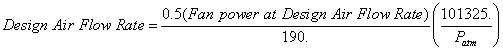
This numeric field contains the fan power in watts at the design (maximum) air flow rate through the tower. A value greater than zero must be specified or this field can be autosized. If autosized, a Plant Sizing object must be defined and the fan power is calculated as follows:
![]()
This alpha field contains the curve object name for fan power ratio (fan power/design fan power) as a function of air flow rate ratio (air flow rate/design air flow rate) [ref. Performance Curves]. The curve object must be a cubic curve and should be normalized to 1.0 at an air flow rate ratio of 1.0. If this field is left blank, a theoretical fan curve is assumed where fan power ratio is directly proportional to the air flow rate ratio cubed.
This numeric field contains the minimum air flow rate ratio. The tower fan is allowed to operate between the ratio defined here and a maximum air flow rate ratio of 1.0 (which corresponds to the design [maximum] tower air flow rate). Below this value, the tower is assumed to operate either in the “free convection” regime with the tower fan off, or the tower fan is cycled on/off to maintain the exiting water set point temperature. The minimum air flow rate ratio must be greater than or equal to 0.2 and less than or equal to 0.5, with a default value of 0.2 if the field is left blank.
This numeric field contains the fraction of tower capacity available in the free convection regime (i.e., when the tower fan is off but water continues to flow through the tower). The tower fan does not operate when the free convection tower capacity is able to meet or exceed the exiting water set point temperature. The air flow rate through the tower in the free convection regime is assumed to be this same fraction of the tower design air flow rate. The fraction of tower capacity in free convection regime must be greater than or equal to 0 and less than or equal to 0.2, with a default value of 0.125 if this field is left blank.
This numeric field contains the capacity of the tower’s electric basin heater in watts per degree Kelvin. This field is used in conjunction with the Basin Heater Setpoint Temperature described in the following field. The basin heater electric power is equal to this field multiplied by the difference between the basin heater set point temperature and the outdoor dry-bulb temperature. The basin heater only operates when the tower fan is off and water is not flowing through the tower, regardless of the basin heater schedule described below. The basin heater capacity must be greater than or equal to zero, with a default value of zero if this field is left blank.
This numeric field contains the set point temperature (˚C) for the basin heater described in the previous field. The basin heater is active when the outdoor air dry-bulb temperature falls below this setpoint temperature, as long as the tower fan is off and water is not flowing through the tower. This set point temperature must be greater than or equal to 2˚C, and the default value is 2˚C if this field is left blank.
This alpha field contains the name of the basin heater operating schedule. The basin heater operating schedule is assumed to be an on/off schedule and the heater is available to operate any time the schedule value is greater than 0. The basin heater operates when scheduled on and the outdoor air dry-bulb temperature is below the set point temperature described in the previous field. If this field is left blank, the basin heater is available to operate throughout the simulation. Regardless of this schedule, the basin heater may only operate when the cooling tower fan is off and water is not flowing through the tower.
This field is used to choose which method is used to model the amount of water evaporated by the cooling tower. There are two options: ‘LossFactor’ or ‘SaturatedExit’. The default is SaturatedExit. The user-defined loss factor is entered in the following field. By assuming that the air leaving the tower is saturated, the evaporation can be directly calculated using moist air engineering calculations with data available within the cooling tower model (and does not require additional user input).
This field is used to specify the rate of water evaporated from the cooling tower and lost to the outside air [percent/K]. This field is only used if the Evaporation Calculation Mode is set to LossFactor. The evaporation loss is then calculated as a fraction of the circulating condenser water flow and varies with the temperature change in the condenser water. The value entered here is in units of percent-per-degree Kelvin. The evaporation rate will equal this value times each degree Kelvin of temperature drop in the condenser water. Typical values are from 0.15 to 0.27 [percent/K]. The default is 0.2.
This numeric field contains the percent (%) of design water flow rate lost to the atmosphere at the design air flow rate due to drift, which is water droplets that are entrained in the airstream as it passes through the tower. Drift is assumed to vary directly with tower air flow rate ratio, and is in addition to the amount of water lost to the atmosphere due to evaporation and/or blowdown. Typical values for water usage due to drift are from 0.05 to 0.2% of the total water circulation rate with currently-available drift eliminators from tower manufacturers. The value entered in this field must be greater than or equal to zero, and the default is zero if the field is left blank.
This field specifies which method is used to determine blowdown rates. There two options ‘ConcentrationRatio’ or ‘ScheduledRate’. The choice will determine which of the two models below is used. The default is ConcentrationRatio.
This field is used to dynamically adjust the rate of blowdown in the cooling tower as a function of the rate of evaporation. Blowdown is water intentionally drained from the tower in order to offset the build up of solids in the water that would otherwise occur because of evaporation. The value entered here is dimensionless. It can be characterized as the ratio of solids in the blowdown water to solids in the make up water. Typical values for tower operation are 3 to 5. The default value is 3.
This alpha field contains the name of the schedule used to define the amount of water (m3/s) flushed from the basin on a periodic basis to purge the condenser loop of mineral scale build-up and other contaminants. The amount of water use due to blowdown depends on the makeup water quality and is specific to each geographical location. Typical values range from 0.0002 to 0.0013 m3/s (17.3 to 112.3 m3/day). This water usage is in addition to the amount of water lost to the atmosphere due to evaporation and/or drift. Since blowdown occurs when the basin water contaminant concentration is high, blowdown only occurs when the cooling tower is active and water is flowing through the tower (regardless of the water usage defined by this schedule).
This field is optional. It is used to describe where the tower obtains water used for evaporative cooling. If blank or omitted, then the tower will obtain water directly from the mains. If the name of a WaterUser:Storage object is used here, then the tower will obtain its water from that tank. If a tank is specified, the tower will attempt to obtain all the water it uses from the tank. However if the tank cannot provide all the water the tower needs, then the tower will still operate and obtain the rest of the water it needs from the mains (referred to as ‘Starved’ water).
This optional alpha field specifies the outdoor air node name used to define the conditions of the air entering the cooling tower. If this field is left blank, the outdoor air conditions entering the cooling tower are taken directly from the weather data. If this field is not blank, the node name specified must also be specified in an OutdoorAir:Node object where the height of the node is taken into consideration when calculating outdoor air conditions from the weather data. Alternately, the node name may be specified in an OutdoorAir:NodeList object where the outdoor air conditions are taken directly from the weather data.
This integer field contains the number of cells in the multi-cell cooling tower. If not entered, the program will assume it is a single-cell cooling tower
This alpha field specifies the method used to control the number of cells used to meet the load, the two choices are:
MinimalCell: the program will use minimal number of cells needed, all other cells will be shut down with no water flow. It will attempt to use as few cells as possible to cool the fluid. In no case, however, will the flow per cell be allowed to exceed its maximum value defined by the Maximum Water Flow Rate Fraction.
MaximalCel : As many cells as possible will be turned on. In no case, however, will the flow per cell be allowed to drop below its minimum value specified by the Minimum Water Flow Rate Fraction.
This numeric field specifies the allowable smallest fraction of the design water flow rate. Flows less than this value will commonly result in fluid distribution problems; the pressure at each nozzle will be too weak for the fluid to be sprayed out in the correct pattern, not all the fill would be wet. If this field is left blank, the default value is 0.33.
This numeric field specifies the allowable largest fraction of the design water flow rate. If this field is left blank, the default value is 2.5.
This optional numeric field allows the user to specify a sizing factor for this component. The sizing factor is used when the component design inputs are autosized: the autosizing calculations are performed as usual and the results are multiplied by the sizing factor. Sizing factor allows the user to size a component to meet part of the design load while continuing to use the autosizing feature.For this component the inputs that would be altered by the sizing factor are:
1. Design Water Flow Rate;
2. Design Air Flow Rate;
3. Design Fan Power.
An example IDF specification for this object is shown below:
CoolingTower:VariableSpeed,
Big Tower1, !- Tower Name
Condenser 1 Inlet Node, !- Water Inlet Node Name
Condenser 1 Outlet Node, !- Water Outlet Node Name
YorkCalc, !- Tower Model Type
, !- Tower Model Coefficient Name
25.5556, !- Design Inlet Air Wet-Bulb Temperature {C}
3.8889, !- Design Approach Temperature {C}
5.5556, !- Design Range Temperature {C}
0.0015, !- Design Water Flow Rate {m3/s}
1.6435, !- Design Air Flow Rate {m3/s}
275, !- Design Fan Power {W}
FanRatioCurve, !- Fan Power Ratio - function of Air Flow Rate Curve Name
0.2, !- Minimum Air Flow Rate Ratio
0.125, !- Fraction of Tower Capacity in Free Convection Regime
450.0, !- Basin Heater Capacity {W/K}
4.5, !- Basin Heater Set Point Temperature {C}
BasinSchedule, !- Basin Heater Operating Schedule Name
SaturatedExit, !- Evaporation Loss Mode
, !- Evaporation Loss Factor
0.05, !- Makeup Water Usage due to Drift {%}
ScheduledRate, !- Blowdown Calculation Mode
BlowDownSchedule, !- Schedule Name for Makeup Water Usage due to Blowdown
, !- Name of Water Storage Tank for Supply
, !- Outdoor Air Inlet Node Name
4, !- Number of Cells
MinimalCell, !- Cell Control
, !- Cell Minimum Water Flow Rate Fraction
, !- Cell Maximum Water Flow Rate Fraction
1.000 ; !- Sizing Factor
HVAC,Average,Tower Fan Electric Power [W]
HVAC,Sum,Tower Fan Electric Consumption [J]
Zone,Meter,Electricity:Plant [J]
Zone,Meter,HeatRejection:Electricity [J]
HVAC,Average,Tower Heat Transfer [W]
HVAC,Average,Tower Water Inlet Temp [C]
HVAC,Average,Tower Water Outlet Temp [C]
HVAC,Average,Tower Water Mass Flow Rate [kg/s]
HVAC,Average,Tower Fan Part-Load Ratio
HVAC,Average,Tower Air Flow Rate Ratio
HVAC,Average,Number of Cells Operating
A tower uses either mains water or storage tank for make-up water.
When mains water is used:
HVAC,Average,Tower Water Make Up Rate [m3/s]
HVAC,Sum,Tower Water Make Up [m3]
Zone,Meter,Water:Plant [m3]
Zone,Meter,HeatRejection:Water [m3]
HVAC,Sum,Tower Water Make Up Mains Draw [m3]
Zone,Meter,MainsWater:Plant [m3]
Zone,Meter,HeatRejection:MainsWater [m3]
When storage tank water is used:
HVAC,Average,Tower Water Make Up Rate [m3/s]
HVAC,Sum,Tower Water Make Up [m3]
HVAC,Sum,Tower Water From Storage Tank Rate [m3/s]
HVAC,Sum,Tower Water From Storage Tank [m3]
Zone,Meter,Water:Plant [m3]
Zone,Meter,HeatRejection:Water [m3]
HVAC,Sum,Tower Water Starved By Storage Tank Rate [m3/s]
HVAC,Sum,Tower Water Starved By Storage Tank [m3]
Zone,Meter,Water:Plant [m3]
Zone,Meter,HeatRejection:Water [m3]
HVAC,Sum,Tower Water Make Up Mains Draw [m3]
Zone,Meter,MainsWater:Plant [m3]
Zone,Meter,HeatRejection:MainsWater [m3]
HVAC,Average,Tower Water Evaporation Rate [m3/s]
HVAC,Sum,Tower Water Evaporation [m3]
HVAC,Average,Tower Water Drift Rate [m3/s]
HVAC,Sum,Tower Water Drift [m3]
HVAC,Average,Tower Water Blowdown Rate [m3/s]
HVAC,Sum,Tower Water Blowdown [m3]
IF specified:
HVAC,Average,Tower Basin Heater Electric Power [W]
HVAC,Sum,Tower Basin Heater Electric Consumption [J]
Zone,Meter,Electricity:Plant [J]
Zone,Meter,HeatRejection:Electricity [J]
These outputs are the electric power input to the tower fan. Consumption is metered on HeatRejection:Electricity, Electricity:Plant, and Electricity:Facility.
This is the on/off cycling rate of the tower fan when free convection cannot meet the set point temperature and the tower capacity at the minimum air flow rate ratio drives the tower exiting water temperature below the set point temperature. The fan part-load ratio is calculated as the ratio of the exiting water temperature in the free convection regime minus the exiting water temperature set point divided by the exiting water temperature in the free convection regime minus the exiting water temperature at the minimum air flow rate ratio. If tower air flow is at or above the minimum air flow rate ratio, then the tower fan part-load ratio is 1.0.
This is the rate at which heat is removed from the condenser water loop by the tower.
These outputs are the tower water inlet and outlet temperatures, and mass flow rate of the circulating condenser water loop.
This is the ratio of air flow through the tower to the design air flow rate. During times when the tower can maintain the condenser loop set point temperature using free convection (when the fan in not operating), the air flow rate ratio is assumed to be equal to the field Fraction of Tower Capacity in Free Convection Regime. During times when the fan cycles on/off to maintain the outlet water set point temperature, the air flow rate ratio is calculated as the summation of Fan Part-Load Ratio multiplied by the Minimum Air Flow Rate Ratio and (1.0 - Fan Part-Load Ratio) multiplied by the fraction of Tower Capacity in Free Convection Regime.
These outputs are the electric power input to the tower basin heater. Consumption is metered on HeatRejection:Electricity, Electricity:Plant, and Electricity:Facility.
These outputs are the water consumed by the wet cooling tower for external water sprays used to augment heat transfer. This is the total of evaporation, drift, and blowdown.
These outputs provide the breakdown of the different components of water use during cooling tower operation.
If a water storage tank is used to provide water to the tower, then the following output variables will also be available.
These are the rate and volume of water provided by the Water Storage Tank.
These are the rate and volume of water the Storage Tank connections was not able to provide. The starved water is assumed to come from the mains. The tower’s operation is not affected by a lack of storage tank water.
This represents the number of cells operating at each time step.
Variable speed cooling towers can be modeled by EnergyPlus with user-selectable performance based on the CoolTools correlation, YorkCalc correlation, or user-defined coefficients for either the CoolTools or YorkCalc correlations. The empirical CoolTools tower correlation uses a set of 35 coefficients to model the thermal performance (approach temperature) of a cooling tower based on four independent variables. If the user specifies Model Type = CoolToolsCrossFlow in the CoolingTower:VariableSpeed object, then the 35 coefficients derived for the CoolTools simulation model are used and these coefficients are already defined within EnergyPlus. If the user specifies Model Type = CoolToolsUserDefined, then the user must enter a CoolingTowerPerformance:CoolTools object to define the 35 coefficients that will be used by the CoolTools correlation.
The user must specify a name for the model coefficient object, and this name must be used in the CoolingTower:VariableSpeed object (field Model Coefficient Name) to tell the program to use these coefficients. Next, the user enters the minimum and maximum values for inlet air wet-bulb temperature, range temperature, approach temperature, and water mass flow rate ratio to specify the valid range for which the model coefficients were derived. For all of these variables, the program issues warnings if the actual values are beyond the minimum/maximum values specified. For inlet air wet-bulb temperature and water mass flow rate ratio, the values of these variables used in the calculation of approach temperature are limited to be within the valid minimum/maximum range specified. For approach and range, the warnings are issued if the values are beyond the specified minimum/maximum range but the actual values are still used.
The CoolTools correlation has four independent variables: inlet air wet-bulb temperature (Twb), tower range temperature (Tr), water flow rate ratio (FRwater), and air flow rate ratio (FRair). Temperatures are in units of ˚C and flow rate ratios are dimensionless (actual flow rate divided by design flow rate). Using these independent variables, tower approach temperature (˚C) is calculated as follows:
Approach = Coeff(1) + Coeff(2)•FRair + Coeff(3)•(FRair)2 +
Coeff(4)•(FRair)3 + Coeff(5)•FRwater +
Coeff(6)•FRair•FRwater + Coeff(7)•(FRair)2•FRwater +
Coeff(8)•(FRwater)2 + Coeff(9)•FRair•(FRwater)2 +
Coeff(10)•(FRwater)3 + Coeff(11)•Twb + Coeff(12)•FRair•Twb +
Coeff(13)•(FRair)2•Twb + Coeff(14)•FRwater•Twb +
Coeff(15)•FRair•FRwater•Twb + Coeff(16)•(FRwater)2•Twb +
Coeff(17)•(Twb)2 + Coeff(18)•FRair•(Twb)2 +
Coeff(19)•FRwater•(Twb)2 + Coeff(20)•(Twb)3 + Coeff(21)•Tr +
Coeff(22)•FRair•Tr + Coeff(23)•FRair•FRair•Tr +
Coeff(24)•FRwater•Tr + Coeff(25)•FRair•FRwater•Tr +
Coeff(26)•(FRwater)2•Tr + Coeff(27)•Twb•Tr +
Coeff(28)•FRair•Twb•Tr + Coeff(29)•FRwater•Twb•Tr +
Coeff(30)•(Twb)2•Tr + Coeff(31)•(Tr)2 + Coeff(32)•FRair•(Tr)2 +
Coeff(33)•FRwater•(Tr)2 + Coeff(34)•Twb•(Tr)2 + Coeff(35)•(Tr)3
This object allows the user to specify model coefficients for use with the CoolTools correlation shown above. It is recommended that a broad set of cooling tower performance data be used to generate these model coefficients. The data set used to create the model coefficients should cover the entire range of water and air flow rate ratios and inlet air wet-bulb, range, and approach temperatures expected during the simulation.
This alpha field contains the identifying name for the variable speed cooling tower model coefficients.
This numeric field contains the minimum inlet air wet-bulb temperature to be used by the model (approach temperature correlation). Inlet air wet-bulb temperatures less than this value will not be used; instead, the minimum inlet air wet-bulb temperature specified here will be used by the correlation and a warning will be issued.
This numeric field contains the maximum inlet air wet-bulb temperature to be used by the model (approach temperature correlation). Inlet air wet-bulb temperatures greater than this value will not be used; instead, the maximum inlet air wet-bulb temperature specified here will be used by the correlation and a warning will be issued.
This numeric field contains the minimum range temperature (inlet water temperature minus outlet water temperature) to be used by the empirical model. If the range temperature is less than this value the actual range temperature is still passed to the empirical model but a warning will be issued.
This numeric field contains the maximum range temperature (inlet water temperature minus outlet water temperature) to be used by the empirical model. If the range temperature is greater than this value the actual range temperature is still passed to the empirical model but a warning will be issued.
This numeric field contains the minimum approach temperature (outlet water temperature minus inlet air wet-bulb temperature) to be used by the empirical model. If the calculated approach temperature is less than this value then the calculated value is still used but a warning will be issued.
This numeric field contains the maximum approach temperature (outlet water temperature minus inlet air wet-bulb temperature) to be used by the empirical model. If the calculated approach temperature is greater than this value then the calculated value is still used but a warning will be issued.
This numeric field contains the minimum water flow rate ratio (ratio of actual water flow rate to rated water flow rate) to be used by the empirical model. Water flow rate ratios less than this value will not be used; instead, the minimum water flow rate ratio specified here will be used by the model and a warning will be issued.
This numeric field contains the maximum water flow rate ratio (ratio of actual water flow rate to rated water flow rate) to be used by the empirical model. Water flow rate ratios greater than this value will not be used; instead, the maximum water flow rate ratio specified here will be used by the model and a warning will be issued.
These numeric fields contain the coefficients to be used by the CoolTools approach temperature correlation shown above.
An example IDF specification for this object is shown below:
CoolingTowerPerformance:CoolTools,
CoolTools CrossFlow Default Model, !- Tower Model Coefficient Name
-1.0, !- Minimum Inlet Air Wet-Bulb Temperature {C}
26.6667, !- Maximum Inlet Air Wet-Bulb Temperature {C}
1.1111, !- Minimum Range Temperature {C}
11.1111, !- Maximum Range Temperature {C}
1.1111, !- Minimum Approach Temperature {C}
11.1111, !- Maximum Approach Temperature {C}
0.75, !- Minimum Water Flow Rate Ratio
1.25, !- Maximum Water Flow Rate Ratio
0.52049709836241, !- Coefficient 1
-10.617046395344, !- Coefficient 2
10.7292974722538, !- Coefficient 3
-2.74988377158227, !- Coefficient 4
4.73629943913743, !- Coefficient 5
-8.25759700874711, !- Coefficient 6
1.57640938114136, !- Coefficient 7
6.51119643791324, !- Coefficient 8
1.50433525206692, !- Coefficient 9
-3.2888529287801, !- Coefficient 10
0.0257786145353773, !- Coefficient 11
0.182464289315254, !- Coefficient 12
-0.0818947291400898, !- Coefficient 13
-0.215010003996285, !- Coefficient 14
0.0186741309635284, !- Coefficient 15
0.0536824177590012, !- Coefficient 16
-0.00270968955115031, !- Coefficient 17
0.00112277498589279, !- Coefficient 18
-0.00127758497497718, !- Coefficient 19
0.0000760420796601607, !- Coefficient 20
1.43600088336017, !- Coefficient 21
-0.5198695909109, !- Coefficient 22
0.117339576910507, !- Coefficient 23
1.50492810819924, !- Coefficient 24
-0.135898905926974, !- Coefficient 25
-0.152577581866506, !- Coefficient 26
-0.0533843828114562, !- Coefficient 27
0.00493294869565511, !- Coefficient 28
-0.00796260394174197, !- Coefficient 29
0.000222619828621544, !- Coefficient 30
-0.0543952001568055, !- Coefficient 31
0.00474266879161693, !- Coefficient 32
-0.0185854671815598, !- Coefficient 33
0.00115667701293848, !- Coefficient 34
0.000807370664460284; !- Coefficient 35
No additional cooling tower report variables are output when this object is used.
Variable speed cooling towers can be modeled by EnergyPlus with user-selectable performance based on the CoolTools correlation, YorkCalc correlation, or user-defined coefficients for either the CoolTools or YorkCalc correlations. The empirical YorkCalc tower correlation uses a set of 27 coefficients to model the thermal performance (approach temperature) of a variable speed cooling tower based on three independent variables. If the user specifies Tower Model Type = YorkCalc in the CoolingTower:VariableSpeed object, then the 27 coefficients derived for the YorkCalc simulation model are used and these coefficients are already defined within EnergyPlus. If the user specifies Tower Model Type = YorkCalcUserDefined, then the user must enter a CoolingTowerPerformance:YorkCalc object to define the 27 coefficients that will be used by the YorkCalc correlation.
The user must specify a name for the model coefficient object, and this name must be used in the CoolingTower:VariableSpeed object (field Model Coefficient Name) to tell the program to use these coefficients. Next, the user enters the minimum and maximum values for inlet air wet-bulb temperature, range temperature, approach temperature, and water mass flow rate ratio to specify the valid range for which the model coefficients were derived. The user also specifies the maximum valid liquid-to-gas ratio. For all of these variables, the program issues warnings if the actual values are beyond the minimum/maximum values specified. For inlet air wet-bulb temperature and water mass flow rate ratio, the values of these variables used in the calculation of approach temperature are limited to be within the valid minimum/maximum range specified. For approach, range, and liquid-to-gas ratio the warnings are issued if the values are beyond the specified minimum/maximum range but the actual values are still used.
The YorkCalc correlation has three independent variables: inlet air wet-bulb temperature (Twb), tower range temperature (Tr), and the liquid-to-gas ratio (ratio of water flow rate ratio to air flow rate ratio = LGRatio). Temperatures are in units of ˚C and liquid-to-gas ratio is dimensionless. Using these independent variables, an approach temperature (˚C) is calculated as follows:
Approach = Coeff(1) + Coeff(2)•Twb + Coeff(3)•Twb2 + Coeff(4)•Tr +
Coeff(5)•Twb•Tr + Coeff(6)•Twb2•Tr + Coeff(7)•Tr2 +
Coeff(8)•Twb•Tr2 + Coeff(9)•Twb2•Tr2 + Coeff(10)•LGRatio +
Coeff(11)•Twb•LGRatio + Coeff(12)•Twb2•LGRatio +
Coeff(13)•Tr•LGRatio + Coeff(14)•Twb•Tr•LGRatio +
Coeff(15)•Twb2•Tr•LGRatio + Coeff(16)•Tr2•LGRatio +
Coeff(17)•Twb•Tr2•LGRatio + Coeff(18)•Twb2•Tr2•LGRatio +
Coeff(19)•LGRatio2 + Coeff(20)•Twb•LGRatio2 +
Coeff(21)• Twb2•LGRatio2 + Coeff(22)•Tr•LGRatio2 +
Coeff(23)•Twb•Tr•LGRatio2 + Coeff(24)•Twb2•Tr•LGRatio2 +
Coeff(25)•Tr2•LGRatio2 + Coeff(26)•Twb•Tr2•LGRatio2 +
Coeff(27)•Twb2•Tr2•LGRatio2
This object allows the user to specify model coefficients for use with the YorkCalc correlation shown above. It is recommended that a broad set of cooling tower performance data be used to generate these model coefficients. The data set used to create the model coefficients should cover the entire range of water and air flow rate ratios and inlet air wet-bulb, range, and approach temperatures expected during the simulation.
This alpha field contains the identifying name for the variable speed cooling tower model coefficients.
This numeric field contains the minimum inlet air wet-bulb temperature to be used by the model (approach temperature correlation). Inlet air wet-bulb temperatures less than this value will not be used; instead, the minimum inlet air wet-bulb temperature specified here will be used by the correlation and a warning will be issued.
This numeric field contains the maximum inlet air wet-bulb temperature to be used by the model (approach temperature correlation). Inlet air wet-bulb temperatures greater than this value will not be used; instead, the maximum inlet air wet-bulb temperature specified here will be used by the model and a warning will be issued.
This numeric field contains the minimum range temperature (inlet water temperature minus outlet water temperature) to be used by the empirical model. If the range temperature is less than this value the actual range temperature is still passed to the empirical model but a warning will be issued.
This numeric field contains the maximum range temperature (inlet water temperature minus outlet water temperature) to be used by the empirical model. If the range temperature is greater than this value the actual range temperature is still passed to the empirical model but a warning will be issued.
This numeric field contains the minimum approach temperature (outlet water temperature minus inlet air wet-bulb temperature) to be used by the empirical model. If the calculated approach temperature is less than this value then the calculated value is still used but a warning will be issued.
This numeric field contains the maximum approach temperature (outlet water temperature minus inlet air wet-bulb temperature) to be used by the empirical model. If the calculated approach temperature is greater than this value then the calculated value is still used but a warning will be issued.
This numeric field contains the minimum water flow rate ratio (ratio of actual water flow rate to rated water flow rate) to be used by the empirical model. Water flow rate ratios less than this value will not be used; instead, the minimum water flow rate ratio specified here will be used by the model and a warning will be issued.
This numeric field contains the maximum water flow rate ratio (ratio of actual water flow rate to rated water flow rate) to be used by the empirical model. Water flow rate ratios greater than this value will not be used; instead, the maximum water flow rate ratio specified here will be used by the model and a warning will be issued.
This numeric field contains the maximum liquid-to-gas ratio (ratio of actual water flow rate ratio [capped to be within the minimum/maximum water flow rate ratio defined above as necessary] to actual air flow rate ratio) to be used by the empirical model. If the liquid-to-gas ratio is greater than this value the actual liquid to gas ratio is still passed to the empirical model but a warning will be issued.
These numeric fields contain the coefficients to be used by the YorkCalc approach temperature correlation shown above.
An example IDF specification for this object is shown below:
CoolingTowerPerformance:YorkCalc
YorkCalc Default Tower Model, !- Tower Model Coefficient Name
-34.4, !- Minimum Inlet Air Wet-Bulb Temperature {C}
26.6667, !- Maximum Inlet Air Wet-Bulb Temperature {C}
1.1111, !- Minimum Range Temperature {C}
22.2222, !- Maximum Range Temperature {C}
1.1111, !- Minimum Approach Temperature {C}
40.0, !- Maximum Approach Temperature {C}
0.75, !- Minimum Water Flow Rate Ratio
1.25, !- Maximum Water Flow Rate Ratio
8.0, !- Maximum Liquid to Gas Ratio
-0.359741205, !- Coefficient 1
-0.055053608, !- Coefficient 2
0.0023850432, !- Coefficient 3
0.173926877, !- Coefficient 4
-0.0248473764, !- Coefficient 5
0.00048430224, !- Coefficient 6
-0.005589849456, !- Coefficient 7
0.0005770079712, !- Coefficient 8
-0.00001342427256, !- Coefficient 9
2.84765801111111, !- Coefficient 10
-0.121765149, !- Coefficient 11
0.0014599242, !- Coefficient 12
1.680428651, !- Coefficient 13
-0.0166920786, !- Coefficient 14
-0.0007190532, !- Coefficient 15
-0.025485194448, !- Coefficient 16
0.0000487491696, !- Coefficient 17
0.00002719234152, !- Coefficient 18
-0.0653766255555556, !- Coefficient 19
-0.002278167, !- Coefficient 20
0.0002500254, !- Coefficient 21
-0.0910565458, !- Coefficient 22
0.00318176316, !- Coefficient 23
0.000038621772, !- Coefficient 24
-0.0034285382352, !- Coefficient 25
0.00000856589904, !- Coefficient 26
-0.000001516821552; !- Coefficient 27
No additional cooling tower report variables are output when this object is used.
Evaporative fluid coolers are components that may be assigned to condenser loops. The Evaporative fluid cooler is modeled as a counter flow heat exchanger with single-speed fans (induced draft configuration). The user must define fluid cooler performance via one of three methods: design heat transfer coefficient-area product (UA) and design water flow rate, or standard fluid cooler design capacity at a specific rating point or design capacity at non standard conditions. Regardless of which method is chosen, the design airflow rate and corresponding fan power must be specified.
The evaporative fluid cooler seeks to maintain the temperature of the water exiting the evaporative fluid cooler at (or below) a set point. The set point schedule value is defined by the field “Condenser Loop Temperature Setpoint Node Name or Reference” for the CondenserLoop object. The model first checks to see whether inlet water temperature is at or below the set point. If so, then the fluid cooler fan is not turned on and all the flow goes through bypass. If the inlet water temperature is above the set point then the fluid cooler fan is turned on to reduce the exiting water temperature to the set point. If the capacity control is FanCycling, the model assumes that part-load operation is represented by a simple linear interpolation between two steady-state regimes (i.e., fluid cooler fan on for the entire simulation timestep and fluid cooler fan off for the entire simulation timestep). Cyclic losses are not taken into account. If the capacity control is FluidBypass, the model determines the fraction of water flow to be bypassed while the remaining water goes through the fluid cooler cooling media and gets cooled, then the two water flows mix to meet the setpoint temperature. In this case, the fan runs at full speed for the entire timestep.
Evaporative fluid coolers consume water through evaporation, drift, and blowdown. The model can be used to predict water consumed by the fluid coolers. For this purpose, the last seven input fields can either be provided in the input or if nothing is specified then the default values for these fields will be used. These fields provide the methods of controlling details of the water consumption calculations. The user can specify connections to the rest of the building’s water system by providing the name of a water storage tanks (i.e. WaterUse:Storage objects). The schematic of the system is shown below:
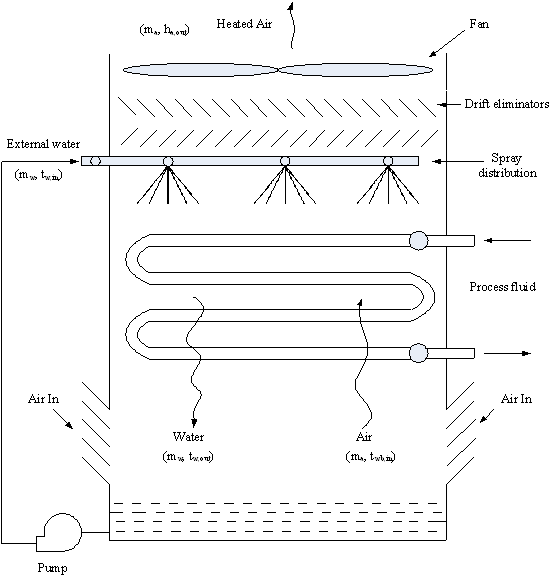
Figure 67. Schematic diagram for evaporative fluid cooler
Where,
h = Enthalpy (j/kg-K)
m = mass flow rate (kg/s)
Subscripts
a = air
w = water
wb = wet-bulb
in = inlet
out= outlet
This alpha field contains the identifying name for the fluid cooler.
This alpha field contains the identifying name for the fluid cooler’s water inlet node.
This alpha field contains the identifying name for the fluid cooler’s water outlet node.
This numeric field contains the design air flow rate induced by the fluid cooler fan in m3/s. The field must contain a value greater than zero regardless of the fluid cooler performance input method. Alternately, this field can be autosized. See Engineering Reference document for autosizing calculations.
This numeric field contains the fan power (in watts) at the design air flow rate specified in the previous field. The field must contain a value greater than zero regardless of the fluid cooler performance input method. Alternately, this field can be autosized. See Engineering Reference document for autosizing calculations.
This numeric field contains the design spray water flow rate through the fluid cooler in m3/s. A value greater than zero must be specified regardless of the performance input method,
This alpha field contains the method by which the user will specify fluid cooler performance: “UFactorTimesAreaAndDesignWaterFlowRate” or “StandardDesignCapacity” or “UserSpecifiedDesignCapacity”.
This optional alpha field specifies the outdoor air node name used to define the conditions of the air entering the fluid cooler. If this field is left blank, the outdoor air conditions entering the fluid cooler are taken directly from the weather data. If this field is not blank, the node name specified must also be specified in an OutdoorAir:Node object where the height of the node is taken into consideration when calculating outdoor air conditions from the weather data. Alternately, the node name may be specified in an OutdoorAir:NodeList object where the outdoor air conditions are taken directly from the weather data.
This numeric input field contains the heat rejection capacity of the fluid cooler in watts, with entering water at 35C (95F), leaving water at 29.4C (85F), entering air at 25.6C (78F) wetbulb and 35C (95F) drybulb temperatures. The design water flow rate is assumed to be 5.382E-8 m3/s per watt of nominal capacity (3 gpm/ton). 125% of this capacity gives the actual fluid cooler heat rejection at these operating conditions (based on historical assumption that the evaporative fluid cooler must dissipate 0.25W of compressor heat for every watt of heat removed by the evaporator). This field is only used for performance input method =”StandardDesignCapacity”. For other input methods this field is ignored. The standard conditions mentioned above for “standard design capacity” are already specified in the EnergyPlus. So the input fields such as design entering water temp., design entering air wet-bulb and dry-bulb temp. and design water flow rate, if provided in the input, will be ignored for the StandardDesignCapacity performance input method. Also, the standard conditions are for water as a fluid type so this performance input method can only be used with water as a fluid type (ref. CondenserLoop object).
This numeric field contains the heat transfer coefficient-area product (UA) in watts per degree Celsius corresponding to the design air and water flow rates specified above. If the input field “Performance Input Method” is specified as “UFactorTimesAreaAndDesignWaterFlowRate”, then a UA value greater than zero but less than or equal to 300,000 must be defined, or the field can be autosized. If autosized, a Plant Sizing object must be defined and the design fluid cooler UA value is derived from the design load to be rejected by the condenser loop and the design loop delta T (Ref. Sizing and Input for Design Calculations and Component Autosizing), the fluid cooler inlet air dry-bulb and wetbulb temperature are taken from the input. This field is only used for performance input method =” UFactorTimesAreaAndDesignWaterFlowRate”. For other performance input methods, this field is ignored.
This numeric field contains the design water flow rate through the fluid cooler in m3/s. This value is the flow rate of the condenser loop water being cooled by the fluid cooler. This field is ignored for the “StandardDesignCapacity” performance input method. If autosized, a Plant Sizing object must be defined and the design water flow rate is derived from the design load to be rejected by the condenser loop and the design loop delta T (Ref. Sizing and Input for Design Calculations and Component Autosizing).
This numeric input field contains the heat rejection capacity of the fluid cooler in watts. Design conditions for this capacity i.e. entering air dry-bulb temperature, entering air wet-bulb temperature and entering water temperature must be provided in the input. Only used for Performance Input Method = UserSpecifiedDesignCapacity; for other performance input methods this field is ignored.
This numeric field contains entering water temperature at nominal conditions in degrees Celsius. The design entering water temperature must be greater than the design entering air temperature. Only used for Performance Input Method = UserSpecifiedDesignCapacity; for other performance input methods this field is ignored.
This numeric field contains entering air dry-bulb temperature at nominal conditions in degrees Celsius. The design entering air temperature must be greater than the design entering air wet-bulb temperature. Only used for Performance Input Method = UserSpecifiedDesignCapacity; for other performance input methods this field is ignored.
This numeric field contains entering air wetbulb temperature at nominal conditions in degrees Celsius. The design entering air wet-bulb temperature must be less than the design entering air (dry-bulb) temperature. Only used for Performance Input Method = UserSpecifiedDesignCapacity; for other performance input methods this field is ignored.
This alpha field contains the cooling capacity control for the evaporative fluid cooler. Two choices are available: FanCycling and FluidBypass. During part-load conditions, there are two ways to maintain the exiting water temperature at the setpoint: either cycling the evaporative fluid cooler fan, or bypassing portion of the evaporative fluid cooler water with a three-way valve. For FluidBypass, the evaporative fluid cooler fan still runs at full speed for the entire timestep, but only portion of the water flow goes through the evaporative fluid cooler media to get cooled while the remaining portion of the water flow gets bypassed. Two water flows then mix at the common water sump to meet the setpoint temperature.
This optional numeric field allows the user to specify a sizing factor for this component. The sizing factor is used when the component design inputs are autosized: the autosizing calculations are performed as usual and the results are multiplied by the sizing factor. Sizing factor allows the user to size a component to meet part of the design load while continuing to use the autosizing feature. For this component the inputs that would be altered by the sizing factor are:
1. Design Water Flow Rate;
2. Design Air Flow Rate;
3. Fan Power at Design Air Flow Rate;
4. U-Factor Times Area Value at Design Air Flow Rate;
Note that the U-Factor Times Area Value at Design Air Flow Rate is not multiplied by the Sizing Factor. Instead the design evaporative fluid cooler load is multiplied by the sizing factor and the design UA then calculated as usual.
This field is used to choose which method is used to model the amount of water evaporated by the evaporative fluid cooler. There are two options: LossFactor or SaturatedExit. The default is SaturatedExit. The user-defined loss factor is entered in the following field. By assuming that the air leaving the evaporative fluid cooler is saturated, the evaporation can be directly calculated using moist air engineering calculations with data available within the evaporative fluid cooler model (and does not require additional user input).
This field is used to specify the rate of water evaporated from the evaporative fluid cooler and lost to the outside air [percent/K]. This field is only used if the Evaporation Calculation Mode is set to LossFactor. The evaporation loss is then calculated as a fraction of the circulating condenser water flow and varies with the temperature change in the condenser water. The value entered here is in units of percent-per-kelvin. The evaporation rate will equal this value times each degree Kelvin of temperature drop in the condenser water. Empirical correlation is used to calculate default loss factor if it not explicitly specified in the input file.
This field is used to specify the rate of water lost to the exiting air as entrained droplets [%]. The drift loss is a percent of the condenser water flow. Default value is under investigation for now cooling tower’s evaporation loss factor is taken as default value.
This field specifies which method is used to determine blowdown rates. There two options ConcentrationRatio or ScheduledRate. The choice will determine which of the two models below is used. The default is ConcentrationRatio.
This field is used to dynamically adjust the rate of blowdown in the evaporative fluid cooler as a function of the rate of evaporation. Blowdown is water intentionally drained from the evaporative fluid cooler in order to offset the build up of solids in the water that would otherwise occur because of evaporation. The value entered here is dimensionless. It can be characterized as the ratio of solids in the blowdown water to solids in the make up water. Default value is under investigation for now cooling tower’s evaporation loss factor is taken as default value.
This alpha field contains the name of the schedule used to define the amount of water (m3/s) flushed from the basin on a periodic basis to purge the evaporative fluid cooler of mineral scale build-up and other contaminants. This schedule is only used if the Blowdown Calculation Mode is set to ScheduledRate. The amount of water use due to blowdown depends on the makeup water quality and is specific to each geographical location. Default value is under investigation for now cooling tower’s evaporation loss factor is taken as default value.This water usage is in addition to the amount of water lost to the atmosphere due to evaporation and/or drift. Since blowdown occurs when the basin water contaminant concentration is high, blowdown only occurs when the evaporative fluid cooler is active and water is flowing through the evaporative fluid cooler (regardless of the water usage defined by this schedule).
This field is optional. It is used to describe where the evaporative fluid cooler obtains water used for evaporative cooling. If blank or omitted, then the evaporative fluid cooler will obtain water directly from the mains. If the name of a WaterUse:Storage object is used here, then the evaporative fluid cooler will obtain its water from that tank. If a tank is specified, the evaporative fluid cooler will attempt to obtain all the water it uses from the tank. However if the tank cannot provide all the water the evaporative fluid cooler needs, then the evaporative fluid cooler will still operate and obtain the rest of the water it needs from the mains (referred to as ‘Starved’ water).
An IDF specification for this object is shown below:
EvaporativeFluidCooler:SingleSpeed,
Big EvaporativeFluidCooler, !- Name
Condenser EvaporativeFluidcooler Inlet Node, !- Water Inlet Node Name
Condenser EvaporativeFluidcooler Outlet Node, !- Water Outlet Node Name
3.02, !- Design Air Flow Rate {m3/s}
2250, !- Fan Power at Design Air Flow Rate {W}
0.002208, !- Design Spray Water Flow Rate {m3/s}
UserSpecifiedDesignCapacity, !- Performance Input Method
, !- Outdoor Air Inlet Node Name
, !- Standard Design Capacity {W}
, !- U-factor Times Area Value at Design Air Flow Rate {W/K}
0.001703, !- Design Water Flow Rate {m3/s}
87921, !- User Specified Design Capacity {W}
46.11, !- Design Entering Water Temperature {C}
35, !- Design Entering Air Temperature {C}
25.6; !- Design Entering Air Wet-bulb Temperature {C}
HVAC,Average,Evaporative Fluid Cooler Fan Electric Power [W]
HVAC,Sum,Evaporative Fluid Cooler Fan Electric Consumption [J]
HVAC,Average,Evaporative Fluid Cooler Heat Transfer [W]
HVAC,Average,Evaporative Fluid Cooler Water Inlet Temp [C]
HVAC,Average,Evaporative Fluid Cooler Water Outlet Temp [C]
HVAC,Average,Evaporative Fluid Cooler Water Mass Flow Rate [kg/s]
HVAC,Average,Evaporative Fluid Cooler Fluid Bypass Fraction [-]
HVAC,Average,Evaporative Fluid Cooler Water Make Up Rate [m3/s]
HVAC,Sum,Evaporative Fluid Cooler Water Make Up [m3]
HVAC,Average,Evaporative Fluid Cooler Water Evaporation Rate [m3/s]
HVAC,Sum,Evaporative Fluid Cooler Water Evaporation [m3]
HVAC,Average,Evaporative Fluid Cooler Water Drift Rate [m3/s]
HVAC,Sum,Evaporative Fluid Cooler Water Drift [m3]
HVAC,Average,Evaporative Fluid Cooler Water Blowdown Rate [m3/s]
HVAC,Sum,Evaporative Fluid Cooler Water Blowdown [m3]
HVAC,Sum,Evaporative Fluid Cooler Water Make Up Mains Draw [m3]
If Supply Water Storage Tank Name is specified:
HVAC,Average,Evaporative Fluid Cooler Water From Storage Tank Rate [m3/s]
HVAC,Sum,Evaporative Fluid Cooler Water From Storage Tank [m3]
HVAC,Average,Evaporative Fluid Cooler Water Starved by Storage Tank Rate [m3/s]
HVAC,Sum,Evaporative Fluid Cooler Water Starved by Storage Tank [m3]
The average electric power consumption of the fluid cooler fan in Watts for the timestep being reported.
Fan energy use in Joules. Consumption is metered on HeatRejection:Electricity, Electricity:Plant, and Electricity:Facility.
This is the average rate, in Watts, at which heat is removed from the condenser water loop by the fluid cooler for the time step being reported.
The fluid temperature at the fluid cooler inlet in degrees Celsius.
The fluid temperature at the fluid cooler outlet in degrees Celsius.
The average fluid mass flow rate through the fluid cooler in kg/s for the time step being reported.
This output is the average fluid bypass fraction for the time step being reported. See Capacity Control input field.
These outputs are the external spray water consumed by the evaporative fluid cooler. This is the total of evaporation, drift, and blowdown.
These outputs provide the breakdown of the different components of water use during fluid cooler operation.
The volume of make up water provided by the mains in cubic meters. If no Supply Water Storage Tank is specified, then all fluid cooler make up water is provided by the mains (same as Evaporative Fluid Cooler Water Make Up). If a Supply Water Storage Tank is specified, then the make up from the mains only occurs when sufficient water supply is not available from the tank (same as Evaporative Fluid Cooler Water Starved by Storage Tank). This output variable is metered on HeatRejection:MainsWater, MainsWater:Plant and MainsWater:Facility.
These are the rate and volume of water provided by the Supply Water Storage Tank.
These are the rate and volume of water the Supply Water Storage Tank was not able to provide. The starved water is assumed to come from the mains. The fluid cooler’s operation is not affected by a lack of storage tank water.
The two-speed evaporative fluid cooler is modeled in a similar fashion to the single-speed evaporative fluid cooler. The evaporative fluid cooler is modeled as a counter flow heat exchanger with two-speed fan (induced draft configuration. See schematic diagram in EvaporativeFluidCooler:SingleSpeed section). The user must define fluid cooler performance via one of the three methods: design heat transfer coefficient-area product (UA) and design water flow rate, or standard fluid cooler design capacity at a specific rating point or design capacity at non standard conditions. Regardless of which method is chosen, the design airflow rate and corresponding fan power must be specified.
The evaporative fluid cooler seeks to maintain the temperature of the water exiting the evaporative fluid cooler at (or below) a set point. The set point schedule value is defined by the field “Condenser Loop Temperature Setpoint Node Name or Reference” for the CondenserLoop object. The model first checks to see whether inlet water temperature is at or below the set point. If so, then the fluid cooler fan is not turned on and all the flow goes through bypass. If the inlet water temperature is above the set point then the fluid cooler fan is turned on at low speed to reduce the exiting water temperature to the set point. If operating the fluid cooler fan at low speed does not reduce the exiting water temperature to the set point, then the fluid cooler fan is increased to its high speed.
The model assumes that part-load operation is represented by a simple linear interpolation between two steady-state regimes (i.e., fluid cooler fan at high speed for the entire simulation timestep and fluid cooler fan at low speed for the entire simulation timestep, or fluid cooler fan at low speed for the entire simulation timestep and fluid cooler fan off for the entire simulation timestep). Cyclic losses are not taken into account.
Evaporative fluid coolers consume water through evaporation, drift, and blowdown. The model can be used to predict water consumed by the evaporative fluid coolers. For this purpose, the last seven input fields can either be provided in the input or if nothing is specified then the default values for these fields will be used. These fields provide methods of controlling details of the water consumption calculations. The user can specify connections to the rest of the buildings water system by providing the name of a water storage tanks (i.e. WaterUse:Storage objects).
This alpha field contains the identifying name for the fluid cooler.
This alpha field contains the identifying name for the fluid cooler’s water inlet node.
This alpha field contains the identifying name for the fluid cooler’s water outlet node.
This numeric field contains the fluid cooler air flow rate at high fan speed in m3/s. A value greater than zero must be defined regardless of fluid cooler performance input method. Alternately, this field can be autosized. See Engineering Reference document for fluid cooler autosizing.
This numeric field contains the fan power (in Watts) at the high-speed air flow rate specified in the previous field. A value greater than zero must be specified regardless of fluid cooler performance input method, or this field can be autosized. See Engineering Reference document for fluid cooler autosizing.
This numeric field contains the fluid cooler air flow rate at low fan speed in m3/s. This value must be greater than zero, less than the value specified for the field “Air Flow Rate at High Fan Speed”. This field may be autosized, in which case it is set to 50% of the “Air Flow Rate at High Fan Speed”.
This numeric field contains the fan power (in Watts) at the low-speed air flow rate specified in the previous field. This value must be specified greater than zero or the field may be autosized, in which case it is set to 16% of the “Fan Power at High Fan Speed”.
This numeric field contains the design spray water flow rate through the fluid cooler in m3/s. This input field must be specified for all the performance input methods.
This alpha field contains the method by which the user will specify fluid cooler performance: “UFactorTimesAreaAndDesignWaterFlowRate” or “StandardDesignCapacity” or “UserSpecifiedDesignCapacity”.
This optional alpha field specifies the outdoor air node name used to define the conditions of the air entering the fluid cooler. If this field is left blank, the outdoor air conditions entering the fluid cooler are taken directly from the weather data. If this field is not blank, the node name specified must also be specified in an OutdoorAir:Node object where the height of the node is taken into consideration when calculating outdoor air conditions from the weather data. Alternately, the node name may be specified in an OutdoorAir:NodeList object where the outdoor air conditions are taken directly from the weather data.
This numeric input field contains the heat rejection capacity of the fluid cooler in watts, with entering water at 35C (95F), leaving water at 29.4C (85F), entering air at 25.6C (78F) wetbulb and 35C (95F) drybulb temperatures. The design water flow rate is assumed to be 5.382E-8 m3/s per watt of nominal capacity (3 gpm/ton). 125% of this capacity gives the actual fluid cooler heat rejection at these operating conditions (based on historical assumption that the evaporative fluid cooler must dissipate 0.25W of compressor heat for every watt of heat removed by the evaporator). This field is only used for performance input method =”StandardDesignCapacity”. For other input methods this field is ignored. The standard conditions mentioned above for “standard design capacity” are already specified in the EnergyPlus. So the input fields such as design entering water temp., design entering air wet-bulb and dry-bulb temp. and design water flow rate, if provided in the input, will be ignored for the StandardDesignCapacity performance input method. Also, the standard conditions are for water as a fluid type so this performance input method can only be used with water as a fluid type (ref. CondenserLoop object).
This numeric input field contains the heat rejection capacity of the fluid cooler in watts, with entering water at 35C (95F), leaving water at 29.4C (85F), entering air at 25.6C (78F) wetbulb and 35C (95F) drybulb temperatures. The design water flow rate is assumed to be 5.382E-8 m3/s per watt of nominal capacity (3 gpm/ton). 125% of this capacity gives the actual fluid cooler heat rejection at these operating conditions (based on historical assumption that the evaporative fluid cooler must dissipate 0.25W of compressor heat for every watt of heat removed by the evaporator). This field is only used for performance input method =”StandardDesignCapacity”. For other input methods this field is ignored. The standard conditions mentioned above for “standard design capacity” are already specified in the EnergyPlus. So the input fields such as design entering water temp., design entering air wet-bulb and dry-bulb temp. and design water flow rate, if provided in the input, will be ignored for the StandardDesignCapacity performance input method. Also, the standard conditions are for water as a fluid type so this performance input method can only be used with water as a fluid type (ref. CondenserLoop object). The value specified for this field must be greater than zero but less than the value specified for the field “High-Speed Standard Design Capacity”.
This numeric field contains the heat transfer coefficient-area product (UA) in watts per degree Celsius corresponding to the high speed design air and water flow rates specified above. If the input field “Performance Input Method” is specified as “UFactorTimesAreaAndDesignWaterFlowRate”, then a UA value greater than zero but less than or equal to 2,100,000 must be defined, or the field can be autosized. If autosized, a Plant Sizing object must be defined and the design fluid cooler UA value is derived from the design load to be rejected by the condenser loop and the design loop delta T (Ref. Sizing and Input for Design Calculations and Component Autosizing), the fluid cooler inlet air dry-bulb and wetbulb temperature are taken from the input. This field is only used for performance input method =” UFactorTimesAreaAndDesignWaterFlowRate”. For other input methods this field is ignored.
This numeric field contains the heat transfer coefficient-area product (UA) in watts per degree Celsius corresponding to the low speed design air and water flow rates specified above. If the input field “Performance Input Method” is specified as “UFactorTimesAreaAndDesignWaterFlowRate”, then a UA value greater than zero but less than or equal to 300,000 and less than the value specified for the field “U-Factor Times Area Value at High Fan Speed” must be defined. This field may be autosized, in which case it is set to 60% of the “U-Factor Times Area Value at High Fan Speed”. This field is only used for performance input method =” UFactorTimesAreaAndDesignWaterFlowRate”. For other input methods this field is ignored.
This numeric field contains the design water flow rate through the fluid cooler in m3/s. This value is the flow rate of the condenser loop water being cooled by the fluid cooler. This field is ignored for the “StandardDesignCapacity” performance input method. If autosized, a Plant Sizing object must be defined and the design water flow rate is derived from the design load to be rejected by the condenser loop and the design loop delta T (Ref. Sizing and Input for Design Calculations and Component Autosizing).
This numeric input field contains the heat rejection capacity of the fluid cooler in watts. Design conditions for this capacity i.e. entering air dry-bulb temperature, entering air wet-bulb temperature and entering water temperature must be provided in the input. Only used for Performance Input Method = UserSpecifiedDesignCapacity; for other performance input methods this field is ignored.
This numeric input field contains the heat rejection capacity of the fluid cooler in watts. Design conditions for this capacity i.e. entering air dry-bulb temperature, entering air wet-bulb temperature and entering water temperature must be provided in the input. Only used for Performance Input Method = UserSpecifiedDesignCapacity; for other performance input methods this field is ignored.
This numeric field contains entering water temperature at nominal conditions in degrees Celsius. The design entering water temperature must be greater than the design entering air temperature. Only used for Performance Input Method = UserSpecifiedDesignCapacity; for other performance input methods this field is ignored.
This numeric field contains entering air dry-bulb temperature at nominal conditions in degrees Celsius. The design entering air temperature must be greater than the design entering air wet-bulb temperature. Only used for Performance Input Method = UserSpecifiedDesignCapacity; for other performance input methods this field is ignored.
This numeric field contains entering air wetbulb temperature at nominal conditions in degrees Celsius. The design entering air wet-bulb temperature must be less than the design entering air (dry-bulb) temperature. Only used for Performance Input Method = UserSpecifiedDesignCapacity; for other performance input methods this field is ignored.
This optional numeric field allows the user to specify a sizing factor for this component. The sizing factor is used when the component design inputs are autosized: the autosizing calculations are performed as usual and the results are multiplied by the sizing factor. Sizing factor allows the user to size a component to meet part of the design load while continuing to use the autosizing feature. For this component the inputs that would be altered by the sizing factor are:
1. Design Water Flow Rate;
2. Air Flow Rate at High Fan Speed;
3. Fan Power at High Fan Speed;
4. U-Factor Times Area Value at High Fan Speed;
5. Air Flow Rate at Low Fan Speed;
6. Fan Power at Low Fan Speed;
7. U-Factor Times Area Value at Low Fan Speed;
Note that the U-Factor Times Area Value at High Fan Speed is not multiplied by the Sizing Factor. Instead the design evaporative fluid cooler load is multiplied by the sizing factor and the design UA then calculated as usual. The U-Factor Times Area Value at Low Fan Speed is set to 60% of the full load design UA.
This field is used to choose which method is used to model the amount of water evaporated by the evaporative fluid cooler. There are two options: LossFactor or SaturatedExit. The default is SaturatedExit. The user-defined loss factor is entered in the following field. By assuming that the air leaving the evaporative fluid cooler is saturated, the evaporation can be directly calculated using moist air engineering calculations with data available within the evaporative fluid cooler model (and does not require additional user input).
This field is used to specify the rate of water evaporated from the evaporative fluid cooler and lost to the outside air [percent/K]. This field is only used if the Evaporation Calculation Mode is set to LossFactor. The evaporation loss is then calculated as a fraction of the circulating condenser water flow and varies with the temperature change in the condenser water. The value entered here is in units of percent-per-kelvin. The evaporation rate will equal this value times each degree Kelvin of temperature drop in the condenser water. Empirical correlation is used to calculate default loss factor if it not explicitly specified in the input file.
This field is used to specify the rate of water lost to the exiting air as entrained droplets [%]. The drift loss is a percent of the condenser water flow. Default value is under investigation for now cooling tower’s evaporation loss factor is taken as default value.
This field specifies which method is used to determine blowdown rates. There two options ConcentrationRatio or ScheduledRate. The choice will determine which of the two models below is used. The default is ConcentrationRatio.
This field is used to dynamically adjust the rate of blowdown in the evaporative fluid cooler as a function of the rate of evaporation. Blowdown is water intentionally drained from the evaporative fluid cooler in order to offset the build up of solids in the water that would otherwise occur because of evaporation. The value entered here is dimensionless. It can be characterized as the ratio of solids in the blowdown water to solids in the make up water. Default value is under investigation for now cooling tower’s evaporation loss factor is taken as default value.
This alpha field contains the name of the schedule used to define the amount of water (m3/s) flushed from the basin on a periodic basis to purge the evaporative fluid cooler of mineral scale build-up and other contaminants. This schedule is only used if the Blowdown Calculation Mode is set to ScheduledRate. The amount of water use due to blowdown depends on the makeup water quality and is specific to each geographical location. Default value is under investigation for now cooling tower’s evaporation loss factor is taken as default value.This water usage is in addition to the amount of water lost to the atmosphere due to evaporation and/or drift. Since blowdown occurs when the basin water contaminant concentration is high, blowdown only occurs when the evaporative fluid cooler is active and water is flowing through the evaporative fluid cooler (regardless of the water usage defined by this schedule).
This field is optional. It is used to describe where the evaporative fluid cooler obtains water used for evaporative cooling. If blank or omitted, then the evaporative fluid cooler will obtain water directly from the mains. If the name of a WaterUse:Storage object is used here, then the evaporative fluid cooler will obtain its water from that tank. If a tank is specified, the evaporative fluid cooler will attempt to obtain all the water it uses from the tank. However if the tank cannot provide all the water the evaporative fluid cooler needs, then the evaporative fluid cooler will still operate and obtain the rest of the water it needs from the mains (referred to as ‘Starved’ water).
Examples of an IDF specification for this object are shown below:
EvaporativeFluidCooler:TwoSpeed,
Big EvaporativeFluidCooler, !- Name
Condenser EvaporativeFluidcooler Inlet Node, !- Water Inlet Node Name
Condenser EvaporativeFluidcooler Outlet Node, !- Water Outlet Node Name
9.911, !- Air Flow Rate at High Fan Speed {m3/s}
autosize, !- Fan Power at High Fan Speed {W}
4.911, !- Air Flow Rate at Low Fan Speed {m3/s}
autosize, !- Fan Power at Low Fan Speed {W}
0.002208, !- Design Spray Water Flow Rate {m3/s}
UserSpecifiedDesignCapacity, !- Performance Input Method
, !- Outdoor Air Inlet Node Name
, !- High-Speed Standard Design Capacity {W}
, !- Low-Speed Standard Design Capacity {W}
, !- U-factor Times Area Value at High Fan Speed {W/K}
, !- U-factor Times Area Value at Low Fan Speed {W/K}
0.001703, !- Design Water Flow Rate {m3/s}
87921, !- High-Speed User Specified Design Capacity {W}
47921, !- Low-Speed User Specified Design Capacity {W}
46.11, !- Design Entering Water Temperature {C}
35, !- Design Entering Air Temperature {C}
25.6; !- Design Entering Air Wet-bulb Temperature {C}
HVAC,Average,Evaporative Fluid Cooler Fan Electric Power [W]
HVAC,Sum,Evaporative Fluid Cooler Fan Electric Consumption [J]
HVAC,Average,Evaporative Fluid Cooler Heat Transfer [W]
HVAC,Average,Evaporative Fluid Cooler Water Inlet Temp [C]
HVAC,Average,Evaporative Fluid Cooler Water Outlet Temp [C]
HVAC,Average,Evaporative Fluid Cooler Water Mass Flow Rate [kg/s]
HVAC,Average,Evaporative Fluid Cooler Water Make Up Rate [m3/s]
HVAC,Sum,Evaporative Fluid Cooler Water Make Up [m3]
HVAC,Average,Evaporative Fluid Cooler Water Evaporation Rate [m3/s]
HVAC,Sum,Evaporative Fluid Cooler Water Evaporation [m3]
HVAC,Average,Evaporative Fluid Cooler Water Drift Rate [m3/s]
HVAC,Sum,Evaporative Fluid Cooler Water Drift [m3]
HVAC,Average,Evaporative Fluid Cooler Water Blowdown Rate [m3/s]
HVAC,Sum,Evaporative Fluid Cooler Water Blowdown [m3]
HVAC,Sum,Evaporative Fluid Cooler Water Make Up Mains Draw [m3]
If Supply Water Storage Tank Name is specified:
HVAC,Average,Evaporative Fluid Cooler Water From Storage Tank Rate [m3/s]
HVAC,Sum,Evaporative Fluid Cooler Water From Storage Tank [m3]
HVAC,Average,Evaporative Fluid Cooler Water Starved by Storage Tank Rate [m3/s]
HVAC,Sum,Evaporative Fluid Cooler Water Starved by Storage Tank [m3]
The average electric power consumption of the fluid cooler fan in Watts for the timestep being reported.
Fan energy use in Joules. Consumption is metered on HeatRejection:Electricity, Electricity:Plant, and Electricity:Facility.
This is the average rate, in Watts, at which heat is removed from the condenser water loop by the fluid cooler for the time step being reported.
The fluid temperature at the fluid cooler inlet in degrees Celsius.
The fluid temperature at the fluid cooler outlet in degrees Celsius.
The average fluid mass flow rate through the fluid cooler in kg/s for the time step being reported.
These outputs are the external spray water consumed by the evaporative fluid cooler. This is the total of evaporation, drift, and blowdown.
These outputs provide the breakdown of the different components of water use during fluid cooler operation.
The volume of make up water provided by the mains in cubic meters. If no Supply Water Storage Tank is specified, then all fluid cooler make up water is provided by the mains (same as Evaporative Fluid Cooler Water Make Up). If a Supply Water Storage Tank is specified, then the make up from the mains only occurs when sufficient water supply is not available from the tank (same as Evaporative Fluid Cooler Water Starved by Storage Tank). This output variable is metered on HeatRejection:MainsWater, MainsWater:Plant and MainsWater:Facility.
These are the rate and volume of water provided by the Supply Water Storage Tank.
These are the rate and volume of water the Supply Water Storage Tank was not able to provide. The starved water is assumed to come from the mains. The fluid cooler’s operation is not affected by a lack of storage tank water.
Fluid coolers are components that may be assigned to condenser loops. The Fluid cooler is modeled as a cross flow heat exchanger (both streams unmixed) with single-speed fans (induced draft configuration). The user must define fluid cooler performance via one of the two methods: design heat transfer coefficient-area product (UA) and design water flow rate, or nominal fluid cooler capacity at a specific rating point. Regardless of which method is chosen, the design airflow rate and corresponding fan power must be specified.
The fluid cooler seeks to maintain the temperature of the water exiting the fluid cooler at (or below) a set point. The set point schedule value is defined by the field “Condenser Loop Temperature Setpoint Node Name or Reference” for the CondenserLoop object. The model assumes that part-load operation is represented by a simple linear interpolation between two steady-state regimes (i.e., fluid cooler fan on for the entire simulation timestep and fluid cooler fan off for the entire simulation timestep). Cyclic losses are not taken into account.
This alpha field contains the identifying name for the Fluid Cooler.
This alpha field contains the identifying name for the Fluid Cooler’s water inlet node.
This alpha field contains the identifying name for the Fluid Cooler’s water outlet node.
This alpha field contains the method by which the user will specify fluid cooler performance: “UFactorTimesAreaAndDesignWaterFlowRate” or “NominalCapacity”.
This numeric field contains the heat transfer coefficient-area product (UA) in watts per degree Celsius corresponding to the design air and water flow rates specified above. If the input field “Performance Input Method” is specified as “UFactorTimesAreaAndDesignWaterFlowRate”, then a UA value greater than zero but less than or equal to 300,000 must be defined, or the field can be autosized. If autosized, a Plant Sizing object must be defined and the design fluid cooler UA value is derived from the design load to be rejected by the condenser loop and the design loop delta T (Ref. Sizing and Input for Design Calculations and Component Autosizing), the fluid cooler inlet air dry-bulb and wetbulb temperature are taken from the input. If “Performance Input Method” is specified as “NominalCapacity”, then this field must be left blank since the model automatically calculates the fluid cooler UA based on the fluid cooler capacity and nominal conditions specified in input file.
This numeric input field contains the “nominal” heat rejection capacity of the fluid cooler in watts, Nominal conditions i.e. entering air dry-bulb temperature, entering air wet-bulb temperature and Entering water temperature should be provided in the input.
This numeric field contains entering water temperature at nominal conditions in degrees Celsius. This field must be specified for both the performance input methods. The design entering water temperature must be greater than the design entering air temperature.
This numeric field contains entering air dry-bulb temperature at nominal conditions in degrees Celsius. This field must be specified for both the performance input methods. The design entering air temperature must be greater than the design entering air wet-bulb temperature.
This numeric field contains entering air wetbulb temperature at nominal conditions in degrees Celsius. This field must be specified for both the performance input methods. The design entering air wet-bulb temperature must be less than the design entering air (dry-bulb) temperature.
This numeric field contains the design water flow rate through the fluid cooler in m3/s. This value is the flow rate of the condenser loop water being cooled by the fluid cooler. A water flow rate greater than zero must be defined or the field can be autosized. If autosized, a Plant Sizing object must be defined and the design water flow rate is derived from the design load to be rejected by the condenser loop and the design loop delta T (Ref. Sizing and Input for Design Calculations and Component Autosizing).
This numeric field contains the design air flow rate induced by the fluid cooler fan in m3/s. A value greater than zero must be defined regardless of the fluid cooler performance input method. Alternately, this field can be autosized. See Engineering Reference document for fluid cooler autosizing.
This numeric field contains the fan power (in watts) at the design air flow rate specified in the previous field. A value greater than zero must be specified regardless of the performance input method, or this field can be autosized. See Engineering ref. for fluid cooler autosizing.
This optional alpha field specifies the outdoor air node name used to define the conditions of the air entering the fluid cooler. If this field is left blank, the outdoor air conditions entering the fluid cooler are taken directly from the weather data. If this field is not blank, the node name specified must also be specified in an OutdoorAir:Node object where the height of the node is taken into consideration when calculating outdoor air conditions from the weather data. Alternately, the node name may be specified in an OutdoorAir:NodeList object where the outdoor air conditions are taken directly from the weather data.
An IDF specification for this object is shown below:
FluidCooler:SingleSpeed,
Big FLUIDCOOLER1, !- Name
Condenser FLUIDCOOLER 1 Inlet Node, !- Water Inlet Node Name
Condenser FLUIDCOOLER 1 Outlet Node, !- Water Outlet Node Name
NominalCapacity, !- Performance Input Method
, !- U-factor Times Area Value at Design Air Flow Rate {W/K}
58601., !- Nominal Capacity {W}
51.67, !- Design Entering Water Temperature {C}
35, !- Design Entering Air Temperature {C}
25.6, !- Design Entering Air Wet-bulb Temperature {C}
0.001388, !- Design Water Flow Rate{m3/s}
9.911, !- Design Air Flow Rate {m3/s}
Autosize; !- Fan Power at Design Air Flow Rate {W}
HVAC,Average,Fluid Cooler Fan Electric Power [W]
HVAC,Sum,Fluid Cooler Fan Electric Consumption [J]
Zone,Meter,HeatRejection:Electricity [J]
HVAC,Average,Fluid Cooler Heat Transfer [W]
HVAC,Average,Fluid Cooler Water Inlet Temp [C]
HVAC,Average,Fluid Cooler Water Outlet Temp [C]
HVAC,Average,Fluid Cooler Water Mass Flow Rate [kg/s]
The electric power consumption of the fluid cooler fans.
Fan energy use. Consumption is metered on HeatRejection:Electricity, Electricity:Plant, and Electricity:Facility.
This is the rate at which heat is removed from the condenser water loop by the fluid cooler.
The loop temperature at the fluid cooler inlet.
The loop temperature at the fluid cooler outlet.
The loop mass flow rate of the circulating condenser water loop.
The two-speed fluid cooler is modeled in a similar fashion to the single-speed fluid cooler. The fluid cooler is modeled as a cross flow heat exchanger (both stream unmixed) with two-speed fans (induced draft configuration). The user must define fluid cooler performance via one of two methods: heat transfer coefficient-area product (UA) and design water flow rate, or nominal fluid cooler capacity at a specific rating point. Regardless of which method is chosen, the airflow rate and corresponding fan power at both high and low fan speed must be specified. The Fluid Cooler seeks to maintain the temperature of the water exiting the Fluid Cooler at (or below) a set point. The set point schedule is defined by the field “Condenser Loop Temperature Setpoint Node Name or Reference” for the CondenserLoop object. The model first runs at low speed and calculates the fluid cooler exiting water temperature. If the exiting water temperature based on “low speed” is at or below the set point, then the fluid cooler fan runs at this speed or below this speed. If the exiting water temperature remains above the set point after “low speed” is modeled, then the fluid cooler fan runs at high speed to reduce the exiting water temperature.
The model assumes that part-load operation is represented by a simple linear interpolation between two steady-state regimes (i.e., fluid cooler fan at high speed for the entire simulation timestep and fluid cooler fan at low speed for the entire simulation timestep,). Cyclic losses are not taken into account.
This alpha field contains the identifying name for the fluid cooler.
This alpha field contains the identifying name for the fluid cooler’s water inlet node.
This alpha field contains the identifying name for the fluid cooler’s water outlet node.
This alpha field contains the method by which the user will specify fluid cooler performance: “UFactorTimesAreaAndDesignWaterFlowRate” or “NominalCapacity”.
This numeric field contains the heat transfer coefficient-area product (UA) in watts per degree Celsius corresponding to the high-speed air flow rate and design water flow rate specified above. If the input field “Performance Input Method” is specified as “UFactorTimesAreaAndDesignWaterFlowRate”, then a UA value greater than zero but less than or equal to 300,000 must be defined, or the field can be autosized. If autosized, a Plant Sizing object must be defined and the fluid cooler UA value at high fan speed is derived from the design load to be rejected by the condenser loop and the design loop delta T (Ref. Sizing and Input for Design Calculations and Component Autosizing), fluid cooler water inlet temperature, fluid cooler inlet air drybulb and wetbulb are provided in the input. If “Performance Input Method” is specified as “NominalCapacity”, then this field must be left blank since the model automatically calculates the fluid cooler UA based on the capacity specified in the field “High Speed Nominal Capacity” and nominal conditions.
This numeric field contains the heat transfer coefficient-area product (UA) in watts per degree Celsius corresponding to the design water flow rate and low-speed air flow rate specified above. If the input field “Performance Input Method” is specified as “UFactorTimesAreaAndDesignWaterFlowRate”, this value must be greater than zero but less than or equal to 300,000, less than the value specified for the field “U-factor Times Area Value at High Fan Speed”. This field may be autosized, in which case it is set to 60% of the “U-factor Times Area Value at High Fan Speed”. If “Performance Input Method” is specified as “NominalCapacity”, then this field must be left blank since the model automatically calculates the fluid cooler UA based on the fluid cooler capacity specified in the field “Low Speed Nominal Capacity”.
This numeric input field contains the “nominal” heat rejection capacity of the fluid cooler in watts under high-speed fan operation, with nominal (design) inputs entering water temperature, entering air temperature and entering air wet-bulb temperature. The design water flow rate is also provided in the input.
This numeric input field contains the “nominal” heat rejection capacity of the Fluid Cooler in watts under low-speed fan operation, with nominal (design) inputs entering water temperature, entering air temperature and entering air wet-bulb temperature. The design water flow rate is also provided in the input. The value specified for this field must be greater than zero but less than the value specified for the field “High Speed Nominal Capacity”.
This numeric field contains entering water temperature at nominal conditions in degrees Celsius. This field must be specified for both the performance input methods. The design entering water temperature must be greater than the design entering air temperature.
This numeric field contains entering air dry-bulb temperature at nominal conditions in degrees Celsius. This field must be specified for both the performance input methods. The design entering air temperature must be greater than the design entering air wet-bulb temperature.
This numeric field contains entering air wet-bulb temperature at nominal conditions in degrees Celsius. This field must be specified for both the performance input methods. The design entering air wet-bulb temperature must be less than the design entering air (dry-bulb) temperature.
This numeric field contains the design water flow rate through the fluid cooler in m3/s. This value is the flow rate of the condenser loop water being cooled by the fluid cooler. A water flow rate greater than zero must be defined or the field can be autosized. If autosized, a Plant Sizing object must be defined and the design water flow rate is derived from the design load to be rejected by the condenser loop and the design loop delta T (Ref. Sizing and Input for Design Calculations and Component Autosizing).
This numeric field contains the fluid cooler air flow rate at high fan speed in m3/s. A value greater than zero must be defined regardless of the fluid cooler performance input method. Alternately, this field can be autosized. See Engineering ref. for fluid cooler autosizing.
This numeric field contains the fan power (in Watts) at the high-speed air flow rate specified in the previous field. A value greater than zero must be specified regardless of the fluid cooler performance input method, or this field can be autosized. See Engineering ref. for fluid cooler autosizing.
This numeric field contains the fluid cooler air flow rate at low fan speed in m3/s. This value must be greater than zero, less than the value specified for the field “Air Flow Rate at High Fan Speed”. This field may be autosized, in which case it is set to 50% of the “Air Flow Rate at High Fan Speed”.
This numeric field contains the fan power (in Watts) at the low-speed air flow rate specified in the previous field. This value must be specified greater than zero or the field may be autosized, in which case it is set to 16% of the “Fan Power at High Fan Speed”.
This optional alpha field specifies the outdoor air node name used to define the conditions of the air entering the Fluid Cooler. If this field is left blank, the outdoor air conditions entering the Fluid Cooler are taken directly from the weather data. If this field is not blank, the node name specified must also be specified in an OutdoorAir:Node object where the height of the node is taken into consideration when calculating outdoor air conditions from the weather data. Alternately, the node name may be specified in an OutdoorAir:NodeList object where the outdoor air conditions are taken directly from the weather data.
Examples of an IDF specification for this object are shown below:
FluidCooler:TwoSpeed,
Big FLUIDCOOLER1, !- Name
Condenser FLUIDCOOLER 1 inlet Node, !- Water Inlet Node Name
Condenser FLUIDCOOLER 1 Outlet Node, !- Water Outlet Node Name
NominalCapacity, !- Performance Input Method
, !- U-factor Times Area Value at High Fan Speed {W/K}
, !- U-factor Times Area Value at Low Fan Speed {W/K}
58601., !- High-Speed Nominal Capacity {W}
28601., !- Low-Speed Nominal Capacity {W}
51.67, !- Design Entering Water tempereture {C}
35, !- Design Entering Air tempereture {C}
25.6, !- Design Entering Air Wet-bulb tempereture {C}
0.001388, !- Design Water Flow Rate {m3/s}
9.911, !- Air Flow Rate at High Fan Speed {m3/s}
autosize, !- Fan Power at High Fan Speed {W}
autosize, !- Air Flow Rate at Low Fan Speed {m3/s}
autosize; !- Fan Power at Low Fan Speed {W}
HVAC,Average,Fluid cooler Fan Electric Power [W]
HVAC,Sum,Fluid cooler Fan Electric Consumption [J]
Zone,Meter,HeatRejection:Electricity [J]
HVAC,Average,Fluid cooler Heat Transfer [W]
HVAC,Average,Fluid cooler Water Inlet Temp [C]
HVAC,Average,Fluid cooler Water Outlet Temp [C]
HVAC,Average,Fluid cooler Water Mass Flow Rate [kg/s]
Average fan electric power consumed.
Total energy used by the fan. Consumption is metered on HeatRejection:Electricity, Electricity:Plant, and Electricity:Facility.
This is the rate at which heat is removed from the condenser water loop by the fluid cooler.
Loop temperature at the fluid cooler inlet.
Loop temperature at the fluid cooler outlet.
Loop mass flow rate through the fluid cooler.
The Energy Plus Ground loop heat exchanger is a condenser component. This serves the condenser supply side in addition to the cooling towers and other condensing components. The following figure shows the Ground Heat Exchanger in the Energy Plus simulation environment.
The heat exchanger response is defined by a G-function. This is a non-dimensional function that is used to calculate the response to square heat pulses of different duration. (This function is not the same as ‘G-factors’ referred to in the ASHRAE Applications Handbook). This continuous function is specified by a series of data pairs (LNTTSi, GFNCi) where,
n LNTTSi is the non-dimensional time: ln(T/Ts)
n GFNCi is the G-function value
The G-function is different for each borehole field configuration (i.e. a 4x4 field has a different response than a 80x80 field) and the borehole thermal resistance. It is also dependant on the ratio of borehole spacing to depth. G-function values, for accurate simulation, have to be calculated for each specific heat exchanger design. This can be done using some commercial ground loop heat exchanger design tool and the like. A reference data set, containing examples input data for 1x2, 4x4 and 8x8 configurations and for both standard and thermally enhanced grout, have also been provided. These data are provided as examples only.
Further details of the implementation of this model can be found in:
Murugappan, A. Implementing Ground Source Heat Pump and Ground Loop Heat Exchanger Models in the EnergyPlus Simulation Environment. M.S. Thesis, Oklahoma State University, December 2002.
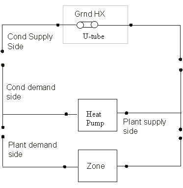
Figure 68. Schematic of EnergyPlus Ground Loop Heat Exchanger
The data definition for the ground loop heat exchanger from the Energy+.idd is shown below. The syntax to the specification of Borehole, U-tube and ground are illustrated in the example following.
This alpha field contains the identifying name for the ground heat exchanger (GHE).
This alpha field contains the ground heat exchanger inlet node name.
This alpha field contains the ground heat exchanger outlet node name.
This numeric field contains the GHE maximum design flow rate in cubic meters per second {m3/s}.
This numeric field contains the number of bore holes in the GHE installation.
This numeric field contains the length of the borehole in meters {m}.
This numeric field contains the radius of the borehole in meters.
This numeric field contains the thermal conductivity of the ground in W/m-K.
This numeric field contains the thermal heat capacity of the ground in J/m3-K.
This numeric field contains the far field temperature of the ground in °C.
This numeric field contains the design volume flow rate of the GHE in m3/s.
This numeric field contains the thermal conductivity of the filler material in W/m-K.
This numeric field contains the thermal conductivity of the pipe in W/m-K.
This numeric field contains the outer diameter of the U-tube (pipe) in meters {m}.
This numeric field contains the distance between the two legs of the U-tube in meters {m}.
This numeric field contains the outer diameter of the U-tube (pipe) in meters.
This numeric field contains the maximum number of years of simulation to be carried out.
The G-Functions may be formulated slightly differently based on the program which calculated them. The “raw” G-Functions are based on an borehole radius to active length ratio of 0.0005. If the physical ratio is different from this, a correction must be applied. If the G-Functions have not had a correction applied, use a value of 0.0005 in this field. If the correction has not been applied, use the actual radius/length ratio in this field, so that the correction will not be re-applied.” The software GLHEPro has been making this “pre-correction” to the data sets since version 3.1 of that software, so this input field should match the actual (physical) radius/length ratio.
The borehole response is defined by a non-dimensional ‘G-function’. This is specified as a series of data points giving values of non-dimensional time vs G-function value (LNTTS1, GFUNC1), (LNTTS2, GFUNC2), (LNTTS3, GFUNC3) …….. (LNTTSn, GFUNCn), This numeric field contains the number of data pairs to be read in (n).
This numeric field contains the natural log of time/steady state time: ln(T/Ts)
This numeric field contains the G-function value of the corresponding LNTTS.
The following is an example input:
GroundHeatExchanger:Vertical,
Vertical Ground Heat Exchanger, !- Name
GHE Inlet Node, !- Inlet Node Name
GHE Outlet Node, !- Outlet Node Name
0.00330000, !- Maximum Flow Rate {m3/s}
120, !- Number of Bore Holes
76.2, !- Bore Hole Length {m}
.635080E-01, !- Bore Hole Radius {m}
.692626E+00, !- Ground Thermal Conductivity {W/m-K}
.234700E+07, !- Ground Thermal Heat Capacity {J/m3-K}
13.375, !- Ground Temperature {C}
0.0033, !- Design Flow Rate {m3/s}
.692626E+00, !- Grout Thermal Conductivity {W/m-K}
.391312E+00, !- Pipe Thermal Conductivity {W/m-K}
2.66667E-02, !- Pipe Out Diameter {m}
2.53977E-02, !- U-Tube Distance {m}
2.41285E-03, !- Pipe Thickness {m}
2, !- Maximum Length of Simulation
0.0005, !- G-Function Reference Ratio
35, !- Number of Data Pairs of the G Function
! The G-function is defined by the following data pairs
-15.2996, -0.348322, ! G-Function Ln(T/Ts) Value 1, G-Function G Value 1
-14.201, 0.022208, ! G-Function Ln(T/Ts) Value 2, G-Function G Value 2
-13.2202, 0.412345, ! G-Function Ln(T/Ts) Value 3, G-Function G Value 3
-12.2086, 0.867498, ! G-Function Ln(T/Ts) Value 4, G-Function G Value 4
-11.1888, 1.357839, ! G-Function Ln(T/Ts) Value 5, G-Function G Value 5
-10.1816, 1.852024, ! G-Function Ln(T/Ts) Value 6, G-Function G Value 6
-9.1815, 2.345656, ! G-Function Ln(T/Ts) Value 7, G-Function G Value 7
-8.6809, 2.593958, ! G-Function Ln(T/Ts) Value 8, G-Function G Value 8
-8.5, 2.679, ! etc, etc.
-7.8, 3.023,
-7.2, 3.32,
-6.5, 3.681,
-5.9, 4.071,
-5.2, 4.828,
-4.5, 6.253,
-3.963, 7.894,
-3.27, 11.82,
-2.864, 15.117,
-2.577, 18.006,
-2.171, 22.887,
-1.884, 26.924,
-1.191, 38.004,
-0.497, 49.919,
-0.274, 53.407,
-0.051, 56.632,
0.196, 59.825,
0.419, 62.349,
0.642, 64.524,
0.873, 66.412,
1.112, 67.993,
1.335, 69.162,
1.679, 70.476,
2.028, 71.361,
2.275, 71.79,
3.003, 72.511; !- 35 PAIRS
The pond heat exchanger model represents a shallow pond with submerged hydronic tubes through which the heat transfer fluid is circulated. The model represents a 'shallow' pond in that no attempt is made to model any stratification effects that may be present in deeper ponds.
This type of heat exchanger is intended to be connected to the supply side of a condenser loop, and can be used with any type of plant loop. The pond may be specified as the only heat exchanger on the condenser loop (as shown in Figure 69) or it may be connected in parallel with other condenser loop heat exchangers (such as cooling towers, ground surface heat exchangers) as shown in the second figure below.

Figure 69. Example of Pond Ground Heat Exchanger as only heat exchanger on condenser loop

Figure 70. Pond Ground Heat Exchanger with other heat exchangers on condenser loop
This alpha field contains the identifying name for the outside pond heat exchanger.
This alpha field contains the fluid inlet node name.
This alpha field contains the fluid outlet node name.
This numeric field contains the pond depth {m}.
This numeric field contains the pond area {m2}.
This numeric field contains the hydronic tubing inside diameter {m}.
This numeric field contains the hydronic tubing outside diameter {m}.
This numeric field contains the hydronic tubing thermal conductivity in W/mK.
This numeric field contains the ground thermal conductivity in W/m2K.
This numeric field contains the number of hydronic tubing circuits, total in parallel in this pond..
This numeric field contains length {m} of each hydronic tubing circuit.
An example of the IDF is shown below.
GroundHeatExchanger:Pond,
Pond 1, !- Name
Condenser Tower 1 Inlet Node, !- Fluid Inlet Node Name
Condenser Tower 1 Outlet Node, !- Fluid Outlet Node Name
2.0, !- Pond Depth {m}
1000.0, !- Pond Area {m2}
0.02, !- Hydronic Tubing Inside Diameter {m}
0.025, !- Hydronic Tubing Outside Diameter {m}
0.4, !- Hydronic Tubing Thermal Conductivity {W/m-K}
1.0, !- Ground Thermal Conductivity {W/m2-K}
10, !- Number of Tubing Circuits
50.0; !- Length of Each Tubing Circuit {m}
HVAC,Average,Pond Ground Heat Exchanger Heat Transfer Rate[W]
HVAC,Sum,Pond Ground Heat Exchanger Energy[J]
HVAC,Average,Pond Ground Heat Exchanger Mass Flow Rate[kg/s]
HVAC,Average,Pond Ground Heat Exchanger Inlet Temp[C]
HVAC,Average,Pond Ground Heat Exchanger Outlet Temp[C]
HVAC,Average,Pond Ground Heat Exchanger Bulk Temp[C]
These outputs are the pond ground heat exchanger heat transfer rate and total energy exchange for the timestep.
These outputs are the pond fluid inlet and outlet temperatures and mass flow rate.
This output is the pond bulk temperature.
The surface heat exchanger model is to simulate hydronic surface ground heat exchangers. This includes pavement surfaces with embedded pipes for snow-melting or heat rejection from hybrid ground source heat pump systems.
The heat exchanger may be ground coupled or not. In the latter case the bottom surface is exposed to the wind but not solar gains. This type of heat exchanger is intended to be connected to the supply side of a condenser loop, and can be used with any type of plant loop. The surface heat exchanger may be specified as the only heat exchanger on the condenser loop (as shown in the first figure below) or it may be connected in parallel with other condenser loop heat exchangers (such as cooling towers, ground surface heat exchangers) as shown in the second figure below.
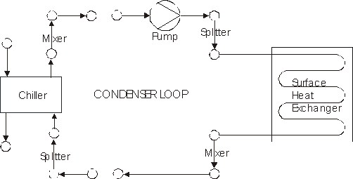
Figure 71. Example of Surface Ground Heat Exchanger as only heat exchanger on condenser loop
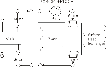
Figure 72. Surface Ground Heat Exchanger with other heat exchangers on condenser loop
This alpha field contains the identifying name for the outside panel heat exchanger.
This alpha field contains the construction name. It must contain a valid “Construction” name that is usual for Surfaces. (Ref: Group – Surface Construction Elements).
This alpha field contains the fluid inlet node name.
This alpha field contains the fluid outlet node name.
This numeric field contains the hydronic tubing inside diameter in m.
This numeric field contains the number of hydronic tubing circuits.
This numeric field contains the hydronic tube spacing in m.
This numeric field contains the surface length in m.
This numeric field contains the surface width in m.
This alpha field expresses the lower surface exposure: Exposed or Ground.
An example of this statement in an IDF is shown below:
GroundHeatExchanger:Surface,
SURFACE 1, !- Name
Outside Surface Construction, !- Construction Name
Condenser Tower 1 Inlet Node, !- Fluid Inlet Node Name
Condenser Tower 1 Outlet Node, !- Fluid Outlet Node Name
0.02, !- Hydronic Tubing Inside Diameter {m}
10.0, !- Number of Tubing Circuits
0.3, !- Hydronic Tube Spacing {m}
100.0, !- Surface Length {m}
100.0, !- Surface Width {m}
GROUND; !- Lower Surface Environment
HVAC,Average,Surface Ground Heat Exchanger Heat Transfer Rate[W]
HVAC,Average,Surface Ground Heat Exchanger Surface Heat Transfer Rate[W]
HVAC,Sum,Surface Ground Heat Exchanger Energy[J]
HVAC,Average,Surface Ground Heat Exchanger Mass Flow Rate[kg/s]
HVAC,Average,Surface Ground Heat Exchanger Inlet Temp[C]
HVAC,Average,Surface Ground Heat Exchanger Outlet Temp[C]
HVAC,Average,Surface Ground Heat Exchanger Top Surface Temp[C]
HVAC,Average Surface Ground Heat Exchanger Bottom Surface Temp[C]
HVAC,Average,Surface Ground Heat Exchanger Top Surface Flux [J/m2]
HVAC,Average,Surface Ground Heat Exchanger Bottom Surface Flux[J/m2]
HVAC,Sum,Surface Ground Heat Exchanger Surface Energy[J]
HVAC,Average,Surface Ground Heat Exchanger Source Temp[C]
These outputs are the source heat transfer rate, surface heat transfer rate and the total source energy input for the timestep.
These outputs are the surface heat exchanger fluid inlet and outlet temperatures and mass flow rate.
These outputs are the surface heat exchanger top and bottom surface temperatures.
These outputs are the surface heat exchanger top and bottom surface flux.
This is the total surface energy exchange for the timestep.
This is the surface heat exchanger source temperature.
This component is intended to be used in a condenser loop to simulate the effect of coupling the condenser and plant loops directly. For example, to bypass a chiller and couple the chilled water loop to the condenser loop so that the chilled water loop uses a cooling tower as its cooling source. This component is accordingly connected to both plant and condenser water loops (in a similar way to a chiller). The component acts to switch on and off the specified chiller/heat pump according to specified criteria (either a setpoint schedule, outside drybulb or wetbulb temperatures). The heat exchanger may be operated either in ideal or UA-effectiveness mode. In the UA-effectiveness mode the actual heat transfer between loops is calculated according to the UA-effectiveness method assuming counter flow. In ideal mode the maximum possible heat transfer is calculated. In this case, if both fluids are the same type and the loop flow rates are the same, operation is if the loops are directly coupled.
The specified plant component (chiller) is switched off and coupling enabled when either the drybulb, wetbulb or condenser loop temperature falls below the scheduled temperature. Any setpoint schedule can be specified. The usual way to operate a chiller would be to specify the schedule the same as the chilled water loop temperature and operate in ‘loop’ mode. In this way the loops would be connected when condenser water was available at or below the chilled water temperature.
This alpha field contains the unique identifying name of this component.
This alpha field contains the unique identifying name of the component under the control of the heat exchanger (e.g. the corresponding chiller).
This alpha filed contains the ‘type’ of the component under the control of the heat exchanger (e.g. Chiller:ConstantCOP).
This alpha field contains the name of the setpoint schedule that is being used to control the heat exchanger.
This alpha field contains the name of the inlet node on the condenser loop.
This alpha field contains the name of the outlet node on the condenser loop.
This alpha field contains the name of the inlet node on the plant loop.
This alpha field contains the name of the outlet node on the plant loop.
This alpha field determines the control mode. Free cooling (coupling) is enabled depending on the comparison of the scheduled temperature with the temperature defined here (drybulb, wetbulb or condenser loop). For example, specifying outside wetbulb here, free cooling would be enabled if the wetbulb temperature fell below the scheduled temperature. Options are: DryBulbTemperature, WetBulbTemperature, Schedule, or Loop. The default is Loop.
This alpha field contains the name of the setpoint schedule for the heat exchanger.
The heat exchanger can operate as either an ideal heat exchanger (the max possible energy is transferred across the loops) or as specified by the UA and effectiveness. The options are correspondingly Ideal and UFactorTimesAreaEffectiveness. Effectiveness is calculated assuming counter-flow. The default is Ideal.
This numerical field is used to specify the overall UA {W/K} for use in the calculation of actual heat transfer when in UFactorTimesAreaEffectiveness mode.
This numerical field is used to specify the design flow rate {m3/s} of this component on the condenser side. This would normally be the same as the loop/cooling tower flow rate.
This numerical field is used to specify the design flow rate {m3/s} of this component on the plant side. This would normally be the same as the loop/chiller flow rate.
This alpha field contains the name of the inlet node on the condenser loop for the component being controlled by the heat exchanger.
This alpha field contains the name of the outlet node on the condenser loop for the component being controlled by the heat exchanger.
This alpha field contains the name of the inlet node on the plant loop for the component being controlled by the heat exchanger.
This alpha field contains the name of the outlet node on the plant loop for the component being controlled by the heat exchanger.
An example of the model’s input from an idf file is shown below.
HeatExchanger:Hydronic,
Free Cooler, ! component name
Main Chiller, ! controlled component
Chiller:ConstantCOP, ! controlled component type
CW Loop Temp Schedule, ! controllled component setpoint schedule
Free Cooler Condenser Inlet Node, !- Condenser Inlet Node Name
Free Cooler Condenser Outlet Node, !- Condenser Outlet Node Name
Free Cooler Inlet Node, !- Chilled Water Inlet Node Name
Free Cooler Outlet Node, !- Chilled Water Outlet Node Name
Loop, ! Free cooling control mode
! (outside wetbulb, outside drybulb, setpoint schedule)
Free Cooling Schedule, ! This schedule name is no longer used
Ideal, ! Heat exchange mode
150000.0, !100.0, ! Heat exchanger UA
0.0086, ! Heat exchanger condenser side design flow rate.
0.0086, ! Heat exchanger plant side design flow rate.
Main Chiller Condenser Inlet Node, !- Controlled equipment condenser side inlet node
Main Chiller Condenser Outlet Node, !- Controlled equipment condenser side outlet node
Main Chiller Inlet Node, !- Controlled equipment plant side inlet node
Main Chiller Outlet Node; !- Controlled equipment plant side outlet node HEAT
HVAC,Average,Free Cooling Heat Exchanger Heat Transfer Rate[W]
HVAC,SUM,Free Cooling Heat Exchanger Heat Transfer Energy[J]
HVAC,Average,Free Cooling Heat Exchanger Condenser Side Mass Flow rate[kg/s]
HVAC,Average,Free Cooling Heat Exchanger Plant Side Mass Flow rate[kg/s]
HVAC,Average,Free Cooling Heat Exchanger Condenser Side Inlet Temp[C]
HVAC,Average,Free Cooling Heat Exchanger Condenser Side Outlet Temp[C]
HVAC,Average,Free Cooling Heat Exchanger Plant Side Inlet Temp[C]
HVAC,Average,Free Cooling Heat Exchanger Plant Side Outlet Temp[C]
HVAC,Sum,Debug Free Cooling Heat Exchanger Coupling Status[]
The heat transfer rate between the plant and condenser loops via the heat exchanger.
The heat transfer energy between the plant and condenser loops via the heat exchanger in Joules. This is on Metered on EnergyTransfer with an End Use of FreeCooling.
The flow rates in each loop.
The inlet and outlet temperatures on each side of the component.
This component is intended to couple two condenser loops, so that the effect of connecting heating/cooling equipments in series in a branch can be achieved, as is the case required by some hybrid systems. The component is connected to the supply side of one condenser loop and to the demand side of the second condenser loop. The coupling and uncoupling of two loops is achieved based on control equipment defined in the input file. The heat exchanger can be a single component on a branch or can be connected to any other condenser equipment. The heat transfer is calculated as in the case of hydronic free cooling heat exchanger. The figure below shows a typical hybrid system, which uses a Plate heat exchanger to couple two condenser loops.
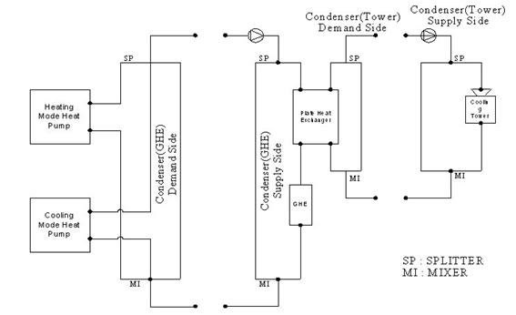
Figure 73. Plate Heat Exchanger (hybrid)
This alpha field contains the unique identifying name of this component.
This alpha field is the name of the component, which allows the plate heat exchanger to decide whether the loops have to be coupled or not. If this component is ON, the loops are coupled else the loops are uncoupled.
This alpha field tells the type of the component with the name given in the previous field.
This alpha field contains the name of the inlet node on the condenser demand side connected to the heat exchanger.
This alpha field contains the name of the outlet node on the condenser demand side connected to the heat exchanger.
This alpha field contains the name of the inlet node on the Condenser supply side connected to the heat exchanger.
This alpha field contains the name of the outlet node on the Condenser supply side connected to the heat exchanger.
The heat exchanger can operate as either an ideal heat exchanger (the max possible energy is transferred across the loops) or as specified by the UA and effectiveness. The options are correspondingly Ideal and UFactorTimesAreaEffectiveness. Effectiveness is calculated assuming counter-flow. The default is Ideal.
This numerical field is used to specify the overall UA for use in the calculation of actual heat transfer when in UFactorTimesAreaEffectiveness mode.
This numerical field is used to specify the design flow rate of this component on the Demand side. This would normally be the same as the loop/cooling tower flow rate.
This numerical field is used to specify the design flow rate of this component on the Supply side. This would normally be the same as the loop flow rate.
An example of the model’s input from an idf file is shown below.
HeatExchanger:Plate,
Plate Heat Exchanger, !- Name of free cooling heat exchanger
Cooling Tower, !- Controlled component name
CoolingTower:SingleSpeed, !- Controlled component type
PHE Demand Inlet Node, !- Condenser Side fluid Inlet Node
PHE Demand Outlet Node, !- Condenser Side fluid Outlet Node
PHE Supply Inlet Node, !- Plant side fluid inlet node
PHE Supply Outlet Node, !- Plant side fluid outlet node
UFactorTimesAreaEffectiveness, !- Heat exchange mode
571, !- UA
0.000505, !- condenser side flow rate {m3/s}
0.000505; !- plant side flow rate {m3/s}
HVAC,Average,Plate Heat Exchanger Heat Transfer Rate[W]
HVAC,Average, Plate Heat Exchanger Demand Side Mass Flow rate[kg/s]
HVAC,Average, Plate Heat Exchanger Supply Side Mass Flow rate[kg/s]
HVAC,Average, Plate Heat Exchanger Demand Side Inlet Temp[C]
HVAC,Average, Plate Heat Exchanger Demand Side Outlet Temp[C]
HVAC,Average, Plate Heat Exchanger Supply Side Inlet Temp[C]
HVAC,Average, Plate Heat Exchanger Supply Side Outlet Temp[C]
The heat transfer rate between the loops connected via the heat exchanger.
The flow rates in each loop.
The inlet and outlet temperatures on each side of the component.
The heat exchanger model designed primarily to support the simulation of plant waterside economizers, but is also suitable for other plant applications. Three types of heat exchangers can be selected: 1.) Plate frame, 2.) Single pass counter-flow and 3.) Single pass parallel-flow. The heat transfer rate is calculated using the UA-effectiveness method. An appropriate effectiveness-NTU correlation is used for each type of heat exchanger. The maximum possible heat transfer rate can be used in the simulation by specifying an Ideal heat exchanger. For this case an effectiveness of 1.0 is used.
This alpha field contains the unique identifying name of this component.
This alpha field identifies the type of heat exchanger. Heat exchanger type is specified by one of the following key words:
PlateFrame: specifies a plate-frame heat exchanger. The effectiveness will be calculated using a plate frame heat exchanger correlation. Currently this type of heat exchanger is approximated as cross flow with both streams unmixed
CounterFlow: specifies a counter-flow shell and tube heat exchanger. The effectiveness will be calculated using a counter-flow shell and tube heat exchanger correlation.
ParallelFlow: specifies a parallel-flow shell and tube heat exchanger. The effectiveness will be calculated using a parallel-flow shell and tube heat exchanger correlation.
Ideal: specifies an ideal heat exchanger. The effectiveness will be set to '1.0' and the specified UA will be ignored. The heat transfer rate will be calculated as the maximum possible heat transfer rate.
Name of the availability schedule for this heat exchanger.
This alpha field contains the name of the heat exchanger inlet node connected to chilled water . In typical water side economizer applications this is the Plant loop.
This alpha field contains the name of the heat exchanger outlet node connected to chilled water . In typical water side economizer applications this is the Plant loop.
This alpha field contains the name of the heat exchanger inlet node connected to the condenser . In typical water side economizer applications this is the Condenser loop.
This alpha field contains the name of the heat exchanger outlet node connected to the condenser . In typical water side economizer applications this is the Condenser loop.
This numerical field is used to specify the design (maximum) flow rate {m3/s} for the side of the heat exchanger connected to chilled water loop.
This numerical field is used to specify the design (maximum) flow rate {m3/s} for the side of the heat exchanger connected to the Condenser Loop.
This numerical field is used to specify the overall U-Factor Times Area (UA) {W/K} for use in the calculation of the heat exchanger effectiveness using the appropriate D-NTU correlation. If Ideal is specified as the heat exchanger type, the effectiveness will be set to 1.0. When set to autosize Heat Exchanger U-Factor Times Area Value is calculated based on an effectiveness of 1.0
This numerical field is the minimum temperature difference between chilled water side heat exchanger inlet and condenser side heat exchanger inlet required to turn on heat exchanger.
An example of the model’s input from an idf file is shown below.
HeatExchanger:WatersideEconomizer,
Integrated Economizer HX, !- Heat Exchanger Name
CounterFLow, !- Heat Exchanger Type
AirCooled, !- Heat Exchanger Condenser Type
CW Pump Outlet Node, !- Loop1 Inlet Node Name
Economizer Outlet Node, !- Loop1 Outlet Node Name
, !- Loop2 Inlet Node Name
, !- Loop2 Outlet Node Name
autosize, !- Loop1 Max Flow rate
autosize, !- Loop2 Max Flow rate
150000.0; !- HX UA Value
HVAC,Average, Economizer Heat Exchanger Heat Transfer Rate[W]
HVAC,SUM, Economizer Heat Exchanger Heat Transfer Energy[J]
HVAC,Average, Economizer Heat Exchanger Condenser Side Mass Flow rate[kg/s]
HVAC,Average, Economizer Heat Exchanger Plant Side Mass Flow rate[kg/s]
HVAC,Average, Economizer Heat Exchanger Condenser Side Inlet Temp[C]
HVAC,Average, Economizer Heat Exchanger Condenser Side Outlet Temp[C]
HVAC,Average, Economizer Heat Exchanger Plant Side Inlet Temp[C]
HVAC,Average, Economizer Heat Exchanger Plant Side Outlet Temp[C]
The heat transfer rate between the plant and condenser loops via the heat exchanger.
The heat transfer energy between the plant and condenser loops via the heat exchanger in Joules. This is on Metered on EnergyTransfer with an End Use of FreeCooling.
The flow rates in each loop.
The inlet and outlet temperatures on each side of the component.
The connector list described earlier determines how the branches of a particular loop will be hooked together. These connections can be classified either as a separation of a single stream into several outlet streams (splitter) or the merging of several streams into a single outlet stream (mixer). Due to the limitation per branch of a single splitter and a single mixer, the connector list can only have two pieces of equipment as a maximum. The names defined for either/both the splitter or/and the mixer refer then to “component” definitions as described below.
The format of both the Connector:Splitter and Connector:Mixer statements is similar. Both begin with an identifying name followed by the branch name of the “single side” of the component. In the case of the splitter, this is the inlet since the inlet stream is broken into several outlet streams. In the case of the mixer, this is the outlet since several streams are mixed together to form a single outlet. The remaining list of up to 50 names is simply the branch names of the outlet legs in the case of the splitter and inlet legs in the case of the mixer. No control logic is assume in these components—a determination of how much air to split in which direction using the splitter must be defined by other components.
This alpha field contains the identifying name for the Splitter.
This alpha field contains the identifying name for the Splitter Inlet Branch.
This alpha field contains the identifying names for the Splitter Outlet Branches and you enter as many outlet branches as needed.
This alpha field contains the identifying name for the Mixer.
This alpha field contains the identifying name for the Mixer Outlet Branch.
This alpha field contains the identifying names for the Mixer Inlet Branches and you enter as many inlet branch names as needed..
An example of these statements in an IDF is:
Connector:Splitter,
CW Loop Splitter,
CW Pump Branch,
Little Chiller Branch,
Big Chiller Branch,
Purchased Cooling Branch,
Supply Bypass Branch;
Connector:Mixer,
CW Loop Mixer,
Cooling Supply Outlet,
Little Chiller Branch,
Big Chiller Branch,
Purchased Cooling Branch,
Supply Bypass Branch;
This object is used for special cases where plant flow control is needed to make efficient use of thermal storage. In certain solar hot water and heat recovery situations, a thermal storage tank may become warmer than is necessary or allowable for safe use of the hot water. Although real installations of a tempering, or anti-scald valve, would more commonly mix a new stream of mains water with the hot water to achieve a desired outlet temperature, this is difficult to model directly within EnergyPlus because plant loops need to be closed circuits. For many installations where the water entering the splitter is directly from the mains, such as make up water entering a water heater tank, the modeling provided with this object should be thermodynamically equivalent.
The TemperingValve object models a temperature-controlled diversion valve. It models a valve on a bypass pipe that can open to divert flow around one or more plant components. It can only be used on one of two branches between a Splitter and a Mixer. The figure below shows the use of the tempering valve with a Water Heater:Mixed component on “Stream 2.” The tempering valve acts to divert flow through the branch it is on in order to adjust the temperature at the outlet of the mixer. If the temperature at Stream 2 Source Node is warmer than the setpoint and the inlet flow is cooler than the setpoint, then a controller determines how much flow should bypass the storagew tank to achieve the desired setpoint.
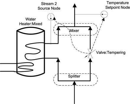
Figure 74. Tempering Valve Schematic
The TemperingValve is an Active component and the other path should have only Passive components. Only two paths in the splitter/mixer can be used; bypasses are not allowed. No other Connector:Splitter and Connector:Mixer pair can be used on the supply side of the plant loop.
This field should contain an unique name for each TemperingValve object
This field should contain the name of node which is the inlet for the valve.
This field should contain the name of node which is the outlet for the valve
This field should contain the name of node that is the inlet to the Mixer object for the second stream containing the component whose flow is being diverted.
This field should contain the name of a node that has a temperature setpoint assigned to it. A separate set point manager object is needed to provide a set point on the node listed here.
This field should contain the name of the node that is the outlet for the pump that is one the same plant loop. This is node is used to sense the total flow rate.
This object is demonstrated in the example file called SolarCollectorFlatPlateWater.idf. An example of this object is:
TemperingValve,
DHW Anti-Scald Diverter,
DHW Anti-Scald Inlet Node, ! Inlet Node Name
DHW Anti-Scald Outlet Node, ! Outlet Node Name
SHW Storage Tank Use Outlet Node, ! Stream 2 Source Node Name
DHW Instantaneous Boost Outlet Node, ! Temperature Setpoint Node Name
DHW Use Side Pump Outlet; ! pump outlet node
Use report variables for System Nodes for flow and temperature results.
Air loops along with zone equipment form the entire forced air heating and cooling system (air side). The main statement for defining an air loop is the AirLoopHVAC object described here. As with the main plant and condenser statements, several of the items in the AirLoopHVAC object definition are actually names that refer to other objects in the input file. After the AirLoopHVAC object name, four such list pointers are encountered: for controllers, system availability, branches, and connectors. The Controller List defines how the air loop will respond due to various inputs (control signals). The Availability Manager List refers to methods for controlling when a system is operational. This may be as simple as a schedule to define when the system is shutdown. The Branch List lists the branches that comprise the primary air system. Finally, the Connector List lists the connections between the branches. The branches and connections together define the primary air system topology.
The only numeric input is the design primary air flow rate. This item is input just before the BranchList name.
The next series of names refer to nodes for the various inlet and outlet points of the air loop. The air loop starts where the zone equipment ends. This is a single point consisting of the return air duct once all of the zone return air streams have been collected. While in reality, there is really only one point, for clarity within the simulation components and consistency with the other HVAC loop sections, this point in the systems is defined as two points: one that resides with the zone equipment simulation and one that is acted upon by the air loop simulation. Both node names must be entered into the input file, and both nodes must have unique names. Similarly, the end points of the air loop that also correspond to the beginning points of the zone equipment loop must also be defined. These consist of names referencing lists of up to three pairs of node names as shown below. Up to three air loop outlets are allowed to accommodate the simulation of three deck systems.
This field is a unique, user assigned name for a single instance of an AirLoopHVAC object. Any other object referencing this AirLoopHVAC will use this name.
This field is the name of a ControllerList object. A Controller List is simply a list of controllers giving both controller name and type. This Controller List specifies all the controllers that will act on this primary air loop. The order of the controllers in the list is significant: controllers are simulated sequentially in the order given in the Controller List.
This field is the name of a AvailabilityManagerList object. A Availability Manager List is a list of Availability Managers giving both Availability Manager type and name. The availability managers in the list apply to this primary air loop. That is, they determine when and if this air loop is on or off, overriding the control provided by the central fan on/off schedule.
This is the system primary air design volumetric flow rate in cubic meters per second.
This field is the object name of a BranchList object (see BranchList and Branch). The BranchList named here specifies all the branches composing the primary air system. These branches, together with the Connectors listed in the ConnectorList, define the primary air system topology.
This field is the name of ConnectorList object. This ConnectorList object lists all the Connectors (by type and name) that are included in this primary air system. These Connectors, together with the Branches in the BranchList, define the topology of the primary air system.
The name of the air entrance node of this primary air system. This is the inlet node for return air for this air system.
The name of the air outlet node for the zone equipment group (ZoneHVAC:EquipmentConnections objects) attached to the primary air system. This should be the outlet node of a AirLoopHVAC:ZoneMixer in the AirLoopHVAC:ReturnPath for the zone equipment group attached to this primary air system.
This field can be the name of a node which is the air inlet node for the zone equipment group (see ZoneHVAC:EquipmentConnections objects) attached to this primary air system. Or, this field can be the name of a node list containing one or more nodes (up to 3). These nodes should be the inlet nodes to the AirLoopHVAC:ZoneSplitter or AirLoopHVAC:SupplyPlenum in each of the AirLoopHVAC:SupplyPaths for the zone equipment groups attached to this primary air system. For single duct systems, there is only one node name in this list. For two and three duct systems, the order of the nodes in this list must correspond with the order of the nodes in the Supply Side Outlet Node Names list.
This field can be the name of a node which is the air outlet node for each supply duct of this primary air system. Or, this field can be the name of a node list containing one or more nodes (up to 3). The list can contain the names of up to three nodes. For single duct systems, there is only one node name in this list. For two and three duct systems, the order of the nodes in this list must correspond with the order of the nodes in the Demand Side Inlet Node Names list.
An example of this statement in an IDF is:
AirLoopHVAC,
Main Dual Duct Air Loop, ! Primary Air Loop Name
Dual Duct System 1 Controllers, ! Controller List
Dual Duct System 1 Schedule List , ! System Availability Manager List
1.3 , ! Primary air design volumetric flow rate
Dual Duct Air Loop Branches , ! Air Loop Branch List Name
Dual Duct Connectors , ! Air Loop Connector List Name
Supply Fan Inlet Node , ! ReturnAir AirLoop Inlet Node
Return Air Mixer Outlet , ! ZoneEquipGroup Outlet Node
Zone Equipment Inlet Node List , ! SupplyAirPath ZoneEquipGroup Inlet Nodes
Air Loop Outlet Node List ; ! AirLoop Outlet Nodes
HVAC,Average,Air Loop System Cycle On/Off Status
HVAC,Sum,HVACManage Iterations []
HVAC,Sum,AirLoop-Zone Iterations []
HVAC,Sum,Max SimAir Iterations []
HVAC,Sum,Tot SimAir Iterations []
HVAC,Sum,Tot SimAirLoopComponents Calls []
This field is the availability status of an AirLoopHVAC. This status flag is a result of the calculations made by the System Availability Manager(s) listed in a System Availability Manager List. When a single availability manager is used in a System Availability Manager List, this is also the availability status reported by the specific availability manager (Ref. System Availability Manager Outputs). When multiple availability managers are used in a System Availability Manager List, the loop availability status is determine by the rules associated with AirLoopHVACs (see rules described for Group – System Availability Managers). The control status outputs are represented using integers 0 through 3.. These integers represent NoAction (0), ForceOff (1), CycleOn (2), and CycleOnZoneFansOnly (3). Since the status output is averaged, the output result may not correspond to the values described here when report variable frequencies other than detailed are used. Use the “detailed” reporting frequency (Ref. Report Variable) to view the availability status at each simulation timestep.
These variables are simply counters of how many iterations were executed. The count for any given HVAC time step will be the iterations executed before convergence was achieved, or the max allowed in which case the simulation throws a warning and proceeds to the next time step.
This section provides more detailed information on the reporting available for outdoor air ventilation. Sixteen cooling and heating load variables and eight energy summary variables are available that report the impact of system outdoor air on zone loads, system demand and total energy use. The representative air system shown in the diagram below shows outdoor air (OA), return air (RA), supply air (SA) and mixed air (MA).
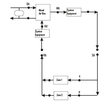
Figure 75. Example System for Ventilation Loads Report
The overall effect of outdoor air on the system shown above can be summarized by considering the mixing box. In this system, part or all of the return air is replaced by outdoor air. The presence of any heat recovery will already be taken into account and thus will automatically be accounted for by using the outdoor air inlet conditions to the mixing box (point OA in the diagram) rather than actual outdoor air conditions. Thus, the overall energy impact of outdoor air (ventilation) on a particular system can be evaluated by multiplying the outdoor air mass flow rate by the enthalpy difference between the outdoor air entering the mixing box (OA) and the return air entering the mixing box (RA’) as shown in the following equation.
![]()
The fresh air flow into each zones are reported using the ventilation flow report variables. The total outdoor air flow in a primary air system is divided to each zone based on the fraction of flow each zone is supplied. There are six variables which deals with the mechanical ventilation flow reporting. Those six variables are:
Reports the average outdoor air mass flow rate to any zone over the reporting interval.
Reports the total outdoor air mass that has been supplied to any zone over the reporting interval.
Reports the average outdoor air volume flow rate to any zone over the reporting interval, calculated using a standard density for air. Standard density in EnergyPlus corresponds to 20ºC drybulb, dry air, and nominally adjusted for elevation.
Reports the total outdoor air volume that has been supplied to a zone over the reporting interval, calculated using a standard density for air. Standard density in EnergyPlus corresponds to 20ºC drybulb, dry air, and nominally adjusted for elevation.
Reports the average outdoor air volume flow rate to any zone over the reporting interval, calculated using the current density for zone air.
Reports the total outdoor air volume that has been supplied to a zone over the reporting interval, calculated using the current density for zone air.
Reports the air changes per hour in the zone due to the outside fresh air supplied by mechanical ventilation system.
The example syntax below shows the basic ventilation flow variables reported on an hourly basis.
Output:Variable,*,Zone Mechanical Ventilation Mass Flow Rate,Hourly;
Output:Variable,*,Zone Mechanical Ventilation Mass,Hourly;
Output:Variable,*,Zone Mechanical Ventilation Volume Flow Rate Standard Density,Hourly;
Output:Variable,*,Zone Mechanical Ventilation Volume Standard Density,Hourly;
Output:Variable,*,Zone Mechanical Ventilation Volume Flow Rate Current Density,Hourly;
Output:Variable,*,Zone Mechanical Ventilation Volume Current Density,Hourly;
Output:Variable,*,Zone Mechanical Ventilation Ventilation Air Change Rate,Hourly;
The impact of system outdoor air on a particular zone may be calculated by summing the mass flow weighted ![]() over the supply air paths (both cooling and heating) serving the zone as follows:
over the supply air paths (both cooling and heating) serving the zone as follows:
![]()
Four report variables each for cooling and heating report the impact of the ventilation air on the zone load in the absence of ventilation air system interactions. The ventilation load report variables are:
The cooling/heating load that would occur once ventilation air met the zone cooling/heating load and continued to overcool/overheat the zone. No system effects are accounted for.
The decrease in zone cooling/heating load that would occur as a result of ventilation air introduced directly into the zone. No system effects are accounted for.
The addition or removal of heat to a zone with no load. The heat addition or removal is due to mechanical ventilation while the zone thermostat is in the deadband.
To summarize:
Cooling:
1. Zone Mechanical Ventilation No Load Heat Removal [J]
Cooling that would be provided directly to zone by ventilation air. Ventilation occurred with no zone load.
2. Zone Mechanical Ventilation Cooling Load Increase [J]
The increase in zone cooling load that would occur as a result of ventilation air introduced directly into the zone. No system effects are accounted for.
3. Zone Mech Ventilation Cooling Load Increase: OverHeating [J]
The cooling load that would occur once ventilation air met the zone heating load and continued to overheat the zone. No system effects are accounted for.
4. Zone Mechanical Ventilation Cooling Load Decrease [J]
The decrease in zone cooling load that would occur as a result of ventilation air introduced directly into the zone. No system effects are accounted for.
Heating:
1. Zone Mechanical Ventilation No Load Heat Addition [J]
Heating that would be provided directly to zone by ventilation air. Ventilation occurred with no zone load.
2. Zone Mechanical Ventilation Heating Load Increase [J]
The increase in zone heating load that would occur as a result of ventilation air introduced directly into the zone. No system effects are accounted for.
3. Zone Mech Ventilation Heating Load Increase: OverCooling[J]
The heating load that would occur once ventilation air met the zone cooling load and continued to overcool the zone. No system effects are accounted for.
4. Zone Mechanical Ventilation Heating Load Decrease [J]
The decrease in zone heating load that would occur as a result of ventilation air introduced directly into the zone. No system effects are accounted for.
The report variables are calculated by comparing the zone ventilation load with the zone cooling or heating load. ‘Ventilation cooling’ decreases the zone cooling load until the cooling load has been eliminated. The remaining ‘ventilation cooling’ is reported as ‘overcooling’. ‘Overheating’ is calculated in the same manner. The actual system operation, which determines whether or not an ‘overcooling’ or ‘overheating’ load actually results in increased energy consumption, is not considered in the calculation of these report variables.
The ventilation zone load report variables are shown in Table 24. The variables report the maximum potential “cost” or “benefit” of ventilation air introduced directly into the zone.
Table 24. Ventilation Load Report Variables
|
|
No Zone Load |
Zone Cooling Load |
Zone Heating Load |
|
Ventilation Cooling |
Zone Mechanical Ventilation No Load Heat Removal |
Zone Mechanical Ventilation Cooling Load Decrease |
Zone Mechanical Ventilation Heating Load Increase |
|
Zone Mech Ventilation Heating Load Increase: OverCooling |
|||
|
Ventilation Heating |
Zone Mechanical Ventilation No Load Heat Addition |
Zone Mechanical Ventilation Cooling Load Increase |
Zone Mechanical Ventilation Heating Load Decrease |
|
Zone Mech Ventilation Cooling Load Increase: OverHeating |
The example syntax below shows the basic ventilation load variables reported on a monthly basis.
Output:Variable,*,Zone Mechanical Ventilation Heating Load Increase,monthly;
Output:Variable,*,Zone Mechanical Ventilation Heating Load Decrease,monthly;
Output:Variable,*,Zone Mechanical Ventilation No Load Heat Addition,monthly;
Output:Variable,*,Zone Mechanical Ventilation Cooling Load Increase,monthly;
Output:Variable,*,Zone Mechanical Ventilation Cooling Load Decrease,monthly;
Output:Variable,*,Zone Mechanical Ventilation No Load Heat Removal,monthly;
Reporting on a timestep or hourly level would produce a detailed report with variables intermingled with the other report variables that might be requested in the input file.
Another method will more easily encapsulate the report:
OutputControl:Table:Style,
HTML; !- ColumnSeparator
Output:Table:Monthly,
Ventilation Loads, !- Name
, !- DigitsAfterDecimal
Zone Mechanical Ventilation No Load Heat Removal, SumOrAverage,
Zone Mech Ventilation Cooling Load Increase: OverHeating, SumOrAverage,
Zone Mechanical Ventilation Cooling Load Decrease, SumOrAverage,
Zone Mechanical Ventilation Cooling Load Increase, SumOrAverage,
Zone Mechanical Ventilation No Load Heat Addition, SumOrAverage,
Zone Mech Ventilation Heating Load Increase: OverCooling, SumOrAverage,
Zone Mechanical Ventilation Heating Load Decrease, SumOrAverage,
Zone Mechanical Ventilation Heating Load Increase, SumOrAverage;
This combination will report the ventilation loads on a monthly basis in a HTML style report that can be easily read in a web browser. Review the Output:Table:Monthly object for other methods of display or further options on this report item.
Most report variables are a single entity reporting. Meters are a combination of like variables – specifically for Energy Consumption. This section introduces a slightly different concept – where report variables described herein are a combination of several similar items – specifically targeted at HVAC/System level reporting. This reporting is coupled with an Air Loop (ref: AirLoopHVAC)
All items shown in this section are typical “report variables” and can be reported with the Output:Variable object.
Or, as is shown by example here, perhaps a more readable form is to generate them in Tabular Form with the “Report Table Monthly” object.
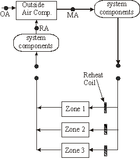
Figure 76. View of System Level Reporting
In this category, the total system load is reported. Two aspects are reported here: Heating and Cooling. The following two variables report the heat energy that system components (including packaged equipment, fans, main coils, reheat coils, humidifiers, desiccant dehumidifiers, evaporative coolers and heat exchangers) add or remove from the air loop. Each variable within these grouping wil
Heat Addition to the Air Loop (Sum of all components) in Joules
Heat Removal from the Air Loop (Sum of all components) in Joules
In ‘Output:Table:Monthly’ format shown below.
OutputControl:Table:Style ,
HTML; !- ColumnSeparator
Output:Table:Monthly,
System Loads, !- Name
, !- DigitsAfterDecimal
Air Loop Total Heating Energy, SumOrAverage,
Air Loop Total Cooling Energy, SumOrAverage;
System Energy Use consists of six output variables that report the total energy (in Joules) and water consumption (in m3) for all system components and including packaged equipment, fans, main coils, reheat coils, humidifiers, desiccant dehumidifiers, and evaporative coolers. The output variables shown below show hot and cold water, steam, electric and gas energy. Hot and cold water energy includes all ‘district cooling’ and ‘district heating’ energy.
Hot Water Consumption for the system (Joules).
Steam Consumption for the system (Joules).
Chilled Water Consumption for the system (Joules).
Electric Consumption for the system (Joules).
Gas (Natural Gas and Propane) Consumption for the system (Joules).
Water Consumption for the system (humidifiers and evaporative coolers) (m3).
The Standard reports file includes these variables reporting in the Tabular report form as “Air Loop System Energy and Water Use”.
OutputControl:Table:Style,
HTML; !- ColumnSeparator
Output:Table:Monthly,
Air Loop System Energy and Water Use, !- Name
, !- DigitsAfterDecimal
Air Loop Hot Water Consumption , SumOrAverage,
Air Loop Steam Consumption , SumOrAverage,
Air Loop Chilled Water Consumption, SumOrAverage,
Air Loop Electric Consumption, SumOrAverage,
Air Loop Gas Consumption, SumOrAverage,
Air Loop Water Consumption, SumOrAverage;
Reporting System Component Loads shows the energy transferred to or extracted from the air loop by system component type. Fans, Cooling Coils, Heating Coils, Heat exchangers, humidifiers, evaporative coolers, and desiccant dehumidifiers show heat transfer rates in Joules. The components may be located in outdoor air systems bundled with packaged equipment or specified as stand-alone components. The reporting accounts for both main branch and reheat coils.
The Standard reports file includes these variables reporting in the Tabular report form as “Air Loop System Component Loads”.
OutputControl:Table:Style,
HTML; !- ColumnSeparator
Output:Table:Monthly,
Air Loop System Component Loads, !- Name
, !- DigitsAfterDecimal
Air Loop Fan Heating Energy, SumOrAverage,
Air Loop Total Cooling Coil Energy, SumOrAverage,
Air Loop Total Heating Coil Energy, SumOrAverage,
Air Loop Total Heat Exchanger Heating Energy, SumOrAverage,
Air Loop Total Heat Exchanger Cooling Energy, SumOrAverage,
Air Loop Total Humidifier Heating Energy, SumOrAverage,
Air Loop Total Evap Cooler Cooling Energy, SumOrAverage,
Air Loop Total Desiccant Dehumidifier Cooling Energy, SumOrAverage;
Energy consumption for Fans (Joules)
Energy consumption for Cooling Coils (Joules)
Energy consumption for Heating Coil(s) (Joules)
Heating energy consumption for heat exchangers (Joules)
Heating energy consumption for heat exchangers (Joules)
Heating energy consumption for humidifiers (Joules)
Energy consumption for evaporative coolers (Joules)
Energy consumption for desiccant dehumidifiers (Joules)
Reporting System Component Energy Use consists of eleven output variables that report the total energy consumption (in Joules) of system components by energy type and coil type. Electric energy consumption is reported for fans, heating and cooling coils in packaged (DX) systems, electric resistance heating coils, humidifiers, evaporative coolers and desiccant dehumidifiers.
Electric consumption for fans. (Joules)
Consumption for heating coil hot water (both purchased and plant supplied) (Joules)
Consumption for cooling coil chilled water (both purchased and plant supplied) (Joules)
Compressor plus condenser fan electricity use. (Joules)
Compressor plus condenser fan electricity use. (Joules)
Electricity consumption for the heating coil. (Joules)
Gas (Propane and Natural Gas) consumption for the heating coil. (Joules)
Steam consumption for the heating coil (steam coils). (Joules)
Electricity consumption for the humidifiers. (Joules)
Electricity consumption for the evaporative coolers. (Joules)
Electricity consumption for the desiccant dehumidifiers. (Joules)
The Standard reports file includes these variables reporting in the Tabular report form as “Air Loop System Component Energy Use”.
OutputControl:Table:Style,
HTML; !- ColumnSeparator
Output:Table:Monthly,
Air Loop System Component Energy Use, !- Name
, !- DigitsAfterDecimal
Air Loop Fan Electric Consumption, SumOrAverage,
Air Loop Heating Coil Hot Water Consumption, SumOrAverage,
Air Loop Cooling Coil Chilled Water Consumption, SumOrAverage,
Air Loop DX Heating Coil Electric Consumption, SumOrAverage,
Air Loop DX Cooling Coil Electric Consumption, SumOrAverage,
Air Loop Heating Coil Electric Consumption, SumOrAverage,
Air Loop Heating Coil Gas Consumption, SumOrAverage,
Air Loop Heating Coil Steam Consumption, SumOrAverage,
Air Loop Humidifier Electric Consumption, SumOrAverage,
Air Loop Evap Cooler Electric Consumption, SumOrAverage,
Air Loop Desiccant Dehumidifier Electric Consumption, SumOrAverage;
A map for Air Loop input syntax is shown in the following diagram.
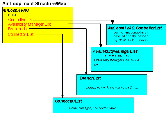
Figure 77. Air Loop Input Syntax Map
The syntax for the AirLoopHVAC:ControllerList definition is shown below. As with other lists in EnergyPlus input, the object title and identifying name are followed by type-name pairs. In this case, the types are controller types. The order in which controllers appear on this list also define the priority as described below. The identifying name refers back to the name recorded in the AirLoopHVAC statement.
The user designated unique name of an instance of a Controller List. Any object referencing this Controller List will do so using this name.
After the identifying name, input for the controller list consists of up to 8 pairs of data items: a controller type and a controller name. The first controller listed has the highest priority, the second the second highest priority, and so forth.
The type of controller. This should be a key word defining a class of controllers such as Controller:WaterCoil.
The name of a controller object (such as a Controller:WaterCoil) defined elsewhere in the input file.
An example of this statement in an IDF is:
AirLoopHVAC:ControllerList,
Dual Duct System 1 Controllers,
Controller:WaterCoil, Main Cooling Coil Controller,
Controller:WaterCoil, Main Heating Coil Controller;
The AvailabilityManagerAssignmentList defines the applicable managers used for an AirLoopHVAC or PlantLoop. The priority of availability managers is based on a set of rules and are specific to the type of loop. The output from each Availability Manager is an availability status flag. This flag can have the values NoAction, ForceOff, CycleOn, or CycleOnZoneFansOnly (used only for air loops). The availability status flags for the Availability Managers referenced by an air or plant loop are used to set the availability status flag for each loop. For the air loops, ForceOff takes precedence: if any of the loop’s availability managers are showing status ForceOff, the loop status will be ForceOff. Next in precedence is CycleOnZoneFansOnly, followed by CycleOn, and NoAction. For the plant loops, there is no precedence among the Availability Manager status flag values. Instead, the first availability manager giving a status flag value other than NoAction sets the status for the loop. The Availability Managers are executed in Availability Manager List order.
Special rules also apply for which managers may be listed in a Availability Manager list. The Hybrid Ventilation Control Manager (object: AvailabilityManager:HybridVentilation) is a special type of manager and is never specified in a Availability Manager List (it is used stand-alone for a specific air loop). All other types of availability managers may be listed in the Availability Manager List used for AirLoopHVACs. For Plant Loops, the Night Cycle and Night Ventilation managers (objects: AvailabilityManager:NightCycle and AvailabilityManager:NightVentilation) are not allowed in the Availability Manager List.
The name of the AvailabilityManagerAssignmentList object. This is referenced by AirLoopHVAC and PlantLoop objects.
Managers are listed by pairs of data items: Availability Manager Object Type and Availability Manager Name. The managers are simulated down the list and calculate a control status for use by the AirLoopHVAC or PlantLoop. The priority of each manager used for a specific loop is based on the rules described above. Availability managers are not currently used for condenser loops. The availability managers, along with the AirLoopHVAC and PlantLoop object, report the control status calculated each simulation timestep. These report variables can be used to prioritize the managers according to the required control strategy. Six managers are accomodated in the list by default, however, this IDD specification is extensible. Additional pairs may be added by directly editing the IDD.
The key word defining the type of manager, e.g. AvailabilityManager:NightCycle.
The name of a AvailabilityManager object defined elsewhere in the input file.
An example of this statement in an IDF is:
AvailabilityManagerAssignmentList,
Collector Loop Availability Manager List, !- Name
AvailabilityManager:HighTemperatureTurnOff, !- System Availability Manager Type 1
High Temperature Turn Off Availability Manager, !- System Availability Manager Name 1
AvailabilityManager:LowTemperatureTurnOn , !- System Availability Manager Type 2
Low Temperature Turn On Availability Manager, !- System Availability Manager Name 2
AvailabilityManager:DifferentialThermostat, !- System Availability Manager Type 3
Differential Thermostat Availability Manager; !- System Availability Manager Name 3
The Outside Air System (object AirLoopHVAC:OutdoorAirSystem) is a subsystem of an AirLoopHVAC. It handles the mixed air portion of the primary air system: the system relief air, the outside air inlet, and any components and controllers associated with the system relief air and outside air streams. From the perspective of the primary air loop the Outside Air System is treated as a single component. As a subsystem, it can contain one or more components and controllers.
The input for the Outside Air System consists of a system name, a controller list name, an equipment list name, and an availability manager list name. The controller list simply lists, by type and unique name, all the controllers in the subsystem. The controllers will be simulated in list order. The equipment list lists all the components in the subsystem, by type and name. The equipment is simulated in list order. Finally, the availability manager list gives the type and name of the availability managers used by the subsystem.
The equipment inlet/outlet must be sequential with no loops - the simulation can only handle a straight-through air path, both on the primary air side and on the secondary air side, if any. Heat exchanger secondary air inlets need to be independent of the primary air stream – usually relief air is used.
The unique, user assigned name for a single instance of an Outside Air System. Any other object referencing this Outside Air System will use this name.
This field is the name of a AirLoopHVAC:ControllerList object. A AirLoopHVAC:ControllerList is simply a list of controllers giving both controller name and type. This Controller List specifies all the controllers that will act on this outside air system. The order of the controllers in the list is significant: controllers are simulated sequentially in the order given in the Controller List. Typically the Controller List would contain a Controller:OutdoorAir. If there are chilled water or hot water coils in the outdoor air system, each such coil will need a Controller:WaterCoil.
This field is the name of an AirLoopHVAC:OutdoorAirSystem:EquipmentList object. An AirLoopHVAC:OutdoorAirSystem:EquipmentList is simply a list of components giving both component name and type. This Outdoor Air Equipment List specifies all the components that will be simulated in this outside air system. The order of the components in the list is significant: components are simulated sequentially in the order given in the Outdoor Air Equipment List. Typically the equipment list would contain at least an OutdoorAir:Mixer. If there is more than one component, the components must be listed in order from the outside air to the OutdoorAir:Mixer (the OutdoorAir:Mixer is last).
This field is the name of a AvailabilityManagerAssignmentList object. An Availability Manager List is a list of Availability Managers giving both Availability Manager Object Type and Name. Use of this input is optional. This field may be omitted; it is not currently used by the program.
An IDF example, including the AirLoopHVAC, and the controller and equipment lists.
AirLoopHVAC,Typical Terminal Reheat 1,
Reheat System 1 Controllers,
Reheat System 1 Avail List,
1.3,
Air Loop Branches,,
Air Loop Inlet Node, Return Air Mixer Outlet,
Zone Equipment Inlet Node, Air Loop Outlet Node;
AirLoopHVAC:ControllerList,
Reheat System 1 Controllers,
Controller:WaterCoil, Main Cooling Coil Controller;
BranchList, Air Loop Branches,
Air Loop Main Branch;
Branch, Air Loop Main Branch,
1.3,
,
AirLoopHVAC:OutdoorAirSystem, OA Sys 1,
Air Loop Inlet Node, Mixed Air Node,PASSIVE
Fan:ConstantVolume, Supply Fan 1,
Mixed Air Node, Cooling Coil Air Inlet Node, ACTIVE,
Coil:Cooling:Water:DetailedGeometry, Detailed Cooling Coil,
Cooling Coil Air Inlet Node, Air Loop Outlet Node, PASSIVE;
AvailabilityManagerAssignmentList, Reheat System 1 Avail List,
AvailabilityManager:Scheduled, Reheat System 1 Avail;
AvailabilityManager:Scheduled, Reheat System 1 Avail,
FanAndCoilAvailSched;
AirLoopHVAC:OutdoorAirSystem,
OA Sys 1,
OA Sys 1 Controllers,
OA Sys 1 Equipment;
AirLoopHVAC:ControllerList,
OA Sys 1 Controllers,
Controller:OutdoorAir, OA Controller 1;
AirLoopHVAC:OutdoorAirSystem:EquipmentList,
OA Sys 1 Equipment,
HeatExchanger:AirToAir:FlatPlate,OA Heat Recovery 1,
OutdoorAir:Mixer, OA Mixing Box 1;
The impact of using outside air/mechanical ventilation is described in the section: Outdoor Air Ventilation Report Variables.
Used to specify the components in the outdoor air system. The components will be simulated in the order in which they occur in the list.
The user designated unique name of an instance of an Air Loop Equipment List. Any object referencing this Air Loop Equipment List will do so using this name.
After the identifying name, the list consists of up to 8 pairs of data items:
This field specifies the keyword for the type of component used.
This field is the unique name of the component specified in the previous field. This named object must appear in the IDF.
An example from an IDF:
AirLoopHVAC:OutdoorAirSystem:EquipmentList,
OA Sys 1 Equipment,
HeatExchanger:AirToAir:FlatPlate,OA Heat Recovery 1,
OutdoorAir:Mixer, OA Mixing Box 1;
The OutdoorAir:Node object declares an HVAC system node for outdoor air conditions. The program automatically sets the air conditions at these nodes to correspond to the ambient environmental conditions at the beginning of every timestep. The outdoor air node is typically used as the inlet air node to an HVAC component such as the OutdoorAir:Mixer object. Multiple OutdoorAir:Node objects can be used in an input file, however, duplicate node names are not allowed.
The Height Above Ground field is used to adjust the weather file air conditions, e.g., outdoor dry-bulb and wet-bulb air temperatures, for atmospheric variation with height. This variation can become a significant factor when modeling tall buildings. See the Engineering Reference section on Atmospheric Variation for a description of the algorithm for variation of atmospheric properties with height. A blank entry or a value less than zero for this field indicates that the height will be ignored and the weather file conditions will be used.
OutdoorAir:Node and OutdoorAir:NodeList both set a node to outdoor air conditions. OutdoorAir:Node modifies the weather file conditions if a height has been specified. OutdoorAir:NodeList does not have a height input and always uses the weather file conditions without modification. The same node name may not be used with both of these objects.
The unique name for this outdoor air node.
The height [m] of the node above ground level. A value greater than zero allows the weather file conditions, e.g., outdoor dry-bulb and wet-bulb air temperatures, to be adjusted according to atmospheric variation with height.
A blank entry or value less than zero indicates that the height will be ignored and the weather file conditions will be used.
An example IDF:
OutdoorAir:Node,
OA Node 1; !- Name
OutdoorAir:Node,
Floor 10 Outdoor air Inlet Node, !- Name
30.0; !- Height Above Ground {m}
The ambient dry-bulb air temperature and flow rate at the outdoor air node can be monitored using the system node output variables:
HVAC,Average,System Node Temp[C]
HVAC,Average,System Node MassFlowRate[kg/s]
e.g.
Report Variable,
Floor 10 Outdoor air Inlet Node,
System Node Temp,
Hourly;
The program needs to know which HVAC system nodes are inlets for outdoor air. Knowing this, the program can set the conditions at these nodes to the outdoor conditions at the start of each major timestep. The OutdoorAir:NodeList provides the means for specifying which nodes are outdoor air nodes.
The input is flexible: there may be one or more OutdoorAir:NodeList in each input file. Each list contains up to 25 names. The names can be the name of a unique HVAC system node, or the name of a Node List which will contain the actual node names. Duplicate node names are ignored.
OutdoorAir:Node and OutdoorAir:NodeList both set a node to outdoor air conditions. OutdoorAir:Node modifies the weather file conditions if a height has been specified. OutdoorAir:NodeList does not have a height input and always uses the weather file conditions without modification. The same node name may not be used with both of these objects.
The name of an HVAC system node or of a NodeList object. There can be up to 25 names.
An example IDF:
OutdoorAir:NodeList,
OutsideAirInletNodes;
NodeList,OutsideAirInletNodes,
Outdoor air Inlet Node;
The OutdoorAir:Mixer is the most common component used in an outdoor air system. The outdoor air mixer has 2 inlet air streams: the system return air and the outdoor air. It has 2 outlet air streams: the system relief air and the mixed air. This is a passive component. It takes the inlet mass flows and conditions plus the relief air mass flow and calculates the mixed air flow rate and conditions (as well as the relief air conditions). The inlet and relief mass flow must be set outside the component – most commonly by an outdoor air controller. The OutdoorAir:Mixer can also be used in compound components such as a fan coil unit.
Input for this object is very simple: a unique name plus the node names of the 2 inlet nodes and the 2 outlet nodes.
A unique user assigned name for a particular outdoor air mixer component. Any reference to this component by another object will use this name.
The name of the HVAC system node which is the outlet for the mixed air stream.
The name of the HVAC system node which is the inlet for the outdoor air stream.
The name of the HVAC system node which is the outlet for the system relief air.
The name of the HVAC system node which is the inlet for the return air stream.
An IDF example:
OutdoorAir:Mixer,
Zone1WindACOAMixer, ! name
Zone1WindACOAMixerOutletNode, ! mixer outlet node
Zone1WindACOAInNode, ! mixer OA node
Zone1WindACExhNode, ! mixer relief node
Zone1WindACAirInletNode; ! mixer inlet node
The Airflow Network model provides the ability to simulate multizone airflows driven by wind and also by a forced air distribution system. The model can also simulate the heat and moisture gains or losses from the air distribution system itself (e.g., ductwork). When modeling an air distribution system, the current version of the Airflow Network model is restricted to a single forced air system (i.e., AirLoopHVAC object) with a constant volume supply air fan (Fan:ConstantVolume or Fan:OnOff). The capabilities of the model are to:
n Simulate zone pressures due to envelope leakage and forced air distribution during HVAC system fan operation
n Simulate node pressures in a forced air distribution system during HVAC system fan operation
n Calculate multizone airflows due to forced air, wind, and surface leakage, including adjacent zones and outdoors, during HVAC system fan operation
n Simulate distribution system airflows, including supply and return air leaks, during HVAC system fan operation
n Simulate air distribution system node temperatures and humidity ratios during HVAC system fan operation
n Calculate duct conduction losses during HVAC system fan operation
n Calculate vapor diffusion losses of ducts during HVAC system fan operation
n Calculate sensible and latent loads on the surrounding zones due to supply and return air leaks in the air distribution system during HVAC system fan operation
n Simulate zone pressures due to envelope leakage driven by wind when the HVAC system fan is off or if no air distribution system is specified
n Calculate multizone airflows due to wind and surface leakage, including adjacent zones and outdoors when the HVAC system fan is off or if no air distribution system is specified
n Allow zone exhaust fans to be included as part of the airflow network
n For airflow networks with a forced air distribution system, calculate zone sensible and latent loads for two different supply air fan operation modes as required: cycling fan, cycling compressor (CyclingFanAndCompressor) and continuous fan, cycling compressor (ContinuousFanWithCyclingCompressor)
Before describing the Airflow Network input objects in detail, we list all of the objects and then give a short description of what the objects do.
The Airflow Network input objects are:
AirflowNetwork:SimulationControl
AirflowNetwork:Multizone:Zone
AirflowNetwork:Multizone:Surface
AirflowNetwork:MultiZone:Component:SimpleOpening
AirflowNetwork:MultiZone:Component:DetailedOpening
AirflowNetwork:MultiZone:Component:HorizontalOpening
AirflowNetwork:MultiZone:Surface:Crack
AirflowNetwork:MultiZone:ReferenceCrackConditions
AirflowNetwork:MultiZone:Surface:EffectiveLeakageArea
AirflowNetwork:MultiZone:Component:ZoneExhaustFan
AirflowNetwork:MultiZone:ExternalNode
AirflowNetwork:MultiZone:WindPressureCoefficientArray
AirflowNetwork:MultiZone:WindPressureCoefficientValues
AirflowNetwork:Distribution:Node
AirflowNetwork:Distribution:Component:Leak
AirflowNetwork:Distribution:Component:LeakageRatio
AirflowNetwork:Distribution:Component:Duct
AirflowNetwork:Distribution:Component:ConstantPressureDrop
AirflowNetwork:Distribution:Component:ConstantVolumeFan
AirflowNetwork:Distribution:Component:Coil
AirflowNetwork:Distribution:Component:HeatExchanger
AirflowNetwork:Distribution:Component:TerminalUnit
AirflowNetwork:Distribution:Linkage
n AirflowNetwork:SimulationControl defines basic run parameters for the air flow calculations and specifies whether wind pressure coefficients are input by the user or, for rectangular buildings, calculated by the program.
n The AirflowNetwork:Multizone:Zone object specifies the ventilation control that applies to all of the openable exterior and interior windows and doors in the corresponding thermal zone. Surface-level ventilation control can be used to override the zone-level ventilation control if required (see AirflowNetwork: Multizone:Surface object below).
n AirflowNetwork:Multizone:Surface object indicates whether a heat transfer surface (wall, window, etc.) has a crack or opening and references an AirflowNetwork:MultiZone:Surface:Crack,
AirflowNetwork:MultiZone:Surface:EffectiveLeakageArea,
AirflowNetwork:MultiZone:Component:SimpleOpening,
AirflowNetwork:MultiZone:Component:DetailedOpening,
AirflowNetwork:MultiZone:Component:HorizontalOpening
or AirflowNetwork:MultiZone:Component:ZoneExhaustFan object that gives the air flow characteristics of that crack, opening, or zone exhaust fan. The AirflowNetwork:Multizone:Surface object can also be used to specify individual ventilation control for openable exterior and interior windows and doors.
n AirflowNetwork:MultiZone:ReferenceCrackConditions is used to normalize crack information that is based on measurements of crack air flow.
n AirflowNetwork:Distribution:Node represents air distribution system nodes for the AirflowNetwork model. A set of an AirLoopHVAC and ZoneHVAC:EquipmentList nodes is a subset of the AirflowNetwork:Distribution:Nodes.
n AirflowNetwork:Distribution:Component objects consist of Leak, LeakageRatio, Duct, ConstantPressureDrop, ConstantVolumeFan, Coil, and TerminalUnit. The components provide a relationship between pressure and airflow. The Leak and Leakage components can be used to simulate supply and/or return leaks in an air distribution system. The Duct and ConstantPressureDrop components can be used to deliver forced air into conditioned spaces. The components ConstantVolumeFan, Coil, and TerminalUnit reference normal EnergyPlus objects. The Airflow Network model gets information from these objects to perform an airflow network simulation.
n AirflowNetwork:Distribution:Linkage object represents a connection between two node objects and an AirflowNetwork component. The node objects can be an AirflowNetwork:Distribution:Node, AirflowNetwork:MultiZone:ExternalNode or AirflowNetwork:Multizone:Zone.
If you input wind pressure coefficients, AirflowNetwork:Multizone:Surface also has an associated AirflowNetwork:MultiZone:ExternalNode, that, via the AirflowNetwork:Multizone:WindPressureCoefficientArray and AirflowNetwork:MultiZone:WindPressureCoefficientValues objects, gives the wind pressure distribution vs. wind direction for that node and, implicitly, for the cracks and openings in the exterior surfaces associated with that node.
Figure 78 shows the relationships among AirflowNetwork:Multizone objects and between AirflowNetwork:Multizone objects and regular EnergyPlus objects. In this figure an arrow from object A to object B means A references B, i.e., one of the inputs in A is the name of object B. For example, one input for AirflowNetwork: Multizone:Surface is the name of a heat transfer surface, and another is the name of a crack or opening object. The arrow between AirflowNetwork:Multizone:Surface and AirflowNetwork:MultiZone:ExternalNode is shown dashed to indicate that this reference is not used when wind pressure coefficients are calculated by the program rather than being input by the user.
Figure 78 also shows the relationships among AirflowNetwork:Distribution objects and between AirflowNetwork:Distribution objects and regular EnergyPlus objects. The AirflowNetwork:Distribution:Linkage objects link two nodes from AirflowNetwork:Distribution:Node and/or AirflowNetwork:Multizone:Zone objects with a component defined in the object AirflowNetwork:Distribution:Component. The solid arrows show a reference from object A to object B. The dashed arrows indicate the components which can be used in a linkage object. The red arrows pointing to the Zone object indicate the components that interact with the zone air. For example, the temperature in a zone where a supply leak terminates is used to calculate duct leakage energy loss. The temperature in a zone where a duct component is located is also used to calculate duct conduction loss.
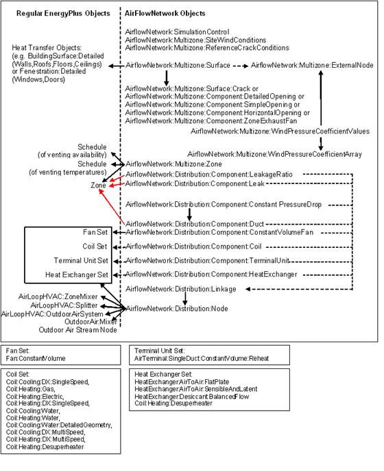
Figure 78. Relationships among AirflowNetwork objects (right-hand side) and between AirflowNetwork objects and regular EnergyPlus objects. An arrow from object A to object B means that A references B.
Much of the information needed for the air flow calculation is automatically extracted from the building description for thermal modeling. This includes things like the volume and neutral height of the zones, and the orientation and location of the building surfaces that contain cracks or openings through which air flows. From all of this information the program creates a “pressure-flow network” that is solved each timestep using iterative solution methods to obtain the unknown pressures and air flows.
Figure 79 shows a plan view of a very simple air flow network that you can construct using the above AirflowNetwork objects. There are three thermal zones, Zone-1, Zone-2 and Zone-3. There are openable exterior windows—Window-1, Window-2 and Window-3—and openable interior doors—Door-12 and Door-23. Two External Nodes are indicated. ExternalNode-1 is associated with the façade that contains Window-1 and Window-2. ExternalNode-2 is associated with the façade containing Window-3.
One possible air flow pattern is shown in this figure. The actual air flow pattern in a particular timestep, and the size of the flows, depends on many factors, such as (1) What is the wind pressure distribution seen by the exterior windows? (2) Are the exterior windows open or closed, and if open, how far are they open? (3) Are the interior doors open or closed? (4) What are the air temperature differences between zones and between zones and the outdoor air (which affect buoyancy flows)?
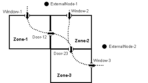
Figure 79. Plan view of a simple air flow network showing a possible air flow pattern in which all of the windows and doors are open.
Figure 79 shows a possible air flow pattern in which all of the windows and doors are open. Associated with the external nodes are wind pressure coefficient distributions as a function of wind direction that are input using two AirflowNetwork:Multizone:Wind Pressure Coefficient objects. The nature of the air flows through the windows and doors is specified using AirflowNetwork:MultiZone:Component:DetailedOpening and AirflowNetwork:MultiZone:Component:SimpleOpening objects. The Airflow Network model calculates the flows each system timestep depending on various factors, including wind direction and speed, size and vertical position of openings, outdoor air temperature, and zone air temperatures.
AirflowNetwork3zVent.idf
AirflowNetwork3zVentAutoWPC.idf
AirflowNetwork_Simple_House.idf
AirflowNetwork_Simple_SmallOffice.idf
AirflowNetwork_Multizone_House.idf
AirflowNetwork_Multizone_House_TwoSpeed.idf
AirflowNetwork_Multizone_SmallOffice.idf
AirflowNetwork_Multizone_SmallOffice_CoilHXAssistedDX.idf
AirflowNetwork_Multizone_SmallOffice_HeatRecoveryHXSL.idf
AirflowNetwor_Multizone_HorizontalOpening.idf
CrossVent_1Zone_AirflowNetwork.idf
DisplacementVent_Nat_AirflowNetwork.idf
HybridVentilationControl.idf
Here is a list of some of the things that the Airflow Network calculation can and cannot model.
1) Air flow through cracks in exterior or interzone surfaces.
2) Air flow through cracks around windows and doors when closed.
3) Natural ventilation (i.e., air flow through open or partially open exterior windows and doors).
4) Zone level control of natural ventilation (all windows/doors in a zone that are defined with a component opening object have identical controls).
5) Individual surface control of natural ventilation for a subsurface (window, door, or glassdoor).
6) Modulation of natural ventilation to prevent large zone air temperature swings.
7) Interzone air flow (i.e., air flow through open interzone windows and doors, and through cracks in interzone surfaces).
8) Dependence of air flow on buoyancy effects and wind pressure.
9) Dependence of wind pressure on wind speed, wind direction and surface orientation.
10)Supply and return air leaks in an air distribution system.
11)Account for the effect of supply-air and/or return-air leakage on zone pressure when a forced air distribution system is present and is operating.
12)When duct leakage is modeled and the HVAC system is on, interzone airflow or infiltration/exfiltration can occur due to changes in zone pressure.
13)Bi-directional flow through large openings. See discussion below under AirflowNetwork:MultiZone:Component:DetailedOpening, AirflowNetwork:Multizone:Component:HorizontalOpening, and AirflowNetwork:Multizone:Component:SimpleOpening.
14)Calculate air flows and pressures in ducts or other components of a forced air distribution system.
15)Calculate zone loads when the supply air fan cycles on and off during a system timestep using the CyclingFanAndCompressor fan operation mode (Fan:OnOff).
16)Determine the impact of zone exhaust fans on air flows, pressures, air temperatures/humidity levels and energy consumption.
1) The model is restricted to using a constant volume fan (Fan:ConstantVolume and Fan:OnOff) and cannot model variable volume fan equipment.
2) Air circulation and/or air temperature stratification within a thermal zone. For example, you should not try to divide a high space, such as an atrium, into subzones separated by artificial horizontal surfaces that have cracks or openings with the expectation that AirflowNetwork will give you a realistic temperature in each subzone and/or a realistic air flow between subzones.
3) The model is restricted to eleven types of coils that can be in the air distribution system (Coil:Cooling:DX:SingleSpeed, Coil:Heating:Gas, Coil:Heating:Electric, Coil:Heating:DX:SingleSpeed, Coil:Cooling:Water, Coil:Heating:Water, Coil:Cooling:Water:DetailedGeometry, Coil:Cooling:DX:TwoStageWithHumidityControlMode, Coil:Cooling:DX:MultiSpeed, Coil:Heating:DX:MultiSpeed, and Coil:Heating:Desuperheater).
4) The model is restricted to a single type of air distribution equipment terminal units (AirTerminal:SingleDuct:ConstantVolume:Reheat).
5) Pollutant transport cannot currently be modeled.
6) Supply and return leaks are not allowed in an AirLoopHVAC. They can only be modeled in the Zone Equipment portion of the air loop (i.e., return leaks may be modeled between the zone return node and the zone mixer inlet or the zone mixer outlet and the zone equipment loop outlet; and supply leaks may be modeled between the zone equipment loop inlet and the AirLoopHVAC:ZoneSplitter inlet node or the AirLoopHVAC:ZoneSplitter outlet node and the zone supply node).
7) An air distribution system must be located inside the building (i.e., the ducts must pass through zones within the building).
8) Zone exhaust fans must be defined in ZoneHVAC:EquipmentConnections objects.
The input specifications consist of five main sections: AirflowNetwork:SimulationControl object, AirflowNetwork multizone data objects, AirflowNetwork distribution node objects, AirflowNetwork distribution component objects, andAirflowNetwork distribution linkage objects. Each of these object types is described in detail below.
The basic run parameters for this model are defined in this unique object which has the following input specifications:
This is a unique character string associated with this instance of the AirflowNetwork:SimulationControl object. At this time, only one AirflowNetwork:SimulationControl object can be specified in an input data file (idf).
The following selections are available to control the Airflow Network simulation:
MultizoneWithDistribution: Multizone air flow calculations are performed during all simulation timesteps, including the impacts of the air distribution system when a HVAC system fan is operating. Any ZoneInfiltration:*, ZoneVentilation:*, ZoneMixing and ZoneCrossMixing objects specified in the input data file are not simulated.
MultizoneWithoutDistribution: Multizone air flow calculations are performed during all simulation timesteps, but the air distribution system portion of the network is not modeled even if it is specified in the input data file. Any ZoneInfiltration:*, ZoneVentilation:*, ZoneMixing and ZoneCrossMixing objects specified in the input data file are not simulated.
MultizoneWithDistributionOnlyDuringFanOperation: Multizone air flow calculations, including the impacts of the air distribution system, are only performed when the HVAC system fan is operating. Any ZoneInfiltration:*, ZoneVentilation:*, ZoneMixing and ZoneCrossMixing objects specified in the input data file are used when the HVAC system fan is OFF (if none are specified, then no air flow calculations are performed when the fan is OFF).
NoMultizoneOrDistribution: No multizone air flow calculations (with or without the air distribution system portion of the network) are performed during the simulation. Any ZoneInfiltration:*, ZoneVentilation:*, ZoneMixing and ZoneCrossMixing objects specified in the input data file are simulated (if none are specified, then no air flow calculations are performed). Note: Having an input data file with no AirflowNetwork:SimulationControl objects gives the same impact – no multizone air flow calculations. However, this choice is provided as a convenience to the user to easily disable the multizone air flow calculations for an input data file that already contains AirflowNetwork objects.
Note: A ZoneInfiltration:* object indicates any one of ZoneInfiltration:DesignFlowRate, ZoneInfiltration:EffectiveLeakageArea,and ZoneInfiltration:FlowCoefficient objects. A object of ZoneVentilation:* indicates any one of ZoneVentilation:DesignFlowRate and ZoneVentilation:WindandStackOpenArea objects.
Determines whether the wind pressure coefficients are input by the user or calculated. The choices are Input or SurfaceAverageCalculation, with the default being SurfaceAverageCalculation.
If INPUT, you must enter an AirflowNetwork:MultiZone:WindPressureCoefficientArray object, one or more AirflowNetwork:MultiZone:ExternalNode objects, and one or more AirflowNetwork:MultiZone:WindPressureCoefficientValues objects.
The second choice, SurfaceAverageCalculation, should only be used for rectangular buildings. In this case surface-average wind pressure coefficients vs. wind direction are calculated by the program for the four vertical facades and the roof based on user entries for “Building Type,” “Azimuth Angle of Long Axis of Building,” and “Ratio of Building Width Along Short Axis to Width Along Long Axis” (see description of these fields below). With this choice you do not have to enter any of the following objects: AirflowNetwork:MultiZone: Wind Pressure Coefficient Array, AirflowNetwork:MultiZone:ExternalNode and AirflowNetwork:MultiZone:WindPressureCoefficientValues.
This is the name of the AirflowNetwork:MultiZone:WindPressureCoefficientArray object that contains wind directions corresponding to the wind pressure coefficients given in the AirflowNetwork:MultiZone:WindPressureCoefficientValues objects.
A value need be entered only if Wind Pressure Coefficient Type = INPUT (see description of previous field).
Determines whether the local wind speed is calculated based on either given external node heights or surface opening heights. The choices are ExternalNode or OpeningHeight, with the default being OpeningHeight. The local outdoor wind speed calculation procedure is given in the section of “Local Wind Speed Calculation” in the Engineering Reference. The calculation procedure requires the height input.
If ExternalNode, the heights given in the AirflowNetwork:MultiZone:ExternalNode objects are used to calculate local wind speeds. Used only if Wind Pressure Coefficient Type = INPUT (see description of previous field).
If OpeningHeight, the number of the AirflowNetwork:MultiZone:ExternalNode objects has to be equal to the number of external surfaces defined in the AirflowNetwork:MultiZone:Surface objects. The centroids in the z direction of the AirflowNetwork:MultiZone:Surface objects are the heights used in the local wind speed calculation. The input is required if Wind Pressure Coefficient Type = INPUT (see description of previous field).
If Wind Pressure Coefficient Type = SurfaceAverageCalculation, a value in this field is not required and a blank may be entered. The default choice is used internally to generate the AirflowNetwork:MultiZone:ExternalNode objects
Used only if Wind Pressure Coefficient Type = SurfaceAverageCalculation. The choices for Building Type are LowRise and HighRise, with the default being LowRise.
LowRise corresponds to a rectangular building whose height is less than three times the width of the footprint (wshort in Figure 80) and is less than three times the length of the footprint (wlong in the same figure).
HighRise corresponds to a rectangular building whose height is more than three times the width of the footprint (wshort in Figure 80) or is more than three times the length of the footprint (wlong in the same figure).
The maximum number of iterations allowed in finding an AirflowNetwork solution. If the number of iterations at each simulation timestep is above the maximum number of iterations defined by this field, the program could not find the solution and a Severe error is issued and the program is aborted. The default value is 500.
Designates which method is used for AirflowNetwork initialization. The choices for Initialization Type are LinearInitializationMethod and ZeroNodePressures, with the default being ZeroNodePressures.
The solution is assumed to have converged when ![]() is less than the value specified for this input field. This convergence criteria is equivalent to the ratio of the absolute value of the sum of all network airflows (
is less than the value specified for this input field. This convergence criteria is equivalent to the ratio of the absolute value of the sum of all network airflows (![]() ) to the sum of network airflow magnitudes (
) to the sum of network airflow magnitudes (![]() ). The default value is 1.0x10⁻⁴.
). The default value is 1.0x10⁻⁴.
The solution is assumed to have converged when the summation of the absolute value of all network airflows (![]() ) is less than the value specified for this input field. The default value is 1.0x10⁻⁶.
) is less than the value specified for this input field. The default value is 1.0x10⁻⁶.
If the ratio of successive pressure corrections is less than this limit, use Steffensen acceleration algorithm (Ref. AirflowNetwork Model in the EnergyPlus Engineering Reference). The range for this field is -1 to 1, with the default value being -0.5.
Gives the orientation of a rectangular building for calculating wind pressure coefficients. This is the smaller of the angles, measured clockwise, between North and the long axis of the building (see Figure 80). Used only if Wind Pressure Coefficient Type = SurfaceAverageCalculation. The range for this input is 0 to 180, with the default value being 0.
This is the aspect ratio of a rectangular footprint. It is given by the width of the footprint along its short axis divided by the width along the long axis (see Figure 80). If the footprint is square, the value of this field is 1.0. Used only if Wind Pressure Coefficient Type = SurfaceAverageCalculation. The range for this input is > 0 to 1, with the default value being 1.
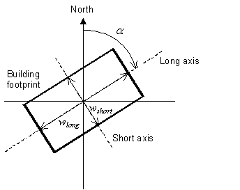
Figure 80. Footprint of a rectangular building showing variables used by the program to calculate surface-average wind pressure coefficients. The angle a is the “Azimuth Angle of Long Axis of Building.” wshort/wlong is the “Ratio of Building Width Along Short Axis to Width Along Long Axis.”
An IDF example is shown below:
AirflowNetwork:SimulationControl,
AirflowNetwork_All, !- Name
MultiZoneWithDistribution, !- AirflowNetwork Control
Input, !- Wind Pressure Coefficient Type
Every 30 Degrees, !- AirflowNetwork Wind Pressure Coefficient Array Name
OpeningHeight, !- Height Selection for Local Wind Speed Calculation
LowRise, !- Building Type
500, !- Maximum Number of Iterations {dimensionless}
ZeroNodePressures, !- Initialization Type
1.0E-05, !- Relative Airflow Convergence Tolerance {dimensionless}
1.0E-06, !- Absolute Airflow Convergence Tolerance {kg/s}
-0.5, !- Convergence Acceleration Limit {dimensionless}
0.0, !- Azimuth Angle of Long Axis of Building {deg}
1.0; !- Ratio of Building Width Along Short Axis to Width Along Long Axis
AirflowNetwork:Multizone data objects are used to calculate multizone airflows. This section describes the input requirements for the following objects:
· AirflowNetwork:MultiZone:Zone
AirflowNetwork:Multizone data objects are used to calculate multizone airflows. This section describes the input requirements for the following objects:
· AirflowNetwork:MultiZone:Zone
· AirflowNetwork:MultiZone:Surface
· AirflowNetwork:MultiZone:Surface:Crack
· AirflowNetwork:MultiZone:ReferenceCrackConditions
· AirflowNetwork:MultiZone:Surface:EffectiveLeakageArea
· AirflowNetwork:MultiZone:Component:DetailedOpening
· AirflowNetwork:MultiZone:Component:SimpleOpening
· AirflowNetwork:MultiZone:Component:HorizontalOpening
· AirflowNetwork:MultiZone:Component:ZoneExhaustFan
· AirflowNetwork:MultiZone:ExternalNode
· AirflowNetwork:MultiZone:WindPressureCoefficientArray
· AirflowNetwork:MultiZone:WindPressureCoefficientValues
A detailed description for each of these objects is provided below.
This object allows control of natural ventilation through exterior and interior openings in a zone, where “opening” is defined as an openable window or door. (Note that only window, door or glass door subsurfaces in a zone that are specified using AirflowNetwork:MultiZone:Component:DetailedOpening, AirflowNetwork:MultiZone:Component:HorizontalOpening or AirflowNetwork:Multizone:Component:SimpleOpening and have an associated AirflowNetwork:Multizone:Surface object are considered to be openings). The control will be applied in the same way to all of the openings in the zone.
This object is required to perform Airflow Network calculations. Note that ventilation control for all openings is provided at the zone level as default and individual ventilation control of a surface opening can be used to override the zone-level control (see the AirflowNetwork:Multizone:Surface object description below).
The name of the EnergyPlus thermal zone corresponding to the AirflowNetwork zone.
Specifies the type of zone-level natural ventilation control.
Let Tout equal the outdoor air temperature, Tzone equal the previous timestep’s zone air temperature, Tset equal the Vent Temperature Schedule value, Hzone equal the specific enthalpy of zone air from the previous timestep, and Hout equal the specific enthalpy of outdoor air. Then the four allowed choices for Ventilation Control Mode are:
NoVent: All of the zone’s openable windows and doors are closed at all times independent of indoor or outdoor conditions. The Venting Availability Schedule is ignored in this case. This is the default value for this field.
Temperature: All of the zone’s openable windows and doors are opened if Tzone > Tout and Tzone > Tset and Venting Availability Schedule (see below) allows venting.
Enthalpy: All of the zone’s openable windows and doors are opened if Hzone > Hout and Tzone > Tset and Venting Availability Schedule allows venting.
Constant: Whenever this object’s Venting Availability Schedule allows venting, all of the zone’s openable windows and doors are open, independent of indoor or outdoor conditions. Note that “Constant” here means that the size of each opening is fixed while venting; the air flow through each opening can, of course, vary from timestep to timestep.
ASHRAE55AdaptiveComfort: All of the zone’s operable windows and doors are opened if the operative temperature is greater than the comfort temperature (central line) calculated from the ASHRAE Standard 55-2010 adaptive comfort model andVenting Availability Schedule allows venting.
CEN15251AdaptiveComfort: All of the zone’s operable windows and doors are opened if the operative temperature is greater than the comfort temperature (central line) calculated from the CEN15251 adaptive comfort model andVenting Availability Schedule allows venting.
The name of a schedule of zone air temperature set points that controls the opening of windows and doors in the thermal zone to provide natural ventilation. This setpoint is the temperature above which all the openable windows and doors in the zone will be opened if the conditions described in the previous field Ventilation Control Mode are met.
The Ventilation Control Zone Temperature Setpoint Schedule Name applies only to windows and doors in the zone that are specified using AirflowNetwork:MultiZone:Component:DetailedOpening, AirflowNetwork:MultiZone:Component:HorizontalOpening or AirflowNetwork:MultiZone:Component:SimpleOpening and have an associated AirflowNetwork:MultiZone:Surface object.
(The discussion under the field Window/Door Opening Factor in the AirflowNetwork:MultiZone:Surface object describes how the actual opening area of a window or door in a particular timestep is determined.)
Modulation of Openings
The following five fields can be used to modulate the window/door openings when Ventilation Control Mode = Temperature or Enthalpy. These fields determine a factor between 0 and 1 that multiplies the opening factor of each window and door in the zone according to the control action shown in Figure 81 for Ventilation Control Mode = Temperature and in Figure 82 for Ventilation Control Mode = Enthalpy. Modulation of the openings can reduce the large temperature swings that can occur if the windows/doors are open too far when they are venting, especially when there is a large inside-outside temperature difference.
The modulation takes the following form when Ventilation Control Mode = Temperature:
Tzone - Tout „ [Lower Value on Inside/Outside Temperature Difference for Modulating the Venting Open Factor] è Multiplication factor = 1.0
[Lower Value on Inside/Outside Temperature Difference for Modulating the Venting Open Factor] < Tzone - Tout < [Upper Value on Inside/Outside Temperature Difference for Modulating the Venting Open Factor] è Multiplication factor varies linearly from 1.0 to [Limit Value on Multiplier for Modulating Venting Open Factor]
Tzone - Tout … [Upper Value on Inside/Outside Temperature Difference for Modulating the Venting Open Factor] è Multiplication factor = [Limit Value on Multiplier for Modulating Venting Open Factor]
One way of “tuning” the following modulation control parameters is to perform a sensitivity analysis for winter and/or summer design days to determine what combination of values causes the biggest reduction in zone air temperature fluctuations due to venting.
Note that the default values for the following fields are such that, if none of the fields are specified, the default values are assigned.
See Figure 81 or Figure 82. This field applies only if Ventilation Control Mode = Temperature or Enthalpy. This value may be from zero to 1.0, with the default being 0.0.
See Figure 81. This field applies only if Ventilation Control Mode = Temperature. This value may be from zero to less than 100˚C, with the default being 0˚C. The value for this field must be less than the value specified for the following field.
See Figure 81. This field applies only if Ventilation Control Mode = Temperature. This value must be greater than 0˚C, with the default being 100˚C. The value for this field must be greater than the value specified for the previous field..
See Figure 82. This field applies only if Ventilation Control Mode = Enthalpy. This value may be from zero to less than 300,000 J/kg, with the default being 0 J/kg. The value for this field must be less than the value specified for the following field.
See Figure 82. This field applies only if Ventilation Control Mode = Enthalpy. This value must be greater than zero, with the default being 300,000 J/kg. The value for this field must be greater than the value specified for the previous field.
The name of a schedule that specifies when venting is available. A zero or negative schedule value means venting is not allowed. A value greater than zero means venting can occur if other venting control conditions (specified by Ventilation Control Mode and Vent Temperature Schedule Name) are satisfied. This schedule name should not be confused with Vent Temperature Schedule Name.
If a Venting Availability Schedule Name is not specified, it is assumed that venting is always available.
Using Venting Availability Schedule allows you to turn off venting at certain times of the day (at night, for example), of the week (on weekends, for example), or of the year (during the winter, for example).
If used with Ventilation Control Mode = Constant, the ventilation rate is constant only when this schedule allows venting; otherwise the ventilation rate is set to zero.
If Ventilation Control Mode = NoVent, this schedule has no effect.
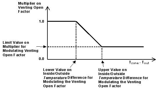
Figure 81. Modulation of venting area according to inside-outside temperature difference.
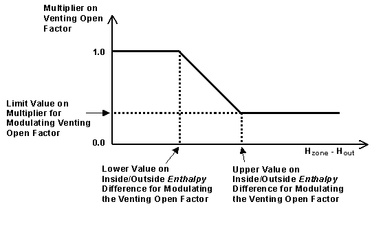
Figure 82. Modulation of venting area according to inside-outside enthalpy difference.
Note: In order to establish an airflow network, each AirflowNetwork:Multizone:Zone object must have at least two surfaces defined with AirflowNetwork:Multizone:Surface objects, so that air can flow from one zone into other zones (or to outdoors) through the network (air mass flow conserved). In addition, for all AirflowNetwork:Multizone:Surface objects facing the same Zone (ref. BuildingSurface:Detailed), at least two different environments must be defined for the other side of these surfaces (e.g., an external node and an adjacent zone, two adjacent zones, or two external nodes).
An IDF example is shown below:
AirflowNetwork:MultiZone:Zone,
RESISTIVE ZONE, !- Name of Associated Thermal Zone
Temperature, !- Ventilation Control Mode
WindowVentSched, !- Vent Temperature Schedule Name
0.3, !- Limit Value on Multiplier for Modulating Venting Open Factor
!- {dimensionless}
5.0, !- Lower Value on Inside/Outside Temperature Difference for
!- Modulating the Venting Open Factor {deltaC}
10.0, !- Upper Value on Inside/Outside Temperature Difference for
!- Modulating the Venting Open Factor {deltaC}
0.0, !- Lower Value on Inside/Outside Enthalpy Difference for Modulating
!- the Venting Open Factor {J/kg}
300000.0, !- Upper Value on Inside/Outside Enthalpy Difference for Modulating
!- the Venting Open Factor {J/kg}
VentingSched; !- Venting Availability Schedule Name
The AirflowNetwork:Multizone:Surface object specifies the properties of a surface “linkage” through which air flows. This linkage is always associated with a heat transfer surface (wall, roof, floor, or a ceiling) or subsurface (door, glass door, or window) with both faces exposed to air. The linkage specifies two connected nodes: two zone nodes defined in AirflowNetwork:Multizone:Zone objects based on inside and outside face environment for an interior surface, or a zone node defined in an AirflowNetwork:Multizone:Zone object based on inside face environment and an external node defined in an AirflowNetwork:MultiZone:ExternalNode object for an exterior surface. The associated leakage component for this surface can be a crack (or surface effective leakage area) in an exterior or interior heat transfer surface or subsurface, or an exterior or interior window, door or glass door (heat transfer subsurface) that can be opened to allow air flow. The allowed surface air leakage components are:
· AirflowNetwork:MultiZone:Surface:Crack
· AirflowNetwork:MultiZone:Surface:EffectiveLeakageArea
· AirflowNetwork:MultiZone:Component:DetailedOpening
· AirflowNetwork:MultiZone:Component:HorizontalOpening
· AirflowNetwork:MultiZone:Component:SimpleOpening
· AirflowNetwork:MultiZone:Component:ZoneExhaustFan
The two “opening” components are used to modulate openness based on required conditions.
The AirflowNetwork:Multizone:Surface object allows a heat transfer surface or subsurface to have one crack (or one surface effective leakage area object), or a subsurface (i.e., window, door or glass door) to have one opening (detailed or simple).
An interior heat transfer surface (BuildingSurface:Detailed) whose surface name is used as the input for the Outside Boundary Condition Object field represents a floor without ground contact and is not allowed as an AirflowNetwork:Multizone:Surface. A heat transfer surface defined in the BuildingSurface:Detailed:ExteriorNaturalVentedCavity is also not allowed.
This is the name of the corresponding surface (wall, roof, ceiling, floor, window, door or glass door).
Information on this surface is used by the program as follows:
(1) For a linkage associated with an exterior heat transfer surface: air flow through this linkage is between the outside environment and the thermal zone to which the surface belongs.
(2) For a linkage associated with an interior (i.e., interzone) heat transfer surface: air flow through this linkage is between the thermal zones separated by the surface (i.e., the thermal zone associated with the inside face environment and the thermal zone associated with the outside face environment).
(3) This heat transfer surface determines the height of the linkage, which is used in calculating buoyancy-related flow through the linkage.
Note: It is possible to define an interzone surface twice in EnergyPlus, once in each of the zones that the surface separates. Previously this was a requirement of EnergyPlus (prior to version 2.0), but now it is optional and the user also has the option of only defining the surface once (EnergyPlus defines the second surface automatically within the program). For each interzone surface, use only one (of possible two) interzone surface names in the AirflowNetwork:Multizone:Surface object for “Surface Name.” Do not enter two AirflowNetwork:Multizone:Surface objects corresponding to the two possible interzone names. This would cause the air flow through the surface to be counted twice.
The name of the AirflowNetwork:MultiZone:Surface:Crack,
AirflowNetwork:MultiZone:Surface:EffectiveLeakageArea,
AirflowNetwork:MultiZone:Component:SimpleOpening,
AirflowNetwork:MultiZone:Component:HorizontalOpening,
AirflowNetwork:MultiZone:Component:DetailedOpening
or AirflowNetwork:MultiZone:Component:ZoneExhaustFan object associated with this air flow linkage.
If the name of an opening component (i.e. AirflowNetwork:MultiZone:Component:DetailedOpening. AirflowNetwork:MultiZone:Component:HorizontalOpening, or AirflowNetwork:MultiZone:Component:SimpleOpening is given here, then the Surface Name in the previous field must be that of a window, door or glass door heat transfer subsurface. Otherwise an error message will be reported.
If the name of an AirflowNetwork:MultiZone:Surface:Crack object or AirflowNetwork:MultiZone:Surface:EffectiveLeakageArea object is given here, the program will position the crack at the average height of the associated heat transfer surface or subsurface. The user can define multiple heat transfer surfaces (e.g., split a wall into several surfaces) to be more precise in establishing the crack location. Similarly, the user can define multiple heat transfer surfaces if a wall, for example, has multiple cracks or openings that need to be defined individually.
If the name of an AirflowNetwork:MultiZone:Component:ZoneExhaustFan is given here, then the Surface Name in the previous field must be that of an exterior heat transfer surface. The zone name defined in the Zone Name field for this heat transfer surface must be the same zone name defined in the ZoneHVAC:EquipmentConnections object (which references a ZoneHVAC:EquipmentList containing the name of the corresponding zone exhaust fan). Otherwise an error message will be reported. When this zone exhaust fan is operating for a simulation timestep, all surface-level controls described below are ignored for that timestep.
The name of the associated AirflowNetwork:MultiZone:ExternalNode object, which determines the wind pressure coefficients for the heat transfer surface. Used only if Surface Name is for an exterior surface.
If Wind Pressure Coefficient Type = SurfaceAverageCalculation in the AirflowNetwork:SimulationControl object, this field is not used and a blank may be entered. If the surface is an interior (i.e., interzone) surface, leave this field blank.
If this linkage is associated with an AirflowNetwork:MultiZone:Component:DetailedOpening or AirflowNetwork:MultiZone:Component:SimpleOpening object (which means it is an openable window or door), then this field is called “Window/Door Opening Factor” and represents the value of the Opening Factor that is in effect when the Vent Temperature Schedule (defined in the AirflowNetwork:Multizone:Zone object) indicates that this window or door is open.
The AirflowNetwork model uses a combination of factors to determine the actual opening area for a window or door when it is venting. For example, consider a window that is 1.5m high and 2.0m wide (excluding frame). Assume that the AirflowNetwork:MultiZone:Component:DetailedOpening for this window has Type of Large Vertical Opening = 1 (non-pivoting window), Height Factor = 0.5 and Width Factor = 0.8. Then when the window is fully open, the opening area = height of opening (0.5x1.5) times width of opening (0.8x2.0) = 0.75x1.6 = 1.2 m2. If the Window/Door Opening Factor is 0.75, then the opening area = 0.75x1.2 = 0.9 m2.
If, in addition, the window is in a thermal zone for which opening modulation has been specified (ref: AirflowNetwork:Multizone:Zone) and the multiplication factor due to modulation is 0.3 in a particular timestep, then the actual opening factor that timestep = 0.3x0.75 = 0.225 and the actual opening area that timestep = 0.3x0.9 = 0.27 m2.
If this linkage is associated with an AirflowNetwork:MultiZone:Surface:Crack object, the following crack air flow equation is used.
![]()
Where
Q = air mass flow (kg/s)
CQ = air mass flow coefficient (kg/s @ 1 Pa)
CT = reference condition temperature correction factor (dimensionless). See AirflowNetwork:MultiZone:Surface:Crack object.
![]() = pressure difference across crack (Pa)
= pressure difference across crack (Pa)
n = air flow exponent (dimensionless)
The following fields control venting. They are used only when Name of Associated Heat Transfer Surface is that of an openable exterior or interior window, door or glass door. They only apply to openings, and do not apply to surface cracks, effective leakage area or zone exhaust fans. If none of these fields is specified, or if Ventilation Control Mode = ZoneLevel, venting is controlled by the AirflowNetwork:Multizone:Zone object for the thermal zone containing the window or door (ref: AirflowNetwork:Multizone:Zone Data).
Specifies the type of surface-level natural ventilation control.
Let Tout equal the outdoor air temperature, Tzone equal the previous timestep’s zone air temperature, Tset equal the Vent Temperature Schedule value, Hzone equal the specific enthalpy of zone air from the previous timestep, and Hout equal the specific enthalpy of outdoor air. Then the four allowed choices for Ventilation Control Mode are:
NoVent: The openable window or door associated with this surface is closed at all times independent of indoor or outdoor conditions. The Venting Availability Schedule is ignored in this case.
Temperature: The openable window or door associated with this surface is opened if Tzone > Tout and Tzone > Tset and Venting Availability Schedule (see below) allows venting.
Enthalpy: The openable window or door associated with this surface is opened if Hzone > Hout and Tzone > Tset and Venting Availability Schedule allows venting.
Constant: Whenever this object’s Venting Availability Schedule allows venting, the openable window or door associated with this surface is open, independent of indoor or outdoor conditions. Note that “Constant” here means that the size of this opening is fixed while venting; the air flow through this opening can, of course, vary from timestep to timestep.
ASHRAE55AdaptiveComfort: The openable window or door associated with this surface is opened if the operative temperature is greater than the comfort temperature (central line) calculated from the ASHRAE Standard 55-2010 adaptive comfort model and Venting Availability Schedule allows venting.
CEN15251AdaptiveComfort: The openable window or door associated with this surface is opened if the operative temperature is greater than the comfort temperature (central line) calculated from the CEN15251 adaptive comfort model and Venting Availability Schedule allows venting.
ZoneLevel: Venting of the window or door is not controlled individually, but is controlled instead at the zone level. This means that the venting is determined by the AirflowNetwork:Multizone:Zone object for the thermal zone containing the window or door (ref: AirflowNetwork:Multizone:Zone object). This is the default value for this field.
AdjacentTemperature: This choice is used for an interior surface only. The openable interior window or door associated with this surface is opened if Tzone > Tadjacent zone and Tzone > Tset and Venting Availability Schedule (see below) allows venting, where Tadjacent zone is the adjacent zone temperature.
AdjacentEnthalpy: This choice is also used for an interior surface only. The interior openable window or door associated with this surface is opened if Hzone > Hadjacent zone and Tzone > Tset and Venting Availability Schedule allows venting, where Hadjacent zone is the adjacent zone specific enthalpy.
The name of a schedule of zone air temperature set points that controls the opening of a window or door associated with this surface to provide natural ventilation. This setpoint is the temperature above which this openable window or door will be opened if the conditions described in the previous field Ventilation Control Mode are met.
The Ventilation Control Zone Temperature Setpoint Schedule applies only to a window or door attached to this surface that is specified using AirflowNetwork:MultiZone:Component:DetailedOpening or AirflowNetwork:MultiZone:Component:SimpleOpening.
(The discussion under the field Window/Door Opening Factor in this object describes how the actual opening area of a window or door in a particular timestep is determined.)
Modulation of Openings
The following five fields can be used to modulate this window/door opening when Ventilation Control Mode = Temperature or Enthalpy. These fields determine a factor between 0 and 1 that multiplies the opening factor of this window or door according to the control action shown in Figure 81 for Ventilation Control Mode = Temperature and in Figure 82 for Ventilation Control Mode = Enthalpy. Modulation of this opening can reduce the large temperature swings that can occur if the window/door is open too far when it is venting, especially when there is a large inside-outside temperature difference.
The modulation takes the following form when Ventilation Control Mode = Temperature:
Tzone - Tout „ [Lower Value on Inside/Outside Temperature Difference for Modulating the Venting Open Factor] è Multiplication factor = 1.0
[Lower Value on Inside/Outside Temperature Difference for Modulating the Venting Open Factor] < Tzone - Tout < [Upper Value on Inside/Outside Temperature Difference for Modulating the Venting Open Factor] è Multiplication factor varies linearly from 1.0 to [Limit Value on Multiplier for Modulating Venting Open Factor]
Tzone - Tout … [Upper Value on Inside/Outside Temperature Difference for Modulating the Venting Open Factor] è Multiplication factor = [Limit Value on Multiplier for Modulating Venting Open Factor]
One way of “tuning” the following modulation control parameters is to perform a sensitivity analysis for winter and/or summer design days to determine what combination of values causes the biggest reduction in zone air temperature fluctuations due to venting.
Note that the default values for the following fields are such that, if none of the fields are specified, modulation will not occur.
See Figure 81 or Figure 82. This field applies only if Ventilation Control Mode = Temperature or Enthalpy. This value may be from zero to 1.0, with the default being 0.0.
See Figure 81. This field applies only if Ventilation Control Mode = Temperature. This value may be from zero to less than 100°C, with the default being 0°C. The value for this field must be less than the value specified for the following field.
See Figure 81. This field applies only if Ventilation Control Mode = Temperature. This value must be greater than 0°C, with the default being 100°C. The value for this field must be greater than the value specified for the previous field.
See Figure 82. This field applies only if Ventilation Control Mode = Enthalpy. This value may be from zero to less than 300,000 J/kg, with the default being 0 J/kg. The value for this field must be less than the value specified for the following field.
See Figure 82. This field applies only if Ventilation Control Mode = Enthalpy. This value must be greater than zero, with the default being 300,000 J/kg. The value for this field must be greater than the value specified for the previous field.
The name of a schedule that specifies when venting is available. A zero or negative schedule value means venting is not allowed. A value greater than zero means venting can occur if other venting control conditions (specified by Ventilation Control Mode and Vent Temperature Schedule Name) are satisfied. This schedule name should not be confused with Vent Temperature Schedule Name.
If a Venting Availability Schedule Name is not specified, it is assumed that venting is always available.
Using Venting Availability Schedule allows you to turn off venting at certain times of the day (at night, for example), week (on weekends, for example), or year (during the winter, for example).
If used with Ventilation Control Mode = Constant, the ventilation rate is constant only when this schedule allows venting; otherwise the ventilation rate is set to zero.
If Ventilation Control Mode = NoVent, this schedule has no effect.
Note: In order to establish an airflow network, each AirflowNetwork:Multizone:Zone object must have at least two surfaces defined with AirflowNetwork:Multizone:Surface objects, so that air can flow from one zone into other zones (or to outdoors) through the network (air mass flow conserved). In addition, for all AirflowNetwork:Multizone:Surface objects facing the same Zone Name (ref. BuildingSurface:Detailed), at least two different environments must be defined for the other side of these surfaces (e.g., an external node and an adjacent zone, two adjacent zones, or two external nodes).
IDF examples are provided below:
AirflowNetwork:MultiZone:Surface,
Zn001:Wall001, !- Name of Associated Heat Transfer Surface
CR-1, !- Leakage Component Name
SFacade, !- External Node Name
1.0; !- Window/Door Opening Factor, or Crack Factor {dimensionless}
AirflowNetwork:MultiZone:Surface,
Zn001:Wall001:Win001, !- Name of Associated Heat Transfer Surface
WiOpen1, !- Leakage Component Name
SFacade, !- External Node Name
0.5; !- Window/Door Opening Factor, or Crack Factor {dimensionless}
AirflowNetwork:MultiZone:Surface,
Zn003:Wall003, !- Name of Associated Heat Transfer Surface
Zone3 Exhaust Fan, !- Leakage Component Name
EFacade, !- External Node Name
1.0; !- Window/Door Opening Factor, or Crack Factor {dimensionless}
AirflowNetwork:MultiZone:Surface,
Zn001:Wall001:Win002, !- Name of Associated Heat Transfer Surface
WiOpen2, !- Leakage Component Name
WFacade, !- External Node Name
0.5; !- Window/Door Opening Factor, or Crack Factor {dimensionless}
Temperature, !- Ventilation Control Mode
WindowVentSched, !- Vent Temperature Schedule Name
0.3, !- Limit Value on Multiplier for Modulating Venting Open Factor
!- {dimensionless}
5.0, !- Lower Value on Inside/Outside Temperature Difference for
!- Modulating the Venting Open Factor {deltaC}
10.0, !- Upper Value on Inside/Outside Temperature Difference for
!- Modulating the Venting Open Factor {deltaC}
0.0, !- Lower Value on Inside/Outside Enthalpy Difference for Modulating
!- the Venting Open Factor {J/kg}
300000.0, !- Upper Value on Inside/Outside Enthalpy Difference for Modulating
!- the Venting Open Factor {J/kg}
VentingSched; !- Venting Availability Schedule Name
This object specifies the reference conditions for temperature, humidity, and pressure which correspond to the AirflowNetwork:MultiZone:Surface:Crack object.
The name of this Reference Crack Conditons object. This name is referenced by an AirflowNetwork:MultiZone:Surface:Crack object.
The reference temperature in °C under which the Surface Crack Data were obtained. The default value is 20°C.
The reference barometric pressure in Pa under which the Surface Crack Data were obtained. The default value is 101325 Pa.
The reference humidity ratio in kg/kg under which the Surface Crack Data were obtained. The default value is 0 kg/kg.
An IDF example is provided below:
AirflowNetwork:MultiZone:ReferenceCrackConditions,
ReferenceCrackConditions, !- Name of Reference Crack Conditions
20.0, !- Reference Temperature for Crack Data {C}
101325, !- Reference Barometric Pressure for Crack Data {Pa}
0.0; !- Reference Humidity Ratio for Crack Data {kg/kg}
This object specifies the properties of air flow through a crack and the associated measurement conditions. The following power law form is used that gives air flow through the crack as a function of the pressure difference across the crack:
![]()
Where
Q = air mass flow (kg/s)
CQ = air mass flow coefficient (kg/s-Pan @ 1 Pa)
CT = reference condition temperature correction factor (dimensionless)
![]() = pressure difference across crack (Pa)
= pressure difference across crack (Pa)
n = air flow exponent (dimensionless)

where
ρ = Air density at the specific air temperature and humidity ratio conditions [kg/m3]
ν = Air kinetic viscosity at the specific air temperature condition [m2/s]
ρo = Air density at the reference air conditions provided by the object AirflowNetwork:MultiZone:ReferenceCrackConditions specified in the field Reference Crack Conditions [kg/m3]
νo = Air kinetic viscosity at the reference air temperature provided by the object AirflowNetwork:MultiZone:ReferenceCrackConditions specified in the field Reference Crack Conditions [m2/s]
Note: The correction factor shown above is use for this particular component as specified.
This is a name for this AirflowNetwork:MultiZone:Surface:Crack object. It is referenced by an AirflowNetwork:Multizone:Surface object.
The value of the air mass flow coefficient,![]() , in the crack air flow equation. It has units of kg/s at 1Pa. This value must be greater than zero.
, in the crack air flow equation. It has units of kg/s at 1Pa. This value must be greater than zero.
The value of the exponent, n, in the crack air flow equation. The valid range is 0.5 to 1.0, with the default value being 0.65.
The name of the AirflowNetwork:MultiZone:ReferenceCrackConditions object which specifies the conditions under which the air mass flow coefficient was measured. If the user omits this field and only one AirflowNetwork:MultiZone:ReferenceCrackConditions object is defined in the input data file, then those reference crack conditions will be used. If the user omits this field and either zero or more than one AirflowNetwork:MultiZone:ReferenceCrackConditions objects are defined in the input data file, then the default conditions for the AirflowNetwork:Multizone: Reference Crack Conditions object will be used.
An IDF example is shown below:
AirflowNetwork:MultiZone:Surface:Crack,
CR-1, !- Name of Surface Crack Component
0.01, !- Air Mass Flow Coefficient at Reference Conditions {kg/s}
0.667, !- Air Mass Flow Exponent {dimensionless}
ReferenceCrackConditions; !- Reference Crack Conditions
The effective leakage area (ELA) object is used to define surface air leakage. It has
five fields. The relationship between pressure and airflow may be expressed as:
![]()
where
![]() = Air mass flow rate [kg/s]
= Air mass flow rate [kg/s]
ELA = Effective leakage area [m2]
ρ = Air density [kg/m3]
![]() = Reference pressure difference [Pa]
= Reference pressure difference [Pa]
![]() = Pressure difference across this component [Pa]
= Pressure difference across this component [Pa]
Cd = Discharge coefficient [dimensionless]
n = Air mass flow exponent [dimensionless]
This is a name for this AirflowNetwork:MultiZone:Surface:EffectiveLeakageArea object. It is referenced by an AirflowNetwork:Multizone:Surface object.
This numeric field is used to input the effective leakage area in square meters. The effective leakage area is used to characterize openings for infiltration calculations (ASHRAE Handbook of Fundamentals, 1997, pp 25.18). This value must be greater than zero.
This numeric field is used to input the discharge coefficient. This value must be greater than zero, with a default value of 1.0.
This numeric field is used to input the reference pressure difference [Pa]. This value must be greater than zero, with a default value of 4.0 Pa.
This numeric field is used to input the pressure difference exponent. The valid range of the exponent is from 0.5 to 1.0, with a default value of 0.65.
Note: There are two common sets of reference conditions: Cd = 1.0 and DP = 4 Pa, or Cd = 0.6 and DP = 10 Pa
An IDF example is shown below:
AirflowNetwork:MultiZone:Surface:EffectiveLeakageArea,
SurfaceELR, !- Name of surface effective leakage area component
0.07, !- Effective leakage area {dimensionless}
1.00, !- Discharge coefficient {dimensionless}
4.0, !- Reference pressure difference {Pa}
0.65; !- Air mass flow exponent {dimensionless}
This object specifies the properties of air flow through windows and doors (window, door and glass door heat transfer subsurfaces) when they are closed or open. The fields are similar to those for AirflowNetwork:Multizone:SurfaceCrack object when the window or door is closed, but additional fields are required to describe the air flow characteristics when the window or door is open. These additional fields include opening type, opening dimensions, degree of opening, and opening schedule.
The AirflowNetwork model assumes that open windows or doors are vertical or close to vertical; for this reason they are called “Large Vertical Openings.” Such openings can have air flow moving simultaneously in two different directions depending on stack effects and wind conditions (for example, flow from inside to outside at the top of a window and from outside to inside at the bottom). AirflowNetwork models such two-directional flow, but only for vertical openings.
It is assumed that the air flow through a window opening is unaffected by the presence of a shading device such as a shade or blind on the window. Also, the calculation of conductive heat transfer and solar gain through a window or door assumes that the window or door is closed.
The AirflowNetwork model does not have a model for bi-directional flow through large horizontal openings. For this reason, AirflowNetwork:MultiZone:Component:DetailedOpening should not be used for horizontal openings. The best modeling technique in this case is to put an AirflowNetwork:MultiZone:Surface:Crack object in a horizontal surface and use a large air mass flow coefficient. Crack flow is assumed to be uni-directional in any given timestep (but can reverse flow direction from timestep to timestep).
A subsurface multiplier may be used to represent multiple subsurfaces and calculates total air flow when the subsurface (window, glassdoor, or door) is either closed or open. The total airflow across the surface is equal to the airflow based on the surface geometry multiplied by the subsurface multiplier.
The name of this AirflowNetwork:MultiZone:Component:DetailedOpening object. It is referenced by an AirflowNetwork:Multizone:Surface object.
Crack flow is assumed when the window or door is closed. The units for this air mass flow coefficient (![]() ) are different from the units for
) are different from the units for ![]() (kg/s at 1 Pa pressure difference) defined in an AirflowNetwork:MultiZone:Surface:Crack object. There is no default but the entered value must be greater than zero. The program will automatically generate four cracks around the perimeter of the window or door--one along the bottom, one along the top, and one on each side. The temperature correction factor used in the AirflowNetwork:MultiZone:Surface:Crack object is not used for this component to calculate air mass flow rate.
(kg/s at 1 Pa pressure difference) defined in an AirflowNetwork:MultiZone:Surface:Crack object. There is no default but the entered value must be greater than zero. The program will automatically generate four cracks around the perimeter of the window or door--one along the bottom, one along the top, and one on each side. The temperature correction factor used in the AirflowNetwork:MultiZone:Surface:Crack object is not used for this component to calculate air mass flow rate.
Crack flow is assumed when the window or door is closed. In this case, the value of this field is the exponent, n, in the crack air flow equation. The valid range for this exponent is 0.5 to 1.0, with the default value being 0.65.
This alpha field specifies the type of rectangular window or door. (Open windows or doors are also called Large Vertical Openings (LVOs). The choices for the opening type are NonPivoted (LVO Type 1) and HorizontallyPivoted (LVO Type 2) with the default being NonPivoted. The NonPivoted type represents a regular window or door. The HorizontallyPivoted type represents a window with a horizontal axis ((i.e., a horizontally-pivoting window) and cannot be used for a door.
Specifies window or door characteristics that depend on the LVO type.
For LVO Type 1 (rectangular non-pivoted windows and doors) this field is the extra crack length in meters due to multiple openable parts, if present. “Extra” here means in addition to the length, calculated by the program, of the cracks on the top, bottom and sides of the window/door.
For LVO Type 2 (rectangular horizontally-pivoted windows) this field gives the height of the pivoting axis measured from the bottom of the glazed part of the window (m).
This is the number of the following sets of data for opening factor, discharge coefficient, width factor, height factor, and start height factor. From two to four of these sets must be defined. The first set should be for Opening Factor = 0.0 and the last set should be for Opening Factor = 1.0. For example, if only two sets are defined, the first set should be for Opening Factor = 0.0 and the second set should be for Opening Factor = 1.0, as shown below in the IDF example below.
An “opening factor” refers to the amount that a window or door is opened. The program linearly interpolates each timestep between the values of discharge coefficient, width factor, etc., in these sets using the opening factor for the window or door for the timestep. (See discussion under the field Window/Door Opening Factor in the AirflowNetwork:Multizone:Zone object for a description of how the AirflowNetwork model determines the time-step value of the opening factor.)
Each field is described for as many groups as required in the previous field (number of sets of opening factor data). As the final field has specific requirements, this field (n) will be described.
The first opening factor of a window or door. This value must be 0.0. The default value is also 0.0.
For LVO Type 1 (rectangular non-pivoted window or door), the Opening Factor corresponds to the fraction of window or door that is opened.
For LVO Type 2 (rectangular horizontally-pivoted windows), the Opening Factor is determined by the window opening angle. For example, an opening angle of 45° corresponds to an Opening Factor of 0.50 since the maximum opening angle is 90°.
The discharge coefficient of the window or door for Opening Factor 1. The range is greater than 0.0 to less than or equal to 1.0. The default value is 0.001. The Discharge Coefficient indicates the fractional effectiveness for air flow through a window or door at that Opening Factor.
Note: In the following, “window width” and “window height” are glazing dimensions; they do not include the frame, if present.
The Width Factor of the rectangular window or door for Opening Factor 1. The Width Factor is the opening width divided by the window or door width (see Figure 83). The range is 0.0 to 1.0. The default value is 0.0. Note that the width factor applies to rectangular windows or doors where the width is assumed constant along the entire height of the opening.
The Height Factor of the rectangular window or door for Opening Factor 1. The Height Factor is the opening height divided by the window or door height (see Figure 83). The range is 0.0 to 1.0. The default value is 0.0. Note that the height factor applies to rectangular windows or doors where the height is assumed constant along the entire width of the opening.
The Start Height Factor of the window or door for Opening Factor 1. The Start Height Factor is the Start Height divided by the window or door height (see Figure 83). The range is 0.0 to 1.0. The default is 0. Start Height is the distance between the bottom of the window or door and the bottom of the window or door opening. The sum of the Height Factor and the Start Height Factor must be less than 1.0 in order to have the opening within the window or door dimensions.
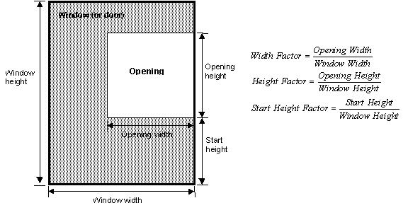
Figure 83. Window (or door) showing geometrical factors associated with an opening through which air flows.
When Number of Sets of Opening Factor Data = n, the value of Opening Factor n must be set to 1.0.
The discharge coefficient of the window or door for Opening Factor n. The range is greater than 0.0 to less than or equal to 1.0. The default value is 1.0.
The Width Factor of the rectangular window or door for Opening Factor n. The Width Factor is the opening width divided by the window or door width (see Figure 83). The range is 0.0 to 1.0. The default value is 1.0.
The Height Factor of the rectangular window or door for Opening Factor n. The Height Factor is the opening height divided by the window or door height (see Figure 83). The range is 0.0 to 1.0. The default value is 1.0.
The Start Height Factor of the window or door for Opening Factor n. The Start Height Factor is the Start Height divided by the window or door height (see Figure 83). The range is 0.0 to 1.0. The default is 0.
When the opening factor value (as described under the field Window/Door Opening Factor in the AirflowNetwork:Multizone:Surface object) is between two Opening Factor field values, the values of Discharge Coefficient, Width Factor, Height Factor, and Start Height Factor are linearly interpolated.
An IDF example is shown below:
AirflowNetwork:MultiZone:Component:DetailedOpening,
WiOpen1, !- Detailed Opening Name
0.001, !- Air Mass Flow Coefficient When Opening is Closed {kg/s-m}
0.667, !- Air Mass Flow Exponent When Opening is Closed {dimensionless}
NonPivoted, !- Type of Large Vertical Opening (LVO)
0.0, !- Extra crack length for LVO type 1 with multiple openable parts,
!- or Height of pivoting axis for LVO type 2 {m}
2, !- Number of Sets of Opening Factor Data
0.0, !- Opening factor 1 {dimensionless}
0.5, !- Discharge coefficient for opening factor 1 {dimensionless}
0.0, !- Width factor for opening factor 1 {dimensionless}
1.0, !- Height factor for opening factor 1 {dimensionless}
0.0, !- Start height factor for opening factor 1 {dimensionless}
1.0, 0.6, 1.0, 1.0, 0.0; !- Set of values for opening factor 2
This object specifies the properties of air flow through windows, doors and glass doors (heat transfer subsurfaces defined as a subset of FenestrationSurface:Detailed objects) when they are closed or open. This AirflowNetwork model assumes that these openings are horizontal or close to horizontal and are interzone surfaces. The second and third input fields are similar to those for AirflowNetwork:MultiZone:Surface:Crack, when the window or door is closed, but additional information is required to describe the air flow characteristics when the window or door is open. This additional information is specified in the last two input fields. The airflow across the opening consists of two types of flows: forced and buoyancy. The forced flow is caused by the pressure difference between two zones, while the buoyancy flow only occurs when the air density in the upper zone is greater than the air density in the lower zone. This opening also allows for the possibility of two-way flow when forced and buoyancy flows co-exist. This object’s openness can also be modulated based on the same opening factor control as an AirflowNetwork:MultiZone:Component:DetailedOpening object. However, the opening factor is only applied to the subsurface width. The opening width is equal to opening factor multiplied by the subsurface width.
A subsurface multiplier may be used to represent multiple subsurfaces and calculates total air flow when the subsurface (window, glassdoor, or door) is either closed or open. The total airflow across the surface is equal to the airflow based on the surface geometry multiplied by the subsurface multiplier.
This is a name for this AirflowNetwork:MultiZone:Component:HorizontalOpening object. It is referenced by an AirflowNetwork:Multizone:Surface object.
The value of the air mass flow coefficient, ![]() , in the horizontal opening air flow equation. It has units of kg/s-m at 1Pa. The temperature correction factor is not applied to the mass flow calculation. This is a required input field and the entered value must be greater than zero.
, in the horizontal opening air flow equation. It has units of kg/s-m at 1Pa. The temperature correction factor is not applied to the mass flow calculation. This is a required input field and the entered value must be greater than zero.
The value of the exponent, n, in the crack air flow equation. The valid range is 0.5 to 1.0, with the default value being 0.65.
This numeric field is used to represent the angle between the horizontal plane and a sloped plane under the horizontal opening. Sloping plane angle = 90 is equivalent to fully open. The valid range is >0 to 90, with the default value being 90.
This numeric field is used to input the discharge coefficient. This is a required field and the entered value must be greater than zero.
An IDF example is shown below:
AirflowNetwork:MultiZone:Component:HorizontalOpening,
HrOpen, !- Name
0.001, !- Air Mass Flow Coefficient When Opening is Closed {kg/s-m}
0.667, !- Air Mass Flow Exponent When Opening is Closed {dimensionless}
90.0, !- Sloping Plane Angle
0.2; !- Discharge Coefficient
This object specifies the properties of air flow through windows, doors and glass doors (heat transfer subsurfaces) when they are closed or open. The AirflowNetwork model assumes that open windows or doors are vertical or close to vertical. The second and third fields are similar to those for AirflowNetwork:MultiZone:Surface:Crack, when the window or door is closed, but additional information is required to describe the air flow characteristics when the window or door is open. This additional information is specified in the last two fields. Compared to the object AirflowNetwork:MultiZone:Component:DetailedOpening, which requires more inputs at different opening factors, this object needs comparatively less inputs. For this reason it is called a simple opening. This opening also allows for the possibility of two-way flow due to temperature and resulting density differences. Therefore, it is possible to have a positive pressure difference at the top of the opening, and a negative pressure difference at the bottom (or vice versa) when the neutral height is between the bottom and top heights of the associated surface. This object’s openness can also be modulated based on the same opening factor control as an AirflowNetwork:MultiZone:Component:DetailedOpening object. However, the opening factor is only applied to the subsurface width. The opening width is equal to opening factor multiplied by the subsurface width.
A subsurface multiplier may be used to represent multiple subsurfaces and calculates total air flow when the subsurface (window, glassdoor, or door) is either closed or open. The total airflow across the surface is equal to the airflow based on the surface geometry multiplied by the subsurface multiplier.
This is a name for this AirflowNetwork:MultiZone:Component:SimpleOpening object. It is referenced by an AirflowNetwork:Multizone:Surface object.
The value of the air mass flow coefficient, ![]() , in the simple opening air flow equation. It has units of kg/s-m at 1Pa. The temperature correction factor is not applied for mass flow calculation.
, in the simple opening air flow equation. It has units of kg/s-m at 1Pa. The temperature correction factor is not applied for mass flow calculation.
The value of the exponent, n, in the crack air flow equation. The valid range is 0.5 to 1.0, with the default value being 0.65.
This numeric field is used to input the minimum density difference above which two-way flow may occur due to stack effect. Density differences less than this value result in one-way flow. The minimum value for this field is greater than zero.
This numeric field is used to input the discharge coefficient. This value must be greater than zero.
An IDF example is shown below:
AirflowNetwork:MultiZone:Component:SimpleOpening,
WiOpen2, !- Simple Opening Name
0.001, !- Air Mass Flow Coefficient When Opening Is Closed {kg/s-m}
0.650, !- Air Mass Flow Exponent When Opening Is Closed {dimensionless}
0.0001, !- Minimum density difference for two-way flow (kg/m3)
1.0; !- Discharge coefficient (dimensionless)
This object specifies the properties of air flow through an exterior heat transfer surface with a zone exhaust fan. The zone exhaust fan turns on or off based on the availability schedule defined in the corresponding Fan:ZoneExhaust object. When the exhaust fan mass flow rate is greater than zero, the airflow network model treats this object as a constant volume fan. When the fan is off based on the availability schedule, the model treats this object as a crack.
When the fan is on, the air mass flow rate modeled for the airflow network is based on the value defined in the Maximum Flow Rate field of the Fan:ZoneExhaust object. The airflow direction is from the corresponding zone to outdoors.
When the fan is off, the following power law form is used that gives air flow through the crack as a function of the pressure difference across the crack:
![]()
Where
Q = air mass flow (kg/s)
CQ = air mass flow coefficient (kg/s-Pan @ 1 Pa)
CT = reference condition temperature correction factor (dimensionless)
![]() = pressure difference across crack (Pa)
= pressure difference across crack (Pa)
n = air flow exponent (dimensionless)
where
ρ = Air density at the specific air temperature and humidity ratio conditions [kg/m3]
ν = Air kinetic viscosity at the specific air temperature condition [m2/s]
ρo = Air density at the reference air conditions provided by the object AirflowNetwork:MultiZone:ReferenceCrackConditions specified in the field Reference Crack Conditions [kg/m3]
νo = Air kinetic viscosity at the reference air temperature provided by the object AirflowNetwork:MultiZone:ReferenceCrackConditions specified in the field Reference Crack Conditions [m2/s]
Note: The correction factor shown above is used when the exhaust fan is off. The airflow direction is based on the pressure difference between the zone and outdoors.
This is the name for this instance of the AirflowNetwork:MultiZone:Component:ZoneExhaustFan object. This name must be the same name defined in the Fan:ZoneExhaust object. It is referenced by an AirflowNetwork:Multizone:Surface object.
The value of the air mass flow coefficient,![]() , in the crack air flow equation. It has units of kg/s at 1Pa. This value must be greater than zero. The value is used when the fan is off.
, in the crack air flow equation. It has units of kg/s at 1Pa. This value must be greater than zero. The value is used when the fan is off.
The value of the exponent, n, in the crack air flow equation. The valid range is 0.5 to 1.0, with the default value being 0.65. The value is used when the fan is off.
The name of the AirflowNetwork:MultiZone:ReferenceCrackConditions object which specifies the conditions under which the air mass flow coefficient was measured. If the user omits this field and only one AirflowNetwork:MultiZone:ReferenceCrackConditions object is defined in the input data file, then those reference crack conditions will be used. If the user omits this field and either zero or more than one AirflowNetwork:MultiZone:ReferenceCrackConditions objects are defined in the input data file, then the default conditions for the AirflowNetwork:Multizone: Reference Crack Conditions object will be used.
An IDF example is shown below:
AirflowNetwork:MultiZone:Component:ZoneExhaustFan,
Zone3 Exhaust Fan, !- Name
0.01, !- Air Mass Flow Coefficient When the Zone Exhaust Fan is Off at Reference Conditions {kg/s}
0.667; !- Air Mass Flow Exponent When the Zone Exhaust Fan is Off{dimensionless}
ReferenceCrackConditions; !- Reference Crack Conditions
External nodes in the AirflowNetwork model define environmental conditions outside of the building. These conditions include wind pressure coefficients that vary from façade to façade and can be highly dependent on the building geometry.
AirflowNetwork:MultiZone:ExternalNode objects do not have to be entered if Wind Pressure Coefficient Type = SurfaceAverageCalculation in the AirflowNetwork:SimulationControl object.
The external node name is associated with a particular building façade. This name is referenced by the External Node Name field of an AirflowNetwork:MultiZone:WindPressureCoefficientValues object (which gives wind pressure coefficients for the façade as a function of angle of wind incident on the façade) and by the External Node Name field of an AirflowNetwork:MultiZone:Surface object.
Designates the reference height, in meters, used to calculate relative pressure. The default value is 0 meters.
The name of a specific AirflowNetwork:MultiZone:WindPressureCoefficientValues object (which gives wind pressure coefficients for the façade as a function of angle of wind incident on the façade).
IDF examples are provided below:
AirflowNetwork:MultiZone:ExternalNode,
NFacade, !- Name
1.524, !- External Node Height {m}
NFacade_WPCValue; !- Wind Pressure Coefficient Values Object Name
AirflowNetwork:MultiZone:ExternalNode,
EFacade, !- Name
1.524, !- External Node Height {m}
EFacade_WPCValue; !- Wind Pressure Coefficient Values Object Name
AirflowNetwork:MultiZone:ExternalNode,
SFacade, !- Name
1.524, !- External Node Height {m}
SFacade_WPCValue; !- Wind Pressure Coefficient Values Object Name
AirflowNetwork:MultiZone:ExternalNode,
WFacade, !- Name
1.524, !- External Node Height {m}
WFacade_WPCValue; !- Wind Pressure Coefficient Values Object Name
AirflowNetwork:MultiZone:ExternalNode,
Horizontal, !- Name
3.028, !- External Node Height {m}
Horizontal_WPCValue; !- Wind Pressure Coefficient Values Object Name
The reference height and wind directions are first specified under the AirflowNetwork:MultiZone:WindPressureCoefficientArray object. The user may specify up to 36 different wind directions in ascending order. These are then referenced by AirflowNetwork:MultiZone:WindPressureCoefficientValues objects defined for each AirflowNetwork:MultiZone:ExternalNode.
The AirflowNetwork:MultiZone:WindPressureCoefficientArray object is unique and needs to be entered only if Wind Pressure Coefficient Type = INPUT in the AirflowNetwork:SimulationControl object. If Wind Pressure Coefficient Type = SurfaceAverageCalculation, this object is not required.
The name of this AirflowNetwork:MultiZone:WindPressureCoefficientArray object. This name is referenced by each AirflowNetwork:MultiZone:WindPressureCoefficientValues object which, for each AirflowNetwork:MultiZone:ExternalNode, gives the wind pressure coefficients at each of the wind directions listed in the AirflowNetwork:MultiZone:WindPressureCoefficientArray. This name is also referenced by the AirflowNetwork:SimulationControl object, indicating that this AirflowNetwork:MultiZone:WindPressureCoefficientArray and the pressure coefficients in the associated AirflowNetwork:MultiZone:WindPressureCoefficientValues objects will be used in the air flow simulation.
Each field references the wind direction corresponding to the first through the Nth WPC value in each of the AirflowNetwork:MultiZone:WindPressureCoefficientValues objects. N can be as high as 36.
An IDF example is provided below:
AirflowNetwork:MultiZone:WindPressureCoefficientArray,
Every 30 Degrees, !- WPC Array Name
0, !- Wind Direction #1 {deg}
30, !- Wind Direction #2 {deg}
60, !- Wind Direction #3 {deg}
90, !- Wind Direction #4 {deg}
120, !- Wind Direction #5 {deg}
150, !- Wind Direction #6 {deg}
180, !- Wind Direction #7 {deg}
210, !- Wind Direction #8 {deg}
240, !- Wind Direction #9 {deg}
270, !- Wind Direction #10 {deg}
300, !- Wind Direction #11 {deg}
330; !- Wind Direction #12 {deg}
This object specifies up to 36 wind pressure coefficients (WPCs) for an AirflowNetwork:MultiZone:ExternalNode. These coefficients are defined for each of the wind directions defined in the unique AirflowNetwork:MultiZone:WindPressureCoefficientArray object. In the air flow calculation, interpolation of the specified WPC values is done for time-step values of wind direction.
AirflowNetwork:MultiZone:WindPressureCoefficientValues objects need to be entered only if the Wind Pressure Coefficient Type = INPUT in the AirflowNetwork:SimulationControl object. If Wind Pressure Coefficient Type = SurfaceAverageCalculation, this object is not required and is not used.
The name of this WindPressureCoefficientValues object. This name can be referenced by multiple AirflowNetwork:MultiZone:ExternalNode objects.
Name of the associated AirflowNetwork:MultiZone:WindPressureCoefficientArray, which lists the wind direction corresponding to each wind pressure coefficient value in this AirflowNetwork:MultiZone:WindPressureCoefficientValues object.
The WPC (wind pressure coefficient) value for the building façade indicated by the External Node Name field above. This WPC value corresponds to the first wind direction in the AirflowNetwork:MultiZone:WindPressureCoefficientArray. Note that WPC values can be positive, negative or zero.
WPC values can be obtained from wind tunnel measurements, CFD calculations, or from published values for different building shapes.
For rectangular buildings EnergyPlus will automatically calculate surface-averaged Cp values for the walls and roof of the building if you specify Wind Pressure Coefficient Type = SurfaceAverageCalculation in the AirflowNetwork:SimulationControl object. In this case you do not have to enter any AirflowNetwork:MultiZone:WindPressureCoefficientValues objects.
Wind pressure coefficients are reported in the eplusout.eio either from inputs using “INPUT” as the choice for the Wind Pressure Coefficient Type field defined in the AirflowNetwork:SimulationControl object, or from internal calculation using SurfaceAverageCalculation as the choice for the Wind Pressure Coefficient Type field defined in the same object. Below is an output example from the eplusout.eio file:
AirflowNetwork Model:Wind Direction, 0.0,30.0,60.0,90.0,120.0,150.0,180.0,210.0,240.0,270.0,300.0,330.0
! <AirflowNetwork Model:Wind Pressure Coefficients, WPC Name, Wind Pressure Coefficients #1 to n (dimensionless)>
AirflowNetwork Model:Wind Pressure Coefficients, NFACADE, 0.60,0.48,4.00E-002,-0.56,-0.56,-0.42,-0.37,-0.42,-0.56,-0.56,4.00E-002,0.48
AirflowNetwork Model:Wind Pressure Coefficients, EFACADE, -0.56,4.00E-002,0.48,0.60,0.48,4.00E-002,-0.56,-0.56,-0.42,-0.37,-0.42,-0.56
AirflowNetwork Model:Wind Pressure Coefficients, SFACADE, -0.37,-0.42,-0.56,-0.56,4.00E-002,0.48,0.60,0.48,4.00E-002,-0.56,-0.56,-0.42
AirflowNetwork Model:Wind Pressure Coefficients, WFACADE, -0.56,-0.56,-0.42,-0.37,-0.42,-0.56,-0.56,4.00E-002,0.48,0.60,0.48,4.00E-002
An IDF example is provided below:
AirflowNetwork:MultiZone:WindPressureCoefficientValues,
NFacade_WPCValue, !- Name
Every 30 Degrees, !- AirflowNetwork:MultiZone:WindPressureCoefficientArray Name
0.60, !- Wind Pressure Coefficient Value 1 {dimensionless}
0.48, !- Wind Pressure Coefficient Value 2 {dimensionless}
0.04, !- Wind Pressure Coefficient Value 3 {dimensionless}
-0.56, !- Wind Pressure Coefficient Value 4 {dimensionless}
-0.56, !- Wind Pressure Coefficient Value 5 {dimensionless}
-0.42, !- Wind Pressure Coefficient Value 6 {dimensionless}
-0.37, !- Wind Pressure Coefficient Value 7 {dimensionless}
-0.42, !- Wind Pressure Coefficient Value 8 {dimensionless}
-0.56, !- Wind Pressure Coefficient Value 9 {dimensionless}
-0.56, !- Wind Pressure Coefficient Value 10 {dimensionless}
0.04, !- Wind Pressure Coefficient Value 11 {dimensionless}
0.48; !- Wind Pressure Coefficient Value 12 {dimensionless}
The previous sections of this AirflowNetwork model discussion describe input objects used for multizone airflow calculations. The following sections describe input objects used for air distribution system simulations. These objects work when control option “MultiZone with Distribution” or “MultiZone with Distribution Only During Fan Operation” is defined in the AirflowNetwork Control field in the AirflowNetwork:SimulationControl object.
The first section presents the input object for distribution system nodes. Although thermal zones are required to perform air distribution system simulations, the thermal zones are already defined in the multizone input section (described previously), so that there is no need to repeat the inputs for thermal zones when modeling an air distribution system. The same is also true for surface air leakage. This section has only one object: AirflowNetwork:Distribution:Node.
The AirflowNetwork:Distribution:Node object is used to represent air distribution system nodes for the AirflowNetwork model. The EnergyPlus nodes defined in an AirLoopHVAC are a subset of the nodes used to simulate the distribution system using the AirflowNetwork model. For example, the inlet node of a fan and the outlet node of a coil defined in an AirLoopHVAC must be defined as nodes using the AirflowNetwork:Distribution:Node object. A set of EnergyPlus Zone Equipment nodes is also a subset of the AirflowNetwork:Distribution:Nodes. For example, zone inlet and outlet nodes must be defined as nodes using the AirflowNetwork:Distribution: Node object. In addition, although mixers and splitters are defined as objects with inlet and outlet nodes within EnergyPlus, the AirflowNetwork:Distribution:Node object treats mixers and splitters as single nodes. The node objects are referenced by AirflowNetwork:Distribution:Linkage objects.
In summary, all nodes used to define an AirLoopHVAC (except splitters, mixers, and outdoor air systems which are treated as single nodes) and its connections to a thermal zone must be specified as AirflowNetwork:Distribution:Nodes. If distribution system air leaks are to be modeled, additional AirflowNetwork:Distribution:Nodes may be defined along with AirflowNetwork:Distribution:Components (e.g., leak or leak ratio) to define the air leakage characteristics.
Note: Supply and return leaks are not allowed in an AirLoopHVAC. They can only be modeled in the Zone Equipment Loop (i.e., return leaks may be modeled between the zone return node and the zone mixer inlet or the zone mixer outlet and the zone equipment loop outlet; and supply leaks may be modeled between the zone equipment loop inlet and the AirLoopHVAC:ZoneSplitter inlet node or the AirLoopHVAC:ZoneSplitter outlet node and the zone supply node).
The name of an air distribution system node. This node name is referenced by an AirflowNetwork:Distribution:Linkage and in the output listing. Each node should have a unique name within the AirflowNetwork:Distribution:Node objects (however, the node name may be used elsewhere as regular EnergyPlus node names such as the fan inlet node or coil outlet node).
Designates node names defined in another EnergyPlus object, so that the AirflowNetwork:Distribution:Node object is able to get input parameters and node conditions from the associated EnergyPlus node or object. The actual node name is entered here and represents a node already defined in an AirLoopHVAC or zone equipment loop. This field is left blank if the EnergyPlus Node Type field below is entered as Mixer, Splitter, Outdoor air System, or Other.
This choice field distinguishes the node type for the EnergyPlus node or object name defined above. Five node types are available:
n AirLoopHVAC:ZoneMixer: Represents an AirLoopHVAC:ZoneMixer object defined in EnergyPlus
n AirLoopHVAC:ZoneSplitter: Represents an AirLoopHVAC:ZoneSplitter object defined in EnergyPlus
n AirLoopHVAC:OutdoorAirSystem: Represents an AirLoopHVAC:OutdoorAirSystem object used in EnergyPlus
n OAMixerOutdoorAirStreamNode: Represents an external node name specified as an Outdoor Air Stream Node Name in the OutdoorAir:Mixer object when the AirLoopHVAC:OutdoorAirSystem object is used.
n OutdoorAir:NodeList: Represents an external node name defined in the OutdoorAir:NodeList object when the AirLoopHVAC:OutdoorAirSystem object and an exhaust energy recovery system (air-to-air heat exchanger) are used.
n OutdoorAir: Represents an external node name defined in the OutdoorAir:Node object when the AirLoopHVAC:OutdoorAirSystem and an exhaust energy recovery system (air-to-air heat exchanger) are used.
n Other: Represents a type not already defined above.
Note: Both the OutdoorAir:NodeList and OutdoorAir:Node node types represent a node to outdoor air conditions. Either one of these node types can be used to represent an external node when an air-to-air heat exchanger is used to recover energy from the exhaust air stream as part of an AirLoopHVAC:OutdoorAirSystem object. Node type OAMixerOutdoorAirStreamNode does not represent an external node when an OutdoorAir:NodeList or OutdoorAir:Node object is specified. If no exhaust heat recovery system (i.e., air-to-air heat exchanger) is specified in the AirLoopHVAC:OutdoorAirSystem, the node type OAMixerOutdoorAirStreamNode represents an external node.
Designates the reference height in meters used to calculate relative pressure. The default value is 0 meters.
IDF examples are provided below:
AirflowNetwork:Distribution:Node,
EquipmentInletNode, !- Name
Zone Equipment Inlet Node, !- Component Name or Node Name
Other, !- Component Object Type or Node Type
3.0; !- Node Height {m}
AirflowNetwork:Distribution:Node,
SupplyMainNode, !- Name
, !- Component Name or Node Name
Other, !- Component Object Type or Node Type
3.0; !- Node Height {m}
AirflowNetwork:Distribution:Node,
MainSplitterNode, !- Name
, !- Component Name or Node Name
AirLoopHVAC:ZoneSplitter, !- Component Object Type or Node Type
3.0; !- Node Height {m}
AirflowNetwork:Distribution:Node,
MainSplitterNode, !- Name of Node
, !- Name of Associated EnergyPlus Node or Object
AirLoopHVAC:ZoneSplitter, !- EnergyPlus Object or Node Type
3.0; !- Node Height {m}
The next section describes AirflowNetwork Distribution Components, with 7 available types listed below. All required fields for each component represent a relationship between pressure difference and airflow. The components are referenced in AirflowNetwork:Distribution:Linkage objects.
n AirflowNetwork:Distribution:Component:Leak
n AirflowNetwork:Distribution:Component:LeakageRatio
n AirflowNetwork:Distribution:Component:Duct
n AirflowNetwork:Distribution:Component:ConstantVolumeFan
n AirflowNetwork:Distribution:Component:Coil
n AirflowNetwork:Distribution:Component:HeatExchanger
n AirflowNetwork:Distribution:Component:TerminalUnit
n AirflowNetwork:Distribution:Component:ConstantPressureDrop
This component may be also called a power law component and is used to represent a supply or return air leak in an air distribution system. Its relationship between pressure difference and airflow may be expressed as:
![]()
where
![]() = Air mass flow rate through the component [kg/s]
= Air mass flow rate through the component [kg/s]
C = Air mass flow coefficient (kg/s at 1 Pa pressure difference)
![]() = Total pressure loss across the element [Pa]
= Total pressure loss across the element [Pa]
n = Air mass flow exponent
CT = Temperature correction factor
where
ρ = Air density at the specific air temperature and humidity ratio conditions [kg/m3]
ν = Air kinetic viscosity at the specific air temperature condition [m2/s]
ρo = Air density at air conditions of 20°C, 0 kg/kg and 101325 Pa [kg/m3]
νo = Air kinetic viscosity at an air temperature of 20°C [m2/s]
Note: The correction factor shown above is use for this particular component as specified.
A unique name identifying a supply or return air leak in an air distribution system. This unique name will be referenced by an AirflowNetwork:Distribution:Linkage object to represent a component leak.
This numeric field is defined as the air mass flow coefficient at 1 Pa pressure difference across this component. Valid entries must be greater than zero.
This numeric field is defined as the pressure difference exponent across the component. Valid entries are from 0.5 to 1.0, with the default value being 0.65.
An IDF example is provided below:
AirflowNetwork:Distribution:Component:Leak,
MainSupplyLeak, !- Name of Supply or Return Leak
0.0001, !- Air Mass Flow Coefficient {kg/s}
0.65; !- Air Mass Flow Exponent {dimensionless}
AirflowNetwork:Distribution:Component:Leak,
ZoneSupplyLeak, !- Name of Supply or Return Leak
0.01, !- Air Mass Flow Coefficient {kg/s}
0.65; !- Air Mass Flow Exponent {dimensionless}
The leakage ratio component is generally used to define supply and return leaks with respect to a constant fan flow. This object requires 5 inputs. The relationship between pressure and airflow may be expressed as a power law element:
![]()
where
r = Air density [kg/m3]
![]() = Total pressure loss across the element [Pa]
= Total pressure loss across the element [Pa]
n = Air mass flow exponent
Cequ = Equivalent air mass flow coefficient
![]()
where
r = Effective leakage ratio [dimensionless]
Qr = Maximum airflow rate [m3/s]
![]() = Reference pressure difference [Pa]
= Reference pressure difference [Pa]
n = Air mass flow exponent [dimensionless]
A unique name identifying a supply or return air leak (ratio with respect to the constant volume fan flow rate) in an air distribution system. This unique name will be referenced in an AirflowNetwork:Distribution:Linkage object to represent a component.
This numeric field is used to input the effective leakage ratio. This value must be greater than zero and less than or equal to 1. The effective leakage ratio is used to characterize supply and return leaks with respect to the constant fan flow (supply or return air leak flow rate divided by the maximum air flow rate for the fan).
This numeric field is used to input the maximum flow rate for a constant volume fan [m3/s]. This value must be greater than 0 m3/s.
This numeric field is used to input the reference pressure difference [Pa]. This value must be greater than 0 Pa.
This numeric field is used to input the pressure difference exponent. The value of the exponent can be from 0.5 to 1.0, with the default value being 0.65.
Note: The reference pressure difference is defined as the difference between pressures of originate and terminate nodes for supply and return leaks. In general, it may require that a simulation be performed with an initial guess for reference pressure difference using design day conditions. After obtaining pressures at the leakage nodes, more realistic reference pressure differences can be entered. It should be pointed out that since pressures at the nodes vary with temperature and other conditions, the effective leakage ratio is only an estimate. In other words, the exact leakage ratio may not be available.
An IDF example is provided below:
AirflowNetwork:Distribution:Component:LeakageRatio,
Zone1ELA, !- Name of Effective Leakage Ratio
0.043527, !- Effective Leakage Ratio {dimensionless}
1.0, !- Maximum Flow Rate {m3/s}
4.0, !- Reference Pressure Difference {Pa}
0.65; !- Air Mass Flow Exponent {dimensionless}
This object represents a duct component and requires 9 input fields, one alpha field and 8 numeric fields. The relationship between pressure and airflow across the component may be expressed as (2001 ASHRAE Handbook of Fundamentals, Chapter 34):

where
![]() = Mass flow rate of air through the component [kg/s]
= Mass flow rate of air through the component [kg/s]
r= Air density [kg/m3]
A = Cross sectional area [m2]
![]() = Total pressure loss across the component [Pa]
= Total pressure loss across the component [Pa]
L = Duct length [m]
D = Hydraulic diameter [m]
Cd = Dynamic loss coefficient due to fitting [dimensionless]
f = Friction factor
The friction factor can be calculated using the nonlinear Colebrook equation (ASHRAE Handbook of Fundamentals, 1997. p. 2.9, Eq. 29b)
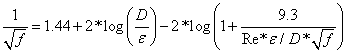
where
e = Surface roughness [m]
Re = Reynolds number = ![]()
A unique name for an AirflowNetwork duct component in an air distribution system. This unique name will be referenced by an AirflowNetwork:Distribution:Linkage object to represent a component.
This numeric field is used to input duct length [m]. This value must be greater than zero.
This numeric field is used to input hydraulic diameter, which is defined as:
![]()
where
Dh = Hydraulic diameter [m]
A = Duct cross sectional area [m2]
P = Perimeter of cross section [m]
This numeric field is used to input cross section area [m2]. The model assumes that this element has no area change along its length. Otherwise, effective cross sectional area is required.
This numeric field is used to input surface roughness [m]. This value must be greater than zero, and the default value is 0.0009 m.
This numeric field is defined as a coefficient for dynamic loss [dimensionless]. It represents dynamic loss due to fittings (such as an elbow).
This numeric field is defined as the overall heat transmittance coefficient (U value, W/m2-K) from air to air, including film coefficients at both surfaces.
This numeric field is defined as the overall moisture transmittance coefficient (kg/m2) from air to air, including film coefficients at both surfaces.
An IDF example is provided below:
AirflowNetwork:Distribution:Component:Duct,
MainTruck1, !- Name of Duct Component
3.0, !- Duct Length {m}
0.6, !- Hydraulic Diameter {m}
0.2827, !- Cross Section Area {m2}
0.0009, !- Surface Roughness {m}
0.01, !- Coefficient for local dynamic loss due to fitting {dimensionless}
0.772, !- Overall heat transmittance coefficient (U value) from air to air
!- {W/m2-K}
0.0001; !- Overall moisture transmittance coefficient from air to air {kg/m2}
This component represents a constant volume fan in the air distribution system (AirLoopHVAC). The air flow rate and air conditions (temperature and humidity) are obtained from the associated Fan:ConstantVolume or Fan:OnOff object.
The name identifying an AirflowNetwork constant volume fan in an air distribution system. This name must be the same as the name of the associated Fan:ConstantVolume or Fan:OnOff object. This name will be referenced by an AirflowNetwork:Distribution:Linkage object to represent a component.
This choice field defines the type of fan. The only valid choices are Fan:OnOff and Fan:ConstantVolume, with the default being Fan:ConstantVolume. Both cycling and continuous fan operating modes are allowed for Fan:OnOff. Only the continuous fan operating mode is allowed for Fan:ConstantVolume.
Note: Make sure that the volumetric air flow rates for the fan, coils, and parent components (e.g., unitary system or furnace) are the same so that fan energy and air distribution system losses/gains are properly calculated.
An IDF example is provided below:
AirflowNetwork:Distribution:Component:ConstantVolumeFan,
Supply Fan 1, !- Name of Constant Volume Fan
Fan:ConstantVolume; !- Supply fan type
This component represents a cooling or heating coil. The main purpose for this object is to get calculated values (air flow and temperature/humidity conditions) from the associated coil models.
The name identifying an AirflowNetwork cooling coil or heating coil defined in an air loop. This name must be the same name as the associated coil object. This unique name will be referenced by an AirflowNetwork:Distribution:Linkage object to represent a component.
This field requires input of the coil type used in the AirflowNetwork model. The available choices are:
n Coil:Cooling:DX:SingleSpeed
n Coil:Heating:Gas
n Coil:Heating:Electric
n Coil:Heating:DX:SingleSpeed
n Coil:Cooling:Water
n Coil:Heating:Water
n Coil:Cooling:Water:DetailedGeometry
n Coil:Cooling:DX:TwoStageWithHumidityControlMode
n Coil:Cooling:DX:MultiSpeed
n Coil:Heating:DX:MultiSpeed
n Coil:Heating:Desuperheater
This numeric field is used to input air path length for the coil [m]. This value must be greater than 0 meters.
This numeric field is used to input hydraulic diameter of a coil’s air path, which is defined as:
![]()
where
Dh = Hydraulic diameter [m]
A = Duct cross section area [m2]
P = Perimeter of cross section [m]
For this component, the relationship between airflow and pressure is similar to the component AirflowNetwork:Distribution:Component:Duct. However, the model assumes very small surface roughness (10-4) and no local dynamic loss due to fittings for this component. Therefore, this component only requires two numerical fields. Heat and moisture exchange from surroundings is ignored.
Note: Make sure that the volumetric air flow rates for the fan, coils, and parent components (e.g., unitary system or furnace) are the same so that fan energy and air distribution system losses/gains are properly calculated.
An IDF example is provided below:
AirflowNetwork:Distribution:Component:Coil,
ACDXCoil 1, !- Name of Associated EnergyPlus Coil
Coil:Cooling:DX:SingleSpeed, !- EnergyPlus Coil Type
0.1, !- Air Path Length {m}
1.00; !- Air Path Hydraulic Diameter {m}
AirflowNetwork:Distribution:Component:Coil,
HP Heating Coil 1, !- Name of Associated EnergyPlus Coil
Coil:Heating:DX:SingleSpeed, !- EnergyPlus Coil Type
0.1, !- Air Path Length {m}
1.00; !- Air Path Hydraulic Diameter {m}
This component represents an air-to-air heat exchanger typically used in combination with a cooling coil to enhance dehumidification or in an outside air system to recover energy from exhaust air to pretreat incoming outdoor ventilation air. The cooling coils with enhanced dehumidification are defined in the two objects CoilSystem:Cooling:DX:HeatExchangerAssisted and CoilSystem:Cooling:Water:HeatExchangerAssisted using one of three heat exchanger objects specified below. The exhaust air energy recovery system also has the same restriction using the one of three heat exchanger objects. The main purpose for this object is to obtain calculated values (air flow and temperature/humidity conditions) from the associated heat exchanger models for the airflow network calculations.
The name identifying an AirflowNetwork heat exchanger defined in an air loop. This name must be the same name that is used in the associated heat exchanger object. This unique name will be referenced by an AirflowNetwork:Distribution:Linkage object to represent a component.
This field requires input of the heat exchanger type. The available choices are:
n HeatExchanger:AirToAir:FlatPlate
n HeatExchanger:AirToAir:SensibleAndLatent
n HeatExchanger:Desiccant:BalancedFlow
This numeric field is used to input air path length for the heat exchanger coil [m]. This value must be greater than 0 meters.
This numeric field is used to input hydraulic diameter of a heat exchanger coil’s air path, which is defined as:
![]()
where
Dh = Hydraulic diameter [m]
A = Duct cross section area [m2]
P = Perimeter of cross section [m]
For this component, the relationship between airflow and pressure is similar to the component AirflowNetwork:Distribution:Component:Duct. However, the model assumes very small surface roughness (10-4) and no local dynamic loss due to fittings for this component. Therefore, this component only requires two numerical fields. Heat and moisture exchange from surroundings are ignored.
Note: When a heat exchanger is used as a component of either CoilSystem:Cooling:DX:HeatExchangerAssisted or CoilSystem:Cooling:Water:HeatExchangerAssisted, the heat exchanger acts as two components in an air primary loop. For example, an air-to-air heat exchanger has a component connected to the supply air side (equivalent to a supply coil) and a component connected to exhaust air side (equivalent to an exhaust coil). The desiccant heat exchanger has a component connected to regeneration air side (equivalent to a regeneration air coil) and a component connected to process air side (equivalent to a process air coil). Therefore, each air-to-air heat exchanger used in this configuration requires two linkage objects (instead of only one linkage object as required for other AirflowNetwork components).
When a heat exchanger is used in an exhaust air energy recovery system (i.e., in an AirLoopHVAC:OutdoorAirSystem object to recover waste heat from exhaust air to pretreat incoming outdoor ventilation air), the heat exchanger is treated as a single component. The AirflowNetwork model only connects the two nodes associated with the incoming outdoor ventilation air, while the two exhaust nodes are not defined as part of the AirflowNetwork model. Therefore, each heat exchanger component used in an exhaust air energy recovery system has only one linkage object, similar to AirflowNetwork coil components.
An IDF example is provided below:
AirflowNetwork:Distribution:Component:HeatExchanger,
OA Heat Recovery 1, !- HeatExchanger Name
HeatExchanger:AirToAir:SensibleAndLatent, !- HeatExchanger Object Type
0.1, !- Air Path Length {m}
1.00; !- Air Path Hydraulic Diameter {m}
AirflowNetwork:Distribution:Component:HeatExchanger,
Desiccant Heat Exchanger 1, !- HeatExchanger Name
HeatExchanger:Desiccant:BalancedFlow, !- HeatExchanger Object Type
0.1, !- Air Path Length {m}
1.00; !- Air Path Hydraulic Diameter {m}
This component represents a terminal unit for reheating the incoming supply air. The main purpose is to get calculated values from the terminal unit models.
A name identifying an AirflowNetwork terminal unit defined in a zone equipment list. This name must be the same as the associated terminal unit object. This unique name will be referenced by an AirflowNetwork:Distribution:Linkage object to represent a component.
This field requires input of the terminal unit type used in the AirflowNetwork model. The only available type is AirTerminal:SingleDuct:ConstantVolume:Reheat.
This numeric field is used to input the air path length for the terminal unit [m]. This value must be greater than 0 meters.
This numeric field is used to input hydraulic diameter for the terminal unit’s air path, which is defined as:
![]()
where
Dh = Hydraulic diameter [m]
A = Duct cross section area [m2]
P = Perimeter of cross section [m]
It should be noted that the relationship for this component between airflow and pressure is similar to the component AirflowNetwork:Distribution:Component:Duct. However, the model assumes very small surface roughness (10-4) and no local dynamic loss due to fittings for this component. Therefore, this component only requires two numerical fields. Heat and moisture exchange from surroundings is ignored.
Note: The AirflowNetwork:Distribution:Component:TerminalUnit object is used to represent an AirTerminal:SingleDuct:ConstantVolume:Reheat object in an AirflowNetwork simulation. The AirflowNetwork:Distribution:Component:TerminalUnit should not be used to represent any other air terminal unit types. When the ZoneHVAC:EquipmentList object specifies an Air:Terminal:SingleDuct:Uncontrolled object, the AirflowNetwork:Distribution:Component:Duct object should be used instead.
An IDF example is provided below:
AirflowNetwork:Distribution:Component:TerminalUnit,
Reheat Zone 1, !- Name of Associated Energyplus Terminal Unit
AirTerminal:SingleDuct:ConstantVolume:Reheat, !- EnergyPlus Terminal Unit Type
0.1, !- Air Path Length {m}
0.44; !- Air Path Hydraulic Diameter {m}
This component represents a constant pressure drop component. It is generally used to simulate a constant pressure drop filter. The mathematical equation may be written as:
![]()
A unique name identifying an AirflowNetwork constant pressure drop component in an air distribution system. This unique name will be referenced by an AirflowNetwork: Distribution:Linkage object to represent a component.
This numeric field is used to input the pressure difference across the element [Pa].
Note: This object should be used with caution. Each node connected to this object can not be a node for a mixer or splitter, a node in an AirLoopHVAC, or a node in a zone configuration loop. It is recommended that duct components be specified at both ends of this object.
An IDF example is provided below:
AirflowNetwork:Distribution:Component:ConstantPressureDrop,
SupplyCPDComp, ! Name of Constant Pressure Drop Component
1.0; ! Pressure Difference Across the Component [Pa]
The AirflowNetwork:Distribution:Linkage represents a connection between two AirflowNetwork:Distribution:Node objects and an AirflowNetwork component defined above. In addition, the relative height from node height to linkage height for each node is required.
The name identifies the linkage for later reference and in the output listing. Each linkage should have a unique name.
Designates a node name where airflow starts. The node name should be defined in an AirflowNetwork:Distribution:Node object.
Designates a node name where airflow ends. The node name should be defined in an AirflowNetwork:Distribution:Node object.
Designates an AirflowNetwork component name associated with the two nodes. The component name should be one of the AirflowNetwork:Distribution:Component… object names.
Designates a thermal zone where the linkage is located. The information provides the ambient conditions for duct elements to calculate duct conduction losses (only used if component is AirflowNetwork:Distribution:Component:Duct).
An IDF example is provided below:
AirflowNetwork:Distribution:Linkage,
Main Link 1, !- Name of Linkage
EquipmentInletNode, !- Node 1 Name
SupplyMainNode, !- Node 2 Name
MainTruck1, !- Component Name
Attic Zone; !- Thermal Zone Name
The AirflowNetwork nodes in the following output variables includes zones defined in AirflowNetwork:Multizone:Zone objects, external nodes defined in AirflowNetwork:MultiZone:ExternalNode objects, and nodes defined in AirflowNetwork:Distribution:Node objects.
The AirflowNetwork linkage used in following output variables includes surfaces defined in AirflowNetwork:Multizone:Surface objects, and linkages defined in AirflowNetwork:Distribution:Linkage objects. The surface linkages represent airflows through surface cracks or openings between two zones or between a zone and outdoors. The distribution linkages represent airflows in an air distribution system.
HVAC,Average,AirflowNetwork Node Temperature [C]
HVAC,Average,AirflowNetwork Node Humidity Ratio [kg/kg]
HVAC,Average,AirflowNetwork Node Total Pressure [Pa]
HVAC,Average,AirflowNetwork Wind Pressure [Pa]
HVAC,Average,AirflowNetwork Mass Flow Rate from Node 1 to 2 [kg/s]
HVAC,Average,AirflowNetwork Mass Flow Rate from Node 2 to 1 [kg/s]
HVAC,Average,AirflowNetwork Volume Flow Rate from Node 1 to 2 [m3/s]
HVAC,Average,AirflowNetwork Volume Flow Rate from Node 2 to 1 [m3/s]
HVAC,Average,AirflowNetwork Linkage Pressure Difference [Pa]
HVAC,Average,Window/Door Venting Opening Factor
HVAC,Average,Opening Factor Multiplier for Venting Modulation []
HVAC,Average,Inside Temp Setpoint for AirflowNetwork Venting [C]
HVAC,Average,Venting Availability []
HVAC,Average,AirflowNetwork Infiltration Sensible Gain Rate [W]
HVAC,Sum,AirflowNetwork Infiltration Sensible Gain [J]
HVAC,Average,AirflowNetwork Mixing Sensible Gain Rate [W]
HVAC,Sum,AirflowNetwork Mixing Sensible Gain [J]
HVAC,Average,AirflowNetwork Infiltration Sensible Loss Rate [W]
HVAC,Sum,AirflowNetwork Infiltration Sensible Loss [J]
HVAC,Average,AirflowNetwork Mixing Sensible Loss Rate [W]
HVAC,Sum,AirflowNetwork Mixing Sensible Loss [J]
HVAC,Average,AirflowNetwork Infiltration Latent Gain Rate [W]
HVAC,Sum,AirflowNetwork Infiltration Latent Gain [J]
HVAC,Average,AirflowNetwork Infiltration Latent Loss Rate [W]
HVAC,Sum,AirflowNetwork Infiltration Latent Loss [J]
HVAC,Average,AirflowNetwork Mixing Latent Gain Rate [W]
HVAC,Sum,AirflowNetwork Mixing Latent Gain [J]
HVAC,Average,AirflowNetwork Mixing Latent Loss Rate [W]
HVAC,Sum,AirflowNetwork Mixing Latent Loss [J]
HVAC,Average,AirflowNetwork Duct Leak Sensible Gain Rate [W]
HVAC,Sum,AirflowNetwork Duct Leak Sensible Gain [J]
HVAC,Average,AirflowNetwork Duct Leak Sensible Loss Rate [W]
HVAC,Sum,AirflowNetwork Duct Leak Sensible Loss [J]
HVAC,Average,AirflowNetwork Duct Leak Latent Gain Rate [W]
HVAC,Sum,AirflowNetwork Duct Leak Latent Gain [J]
HVAC,Average,AirflowNetwork Duct Leak Latent Loss Rate [W]
HVAC,Sum,AirflowNetwork Duct Leak Latent Loss [J]
HVAC,Average,AirflowNetwork Duct Conduction Sensible Gain Rate [W]
HVAC,Sum,AirflowNetwork Duct Conduction Sensible Gain [J]
HVAC,Average,AirflowNetwork Duct Conduction Sensible Loss Rate [W]
HVAC,Sum,AirflowNetwork Duct Conduction Sensible Loss [J]
HVAC,Average,AirflowNetwork Duct Diffusion Latent Gain Rate [W]
HVAC,Sum,AirflowNetwork Duct Diffusion Latent Gain [J]
HVAC,Average,AirflowNetwork Duct Diffusion Latent Loss Rate [W]
HVAC,Sum,AirflowNetwork Duct Diffusion Latent Loss [J]
HVAC,Average,AirflowNetwork Distribution Sensible Gain Rate [W]
HVAC,Sum,AirflowNetwork Distribution Sensible Gain [J]
HVAC,Average,AirflowNetwork Distribution Sensible Loss Rate [W]
HVAC,Sum,AirflowNetwork Distribution Sensible Loss [J]
HVAC,Average,AirflowNetwork Distribution Latent Gain Rate [W]
HVAC,Sum,AirflowNetwork Distribution Latent Gain [J]
HVAC,Average,AirflowNetwork Distribution Latent Loss Rate [W]
HVAC,Sum,AirflowNetwork Distribution Latent Loss [J]
HVAC,Sum,AirflowNetwork Zone Infiltration Volume [m3]
HVAC,Sum,AirflowNetwork Zone Infiltration Mass [kg]
HVAC,Average,AirflowNetwork Zone Infiltration Air Change Rate [ach]
HVAC,Sum,AirflowNetwork Zone Mixing Volume [m3]
HVAC,Sum,AirflowNetwork Zone Mixing Mass [kg]
The following are reported only when a Fan:OnOff object is used:
HVAC,Average,AirflowNetwork Average Zone Pressure [Pa]
HVAC,Average,AirflowNetwork Zone Pressure During ON cycle [Pa]
HVAC,Average,AirflowNetwork Zone Pressure During OFF cycle [Pa]
HVAC,Average,AirflowNetwork Average Mass Flow Rate from Node 1 to 2 [kg/s]
HVAC,Average,AirflowNetwork Average Mass Flow Rate from Node 2 to 1 [kg/s]
HVAC,Average,AirflowNetwork Average Volume Flow Rate from Node 1 to 2 [m3/s]
HVAC,Average,AirflowNetwork Average Volume Flow Rate from Node 2 to 1 [m3/s]
HVAC,Average,AirflowNetwork Surface Average Pressure Difference [Pa]
HVAC,Average,AirflowNetwork Surface Pressure Difference During ON cycle [Pa]
HVAC,Average,AirflowNetwork Surface Pressure Difference During OFF cycle [Pa]
This is the AirflowNetwork node temperature output in degrees C. When a Fan:OnOff object is used and is scheduled to operate in the cycling fan operation mode, this value for AirflowNetwork:Distribution:Node objects reflects the temperature when the fan is operating (ON).
This is the AirflowNetwork node humidity ratio output in kg/kg. When a Fan:OnOff object is used and is scheduled to operate in the cycling fan operation mode, this value for AirflowNetwork:Distribution:Node objects reflects the humidity ratio when the fan is operating (ON).
This is the AirflowNetwork node total pressure in Pa with respect to outdoor barometric pressure. The total pressure is the sum of static pressure, dynamic pressure, and elevation impact at the node’s relative height. When a Fan:OnOff object is used and is scheduled to operate in the cycling fan operation mode, the value for AirflowNetwork:Distribution:Node objects reflects the total pressure when the fan is operating (ON). The total pressures for nodes associate with AirflowNetwork:Multizone:Zone objects are reported in different output variables (below).
This is the AirflowNetwork average zone total pressure in Pa with respect to outdoor barometric pressure. This output is only available when a Fan:OnOff object is used in the air distribution system. The average zone pressure is weighted by the system fan part-load ratio using the calculated zone pressures during the fan on and off periods for the system timestep. The system fan part-load ratio is defined as the ratio of the air distribution system mass flow rate (average for the simulation timestep) to the system design mass flow rate.
Average zone pressure = (Zone pressure during on cycle * Part-load ratio) + Zone pressure during off cycle * (1.0 – Part-load ratio)
This is the AirflowNetwork zone total pressure in Pa with respect to outdoor barometric pressure when the air distribution system fan is operating (ON). This output is only available when a Fan:OnOff object is used in the air distribution system. When the fan part-load ratio is equal to 0.0, this pressure value will be zero because the air distribution system is not simulated when the fan is off for the entire timestep.
This is the AirflowNetwork zone total pressure in Pa with respect to outdoor barometric pressure when the air distribution system fan is not operating (OFF). This output is only available when a Fan:OnOff object is used in the air distribution system. Even if the fan part-load ratio is equal to 1.0, the pressure calculated as if the fan were not operating (OFF) is reported.
This is the AirflowNetwork wind pressure output in Pa. The wind pressure depends on several factors, including wind speed, wind direction, the wind-pressure coefficient (Cp) values for the AirflowNetwork:MultiZone:ExternalNode associated with the heat transfer surface and the site wind conditions.
When Wind Pressure Coefficient Type = “Input” in the AirflowNetwork:SimulationControl object, the output represents external node pressures driven by wind defined in an AirflowNetwork:MultiZone:ExternalNode object. When Wind Pressure Coefficient Type = “SurfaceAverageCalculation” in AirflowNetwork:SimulationControl, the program assumes five external nodes:
n FACADE1 Representing north orientation
n FACADE2 Representing east orientation
n FACADE3 Representing south orientation
n FACADE4 Representing west orientation
n ROOF Representing horizontal orientation
In this case, the output represents the wind pressures for the five external nodes defined above.
This is the AirflowNetwork linkage mass flow rate output in kg/s in the direction from Node 1 to Node 2. It reports surface airflows through a crack or opening, and through linkages defined in an AirflowNetwork:Distribution:Linkage object. The surface linkage is divided into two types of surfaces, exterior surface and interior surface. Node 1 for an exterior surface linkage is a thermal zone and Node 2 is an external node. The value of AirflowNetwork Mass Flow Rate from Node 1 to 2 represents the flow rate from a thermal zone to outdoors. The flow direction through an interior surface crack or opening is defined from a thermal zone defined by a surface’s Zone Name (Node 1) to an adjacent thermal zone defined by a surface’s OutsideFaceEnvironment (Node 2). For an AirflowNetwork:Distribution:Linkage object, the value represents the air mass flow rate flowing from Node 1 to Node 2.
It should be pointed out that in general, each linkage has one directional flow at any given time, either from Node 1 to 2 or from Node 2 to 1. However, there are two components which may have flows in both directions simultaneously: AirflowNetwork:MultiZone:Component:DetailedOpening and AirflowNetwork:MultiZone:Component:SimpleOpening.
When a Fan:OnOff object is used, the air mass flow rates reported for the AirflowNetwork:Distribution:Linkage objects are the values when the fan is operating (ON). It is assumed that the air mass flow rates when the fan is off are zero for the distribution system air linkage objects. The air mass flow rates for the AirflowNetwork:Multizone:Surface object are reported in different output variables (below).
This is the AirflowNetwork linkage mass flow rate output in kg/s in the direction from Node 2 to Node 1. It reports airflows from surfaces through a crack or opening, and from linkages defined in an AirflowNetwork:Distribution:Linkage object. Node 1 and Node 2 for a surface or subsurface are defined in the same manner as AirflowNetwork Mass Flow Rate from Node 1 to 2.
When a Fan:OnOff object is used, the air mass flow rates reported for the AirflowNetwork:Distribution:Linkage objects are the values when the fan is operating (ON). It is assumed that the air mass flow rates when the fan is off are zero for the distribution system air linkage objects. The air mass flow rates for the AirflowNetwork:Multizone:Surface object are reported in different output variables (below).
This is the AirflowNetwork linkage average mass flow rate in kg/s in the direction from Node 1 to Node 2 defined in the AirflowNetwork:Multizone:Surface objects. This output is only available when a Fan:OnOff object is used in the air distribution system. The average mass flow rate is weighted by the system fan part-load ratio using the calculated air mass flow rates during the fan on and off periods for the system timestep. The system fan part-load ratio is defined as the ratio of the air distribution system mass flow rate (average for the simulation timestep) to the system design mass flow rate.
Average surface mass flow rate = (Surface mass flow rate during on cycle * Part-load ratio) + Surface mass flow rate during off cycle * (1.0 – Part-load ratio)
This is the AirflowNetwork linkage average mass flow rate in kg/s in the direction from Node 2 to Node 1 defined in the AirflowNetwork:Multizone:Surface objects. This output is only available when a Fan:OnOff object is used in the air distribution system. The average mass flow rate is weighted by the system fan part-load ratio using the calculated air mass flow rates during the fan on and off periods for the system timestep. The system fan part-load ratio is defined as the ratio of the air distribution system mass flow rate (average for the simulation timestep) to the system design mass flow rate.
This is the AirflowNetwork linkage volume flow rate output in m3/s in the direction from the Node 1 to Node 2. It is defined in the same manner as AirflowNetwork Mass Flow Rate from Node 1 to 2.
When a Fan:OnOff object is used, the air volume flow rates reported for the AirflowNetwork:Distribution:Linkage objects are the values when the fan is operating (ON). It is assumed that the air volume flow rates when the fan is off are zero for the distribution system air linkage objects. The air volume flow rates for the AirflowNetwork:Multizone:Surface object are reported in different output variables (below).
This is the AirflowNetwork linkage volume flow rate output in m3/s in the direction from Node 2 to Node 1. It is defined in the same manner as AirflowNetwork Mass Flow Rate from Node 2 to 1.
When a Fan:OnOff object is used, the air volume flow rates reported for the AirflowNetwork:Distribution:Linkage objects are the values when the fan is operating (ON). It is assumed that the air volume flow rates when the fan is off are zero for the distribution system air linkage objects. The air volume flow rates for the AirflowNetwork:Multizone:Surface object are reported in different output variables (below).
This is the AirflowNetwork linkage average volume flow rate in m3/s in the direction from Node 1 to Node 2 defined in the AirflowNetwork:Multizone:Surface objects. This output is only available when a Fan:OnOff object is used. The average volume flow rate is weighted by the system fan part-load ratio using the calculated air volume flow rates during the fan on and off periods for the system timestep.
Average surface volume flow rate = (Surface volume flow rate during on cycle * Part-load ratio) + Surface volume flow rate during off cycle * (1.0 – Part-load ratio)
This is the AirflowNetwork linkage average volume flow rate in m3/s in the direction from Node 2 to Node 1 defined in the AirflowNetwork:Multizone:Surface objects. This output is only available when a Fan:OnOff object is used. The average volume flow rate is weighted by the system fan part-load ratio using the calculated air volume flow rates during the fan on and off periods for the system timestep.
This is the pressure difference across a linkage in Pa. The linkage includes both objects: AirflowNetwork:Multizone:Surface and AirflowNetwork: Distribution:Linkage.
When a Fan:OnOff object is used, the pressure differences reported for the AirflowNetwork:Distribution:Linkage objects are the values calculated when the fan is operating (ON). It is assumed that the pressure differences when the fan is off are zero for the distribution system air linkage objects. The pressure differences defined in the AirflowNetwork:Multizone:Surface are reported in different output variables (below).
This is the average pressure difference across a linkage in Pa for the AirflowNetwork:Multizone:Surface objects only when a Fan:OnOff object is used. The average pressure difference is weighted by the system fan part-load ratio using the calculated pressure differences during the fan on and off periods for the system timestep. The system fan part-load ratio is defined as the ratio of the air distribution system mass flow rate (average for the simulation timestep) to the system design mass flow rate.
Surface Average Pressure Difference = (Surface Average Pressure Difference during on cycle * Part-load ratio) + Surface Average Pressure Difference during off cycle * (1.0 - Part-load ratio)
This is the pressure difference across a linkage in Pa for the AirflowNetwork:Multizone:Surface objects only when the air distribution system fan is operating (ON). This output is only available when a Fan:OnOff object is used. When the fan part-load ratio is equal to 0.0, this pressure difference value will be zero because the air distribution system is not simulated when the fan is off for the entire timestep.
This is the pressure difference across a linkage in Pa for the AirflowNetwork:Multizone:Surface objects only when the air distribution system fan is not operating (OFF). This output is only available when a Fan:OnOff object is used. Even if the fan part-load ratio is equal to 1.0, the pressure difference calculated as if the fan were not operating (OFF) is reported.
The current time-step value of the venting opening factor for a particular window or door. When the window or door is venting, this is the input value of the opening factor (see AirflowNetwork:Multizone:Surface, Window/Door Opening Factor) times the multiplier for venting modulation (see description of next output variable, “Opening Factor Multiplier for AirflowNetwork Venting Modulation”). For example, if the input Window/Door opening factor is 0.5 and the modulation multiplier is 0.7, then the value of this output variable will be 0.5x0.7 = 0.35.
This is the multiplier on a window or door opening factor when venting modulation is in effect. See “Modulation of Openings” under AirflowNetwork:Multizone:Zone for a description of how the multiplier is determined.
When modulation is in effect the value of the multiplier is between 0.0 and 1.0. When modulation does not apply the value of the multiplier may be –1.0. When modulation applies but the surface is not venting, the value is –1.0. This is summarized in the following table. In this table, “Zone” means a thermal zone for which AirflowNetwork:Multizone:Zone has been specified. See AirflowNetwork: Multizone:Zone for definition of “Ventilation Control Mode.”
Table 25. Value of opening factor multiplier for different venting conditions.
|
Is surface in a Zone? |
Ventilation Control Mode |
Is surface venting? |
Value of opening factor multiplier |
|
Yes |
Temperature |
Yes |
0.0 to 1.0 |
|
No |
-1.0 |
||
|
Enthalpy |
Yes |
0.0 to 1.0 |
|
|
No |
-1.0 |
||
|
Constant |
Yes |
1.0 |
|
|
NoVent |
No |
-1.0 |
The time-step value of the venting setpoint temperature for the zone to which the surface belongs. This setpoint is determined from the Vent Temperature Schedule input (ref: AirflowNetwork:Multizone:Zone).
A value of 1.0 means venting through the surface can occur if venting control conditions are satisfied. A value of 0.0 means venting through the surface cannot occur under any circumstances. This value is determined by the Venting Availability Schedule input (ref: AirflowNetwork:Multizone:Zone or AirflowNetwork:Multizone: Surface).
The average convective sensible heat gain rate, in Watts, to the zone air corresponding to the Zone Infiltration Volume averaged over the reporting period. This value is calculated for each timestep when the outdoor dry-bulb temperature is higher than the zone temperature; otherwise, the sensible gain rate is set to 0.
When a Fan:OnOff object is used, this reported value is weighted by the system run time fraction using the calculated infiltration sensible gain rate during the system on and off cycles for the reporting period:
Infiltration Sensible Gain Rate = (Infiltration Sensible Gain Rate during on cycle * Run time fraction) + Infiltration Sensible Gain Rate during off cycle * (1.0 – Run time fraction)
The average convective sensible heat gain, in Joules, to the zone air corresponding to the Zone Infiltration Volume averaged over the reporting period. This value is calculated for each timestep when the outdoor dry-bulb temperature is higher than the zone temperature; otherwise, the sensible gain rate is set to 0.
When a Fan:OnOff object is used, the reported value is weighted by the system run time fraction using the calculated infiltration sensible gain during the system on and off cycles for the reporting period:
Infiltration Sensible Gain = (Infiltration Sensible Gain during on cycle * Run time fraction) + Infiltration Sensible Gain during off cycle * (1.0 – Run time fraction)
The average convective sensible heat loss rate, in Watts, to the zone air corresponding to the Zone Infiltration Volume averaged over the reporting period.
When a Fan:OnOff object is used, the reported value is weighted by the system run time fraction using the calculated infiltration sensible loss rate during the system on and off cycles for the reporting period:
Infiltration Sensible Loss Rate = (Infiltration Sensible Loss Rate during on cycle * Run time fraction) + Infiltration Sensible Loss Rate during off cycle * (1.0 – Run time fraction)
The average convective sensible heat loss, in Joules, to the zone air corresponding to the Zone Infiltration Volume averaged over the reporting period.
When a Fan:OnOff object is used, the reported value is weighted by the system run time fraction using the calculated infiltration sensible loss rate during the system on and off cycles for the reporting period:
Infiltration Sensible Loss = (Infiltration Sensible Loss during on cycle * Run time fraction) + Infiltration Sensible Loss during off cycle * (1.0 – Run time fraction)
The average convective latent heat gain rate, in Watts, to the zone air corresponding to the Zone Infiltration Volume averaged over the reporting period, when the outdoor humidity ratio is higher than the zone air humidity ratio.
When a Fan:OnOff object is used, the reported value is weighted by the system run time fraction using the calculated infiltration latent gain rate during the system on and off cycles for the reporting period:
Infiltration Latent Gain Rate = (Infiltration Latent Gain Rate during on cycle * Run time fraction) + Infiltration Latent Gain Rate during off cycle * (1.0 – Run time fraction)
The total convective latent heat gain, in Joules, to the zone air corresponding to the Zone Infiltration Volume summed over the reporting period.
When a Fan:OnOff object is used, the reported value is weighted by the system run time fraction using the calculated infiltration latent gain during the system on and off cycles for the reporting period:
Infiltration Latent Gain = (Infiltration Latent Gain during on cycle * Run time fraction) + Infiltration Latent Gain during off cycle * (1.0 – Run time fraction)
The average convective latent heat loss rate, in Watts, to the zone air corresponding to the Zone Infiltration Volume averaged over the reporting period.
When a Fan:OnOff object is used, the reported value is weighted by the system run time fraction using the calculated infiltration latent loss rate during the system on and off cycles for the reporting period:
Infiltration Latent Loss Rate = (Infiltration Latent Gain Loss Rate during on cycle * Run time fraction) + Infiltration Latent Loss Rate during off cycle * (1.0 – Run time fraction)
The total convective latent heat loss, in Joules, to the zone air corresponding to the Zone Infiltration Volume summed over the reporting period.
When a Fan:OnOff object is used, the reported value is weighted by the system run time fraction using the calculated infiltration latent loss during the system on and off cycles for the reporting period:
Infiltration Latent Loss = (Infiltration Latent Gain Loss during on cycle * Run time fraction) + Infiltration Latent Loss during off cycle * (1.0 – Run time fraction)
The average convective sensible heat gain rate, in Watts, to the zone air corresponding to the Zone Mixing Volume averaged over the reporting period. The mixing-volume is defined as incoming volume flow from other adjacent zones where the air temperature is higher than the temperature in this zone. For example, there are two zones (Zone 2 and Zone 3) adjacent to this zone (Zone 1). Zone 1 receives airflows from both Zone 2 and Zone 3. The air temperature is 21°C in Zone 1. The air temperatures are 20°C in Zone 2 and 22°C in Zone 3. The sensible gain rate only includes heat gain from Zone 3 with respect to Zone 1. The energy received from Zone 2 is considered as a sensible loss, instead of a gain, because the air temperature in Zone 2 is lower than in Zone 1.
When a Fan:OnOff object is used, the reported value is weighted by the system run time fraction using the calculated mixing sensible gain rate during the system on and off cycles for the reporting period:
Mixing Sensible Gain Rate = (Mixing Sensible Gain Rate during on cycle * Run time fraction) + Mixing Sensible Gain Rate during off cycle * (1.0 – Run time fraction)
The average convective sensible heat loss rate, in Watts, to the zone air corresponding to the Zone Mixing Volume averaged over the reporting period.
When a Fan:OnOff object is used, the reported value is weighted by the system run time fraction using the calculated mixing sensible loss rate during the on and off cycles for the reporting period:
Mixing Sensible Loss Rate = (Mixing Sensible Loss Rate during on cycle * Run time fraction) + Mixing Sensible Loss Rate during off cycle * (1.0 – Run time fraction)
The total convective sensible heat gain, in Joules, to the zone air corresponding to the Zone Mixing Volume summed over the reporting period.
When a Fan:OnOff object is used, the reported value is weighted by the system run time fraction using the calculated mixing sensible gain during the on and off cycles for the reporting period:
Mixing Sensible Gain = (Mixing Sensible Gain during on cycle * Run time fraction) + Mixing Sensible Gain during off cycle * (1.0 – Run time fraction)
The total convective sensible heat loss, in Joules, to the zone air corresponding to the Zone Mixing Volume summed over the reporting period.
When a Fan:OnOff object is used, the reported value is weighted by the system run time fraction using the calculated mixing sensible loss during the on and off cycles for the reporting period:
Mixing Sensible Loss = (Mixing Sensible Loss during on cycle * Run time fraction) + Mixing Sensible Loss during off cycle * (1.0 – Run time fraction)
The average convective latent heat gain rate, in Watts, to the zone air corresponding to the Zone Mixing Volume averaged over the reporting period.
When a Fan:OnOff object is used, the reported value is weighted by the system run time fraction using the calculated mixing latent gain rate during the on and off cycles for the reporting period:
Mixing Latent Gain Rate = (Mixing Latent Gain Rate during on cycle * Run time fraction) + Mixing Latent Gain Rate during off cycle * (1.0 – Run time fraction)
The total convective latent heat gain, in Joules, to the zone air corresponding to the Zone Mixing Volume summed over the reporting period.
When a Fan:OnOff object is used, the reported value is weighted by the system run time fraction using the calculated mixing latent gain during the on and off cycles for the reporting period:
Mixing Latent Gain = (Mixing Latent Gain during on cycle * Run time fraction) + Mixing Latent Gain during off cycle * (1.0 – Run time fraction)
The average convective latent heat loss rate, in Watts, to the zone air corresponding to the Zone Mixing Volume averaged over the reporting period.
When a Fan:OnOff object is used, the reported value is weighted by the system run time fraction using the calculated mixing latent loss rate during the on and off cycles for the reporting period:
Mixing Latent Loss Rate = (Mixing Latent Loss Rate during on cycle * Run time fraction) + Mixing Latent Loss Rate during off cycle * (1.0 – Run time fraction)
The total convective latent heat loss, in Joules, to the zone air corresponding to the Zone Mixing Volume summed over the reporting period.
When a Fan:OnOff object is used, the reported value is weighted by the system run time fraction using the calculated mixing latent loss during the on and off cycles for the reporting period:
Mixing Latent Loss = (Mixing Latent Loss during on cycle * Run time fraction) + Mixing Latent Loss during off cycle * (1.0 – Run time fraction)
This is the average sensible heat gain rate, in Watts, to a specific zone due to supply air leaks from the forced air distribution system. This value is averaged over the reporting period. A sensible heat gain occurs when duct air is warmer than zone air. It should be pointed out that when multiple supply air leaks are present in a single zone, the output value is the summation of all the supply air leak gains in this zone. When a Fan:OnOff object is used, the reported value is for the system on cycle.
This is the total sensible heat gain, in Joules, to a specific zone due to supply air leaks summed over the reporting period. When a Fan:OnOff object is used, the reported value is for the system on cycle.
This is the average sensible heat loss rate, in Watts, to a specific zone due to supply air leaks from the forced air distribution system. This value is averaged over the reporting period. A sensible heat loss occurs when duct air is cooler than zone air. It should be pointed out that when multiple supply air leaks are present in this zone, the output value is the summation of all the supply air leak losses in this zone. When a Fan:OnOff object is used, the reported value is for the system on cycle.
This is the total sensible heat loss, in Joules, to a specific zone due to supply air leaks summed over the reporting period. When a Fan:OnOff object is used, the reported value is for the system on cycle.
This is the average latent heat gain rate, in Watts, to a specific zone due to supply air leaks from the forced air distribution system for the reported time period. When a Fan:OnOff object is used, the reported value is for the system on cycle.
This is the total latent heat gain, in Joules, to a specific zone due to supply air leaks summed over the reporting period. When a Fan:OnOff object is used, the reported value is for the system on cycle.
This is the average latent heat loss rate, in Watts, to a specific zone due to supply air leaks from the forced air distribution system for the reported time period. When a Fan:OnOff object is used, the reported value is for the system on cycle.
This is the total latent heat loss, in Joules, to a specific zone due to supply air leaks summed over the reporting period. When a Fan:OnOff object is used, the reported value is for the system on cycle.
This is the average sensible heat gain rate, in Watts, of duct conduction to a specific zone where the ducts are located. This value is averaged over the reporting period. A sensible heat gain occurs when duct air is warmer than the zone air. It should be pointed out that when ducts are located in different zones, the total duct conduction loss should be the summation of the duct conduction losses in these zones. When a Fan:OnOff object is used, the reported value is for the system on cycle.
This is the total sensible heat gain, in Joules, to a specific zone due to duct conduction summed over the reporting period. When a Fan:OnOff object is used, the reported value is for the system on cycle.
This is the average sensible heat loss rate, in Watts, of duct conduction to a specific zone where the ducts are located. This value is averaged over the reporting period. A sensible heat loss occurs when duct air is cooler than the zone air. When a Fan:OnOff object is used, the reported value is for the system on cycle.
This is the total sensible heat loss, in Joules, to a specific zone due to duct conduction summed over the reporting period. When a Fan:OnOff object is used, the reported value is for the system on cycle.
This is the average latent heat gain rate, in Watts, of vapor diffusion through the walls of the air distribution system to a specific zone where the ducts are located. This value is averaged over the reporting period. When a Fan:OnOff object is used, the reported value is for the system on cycle.
This is the total latent heat gain, in Joules, to a specific zone due to duct vapor diffusion summed over the reporting period. When a Fan:OnOff object is used, the reported value is for the system on cycle.
This is the average latent heat loss rate, in Watts, of duct vapor diffusion to a specific zone where the ducts are located. This value is averaged over the reporting period. When a Fan:OnOff object is used, the reported value is for the system on cycle.
This is the total latent heat loss, in Joules, to a specific zone due to duct vapor diffusion summed over the reporting period. When a Fan:OnOff object is used, the reported value is for the system on cycle.
This is the average total sensible heat gain rate, in Watts, in a specific zone caused by the forced air distribution system. The total sensible gain rate is the sum of duct leakage sensible gain rate and duct conduction sensible gain rate. This value is averaged over the reporting period. The multizone airflow sensible gain rate is excluded in this output report variable. The output of multizone airflow sensible gain is reported in the previously-described output variables AirflowNetwork Infiltration Sensible Gain Rate and AirflowNetwork Mixing Sensible Gain Rate. When a Fan:OnOff object is used, the reported value is for the system on cycle.
This is the total sensible heat gain, in Joules, in a specific zone caused by the forced air distribution system. The total sensible gain is the sum of duct leakage sensible gain and duct conduction sensible gain. This value is summed over the reporting period. The multizone airflow sensible gain is excluded in this output report variable. The output of multizone airflow sensible gain is reported in the previously-described output variables AirflowNetwork Infiltration Sensible Gain and AirflowNetwork Mixing Sensible Gain. When a Fan:OnOff object is used, the reported value is for the system on cycle.
This is the average total sensible heat loss rate, in Watts, in a specific zone caused by the forced air distribution system. The total sensible loss rate is the sum of duct leakage sensible loss rate and duct conduction sensible loss rate. This value is averaged over the reporting period. The multizone airflow sensible loss rate is excluded in this output report variable. The output of multizone airflow sensible loss rate is reported in the previously-described output variables AirflowNetwork Infiltration Sensible Loss Rate and AirflowNetwork Mixing Sensible Loss Rate. When a Fan:OnOff object is used, the reported value is for the system on cycle.
This is the total sensible heat loss, in Joules, in a specific zone caused by the forced air distribution system. The total sensible loss is the sum of duct leakage sensible loss and duct conduction sensible loss. This value is summed over the reporting period. The multizone airflow sensible loss is excluded in this output report variable. The output of multizone airflow sensible loss is reported in the previously-described output variables AirflowNetwork Infiltration Sensible Loss and AirflowNetwork Mixing Sensible Loss. When a Fan:OnOff object is used, the reported value is for the system on cycle.
This is the average total latent heat gain rate, in Watts, in a specific zone caused by the forced air distribution system. The total latent gain rate is the sum of duct leakage latent gain rate and duct conduction latent gain rate. This value is averaged over the reporting period. When a Fan:OnOff object is used, the reported value is for the system on cycle.
This is the total latent heat gain, in Joules, in a specific zone caused by the forced air distribution system. The total latent gain is the sum of duct leakage latent gain and duct diffusion latent gain. This value is summed over the reporting period. When a Fan:OnOff object is used, the reported value is for the system on cycle.
This is the average total latent heat loss rate, in Watts, in a specific zone caused by the forced air distribution system. The total latent loss rate is a sum of duct leakage latent loss rate and duct diffusion latent loss rate. This value is averaged over the reporting period. When a Fan:OnOff object is used, the reported value is for the system on cycle.
This is the total latent heat loss, in Joules, in a specific zone caused by the forced air distribution system. The total latent loss is the sum of duct leakage latent loss and duct diffusion latent loss. This value is summed over the reporting period. When a Fan:OnOff object is used, the reported value is for the system on cycle.
NOTE: The following report variables should not be confused with similar report variables for the infiltration, mixing, and cross mixing objects (Ref. Infiltration Output, Mixing Output, or Cross Mixing Output). The report variables described below refer to infiltration, mixing, and cross-mixing when an Airflow Network Simulation is performed. The following report variables are always used to describe infiltration, mixing, and cross mixing when the AirflowNetwork Control field in the AirflowNetwork:SimulationControl object is set to “MultizoneWithoutDistribution” or “MultizoneWithDistribution”. In this case the report variables for the infiltration, mixing, and cross mixing objects will always be 0.
In contrast, the following report variables are only used to describe infiltration, mixing, and cross mixing when the AirflowNetwork Control field in the AirflowNetwork:SimulationControl object is set to “MultizoneAirflowWithDistributionOnlyDuringFanOperation” and the fan is operating. When the fan is not operating, the report variables for the infiltration, mixing, and cross mixing objects are used.
In the case where the AirflowNetwork Control field in the AirflowNetwork:SimulationControl object is set to “NoMultizoneOrDistribution”, the following report variables are not used and the report variables for the infiltration, mixing, and cross mixing objects are used instead.
The total convective sensible heat gain, in Joules, to the zone air corresponding to the Zone Infiltration Volume summed over the reporting period. This value is calculated for each timestep when the outdoor dry-bulb temperature is higher than the zone temperature, otherwise the sensible gain is set to 0. When a Fan:OnOff object is used, the reported value is for the system on cycle.
The total convective sensible heat loss, in Joules to the zone air corresponding to the Zone Infiltration Volume summed over the reporting period. When a Fan:OnOff object is used, the reported value is for the system on cycle.
The volume of outdoor air flow into the zone from window/door openings and cracks in the exterior surfaces of the zone (i.e., the sum of ventilation and crack flows from the exterior into the zone). The zone air density is used to calculate the zone infiltration volume based on the mass flow rate. Note that AirflowNetwork Zone Infiltration Volume will be zero if all of the flows through the zone’s exterior surfaces are out of the zone. When a Fan:OnOff object is used, the reported value is weighted by the system fan part-load ratio using the infiltration volume calculated during the fan on and off periods for the simulation timestep.
The mass of air corresponding to the AirflowNetwork Zone Infiltration Volume. When a Fan:OnOff object is used, the reported value is weighted by the system fan part-load ratio using the infiltration mass calculated during the fan on and off periods for the simulation timestep.
The number of air changes per hour produced by outdoor air flow into the zone from window/door openings and cracks in the exterior surfaces of the zone (i.e. the sum of ventilation and crack flows from the exterior into the zone). The target zone air density is used to calculate the zone infiltration air change rate based on the mass flow rate Note that, like Zone Infiltration Volume, Zone Infiltration Air Change Rate will be zero if all flows through the zone’s exterior surfaces are out of the zone. When a Fan:OnOff object is used, the reported value is weighted by the system fan part-load ratio using the infiltration air change rate calculated during the fan on and off periods for the simulation timestep.
This is a measure of interzone air flow for each thermal zone. It is the volume of air flow into the zone from adjacent zones through window/door openings and cracks in the interior heat transfer surfaces of the zone. The target zone air density is used to calculate the zone mixing volume based on the mass flow rate. This variable does not include flows that are from the zone to adjacent zones. Note that Zone Mixing Volume will be zero if all flows through the zone’s interior surfaces are out of the zone. When a Fan:OnOff object is used, the reported value is weighted by the system fan part-load ratio using the mixing volume calculated during the fan on and off periods for the simulation timestep.
The mass of air corresponding to the AirflowNetwork Zone Mixing Volume. When a Fan:OnOff object is used, the reported value is weighted by the system fan part-load ratio using the mixing mass calculated during the fan on and off periods for the simulation timestep.
There are five main zone equipment statements that must be used to describe a block of zone equipment as shown in the below figure “Zone Equipment Input Syntax Map”.
Types of Zone equipment are listed below and shown below in figure “Zone Equipment”.
Table 26. Available Zone Equipment Types
|
Air Distribution Equipment |
AirTerminal:SingleDuct:Uncontrolled AirTerminal:SingleDuct:ConstantVolume:Reheat AirTerminal:SingleDuct:VAV:Reheat AirTerminal:SingleDuct:VAV:NoReheat AirTerminal:SingleDuct:VAV:Reheat:VariableSpeedFan AirTerminal:DualDuct:ConstantVolume AirTerminal:DualDuct:VAV Powered Induction Units (Series and Parallel) |
|
Zone Forced Air Units
|
ZoneHVAC:IdealLoadsAirSystem ZoneHVAC:FourPipeFanCoil ZoneHVAC:WindowAirConditioner ZoneHVAC:RefrigerationChillerSet Unit Ventilator/Heater Air-to-Air Heat Pumps Unitary Systems (heat only and heat/cool) Furnaces (heat only and heat/cool) Energy Recovery Ventilator:Stand Alone AirLoopHVAC:UnitaryCoolOnly |
|
Radiative/Convective Units |
Baseboard Heaters Low Temp Radiant Systems High Temp Radiant System |
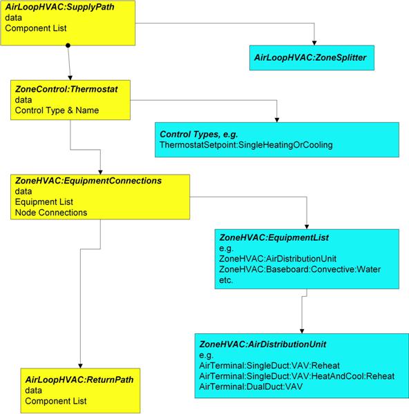
Figure 84. Zone Equipment Input Syntax Map
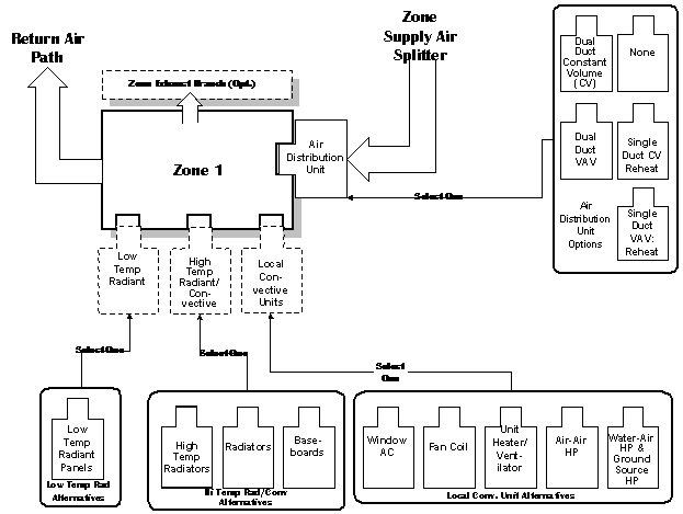
Figure 85. Representative Zone Equipment
The following figure (Air Loop/Zone Equipment Node Diagram) illustrates the connection between the zone equipment and the air loop systems.
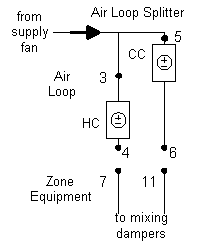
Figure 86. Air Loop/Zone Equipment Node Diagram
Each zone served by an HVAC system must have three additional statements to complete the zone equipment specification. An ZoneHVAC:AirDistributionUnit allows equipment typically found within the zone inlet ductwork (such as dampers, reheat coils, etc.) to be attached to the supply air stream for a particular zone. A ZoneControl statement will allow the conditions in the zone to be managed. Finally, a ZoneHVAC:EquipmentConnections statement describes all of the pertinent information about the zone from an HVAC perspective. Each of these statements is described in more detail below.
The ZoneHVAC:AirDistributionUnit object gives further information on what air loop equipment (air terminal units) will be serving a particular zone. The ZoneHVAC:AirDistributionUnit is the part of the system that is supplied from a common main air handler simulated in the Air Loop Simulation and includes the equipment that controls or tempers the air going to each individual zone according to the desired thermostatic control. The current options for ZoneHVAC:AirDistributionUnit terminal unit types are:
AirTerminal:DualDuct:ConstantVolume
AirTerminal:DualDuct:VAV
AirTerminal:DualDuct:VAV:OutdoorAir
AirTerminal:SingleDuct:ConstantVolume:Reheat
AirTerminal:SingleDuct:VAV:Reheat
AirTerminal:SingleDuct:VAV:NoReheat
AirTerminal:SingleDuct:SeriesPIU:Reheat
AirTerminal:SingleDuct:ParallelPIU:Reheat
AirTerminal:SingleDuct:ConstantVolume:FourPipeInduction
AirTerminal:SingleDuct:VAV:Reheat:VariableSpeedFan
AirTerminal:SingleDuct:VAV:HeatAndCool:Reheat
AirTerminal:SingleDuct:VAV:HeatAndCool:NoReheat
Connections between the air distribution unit, the supply air duct, and the zone are specified in the input syntax for the air distribution unit and the AirLoopHVAC:ZoneSplitter. The input syntax also explicitly defines an outlet identifier. This implies a connection to a zone through a NodeList for zone inlets (see the ZoneHVAC:EquipmentConnections statement). The air distribution unit is limited to one combined component-controller unit; because controls are normally based on the zone thermostat and can work in parallel or series in complex fashion. Since the control and the flow resolution can be complex, each air distribution unit is unique in addressing these combinations and therefore only one is allowed per zone.
The Air Distribution unit also allows the user to specify leaks in the supply air duct system. These inputs are used in the EnergyPlus Simplified Duct Leakage Model (SDLM). This model simulates a specific configuration: supply leaks to a return plenum in a commercial VAV or CV system. The system must have a constant static pressure setpoint. Within these limitations SDLM allows the user to easily evaluate the energy penalty due to duct leakage.
Unique identifying name of the air distribution unit.
Outlet node name for the air distribution unit to the attached zone.
Single combined component/controller unit for that attached zone. Selection of components as listed above.
The unique identifying component name.
This is the leakage upstream of the terminal unit as a fraction of the design flow rate through the unit. It is the leakage fraction at the design flow rate. It is used to calculate a leakage flow rate which is then held constant while the system air flow varies. This input is optional; the default is zero.
This is the leakage downstream of the terminal unit as a fraction of the current flow rate through the terminal unit. This fraction is held constant, so the leakage flow rate will vary proportinally with the supply air flow rate. This input is optional; the default is zero.
Two example IDF excerpts (one with duct leakage, one without):
ZoneHVAC:AirDistributionUnit,
SPACE1-1 ATU, !- Air Distribution Unit Name
SPACE1-1 In Node, !- Air Dist Unit Outlet Node Name
SINGLE DUCT:VAV:REHEAT, !- KEY--System Component Type 1
SPACE1-1 VAV Reheat; !- Component Name 1
ZoneHVAC:AirDistributionUnit,
SPACE4-1 ATU, !- Air Distribution Unit Name
SPACE4-1 In Node, !- Air Dist Unit Outlet Node Name
SINGLE DUCT:VAV:REHEAT, !- KEY--System Component Type 1
SPACE4-1 VAV Reheat, !- Component Name 1
0.05, !- upstream nominal leakage fraction
0.07; !- downstream constant leakage fraction
Finally, the ZoneHVAC:EquipmentConnections statement defines the remaining details about each thermal zone from an HVAC perspective (besides the controls which were defined above). As with other statements, the first two items in this object are the keyword and an identifying name which links the zone back to its geometrical input, internal gains, etc. and other statements in the HVAC section of the input. The next three items are names of lists (equipment, air inlet nodes, and air exhaust nodes) that are described in more detail below. Note that if there are no air exhaust nodes from the zone that field is left blank. And if there are no air inlet nodes, that field is left blank. Finally, two node names are necessary to complete the zone-HVAC description. The first node is the main air node for the zone upon which the air heat balance is performed. The other node begins the return air path from the zone.
Note that all nodes mentioned in the ZoneHVAC:EquipmentConnections input must be unique. That is, all nodes in all the ZoneHVAC:EquipmentConnections statements referenced by the “Zone Air Inlet Nodes”, “Zone Air Exhaust Nodes”, “Zone Air Node Name” and “Zone Return Air Node Name” cannot have any node name appearing more than once.
Name links this equipment list back to the heat balance for the zone.
List of zone equipment for this zone in a ZoneHVAC:EquipmentList object. This list will consist of air distribution units or other direct convection or radiant equipment, i.e. window air conditioner, baseboard, fan coils, etc.
There can be more than one air inlet node depending on how many pieces of equipment are in the ZoneHVAC:EquipmentList. Generally there will be one air inlet node for each piece of zone equipment that delivers conditioned air to the zone. Components such as electric or hot water baseboards and radiant systems do not require zone air inlet nodes. If there is only one node – its name can be put in this field. If there is more than one node, this must be the name of a node list object (a node list object can also contain only one node name). If this field is not required (as in the baseboard system), it should be blank.
List of exhaust nodes leaving the zone for exhaust fans, zone energy recovery, etc. However these nodes are also used as sources of zone air for zone components such as fan coil units, unit heaters and ventilators, and window air conditioners. For each such component attached to a zone there should be a unique zone exhaust node acting as the inlet node to the component. If there is only one node – its name can be put in this field. If there is more than one node, this must be the name of a node list object (a node list object can also contain only one node name). If there are no air exhaust nodes, this field should be blank.
The conditions at this node represent the average state of the air in the zone. For zones modeled as fully mixed the conditions at this node are assumed to represent the air in the entire zone. This field is required for all ZoneHVAC:EquipmentConnections statements.
The name of the return air node which attaches the zone to the return air path described above. Even if there is no return air or no return air path a unique name must be entered in this field. The conditions at this node represent the state of the air leaving the zone including any heat gain from light-heat-to-return.
An example of this statement in an IDF is:
ZoneHVAC:EquipmentConnections,
SPACE3-1, !- Zone Name
SPACE3-1 Eq, !- List Name: Zone Equipment
SPACE3-1 In Nodes, !- List Name: Zone Air Inlet Nodes
, !- List Name: Zone Air Exhaust Nodes
SPACE3-1 Node, !- Zone Air Node Name
SPACE3-1 Out Node; !- Zone Return Air Node Name
The first list encountered in the ZoneHVAC:EquipmentConnections statement is the ZoneHVAC:EquipmentList. This object lists all HVAC equipment serving the zone. Each item in the list has four fields associated with it: Object Type, Name, Cooling Sequence and Heating or No-Load Sequence The Object Type and Name identify the specific equipment object. Cooling Sequence and Heating or No-Load Sequence specify the order of simulation for zones with more than one type of HVAC equipment.
Note that a ZoneHVAC:AirDistributionUnit or AirTerminal:SingleDuct:Uncontrolled must be listed in this statement if there is a forced air system serving the zone from an air loop.
Unique identifying name.
This set is used together in order to sequence the equipment for heating and cooling. The #1 sequence equipment will try to meet the entire demand with its capacity and then pass the results on to the #2 and so on for both heating and cooling. This field set is extensible by duplicating the last four fields.
Equipment is simulated in the order specified by Zone Equipment Cooling Sequence and Zone Equipment Heating or No-Load Sequence, depending on the current thermostat request. For equipment of similar type, assign sequence 1 to the first system intended to serve that type of load, assign sequence 2 to the next system, and so on. For situations where one or more equipment types has limited capacity or limited control capability, order the sequence so that the most controllable piece of equipment runs last. For example, with a dedicated outdoor air system (DOAS), the air terminal for the DOAS should be assigned Heating Sequence = 1 and Cooling Sequence = 1. Any other equipment should be assigned sequence 2 or higher so that it will see the net load after the DOAS air is added to the zone.
Type of zone equipment such as air distribution unit, baseboard, window air conditioner, etc. The current legal types are listed in the following table:
Table 27. Legal Zone Equipment Types (ZoneHVAC:EquipmentList)
|
Legal Zone Equipment Types |
|
AirTerminal:SingleDuct:Uncontrolled |
|
Fan:ZoneExhaust |
|
WaterHeater:HeatPump |
|
ZoneHVAC:AirDistributionUnit |
|
ZoneHVAC:Baseboard:Convective:Electric |
|
ZoneHVAC:Baseboard:Convective:Water |
|
ZoneHVAC:Baseboard:RadiantConvective:Electric |
|
ZoneHVAC:Baseboard:RadiantConvective:Water |
|
ZoneHVAC:Baseboard:RadiantConvective:Steam |
|
ZoneHVAC:Dehumidifier:DX |
|
ZoneHVAC:EnergyRecoveryVentilator |
|
ZoneHVAC:FourPipeFanCoil |
|
ZoneHVAC:HighTemperatureRadiant |
|
ZoneHVAC:IdealLoadsAirSystem |
|
ZoneHVAC:LowTemperatureRadiant:ConstantFlow |
|
ZoneHVAC:LowTemperatureRadiant:Electric |
|
ZoneHVAC:LowTemperatureRadiant:VariableFlow |
|
ZoneHVAC:OutdoorAirUnit |
|
ZoneHVAC:PackagedTerminalAirConditioner |
|
ZoneHVAC:PackagedTerminalHeatPump |
|
ZoneHVAC:RefrigerationChillerSet |
|
ZoneHVAC:UnitHeater |
|
ZoneHVAC:UnitVentilator |
|
ZoneHVAC:WindowAirConditioner |
|
ZoneHVAC:WaterToAirHeatPump |
|
ZoneHVAC:VentilatedSlab |
Name of the zone equipment used in the object definition of its type.
Specifies the zone equipment simulation order when the zone thermostat requests cooling.
Specifies the zone equipment simulation order when the zone thermostat requests heating or no load.
Examples of this statement in an IDF are:
ZoneHVAC:EquipmentList,
Zone1Equipment, !- Name
ZoneHVAC:AirDistributionUnit, !- Zone Equipment 1 Object Type
Zone1TermReheat, !- Zone Equipment 1 Name
1, !- Zone Equipment 1 Cooling Sequence
1; !- Zone Equipment 1 Heating or No-Load Sequence
ZoneHVAC:EquipmentList,
Zone1Equipment, !- Name
AirTerminal:SingleDuct:Uncontrolled, !- Zone Equipment 1 Object Type
Zone1DirectAir, !- Zone Equipment 1 Name
1, !- Zone Equipment 1 Cooling Sequence
1, !- Zone Equipment 1 Heating or No-Load Sequence
ZoneHVAC:WaterToAirHeatPump, !- Zone Equipment 2 Object Type
Zone1WTAHP, !- Zone Equipment 2 Name
2, !- Zone Equipment 2 Cooling Sequence
2; !- Zone Equipment 2 Heating or No-Load Sequence
The systems described in the Air Distribution Units (ADU’s) are shown below. A variety of air terminal units are available for connecting air systems to thermal zones. These single description ADU’s contain the reference to the components and the actual controls in one block of input. The idea is that the control volume is drawn tightly around the controls and loosely around the components. This allows complex interactions to take place between all of the components that respond to the Zone Thermostatic Control output. The coils that are referenced in the ADU’s are explained fully in the “Coils” section of this manual.
Central system air is usually supplied to a zone through a terminal unit such as a single duct VAV reheat box. Sometimes, however, it is desirable to supply central system air directly to a zone without any zone level control or tempering. An example would be a single zone reheat system.
The control zone receives supply air directly from the central system since the supply air temperature has been adjusted to control the temperature in the control zone. The slave zones then have baseboards or reheat coils to allow some temperature adjustment. The AirTerminal:SingleDuct:Uncontrolled object creates the capability of supplying central system air directly to a zone. Its input consists of the object name, an availability (on/off) schedule, and a node name. This node is both a zone inlet node and an outlet node of the AirLoopHVAC:ZoneSplitter.
For the objects to work correctly, it is important in any systems including Direct Air objects for the sum of the maximum zone air flow rates to be equal to the maximum central system flow rate. The zone maximum flow rates are specified in the zone terminal unit or direct air inputs. The central air system flow rate is specified in the AirLoopHVAC input and also in the air loop branch and central fan inputs.
A unique user assigned name for each AirTerminal:SingleDuct:Uncontrolled component. Any other component that needs to use this direct air component will refer to it by this name.
The name of the schedule (ref: Schedule) that denotes whether the component can run during a given hour. A schedule value greater than 0 (usually 1 is used) indicates that the direct air component can be on during the hour. A value less than or equal to 0 (usually 0 is used) denotes that the direct air component must be off for the hour
The name of the node to which the direct air component is supplying air. This should be one of the supply air nodes for the zone the direct air component is serving. This node should also be an outlet node of a AirLoopHVAC:ZoneSplitter component.
The design maximum volume flow rate (m3/sec) specified for the AirTerminal:SingleDuct:Uncontrolled object. This field is autosizable.
An example input follows.
AirTerminal:SingleDuct:Uncontrolled,
Zone1DirectAir,
FanAndCoilAvailSched,
Zone 1 Inlet Node,
0.47;
AirTerminal:SingleDuct:Uncontrolled,
Zone2DirectAir,
FanAndCoilAvailSched,
Zone 2 Inlet Node,
0.36;
AirTerminal:SingleDuct:Uncontrolled,
Zone3DirectAir,
FanAndCoilAvailSched,
Zone 3 Inlet Node,
0.47;
HVAC,Sum,Direct Air Sensible Heating Energy [J]
HVAC,Sum,Direct Air Sensible Cooling Energy [J]
HVAC,Average,Direct Air Sensible Heating Rate [W]
HVAC,Average,Direct Air Sensible Cooling Rate [W]
These outputs are the sensible heating power and energy provided to the zone by the uncontrolled air terminal unit.
These outputs are the sensible cooling power and energy provided to the zone by the uncontrolled air terminal unit.
The AirTerminal:SingleDuct:ConstantVolume:Reheat or terminal reheat system is a constant volume reheat system. The systems cooling capabilities are provided by way of cooling coil that supplies cooling to the entire supply air volume. The cooling coil is controlled by a controller setpoint specified for the cooling coil. Zone control is accomplished by heating (reheating) the airflow into each zone as determined by the zone thermostat. Currently the reheat can be supplied by a electric, gas, or hot water coil that tries to meet the zone demand.
Unique name for the terminal reheat Air Distribution Unit (ADU).
Schedule that this component will operate or is available to operate.
The outlet node from the ADU to the zone. This is the same node as the reheat component air outlet node.
The air-inlet node name that connects the air splitter to the individual zone ADU. This is the same node as the reheat component air inlet node.
The design constant volume flow rate (m3/sec) specified for the terminal reheat ADU.
The last several fields for this object describe the type of reheat coil that is being used and how it is controlled. Most of the fields pertain to the hot water coil since the gas and electric coil are much more simplified.
For the hot water reheat coil there is a node on the water side that would control the flow to the coil capacity to allow the coil to meet the zone demand. This control location is the name of the control node for the terminal reheat ADU. For the gas and electric coil this is left blank.
The valid reheat component objects currently available are:
Coil:Heating:Water
Coil:Heating:Electric
Coil:Heating:Gas
Coil:Heating:Steam
Reheat Coil Object name being simulated with this ADU. Applicable for all coils.
This field is 0 for gas and electric coils. Set to the maximum design water flow (m3/sec) for the hot water coil
This field is zero for gas and electric coils. Set to the minimum design water flow (m3/sec) for the hot water coil, normally set to be a shut off valve that is set to zero.
The coil is controlled by knowing the zone demand determined by the zone thermostat and setting the outlet conditions to meet this demand. For the electric and gas coils, this is set exactly since the coil model solution can be inverted. With the hot water coil that uses an effectiveness-NTU method, the solution cannot be inverted directly. Therefore, to determine the correct mass flow rate for the hot water the solution is solved for by iteration. The iterative solution uses an interval halving routine and needs a termination criteria that is set with the Convergence Tolerance parameter. This control offset is set to a decimal fraction of the zone demand as the criteria, i.e. 0.001. The default for the field is 0.001.
This is the upper limit on the temperature in degrees C of the air leaving the terminal unit – reheat coil (and being delivered to the zone). If the user leaves this field blank, no maximum reheat air temperature is enforced.
An IDF example:
AirTerminal:SingleDuct:ConstantVolume:Reheat,
Reheat Zone 1, !- Name of System
FanAndCoilAvailSched, !- Availability schedule for VAV System
Zone 1 Reheat Air Outlet Node, !- Unit Air Outlet Node
Zone 1 Reheat Air Inlet Node, !- Unit Air Inlet Node
0.59, !- Maximum air flow rate {m3/s}
, !- Control node
COIL:Gas:Heating, !- Reheat Component Object
Reheat Coil Zone 1, !- Name of Reheat Component
0.0, !- Max Reheat Water Flow {m3/s}
0.0, !- Min Reheat Water Flow {m3/s}
0.001; !- Convergence Tolerance
There are no outputs for the constant volume reheat air terminal.
AirTerminal:SingleDuct:VAV:Reheat - Variable air volume (VAV) systems control the dry-bulb temperature inside a zone by varying the supply air volume instead of the air temperature. At full cooling the VAV damper is fully open supplying the specified maximum air flow rate. As the cooling load decreases, the damper closes until it reaches the minimum stop specified by the zone minimum air flow fraction.
VAV systems can be used for interior or perimeter zones with a common fan system, air temperature control, and reheating devices. The VAV concept may vary according to the VAV box locations, air temperature controls and types of heating elements. Heating can usually be provided by use of reheat coils or thermostatic baseboard.
Unique name for the AirTerminal:SingleDuct:VAV:Reheat Air Distribution Unit (ADU).
Schedule that this component will operate or is available to operate.
The VAV damper outlet node. This is the outlet node of the damper and the inlet node of the reheat coil.
The air inlet node name that connects the air splitter to the individual zone ADU. This is not the same as the air inlet node of the reheat component: it is upstream of that node. This is the inlet node to the terminal unit and the damper
The design maximum volume flow rate (m3/sec) specified for VAV ADU.
This field is used to select how the program will determine the minimum flow rate to the zone while the system is operating. There are three choices for selecting how the minimum flow rate is specified: Constant, FixedFlowRate, and Scheduled. If Constant is entered, then the program will use the value for the constant minimum air flow fraction entered in the following field. If FixedFlowRate is entered, then the program will use the value entered in the field below called Fixed Minimum Air Flow Rate. If Scheduled is entered, then the program will obtain the value for minimum flow fraction from the schedule named in the field below called Minimum Air Flow Fraction Schedule Name.
The minimum flow rate to the zone while the system is operating, specified as a fraction of the maximum air flow rate. The minimum zone fraction is normally specified to meet the minimum ventilation requirement for the occupants. The reheat coil operates only when the damper is at this minimum flow rate when Damper Heating Action is set to Normal (the default). This field is used if the previous field is set to Constant. If the previous field is set to Scheduled (and the field Maximum Hot Water or Steam Flow Rate is set to autosize), then this field is optional and can be used to separately control the air flow rate used for sizing normal-action reheat coils. If this field and the following field have values, the greater of the two is used for sizing.
The minimum flow rate to the zone while the system is operating, specified as a fixed minimum air flow rate in meters cubed per second. The minimum air flow rate is normally specified to meet the minimum ventilation requirement for the occupants. The reheat coil operates only when the damper is at this minimum flow rate when Damper Heating Action is set to Normal (the default). This field is used if the Zone Minimum Air Flow Method field is set to FixedFlowRate. If the Zone Minimum Air Flow Method field is set to Scheduled (and the field Maximum Hot Water or Steam Flow Rate is set to autosize), then this field is optional and can be used to separately control the air flow rate used for sizing normal-action reheat coils. Only one of these two minimum air flow fields (i.e., this field and the previous field) should be used at any time. If this field and the previous field have values, the greater of the two is used for sizing.
The name of a schedule that determines the value of the minimum air flow fraction. The schedule should contain fractions from 0.0 to 1.0. These values will define the minimum flow rate to the zone while the system is operating, specified as a fraction of the maximum air flow rate. The reheat coil operates only when the damper is at this minimum flow rate when Damper Heating Action is set to Normal (the default). This field is used if the previous field is set to Scheduled. If the previous field is left blank (and the field Maximum Hot Water or Steam Flow Rate is set to autosize), then the air flow rate used for sizing normal-action reheat coils is the average of the minimum and maximum values in this schedule. The air flow rate used for reheat coil sizing is reported with other component sizing information as “Reheat Coil Sizing Air Volume Flow Rate.”
The valid reheat component objects currently available are:
Coil:Heating:Water
Coil:Heating:Electric
Coil:Heating:Gas
Coil:Heating:Steam
If there is no reheat coil,use Single Duct:VAV:NoReheat instead of this object.
Reheat Coil Object name being simulated with this ADU. Applicable for all coils. If there is no reheat coil,use object AirTerminal:SingleDuct:VAV:NoReheat instead of this object.
This field is 0 for gas and electric coils. Set to the maximum design water flow (m3/sec) for the hot water coil. This field is autosizable. If there is no reheat coil, this is left blank.
This field is zero for gas and electric coils. Set to the minimum design water flow (m3/sec) for the hot water coil, normally set to be a shut off valve that is set to zero. If there is no reheat coil, this is left blank.
The terminal unit outlet node. This is the outlet node of the reheat coil and the zone inlet node.
The coil is controlled by knowing the zone demand determined by the zone thermostat and setting the outlet conditions to meet this demand. For the electric and gas coils, this is set exactly since the coil model solution can be inverted. With the hot water coil that uses an effectiveness-NTU method, the solution cannot be inverted directly. Therefore, to determine the correct mass flow rate for the hot water the solution is solved for by iteration. The iterative solution uses an interval halving routine and needs a termination criteria that is set with the Convergence Tolerance parameter. This control offset is set to a decimal fraction of the zone demand as the criteria, i.e. 0.001. The default for the field is 0.001.
in the VAV terminal unit as the zone moves above or below the zone setpoint. With both control options, the damper is at the minimum air flow rate whenever the zone temperature is between the cooling and heating setpoints (deadband condition).
With Normal (the default) action, the damper will remain at the minimum air flow rate during heating operation. As the heating load increases, the water flow rate in the reheat coil will be increased to maintain temperature in the zone until the maximum water flow rate is reached or the user-specified maximum reheat air temperature is reached.. This is sometimes called the single maximum control logic as illustrated below.
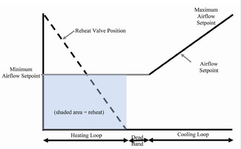
Figure 87. The Single Maximum Control Logic
With Reverse, as the heating load increases, the unit starts at minimum air flow and minimum hot water flow. The hot water flow is increased until it reaches maximum flow or the user-specified maximum reheat air temperature is reached, then the air damper starts to open to meet the load. This option is used if the minimum air flow rate is not adequate to serve the peak heating load. This is sometimes called the dual maximum control logic as illustrated in following figure. For heating coil types other than the hot-water coil, e.g. electric, steam, and gas, the reverse action works the same as the normal action – always keeping the air flow at the minimum during heating.
The dual-max control currently applies to the AirTerminal:SingleDuct:VAV:Reheat objects with reverse acting dampers and hot-water coils.
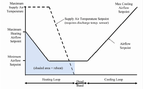
Figure 88. The Dual Maximum Control Logic
The following two fields are used only when Reheat Coil Object Type = Coil:Heating:Water and Damper Heating Action = Reverse. Maximum Flow per Zone Floor Area During Reheat and Maximum Flow Fraction During Reheat are two optional methods to calculate the maximum allowable air flow rate during reheat operation. If both are entered, the greater resulting flow rate is used. If Design Specification Outdoor Air Object Name is also specified, it may increase this limit to meet the outdoor air flow rate requirement. At no time will the maximum flow rate calculated here exceed the value for Maximum Air Flow Rate.
This limit is active only when the zone thermostat requests heating and the VAV box damper is reverse acting.
This factor (m3/s-m2) is multiplied by the zone area, to determine the maximum volume flow rate (m3/s) allowed during reheat operation (see detailed explanation above). This field is autocalculatable. If autocalculate is selected, the value is set to 0.002032 m3/s-m2 (0.4 cfm/ft2). If this field and the following field are entered, the greater of the two inputs is used. If this field and the following field are left blank, the maximum flow will not be limited.
This fraction is multiplied by the Maximum Air Flow Rate to determine the maximum volume flow rate (m3/s) allowed during reheat operation (see detailed explanation above). This field is autocalculatable. If autocalculate is selected, the value is set to 0.002032 m3/s-m2 (0.4 cfm/ft2) multiplied by the zone floor area divided by the Maximum Air Flow Rate. If this field and the previous field are entered, the greater of the two inputs is used. If this field and the previous field are left blank, the maximum flow will not be limited.
This field specifies a maximum supply air temperature (°C) leaving the reheat coil in a VAV terminal unit during heating operation. If leaving blank, the temperature of the supply air to the space in heating operation may get unrealistic high.
This alpha field specifies the name of a DesignSpecification:OutdoorAir object. When this field is used, the terminal unit will increase flow as needed to meet this outdoor air requirement. If Outdoor Air Flow per Person is non-zero, then the outdoor air requirement will be computed based on the current number of occupants in the zone. At no time will the supply air flow rate exceed the value for Maximum Air Flow Rate. If this field is blank, then the terminal unit will not be controlled for outdoor air flow. See documentation for the zone HVAC outdoor air object for further information (Ref DesignSpecification:OutdoorAir).
An IDF example:
AirTerminal:SingleDuct:VAV:Reheat,
SPACE2-1 VAV Reheat, !- Name of System
ReheatCoilAvailSched, !- Availability schedule for VAV System
SPACE2-1 Zone Coil Air In Node, !- Damper Air Outlet Node
SPACE2-1 ATU In Node, !- Unit Air Inlet Node
autosize, !- Maximum air flow rate {m3/s}
Constant, !- Zone Minimum Air Flow Input Method
0.3, !- Constant Minimum Air Flow Fraction
, !- Fixed Minimum Air Flow Rate
, !- Minimum Air Flow Fraction Schedule Name
COIL:Gas:Heating, !- Reheat Component Object
SPACE2-1 Zone Coil, !- Name of Reheat Component
0.0, !- Max Reheat Water Flow {m3/s}
0.0, !- Min Reheat Water Flow {m3/s}
SPACE2-1 In Node, !- Unit Air Outlet Node
0.001, !- Convergence Tolerance
Reverse, !- Damper Heating Action
, !- Maximum Flow per Zone Floor Area During Reheat
, !- Maximum Flow Fraction During Reheat
35.0, !- Maximum Reheat Air Temperature {C}
; !- Design Specification Outdoor Air Object Name
DesignSpecification:OutdoorAir,
ZoneMinOARequirements, !- Name
Sum, !- Outdoor Air Method
0.00472, !- Outdoor Air Flow per Person {m3/s}
0.000508, !- Outdoor Air Flow per Zone Floor Area {m3/s-m2}
, !- Outdoor Air Flow per Zone
, !- Outdoor Air Flow Air Changes per Hour
Min OARequirements Sched; !- Outdoor Air Flow Rate Fraction Schedule Name
Schedule:Compact,
Min OARequirements Sched, !- Name
Any Number, !- Schedule Type Limits Name
Through: 12/31, !- Field 1
For: Weekdays SummerDesignDay WinterDesignDay, !- Field 2
Until: 24:00,1.0, !- Field 7
For: AllOtherDays, !- Field 9
Until: 24:00,0.25; !- Field 10
COIL:Heating:Gas,
SPACE1-1 Zone Coil, !- Coil Name
ReheatCoilAvailSched, !- Available Schedule
0.8, !- Gas Burner Efficiency of the Coil
autosize, !- Nominal Capacity of the Coil {W}
SPACE1-1 Zone Coil Air In Node, !- Coil_Air_Inlet_Node
SPACE1-1 In Node; !- Coil_Air_Outlet_Node
HVAC,Average,VAV Terminal Damper Position []
HVAC,Average,VAV Terminal Minimum Air Flow Fraction []
HVAC,Average,VAV Terminal Outdoor Air Flow Rate [m3/s]
This output is the variable air volume damper position required to meet the zone load. This is the average value over the frequency being reported. The damper position is defined as the terminal unit air mass flow rate divided by the terminal unit’s maximum air mass flow rate.
This output is the value for the minimum air flow fraction setting on a VAV terminal. This is the average value over the frequency being reported. The minimum air flow fraction is defined as the lower limit on the terminal unit air mass flow rate divided by the terminal units maximum air mass flow rate.
This output is the amount of outdoor air entering the zone. This is the average value over the frequency being reported. The amount of outdoor air is defined as the terminal unit air volume flow rate multiplied by the fraction of outdoor air entering the air loop’s outside air system.
The VAV terminal unit with variable-speed fan and reheat coil is an air system terminal unit consisting of a variable speed fan in series with a heating coil. These units are usually employed in underfloor air distribution (UFAD) systems where the air is supplied at low static pressure through an underfloor plenum. The fan is used to control the flow of conditioned air that enters the space. When the fan is off the plenum pressure drives the minimum air flow through the terminal unit. At maximum cooling the fan runs at its maximum speed. At full heating the fan runs at its heating maximum – usually less than the cooling maximum flow rate. Thus this unit has two separate maximum flow rates – one for heating and one for cooling.
For cooling, control is maintained simply by varying the fan speed. For heating, the unit first tries to meet the heating load by varying the heating coil output while keeping the air flow at minimum (fan off). If this is not adequate the fan turns on and operates in variable flow mode up to the heating maximum flow rate.
This unit is modeled in EnergyPlus as a compound component – a variable speed fan and a heating coil in series in the air stream. The unit is blow through – the fan is upstream of the heating coil.
A unique user assigned name for a particular VS fan VAV reheat terminal unit. Any reference to this unit by another object will use this name.
The name of the schedule (ref: Schedule) that denotes whether the unit can run during a given hour. A schedule value greater than 0 (usually 1 is used) indicates that the unit can be on during the hour. A value less than or equal to 0 (usually 0 is used) denotes that the unit must be off for the hour.
The maximum volumetric air flow rate through the unit in cubic meters per second when the thermostat is calling for cooling. Normally this is the same as the unit’s fan maximum volumetric flow rate.
The maximum volumetric air flow rate through the unit in cubic meters per second when the thermostat is calling for heating.
The minimum flow rate to the zone while the system is operating, specified as a fraction of the maximum air flow rate. For this unit this is the flow rate when the fan is off.
The name of the HVAC system node that is the air inlet node for the terminal unit. This is also the air inlet node for the unit’s fan.
The name of the HVAC system node that is the air outlet node of the unit. This same node will be the unit heating coil’s air outlet node. This node is also a zone inlet node.
The name of the HVAC system node that is the air inlet node of the unit’s heating coil. The same node is the outlet node of the unit’s fan. This is an internal node of this compound component.
The name of the HVAC system node which regulates the flow of hot water through the unit’s hot water heating coil. This should be the same node as the water inlet node of the hot water coil. For gas or electric coils this field should be left blank.
The type of fan in the terminal unit. At this time the only type of fan allowed is Fan:VariableVolume.
The name of the particular fan object in this terminal unit.
The type of heating coil in the terminal unit. The valid choices are:
Coil:Heating:Water
Coil:Heating:Electric
Coil:Heating:Gas
Coil:Heating:Steam
The name of the heating coil object contained in this terminal unit.
The maximum hot water volumetric flow rate in m3/sec through the unit’s heating coil. If the heating coil is not a hot water coil this field should be left blank.
The minimum hot water volumetric flow rate in m3/sec through the unit’s heating coil. If the heating coil is not a hot water coil this field should be left blank.
The control tolerance for the unit heating output. The unit is controlled by matching the unit output to the zone demand. The model must be numerically inverted to obtain a specified output. The convergence tolerance is the error tolerance used to terminate the numerical inversion procedure. Basically this is the fraction:
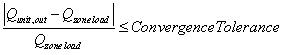
The default is 0.001.
An IDF example:
AirTerminal:SingleDuct:VAV:Reheat:VariableSpeedFan,
SPACE2-1 VAV Reheat, !- Name of System
ReheatCoilAvailSched, !- System Availability schedule
autosize, !- Maximum cooling air volume flow rate
autosize, !- Maximum heating air volume flow rate
0.05, !- Zone Minimum Air Flow Fraction
SPACE2-1 ATU In Node, !- Unit supply air inlet node
SPACE2-1 In Node, !- Unit supply air outlet node
SPACE2-1 Zone Coil Air In Node, !- heating coil air inlet node
SPACE2-1 Zone Coil Water In Node,!- Hot water control node
FAN:SIMPLE:VariableVolume, !- Fan object
SPACE2-1 Zone Fan, !- Fan name
COIL:Water:SimpleHeating,!- Heating coil object
SPACE2-1 Zone Coil, !- Heating coil name
autosize, !- Max hot water flow
0.0, !- Min hot water flow
0.001; !- Heating Convergence Tolerance
Coil:Heating:Water,
SPACE2-1 Zone Coil, !- Coil Name
ReheatCoilAvailSched, !- Available Schedule
autosize, !- UA of the Coil {W/K}
autosize, !- Max Water Flow Rate of Coil {m3/s}
SPACE2-1 Zone Coil Water In Node, !- Coil_Water_Inlet_Node
SPACE2-1 Zone Coil Water Out Node, !- Coil_Water_Outlet_Node
SPACE2-1 Zone Coil Air In Node, !- Coil_Air_Inlet_Node
SPACE2-1 In Node; !- Coil_Air_Outlet_Node
Fan:VariableVolume,
SPACE2-1 Zone Fan, !- Fan Name
FanAvailSched, !- Available Schedule
0.7, !- Fan Total Efficiency
125.0, !- Delta Pressure {Pa}
autosize, !- Max Flow Rate {m3/s}
0.0, !- Min Flow Rate {m3/s}
0.9, !- Motor Efficiency
1.0, !- Motor In Airstream Fraction
0.00153028, !- FanCoefficient 1
0.00520806, !- FanCoefficient 2
1.1086242, !- FanCoefficient 3
-.11635563, !- FanCoefficient 4
0.000, !- FanCoefficient 5
SPACE2-1 ATU In Node, !- Fan_Inlet_Node
SPACE2-1 Zone Coil Air In Node; !- Fan_Outlet_Node
HVAC,Average,VAV Terminal Flow Fraction []
This output is the variable air volume flow fraction required to meet the zone load. This is the average value over the frequency being reported. The flow fraction is defined as the terminal unit air mass flow rate divided by the terminal unit’s maximum air mass flow rate.
Variable air volume (VAV) systems typically control the dry-bulb temperature inside a zone by varying the supply air volume instead of the supply air temperature (ref: AirTerminal:SingleDuct:VAV:NoReheat). Reheat coils may be required to avoid overcooling (ref: AirTerminal:SingleDuct:VAV:Reheat).
This terminal unit is slightly different from the Single Duct:VAV:Reheat terminal unit. Both operate the same in cooling mode: the damper opens as needed to provide additional sensible cooling to the zone. The difference between the two is in heating mode. For the Single Duct VAV Reheat terminal unit, the air flow rate is reduced to the minimum value (max air flow rate x zone minimum air flow fraction) when zone heating is required and the reheat coil output is modulated to meet the zone heating load. For the AirTerminal:SingleDuct:VAV:HeatAndCool:Reheat terminal unit, the air flow rate in heating mode is increased to meet higher zone heating loads (similar to what is done in cooling mode). If additional heat is required (beyond what the terminal unit can provide with its damper fully open), then the reheat coil is modulated as needed to meet the additional heating load.
This terminal unit model was originally developed and tested for use with the changeover-bypass VAV unitary system.
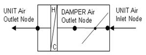
Figure 89. Single Duct VAV Heat and Cool Reheat Schematic
Unique user-defined name for this Air Distribution Unit (ADU).
This alpha field defines the name of the schedule (ref: Schedule) that denotes whether or not this component is available to operate during a given time period. If a schedule value is greater than zero then the system is available to operate; otherwise, the system is unavailable for that time period.
This alpha field defines the name of the VAV damper air outlet node. This is the outlet node of the damper and the inlet node of the reheat coil.
This alpha field defines the name of the air inlet node that connects the air splitter to the individual zone ADU. This is not the same as the air inlet node of the reheat component: it is upstream of that node. This is the inlet node to the terminal unit and the damper.
This numeric field defines the design maximum volumetric flow rate (m3/sec) specified for this VAV ADU. This flow rate must be greater than 0 or can be autosized.
This numeric field defines the minimum air volumetric flow rate to the zone while the system is operating, specified as a fraction of the maximum air flow rate. The minimum zone fraction is normally specified to meet the minimum ventilation requirement for the occupants. The reheat coil operates as needed to maintain the heating set point specified in the Zone Control:Thermostatic object. This value must be between 0 and 1.
The last several fields for this terminal reheat component describe the type of reheat coil that is being used and how it is controlled. Most of the fields pertain to the hot water coil since the gas and electric coil are much more simplified.
For the hot water reheat coil there is a node on the water side that would control the water flow rate to allow the coil to meet the zone demand. This control location is the name of the control node for this terminal reheat ADU. For the gas and electric coils this field is left blank.
The valid reheat component objects currently available are:
Coil:Heating:Water
Coil:Heating:Electric
Coil:Heating:Gas
Coil:Heating:Steam
If no reheat coil is required, use AirTerminal:SingleDuct:VAV:HeatAndCool:NoReheat instead of this object.
Unique coil name being simulated with this ADU. Applicable for all coils. If there is no reheat coil, use AirTerminal:SingleDuct:VAV:HeatAndCool:NoReheat instead of this object.
This field is ignored for gas or electric reheat coils. If using a hot water or steam reheat coil, set to the maximum design water or steam volumetric flow rate (m3/sec) for the hot water or steam coil. This flow rate can be autosized.
This field is ignored for gas and electric coils. Set to the minimum design water volumetric flow rate (m3/sec) for the hot water or steam coil, normally set to be a shut-off valve that is set to zero.
This is the air outlet node for the ADU and is then connected to the zone. This is the same node as the air outlet node of the reheat component.
The coil is controlled by knowing the zone demand determined by the zone thermostat and setting the outlet conditions to meet this demand. For the electric and gas coils, this is set exactly since the coil model solution can be inverted and this field is not used. With the hot water coil that uses an effectiveness-NTU method, the solution cannot be inverted directly. Therefore, to determine the correct mass flow rate for the hot water the solution is solved by iteration. The iterative solution uses an interval-halving routine and needs a termination criteria that is set with this Convergence Tolerance parameter. This control offset is set to a decimal fraction of the zone demand. The default value for this field is 0.001.
This is the upper limit on the temperature in degrees C of the air leaving the terminal unit – reheat coil (and being delivered to the zone). If the user leaves this field blank, no maximum reheat air temperature is enforced.
An IDF example is provided below:
AirTerminal:SingleDuct:VAV:HeatAndCool:Reheat,
Zone 1 VAV System, !- Name of System
FanAndCoilAvailSched, !- System Availability schedule
Zone 1 Reheat Air Inlet Node, !- DAMPER Air Outlet Node
Zone 1 VAV Inlet Node, !- UNIT Air Inlet Node
0.583, !- Maximum air flow rate {m3/s}
0.25, !- Zone Minimum Air Flow Fraction
, !- Control node
Coil:Heating:Electric, !- Reheat Component Object
Reheat Coil Zone 1, !- Name of Reheat Component
0.0, !- Max Reheat Water Flow {m3/s}
0.0, !- Min Reheat Water Flow {m3/s}
Zone 1 Reheat Air Outlet Node, !- UNIT Air Outlet Node
0.001; !- Convergence Tolerance
Coil:Heating:Electric,
Reheat Coil Zone 1, !- Coil Name
FanAndCoilAvailSched, !- Available Schedule
1.0, !- Efficiency of the Coil
3000.0, !- Nominal Capacity of the Coil {W}
Zone 1 Reheat Air Inlet Node, !- Coil_Air_Inlet_Node
Zone 1 Reheat Air Outlet Node; !- Coil_Air_Outlet_Node
HVAC,Average,VAV Terminal Damper Position []
This output is the damper position required to meet the zone load. This is the average value over the simulation timestep being reported. The damper position is defined as the terminal unit air mass flow rate divided by the terminal unit’s maximum air mass flow rate.
Variable air volume (VAV) systems control the dry-bulb temperature inside a zone by varying the supply air volume instead of the air temperature. At full cooling the VAV damper is fully open supplying the specified maximum air flow rate. As the cooling load decreases, the damper closes until it reaches the minimum stop specified by the zone minimum air flow fraction.
VAV systems can be used for interior or perimeter zones with a common fan system and air temperature control. The VAV concept may vary according to the VAV box locations and air temperature controls. Heating can be provided if necessary by use of baseboard.
Unique name for the VAV Air Distribution Unit (ADU).
Schedule that this component will operate or is available to operate.
The VAV damper and Unit outlet node.
The air inlet node name that connects the air splitter to the individual zone ADU.
The design maximum volume flow rate (m3/sec) specified for VAV ADU. This is autosizable.
This field is used to select how the program will determine the minimum flow rate to the zone while the system is operating. The minimum flow rate is modeled as a fraction of the maximum flow rate. There are five choices: Constant, FixedFlowRate, Scheduled, Sum and Maximum. If Constant is entered, then the program will use the value for minimum flow fraction entered in the following field. If FixedFlowRate is entered, then the program will use the value for minimum flow rate entered in the field below called Fixed Minimum Air Flow Rate. If Scheduled is entered, then the program will obtain the value for minimum flow fraction from the schedule named in the field below called Minimum Air Flow Fraction Schedule Name. Sum and Maximum are used to either provide the summation of all “entered” inputs or the maximum of all “entered” inputs.
The minimum flow rate to the zone while the system is operating, specified as a fraction of the maximum air flow rate. The minimum zone fraction is normally specified to meet the minimum ventilation requirement for the occupants. This field is only used if the Zone Minimum Air Flow Method field is set to Constant.
The minimum flow rate to the zone while the system is operating, specified as a fixed minimum air flow rate in meters cubed per second. The minimum air flow rate is normally specified to meet the minimum ventilation requirement for the occupants. This field is only used if the Zone Minimum Air Flow Method field is set to FixedFlowRate.
The name of a schedule that determines the value of the minimum air flow fraction. The schedule should contain fractions from 0.0 to 1.0. These values will define the minimum flow rate to the zone while the system is operating, specified as a fraction of the maximum air flow rate. This field is only used if the Zone Minimum Air Flow Method field is set to Scheduled.
This alpha field specifies the name of a DesignSpecification:OutdoorAir object. When this field is used, the terminal unit will increase flow as needed to meet this outdoor air requirement. If Outdoor Air Flow per Person is non-zero, then the outdoor air requirement will be computed based on the current number of occupants in the zone. At no time will the supply air flow rate exceed the value for Maximum Air Flow Rate. If this field is blank, then the terminal unit will not be controlled for outdoor air flow. See documentation for the zone HVAC outdoor air object for further information (Ref DesignSpecification:OutdoorAir).
An IDF example:
AirTerminal:SingleDuct:VAV:NoReheat,
Zone 1 VAV System, !- Name
FanAndCoilAvailSched, !- Availability Schedule Name
Zone 1 Reheat Air Outlet Node, !- Air Outlet Node Name
Zone 1 Damper Inlet Node,!- Air Inlet Node Name
0.47, !- Maximum Air Flow Rate {m3/s}
Constant, !- Zone Minimum Air Flow Input Method
0.3, !- Constant Minimum Air Flow Fraction
, !- Fixed Minimum Air Flow Rate
, !- Minimum Air Flow Fraction Schedule Name
ZoneOAData; !- Design Specification Outdoor Air Object Name
DesignSpecification:OutdoorAir,
ZoneOAData, !- Name
Sum, !- Outdoor Air Method
0.00236, !- Outdoor Air Flow per Person {m3/s}
0.00305, !- Outdoor Air Flow per Zone Floor Area {m3/s-m2}
, !- Outdoor Air Flow per Zone {m3/s}
, !- Outdoor Air Flow Air Changes per Hour
OARequirements Sched; !- Outdoor Air Flow Rate Fraction Schedule Name
Schedule:Compact,
OARequirements Sched, !- Name
Any Number, !- Schedule Type Limits Name
Through: 12/31, !- Field 1
For: Weekdays SummerDesignDay WinterDesignDay, !- Field 2
Until: 24:00, 1.0, !- Field 4
For: AllOtherDays, !- Field 5
Until: 24:00, 0.5; !- Field 7
HVAC,Average,VAV Terminal Damper Position []
HVAC,Average,VAV Terminal Outdoor Air Flow Rate [m3/s]
This output is the damper position required to meet the zone load. This is the average value over the simulation timestep being reported. The damper position is defined as the terminal unit air mass flow rate divided by the terminal unit’s maximum air mass flow rate.
This output is the amount of outdoor air entering the zone. This is the average value over the frequency being reported. The amount of outdoor air is defined as the terminal unit air volume flow rate multiplied by the fraction of outdoor air entering the air loop’s outside air system.
Variable air volume (VAV) systems typically control the dry-bulb temperature inside a zone by varying the supply air volume instead of the supply air temperature (ref: AirTerminal:SingleDuct:VAV:NoReheat). Reheat coils may be required to avoid overcooling (ref: AirTerminal:SingleDuct:VAV:Reheat).
This terminal unit is slightly different from the AirTerminal:SingleDuct:VAV:NoReheat terminal unit. Both operate the same in cooling mode: the damper opens as needed to provide additional sensible cooling to the zone. The difference between the two is in heating mode. For the Single Duct VAV NoReheat terminal unit, the air flow rate is reduced to the minimum value (max air flow rate x zone minimum air flow fraction) when zone heating is required. For the AirTerminal:SingleDuct:VAV:HeatAndCool:NoReheat terminal unit, the air flow rate in heating mode is increased to meet higher zone heating loads (similar to what is done in cooling mode).
This terminal unit model was originally developed and tested for use with the changeover-bypass VAV unitary system..This object may be used when the central heating coil is sufficient to maintain the heating set point temperature. Additional heating may be provided, if necessary, by use of Single Duct:VAVHeatandCool:Reheat or Baseboard Heater objects.
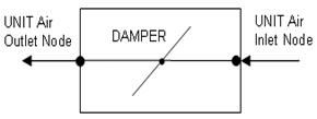
Figure 90. Single Duct VAV Heat and Cool NoReheat Schematic
Unique user-defined name for this Air Distribution Unit (ADU).
This alpha field defines the name of the schedule (ref: Schedule) that denotes whether or not this component is available to operate during a given time period. If a schedule value is greater than zero then the system is available to operate; otherwise, the system is unavailable for that time period.
This alpha field defines the name of the VAV damper air outlet node.
This alpha field defines the name of the air inlet node that connects the air splitter to the individual zone ADU.
This numeric field defines the design maximum volume flow rate (m3/sec) specified for this VAV ADU. This flow rate must be greater than 0 or can be autosized.
This numeric field defines the minimum air volume flow rate to the zone while the system is operating, specified as a fraction of the maximum air flow rate. The minimum zone fraction is normally specified to meet the minimum ventilation requirement for the occupants. This value must be between 0 and 1.
An IDF example is provided below:
AirTerminal:SingleDuct:VAV:HeatAndCool:NoReheat,
Zone 3 VAV System, !- Name of System
FanAndCoilAvailSched, !- System Availability schedule
Zone 3 Reheat Air Outlet Node, !- UNIT Air Outlet Node
Zone 3 VAV Inlet Node, !- UNIT Air Inlet Node
0.584, !- Maximum air flow rate {m3/s}
0.25; !- Zone Minimum Air Flow Fraction
HVAC,Average,VAV Terminal Damper Position []
This output is the damper position required to meet the zone load. This is the average value over the simulation timestep being reported. The damper position is defined as the terminal unit air mass flow rate divided by the terminal unit’s maximum air mass flow rate.
The series powered induction unit is an air system terminal unit that mixes varying amounts of secondary (recirculated) air and primary (conditioned supply) air to produce a fixed flow of air to a zone. The unit contains a small fan that acts to induce the secondary air and a heating coil for heating the mixed secondary and primary air. The fan runs at a constant volume flow rate whenever the unit is on (and the fan’s availability schedule is on or it is activated by an availability manager). The fan is downstream of the primary and secondary air inlets. The variable mixing is accomplished by a damper in the unit’s primary air supply inlet duct. This damper can move from fully open (100% primary air. 0% secondary air) to a minimum stop that is specified in the input description. At full cooling the damper will be fully open. At minimum cooling and for heating the damper will be at the minimum stop and the secondary air flow will be at its maximum.
The EnergyPlus model of the series PIU terminal unit is composed of three components: a zone mixer, a constant volume fan, and a heating coil (hot water, electric, or gas).
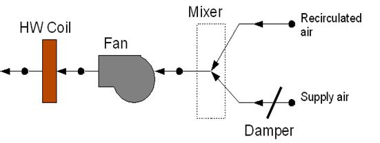
Figure 91. Series PIU Terminal Unit
A unique user assigned name for a particular series powered induction terminal unit. Any reference to this unit by another object will use this name.
The name of the schedule (ref: Schedule) that denotes whether the unit can run during a given hour. A schedule value greater than 0 (usually 1 is used) indicates that the unit can be on during the hour. A value less than or equal to 0 (usually 0 is used) denotes that the unit must be off for the hour.
The maximum volumetric air flow rate through the unit in cubic meters per second. Since this is a constant air volume unit, this is also the design, rated air flow rate of the unit.
The maximum volumetric air flow rate of primary air through the unit in cubic meters per second. This is the primary air flow rate at full cooling load when the primary air damper is fully open. Usually this quantity is the same as the total unit flow rate, but it can be less.
The minimum volumetric air flow rate of primary air through the unit expressed as a fraction of the maximum volumetric air flow rate of primary air. This input can be 0.0.
The name of the HVAC system node from which the unit draws its primary or supply air
The name of the HVAC system node from which the unit draws its secondary or recirculated air.
The name of the HVAC system node to which the unit sends its outlet air. This should be one of the inlet air nodes of the zone which is being served.
The name of the HVAC system node which is the inlet node of the unit’s heating coil. This is also the outlet node of the unit’s fan.
The name of an zone mixer component (object: AirLoopHVAC:ZoneMixer) which composes part of the unit. Note that some of the input for the mixer will duplicate input fields of the powered induction unit. One of the zone mixer inlet nodes should be the same as the supply air inlet node of the PIU; the other inlet node of the zone mixer should be the same as the secondary air inlet node of the PIU. The outlet node of the zone mixer should be the same as the inlet node of the PIU fan.
The name of a fan component which composes part of the unit. Note that the fan’s maximum flow rate should be the same as the maximum air flow rate of the PIU and the type of fan object must be Fan:ConstantVolume. The fan’s inlet node should be the same as the zone mixer’s outlet node. The fan’s outlet node should be the same as the heating coil’s air inlet node. The secondary fan will run according to the Availability Schedule specified in the Fan:ConstantVolume object, unless it is overridden by an availability manager (ref. AvailabilityManager:NightCycle and others).
The type of coil in the PIU. The valid choices are:
Coil:Heating:Water
Coil:Heating:Electric
Coil:Heating:Gas
Coil:Heating:Steam
In other words the PIU may have a hot water, gas, electric or steam reheat coil.
The name of the heating coil component which composes part of the unit. Note that the heating coil’s air inlet node is the same as the fan outlet node and the heating coil’s air outlet node is the same as the PIU outlet node.
The maximum hot water volumetric flow rate in m3/sec through the unit’s heating coil. If the heating coil is gas or electric this field should be blank.
The minimum hot water volumetric flow rate in m3/sec through the unit’s heating coil. If the heating coil is gas or electric this field should be blank.
The name of the HVAC system node which regulates the flow of hot water through the unit. This should be the same node as the water inlet node of the unit’s hot water coil. For gas or electric heating coils, this input should be blank.
The control tolerance for the unit heating output. The unit is controlled by matching the unit output to the zone demand. For units with water coils, the model must be numerically inverted to obtain a specified output. The convergence tolerance is the error tolerance used to terminate the numerical inversion procedure. Basically this is the fraction:

For gas or electric heating coils, this input should be left blank. The default is 0.001.
An IDF example:
AirTerminal:SingleDuct:SeriesPIU:Reheat,
Zone 1 SPIU ATU, ! Name of air terminal unit
FanAndCoilAvailSched, ! Availability schedule for series PIU ATU
0.47, ! Total volume flow rate through ATU
0.47, ! Maximum primary air flow rate through terminal unit
0.3, ! Minimum primary air flow rate (fraction of max)
Zone 1 PIU Pri Air Inlet Node, ! Air Terminal unit supply air inlet node
Zone 1 PIU Sec Air Inlet Node, ! Air Terminal unit secondary air inlet node
Zone 1 PIU Air Outlet Node, ! Air Terminal unit outlet node
Zone 1 Reheat Air Inlet Node, ! Reheat coil air inlet node (fan outlet node)
Zone 1 PIU Mixer, ! Air terminal unit mixer name
Zone 1 PIU Fan, ! Air terminal unit fan name
COIL:Heating:Water, ! type of air terminal unit reheat coil
Reheat Coil Zone 1, ! name of air terminal unit reheat coil
0.0013, ! Max Reheat Water Flow {Flow: m3/sec}
0.0, ! Min Reheat Water Flow {Flow: m3/sec}
Zone 1 Reheat Water Inlet Node, ! Control node
0.001; ! Convergence tolerance
HVAC,Average,PIU Heating Rate[W]
HVAC,Sum,PIU Heating Energy[J]
HVAC,Average,PIU Sensible Cooling Rate[W]
HVAC,Sum,PIU Sensible Cooling Energy[J]
This field reports the dry air heating addition rate of the series PIU terminal unit to the zone it is serving in Watts. This is determined by outlet and zone air conditions and the mass flow rate through the terminal unit.
This field reports the dry air heat addition of the series PIU terminal unit to the zone it is serving in Joules over the timestep being reported. This is determined by outlet and zone air conditions, the mass flow rate through the terminal unit, and the timestep.
This field reports the dry air sensible heat extraction rate of the series PIU terminal unit from the zone it is serving in Watts. This is determined by the outlet and zone conditions and the mass flow rate through the terminal unit.
This field reports the dry air sensible heat extraction of the series PIU terminal unit from the zone it is serving in Joules over the timestep being reported. This is determined by outlet and zone air conditions, the mass flow rate through the terminal unit, and the timestep.
The parallel powered induction unit is an air system terminal unit that mixes varying amounts of secondary (recirculated) air and primary (conditioned supply) air to produce a variable total flow of air to a zone. The unit contains a small fan that acts to induce the secondary air and a heating coil for heating the mixed secondary and primary air. The secondary and primary air streams enter the unit in parallel. The fan sits in the secondary air stream and runs only when the primary air flow is below the Fan On Flow Fraction and the fan’s availability schedule is on or it is activated by an availability manager. The primary air inlet contains a damper that can move from fully open (maximum primary air) to a minimum stop (minimum primary air).
At full cooling load the primary air damper is fully open and the fan is off. The primary air flow is at maximum and there is little or no secondary air flow. As the cooling load decreases, the primary air damper gradually closes and the secondary air flow remains close to zero. At some point, usually when the primary air flow has reached the minimum, the fan switches on and secondary air is induced. The heating coil will switch on as needed to meet any heating demand.
The EnergyPlus model of the parallel PIU terminal unit is composed of three components: a constant volume fan, a zone mixer, and a heating coil (hot water, electric, or gas).
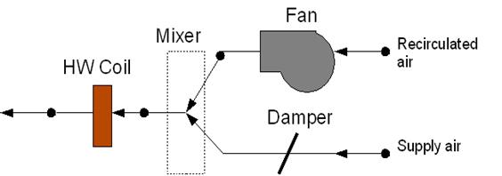
Figure 92. Parallel PIU Terminal Unit
A unique user assigned name for a particular parallel powered induction terminal unit. Any reference to this unit by another object will use this name.
The name of the schedule (ref: Schedule) that denotes whether the unit can run during a given hour. A schedule value greater than 0 (usually 1 is used) indicates that the unit can be on during the hour. A value less than or equal to 0 (usually 0 is used) denotes that the unit must be off for the hour.
The maximum volumetric air flow rate of primary air through the unit in cubic meters per second. This is the primary air flow rate at full cooling load when the primary air damper is fully open.
The maximum volumetric air flow rate of secondary air through the unit in cubic meters per second. This flow rate can be any amount but is commonly less than the maximum primary air flow rate.
The minimum volumetric air flow rate of primary air through the unit expressed as a fraction of the maximum volumetric air flow rate of primary air. This input can be 0.0.
The fraction of the primary air flow at which fan turns on. In the parallel PIU the fan operation is intermittent. If the primary air flow is above this fraction of the maximum, the fan is off. Otherwise the secondary fan will run according to the Availability Schedule specified in the Fan:ConstantVolume object (see Fan Name below), unless it is overridden by an availability manager (ref. AvailabilityManager:NightCycle and others).
The name of the HVAC system node from which the unit draws its primary or supply air
The name of the HVAC system node from which the unit draws its secondary or recirculated air.
The name of the HVAC system node to which the unit sends its outlet air. This should be one of the inlet air nodes of the zone which is being served.
The name of the HVAC system node which is the inlet node of the unit’s heating coil. This is also the outlet node of the unit’s zone mixer.
The name of an zone mixer component (object: AirLoopHVAC:ZoneMixer) which composes part of the unit. Note that some of the input for the mixer will duplicate input fields of the powered induction unit. One of the zone mixer inlet nodes should be the same as the supply air inlet node of the PIU; the other inlet node of the zone mixer should be the same as the air outlet node of the fan. The outlet node of the zone mixer should be the same as the inlet node of the heating coil.
The name of a fan component which composes part of the unit. Note that the fan’s maximum flow rate should be the same as the maximum secondary air flow rate of the PIU and the type of fan object must be Fan:ConstantVolume. The fan’s inlet node should be the same as the PIU secondary air inlet node. The fan’s outlet node should be the same as one of the zone mixer’s inlet nodes. When the primary air flow is below the Fan On Flow Fraction (above), the secondary fan will run according to the Availability Schedule specified in the Fan:ConstantVolume object, unless it is overridden by an availability manager (ref. AvailabilityManager:NightCycle and others).
The type of coil in the PIU. The valid choices are:
Coil:Heating:Water
Coil:Heating:Electric
Coil:Heating:Gas
Coil:Heating:Steam
In other words the PIU may have a hot water, gas, electric or steam reheat coil.
The name of the heating coil component which composes part of the unit. Note that the heating coil’s air inlet node is the same as the zone mixer’s outlet node and the heating coil’s air outlet node is the same as the PIU outlet node.
The maximum hot water volumetric flow rate in m3/sec through the unit’s heating coil. If the heating coil is gas or electric this field should be blank.
The minimum hot water volumetric flow rate in m3/sec through the unit’s heating coil. If the heating coil is gas or electric this field should be blank.
The name of the HVAC system node which regulates the flow of hot water through the unit. This should be the same node as the water inlet node of the unit’s hot water coil. For gas or electric heating coils, this input should be blank.
The control tolerance for the unit heating output. The unit is controlled by matching the unit output to the zone demand. For units with water coils, the model must be numerically inverted to obtain a specified output. The convergence tolerance is the error tolerance used to terminate the numerical inversion procedure. Basically this is the fraction:
For gas or electric heating coils, this input should be left blank. The default is 0.001.
An IDF example:
AirTerminal:SingleDuct:ParallelPIU:Reheat,
Zone 3 PPIU ATU, ! Name of air terminal unit
FanAndCoilAvailSched, ! Availability schedule for series PIU ATU
0.47, ! Maximum primary air flow rate through terminal unit
0.375, ! Maximum secondary air flow rate through the terminal unit
0.1, ! Minimum primary air flow rate (fraction of max)
0.1, ! fan on flow fraction
Zone 3 PIU Pri Air Inlet Node, ! Air Terminal unit supply air inlet node
Zone 3 PIU Sec Air Inlet Node, ! Air Terminal unit secondary air inlet node
Zone 3 PIU Air Outlet Node, ! Air Terminal unit outlet node
Zone 3 Reheat Air Inlet Node, ! Reheat coil air inlet node (fan outlet node)
Zone 3 PIU Mixer, ! Air terminal unit mixer name
Zone 3 PIU Fan, ! Air terminal unit fan name
Coil:Heating:Water, ! type of air terminal unit reheat coil
Reheat Coil Zone 3, ! name of air terminal unit reheat coil
0.0013, ! Max Reheat Water Flow {Flow: m3/sec}
0.0, ! Min Reheat Water Flow {Flow: m3/sec}
Zone 3 Reheat Water Inlet Node, ! Control node
0.001; ! Convergence tolerance
HVAC,Average,PIU Heating Rate[W]
HVAC,Sum,PIU Heating Energy[J]
HVAC,Average,PIU Sensible Cooling Rate[W]
HVAC,Sum,PIU Sensible Cooling Energy[J]
This field reports the dry air heating addition rate of the parallel PIU terminal unit to the zone it is serving in Watts. This is determined by outlet and zone air conditions and the mass flow rate through the terminal unit.
This field reports the dry air heat addition of the parallel PIU terminal unit to the zone it is serving in Joules over the timestep being reported. This is determined by outlet and zone air conditions, the mass flow rate through the terminal unit, and the timestep.
This field reports the sensible heat extraction rate of the parallel PIU terminal unit from the zone it is serving in Watts. This is determined by the outlet and zone conditions and the mass flow rate through the terminal unit.
This field reports the dry air sensible heat extraction of the parallel PIU terminal unit from the zone it is serving in Joules over the timestep being reported. This is determined by outlet and zone air conditions, the mass flow rate through the terminal unit, and the timestep.
The four pipe induction terminal unit provides local hot water heating or chilled water cooling of induced zone air which then mixes with centrally conditioned supply air. An air conditioning system consisting of these terminal units is effectively a mixed cental air / local hydronic system. The centrally conditioned air supplied to the induction terminal units is constant volume at quite high pressure. The central air is discharged through a nozzle in the terminal unit, inducing a flow of room air over a hydronic heating/cooling coil. The coil is connected either to a single inlet and outlet pipe (2 pipe unit) or to 2 inlets and 2 outlets (4 pipe unit). The heated or cooled induced air mixes with the centrally conditioned air before being discharged into the zone. The terminal units are usually expected to do only sensible cooling – any dehumidification is done by the central air conditioning system.
The EnergyPlus model of the four pipe induction terminal unit is a compound component consisting of a hot water heating coil, a chilled water cooling coil, and an air mixer. The unit has two inlet air streams: the centrally conditioned supply air and the induced air from the zone. The induced air passes first through the heating coil, then through the cooling coil and finally through the mixer. The central supply air goes directly into the mixer. The water flow through the hot or cold water coil is varied to meet the zone air conditioning requirement. Note that EnergyPlus models the four pipe induction terminal unit as having separate heating and cooling coils whereas real units have only a single coil used for both heating and cooling. Note also that the four pipe induction unit model can be used to model a two pipe unit by simply adjusting the heating and cooling coil schedules so that the heating coil is off when the cooling coil is on and vice versa.
A unique user assigned name for a particular four pipe induction terminal unit. Any reference to this unit by another object will use this name.
The name of the schedule (ref: Schedule) that denotes whether the unit can run during a given hour. A schedule value greater than 0 (usually 1 is used) indicates that the unit can be on during the hour. A value less than or equal to 0 (usually 0 is used) denotes that the unit must be off for the hour.
The maximum volumetric air flow rate discharged from the unit in cubic meters per second. Since this is a constant air volume unit, this is also the design, rated air flow rate of the unit. Note that this is the total discharge flow rate – including both central supply and induced air.
The ratio of induced air flow rate to primary supply air flow rate. The default is 1.0 –the supply air induces an equal amount of zone air.
The name of the HVAC system node from which the unit draws its primary or supply air
The name of the HVAC system node from which the unit draws its secondary or recirculated air. This should be the same node as one of the zone exhaust nodes.
The name of the HVAC system node to which the unit sends its outlet air. This should be one of the inlet air nodes of the zone which is being served.
The name of the HVAC system node which regulates the flow of hot water through the unit. This should be the same node as the water inlet node of the unit’s hot water coil.
The name of the HVAC system node which regulates the flow of cold water through the unit. This should be the same node as the water inlet node of the unit’s chilled water coil.
The type of heating coil in the terminal unit. The choices are:
Coil:Heating:Water
In other words the unit may have a hot water coil only.
The name of the heating coil component which composes part of the unit. Note that the heating coil’s air inlet node is the same as the terminal unit’s induced air inlet node. The heating coil’s air outlet node is the same as the cooling coil’s air inlet node.
The maximum hot water volumetric flow rate in m3/sec through the unit’s heating coil.
The minimum hot water volumetric flow rate in m3/sec through the unit’s heating coil.
The control tolerance for the unit heating output. The unit is controlled by matching the unit output to the zone demand. The model must be numerically inverted to obtain a specified output. The convergence tolerance is the error tolerance used to terminate the numerical inversion procedure. Basically this is the fraction:
The default is 0.001.
The type of cooling coil in the terminal unit. The choices are:
Coil:Cooling:Water
Coil:Cooling:Water:DetailedGeometry
In other words the unit must use only the water cooling coils.
The name of the cooling coil component which composes part of the unit. Note that the cooling coil’s air inlet node is the same as the heating coil’s air outlet node. The cooling coil’s air outlet node is the same as one of the zone mixer’s inlets.
The maximum cold water volumetric flow rate in m3/sec through the unit’s cooling coil.
The minimum cold water volumetric flow rate in m3/sec through the unit’s cooling coil.
The control tolerance for the unit cooling output. The unit is controlled by matching the unit output to the zone demand. The model must be numerically inverted to obtain a specified output. The convergence tolerance is the error tolerance used to terminate the numerical inversion procedure. Basically this is the fraction:

The default is 0.001.
The name of an zone mixer component (object: AirLoopHVAC:ZoneMixer) which composes part of the terminal unit. Note that some of the zone mixer’s inputs will duplicate some of the terminal units’s inputs. One of the zone mixer inlet nodes should be the same as the supply air inlet node of the terminal unit; the other inlet node of the zone mixer should be the same as the cooling coil air outlet node. The outlet node of the zone mixer should be the same as the outlet node of the terminal unit.
An IDF example:
AirTerminal:SingleDuct:ConstantVolume:FourPipeInduction,
SPACE2-1 FPIU, !- Name of System
ReheatCoilAvailSched, !- System Availability schedule
autosize, !- Maximum total air volume flow rate
1.0, !- Induction ratio
SPACE2-1 ATU Supply Node, !- Terminal unit supply air inlet node
SPACE2-1 ATU Induc Node, !- Terminal unit induced air inlet node
SPACE2-1 In Node, !- Terminal unit air outlet node
SPACE2-1 HW Coil Water In Node, !- Hot water control node
SPACE2-1 CW Coil Water In Node, !- Cold water control node
COIL:Heating:Water, !- Heating coil object
SPACE2-1 HW Coil, !- Heating coil name
autosize, !- Max hot water flow
0.0, !- Min hot water flow
0.001, !- Heating Convergence Tolerance
COIL:Cooling:Water, !- Cooling coil object
SPACE2-1 CW Coil, !- Cooling coil name
autosize, !- Max cold water flow
0.0, !- Min cold water flow
0.001, !- Cooling Convergence Tolerance
SPACE2-1 ATU Mixer; !- Zone mixer component name
COIL:Heating:Water,
SPACE2-1 HW Coil, !- Coil Name
ReheatCoilAvailSched, !- Available Schedule
autosize, !- UA of the Coil {W/K}
autosize, !- Max Water Flow Rate of Coil {m3/s}
SPACE2-1 HW Coil Water In Node, !- Coil_Water_Inlet_Node
SPACE2-1 HW Coil Water Out Node, !- Coil_Water_Outlet_Node
SPACE2-1 ATU Induc Node, !- Coil_Air_Inlet_Node
SPACE2-1 HW Coil Air Out Node; !- Coil_Air_Outlet_Node
COIL:Cooling:Water,
SPACE2-1 CW Coil, !- Coil Name
CWCoilAvailSched, !- Availability Schedule
autosize, !- UA of the Coil
autosize, !- Max Water Flow Rate of Coil
, !- Leaving Relative Humidity of Coil
SPACE2-1 CW Coil Water In Node, !- Coil_Water_Inlet_Node
SPACE2-1 CW Coil Water Out Node, !- Coil_Water_Outlet_Node
SPACE2-1 HW Coil Air Out Node, !- Coil_Air_Inlet_Node
SPACE2-1 CW Coil Air Out Node; !- Coil_Air_Outlet_Node
AirLoopHVAC:ZoneMixer,
SPACE2-1 ATU Mixer, !- Mixer Name
SPACE2-1 In Node, !- Outlet_Node
SPACE2-1 ATU Supply Node, !- Inlet_Node_1
SPACE2-1 CW Coil Air Out Node; !- Inlet_Node_2
There are no specific outputs for the four pipe induction terminal units.
The Cooled Beam system is a mixed air-hydronic system. A central, single-duct forced-air system supplies conditioned ventilation air to the zones. Sensible cooling is done by chilled water circulating through ceiling mounted cooled beam units. Chilled water flow rate through the cooled beam units is varied to meet the zone sensible cooling load. Any dehumidification is done by the central ventilation air system. Heating is usually accomplished with hot water radiators. Thermodynamically, the cooled beam system resembles the four-pipe induction unit.
To model a typical cooled beam system the user will need to define a conventional central constant volume forced air system. This system will normally be 100% outside air delivered at a fixed supply temperature (which could be reset by schedule or by outside air temperature). On the supply side of this air loop there will be the usual central AC equipment: outside air mixer, fan, heating and cooling coil. On the zone equipment (demand) side of the loop, the chilled beams will be represented as terminal units. Additional zone equipment (such as baseboard heaters) will be needed to handle heating loads.
Although the cooled beam equipment in a zone is treated by the program as a single terminal unit, the actual installation will have multiple beams in each zone. The program (in its sizing calculation for the system) figures out how many beams of what length are needed to meet the zone design load.
A unique user assigned name for a particular chilled beam unit. Any reference to this unit by another object will use this name.
The name of the schedule (ref: Schedule) that denotes whether the unit can run during a given hour. A schedule value greater than 0 (usually 1 is used) indicates that the unit can be on during the hour. A value less than or equal to 0 (usually 0 is used) denotes that the unit must be off for the hour.
Two types of units are modeled: Active or Passive. In the active unit, primary air is supplied through the beam, inducing some secondary zone air into contact with the coil. This unit acts as an active convector. The passive unit is simply a passive, finned convector. Primary air is supplied through a normal diffuser.
The name of the HVAC system node from which the unit draws its primary or supply air. Note that this field should be specified for both types of unit, even though supply air does not pass through the passive unit.
The name of the air node that connects this terminal unit to the zone. The will be the same as one of the zone inlet nodes. The name of this node must be entered even if the actual beams are passive and is not actually supplying air to the zone.
The name of the chilled water inlet node.
The name of the chilled water outlet node.
This is the air flow rate in cubic meters per second of the supply air entering the zone. This input would normally be autosized based on the ventilation requirement (see Zone Sizing).
The maximum chilled water flow rate (in cubic meters per second) for the unit. This input would normally be autosized based on the zone design load.
The number of individual cooled beam units in the zone. Normally this unit would be autocalculated by the program based upon the previous field and the nominal flow rate for a single beam unit (set by the program to 0.07 kg/s).
The length of an individual beam in meters. Normally this will be autocalculated by the program based upon the number of beam units and the zone design sensible cooling load. 1 to 4 meters is a typical length range.
The nominal or design inlet water temperature in degrees Celsius. The default is 15C.
The nominal or design outlet water temperature in degrees Celsius. The default is 17C.
The following inputs are parameters used to characterize the performance of the chilled beam units. Values for a given unit can be obtained from the manufacturer. The parameters are used in the following equations.
Pbeam = A·K·DT beam cooling output per unit length W/m
K=a·DTn1·vrn2·wn3 coil heat transfer coefficient W/(m2K)
vr=(qin/a0)·rair room air mass flow rate across coil kg/(m2s)
qin=K1·DTn+Kin·qpr room air volumetric flow rate across coil per
unit length m3/(s-m)
DT is the room air –water temperature difference (average water temperature is used) in degrees C.
w is the water velocity in m/s.
qpr is the supply air flow rate per unit length m3/(s-m)
Surface area on the air side of the beam per unit beam length. The units are square meters per meter. The default is 5.422. This is A in the above equations.
This is a in the above equations. The default is 15.3
This is n1 in the above equations. The default is 0.
This is n2 in the above equations. The default is 0.84.
This is n3 in the above equations. The default is 0.12.
This is a0 in the above equations. It is the free area of the coil in plan view (for the air flow) per unit beam length. The units are square meters per meter. The default is 0.171.
This is K1 in the above equations. The default is 0.005.
This is n in the above equations. The default is 0.4.
The coefficient of induction Kin in the above equations. The default is 2.0 for active beams and 0.0 for passive beams.
The water pipe inside diameter in meters. The default is 0.0145.
An example input is:
AirTerminal:SingleDuct:ConstantVolume:CooledBeam,
SPACE2-1 CB, !- Name
CWCoilAvailSched, !- Availability Schedule Name
Active, !- Cooled Beam Type
SPACE2-1 ATU Supply Node,!- Supply Air Inlet Node Name
SPACE2-1 In Node, !- Supply Air Outlet Node Name
SPACE2-1 CW Coil Water In Node, !- Chilled Water Inlet Node Name
SPACE2-1 CW Coil Water Out Node, !- Chilled Water Outlet Node Name
, !- Supply Air Volumetric Flow Rate
, !- Maximum Total Chilled Water Volumetric Flow Rate
, !- Number of Beams
, !- Beam Length
, !- Design Inlet Water Temperature
, !- Design Outlet Water temperature
, !- Coil Surface Area per Coil Length
, !- Model Parameter a
, !- Model Parameter n1
, !- Model Parameter n2
, !- Model Parameter n3
, !- Model Parameter a0
, !- Model Parameter K1
, !- Model Parameter n
, !- Coefficient of Induction Kin
; !- Leaving Pipe Inside Diameter
HVAC,Sum,Cooled Beam Cooling Energy [J]
HVAC,Average,Cooled Beam Cooling Rate[W]
HVAC,Sum,Cooled Beam Supply Air Cooling Energy [J]
HVAC,Average,Cooled Beam Supply Air Cooling Rate [W]
HVAC,Sum,Cooled Beam Supply Air Heating Energy [J]
HVAC,Average,Cooled Beam Supply Air Heating Rate [W]
Sensible cooling by the beams in the zone, exclusive of any cooling or heating done by the supply air.
Sensible cooling by the beams in the zone, exclusive of any cooling or heating done by the supply air.
Sensible cooling by the supply air to the zone, exclusive of any cooling done by the beams.
Sensible cooling by the supply air to the zone, exclusive of any cooling done by the beams.
Heating by the supply air to the zone, exclusive of any cooling done by the beams.
Heating by the supply air to the zone, exclusive of any cooling done by the beams.
The AirTerminal:DualDuct:ConstantVolume simulation or the typical Multizone is described by this Air Distribution Unit (ADU). Multizone systems condition all the air in a central apparatus and distribute it to the conditioned zones through two parallel ducts. One duct carries cold air and the other warm air, providing air sources for both heating and cooling at all times. In each conditioned zone, a mixing valve responsive to a room thermostat mixes the warm and cold air in proper proportions to satisfy the prevailing heating or cooling load of the space. The Multizone ADU is the specific component that leads to the zone containing the mixer and the mixing damper and then connecting to the zone. The total airflow to each room is kept constant while the proportion of hot air to cold air is adjusted to maintain the temperature in each zone at the desired level.
Unique name for the Multizone ADU.
Schedule that this component will operate or is available to operate.
The outlet node from the ADU to the zone.
The air-inlet node name that connects the hot air splitter to the individual zone ADU.
The air-inlet node name that connects the cold air splitter to the individual zone ADU.
The design constant volume flow rate (m3/sec) specified for that Multizone ADU.
An IDF example:
AirTerminal:DualDuct:ConstantVolume,
Zone2MixDamp, !- Name
FanAndCoilAvailSched, !- Availability Schedule
Zone 2 Dual Duct Outlet, !- Unit Air Outlet Node
Zone 2 Dual Duct Hot Inlet, !- Unit Hot Air Inlet Node
Zone 2 Dual Duct Cold Inlet, !- Unit Cold Air Inlet Node
0.36; !- Max Air Flow Rate {m3/s}
HVAC,Average,Dual Duct Terminal Cold Air Damper Position []
HVAC,Average,Dual Duct Terminal Hot Air Damper Position []
This output is the damper position of the cold air stream in a dual duct air terminal. This is the average value over the frequency being reported. The damper position is defined as the terminal unit cold air mass flow rate divided by the terminal unit’s maximum cold air mass flow rate.
This output is the damper position of the hot air stream in a dual duct air terminal. This is the average value over the frequency being reported. The damper position is defined as the terminal unit hot air mass flow rate divided by the terminal unit’s maximum hot air mass flow rate.
AirTerminal:DualDuct:VAV (i.e., Dual duct variable air volume (DDVAV)) systems are used to obtain zone temperature control by mixing the cold and warm air in various volume combinations. The fan is sized for the anticipated maximum coincident hot or cold volume, not the sum of the instantaneous peaks. This system has an advantage of a true single path VAV system, except for warm port leakage. When cold air is modulated for control before mixing, it operates similar to the VAV induction when mixing occurs without hot deck reheat. It is similar to a reheat system when mixing occurs while the hot deck is using the reheat coil. It uses more energy than a true VAV system, but less than a constant volume dual duct system.
Unique name for the AirTerminal:DualDuct:VAV Air Distribution Unit (ADU).
Schedule that this component will operate or is available to operate.
The outlet node from the ADU to the zone.
The air-inlet node name that connects the hot air splitter to the individual zone ADU.
The air-inlet node name that connects the cold air splitter to the individual zone ADU.
The design maximum volume flow rate (m3/sec) specified for DDVAV ADU.
The minimum flow rate to the zone while the system is operating, specified as a fraction of the Max Damper Air Flow Rate. The minimum zone fraction is normally specified to meet the minimum ventilation requirement for the occupants.
This alpha field specifies the name of a DesignSpecification:OutdoorAir object. When this field is used, the terminal unit will increase flow as needed to meet this outdoor air requirement. If Outdoor Air Flow per Person is non-zero, then the outdoor air requirement will be computed based on the current number of occupants in the zone. At no time will the supply air flow rate exceed the value for Maximum Air Flow Rate. If this field is blank, then the terminal unit will not be controlled for outdoor air flow. See documentation for the zone HVAC outdoor air object for further information (Ref DesignSpecification:OutdoorAir).
An IDF example:
AirTerminal:DualDuct:VAV,
Zone1MixDamp, !- Name
FanAndCoilAvailSched, !- Availability Schedule Name
Zone 1 Dual Duct Outlet, !- Air Outlet Node Name
Zone 1 Dual Duct Hot Inlet, !- Hot Air Inlet Node Name
Zone 1 Dual Duct Cold Inlet, !- Cold Air Inlet Node Name
autosize, !- Maximum Air Flow Rate {m3/s}
0.1, !- Zone Minimum Air Flow Fraction
ZoneMinOARequirements; !- Design Specification Outdoor Air Object Name
! Outdoor air specification should be consistent with Sizing:Zone object inputs.
DesignSpecification:OutdoorAir,
ZoneMinOARequirements, !- Name
Sum, !- Outdoor Air Method
0.00944, !- Outdoor Air Flow per Person {m3/s}
0.000508, !- Outdoor Air Flow per Zone Floor Area {m3/s-m2}
, !- Outdoor Air Flow per Zone
, !- Outdoor Air Flow Air Changes per Hour
Min OARequirements Sched; !- Outdoor Air Flow Rate Fraction Schedule Name
Schedule:Compact,
Min OARequirements Sched, !- Name
Any Number, !- Schedule Type Limits Name
Through: 12/31, !- Field 1
For: Weekdays SummerDesignDay WinterDesignDay, !- Field 2
Until: 24:00,1.0, !- Field 7
For: AllOtherDays, !- Field 9
Until: 24:00,0.25; !- Field 10
HVAC,Average,Dual Duct Terminal Cold Air Damper Position []
HVAC,Average,Dual Duct Terminal Hot Air Damper Position []
HVAC,Average,VAV Terminal Outdoor Air Flow Rate [m3/s]
This output is the damper position of the cold air stream in a dual duct air terminal. This is the average value over the frequency being reported. The damper position is defined as the terminal unit cold air mass flow rate divided by the terminal unit’s maximum cold air mass flow rate.
This output is the damper position of the hot air stream in a dual duct air terminal. This is the average value over the frequency being reported. The damper position is defined as the terminal unit hot air mass flow rate divided by the terminal unit’s maximum hot air mass flow rate.
This output is the amount of outdoor air entering the zone. This is the average value over the frequency being reported. The amount of outdoor air is defined as the terminal unit air volume flow rate multiplied by the fraction of outdoor air entering the air loop’s outdoor air system.
AirTerminal:DualDuct:VAV:OutdoorAir provides a model for a type of dual duct air system in which one duct provides outdoor air ventilation and the other provides VAV cooling. The Outdoor Air stream and the Recirculated Air stream are conditioned and supplied through separate air streams as part of a centralized dedicated outdoor air (DOAS) distribution system. The dual duct arrangement allows the ventilation air to be controlled separately using schedules or occupancy demand while the recirculated air is controlled to meet the dry-bulb zone temperature setpoint. The two airstreams remain decoupled until the terminal box where they are mixed. The terminal unit is meant for systems regulating outdoor air based only on demand control or code minimum settings and not on economizer operation.
This air terminal does not have heating coils and is not configured for conditions zones that need heat. Additional ZoneHVAC equipment, such as baseboards or fan coil units, are needed to provide heating to the zone when using this air terminal.
Although this air terminal is primarily for dual duct system, it is allowed to use just the outdoor air side in a single duct system. This can be useful for modeling single duct DOAS when the required volume of outdoor air varies over time.
Unique name for the AirTerminal:DualDuct:VAV:OutdoorAir Air Distribution Unit (ADU).
Schedule that this component will operate or is available to operate.
The outlet node of the terminal unit. This is the node leaving the unit and serving as the inlet to the zone. It is for the mixed flow leaving from both of the inlet node.
The inlet node of the Outdoor Air (OA) stream deck of the Dual Duct system.
The inlet node of the Recirculated Air (RA) stream deck of the Dual Duct system. This input is optional. If no node name is entered here, then the recirulation duct is disabled and the model functions as a single duct terminal and no second cooling deck is needed.
Max total airflow rate (in m3/s) at the terminal unit outlet including both the Outdoor Air stream and the Recirculated stream. Can be autosized based on the Design Outdoor Airflow Rate and the zone thermal cooling load. The autosized flow rate will be the sum of the maximum outdoor air requirement and the flow for cooling. When autosizing, this maximum and the individual inlet flow rate sizes are reported to the eio file.
This field specifies the name of a DesignSpecification:OutdoorAir object. This field is required for this object. The terminal unit will modulate the Outdoor Air stream to meet this outdoor air requirement. If Outdoor Air Flow per Person is applied, then the outdoor air required will be based on either the current number of occupants in the zone, as for demand controlled ventilation, or the design level of occupants depending on the setting in the next field.
This field specifies how the outdoor air ventilation rates are calculated when based on a rate per person. It can be either based on the current number of people as affected by time-varying occupancy schedules, or on the constant value for the maximum number of people. Enter the key CurrentOccupancy for the former and DesignOccupancy for the later.
An example input object follows.
AirTerminal:DualDuct:VAV:OutdoorAir,
Media_Center Dual Duct Box Component, !- Name
ALWAYS_ON, !- Availability Schedule Name
Media_Center Dual Duct Box Outlet Node Name, !- Air Outlet Node Name
Media_Center Dual Duct Box Inlet Node Name, !- Outdoor Air Inlet Node Name
RC Media_Center Dual Duct Box Inlet Node Name, !- Recirculated Air Inlet Node Name
AUTOSIZE, !- Maximum Terminal Air Flow Rate {m3/s}
Media_Center Dual Duct Box OA Design Spec, !- Design Specification Outdoor Air Object Name
CurrentOccupancy; !- Per Person Ventilation Rate Mode
DesignSpecification:OutdoorAir,
Media_Center Dual Duct Box OA Design Spec, !- Name
Sum, !- Outdoor Air Method
0.004719, !- Outdoor Air Flow per Person {m3/s-person}
0.00061, !- Outdoor Air Flow per Zone Floor Area {m3/s-m2}
0.0, !- Outdoor Air Flow per Zone {m3/s}
0.0, !- Outdoor Air Flow Air Changes per Hour
MinOA_Sched; !- Outdoor Air Flow Rate Fraction Schedule Name
Output:Variable,*,Dual Duct Outdoor Air Terminal Damper Position,hourly; !- HVAC Average []
Output:Variable,*,Dual Duct Recirculated Air Terminal Damper Position,hourly; !- HVAC Average []
Output:Variable,*,Dual Duct Outdoor Air Fraction,hourly; !- HVAC Average []
This output is the damper position of the outdoor air stream in a dual duct air terminal. This is the average value over the frequency being reported. The damper position is defined as the terminal unit outdoor air mass flow rate divided by the terminal unit’s maximum outdoor air mass flow rate. This output is dimensionless and ranges from 0.0 to 1.0.
This output is the damper position of the recirculated cool air stream in a dual duct air terminal. This is the average value over the frequency being reported. The damper position is defined as the terminal unit cool air mass flow rate divided by the terminal unit’s maximum cool air mass flow rate. This output is dimensionless and ranges from 0.0 to 1.0.
This output is the current fraction of outdoor air contained in the combined flow of aire entering the zone from the terminal unit. This is the average value over the frequency being reported. The outdoor air fraction is defined as the terminal unit outdoor air mass flow rate divided by the total air mass flow rate. This output is dimensionless and ranges from 0.0 to 1.0.
The simplest piece of zone equipment is the ZoneHVAC:IdealLoadsAirSystem component. ZoneHVAC:IdealLoadsAirSystem is used in situations where the user wishes to study the performance of a building without modeling a full HVAC system. In such a case, the Ideal Loads Air System is usually the sole conditioning component: the user does not need to specify air loops, water loops, etc. All that is needed for the ideal system are zone controls, zone equipment configurations, and the ideal loads system component.
This component can be operated with infinite or finite heating and cooling capacity. For either mode – infinite or limited capacity – the user can also specify on/off schedules for heating and cooling and outdoor air controls. There are also optional controls for dehumidification, humidification, economizer, and heat recovery. This component may be used in combination with other HVAC equipment serving the same zone.
This component can be thought of as an ideal unit that mixes air at the zone exhaust condition with the specified amount of outdoor air and then adds or removes heat and moisture at 100% efficiency in order to produce a supply air stream at the specified conditions. The energy required to condition the supply air is metered and reported as DistrictHeating and DistrictCooling.
Notes: The ideal loads system uses the zone return node or an optional zone exhaust node to extract air from the zone. Every zone served by an HVAC component must have a return air node, even though this node may not be connected to anything.
The ideal loads system was significantly expanded in version 7.0 (October 2011). As part of this upgrade, any change in the moisture content of the supply air stream results in a latent cooling (dehumidification) or latent heating (humidification) load which is metered as DistrictCooling and DistrictHeating energy consumption. Prior to version 7.0, when the ideal loads system was in heating mode, only the energy for sensible heating was metered. This results in significant changes in reported energy use compared to earlier versions, especially when using the ConstantSupplyHumidityRatio option for Humidification Control Type.
Older idf files which are transitioned to version 7.0 will automatically be set to use the ConstantSupplyHumidityRatio option for both dehumidification and humidification controls, because this is equivalent to the controls used in the older version of this system. However, the user should review all of the humidity control options and select the one which best reflects the goal of the simulation.
A unique user assigned name for each ideal loads air system component. This name is referenced in a ZoneHVAC:EquipmentList object.
This alpha field defines the name of the schedule (ref: Schedule) that denotes whether or not this component is available to operate during a given time period. If the schedule value is greater than zero then the system is available to operate; otherwise, the system is unavailable for that time period. If left blank, the system will always be available.
The name of the outlet air node of the ideal loads object. This should be the same as one of the zone air inlet nodes for the zone the ideal loads component is serving.
The name of the zone exhaust air node of the ideal loads object. This should be the same as one of the zone air exhaust nodes for the zone this component is serving. This node name is required if ZoneHVAC:IdealLoadsAirSystem is used in a zone which also has other forced air HVAC equipment. Otherwise this node name is optional but recommended.
The maximum air temperature (degrees C) of the air used for heating the zone. The default is 50C (122F).
The minimum air temperature (degrees C) of the air used for cooling the zone. The default is 13C (55.4F).
The maximum humidity ratio (kg of water per kg of dry air) of the hot supply air. The default is 0.0156 kg-H2O/kg-air which corresponds to a 20%RH at 50C (122F) dry bulb.
The minimum humidity ratio (kg of water per kg of dry air) of the cool supply air. The default is 0.0077 kg-H2O/kg-air which corresponds to a 10C (50F) dew point.
The input must be either LimitFlowRate, LimitCapacity, LimitFlowRateAndCapacity or NoLimit. LimitFlowRate means that the heating supply air flow rate will be limited to the value specified in the next input field. LimitCapacity means that the sensible heating capacity will be limited to the value specified in the Maximum Sensible Heating Capacity field. LimitFlowRateAndCapacity means that both flow rate and capacity will be limited. NoLimit (the default) means that there will not be any limit on the heating supply air flow rate or capacity and the subsequent two fields will be ignored.
The maximum heating supply air flow rate in cubic meters per second if heating limit is set to LimitFlowRate or LimitFlowRateAndCapacity . This field may be autosized. This field is ignored if heating limit is set to NoLimit or LimitCapacity. If blank, there is no limit.
The maximum allowed sensible heating capacity in Watts if Heating Limit is set to LimitCapacity or LimitFlowRateAndCapacity. This field may be autosized. If blank, there is no limit. If Heating Limit is set to NoLimit or LimitFlowRate, this field is ignored.
The input must be either LimitFlowRate, LimitCapacity, LimitFlowRateAndCapacity or NoLimit. LimitFlowrate means that the cooling supply air flow rate will be limited to the value specified in the next input field. LimitCapacity means that the total cooling capacity will be limited to the value specified in the Maximum Total Cooling Capacity field. LimitFlowRateAndCapacity means that both flow rate and capacity will be limited. NoLimit (the default) means that there will not be any limit on the cooling supply air flow rate or capacity and the subsequent two fields will be ignored.
The maximum cooling supply air flow rate in cubic meters per second if Cooling Limit is set to LimitFlowRate or LimitFlowRateAndCapacity. This field may be autosized. This field is ignored if cooling limit is set to NoLimit or LimitCapacity. If blank, there is no limit. If Cooling Limit is set to NoLimit, this field is ignored. This field is required if Outdoor Air Control Type is TemperatureEconomizer in order to establish an upper limit on outdoor air flow when the economizer is active.
The maximum allowed total (sensible plus latent) cooling capacity in Watts if Cooling Limit is set to LimitCapacity or LimitFlowRateAndCapacity. This field may be autosized. If blank, there is no limit. If Cooling Limit is set to NoLimit or LimitFlowRate, this field is ignored.
The name of a schedule (ref: Schedule) that denotes whether heating is available. A schedule value greater than 0 (usually 1 is used) indicates that heating and humidification are available. A value less than or equal to 0 (usually 0 is used) denotes that heating and humidification are not available. If blank, heating and humidification are always available.
The name of a schedule (ref: Schedule) that denotes whether cooling is available. A schedule value greater than 0 (usually 1 is used) indicates that cooling and dehumidification are available. A value less than or equal to 0 (usually 0 is used) denotes that cooling and dehumidification is not available. If blank, cooling and dehumidification are always available.
Select from ConstantSensibleHeatRatio, Humidistat, None, or ConstantSupplyHumidityRatio. ConstantSensibleHeatRatio (the default) means that the ideal loads system will be controlled to meet the sensible cooling load, and the latent cooling rate will be computed using a constant sensible heat ratio (SHR) (see next field). Humidistat means that there is a ZoneControl:Humidistat for this zone and the ideal loads system will attempt to meet the humidistat request (i.e. will dehumidify according to the Dehumidifying Relative Humidity Schedule in the ZoneControl:Humidistat object). None means that there is no dehumidification. ConstantSupplyHumidityRatio means that during cooling the supply air will always be at the Minimum Cooling Supply Humidity Ratio. For ConstantSensibleHeatRatio and Humidistat, if the mixed air humidity ratio is less than the target humidity ratio, then the mixed air humidity ratio will be used. For all options, the supply air humidity ratio will never be allowed to exceed saturation at the supply dry bulb temperature.
The selected dehumidification control type is always applied when the unit is in cooling mode. If the unit is in deadband mode (not actively heating the supply air) control type Humidistat will be active. If the unit is in heating mode, control type Humidistat will be active if the Humidification Control Type field below is set to Humidistat or None.
This allows the ideal loads system to heat and dehumidify at the same time.
When the Dehumidification Control Type is set to ConstantSensibleHeatRatio the ideal loads system will be controlled to meet the sensible cooling load, and the latent cooling rate will be computed using the value of Cooling Sensible Heat Ratio (SHR), where SHR = Sensible Cooling divided by Total Cooling (sensible plus latent). The default is 0.7. If Dehumidification Control Type is set to something other than ConstantSensibleHeatRatio then this field will be ignored.
Select from None, Humidistat, or ConstantSupplyHumidityRatio. None means that there is no humidification. Humidistat means that there is a ZoneControl:Humidistat for this zone and the ideal loads system will attempt to meet the humidistat request (i.e., humidify according to the Humidifying Relative Humidity Setpoint Schedule in the ZoneControl:Humidistat object). ConstantSupplyHumidityRatio means that during heating the supply air will always be at the Maximum Heating Supply Humidity Ratio. The default is None. For Humidistat, if the mixed air humidity ratio is greater than the target humidity ratio, then the mixed air humidity ratio will be used. For all options, the supply air humidity ratio will never be allowed to exceed saturation at the supply dry bulb temperature.
The selected humidification control type is always applied when the unit is in heating mode. If the unit is in deadband mode (not actively heating the supply air) control type Humidistat will be active. If the unit is in cooling mode, control type Humidistat will be active if the Dehumidification Control Type field above is set to Humidistat or None.
This allows the ideal loads system to cool and humidify at the same time.
This alpha field specifies the name of a DesignSpecification:OutdoorAir object which specifies the outdoor air requirements and schedule for this system. The outdoor air flow rate may also be affected by the next two fields, Demand Controlled Ventilation Type and Outdoor Air Economizer Type. If this field is blank, this system will have no outdoor air, and all outdoor air control and heat recovery options will be ignored..
This alpha field specifies the node name of the outdoor air inlet node. This node name is also specified in an OutdoorAir:Node or OutdoorAir:NodeList object. If this field is blank, a node name will be created internally.
This field, along with the Design Specification Outdoor Air Object (if used) specifies how the minimum outdoor air flow rate is calculated. The choices are: None, OccupancySchedule or CO2Setpoint. The default is None.
n None means that the design occupancy level will be used when computing the minimum outdoor air flow rate based on the inputs in the Design Specification Outdoor Air Object (see previous field).
n OccupancySchedule means that the current occupancy level will be used when computing the minimum outdoor air flow rate based on the inputs in the Design Specification Outdoor Air Object (see previous field).
n CO2Setpoint means that the design occupancy level will be used when computing the minimum outdoor air flow rate based on the inputs in the Design Specification Outdoor Air Object (see previous field). In addition, the minimum outdoor air flow rate may be increased if necessary to maintain the level of indoor air carbon dioxide at or below the setpoint defined in a ZoneControl:ContaminantController object.
This field specifies if there is an outdoor air economizer. The choices are: NoEconomizer, DifferentialDryBulb, or DifferentialEnthalpy. The default is NoEconomizer. DifferentialDryBulb and DifferentialEnthalpy mean that the economizer will increase the outdoor air flow rate above the minimum outdoor air flow (see the previous two fields) when there is a cooling load and the outdoor air temperature or enthalpy is below the zone exhaust air temperature or enthalpy. The DifferentialDryBulb and DifferentialEnthalpy options require that the Maximum Cooling Air Flow Rate be specified which will be used as the limit for maximum outdoor air flow rate.
Select from None, Sensible, or Enthalpy. None means that there is no heat recovery. Sensible means that there is sensible heat recovery whenever the zone exhaust air temperature is more favorable than the outdoor air temperature. Enthalpy means that there is latent and sensible heat recovery whenever the zone exhaust air enthalpy is more favorable than the outdoor air enthalpy.
The sensible heat recovery effectiveness, where effectiveness is defined as the change in supply temperature divided by the difference in entering supply and relief air temperatures. The default is 0.70.
The latent heat recovery effectiveness, where effectiveness is defined as the change in supply humidity ratio divided by the difference in entering supply and relief air humidity ratios. The default is 0.65.
An example of this object in an IDF is:
ZoneHVAC:IdealLoadsAirSystem,
Zone1 Ideal Loads System, !- Name
AlwaysOn, !- Availability Schedule Name
Zone1 Ideal Loads Supply Node, !- Zone Supply Air Node Name
Zone1 Ideal Loads Return Node, ! Zone Exhaust Air Node Name
50, !- Maximum Heating Supply Air Temperature {C}
13, !- Minimum Cooling Supply Air Temperature {C}
0.0156, !- Maximum Heating Supply Air Humidity Ratio {kg-H2O/kg-air}
0.0077, !- Minimum Cooling Supply Air Humidity Ratio {kg-H2O/kg-air}
NoLimit, !- Heating Limit
, !- Maximum Heating Air Flow Rate {m3/s}
, !- Maximum Sensible Heating Capacity {W}
NoLimit, !- Cooling Limit
, !- Maximum Cooling Air Flow Rate {m3/s}
, !- Maximum Total Cooling Capacity {W}
, !- Heating Availability Schedule Name
, !- Cooling Availability Schedule Name
ConstantSensibleHeatRatio, !- Dehumidification Control Type
0.7, !- Cooling Sensible Heat Ratio
None, !- Humidification Control Type
Office OA Specification, !- Design Specification Outdoor Air Object Name
Zone1 Ideal Loads OA Inlet Node, !- Outdoor Air Inlet Node Name
None, !- Demand Controlled Ventilation Type
NoEconomizer, !- Outdoor Air Economizer Type
Enthalpy, !- Heat Recovery Type
0.70, !- Sensible Heat Recovery Effectiveness
0.65; !- Latent Heat Recovery Effectiveness
HVAC,Sum,Ideal Loads Sensible Heating Energy [J]
HVAC,Sum,Ideal Loads Total Heating Energy [J]
HVAC,Sum,Ideal Loads Sensible Cooling Energy [J]
HVAC,Sum,Ideal Loads Latent Cooling Energy [J]
HVAC,Sum,Ideal Loads Total Cooling Energy [J]
HVAC,Sum,Ideal Loads Zone Sensible Heating Energy [J]
HVAC,Sum,Ideal Loads Zone Latent Heating Energy [J]
HVAC,Sum,Ideal Loads Zone Total Heating Energy [J]
HVAC,Sum,Ideal Loads Zone Sensible Cooling Energy [J]
HVAC,Sum,Ideal Loads Zone Latent Cooling Energy [J]
HVAC,Sum,Ideal Loads Zone Total Cooling Energy [J]
HVAC,Sum,Ideal Loads Outdoor Air Sensible Heating Energy [J]
HVAC,Sum,Ideal Loads Outdoor Air Latent Heating Energy [J]
HVAC,Sum,Ideal Loads Outdoor Air Total Heating Energy [J]
HVAC,Sum,Ideal Loads Outdoor Air Sensible Cooling Energy [J]
HVAC,Sum,Ideal Loads Outdoor Air Latent Cooling Energy [J]
HVAC,Sum,Ideal Loads Outdoor Air Total Cooling Energy [J]
HVAC,Sum,Ideal Loads Heat Recovery Sensible Heating Energy [J]
HVAC,Sum,Ideal Loads Heat Recovery Latent Heating Energy [J]
HVAC,Sum,Ideal Loads Heat Recovery Total Heating Energy [J]
HVAC,Sum,Ideal Loads Heat Recovery Sensible Cooling Energy [J]
HVAC,Sum,Ideal Loads Heat Recovery Latent Cooling Energy [J]
HVAC,Sum,Ideal Loads Heat Recovery Total Cooling Energy [J]
HVAC,Average,Ideal Loads Sensible Heating Rate [W]
HVAC,Average,Ideal Loads Latent Heating Rate [W]
HVAC,Average,Ideal Loads Total Heating Rate [W]
HVAC,Average,Ideal Loads Sensible Cooling Rate [W]
HVAC,Average,Ideal Loads Latent Cooling Rate [W]
HVAC,Average,Ideal Loads Total Cooling Rate [W]
HVAC,Average,Ideal Loads Zone Sensible Heating Rate [W]
HVAC,Average,Ideal Loads Zone Latent Heating Rate [W]
HVAC,Average,Ideal Loads Zone Total Heating Rate [W]
HVAC,Average,Ideal Loads Zone Sensible Cooling Rate [W]
HVAC,Average,Ideal Loads Zone Latent Cooling Rate [W]
HVAC,Average,Ideal Loads Zone Total Cooling Rate [W]
HVAC,Average,Ideal Loads Outdoor Air Sensible Heating Rate [W]
HVAC,Average,Ideal Loads Outdoor Air Latent Heating Rate [W]
HVAC,Average,Ideal Loads Outdoor Air Total Heating Rate [W]
HVAC,Average,Ideal Loads Outdoor Air Sensible Cooling Rate [W]
HVAC,Average,Ideal Loads Outdoor Air Latent Cooling Rate [W]
HVAC,Average,Ideal Loads Outdoor Air Total Cooling Rate [W]
HVAC,Average,Ideal Loads Heat Recovery Sensible Heating Rate [W]
HVAC,Average,Ideal Loads Heat Recovery Latent Heating Rate [W]
HVAC,Average,Ideal Loads Heat Recovery Total Heating Rate [W]
HVAC,Average,Ideal Loads Heat Recovery Sensible Cooling Rate [W]
HVAC,Average,Ideal Loads Heat Recovery Latent Cooling Rate [W]
HVAC,Average,Ideal Loads Heat Recovery Total Cooling Rate [W]
HVAC,Sum,Ideal Loads Time Economizer Active [hr]
HVAC,Sum,Ideal Loads Time Heat Recovery Active [hr]
All of the ZoneHVAC:IdealLoadsAirSystem loads and energy use are reported for Sensible Heating, Latent Heating, Total Heating, Sensible Cooling, Latent Cooling, and Total Cooling. To explain the relationship between the various outputs, Total Cooling Energy will be used.
Ideal Loads Total Cooling Energy is the district cooling energy consumed by the ideal loads system “cooling coil” to cool and dehumidify the supply air.
Ideal Loads Zone Total Cooling Energy is the total (sensible plus latent) cooling energy delivered to the zone. If there is no outdoor air, then Ideal Loads Total Cooling Energy = Ideal Loads Zone Total Cooling Energy.
Ideal Loads Outdoor Air Total Cooling Energy is the total (sensible plus latent) cooling energy required to cool the outdoor air to the zone exhaust air temperature and humidity ratio.
Ideal Loads Heat Recovery Total Cooling Energy is the total (sensible plus latent) cooling energy supplied by heat recovery. This offsets a portion of the Ideal Loads Outdoor Air Total Cooling Energy.
When the economizer is not active, these values are related by the following equation:
Ideal Loads Total Cooling Energy + Ideal Loads Heat Recovery Total Cooling Energy =
Ideal Loads Zone Total Cooling Energy+ Ideal Loads Outdoor Air Total Cooling Energy
The sensible heating energy (or rate) added to raise the temperature of the mixed air stream to the temperature of the supply air stream. This is the ideal “heating coil” load.
The latent heating energy (or rate) added to raise the humidity ratio of the mixed air stream to the temperature of the supply air stream. This is the ideal “humidifier” load.
The total (sensible and latent) heating energy (or rate) added to raise the mixed air stream to the temperature and humidity ratio of the supply air stream. Ideal Loads Total Heating Energy is metered as DistrictHeating energy.
The sensible cooling energy (or rate) removed to lower the temperature of the mixed air stream to the temperature of the supply air stream. This is the ideal “cooling coil” sensible load.
The latent cooling energy (or rate) removed to lower the humidity ratio of the mixed air stream to the temperature of the supply air stream. This is the ideal “cooling coil” latent load.
The total (sensible and latent) cooling energy (or rate) removed to lower the mixed air stream to the temperature and humidity ratio of the supply air stream. Ideal Loads Total Cooling Energy is metered as DistrictCooling energy. This is the ideal “cooling coil” total load.
The sensible heating energy (or rate) added to the zone.
The latent heating energy (or rate) added to the zone.
The total (sensible and latent) heating energy (or rate) added to the zone.
The sensible cooling energy (or rate) removed from the zone.
The latent cooling energy (or rate) removed from the zone.
The total (sensible and latent) cooling energy (or rate) removed from the zone.
The sensible heating energy (or rate) required to raise the temperature of the outdoor air to the zone exhaust air temperature. This value will be calculated only when heating is active.
The latent heating energy (or rate) required to raise the humidity ratio of the outdoor air to the zone exhaust air humidity ratio. This value will be calculated only when humidification is active.
The total (sensible and latent) heating energy (or rate) required to raise the temperature and humidity ratio of the outdoor air to the zone exhaust air humidity ratio. This value will be calculated only when heating or humidification is active.
The sensible cooling energy (or rate) required to lower (or raise) the temperature of the outdoor air to the zone exhaust air temperature. This value will be calculated only when cooling is active.
The latent cooling energy (or rate) required to lower (or raise) the humidity ratio of the outdoor air to the zone exhaust air humidity ratio. This will be calculated only when dehumidification is active.
The total (sensible and latent) cooling energy (or rate) required to lower the temperature and humidity ratio of the outdoor air to the zone exhaust air temperature and humidity ratio. This value will be calculated only when cooling or dehumidification is active.
The sensible heating energy (or rate) added to the outdoor air stream from heat recovery.
The latent heating energy (or rate) added to the outdoor air stream from heat recovery.
The total (sensible and latent) heating energy (or rate) added to the outdoor air stream from heat recovery.
The sensible cooling energy (or rate) removed from the outdoor air stream from heat recovery.
The latent cooling energy (or rate) removed from the outdoor air stream from heat recovery.
The total (sensible and latent) cooling energy (or rate) removed from the outdoor air stream from heat recovery.
Hours when the Ideal Loads economizer increased the outdoor air flow rate above the minimum.
Hours when the Ideal Loads heat recovery was actively heating or cooling the outdoor air stream.
What is a fan coil unit? Like many HVAC terms, “fan coil unit” is used rather loosely. Sometimes it is used for terminal units that would be better described as powered induction units. Carrier and others use the term for the room side of refrigerant-based split systems. Here we are modeling in-room forced-convection hydronic units. Typically these units are small (200 – 1200 cfm) and self-contained. They are mostly used in exterior zones, usually in hotels, apartments, or offices. They may be connected to ducted outside air, or have a direct outside air vent, but they do not have outside air economizers. Units with outside air economizers are marketed (in the United States) as unit ventilators. Unit ventilators are typically bigger than fan coils and are widely used in classrooms or other applications where ventilation is a priority. If a zonal unit with an outside economizer is desired, ZoneHVAC:UnitVentilator should be used.
The heating or cooling output of the unit ventilator is controlled by varying the air flow rate, the water flow rate, or both. Air flow rate can be controlled by cycling the fan on/off or with a variable speed fan drive. The most common setup is a two or three speed fan with the speed selected by hand. The fan then cycles on/off to control heating / cooling output. The controls are often a wall mounted thermostat with hand selection of heating/cooling and fan speed (off/low/medium/high). These controls may also be mounted on the unit
Carrier offers a retrofit VSD motor for fan coil units. It claims up to 45% energy savings from such a retrofit, as well as increased comfort and less noise compared to a cycling fan (fan coil fans ar typically noisy and inefficient). Some other manufacturers are also offering units with VSD fans. Variable speed fans appear to offer an easy way to significantly increase the efficiency of what have typically been very inefficient units.
EnergyPlus provides 4 capacity control methods for this unit: 1) multi-speed cycling fan with constant water flow rate; 2) constant speed continuous fan with variable water flow rate; 3) variable-speed fan with constant water flow rate; 4) variable-speed fan with variable water flow rate.
In EnergyPlus the fan coil units are modeled as compound components. That is, they are assembled from other components. Fan coils contain an outdoor air mixer, a fan, a heating coil and a cooling coil. These components are described elsewhere in this document. The fan coil input simply requires the names of these four components, which have to be described elsewhere in the input. The input also requires the name of an availability schedule, maximum airflow rate, outdoor airflow rate, and maximum and minimum hot and cold water volumetric flow rates. The unit is connected to the zone inlet and exhaust nodes and the outdoor air by specifying unit inlet, and outlet air node names and the outdoor air mixer object name. The outdoor air mixer child object provides the outdoor air and relief air nodes names. Note that the unit air inlet node should be the same as a zone exhaust node and the unit outlet node should be the same as a zone inlet node. The fan coil unit is connected to a hot water loop (demand side) through its hot water coil and to a chilled water loop (demand side) through its cooling coil.
Note that the type of fan component associated with the fan coil unit depends on the type of capacity control method chosen. For ConstantFanVariableFlow a Fan:OnOff or Fan:ConstantVolume should be used. For CyclingFan, a Fan:OnOff should be used. And for VariableFanVariableFlow or VariableFanConstantFlow a Fan:VariableVolume should be chosen.
Fan coil units can be 4-pipe or 2-pipe. For 4-pipe units there are 2 supply pipes and 2 return pipes. For 2-pipe units there is a single supply pipe and a single return pipe and the supply is switched between hot and chilled water depending on the season. We model 4-pipe units, but the 4-pipe model can be used to model 2-pipe units by using the coil availability schedules to make sure that either hot or chilled water is exclusively available.
A unique user assigned name for an instance of a Fan Coil unit. Any reference to this Fan Coil unit by another object will use this name.
The name of the schedule (ref: Schedule) that denotes whether the fan coil unit can run during a given hour. A schedule value greater than 0 (usually 1 is used) indicates that the unit can be on during the hour. A value less than or equal to 0 (usually 0 is used) denotes that the unit must be off for the hour.
Field: Capacity Control Method
This input denotes how the unit’s output is controlled in order to meet zone heating or cooling requirement. The choices are ConstantFanVariableFlow, CyclingFan, VariableFanVariableFlow or VariableFanConstantFlow. For ConstantFanVariableFlow, the fan speed is held constant to produce a fixed air flow rate whenever the unit is scheduled on. The hot water or chilled flow rate is varied so that the unit output matches the zone heating or cooling requirement. For CyclingFan, the fan speed is chosen so that the unit capacity is greater than or equal to the heating / cooling load and the fan is cycled to match unit output with the load. For VariableFanVariableFlow both air and water flow rates are varied to match the load. For VariableFanConstantFlow, the water flow rate is at full flow and the fan speed varies to meet the load.
The maximum volumetric airflow rate (m3/sec) through the fan coil unit. This is also the design, rated airflow rate of the unit.
This numerical field specifies the ratio of the low speed flow rate to the maximum supply air flow rate. Its value should be less than Medium Speed Supply Air Flow Ratio. If left blank, the default value is 0.33. Leave it blank if the capacity control method selected is not CyclingFan.
This numerical field specifies the ratio of the medium speed flow rate to the maximum supply air flow rate. Its value should be greater than the Low Speed Supply Air Flow Ratio but less than 1.If left blank, the default value is 0.66.Leave it blank if the capacity control method selected is not CyclingFan.
If the fan coil unit uses outdoor air, this field specifies the outdoor air volumetric flow rate (m3/sec). This flow rate should be less than or equal to the maximum airflow rate. A value of zero specifies no outdoor air.
The name of the HVAC system node from which the fan coil unit draws its indoor air. This should be one of zone exhaust nodes for the zone which the fan coil unit is serving.
The name of the HVAC system node to which the fan coil unit sends its outlet air. This should be one of the inlet air nodes of the zone which is being served.
This field specifies the type of outdoor air mixer used by this fan coil unit. The outdoor air mixer component is part of the fan coil compound object. The only available outdoor air mixer type is:
OutdoorAir:Mixer
The name of an outdoor air mixer component (object: OutdoorAir:Mixer) which composes part of the fan coil unit. Note that the return air node of the outdoor air mixer should be the same node as the air inlet node of the fan coil unit. In addition, the outdoor air mixer’s mixed air node should be the same as the inlet air node of the fan coil unit’s fan.
This field specifies the type of supply air fan object used by this fan coil. The supply air fan is part of the fan coil compound object. The only valid supply air fan types are:
Fan:OnOff
Fan:ConstantVolume
Fan:VariableVolume
The name of a fan component that composes part of the fan coil unit. Note that the fan’s maximum flow rate should be the same as the maximum airflow rate of the fan coil unit and the type of fan object should correspond to the capacity control method. Namely, for ConstantFanVariableFlow a Fan:OnOff or Fan:ConstantVolume should be used. For CyclingFan, a Fan:OnOff should be used. And for VariableFanVariableFlow or VariableFanConstantFlow a Fan:VariableVolume should be chosen. The fan’s inlet node should be the same as the outdoor air mixer’s mixed air node.
The fan’s outlet node should be the same as the cooling coil’s air inlet node.
The name of the cooling coil component that composes part of the fan coil unit. The cooling coil air inlet node should be the same as the fan outlet node. The cooling coil air outlet node should be the same as the heating coil air inlet node.
Only the following coil types can be used:
Coil:Cooling:Water
Coil:Cooling:Water:DetailedGeometry
CoilSystem:Cooling:Water:HeatExchangerAssisted
The maximum cold water volumetric flow rate (m3/sec) through the fan coil unit’s cooling coil.
The minimum cold water volumetric flow rate (m3/sec) through the fan coil unit’s cooling coil.
The convergence tolerance for the control of the unit cooling output. The unit is controlled by matching the unit output to the zone demand. For units with water coils, the model must be numerically inverted to obtain a specified output. The cooling convergence tolerance is the error tolerance used to terminate the numerical inversion procedure. Basically this is the fraction:

The name of the heating coil component that composes part of the fan coil unit. The heating coil air inlet node should be the same as the cooling coil outlet node. The heating coil air outlet node should be the same as the fan coil air outlet node.
Only the following coil type can be used:
Coil:Heating:Water
The maximum hot water volumetric flow rate (m3/sec) through the fan coil unit’s heating coil.
The minimum hot water volumetric flow rate (m3/sec) through the fan coil unit’s heating coil.
The convergence tolerance for the control of the unit heating output. The unit is controlled by matching the unit output to the zone demand. For units with water coils, the model must be numerically inverted to obtain a specified output. The heating convergence tolerance is the error tolerance used to terminate the numerical inversion procedure. Basically this is the fraction:

This field specifies the type of chilled water cooling coil to be modeled for this fan coil unit. Only the following coil types can be used:
Coil:Cooling:Water
Coil:Cooling:Water:DetailedGeometry
CoilSystem:Cooling:Water:HeatExchangerAssisted
The input requirements for these chilled water coil objects are described elsewhere in this document.
An example input for a fan coil unit, including its constituent components, is shown below.
ZoneHVAC:FourPipeFanCoil,
Zone1FanCoil, !- Name
FanAndCoilAvailSched, !- Availability Schedule Name
CyclingFan, !- Capacity Control Method
autosize, !- Maximum Supply Air Flow Rate {m3/s}
, !- Low Speed Supply Air Flow Ratio
, !- Medium Speed Supply Air Flow Ratio
autosize, !- Maximum Outdoor Air Flow Rate {m3/s}
OUTAIRFANCOILSCHEDULE, !- Outside Air Schedule Name
Zone1FanCoilAirInletNode,!- Air Inlet Node Name
Zone1FanCoilAirOutletNode, !- Air Outlet Node Name
OutdoorAir:Mixer, !- Outdoor Air Mixer Object Type
Zone1FanCoilOAMixer, !- Outdoor Air Mixer Name
Fan:OnOff, !- Supply Air Fan Object Type
Zone1FanCoilFan, !- Fan Name
Zone1FanCoilCoolingCoil, !- Cooling Coil Name
autosize, !- Maximum Cold Water Flow Rate {m3/s}
0.0, !- Minimum Cold Water Flow Rate {m3/s}
0.001, !- Cooling Convergence Tolerance
Zone1FanCoilHeatingCoil, !- Heating Coil Name
autosize, !- Maximum Hot Water Flow Rate {m3/s}
0.0, !- Minimum Hot Water Flow Rate {m3/s}
0.001, !- Heating Convergence Tolerance
Coil:Cooling:Water; !- Cooling Coil Object Type
OutdoorAir:Mixer,
Zone1FanCoilOAMixer, ! name
Zone1FanCoilOAMixerOutletNode, ! Mixed Air Node Name
Zone1FanCoilOAInNode, ! Outdoor Air Stream Node Name
Zone1FanCoilExhNode, ! Relief Air Stream Node Name
Zone1FanCoilAirInletNode; ! Return Air Stream Node Name
Fan:OnOff,
Zone1FanCoilFan, !- Name
FanAndCoilAvailSched, !- Availability Schedule Name
0.5, !- Fan Efficiency
75.0, !- Pressure Rise {Pa}
autosize, !- Maximum Flow Rate {m3/s}
0.9, !- Motor Efficiency
1.0, !- Motor In Airstream Fraction
Zone1FanCoilOAMixerOutletNode, !- Air Inlet Node Name
Zone1FanCoilFanOutletNode, !- Air Outlet Node Name
FanPowerRatioCurve, !- Fan Power Ratio Function of Speed Ratio Curve Name
FanEffRatioCurve; !- Fan Efficiency Ratio Function of Speed Ratio Curve Name
Coil:Cooling:Water,
Zone1FanCoilCoolingCoil, !- Name
FanAndCoilAvailSched, !- Availability Schedule Name
autosize, !- Design Water Flow Rate {m3/s}
autosize, !- Design Air Flow Rate {m3/s}
autosize, !- Design Inlet Water Temperature {C}
autosize, !- Design Inlet Air Temperature {C}
autosize, !- Design Outlet Air Temperature {C}
autosize, !- Design Inlet Air Humidity Ratio {kg-H2O/kg-air}
autosize, !- Design Outlet Air Humidity Ratio {kg-H2O/kg-air}
Zone1FanCoilChWInletNode,!- Water Inlet Node Name
Zone1FanCoilChWOutletNode, !- Water Outlet Node Name
Zone1FanCoilFanOutletNode, !- Air Inlet Node Name
Zone1FanCoilCCOutletNode,!- Air Outlet Node Name
SimpleAnalysis, !- Type of Analysis
CrossFlow; !- Heat Exchanger Configuration
Coil:Heating:Water,
Zone1FanCoilHeatingCoil, !- Name
FanAndCoilAvailSched, !- Availability Schedule Name
autosize, !- U-Factor Times Area Value {W/K}
autosize, !- Maximum Water Flow Rate {m3/s}
Zone1FanCoilHWInletNode, !- Water Inlet Node Name
Zone1FanCoilHWOutletNode,!- Water Outlet Node Name
Zone1FanCoilCCOutletNode,!- Air Inlet Node Name
Zone1FanCoilAirOutletNode, !- Air Outlet Node Name
UFactorTimesAreaAndDesignWaterFlowRate, !- Performance Input Method
autosize, !- Nominal Capacity {W}
82.2, !- Design Inlet Water Temperature {C}
16.6, !- Design Inlet Air Temperature {C}
71.1, !- Design Outlet Water Temperature {C}
32.2; !- Design Outlet Air Temperature {C}
Curve:Exponent,
FanPowerRatioCurve, !- Name
0.0, !- Coefficient1 Constant
1.0, !- Coefficient2 Constant
3.0, !- Coefficient3 Constant
0.0, !- Minimum Value of x
1.5, !- Maximum Value of x
0.01, !- Minimum Curve Output
1.5; !- Maximum Curve Output
Curve:Cubic,
FanEffRatioCurve, !- Name
0.33856828, !- Coefficient1 Constant
1.72644131, !- Coefficient2 x
-1.49280132, !- Coefficient3 x**2
0.42776208, !- Coefficient4 x**3
0.5, !- Minimum Value of x
1.5, !- Maximum Value of x
0.3, !- Minimum Curve Output
1.0; !- Maximum Curve Output
HVAC,Average,Fan Coil Heating Rate[W]
HVAC,Sum,Fan Coil Heating Energy[J]
HVAC,Average,Fan Coil Total Cooling Rate[W]
HVAC,Sum,Fan Coil Total Cooling Energy[J]
HVAC,Average,Fan Coil Sensible Cooling Rate[W]
HVAC,Sum,Fan Coil Sensible Cooling Energy[J]
HVAC,Average,Fan Coil Electric Power[W]
HVAC,Sum,Fan Coil Electric Consumption[J]
HVAC,Average,Fraction Of Timestep Fancoil is ON []
HVAC,Average,Fan Speed []
This field reports the dry air heating addition rate of the fan coil unit to the zone it is serving in Watts. This is determined by outlet and zone air conditions and the mass flow rate through the unit.
This field is the dry air heat addition of the fan coil unit to the zone it is serving in Joules over the timestep being reported. This is determined by outlet and zone air conditions, the mass flow rate through the unit, and the timestep.
This field is the total (sensible and latent) heat extraction rate of the fan coil unit from the zone it is serving in Watts. This is determined by the outlet and zone conditions and the mass flow rate through the unit.
This field is the total (sensible and latent) heat extraction of the fan coil unit from the zone it is serving in Joules over the timestep being reported. This is determined by outlet and zone air conditions, the mass flow rate through the unit, and the timestep.
This field reports the dry air sensible heat extraction rate of the fan coil unit from the zone it is serving in Watts. This is determined by the outlet and zone conditions and the mass flow rate through the unit.
This field is the dry air sensible heat extraction of the fan coil unit from the zone it is serving in Joules over the timestep being reported. This is determined by the outlet and zone conditions, the mass flow rate through the unit, and the timestep.
This field reports the electricity consumption rate of the fan coil unit in Watts.
This field is the electricity consumption of the fan coil unit in Joules over the timestep being reported.
This field is the fraction of the system timestep the fan coil unit is running for the CyclingFan capacity control method. This variable is defined only for the CyclingFan capacity control method.
This field is indicates the speed chosen for the fan in the CyclingFan capacity control method. A value of '0' means that the unit is off, '1' the fan is running at its low speed, '2' medium speed, and '3' high speed (maximum). This variable is defined only for the CyclingFan capacity control method.
When the capacity control method is VariableFanVariableFlow or VariableFanConstantFlow, this report variable reports the unit part load ratio (ratio of unit heating / cooling output to the maximum heating / cooling output). This variable is defined only for VariableFanVariableFlow or VariableFanConstantFlow capacity control methods.
Unit ventilators are zone equipment units which are assembled from other components. They contain a built-in outdoor air mixer, a fan, a heating coil, and a cooling coil. These components are described elsewhere in this document, except the built-in outdoor air mixer which is contained within the unit ventilator statement. The unit ventilator input simply requires the names of these other three components, which have to be described elsewhere in the input. The input also requires the name of an availability schedule, maximum airflow rate, outdoor air control information (control type and schedules), an outdoor airflow rate, and maximum and minimum hot and cold water mass flow rates. The unit is connected to the zone inlet and exhaust nodes and the outdoor air by specifying unit inlet, outlet, outdoor air and exhaust (relief) air node names. Note that the unit air inlet node should be the same as a zone exhaust node and the unit outlet node should be the same as a zone inlet node. In general, the unit ventilator input is very similar to the fan coil unit input, and the unit is connected to a hot water loop (demand side) through its hot water coil and to a chilled water loop (demand side) through its cooling coil.
The main difference between the fan coil and unit ventilator input is that the unit ventilator has a built-in outdoor air mixer with its own specialized controls. The outdoor air control type can be selected from one of the following options: “variable percent”, “fixed temperature” or “fixed amount”. In fixed temperature control, the amount of outdoor air is varied between the minimum outdoor air fraction (specified by a schedule) and 100% outdoor air to obtain a mixed air temperature as close as possible to the temperature schedule defined in the input. Variable percent control will also vary the amount of outdoor air between the minimum and maximum fractions (both specified in input by the user) to meet the load without the use of a coil if possible. In fixed amount control, the outdoor air flow rate is fixed to the specified value by the user. In this control strategy, the maximum outdoor air flow rate and schedule are automatically set to be equal to the minimum outdoor air flow rate and schedule. These control types are based on the 2004 ASHRAE Systems and Equipment Handbook (pp. 31.1-31.3) description of unit ventilator systems.
The unit is controlled to meet the zone (remaining) heating or cooling demand. If there is a heating demand, the cooling coil is off and the hot water flow through the heating coil is throttled to meet the demand. The hot water control node must be specified (same as the hot water coil inlet node). If there is a cooling demand from the zone, the hot water coil is off and the chilled water flow through the cooling coil is throttled to meet the load. The cooling coil control node must be specified (same as the cooling coil inlet node). Finally both heating and cooling require a convergence tolerance, which is the tolerance denoting how closely the fan coil unit will meet the heating or cooling load. The tolerance is always relative to the zone load.
Overall, control of the unit must consider the outdoor air. Here is a more detailed description of the overall unit control:
Off: Unit is schedule off or there is no load on it. All flow rates are set to zero and the temperatures are set to zone conditions (except for the outdoor air inlet). Outdoor air requirements will not override this condition.
Heating/No Coil/VariablePercent: The unit is on, there is a heating load, no heating coil is present or it has been scheduled off, and variable percent outdoor air control type has been specified. In this case, the variable percent outdoor air controls what happens with the outdoor air. If the outside temperature is greater than the return temperature, then the outdoor air is set to the maximum as defined by the user input. If the outdoor air temperature is less than the return temperature from the zone, then the outdoor air is set to the minimum outdoor air flow rate as defined by the user. Since a coil is not present to further condition the supply air, the zone simply receives whatever temperature air results from the outdoor air controls.
Heating/No Coil/FixedTemperature: The unit is on, there is a heating load, no heating coil is present or it has been scheduled off, and fixed temperature has been specified. The unit ventilator tries to use outdoor air as best as possible to meet the temperature goal. If it cannot meet this goal because the temperature goal is not between the zone return temperature and the outdoor air temperature, then the unit ventilator will either use the maximum or minimum outdoor air flow rate.
Heating/No Coil/FixedAmount: The unit is on, there is a heating load, no heating coil is present or it has been scheduled off, and fixed amount control has been specified. The unit ventilator fixes the outdoor air flow rate as defined by the user and sets the maximum and minimum outdoor air flow rate to be equal in order to avoid the variation of outdoor air flow rate between the maximum and minimum values. Since a coil is not present to further condition the supply air, the zone simply receives whatever temperature air results from the outdoor air controls.
Heating /With Coil/VariablePercent: The unit is on, there is a heating load, and variable percent control is specified. The outdoor air fraction is set to the minimum outdoor air fraction (schedule based), and the heating coil is activated. The heating coil attempts to meet the remaining load on the zone being served by the unit ventilator.
Heating /With Coil/FixedAmount: The unit is on, there is a heating load, a heating coil is present and is scheduled on, and fixed amount control has been specified. The unit ventilator fixes the outdoor air flow rate as defined by the user and sets the maximum and minimum outdoor air flow rate to be equal in order to avoid the variation of outdoor air flow rate between the maximum and minimum values. The heating coil then attempts to meet any remaining zone heating load.
Cooling/No Coil/VariablePercent: The unit is on, there is a cooling load, no coil is present or it has been scheduled off, and variable percent outdoor air control type has been specified. In this case, the variable percent outdoor air controls what happens with the outdoor air. If the outside temperature is greater than the return temperature, then the outdoor air is set to the minimum as defined by the user input. If the outdoor air temperature is less than the return temperature from the zone, then the outdoor air is set to the maximum outdoor air flow rate as defined by the user. This may be somewhat simplistic in that it could result in overcooling of the space. However, since a temperature goal was not established, this is the best that can be done by the simulation. Since a coil is not present to further condition the supply air, the zone simply receives whatever temperature air results from the outdoor air controls.
Cooling/No Coil/FixedTemperature: The unit is on, there is a cooling load, no cooling coil is present or it has been scheduled off, and fixed temperature has been specified. The unit ventilator tries to use outdoor air as best as possible to meet the temperature goal. If it cannot meet this goal because the temperature goal is not between the zone return temperature and the outdoor air temperature, then the unit ventilator will either use the maximum or minimum outdoor air flow rate in the same fashion as the variable percent outdoor air control.
Cooling/No Coil/FixedAmount: The unit is on, there is a cooling load, no cooling coil is present or it has been scheduled off, and fixed amount control has been specified. The unit ventilator fixes the outdoor air flow rate as defined by the user and sets the maximum and minimum outdoor air flow rate to be equal in order to avoid the variation of outdoor air flow rate between the maximum and minimum values. Since a coil is not present to further condition the supply air, the zone simply receives whatever temperature air results from the outside air controls.
Cooling/With Coil/VariablePercent: The unit is on, there is a cooling load, a coil is present and is scheduled on, and variable percent outdoor air control type has been specified. In this case, the percentage of outdoor air is set to the minimum flow outdoor air flow rate. The coil then attempts to meet any remaining zone load.
Cooling/With Coil/FixedTemperature: The unit is on, there is a cooling load, a cooling coil is present and is scheduled on, and fixed temperature has been specified. The unit ventilator tries to use outdoor air as best as possible to meet the temperature goal. If it cannot meet this goal because the temperature goal is not between the zone return temperature and the outdoor air temperature, then the unit ventilator will either use the maximum or minimum outdoor air flow rate in the same fashion as the fixed temperature outdoor air control for the “no coil” conditions. The cooling coil then attempts to meet any remaining zone load.
Cooling/With Coil/FixedAmount: The unit is on, there is a cooling load, a cooling coil is present and is scheduled on, and fixed amount control has been specified. The unit ventilator fixes the outdoor air flow rate as defined by the user and sets the maximum and minimum outdoor air flow rate to be equal in order to avoid the variation of outdoor air flow rate between the maximum and minimum values. The cooling coil then attempts to meet any remaining zone cooling load.
Note: the unit ventilator controls are strictly temperature based and do not factor humidity into the equation (not an enthalpy economy cycle but rather a simple return air economy cycle). In addition, temperature predictions are not strict energy balances here in the control routine though in the mixing routine an energy balance is preserved.
This field is simply the identifying name that distinguishes one particular unit ventilator from another in the input data file. Like all other names in EnergyPlus, it is assumed that this is a unique character string and that no other unit ventilators use this same name.
This field is a schedule name (ref: Schedule) that determines whether the unit ventilator is available to operate. The schedule is interpreted as a digital switch. If the schedule value of the unit ventilator availability schedule for a particular time frame is less than or equal to zero, then the unit ventilator is unavailable and will not operate. For any schedule value greater than zero, the unit ventilator is considered available and may operate, if necessary.
This field allows the user to enter the maximum volumetric flow rate of air through the unit ventilator system in m3/sec. This parameter should be some real number greater than zero.
This field allows the user to control how outdoor air is used in the unit ventilator system. The unit ventilator system described by this syntax has its own outdoor air handler. The three options for outdoor air control are “VariablePercent”, “FixedTemperature” and “FixedAmount”. Those keys are the only allowed choices for this parameter. In general, the variable percent control will attempt to vary the amount of outdoor air between some minimum and maximum schedules of fractions (see next two fields) to best meet the current heating or cooling load. The fixed temperature control will vary the amount of outdoor air between the minimum schedule (fraction of maximum, see next field) and 100% available outdoor air to come as close as possible to a desired mixed air temperature (see 2 fields down) that can be scheduled. The fixed amount control will fix the outdoor air flow rate as minimum outdoor air flow rate and schedule specified by the user and automatically set the maximum and minimum outside flow rate to be equal by ignoring the maximum outdoor air flow rate. More information on the controls and operation of the unit ventilator are given in the introductory section above.
This field allows the user to enter the minimum volumetric flow rate of outdoor air (in m3/sec) that will be brought in to the unit ventilator. The actual minimum outdoor air flow rate will be this number multiplied by the schedule value from the minimum outdoor air schedule. If “FixedAmount” type is selected as the outdoor air control strategy, the outdoor air flow rate will be fixed as this field and the unit ventilator will automatically set the maximum and minimum outside flow rate to be equal by ignoring the maximum outdoor air flow rate.
This field contains a schedule name (ref: Schedule) that should contain values for the minimum outdoor air used by the unit ventilator system for IAQ or other reasons. Note that if the unit ventilator is scheduled off or if there is no load sensed in the zone that the system will not operate even to achieve the minimum air fraction. However, if the system is operating, it will always bring in this fraction of the minimum air flow rate (see minimum air flow rate field above). If “FixedAmount” type is selected as the outdoor air control strategy, the actual outdoor air flow rate will be this number multiplied by the minimum outdoor air flow rate in the field above. The unit ventilator will automatically set the maximum and minimum outdoor air schedule to be equal by ignoring the maximum outdoor air schedule.
This field allows the user to enter the maximum volumetric flow rate of outdoor air that can be brought into the unit ventilator system in m3/sec. This parameter should be some real number greater than zero. Note that the value for this parameter may be less than the maximum air flow rate of the unit ventilator and this may affect the maximum fraction of outdoor air within the control strategy defined above. This parameter is an absolute maximum and will supercede any scheduled fraction of the unit ventilator maximum airflow rate. If “FixedAmount” type is selected as the outdoor air control strategy, this field will be ignored and be automatically set to be equal to the minimum outdoor air flow rate specified in the field above.
This field can have one of two meanings depending the type of control selected in the outdoor air control type parameter above. If “VariablePercent” or “FixedAmount” was selected, then this field is a schedule name (ref: Schedule) corresponding to a maximum air fraction schedule. Furthermore, if “FixedAmount” type is selected as the outdoor air control strategy, this field will be ignored and be automatically set to be equal to the minimum outdoor air fraction specified in the field below. Note that this is a fraction of the maximum airflow rate field (see parameter above) for the unit ventilator. If “FixedTemperature” control was selected, then this field is still a schedule name (ref: Schedule), but it corresponds to a schedule of mixed air temperatures that the outdoor air control will try to attain.
This field is a node name used to identify the node that serves as the inlet (air side) to the unit ventilator. In EnergyPlus, nodes represent points between components or at various points in the loops. In a unit ventilator, the air inlet node to the system will typically be the same node as a zone outlet node. While a node name may be referenced more than once in an input data file, each node must have a unique name.
This field is a node name used to identify the node that serves as the outlet (air side) to the unit ventilator. In EnergyPlus, nodes represent points between components or at various points in the loops. In a unit ventilator, the air outlet node from the system will typically be the same node as a zone inlet node. While a node name may be referenced more than once in an input data file, each node must have a unique name.
This field is a node name used to identify the node associated with fresh air brought into the unit ventilator from the outdoor environment. You should also have defined an OutdoorAir:Node object with the same name and assign it an optional height (above ground).
This field is a node name used to identify the node associated with air exhausted out of the unit ventilator to the outdoor environment. While from a simulation standpoint this name is arbitrary and not a “necessity”, assigning a name to this node allows the user to receive output on conditions at this node to verify the correct operation of the unit ventilator.
This field is a node name used to identify the node associated with the “mixed” air of the unit ventilator. These conditions are post-“mixing box” since they are the conditions of the fraction of return air combined with the outdoor air. Since this is a simple system, this can also be viewed as the conditions of the air being sent to the coils. While from a simulation standpoint this name is arbitrary and not a “necessity”, assigning a name to this node allows the user to receive output on conditions at this node to verify the correct operation of the unit ventilator.
This field specifies the type of supply air fan used by this unit ventilator. The supply air fan is part of the unit ventilator compound object. The only valid supply air fan types are:
Fan:ConstantVolume
Fan:VariableVolume
This field is the name of a fan (ref: Fan:ConstantVolume, Fan: VariableVolume) that is part of the unit ventilator system. This name links the unit ventilator to particular fan data entered elsewhere in the input data file. A fan name is required since it is the prime mover of air in the unit ventilator system.
This field allows the user to specify the coil operating options as one of the following options: None, Heating, Cooling or HeatingAndCooling. If None is selected, the unit ventilator does not have any coils, and any other input will be ignored. If either Heating or Cooling is selected, only a heating or cooling coil, respectively, is present. Thus, only four more inputs will be expected. If HeatingAndCooling is selected, both heating and cooling coil input must be entered, and the unit ventilator will have both a heating and a cooling coil.
This field is the type of coil that is used for heating in the unit ventilator system. It is used in conjunction with the heating coil name (see next field) to specify the heating coil present within the system. Allowable heating coil types are:
Coil:Heating:Water
Coil:Heating:Electric
Coil:Heating:Gas
Coil:Heating:Steam
This field is the name of the heating coil that is part of the unit ventilator system. It is assumed that there is always some sort of heating coil associated with a unit ventilator system. This name links the unit ventilator to particular heating coil data entered elsewhere in the input data file.
The control tolerance for the unit heating output. This field allows the user some control over how closely the heating coil will control the air side conditions. The relative size of this parameter relates directly to the closeness of the control. A very small value in this field will result in tight control and will probably result in larger numbers of iterations. A large value in this field will result in looser controls and could result in unsatisfactory fluctuations in supply conditions (that could in turn result in excessive iterations). Initial experience with this parameter lends to the recommendation of using 0.001 as a starting point. This field is ignored for gas and electric heating coils.
The unit is controlled by matching the unit output to the zone demand. For units with water coils, the model must be numerically inverted to obtain a specified output. The heating convergence tolerance is the error tolerance used to terminate the numerical inversion procedure. Basically this is the fraction:

This field is the type of coil that is used for cooling in the unit ventilator system. It is used in conjunction with the cooling coil name (see next field) to specify the cooling coil present within the system.
Only the following coil types can be used:
Coil:Cooling:Water
Coil:Cooling:Water:DetailedGeometry
CoilSystem:Cooling:Water:HeatExchangerAssisted
This field is the name of the cooling coil that is part of the unit ventilator system. This name links the unit ventilator to particular cooling coil data entered elsewhere in the input data file. Note that a cooling coil is not a required part of a unit ventilator system. If no cooling coil is present, the previous field may be followed by a semi-colon and the remaining parameters in this statement may be ignored.
The convergence tolerance for the unit cooling output. This field allows the user some control over how closely the cooling coil will control the air side conditions. The relative size of this parameter relates directly to the closeness of the control. A very small value in this field will result in tight control and will probably result in larger numbers of iterations. A large value in this field will result in looser controls and could result in unsatisfactory fluctuations in supply conditions (that could in turn result in excessive iterations). Initial experience with this parameter lends to the recommendation of using 0.001 as a starting point.
The unit is controlled by matching the unit output to the zone demand. For units with water coils, the model must be numerically inverted to obtain a specified output. The cooling convergence tolerance is the error tolerance used to terminate the numerical inversion procedure. Basically this is the fraction:

This optional input field is the name of an AvailabilityManagerAssignmentList object. An Availability Manager Assignment List is a list of Availability Managers giving both Availability Manager type and name. The availability managers in the list apply to this unit ventilator object’s fan. If the unit ventilator is available (per the Availability Schedule Name input field above) and this input field has a valid availability manager assignment list name, then the availability managers in the list determine when and if the fan of this unit ventilator object should be on or off.
An example input for a unit ventilator, including its constituent components, is shown below.
ZoneHVAC:UnitVentilator,
Zone1UnitVent, !- Name
UnitVentAvailability, !- Availability Schedule Name
0.84, !- Maximum Supply Air Flow Rate {m3/s}
VariablePercent, !- Outdoor Air Control Type
0.168, !- Minimum Outdoor Air Flow Rate {m3/s}
UnitVentMinOA, !- Minimum Outdoor Air Schedule Name
0.84, !- Maximum Outdoor Air Flow Rate {m3/s}
UnitVentMaxOA, !- Maximum Outdoor Air Fraction or Temperature Schedule Name
Zone1UnitVentAirInletNode, !- Air Inlet Node Name
Zone1UnitVentAirOutletNode, !- Air Outlet Node Name
Zone1UnitVentOAInNode, !- Outdoor Air Node Name
Zone1UnitVentExhNode, !- Exhaust Air Node Name
Zone1UnitVentOAMixerOutletNode, !- Mixed Air Node Name
Fan: ConstantVolume, !- Supply Air Fan Object Type
Zone1UnitVentFan, !- Fan Name
HeatingAndCooling, !- Coil Option
Coil:Heating:Water, !- Heating Coil Object Type
Zone1UnitVentHeatingCoil,!- Heating Coil Name
0.001, !- Heating Convergence Tolerance
Coil:Cooling:Water, !- Cooling Coil Object Type
Zone1UnitVentCoolingCoil,!- Cooling Coil Name
0.001; !- Cooling Convergence Tolerance
OutdoorAir:Node,
Zone1UnitVentOAInNode, !- Name
-1.0; !- Height Above Ground {m}
Fan:ConstantVolume,
Zone1UnitVentFan, !- Name
UnitVentAvailability, !- Availability Schedule Name
0.5, !- Fan Efficiency
75.0, !- Pressure Rise {Pa}
0.84, !- Maximum Flow Rate {m3/s}
0.9, !- Motor Efficiency
1.0, !- Motor In Airstream Fraction
Zone1UnitVentOAMixerOutletNode, !- Fan Inlet Node Name
Zone1UnitVentFanOutletNode; !- Fan Outlet Node Name
Coil:Cooling:Water,
Zone1UnitVentCoolingCoil,!- Name
FanAndCoilAvailSched, !- Availability Schedule Name
0.0010, !- Design Water Flow Rate {m3/s}
0.84, !- Design Air Flow Rate {m3/s}
6.67, !- Design Inlet Water Temperature {C}
30, !- Design Inlet Air Temperature {C}
12, !- Design Outlet Air Temperature {C}
0.013, !- Design Inlet Air Humidity Ratio {kg-H2O/kg-air}
0.008, !- Design Outlet Air Humidity Ratio {kg-H2O/kg-air}
Zone1UnitVentChWInletNode, !- Water Inlet Node Name
Zone1UnitVentChWOutletNode, !- Water Outlet Node Name
Zone1UnitVentFanOutletNode, !- Air Inlet Node Name
Zone1UnitVentCCOutletNode, !- Air Outlet Node Name
SimpleAnalysis, !- Type of Analysis
CrossFlow; !- Heat Exchanger Configuration
Coil:Heating:Water,
Zone1UnitVentHeatingCoil,!- Name
FanAndCoilAvailSched, !- Availability Schedule Name
400., !- U-Factor Times Area Value {W/K}
0.0005, !- Maximum Water Flow Rate {m3/s}
Zone1UnitVentHWInletNode,!- Water Inlet Node Name
Zone1UnitVentHWOutletNode, !- Water Outlet Node Name
Zone1UnitVentCCOutletNode, !- Air Inlet Node Name
Zone1UnitVentAirOutletNode, !- Air Outlet Node Name
UFactorTimesAreaAndDesignWaterFlowRate, !- Performance Input Method
autosize, !- Nominal Capacity {W}
82.2, !- Design Inlet Water Temperature {C}
16.6, !- Design Inlet Air Temperature {C}
71.1, !- Design Outlet Water Temperature {C}
32.2; !- Design Outlet Air Temperature {C}
HVAC,Average,Unit Ventilator Heating Rate[W]
HVAC,Sum,Unit Ventilator Heating Energy[J]
HVAC,Average,Unit Ventilator Total Cooling Rate[W]
HVAC,Sum,Unit Ventilator Total Cooling Energy[J]
HVAC,Average,Unit Ventilator Sensible Cooling Rate[W]
HVAC,Sum,Unit Ventilator Sensible Cooling Energy[J]
HVAC,Average,Unit Ventilator Fan Electric Power[W]
HVAC,Sum,Unit Ventilator Fan Electric Consumption[J]
HVAC,Average,Unit Ventilator Fan Availability Status[]
This field reports the heating output rate of the unit ventilator system to the zone it is serving in Watts. This is determined by outlet and zone air conditions and the mass flow rate through the unit ventilator.
This field is the heating output of the unit ventilator system to the zone it is serving in Joules over the timestep being reported. This is determined by outlet and zone air conditions, the mass flow rate through the unit ventilator, and the timestep.
This field reports the total cooling (sensible plus latent) output rate of the unit ventilator system to the zone it is serving in Watts. This is determined by outlet and zone air conditions and the mass flow rate through the unit ventilator.
This field is the total cooling (sensible plus latent) output of the unit ventilator system to the zone it is serving in Joules over the timestep being reported. This is determined by outlet and zone air conditions, the mass flow rate through the unit ventilator, and the timestep.
This field reports the sensible cooling output rate of the unit ventilator system to the zone it is serving in Watts. This is determined by outlet and zone air conditions and the mass flow rate through the unit ventilator.
This field is the sensible cooling output of the unit ventilator system to the zone it is serving in Joules over the timestep being reported. This is determined by outlet and zone air conditions, the mass flow rate through the unit ventilator, and the timestep.
This field reports the electric power consumption rate of the fan of the unit ventilator in Watts.
This field reports the electric power consumed by the fan of the unit ventilator over the timestep in Joules.
Unit Ventilator Fan Availability Status[]
This is the availability status of the unit ventilator fan. This status flag is a result of the calculations made by the Availability Manager(s) listed in an AvailabilityManagerAssignmentList object. This list is an optional input in the unit ventilator object. When a single availability manager is used in an Availability Manager Assignment List, this is also the availability status reported by the specific availability manager (Ref. AvailabilityManager:* Outputs). For multiple availability managers in an Availability Manager Assignment List, rules to determine fan availability status are described in the section ‘Group – System Availability Managers’. The control status outputs are represented using integers 0 through 3. These integers represent NoAction (0), ForceOff (1), CycleOn (2), and CycleOnZoneFansOnly (3). Since the status output is averaged, the output result may not correspond to the values described here when report variable frequencies other than detailed are used. Use the “detailed” reporting frequency (Ref. Report Variable) to view the availability status at each simulation timestep.
Unit heaters are zone equipment units which are assembled from other components and are a simplification of unit ventilators. They contain only a fan and a heating coil. These components are described elsewhere in this document. The unit heater input simply requires the names of these components, which have to be described elsewhere in the input. The input also requires the name of an availability schedule, maximum airflow rate, and maximum and minimum hot water volumetric flow rates. The unit is connected to the zone inlet and exhaust nodes by specifying unit inlet and outlet node names. Note that the unit air inlet node should be the same as a zone exhaust node and the unit outlet node should be the same as a zone inlet node.
While the control of the heating coil is similar to the fan coil units and the unit ventilator, the overall control of the unit heater is much different. There are four different modes in which a unit heat can operate based on the user input:
Off: Unit is schedule off. All flow rates are set to zero and the temperatures are set to zone conditions.
NoLoad OR Cooling/OnOff Fan Control: Unit is available, but there is no heating load. All flow rates are set to zero and the temperatures are set to zone conditions.
NoLoad OR Cooling/Continuous Fan Control: Unit is available and the fan is running (if it is scheduled to be available also). No heating is provided, only circulation via the fan running.
Heating: The unit is on/available and there is a heating load. The heating coil is modulated (constant fan speed) to meet the heating load.
Control of the heating coil and its flow rate is identical to the fan coil unit and unit ventilator.
This field is simply the identifying name that distinguishes one particular unit heater from another in the input data file. Like all other names in EnergyPlus, it is assumed that this is a unique character string and that no other unit heaters use this same name.
This field is a schedule name (ref: Schedule) that determines whether the unit heater is available to operate. The schedule is interpreted as a digital switch. If the schedule value of the unit heater availability schedule for a particular time frame is less than or equal to zero, then the unit heater is unavailable and will not operate. For any schedule value greater than zero, the unit heater is considered available and may operate.
This field is a node name used to identify the node that serves as the inlet (air side) to the unit heater. In EnergyPlus, nodes represent points between components or at various points in the loops. In a unit heater, the air inlet node to the system will typically be the same node as a zone outlet node. While a node name may be referenced more than once in an input data file, each node must have a unique name.
This field is a node name used to identify the node that serves as the outlet (air side) to the unit heater. In EnergyPlus, nodes represent points between components or at various points in the loops. In a unit heater, the air outlet node from the system will typically be the same node as a zone inlet node. While a node name may be referenced more than once in an input data file, each node must have a unique name.
This field specifies the type of supply air fan used by this unit heater. The supply air fan is part of the unit heater compound object. The only valid supply air fan types are:
Fan:ConstantVolume
Fan:VariableVolume
This field is the name of a fan (ref: Fan:ConstantVolume, Fan:VariableVolume) that is part of the unit heater system. This name links the unit heater to particular fan data entered elsewhere in the input data file. A fan name is required since it is the prime mover of air in the unit heater system.
This field allows the user to enter the maximum volumetric flow rate of air through the unit heater system in m3/s. This parameter should be some real number greater than zero.
This field allows the user to define how the unit heater will operate under “no load” or cooling conditions. The user may select from two options. If the “OnOff” control is selected, then the fan will not run unless there is a heating load. If the fan does not run, this effectively shuts the unit heater system off (there is no option to simply run the heating coil and allow natural convection to transfer heat from the unit to the zone). If the “Continuous” control is selected, then the fan will always run if the unit heater is available. This will produce air movement in the zone but also add some amount of heat to the energy balance since the fan will generate some heat. For more information on controlling the operation of the unit heater, see the general description given above.
This field is the type of coil that is used for heating in the unit heater system. It is used in conjunction with the heating coil name (see next field) to specify the heating coil present within the system. Allowable heating coil types are:
Coil:Heating:Water
Coil:Heating:Electric
Coil:Heating:Gas
Coil:Heating:Steam
This field is the name of the heating coil that is part of the unit heater system. It is assumed that there is always some sort of heating coil associated with a unit heater system. This name links the unit ventilator to particular heating coil data entered elsewhere in the input data file.
This field allows the user to enter a maximum volumetric flow rate of water through a water heating coil in m3/sec. This number should be some number greater than zero and greater than the minimum hot water volumetric flow rate (see next field). Note that this parameter has no meaning for either an electric or a gas heating coil.
This field allows the user to enter a minimum volumetric flow rate of water through a water heating coil in m3/sec. This number should be some number greater than zero and less than the maximum hot water volumetric flow rate (see previous field). Note that this parameter has no meaning for either an electric or a gas heating coil.
The convergence tolerance for the unit heating output. This field allows the user some control over how closely the heating coil will control the air side conditions. The relative size of this parameter relates directly to the closeness of the control. A very small value in this field will result in tight control and will probably result in larger numbers of iterations. A large value in this field will result in looser controls and could result in unsatisfactory fluctuations in supply conditions (that could in turn result in excessive iterations). Initial experience with this parameter lends to the recommendation of using 0.001 as a starting point. This field is ignored for gas and electric heating coils.
The unit is controlled by matching the unit output to the zone demand. For units with water coils, the model must be numerically inverted to obtain a specified output. The heating convergence tolerance is the error tolerance used to terminate the numerical inversion procedure. Basically this is the fraction:

This optional input field is the name of an AvailabilityManagerAssignmentList object. An Availability Manager Assignment List is a list of Availability Managers giving both Availability Manager type and name. The availability managers in the list apply to this unit heater object’s fan. If the unit heater is available (per the Availability Schedule Name input field above) and this input field has a valid availability manager assignment list name, then the availability managers in the list determine when and if the fan of this unit heater object should be on or off.
An example input for a unit heater, including its constituent components, is shown below.
ZoneHVAC:UnitHeater,
Zone1UnitHeat, !- Name
UnitHeatAvailability, !- Availability Schedule Name
Zone1UnitHeatAirInletNode, !- Air Inlet Node Name
Zone1UnitHeatAirOutletNode, !- Air Outlet Node Name
Fan: ConstantVolume, !- Supply Air Fan Object Type
Zone1UnitHeatFan, !- Fan Name
0.84, !- Maximum Supply Air Flow Rate {m3/s}
Continuous, !- Fan Control Type
Coil:Heating:Water, !- Heating Coil Object Type
Zone1UnitHeatHeatingCoil,!- Heating Coil Name
0.0005, !- Maximum Hot Water or Steam Flow Rate {m3/s}
0.0, !- Minimum Hot Water or Steam Flow Rate {m3/s}
0.001; !- Heating Convergence Tolerance
Fan:ConstantVolume,
Zone1UnitHeatFan, !- Name
UnitHeatAvailability, !- Availability Schedule Name
0.5, !- Fan Efficiency
75.0, !- Pressure Rise {Pa}
0.84, !- Maximum Flow Rate {m3/s}
0.9, !- Motor Efficiency
1.0, !- Motor In Airstream Fraction
Zone1UnitHeatAirInletNode, !- Fan Inlet Node Name
Zone1UnitHeatFanOutletNode; !- Fan Outlet Node Name
Coil:Heating:Water,
Zone1UnitHeatHeatingCoil,!- Name
FanAndCoilAvailSched, !- Availability Schedule Name
400., !- U-Factor Times Area Value {W/K}
0.0005, !- Maximum Water Flow Rate {m3/s}
Zone1UnitHeatHWInletNode,!- Water Inlet Node Name
Zone1UnitHeatHWOutletNode, !- Water Outlet Node Name
Zone1UnitHeatFanOutletNode, !- Air Inlet Node Name
Zone1UnitHeatAirOutletNode, !- Air Outlet Node Name
UFactorTimesAreaAndDesignWaterFlowRate, !- Performance Input Method
autosize, !- Nominal Capacity {W}
82.2, !- Design Inlet Water Temperature {C}
16.6, !- Design Inlet Air Temperature {C}
71.1, !- Design Outlet Water Temperature {C}
32.2; !- Design Outlet Air Temperature {C}
HVAC,Average,Unit Heater Heating Rate[W]
HVAC,Sum,Unit Heater Heating Energy[J]
HVAC,Average,Unit Heater Fan Electric Power[W]
HVAC,Sum,Unit Heater Fan Electric Consumption[J]
HVAC,Average, Unit Heater Fan Availability Status[]
This field reports the heating output rate of the unit heater system to the zone it is serving in Watts. This is determined by outlet and zone air conditions and the mass flow rate through the unit heater.
This field is the heating output of the unit heater system to the zone it is serving in Joules over the timestep being reported. This is determined by outlet and zone air conditions, the mass flow rate through the unit heater, and the timestep.
This field reports the electric power consumption rate of the fan of the unit heater in Watts.
This field reports the electric power consumed by the fan of the unit heater over the timestep in Joules.
Unit Heater Fan Availability Status
This is the availability status of the unit heater fan. This status flag is a result of the calculations made by the Availability Manager(s) listed in an AvailabilityManagerAssignmentList object. This list is an optional input in the unit heater object. When a single availability manager is used in an Availability Manager Assignment List, this is also the availability status reported by the specific availability manager (Ref. AvailabilityManager:* Outputs). For multiple availability managers in an Availability Manager Assignment List, rules to determine fan availability status are described in the section ‘Group – System Availability Managers’. The control status outputs are represented using integers 0 through 3. These integers represent NoAction (0), ForceOff (1), CycleOn (2), and CycleOnZoneFansOnly (3). Since the status output is averaged, the output result may not correspond to the values described here when report variable frequencies other than detailed are used. Use the “detailed” reporting frequency (Ref. Report Variable) to view the availability status at each simulation timestep.
The zone outdoor air unit (ZoneHVAC:OutdoorAirUnit) in EnergyPlus is intended to model dedicated outdoor air systems (DOAS) and other similar systems which aim to provide either additional outside air or some limited amount of sensible and/or latent conditioning. The zone outdoor air unit is a piece of zone equipment that can consist of a supply fan, an exhaust fan (optional), heating and cooling coils, and heat recovery. The outdoor air unit input simply requires information about flow rates, schedules, node names, and a list of component that are part of the unit. These components require additional input as per the requirements for these components. In addition, the input includes information about controls for the unit. It should be noted that the components that make up the zone outdoor air unit do not require additional controls or setpoints. The unit input defines how the unit outlet temperature is controlled as described below.
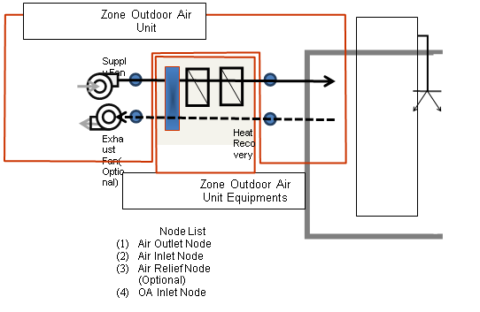
Figure 93. Zone Outdoor Air Unit Schematic
Zones may contain one or more zone outdoor air units. The user can choose to have each unit have its own exhaust fan or may choose to have only one unit have a exhaust fan that will handle the flow of all of the zone outdoor air units. Note that the user will need to account for any flow balance among the zone outdoor air units on the supply and exhaust sides.
The full input for zone outdoor air units is described below using a variety of fields.
This field is simply the identifying name that distinguishes one particular outdoor air unit from another in the input data file. Like all other names in EnergyPlus, it is assumed that this is a unique character string and that no other zone outdoor air units use this same name.
This field is a schedule name (ref: Schedule) that determines whether the zone outdoor air unit is available to operate. The schedule is interpreted as a digital switch. If the schedule value of the outdoor air unit availability schedule for a particular time frame is less than or equal to zero, then the outdoor air unit is unavailable and will not operate. For any schedule value greater than zero, the outdoor air unit is considered available and will operate at the supply and exhaust flow rates defined by input field described below.
This field is the name of the zone (Ref: Zone) in which the outdoor air unit is located and intended to affect. Zone outdoor air units impact only a single zone.
This field allows the user to enter the volumetric flow rate of outdoor air (in m3/sec) that will be brought in through the outdoor air unit. The actual outdoor air flow rate will be this number multiplied by the schedule value from the outdoor air schedule. This field is autosizable. When autosized, the unit’s outdoor air flow rate will match the minimum outdoor air requirements specified through the Sizing:Zone object.
This field contains a schedule name (ref: Schedule) that contains values for modifying the outdoor air flow rate. The supply air flow rate is the product of the outdoor air flow rate and the outdoor air schedule value for the time of interest. Note that if the outdoor air unit is scheduled off that the system will not operate regardless of the outdoor air schedule value. However, if the system is operating, it will always bring in this fraction of the outdoor air flow rate.
This field is the name of a fan (ref: Fan:ConstantVolume, Fan: VariableVolume) that is part of the zone outdoor air unit. This name links the outdoor air unit to particular fan data entered elsewhere in the input data file. A fan name is required since it is the prime mover of air in the outdoor air control unit.
This field has two choices: BlowThrough or DrawThrough. The first choice stands for “blow through fan”. It means that the unit consists of outdoor air node followed by a supply fan followed by the equipment that are part of the system. The second choice stands for “draw through fan”. It means that the supply fan placed at the end of supply air stream and supply fan outlet node is identified with the air outlet node. The fan “draws air through” the equipment system.
BlowThrough
DrawThrough
If the user does not select a fan placement type, DrawThrough is assumed as default by EnergyPlus.
This field is the name of a fan (ref: Fan:ConstantVolume, Fan: VariableVolume) that is part of the outdoor air unit. This name links the outdoor air unit to particular fan data entered elsewhere in the input data file. This field is optional.
This field allows the user to enter the volumetric flow rate of air (in m3/sec) that will be exhausted to the outdoors. The actual exhaust air flow rate will be this number multiplied by the schedule value from the exhaust air schedule. If the exhaust fan name is left blank, this field will be ignored and automatically set to be equal to zero.
This field contains a schedule name (ref: Schedule) that should contain values for modifying the exhaust air flow rate. The actual exhaust air flow rate equals the exhaust air flow rate input (previous field) multiplied by the exhaust air schedule value. If the exhaust fan name is left blank, this field will be ignored and automatically set to be equal to zero.
The unit control type field determines with conditions in the zone being served what the response of the zone outdoor air system will be. It is important to note that this only controls the temperature of the air being delivered to the space not whether or not the system will operate. There are two options for this field: Neutral or Temperature. Neutral control tries to have no energy impact on the zone by delivering air at the temperature of the zone. This allows air to be delivered to the zone without affecting the zone air heat balance and thus provides outside air without impacting any other system providing conditioning to this zone. The temperature control option will supply air to the zone based on the high and low air control temperature schedules (see next two fields). For temperature control, when the outside air temperature is less than the low air control temperature, the zone outdoor air unit will provide whatever heating is available from its components to achieve the low air temperature value. When the outside air temperature is above the high air control temperature, the zone outdoor air unit will provide whatever cooling is available from its components to achieve the high air temperature value. When the outdoor air temperature is between the high and low air control temperatures, the unit will simply provide air at whatever the outdoor air conditions are, modified by any fan heat added by the supply fan. In summary, the user must select from the following two options:
NeutralControl
TemperatureControl
If the user does not select a unit control type, NeutralControl is assumed as the default by EnergyPlus.
This field specifies the dry-bulb air temperature in degrees Celsius for the supply air temperature to the zone. When the outdoor air temperature or post-supply fan outlet temperature in the case of blow through is above the high air control temperature, a cooling coil, if available and specified by the user, is tuned on to conditioning the outdoor air to the high control temperature. This field only applies to zone outdoor air units that use Temperature Control (see previous field).
This field specifies the dry-bulb air temperature in degrees Celsius for the supply air temperature to the zone. When the outdoor air temperature or post-supply fan outlet temperature is below the low air control temperature, a heating coil, if available and specified by the user, is tuned on to conditioning the outdoor air to the low control temperature. This field only applies to zone outdoor air units that use Temperature Control (see two previous fields).
This field is a node name used to identify the node associated with fresh air brought into the outdoor air unit from the outdoor environment. It should also be defined in an OutdoorAir:Node object with the same name and assigned an optional height (above ground).
This field is a node name used to identify the node that serves as the outlet (air side) from the zone outdoor air unit. In EnergyPlus, nodes represent points between components or at various points in the loops. In an outdoor air unit, the air outlet node from the system will typically be the same node as a zone inlet node. While a node name may be referenced more than once in an input data file, each node must have a unique name.
This field is a node name used to identify the node that serves as the inlet (air side) to the exhaust side of the outdoor air unit. In EnergyPlus, nodes represent points between components or at various points in the loops. In an outdoor air unit, the air inlet node of the system will typically be the same node as a zone outlet node. While a node name may be referenced more than once in an input data file, each node must have a unique name.
This field is a node name used to identify the node that serves as the outlet (air side) of the supply fan for the zone outdoor air unit. In EnergyPlus, nodes represent points between components or at various points in the loops. While a node name may be referenced more than once in an input data file, each node must have a unique name.
This field is the name of an ZoneHVAC:OutdoorAirUnit:EquipmentList object. An ZoneHVAC:OutdoorAirUnit:EquipmentList is simply a list of components giving both component name and type. This equipment list specifies all the components that will be simulated in this unit. The order of the components in the list is significant: components are simulated sequentially in the order given in the Equipment List.
An example of this object defined in an input data file is shown below:
ZoneHVAC:OutdoorAirUnit,
Zone5DXOutAir, !- Name
OAUnitOASched, !- Availability Schedule Name
SPACE5-1, !- Zone Name
0.42, !- Outdoor Air Flow Rate {m3/s}
OAUnitOASched, !- Outdoor Air Schedule Name
Zone5OAUFan1, !- Supply Fan Name
BlowThrough, !- Supply Fan Placement
, !- Exhaust Fan Name
, !- Exhaust Air Flow Rate {m3/s}
, !- Exhaust Air Schedule Name
TemperatureControl, !- Unit Control Type
OAUHitemp2, !- High Air Control Temperature Schedule Name
OAULotemp2, !- Low Air Control Temperature Schedule Name
Zone5OAUOANode, !- Outdoor Air Node Name
Zone5OAUZoneInletNode, !- AirOutlet Node Name
Zone5OAUZoneOutletNode, !- AirInlet Node Name
Zone5OAUFanOutletNode, !- Supply FanOutlet Node Name
Zone5OAUEquip1; !- Outdoor Air Unit List Name
HVAC,Average,Outdoor Air Unit Heating Rate[W]
HVAC,Sum, Outdoor Air Unit Heating Energy[J]
HVAC,Average, Outdoor Air Unit Total Cooling Rate[W]
HVAC,Sum, Outdoor Air Unit Total Cooling Energy[J]
HVAC,Average, Outdoor Air Unit Sensible Cooling Rate[W]
HVAC,Sum, Outdoor Air Unit Sensible Cooling Energy[J]
HVAC,Average, Outdoor Air Unit Unit Fan Electric Power[W]
HVAC,Sum, Outdoor Air Unit Fan Electric Consumption[J]
HVAC,Average, Outdoor Air Unit Air Mass Flow Rate[kg/s]
This field reports the heating output rate of the outdoor air unit system to the zone it is serving in Watts. This is determined by outlet and zone air conditions and the mass flow rate through the zone outdoor air unit.
This field is the heating output of the outdoor air unit system to the zone it is serving in Joules over the timestep being reported. This is determined by outlet and zone air conditions, the mass flow rate through the zone outdoor air unit, and the time step.
This field reports the total cooling (sensible plus latent) output rate of the outdoor air unit system to the zone it is serving in Watts. This is determined by outlet and zone air conditions and the mass flow rate through the zone outdoor air unit.
This field is the total cooling (sensible plus latent) output of the outdoor air unit system to the zone it is serving in Joules over the timestep being reported. This is determined by outlet and zone air conditions, the mass flow rate through the zone outdoor air unit, and the time step.
This field reports the sensible cooling output rate of the outdoor air unit system to the zone it is serving in Watts. This is determined by outlet and zone air conditions and the mass flow rate through the zone outdoor air unit.
This field is the sensible cooling output of the outdoor air unit system to the zone it is serving in Joules over the timestep being reported. This is determined by outlet and zone air conditions, the mass flow rate through the zone outdoor air unit, and the time step.
This field reports the electric power consumption rate of the fan of the outdoor air unit in Watts.
This field reports the electric power consumed by the fan of the outdoor air unit over the time step in Joules.
This field reports the air mass flow rate of the zone outdoor air unit Outdoor Air Unit in kilograms per second.
This input syntax is used to specify the components in a zone outdoor air unit. The components will be simulated in the order in which they occur in this list.
The user designated unique name of an instance of a zone outdoor air unit equipment list.
After the identifying name, the list consists of up to 8 pairs of data items.
This field specifies the keyword for the type of component used.
This field is the unique name of the component specified in the previous field. This named object must appear in the IDF.
Note: If any of the components use the autosized option at the component level, input data for zone sizing purposes are required for the proper sizing of the components. Please refer to the Sizing:Zone object for more information.
An example from an IDF:
ZoneHVAC:OutdoorAirUnit:EquipmentList,
Zone5OAUEquip1, !- Name
Dehumidifier:Desiccant:NoFans, !- Component 1 Object Type
Z5Dessicant, !- Component 1 Name
HeatExchanger:AirToAir:FlatPlate, !- Component 2 Object Type
Zone5A2AHeat Recovery, !- Component 2 Name
AirLoopHVAC:UnitaryCoolOnly, !- Component 3 Object Type
DX Cooling Coil System 5,!- Component 3 Name
Coil:Heating:Electric, !- Component 4 Object Type
Zone5DESHCoil; !- Component 4 Name
The Window Air Conditioner is a unit of zone equipment made up of other components. Each window air conditioner consists of an outdoor air mixer, a fan, and a direct expansion (DX) cooling coil. These components are described elsewhere in this document. The input for a window air conditioner requires the names of these three pieces of equipment, which are then specified individually elsewhere in the input. The input for a window air conditioner also requires the name of an availability schedule, the maximum unit airflow rate, and the maximum outdoor airflow rate for the unit. The unit is connected to a zone by specifying an air inlet node, which must be the same as a zone exhaust node; and an air outlet node, which must be the same as a zone inlet node (ref. ZoneHVAC:EquipmentConnections).
A supply air fan operating mode schedule must also be specified. The supply air fan operating mode schedule value determines if the supply air fan can run continuously with the DX coil cycling on/off to match the zone cooling demand or the fan and DX coil can cycle on/off together to meet the cooling demand. The placement of the supply air fan, in relation to the DX coil, must also be specified (blow through or draw through). The cooling convergence tolerance is required, which is the tolerance denoting how closely the window air conditioner will meet the cooling load. The tolerance is always relative to the zone load (i.e., the unit will operate to meet the zone load to within the tolerance value times the zone load for each simulation timestep). Finally, the DX cooling coil type must be specified.
A unique user assigned name for an instance of a window air conditioner unit. Any reference to this window air conditioner by another object will use this name.
The name of the schedule (ref: Schedule) that denotes whether the window air conditioner unit can run during a given hour. A schedule value of 1 indicates that the unit can be on during the hour. A value of 0 denotes that the unit must be off for the hour.
The maximum volumetric airflow rate through the window air conditioner in cubic meters per second. Since the unit operates by cycling on/off, this is also the design, rated airflow rate of the unit.
If the window air conditioner uses outdoor air, this field specifies the outdoor air volumetric flow rate in cubic meters per second. This flow rate should be less than or equal to the maximum airflow rate. A value of zero specifies no outdoor air. Note that the outdoor airflow rate is fixed: it cannot change during the simulation
The name of the HVAC system node (see Node) from which the window air conditioner draws its indoor air. This should be one of the zone exhaust nodes for the zone which the window air conditioner is cooling.
The name of the HVAC system node (see Node) to which the window air conditioner sends its outlet air. This should be one of the inlet air nodes for the zone which is being cooled.
This field specifies the type of outdoor air mixer used by this window air conditioner unit. The outdoor air mixer component is part of the window air conditioner compound object. The only available outdoor air mixer type is:
OutdoorAir:Mixer
The name of an outdoor air mixer component which composes part of the window air conditioner unit. Note that the return air node of the outdoor air mixer should be the same node as the air inlet node of the window air conditioner. In addition, the outdoor air mixer’s mixed air node should be the same as the window air conditioner’s fan inlet air node (for blow through) or the air conditioner’s DX coil inlet node (for draw through)
This field specifies the type of supply air fan used by window air conditioner. The supply air fan is part of the window air conditioner compound object. The only valid supply air fan types are:
Fan:OnOff
Fan:ConstantVolume
The name of a constant volume fan component that composes part of the window air conditioner. Note that the fan’s maximum flow rate should be the same as the maximum airflow rate of the window air conditioner. A fan of type Fan:OnOff may be used with either cycling or continuous fan, and a fan of type Fan:ConstantVolume is used only with continuous fan (see Supply Air Fan Operating Mode Schedule field below). The fan’s inlet node should be the same as the outdoor air mixer’s mixed air node (for blow through) or the DX coil’s outlet node (for draw through). The fan’s outlet node should be the same as the DX coil’s air inlet node (for blow through) or the window air conditioner’s air outlet node (for draw through).
This field specifies the type of cooling coil to be modeled for this window air conditioner. The input requirements for these cooling coil objects are described elsewhere in this document. If the user wants to control the enhanced dehumidification performance of the Heat Exchanger Assisted coil type based on zone air humidity level, then the input file must include a humidistat object (ref. ZoneControl:Humidistat) for the zone being served by this air conditioner and a high humidity set point manager (ref. SetpointManager:SingleZone:Humidity:Maximum) with the high humidity set point placed on the outlet node of the heat exchanger assisted cooling coil. Only allowable coil types are:
Coil:Cooling:DX:SingleSpeed
CoilSystem:Cooling:DX:HeatExchangerAssisted
The name of a DX cooling coil component that composes part of the window air conditioner unit. The DX coil air inlet node should be the same as the fan outlet node (for blow through) or the outdoor air mixer’s mixed air node (for draw through). The DX coil air outlet node should be the same as the window air conditioner’s air outlet node (for blow through) or the fan’s inlet node (for draw through).
This alpha field specifies the name of the supply air fan operating mode schedule. The supply air fan operating mode may vary during the simulation based on time-of-day or with a change of season. Schedule values of 0 denote that the supply air fan and the heating or cooling coil cycle on and off together to meet the heating or cooling load (a.k.a. AUTO fan). Schedule values other than 0 denote that the supply air fan runs continuously while the heating or cooling coil cycles to meet the load. If this field is left blank, the model assumes the supply air fan cycles with the heating or cooling coil throughout the simulation.
This input field has two choices: BlowThrough or DrawThrough. The first choice stands for “blow through fan”. This means that the unit consists of an outdoor air mixer followed by a fan followed by a DX coil. The fan “blows through” the DX coil. The second choice stands for “draw through fan”. This means that the unit consists of an outdoor air mixer followed by a DX coil followed by a fan. The fan “draws air through” the coil.
This input field defines the convergence tolerance for the unit’s cooling output. This field allows the user some control over how closely the air conditioner will control the air-side conditions. The relative size of this parameter relates directly to the closeness of the control. A very small value in this field will result in tight control and will probably result in larger numbers of iterations. A large value in this field will result in looser controls and could result in unsatisfactory fluctuations in zone air temperature. Initial experience with this parameter lends to the recommendation of using 0.001 as the starting point.
The window air conditioner is controlled by matching its sensible (temperature) cooling output to the zone sensible load (demand). Because the performance of the DX coil is frequently non-linear, the air conditioner model must call the DX coil model several times (iterate) to determine the proper run time fraction to meet the zone load. The cooling convergence tolerance is the error tolerance used to terminate the iteration procedure when the following equation is satisfied:

The maximum number of iterations is limited, with a warning message generated if the above equation is not satisfied within the maximum number of iterations.
This optional input field is the name of an AvailabilityManagerAssignmentList object. An Availability Manager Assignment List is a list of Availability Managers giving both Availability Manager type and name. The availability managers in the list apply to this window air conditioner or object’s fan. If the window air conditioner is available (per the Availability Schedule Name input field above) and this input field has a valid availability manager assignment list name, then the availability managers in the list determine when and if the fan of this window air conditioner object should be on or off.
Following is an example input for the cycling window air conditioner, along with its constituent components.
ZoneHVAC:WindowAirConditioner,
Zone3WindAC, ! name of window AC unit
FanAndCoilAvailSched, ! Availability Schedule Name
0.6, ! Maximum Supply Air Flow Rate {m3/s}
0.05, ! Maximum Outdoor Air Flow Rate {m3/s}
Zone3WindACAirInletNode, ! Air Inlet Node Name
Zone3WindACAirOutletNode, ! Air Outlet Node Name
OutdoorAir:Mixer, ! Outdoor Air Mixer Object Type
Zone3WindACOAMixer, ! Outdoor Air Mixer Name
Fan:ConstantVolume, ! Supply Air Fan Object Type
Zone3WindACFan, ! Fan Name
Zone3WindACDXCoil, ! DX Cooling Coil Name
CyclingFanSch, ! Supply Air Fan Operation Mode Schedule Name
DrawThrough, ! Fan Placement
0.001, ! Cooling Convergence Tolerance
Coil:Cooling:DX:SingleSpeed; ! Cooling Coil Object Type
Schedule:Compact,
CyclingFanSch, !- Name
Fraction, !- ScheduleType
Through: 12/31, !- Complex Field #1
For: AllDays, !- Complex Field #2
Until: 24:00, !- Complex Field #7
0.0; !- Complex Field #8
OutdoorAir:Mixer,
Zone3WindACOAMixer, ! Name
Zone3WindACOAMixerOutletNode, ! Mixed Air Node Name
Zone3WindACOAInNode, ! Outdoor Air Stream Node Name
Zone3WindACExhNode, ! Relief Air Stream Node Name
Zone3WindACAirInletNode; ! Return Air Stream Node Name
Fan:ConstantVolume,
Zone3WindACFan, ! Name
FanAndCoilAvailSched, ! Availability Schedule Name
0.5, ! Fan Efficiency
75.0, ! Pressure Rise {Pa}
0.6, ! Maximum Flow Rate {m3/s}
0.9, ! Motor Efficiency
1.0, ! Motor In Airstream Fraction
Zone3WindACDXOutletNode, ! Air Inlet Node Name
Zone3WindACAirOutletNode; ! Air Outlet Node Name
Coil:Cooling:DX:SingleSpeed,
Zone3WindACDXCoil, !- Name
CoolingCoilAvailSched, !- Availability Schedule Name
autosize, !- Rated Total Cooling Capacity {W}
autosize, !- Rated Sensible Heat Ratio
3.0, !- Rated COP
autosize, !- Rated Air Flow Rate {m3/s}
Zone3WindACOAMixerOutletNode, !- Air Inlet Node Name
Zone3WindACDXOutletNode, !- Air Outlet Node Name
WindACCoolCapFT, !- Total Cooling Capacity Function of Temperature Curve Name
WindACCoolCapFFF, !- Total Cooling Capacity Function of Flow Fraction Curve Name
WindACEIRFT, !- Energy Input Ratio Function of Temperature Curve Name
WindACEIRFFF, !- Energy Input Ratio Function of Flow Fraction Curve Name
WindACPLFFPLR; !- Part Load Fraction Correlation Curve Name
HVAC,Average,Window AC Total Zone Cooling Rate[W]
HVAC,Sum,Window AC Total Zone Cooling Energy[J]
HVAC,Average,Window AC Sensible Zone Cooling Rate[W]
HVAC,Sum,Window AC Sensible Zone Cooling Energy[J]
HVAC,Average,Window AC Latent Zone Cooling Rate[W]
HVAC,Sum,Window AC Latent Zone Cooling Energy[J]
HVAC,Average,Window AC Electric Power[W]
HVAC,Sum,Window AC Electric Consumption[J]
HVAC,Average,Window AC Fan RunTime Fraction
HVAC,Average,Window AC Compressor RunTime Fraction
HVAC,Average,Window AC Fan Availability Status[]
This field is the total (sensible and latent) heat extraction rate of the window air conditioner unit from the zone it is serving in Watts. This is determined by the outlet and zone conditions and the mass flow rate through the unit.
This is the total (sensible and latent) heat extraction of the window air conditioner unit from the zone it is serving in Joules over the timestep being reported. This is determined by outlet and zone air conditions, the mass flow rate through the unit, and the timestep.
This field reports the moist air sensible heat extraction rate of the window air conditioner unit from the zone it is serving in Watts. This is determined by the outlet and zone conditions and the mass flow rate through the unit.
This field reports the moist air sensible heat extraction of the window air conditioner unit from the zone it is serving in Joules over the timestep being reported. This is determined by the outlet and zone conditions and the mass flow rate through the unit.
This output is the latent heat extraction rate of the window air conditioner unit from the zone it is serving in Watts. This is determined by the outlet and zone conditions and the mass flow rate through the unit.
This is the latent heat extraction of the window air conditioner unit from the zone it is serving in Joules over the timestep being reported. This is determined by the outlet and zone conditions and the mass flow rate through the unit.
This output is the electricity consumption rate of the window air conditioner unit in Watts. The consumption includes electricity used by the compressor and the fans (indoor supply air fan and the condenser fan).
This output is the electricity consumption of the window air conditioner unit in Joules for the time period being reported. The consumption includes electricity used by the compressor and the fans (indoor supply air fan and the condenser fan).
This is the fraction of the report timestep during which the fan had operated.
This is the fraction of the report timestep during which the DX unit compressor had operated.
Window AC Fan Availability Status
This is the availability status of the window air conditioner fan. This status flag is a result of the calculations made by the Availability Manager(s) listed in an AvailabilityManagerAssignmentList object. This list is an optional input in the window air conditioner object. When a single availability manager is used in an Availability Manager Assignment List, this is also the availability status reported by the specific availability manager (Ref. AvailabilityManager:* Outputs). For multiple availability managers in an Availability Manager Assignment List, rules to determine fan availability status are described in the section ‘Group – System Availability Managers’. The control status outputs are represented using integers 0 through 3. These integers represent NoAction (0), ForceOff (1), CycleOn (2), and CycleOnZoneFansOnly (3). Since the status output is averaged, the output result may not correspond to the values described here when report variable frequencies other than detailed are used. Use the “detailed” reporting frequency (Ref. Report Variable) to view the availability status at each simulation timestep.
The packaged terminal air conditioner (PTAC) is a compound object made up of other components. Each PTAC consists of an outdoor air mixer, direct expansion (DX) cooling coil, heating coil (gas, electric, hot water, or steam) and a supply air fan. While the figure below shows the PTAC with draw through fan placement, blow through fan placement can also be modeled by positioning the supply air fan between the outdoor air mixer and the DX cooling coil. The packaged terminal air conditioner coordinates the operation of these components and is modeled as a type of zone equipment (Ref. ZoneHVAC:EquipmentList and ZoneHVAC:EquipmentConnections).
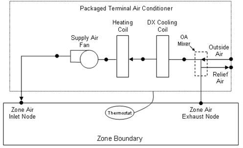
Figure 94. Schematic of a packaged terminal air conditioner with draw through fan placement
Links to the PTAC’s supply air fan, DX cooling coil, heating coil, and outdoor air mixer specifications are provided in the air conditioner’s input syntax. Additional inputs include supply and outdoor air flow rates during cooling operation, heating operation, and when neither cooling or heating is required. A description of each input field for the packaged terminal air conditioner compound object is provided below.
This alpha field defines a unique user-assigned name for an instance of a packaged terminal air conditioner. Any reference to this air conditioner by another object will use this name.
This alpha field defines the name of the schedule (ref: Schedule) that denotes whether the air conditioner operates during a given time period. A schedule value equal to 0 denotes that the air conditioner must be off for that time period. A value greater than 0 denotes that the air conditioner is available to operate during that time period. This schedule may be used to completely disable the air conditioner (all of its coils and the supply air fan) as required.
This alpha field defines the name of the HVAC system node from which the air conditioner draws its inlet air. This node name must be the name of a zone air exhaust node (Ref. ZoneHVAC:EquipmentConnections).
This alpha field defines the name of the HVAC system node to which the air conditioner sends its outlet air. This node name must be the name of a zone air inlet node (Ref. ZoneHVAC:EquipmentConnections).
This field specifies the type of outdoor air mixer used by this PTAC. The outdoor air mixer component is part of the PTAC unit. The only available outdoor air mixer type is:
OutdoorAir:Mixer
This alpha field defines the name of an outdoor air mixer component which composes part of the PTAC. The return air node of the outdoor air mixer should also be the same node as the air inlet node of the PTAC. Furthermore, the outdoor air mixer’s mixed air node should be the same as the PTAC’s fan inlet air node (for blow through fan placement) or the PTAC’s DX cooling coil inlet node (for draw through fan placement).
This numeric field defines the supply air flow rate leaving the air conditioner in cubic meters per second when the DX cooling coil is operating. Values must be greater than 0 or this field is autosizable.
This numeric field defines the supply air flow rate leaving the air conditioner in cubic meters per second when the heating coil is operating. Values must be greater than 0 or this field is autosizable.
This numeric field defines the supply air flow rate leaving the air conditioner in cubic meters per second when neither cooling nor heating is required (i.e., DX coil and heater are off but the supply air fan operates). This field is only used when the air conditioner’s supply air fan operating mode schedule specifies continuous fan operation. Values must be greater than or equal to zero, or this field is autosizable. If the air conditioner’s supply air fan operating mode schedule specifies continuous fan operation and this value is set to zero or this field is left blank, then the model assumes that the supply air flow rate when no cooling/heating is needed is equal to the supply air flow rate when the cooling or heating coil was last operating (for cooling operation or heating operation).
This numeric field defines the outdoor air flow rate through the air conditioner in cubic meters per second when the DX cooling coil is operating. Values must be greater than or equal to 0, or this field is autosizable. Note that the outdoor air flow rate during cooling operation is fixed; it cannot change during the simulation. In addition, the outdoor air flow rate during cooling operation cannot be greater than the air conditioner’s supply air volumetric flow rate during cooling operation.
This numeric field defines the outdoor air flow rate through the air conditioner in cubic meters per second when the heating coil is operating. Values must be greater than or equal to 0, or this field is autosizable. Note that the outdoor air flow rate during heating operation is fixed; it cannot change during the simulation. In addition, the outdoor air flow rate during heating operation cannot be greater than the air conditioner’s supply air volumetric flow rate during heating operation.
This numeric field defines the outdoor air flow rate through the air conditioner in cubic meters per second when neither cooling nor heating is required (i.e., cooling and heating coils are off but the supply air fan operates). Values must be greater than or equal to 0, or this field is autosizable. Note that the outdoor air flow rate when no cooling/heating is needed is fixed; it cannot change during the simulation. In addition, the outdoor air flow rate when no cooling/heating is needed cannot be greater than the air conditioner’s supply air volumetric flow rate when no cooling/heating is needed. This field is only used when the air conditioner’s supply air fan operating mode schedule specifies continuous fan operation. If the air conditioner’s supply air fan operating mode schedule specifies continuous fan operation and the field ‘Supply air volumetric flow rate when no cooling or heating is needed’ is set to zero or is left blank, then the model assumes that the outdoor air flow rate when no cooling/heating is needed is equal to the outdoor air flow rate when the cooling or heating coil was last operating (for cooling operation [i.e., Outdoor air Flow rate during cooling operation] or heating operation [i.e., Outdoor air flow rate during heating operation]) and this field is not used.
This alpha field defines the type of fan used by this PTAC. The only valid choices are Fan:OnOff and Fan:ConstantVolume. A fan of type Fan:OnOff is used with cycling fan operating mode, and a fan of type Fan:ConstantVolume is used with continuous fan operating mode (see Supply Air Fan Operating Mode Schedule field below). The input requirements for these fan objects are described elsewhere in this document.
The name of a constant volume fan component that composes part of the PTAC. Note that the fan’s maximum flow rate should be greater than or equal to the maximum supply air flow rate for the PTAC. The fan’s inlet node should be the same as the outdoor air mixer’s mixed air node (for blow through fan placement) or the heating coil’s outlet node (for draw through fan placement). The fan’s outlet node should be the same as the DX cooling coil’s air inlet node (for blow through fan placement) or the PTAC’s air outlet node (for draw through fan placement).
This alpha field defines the type of heating coil to be used by this PTAC. The input requirements for this heating coil object are described elsewhere in this document. Allowable heating coil types are:
Coil:Heating:Water
Coil:Heating:Electric
Coil:Heating:Gas
Coil:Heating:Steam
This alpha field defines the name of the heating coil used by this PTAC, and this name should match the name specified in the corresponding heating coil object.
This alpha field defines the type of DX cooling coil used by this PTAC. The input requirements for these DX cooling coil objects are described elsewhere in this document. Only allowable coil types are:
Coil:Cooling:DX:SingleSpeed
CoilSystem:Cooling:DX:HeatExchangerAssisted
This alpha field defines the name of the cooling coil used by this PTAC, and this name should match the name specified in the corresponding DX cooling coil object.
This alpha field has two choices: BlowThrough or DrawThrough. The first choice stands for “blow through fan”. This means that the unit consists of an outdoor air mixer followed by a fan followed by the DX cooling coil and heating coil. The fan “blows through” the DX cooling coil and the heating coil. The second choice stands for “draw through fan”. This means that the unit consists of an outdoor air mixer followed by the DX cooling coil and heating coil with the fan located at the outlet of the PTAC. The fan “draws air through” the DX cooling coil and the heating coil. If this field is left blank, the default is draw through.
Note: the packaged terminal air conditioner’s supply air fan, cooling coil and heating coil must be connected according to the configuration shown above (Figure 94) for the draw through fan configuration. The only other valid configuration is with a blow through fan placement, where the fan is located between the outdoor air mixer and the DX cooling coil.
This alpha field specifies the name of the supply air fan operating mode schedule. The supply air fan operating mode may vary during the simulation based on time-of-day or with a change of season. Schedule values of 0 denote that the supply air fan and the heating or cooling coil cycle on and off together to meet the heating or cooling load (a.k.a. AUTO fan). Schedule values other than 0 denote that the supply fan runs continuously while the heating or cooling coil cycles to meet the load.
This optional input field is the name of an AvailabilityManagerAssignmentList object. An Availability Manager Assignment List is a list of Availability Managers giving both Availability Manager type and name. The availability managers in the list apply to this packaged terminal air conditioner or object’s fan. If the packaged terminal air conditioner is available (per the Availability Schedule Name input field above) and this input field has a valid availability manager assignment list name, then the availability managers in the list determine when and if the fan of this packaged terminal air conditioner object should be on or off.
As shown in the example below, correct specification of the packaged terminal air conditioner requires the following objects in addition to the compound object itself:
1) Fan (Fan:OnOff or Fan:ConstantVolume)
2) DX cooling coil (Coil:Cooling:DX:SingleSpeed or CoilSystem:Cooling:DX:HeatExchangerAssisted)
3) Heating coil (Coil:Heating:Gas, Coil:Heating:Electric, Coil:Heating:Water, or Coil:Heating:Steam)
4) OutdoorAir:Mixer
ZoneHVAC:PackagedTerminalAirConditioner,
Zone2PTAC, !- Name
FanAndCoilAvailSched, !- Availability Schedule Name
Zone2PTACAirInletNode, !- Air Inlet Node Name
Zone2PTACAirOutletNode, !- Air Outlet Node Name
OutdoorAir:Mixer, !- Outdoor Air Mixer Object Type
Zone2PTACOAMixer, !- Outdoor Air Mixer Name
autosize, !- Supply Air Flow Rate During Cooling Operation {m3/s}
autosize, !- Supply Air Flow Rate During Heating Operation operation {m3/s}
autosize, !- Supply Air Flow Rate When No Cooling or Heating is Needed {m3/s}
autosize, !- Outdoor Air Flow Rate During Cooling Operation {m3/s}
autosize, !- Outdoor Air Flow Rate During Heating Operation {m3/s}
autosize, !- Outdoor Air Flow Rate When No Cooling or Heating is Needed {m3/s}
Fan:OnOff, !- Supply Air Fan Object Type
Zone2PTACFan, !- Supply Air Fan Name
Coil:Heating:Electric, !- Heating Coil Object Type
Zone2PTACHeatCoil, !- Heating Coil Name
Coil:Cooling:DX:SingleSpeed, !- Cooling Coil Object Type
Zone2PTACDXCoolCoil, !- Cooling Coil Name
BlowThrough, !- Fan Placement
SupplyFanSch; !- Supply Air Fan Operating Mode Schedule Name
Schedule:Compact,
SupplyFanSch, !- Name
Fraction, !- ScheduleType
Through: 12/31, !- Complex Field #1
For: AllDays, !- Complex Field #2
Until: 7:00, !- Complex Field #3
0.0, !- Complex Field #4
Until: 18:00, !- Complex Field #5
1.0, !- Complex Field #6
Until: 24:00, !- Complex Field #7
0.0; !- Complex Field #8
OutdoorAir:Mixer,
Zone2PTACOAMixer, !- Name
Zone2PTACOAMixerOutletNode, !- Mixed Air Node Name
Zone2PTACOAInNode, !- Outdoor Air Stream Node Name
Zone2PTACExhNode, !- Relief Air Stream Node Name
Zone2PTACAirInletNode; !- Return Air Stream Node Name
Fan:OnOff,
Zone2PTACFan, !- Name
FanAndCoilAvailSched, !- Availability Schedule Name
0.5, !- Fan Efficiency
75.0, !- Pressure Rise {Pa}
autosize, !- Maximum Flow Rate{m3/s}
0.9, !- Motor Efficiency
1.0, !- Motor In Airstream Fraction
Zone2PTACOAMixerOutletNode, !- Air Inlet Node Name
Zone2PTACFanOutletNode; !- Air Outlet Node Name
Coil:Cooling:DX:SingleSpeed,
Zone2PTACDXCoolCoil, !- Coil Name
CoolingCoilAvailSched, !- Availability Schedule Name
autosize, !- Rated Total Cooling Capacity (gross) {W}
autosize, !- Rated SHR
3.0, !- Rated COP
autosize, !- Rated Air Volume Flow Rate {m3/s}
Zone2PTACFanOutletNode, !- Coil Air Inlet Node
Zone2PTACCoolCoilOutletNode, !- Coil Air Outlet Node
HPACCoolCapFT, !- Total Cooling Capacity Modifier Curve (function of temperature)
HPACCoolCapFFF, !- Total Cooling Capacity Modifier Curve (function of flow fraction)
HPACEIRFT, !- Energy Input Ratio Modifier Curve (function of temperature)
HPACEIRFFF, !- Energy Input Ratio Modifier Curve (function of flow fraction)
HPACPLFFPLR; !- Part Load Fraction Correlation (function of part load ratio)
Coil:Heating:Electric,
Zone2PTACHeatCoil, !- Coil Name
HeatingCoilAvailSched, !- Availability Schedule Name
1.0, !- Efficiency
autosize, !- Nominal Capacity {W}
Zone2PTACCoolCoilOutletNode, !- Air Inlet Node Name
Zone2PTACAirOutletNode; !- Air Outlet Node Name
HVAC,Average,Packaged Terminal Air Conditioner Total Zone Heating Rate[W]
HVAC,Sum,Packaged Terminal Air Conditioner Total Zone Heating Energy[J]
HVAC,Average,Packaged Terminal Air Conditioner Total Zone Cooling Rate[W]
HVAC,Sum,Packaged Terminal Air Conditioner Total Zone Cooling Energy[J]
HVAC,Average,Packaged Terminal Air Conditioner Sensible Zone Heating Rate[W]
HVAC,Sum,Packaged Terminal Air Conditioner Sensible Zone Heating Energy[J]
HVAC,Average,Packaged Terminal Air Conditioner Sensible Zone Cooling Rate[W]
HVAC,Sum,Packaged Terminal Air Conditioner Sensible Zone Cooling Energy[J]
HVAC,Average,Packaged Terminal Air Conditioner Latent Zone Heating Rate[W]
HVAC,Sum,Packaged Terminal Air Conditioner Latent Zone Heating Energy[J]
HVAC,Average,Packaged Terminal Air Conditioner Latent Zone Cooling Rate[W]
HVAC,Sum,Packaged Terminal Air Conditioner Latent Zone Cooling Energy[J]
HVAC,Average,Packaged Terminal Air Conditioner Electric Power[W]
HVAC,Sum,Packaged Terminal Air Conditioner Electric Consumption[J]
HVAC,Average,Packaged Terminal Air Conditioner Fan Part-Load Ratio
HVAC,Average,Packaged Terminal Air Conditioner Part-Load Ratio
HVAC,Average,Packaged Terminal Air Conditioner Fan Availability Status[]
This output field is the total (enthalpy) heat addition rate of the packaged terminal air conditioner to the zone it is serving in Watts. This value is calculated using the enthalpy difference of the air conditioner outlet air and inlet air streams, and the air mass flow rate through the air conditioner. This value is calculated for each HVAC system timestep being simulated, and the results (enthalpy addition only) are averaged for the timestep being reported.
This output field is the total (enthalpy) heat addition of the packaged terminal air conditioner to the zone it is serving in Joules over the timestep being reported. This value is calculated using the enthalpy difference of the air conditioner outlet air and inlet air streams, the air mass flow rate through the air conditioner, and the HVAC simulation timestep. This value is calculated for each HVAC system timestep being simulated, and the results (enthalpy addition only) are summed for the timestep being reported.
This output field is the total (enthalpy) heat extraction rate of the packaged terminal air conditioner from the zone it is serving in Watts. This value is calculated using the enthalpy difference of the air conditioner outlet air and inlet air streams, and the air mass flow rate through the air conditioner. This value is calculated for each HVAC system timestep being simulated, and the results (enthalpy extraction only) are averaged for the timestep being reported.
This output field is the total (enthalpy) heat extraction of the packaged terminal air conditioner from the zone it is serving in Joules over the timestep being reported. This value is calculated using the enthalpy difference of the air conditioner outlet air and inlet air streams, the air mass flow rate through the air conditioner, and the HVAC simulation timestep. This value is calculated for each HVAC system timestep being simulated, and the results (enthalpy extraction only) are summed for the timestep being reported.
This output field is the sensible heat addition rate of the packaged terminal air conditioner to the zone it is serving in Watts. This value is calculated using the enthalpy difference of the air conditioner outlet air and inlet air streams at a constant humidity ratio, and the air mass flow rate through the air conditioner. This value is calculated for each HVAC system timestep being simulated, and the results (heating only) are averaged for the timestep being reported.
This output field is the sensible heat addition of the packaged terminal air conditioner to the zone it is serving in Joules over the timestep being reported. This value is calculated using the enthalpy difference of the air conditioner outlet air and inlet air streams at a constant humidity ratio, the air mass flow rate through the air conditioner, and the HVAC simulation timestep. This value is calculated for each HVAC system timestep being simulated, and the results (heating only) are summed for the timestep being reported.
This output field reports the moist air sensible heat extraction rate of the packaged terminal air conditioner from the zone it is serving in Watts. This value is calculated using the enthalpy difference of the air conditioner outlet air and inlet air streams at a constant humidity ratio, and the air mass flow rate through the air conditioner. This value is calculated for each HVAC system timestep being simulated, and the results (cooling only) are averaged for the timestep being reported.
This output field reports the moist air sensible heat extraction of the packaged terminal air conditioner from the zone it is serving in Joules over the timestep being reported. This value is calculated using the enthalpy difference of the air conditioner outlet air and inlet air streams at a constant humidity ratio, the air mass flow rate through the air conditioner, and the HVAC simulation timestep. This value is calculated for each HVAC system timestep being simulated, and the results (cooling only) are summed for the timestep being reported.
This output field is the latent heat addition (humidification) rate of the packaged terminal air conditioner to the zone it is serving in Watts. This value is calculated as the difference between the total energy rate and the sensible energy rate provided by the packaged terminal air conditioner. This value is calculated for each HVAC system timestep being simulated, and the results (latent heat addition only) are averaged for the timestep being reported.
This output field is the latent heat addition (humidification) of the packaged terminal air conditioner to the zone it is serving in Joules over the timestep being reported. This value is calculated as the difference between the total energy delivered to the zone and the sensible energy delivered to the zone by the packaged terminal air conditioner. This value is calculated for each HVAC system timestep being simulated, and the results (latent heat addition only) are summed for the timestep being reported.
This output field is the latent heat extraction (dehumidification) rate of the packaged terminal air conditioner from the zone it is serving in Watts. This value is calculated as the difference between the total energy rate and the sensible energy rate provided by the packaged terminal air conditioner. This value is calculated for each HVAC system timestep being simulated, and the results (latent heat extraction only) are averaged for the timestep being reported.
This output field is the latent heat extraction (dehumidification) of the packaged terminal air conditioner from the zone it is serving in Joules over the timestep being reported. This value is calculated as the difference between the total energy delivered to the zone and the sensible energy delivered to the zone by the packaged terminal air conditioner. This value is calculated for each HVAC system timestep being simulated, and the results (latent heat extraction only) are summed for the timestep being reported.
This output field is the electricity consumption rate of the packaged terminal air conditioner in Watts. The consumption includes electricity used by the compressor (including crankcase heater), fans (indoor supply air fan and the condenser fan), and the heating coil (includes electricity consumption rate for electric heating coil or parasitic electricity consumption rate for non-electric coils). This value is calculated for each HVAC system timestep being simulated, and the results are averaged for the timestep being reported.
This output field is the electricity consumption of the packaged terminal air conditioner in Joules for the time period being reported. The consumption includes electricity used by the compressor (including crankcase heater), fans (indoor supply air fan and the condenser fan), and the heating coil (includes electricity consumption for electric heating coil or parasitic electricity consumption for non-electric coils). This value is calculated for each HVAC system timestep being simulated, and the results are summed for the timestep being reported.
This output field is the part-load ratio of the fan. The fan part-load ratio is defined as the average supply air mass flow rate divided by the maximum supply air mass flow rate. The maximum supply air mass flow rate depends on whether heating, cooling, or no heating or cooling is required during the timestep. This value is calculated for each HVAC system timestep being simulated, and the results are averaged for the timestep being reported.
This output field is the part-load ratio used by the coils (cooling and heating). Part-load ratio is defined as the total coil load divided by the coil steady-state capacity. This value is calculated for each HVAC system timestep being simulated, and the results are averaged for the timestep being reported.
This is the availability status of the packaged terminal air conditioner fan. This status flag is a result of the calculations made by the Availability Manager(s) listed in an AvailabilityManagerAssignmentList object. This list is an optional input in the packaged terminal air conditioner object. When a single availability manager is used in an Availability Manager Assignment List, this is also the availability status reported by the specific availability manager (Ref. AvailabilityManager:* Outputs). For multiple availability managers in an Availability Manager Assignment List, rules to determine fan availability status are described in the section ‘Group – System Availability Managers’. The control status outputs are represented using integers 0 through 3. These integers represent NoAction (0), ForceOff (1), CycleOn (2), and CycleOnZoneFansOnly (3). Since the status output is averaged, the output result may not correspond to the values described here when report variable frequencies other than detailed are used. Use the “detailed” reporting frequency (Ref. Report Variable) to view the availability status at each simulation timestep.
The packaged terminal heat pump (PTHP) is a compound object made up of other components. Each PTHP consists of an outdoor air mixer, direct expansion (DX) cooling coil, DX heating coil, supply air fan, and a supplemental heating coil as shown in the figure below. These individual components are described elsewhere in this document. The packaged terminal heat pump coordinates the operation of these components and is modeled as a type of zone equipment (Ref. ZoneHVAC:EquipmentList and ZoneHVAC:EquipmentConnections).
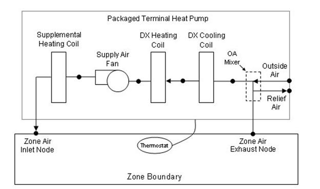
Figure 95. Schematic of a packaged terminal heat pump (draw through fan placement)
Links to the PTHP’s supply air fan, DX coils, supplemental heating coil, and outdoor air mixer specifications are provided in the heat pump’s input syntax. Additional inputs include supply and outdoor air flow rates during cooling operation, heating operation, and when neither cooling or heating is required. A description of each input field for the packaged terminal heat pump compound object is provided below.
This alpha field defines a unique user-assigned name for an instance of a packaged terminal heat pump. Any reference to this heat pump by another object will use this name.
This alpha field defines the name of the schedule (ref: Schedule) that denotes whether the heat pump operates during a given time period. A schedule value equal to 0 denotes that the heat pump must be off for that time period. A value greater than 0 denotes that the heat pump is available to operate during that time period. This schedule may be used to completely disable the heat pump (all of its coils and the supply air fan) as required.
This alpha field defines the name of the HVAC system node from which the heat pump draws its inlet air. This node name must be the name of a zone air exhaust node (Ref. ZoneHVAC:EquipmentConnections).
This alpha field defines the name of the HVAC system node to which the heat pump sends its outlet air. This node name must be the name of a zone air inlet node (Ref. ZoneHVAC:EquipmentConnections).
This field specifies the type of outdoor air mixer used by this PTHP. The outdoor air mixer component is part of the PTHP compound object. The only available outdoor air mixer type is:
OutdoorAir:Mixer
This alpha field defines the name of an outdoor air mixer component which composes part of the PTHP. Note that the return air node of the outdoor air mixer should also be the same node as the air inlet node of the PTHP. Furthermore, the outdoor air mixer’s mixed air node should be the same as the PTHP’s fan inlet air node (for blow through fan placement) or the PTHP’s DX cooling coil inlet node (for draw through fan placement).
This numeric field defines the supply air flow rate leaving the heat pump in cubic meters per second when the DX cooling coil is operating. Values must be greater than 0 or this field is autosizable.
This numeric field defines the supply air flow rate leaving the heat pump in cubic meters per second when the DX heating coil and/or supplemental heater are operating. Values must be greater than 0 or this field is autosizable.
This numeric field defines the supply air flow rate leaving the heat pump in cubic meters per second when neither cooling or heating is required (i.e., DX coils and supplemental heater are off but the supply air fan operates). This field is only used when the heat pump’s supply air fan operating mode schedule specifies continuous fan operation. Values must be greater than or equal to zero, or this field is autosizable. If the heat pump’s supply air fan operating mode schedule specifies continuous fan operation and this value is set to zero or this field is left blank, then the model assumes that the supply air flow rate when no cooling/heating is needed is equal to the supply air flow rate when the cooling or heating coil was last operating (for cooling operation or heating operation).
This numeric field defines the outdoor air flow rate through the heat pump in cubic meters per second when the DX cooling coil is operating. Values must be greater than or equal to 0, or this field is autosizable. Note that the outdoor air flow rate during cooling operation is fixed; it cannot change during the simulation. In addition, the outdoor air flow rate during cooling operation cannot be greater than the heat pump’s supply air volumetric flow rate during cooling operation.
This numeric field defines the outdoor air flow rate through the heat pump in cubic meters per second when the DX heating coil and/or supplemental heater are operating. Values must be greater than or equal to 0, or this field is autosizable. Note that the outdoor air flow rate during heating operation is fixed; it cannot change during the simulation. In addition, the outdoor air flow rate during heating operation cannot be greater than the heat pump’s supply air volumetric flow rate during heating operation.
This numeric field defines the outdoor air flow rate through the heat pump in cubic meters per second when neither cooling or heating is required (i.e., DX coils and supplemental heater are off but the supply air fan operates). Values must be greater than or equal to 0, or this field is autosizable. Note that the outdoor air flow rate when no cooling/heating is needed is fixed; it cannot change during the simulation. In addition, the outdoor air flow rate when no cooling/heating is needed cannot be greater than the heat pump’s supply air volumetric flow rate when no cooling/heating is needed. This field is only used when the heat pump’s supply air fan operating mode schedule specifies continuous fan operation. If the heat pump’s supply air fan operating mode schedule specifies continuous fan operation and the field ‘Supply air volumetric flow rate when no cooling or heating is needed’ is set to zero or is left blank, then the model assumes that the outdoor air flow rate when no cooling/heating is needed is equal to the outdoor air flow rate when the cooling or heating coil was last operating (for cooling operation [i.e., Outdoor air flow rate during cooling operation] or heating operation [i.e., Outdoor air flow rate during heating operation]) and this field is not used.
This alpha field defines the type of fan used by this PTHP. The only valid choices are Fan:OnOff and Fan:ConstantVolume. A fan of type Fan:OnOff may be used with either cycling or continuous fan operating mode, and a fan of type Fan:ConstantVolume is used only with continuous fan operating mode (see Supply Air Fan Operating Mode Schedule field below). The input requirements for these fan objects are described elsewhere in this document.
The name of a constant volume fan component that composes part of the PTHP. Note that the fan’s maximum flow rate should be greater than or equal to the maximum supply air flow rate for the PTHP. The fan’s inlet node should be the same as the outdoor air mixer’s mixed air node (for blow through fan placement) or the DX heating coil’s outlet node (for draw through fan placement). The fan’s outlet node should be the same as the DX cooling coil’s air inlet node (for blow through fan placement) or the supplemental heater’s air inlet node (for draw through fan placement).
This alpha field defines the type of DX heating coil to be used by this PTHP. The only valid choice is Coil:Heating:DX:SingleSpeed. The input requirements for this DX heating coil object are described elsewhere in this document.
This alpha field defines the name of the DX heating coil used by this PTHP, and this name should match the name specified in the corresponding DX heating coil object.
This numeric field defines the convergence tolerance for the unit’s heating output. This field allows the user some control over how closely the heat pump will control the air-side conditions. The relative size of this parameter relates directly to the closeness of the control. A very small value in this field will result in tight control and will probably result in larger numbers of iterations. A large value in this field will result in looser controls and could result in unsatisfactory fluctuations in zone air temperature. Initial experience with this parameter lends to the recommendation of using 0.001 as the starting point.
The heat pump is controlled by matching its sensible (temperature) heating output to the zone sensible load (demand). Because the performance of the DX heating coil is frequently non-linear, the heat pump model must call the DX heating coil model several times (iterate) to determine the proper run time fraction to meet the zone load. The heating convergence tolerance is the error tolerance used to terminate the iteration procedure when the following equation is satisfied:

The maximum number of iterations is limited, with a warning message generated if the above equation is not satisfied within the maximum number of iterations.
This numeric field defines the minimum outdoor dry-bulb temperature in degrees Celsius for PTHP compressor operation. The compressor will not operate (for DX heating or DX cooling) when outdoor dry-bulb temperatures fall below this value. The minimum value must be greater than or equal to -20 °C. If this field is left blank, the default value is -8°C. This temperature should match the minimum compressor operating temperature specified for the heat pump’s DX heating coil (if they don’t match, the highest of the two temperatures will be the cut-off temperature for compressor operation).
This alpha field defines the type of DX cooling coil used by this PTHP. The input requirements for these DX cooling coil objects are described elsewhere in this document. Only allowable coil types are:
Coil:Cooling:DX:SingleSpeed
CoilSystem:Cooling:DX:HeatExchangerAssisted
This alpha field defines the name of the cooling coil used by this PTHP, and this name should match the name specified in the corresponding DX cooling coil object.
This numeric field defines the convergence tolerance for the unit’s cooling output. This field allows the user some control over how closely the heat pump will control the air-side conditions. The relative size of this parameter relates directly to the closeness of the control. A very small value in this field will result in tight control and will probably result in larger numbers of iterations. A large value in this field will result in looser controls and could result in unsatisfactory fluctuations in zone air temperature. Initial experience with this parameter lends to the recommendation of using 0.001 as the starting point.
The heat pump is controlled by matching its sensible (temperature) cooling output to the zone sensible load (demand). Because the performance of the DX cooling coil is frequently non-linear, the heat pump model must call the DX cooling coil model several times (iterate) to determine the proper run time fraction to meet the zone load. The cooling convergence tolerance is the error tolerance used to terminate the iteration procedure when the following equation is satisfied:

The maximum number of iterations is limited, with a warning message generated if the above equation is not satisfied within the maximum number of iterations.
This alpha field defines the type of supplemental heating coil to be used by this PTHP. The input requirements for these heating coil objects are described elsewhere in this document. Only allowable coil types are:
Coil:Heating:Electric
Coil:Heating:Gas
This alpha field defines the name of the supplemental heating coil used by this PTHP, and this name should match the name specified in the corresponding heating coil object.
This numeric field defines the maximum supply air temperature in degrees Celsius exiting the heat pump supplemental heater coil. The supplemental heater will be controlled so that its supply air temperature does not exceed this value. This field is autosizable.
This numeric field defines the maximum outdoor dry-bulb temperature in degrees Celsius for PTHP supplemental heater operation. The supplemental heater will not operate when the outdoor dry-bulb temperature is above this value. The maximum value must be less than or equal to 21°C. If this field is left blank, the default value is 21°C.
This alpha field has two choices: BlowThough or DrawThrough. The first choice stands for “blow through fan”. This means that the unit consists of an outdoor air mixer followed by a fan followed by the DX coils and supplemental heating coil. The fan “blows through” the cooling and heating coils. The second choice stands for “draw through fan”. This means that the unit consists of an outdoor air mixer followed by the DX coil(s) followed by a fan, with the supplemental heater located at the outlet of the fan. The fan “draws air through” the DX coil(s). If this field is left blank, the default is draw through.
Note: the packaged terminal heat pump’s supply air fan, cooling coil, heating coil and supplementary heating coil must be connected according to the configuration shown above (Figure 95) for the draw through fan configuration. The only other valid configuration is with a blow through fan placement, where the fan is located between the outdoor air mixer and the DX cooling coil.
This alpha field specifies the name of the supply air fan operating mode schedule. The supply air fan operating mode may vary during the simulation based on time-of-day or with a change of season. Schedule values of 0 denote that the supply air fan and the heating or cooling coil cycle on and off together to meet the heating or cooling load (a.k.a. AUTO fan). Schedule values other than 0 denote that the supply air fan runs continuously while the heating or cooling coil cycles to meet the load. If this field is left blank, the model assumes the supply air fan cycles with the heating or cooling coil throughout the simulation.
This optional input field is the name of an AvailabilityManagerAssignmentList object. An Availability Manager Assignment List is a list of Availability Managers giving both Availability Manager type and name. The availability managers in the list apply to this packaged terminal heat pump or object’s fan. If the packaged terminal heat pump is available (per the Availability Schedule Name input field above) and this input field has a valid availability manager assignment list name, then the availability managers in the list determine when and if the fan of this packaged terminal heat pump object should be on or off.
As shown in the example below, correct specification of the packaged terminal heat pump requires the following objects in addition to the compound object itself:
1) Fan (Fan:OnOff or Fan:ConstantVolume)
2) DX cooling coil (Coil:Cooling:DX:SingleSpeed or CoilSystem:Cooling:DX:HeatExchangerAssisted)
3) DX heating coil (Coil:Heating:DX:SingleSpeed)
4) Supplemental heating coil (Coil:Heating:Gas or Coil:Heating:Electric)
5) OutdoorAir:Mixer
ZoneHVAC:PackagedTerminalHeatPump,
Zone2PTHP, !- Name
FanAndCoilAvailSched, !- Availability Schedule Name
Zone2PTHPAirInletNode, !- Air Inlet Node Name
Zone2PTHPAirOutletNode, !- Air Outlet Node Name
OutdoorAir:Mixer, !- Outdoor Air Mixer Object Type
Zone2PTHPOAMixer, !- Outdoor Air Mixer Name
autosize, !- Supply Air Flow Rate During Cooling Operation {m3/s}
autosize, !- Supply Air Flow Rate During Heating Operation {m3/s}
autosize, !- Supply Air Flow Rate When No Cooling or Heating is Needed {m3/s}
autosize, !- Outdoor Air Flow Rate During Cooling Operation {m3/s}
autosize, !- Outdoor Air Flow Rate During Heating Operation {m3/s}
autosize, !- Outdoor Air Flow Rate When No Cooling or Heating is Needed {m3/s}
Fan:OnOff, !- Supply Air Fan Object Type
Zone2PTHPFan, !- Supply Air Fan Name
Coil:Heating:DX:SingleSpeed, !- Heating Coil Object Type
Zone2PTHPDXHeatCoil, !- Heating Coil Name
0.001, !- Heating Convergence Tolerance {dimensionless}
2.0, !- Minimum Outdoor Dry-Bulb Temperature for Compressor Operation {C}
Coil:Cooling:DX:SingleSpeed, !- Cooling Coil Object Type
Zone2PTHPDXCoolCoil, !- Cooling Coil Name
0.001, !- Cooling Convergence Tolerance {dimensionless}
Coil:Heating:Electric, !- Supplemental Heating Coil Object Type
Zone2PTHPSupHeater, !- Supplemental Heating Coil Name
autosize, !- Maximum Supply Air Temperature from Supplemental Heater {C}
10.0, !- Maximum Outdoor Dry-Bulb Temperature for Supplemental Heater Operation {C}
BlowThrough, !- Fan Placement
CyclingFanSch; !- Supply Air Fan Operating Mode Schedule Name
Schedule:Compact,
CyclingFanSch, !- Name
Fraction, !- ScheduleType
Through: 12/31, !- Complex Field #1
For: AllDays, !- Complex Field #2
Until: 24:00, !- Complex Field #7
0.0; !- Complex Field #8
OutdoorAir:Mixer,
Zone2PTHPOAMixer, !- Name
Zone2PTHPOAMixerOutletNode, !- Mixed Air Node Name
Zone2PTHPOAInNode, !- Outdoor Air Stream Node Name
Zone2PTHPExhNode, !- Relief Air Stream Node Name
Zone2PTHPAirInletNode; !- Return Air Stream Node Name
Fan:OnOff,
Zone2PTHPFan, !- Name
FanAndCoilAvailSched, !- Availability Schedule Name
0.5, !- Fan Efficiency
75.0, !- Pressure Rise {Pa}
autosize, !- Maximum Flow Rate {m3/s}
0.9, !- Motor Efficiency
1.0, !- Motor In Airstream Fraction
Zone2PTHPOAMixerOutletNode, !- Air Inlet Node Name
Zone2PTHPFanOutletNode; !- Air Outlet Node Name
Coil:Cooling:DX:SingleSpeed,
Zone2PTHPDXCoolCoil, !- Coil Name
CoolingCoilAvailSched, !- Availability Schedule
autosize, !- Rated Total Cooling Capacity (gross) {W}
autosize, !- Rated SHR
3.0, !- Rated COP
autosize, !- Rated Air Volume Flow Rate {m3/s}
Zone2PTHPFanOutletNode, !- Coil Air Inlet Node
Zone2PTHPCoolCoilOutletNode, !- Coil Air Outlet Node
HPACCoolCapFT, !- Total Cooling Capacity Modifier Curve (function of temperature)
HPACCoolCapFFF, !- Total Cooling Capacity Modifier Curve (function of flow fraction)
HPACEIRFT, !- Energy Input Ratio Modifier Curve (function of temperature)
HPACEIRFFF, !- Energy Input Ratio Modifier Curve (function of flow fraction)
HPACPLFFPLR; !- Part Load Fraction Correlation (function of part load ratio)
COIL:Heating:DX:SingleSpeed,
Zone2PTHPDXHeatCoil, !- Coil Name
HeatingCoilAvailSched, !- Availability Schedule
autosize, !- Rated Total Heating Capacity {W}
2.75, !- Rated COP
autosize, !- Rated Air Volume Flow Rate {m3/s}
Zone2PTHPCoolCoilOutletNode, !- Coil Air Inlet Node
Zone2PTHPDXHeatCoilOutletNode, !- Coil Air Outlet Node
HPACHeatCapFT, !- Total heating capacity modifier curve (function of temperature)
HPACHeatCapFFF, !- Total heating capacity modifier curve (function of flow fraction)
HPACHeatEIRFT, !- Energy input ratio modifier curve (function of temperature)
HPACHeatEIRFFF, !- Energy input ratio modifier curve (function of flow fraction)
HPACCOOLPLFFPLR, !- Part load fraction correlation (function of part load ratio)
, !- Defrost energy input ratio modifier curve (function of temperature)
2.0, !- Minimum Outdoor Dry-bulb Temperature for Compressor Operation {C}
5.0, !- Maximum Outdoor Dry-bulb Temperature for Defrost Operation {C}
200.0, !- Crankcase Heater Capacity {W}
10.0, !- Maximum Outdoor Dry-bulb Temperature for Crankcase Heater Operation {C}
Resistive, !- Defrost Strategy
TIMED, !- Defrost Control
0.166667, !- Defrost Time Period Fraction
20000; !- Resistive Defrost Heater Capacity {W}
Coil:Heating:Electric,
Zone2PTHPSupHeater, !- Name
HeatingCoilAvailSched, !- Availability Schedule Name
1.0, !- Efficiency
autosize, !- Nominal Capacity {W}
Zone2PTHPDXHeatCoilOutletNode, !- Air Inlet Node Name
Zone2PTHPAirOutletNode; !- Air Outlet Node Name
HVAC,Average,Packaged Terminal Heat Pump Total Zone Heating Rate[W]
HVAC,Sum,Packaged Terminal Heat Pump Total Zone Heating Energy[J]
HVAC,Average,Packaged Terminal Heat Pump Total Zone Cooling Rate[W]
HVAC,Sum,Packaged Terminal Heat Pump Total Zone Cooling Energy[J]
HVAC,Average,Packaged Terminal Heat Pump Sensible Zone Heating Rate[W]
HVAC,Sum,Packaged Terminal Heat Pump Sensible Zone Heating Energy[J]
HVAC,Average,Packaged Terminal Heat Pump Sensible Zone Cooling Rate[W]
HVAC,Sum,Packaged Terminal Heat Pump Sensible Zone Cooling Energy[J]
HVAC,Average,Packaged Terminal Heat Pump Latent Zone Heating Rate[W]
HVAC,Sum,Packaged Terminal Heat Pump Latent Zone Heating Energy[J]
HVAC,Average,Packaged Terminal Heat Pump Latent Zone Cooling Rate[W]
HVAC,Sum,Packaged Terminal Heat Pump Latent Zone Cooling Energy[J]
HVAC,Average,Packaged Terminal Heat Pump Electric Power[W]
HVAC,Sum,Packaged Terminal Heat Pump Electric Consumption[J]
HVAC,Average,Packaged Terminal Heat Pump Fan Part-Load Ratio
HVAC,Average,Packaged Terminal Heat Pump Compressor Part-Load Ratio
HVAC,Average,Packaged Terminal Heat Pump Fan Availability Status[]
This output field is the total (enthalpy) heat addition rate of the packaged terminal heat pump to the zone it is serving in Watts. This value is calculated using the enthalpy difference of the heat pump outlet air and inlet air streams, and the air mass flow rate through the heat pump. This value is calculated for each HVAC system timestep being simulated, and the results (enthalpy addition only) are averaged for the timestep being reported.
This output field is the total (enthalpy) heat addition of the packaged terminal heat pump to the zone it is serving in Joules over the timestep being reported. This value is calculated using the enthalpy difference of the heat pump outlet air and inlet air streams, the air mass flow rate through the heat pump, and the HVAC simulation timestep. This value is calculated for each HVAC system timestep being simulated, and the results (enthalpy addition only) are summed for the timestep being reported.
This output field is the total (enthalpy) heat extraction rate of the packaged terminal heat pump from the zone it is serving in Watts. This value is calculated using the enthalpy difference of the heat pump outlet air and inlet air streams, and the air mass flow rate through the heat pump. This value is calculated for each HVAC system timestep being simulated, and the results (enthalpy extraction only) are averaged for the timestep being reported.
This output field is the total (enthalpy) heat extraction of the packaged terminal heat pump from the zone it is serving in Joules over the timestep being reported. This value is calculated using the enthalpy difference of the heat pump outlet air and inlet air streams, the air mass flow rate through the heat pump, and the HVAC simulation timestep. This value is calculated for each HVAC system timestep being simulated, and the results (enthalpy extraction only) are summed for the timestep being reported.
This output field is the sensible heat addition rate of the packaged terminal heat pump to the zone it is serving in Watts. This value is calculated using the enthalpy difference of the heat pump outlet air and inlet air streams at a constant humidity ratio, and the air mass flow rate through the heat pump. This value is calculated for each HVAC system timestep being simulated, and the results (heating only) are averaged for the timestep being reported.
This output field is the sensible heat addition of the packaged terminal heat pump to the zone it is serving in Joules over the timestep being reported. This value is calculated using the enthalpy difference of the heat pump outlet air and inlet air streams at a constant humidity ratio, the air mass flow rate through the heat pump, and the HVAC simulation timestep. This value is calculated for each HVAC system timestep being simulated, and the results (heating only) are summed for the timestep being reported.
This output field reports the moist air sensible heat extraction rate of the packaged terminal heat pump from the zone it is serving in Watts. This value is calculated using the enthalpy difference of the heat pump outlet air and inlet air streams at a constant humidity ratio, and the air mass flow rate through the heat pump. This value is calculated for each HVAC system timestep being simulated, and the results (cooling only) are averaged for the timestep being reported.
This output field reports the moist air sensible heat extraction of the packaged terminal heat pump from the zone it is serving in Joules over the timestep being reported. This value is calculated using the enthalpy difference of the heat pump outlet air and inlet air streams at a constant humidity ratio, the air mass flow rate through the heat pump, and the HVAC simulation timestep. This value is calculated for each HVAC system timestep being simulated, and the results (cooling only) are summed for the timestep being reported.
This output field is the latent heat addition (humidification) rate of the packaged terminal heat pump to the zone it is serving in Watts. This value is calculated as the difference between the total energy rate and the sensible energy rate provided by the packaged terminal heat pump. This value is calculated for each HVAC system timestep being simulated, and the results (latent heat addition only) are averaged for the timestep being reported.
This output field is the latent heat addition (humidification) of the packaged terminal heat pump to the zone it is serving in Joules over the timestep being reported. This value is calculated as the difference between the total energy delivered to the zone and the sensible energy delivered to the zone by the packaged terminal heat pump. This value is calculated for each HVAC system timestep being simulated, and the results (latent heat addition only) are summed for the timestep being reported.
This output field is the latent heat extraction (dehumidification) rate of the packaged terminal heat pump from the zone it is serving in Watts. This value is calculated as the difference between the total energy rate and the sensible energy rate provided by the packaged terminal heat pump. This value is calculated for each HVAC system timestep being simulated, and the results (latent heat extraction only) are averaged for the timestep being reported.
This output field is the latent heat extraction (dehumidification) of the packaged terminal heat pump from the zone it is serving in Joules over the timestep being reported. This value is calculated as the difference between the total energy delivered to the zone and the sensible energy delivered to the zone by the packaged terminal heat pump. This value is calculated for each HVAC system timestep being simulated, and the results (latent heat extraction only) are summed for the timestep being reported.
This output field is the electricity consumption rate of the packaged terminal heat pump in Watts. The consumption includes electricity used by the compressor (including crankcase heater), fans (indoor supply air fan and the condenser fan), and the supplemental heating coil (if electric). This value is calculated for each HVAC system timestep being simulated, and the results are averaged for the timestep being reported.
This output field is the electricity consumption of the packaged terminal heat pump in Joules for the time period being reported. The consumption includes electricity used by the compressor (including crankcase heater), fans (indoor supply air fan and the condenser fan), and the supplemental heating coil (if electric). This value is calculated for each HVAC system timestep being simulated, and the results are summed for the timestep being reported.
This output field is the part-load ratio of the fan. The fan part-load ratio is defined as the average supply air mass flow rate divided by the maximum supply air mass flow rate. The maximum supply air mass flow rate depends on whether heating, cooling, or no heating or cooling is required during the timestep. This value is calculated for each HVAC system timestep being simulated, and the results are averaged for the timestep being reported.
This output field is the part-load ratio of the compressor used by the DX coils (cooling and heating). Compressor part-load ratio is defined as the total coil load divided by the coil steady-state capacity. This value is calculated for each HVAC system timestep being simulated, and the results are averaged for the timestep being reported.
This is the availability status of the packaged terminal heat pump fan. This status flag is a result of the calculations made by the Availability Manager(s) listed in an AvailabilityManagerAssignmentList object. This list is an optional input in the packaged terminal heat pump object. When a single availability manager is used in an Availability Manager Assignment List, this is also the availability status reported by the specific availability manager (Ref. AvailabilityManager:* Outputs). For multiple availability managers in an Availability Manager Assignment List, rules to determine fan availability status are described in the section ‘Group – System Availability Managers’. The control status outputs are represented using integers 0 through 3. These integers represent NoAction (0), ForceOff (1), CycleOn (2), and CycleOnZoneFansOnly (3). Since the status output is averaged, the output result may not correspond to the values described here when report variable frequencies other than detailed are used. Use the “detailed” reporting frequency (Ref. Report Variable) to view the availability status at each simulation timestep.
The ZoneHVAC:RefrigerationChillerSet object works in conjunction with one or multiple air chillers, compressor racks, refrigeration systems, or refrigeration secondary system objects (Ref. Refrigeration:AirChiller Refrigeration:CompressorRack, Refrigeration:System, or Refrigeration:SecondarySystem) to simulate the performance of a group of air chillers cooling a single zone. The chiller set model passes information about the zone conditions to determine the performance of individual chiller coils within the set, thus providing the sensible and latent heat exchange with the zone environment.
The refrigeration chiller set object inputs include a name, an availability schedule name, the name of the zone cooled by the chiller set, the air inlet node name, the air outlet node name, and an extensible list of air chiller names (Ref. Refrigeration:AirChiller).
A unique user-assigned name for an instance of a refrigeration chiller. Any reference to this refrigeration chiller by another object (may be listed in a Refrigeration:CaseAndWalkInList, Refrigeration:System, Refrigeration:SecondarySystem, or Refrigeration:CompressorRack) will use this name.
The name of the schedule (ref: Schedule) that denotes whether the refrigeration chiller can operate during a given time period. A schedule value greater than 0 (maximum schedule value of 1.0 is typically used) indicates that the refrigeration chiller will operate during a given time period. A value equal to 0 denotes that the case does not operate (everything is OFF: refrigeration, fans, lights, anti-sweat, etc.). Typically the refrigeration chiller will operate throughout the day (i.e., the schedule will contain 1 for all time periods); however, refrigeration chillers require maintenance and/or cleaning and this can be modeled accordingly using this schedule if desired. If this field is left blank, the default schedule has a value of 1 for all time periods.
A unique user-assigned name for the zone cooled by this refrigeration chiller. This zone must represent a conditioned space, that is, it must appear in a ZoneHVAC:EquipmentConnections object.
The name of the zone exhaust node (see Node) from which the refrigeration chiller draws its indoor air. This should be one of the zone exhaust nodes for the zone cooled by the chiller set.
The name of the node where the chiller coil sends its outlet air, which must be one of the inlet air nodes for the zone which is being cooled.
The name of the first air chiller that will be used to meet the zone cooling load.
The name of the second air chiller that will be used to meet the zone cooling load.
The name of the third air chiller that will be used to meet the zone cooling load.
The name of the nth air chiller that will be used to meet the zone cooling load.
The following is an example input for a refrigeration chiller set.
ZoneHVAC:RefrigerationChillerSet,
SubFreezerChillerSet , !- Name
, !- Availability Schedule Name
SubFreezer, !- Zone Name
NODE_142, !- Air Inlet Node Name
NODE_141, !- Air Outlet Node Name
SubFreezerAirChiller_1, !- Air Chiller #1 Name
SubFreezerAirChiller_2, !- Air Chiller #2 Name
SubFreezerAirChiller_3; !- Air Chiller #3 Name
There are no outputs variables for a ZoneHVAC:RefrigerationChillerSet. Outputs for the refrigeration impact on any zone are listed in the Group:Refrigeration.
The zone water-to-air heat pump is a compound component consisting of a fan, water-to-air cooling and heating coils, and a supplemental heating coil. Links to the fan, WaterToAirHeatPump cooling coil, WaterToAirHeatPump heating coil, and supplementary heating coil specifications are provided in the heat pump’s input data syntax. The heat pump switches between cooling and heating depending on the zone’s demand. The load side (air) of the zone water-to-air heat pump consists of an On/Off fan component, a WaterToAirHeatPump cooling coil component, a WaterToAirHeatPump heating coil component, and a Gas or Electric supplemental heating coil component. The source side (water) of the heat pump is connected to a condenser loop with a heat exchanger (ground heat exchanger or other type) or a plant loop with a heating source such as a boiler and a cooling source such as a chiller or cooling tower. The diagram below shows the setup and connection of the heat pump for the source side and load side for a ground heat exchanger configuration. Note that on the load side, the WaterToAirHeatPump cooling coil must always be placed before the WaterToAirHeatPump heating coil.
For this zone heat pump,there is one type of WaterToAirHeatPump coil model allowed:
Coil:Cooling:WaterToAirHeatPump:EquationFit
Coil:Heating:WaterToAirHeatPump:EquationFit
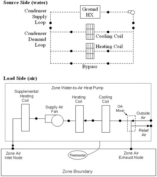
Figure 96. Zone Water to Air Heat Pump Schematic for a DrawThrough Configuration with Ground Heat Exchanger
This alpha field contains the identifying name for the zone system heat pump.
This alpha field contains the schedule name (ref. Schedule) that contains information on the availability of the heat pump to operate. A schedule value greater than 0 (usually 1 is used) indicates that the unit can be on during the hour. A value less than or equal to 0 (usually 0 is used) denotes that the unit must be off for the hour.
This alpha field contains the name of the HVAC system node from which the heat pump draws its inlet air. This node must be a zone exhaust node as specified in a ZoneHVAC:EquipmentConnections object.
This alpha field contains the name of the HVAC system node to which the heat pump sends its outlet air. This node must be a zone inlet node as specified in a ZoneHVAC:EquipmentConnections object.
This field specifies the type of outdoor air mixer used by this WaterToAirHeatPump unit. The outdoor air mixer component is part of the WaterToAirHeatPump compound object. The only available outdoor air mixer type is:
OutdoorAir:Mixer
This alpha field defines the name of an outdoor air mixer component which composes part of the zone WaterToAirHeatPump. The return air stream node of the outdoor air mixer should also be the same node as the air inlet node of the WaterToAirHeatPump. Furthermore, the outdoor air mixer’s mixed air node should be the same as the WaterToAirHeatPump’s fan inlet air node (for blow through fan placement) or the WaterToAirHeatPump’s cooling coil inlet node (for draw through fan placement).
This numeric field defines the supply air flow rate leaving the heat pump in cubic meters per second when the DX cooling coil is operating. Values must be greater than 0 or this field is autosizable.
This numeric field defines the supply air flow rate leaving the heat pump in cubic meters per second when the DX heating coil and/or supplemental heater are operating. Values must be greater than 0 or this field is autosizable.
This numeric field defines the supply air flow rate leaving the heat pump in cubic meters per second when neither cooling or heating is required (i.e., DX coils and supplemental heater are off but the supply air fan operates). This field is only used when the heat pump’s supply air fan operating mode schedule specifies continuous fan operation. Values must be greater than or equal to zero, or this field is autosizable. If the heat pump’s supply air fan operating mode schedule specifies continuous fan operation and this value is set to zero or this field is left blank, then the model assumes that the supply air flow rate when no cooling/heating is needed is equal to the supply air flow rate when the cooling or heating coil was last operating (for cooling operation or heating operation).
This numeric field defines the outdoor air flow rate through the heat pump in cubic meters per second when the DX cooling coil is operating. Values must be greater than or equal to 0, or this field is autosizable. Note that the outside air flow rate during cooling operation is fixed; it cannot change during the simulation. In addition, the outside air flow rate during cooling operation cannot be greater than the heat pump’s supply air volumetric flow rate during cooling operation.
This numeric field defines the outdoor air flow rate through the heat pump in cubic meters per second when the DX heating coil and/or supplemental heater are operating. Values must be greater than or equal to 0, or this field is autosizable. Note that the outside air flow rate during heating operation is fixed; it cannot change during the simulation. In addition, the outside air flow rate during heating operation cannot be greater than the heat pump’s supply air volumetric flow rate during heating operation.
This numeric field defines the outdoor air flow rate through the heat pump in cubic meters per second when neither cooling or heating is required (i.e., DX coils and supplemental heater are off but the supply air fan operates). Values must be greater than or equal to 0, or this field is autosizable. Note that the outside air flow rate when no cooling/heating is needed is fixed; it cannot change during the simulation. In addition, the outside air flow rate when no cooling/heating is needed cannot be greater than the heat pump’s supply air volumetric flow rate when no cooling/heating is needed. This field is only used when the heat pump’s supply air fan operating mode schedule specifies continuous fan operation. If the heat pump’s supply air fan operating mode schedule specifies continuous fan operation and the field ‘Supply air volumetric flow rate when no cooling or heating is needed’ is set to zero or is left blank, then the model assumes that the outside air flow rate when no cooling/heating is needed is equal to the outside air flow rate when the cooling or heating coil was last operating (for cooling operation [i.e., Outside air volumetric flow rate during cooling operation] or heating operation [i.e., Outside air volumetric flow rate during heating operation]) and this field is not used.
This alpha field contains the identifying type of supply air fan specified in the heat pump. Fan type must be Fan:OnOff.
This alpha field contains the identifying name given to the heat pump supply air fan, and should match the name specified in the corresponding fan object.
This alpha field contains the identifying type of heating coil specified in the heat pump. The only valid type is Coil:Heating:WaterToAirHeatPump:EquationFit.
This alpha field contains the identifying name given to the WaterToAirHeatPump heating coil, and should match the name specified in the corresponding WaterToAirHeatPump heating coil object.
This alpha field contains the identifying type of cooling coil specified in the heat pump. The only valid type is Coil:Cooling:WaterToAirHeatPump:EquationFit.
This alpha field contains the identifying name given to the WaterToAirHeatPump cooling coil, and should match the name specified in the corresponding WaterToAirHeatPump cooling coil object.
This numeric field contains the maximum on-off cycling rate for the compressor, which occurs at 50% run time fraction. Suggested values are shown below (Henderson et al. 1999):
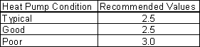
This numeric field contains the time constant for the cooling coil's capacity to reach steady state after startup. Suggested values are shown below (Henderson et al. 1999):
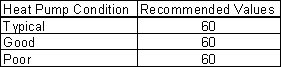
This numeric field contains the fraction of on-cycle power use to adjust the part load fraction based on the off-cycle power consumption due to crankcase heaters, controls, fans, and etc. Suggested value values are below (Henderson et al. 1999):
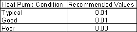
This numeric field contains the time delay in seconds for the heat pump supply air fan to shut off after compressor cycle off. This value can be obtained from the manufacturer or the heat pump catalog. Suggested value is 60 seconds. This value is disregared at times when the WaterToAirHeatPump’s fan operating mode schedule value is greater than 0 (i.e., continuous fan mode).
This is the object type of the supplemental heating coil. The only valid choices are:
Coil:Heating:Electric
Coil:Heating:Gas
This alpha field contains the identifying name given to the supplemental heating coil, and should match the name specified in the corresponding supplemental heating coil object.
This numeric field defines the maximum allowed supply air temperature exiting the heat pump supplemental heating coil in degrees Celsius.
This numeric field defines the outdoor air dry-bulb temperature in degrees Celsius above which the heat pump supplemental heating coil is disabled. The temperature for this input field must be less than or equal to 21 C. If this input field is left blank, the default value is 21 C.
This alpha field specifies the name of the outdoor node which controls the operation of the supplemental heating coil. If this field is left blank, the outdoor temperature is based solely on the weather data. If this field is not blank, the node name specified must also be listed in an OutdoorAir:Node object where the height of the node is taken into consideration when calculating outdoor temperature from the weather data. Alternately, the node name must be specified in an OutdoorAir:NodeList object where the outdoor temperature is taken directly from the weather data.
This alpha field has two choices: BlowThrough or DrawThrough. The first choice represents a blow through system where the supply air fan is before the WaterToAirHeatPump cooling/heating coil and the supplementary heating coil. The second choice represents a draw through system where the supply fan is between the WaterToAirHeatPump cooling/heating coil and the supplementary heating coil. If this input field is left blank, the default is blow through.
This alpha field specifies the name of the supply air fan operating mode schedule. The supply air fan operating mode may vary during the simulation based on time-of-day or with a change of season. Schedule values of 0 denote that the supply air fan and the heating or cooling coil cycle on and off together to meet the heating or cooling load (a.k.a. AUTO fan). Schedule values other than 0 denote that the supply air fan runs continuously while the heating or cooling coil cycles to meet the load. If this field is left blank, the model assumes the supply air fan cycles with the heating or cooling coil throughout the simulation.
As shown in the example below, correct specifications of the WatertoAirHeatPump requires specification of the following objects in addition to the ZoneHVAC:WaterToAirHeatPump object:
n On/Off fan
n WatertoAirHeatPump cooling coil (EquationFit only)
n WatertoAirHeatPump heating coil (EquationFit only)
n Supplementary heating coil
n Outdoor air mixer
n Condenser loop or plant loop demand branches
This optional input field is the name of an AvailabilityManagerAssignmentList object. An Availability Manager Assignment List is a list of Availability Managers giving both Availability Manager type and name. The availability managers in the list apply to this WatertoAirHeatPump or object’s fan. If the WatertoAirHeatPump is available (per the Availability Schedule Name input field above) and this input field has a valid availability manager assignment list name, then the availability managers in the list determine when and if the fan of this WatertoAirHeatPump object should be on or off.
Examples of IDF use:
ZoneHVAC:WaterToAirHeatPump,
Zone1WTAHP, !- Name
FanAndCoilAvailSched, !- Availability Schedule Name
Zone 1 Outlet Node, !- Air Inlet Node Name
Zone 1 Inlet Node, !- Air Outlet Node Name
OutdoorAir:Mixer, !- Outdoor air mixer object type
Zone 1 Mixer, !- Outdoor Air Mixer Name
Autosize, !- Supply Air Flow Rate During Cooling Operation {m3/s}
Autosize, !- Supply Air Flow Rate During Heating Operation {m3/s}
, !- Supply Air Flow Rate When No Cooling or Heating is Needed {m3/s}
0.0, !- Outdoor Air Flow Rate During Cooling Operation {m3/s}
0.0, !- Outdoor Air Flow Rate During Heating Operation {m3/s}
, !- Outdoor Air Flow Rate When No Cooling or Heating is Needed {m3/s}
Fan:OnOff, !- Supply Air Fan Object Type
Zone 1 Fan, !- Supply Air Fan Name
Coil:Heating:WaterToAirHeatPump:EquationFit, !- Heating Coil Object Type
Sys 1 Heat Pump Heating Mode, !- Heating Coil Name
Coil:Cooling:WaterToAirHeatPump:EquationFit, !- Cooling Coil Object Type
Sys 1 Heat Pump Cooling Mode, !- Cooling Coil Name
2.5, !- Maximum Cycling Rate
60.0, !- Heat Pump Time Constant
0.01, !- Fraction of On-Cycle Power Use
60, !- Heat Pump Fan Delay Time
Coil:Heating:Gas, !- Supplemental Heating Coil Object Type
Heat Pump DX Supp Heating Coil 1, !- Supplemental Heating Coil Name
60.0, !- Maximum Supply Air Temperature from Supplemental Heater {C}
20.0, !- Maximum Outdoor Dry-Bulb Temperature for Supplemental Heater Operation {C}
Sys 1 Outside Air Inlet Node, !- Outdoor Dry-Bulb Temperature Sensor Node Name
BlowThrough, !- Fan Placement
CyclingFanSch; !- Supply Air Fan Operating Mode Schedule Name
Schedule:Compact,
CyclingFanSch, !- Name
Fraction, !- Schedule Type Limits Name
Through: 12/31, !- Field 1
For: AllDays, !- Field 2
Until: 24:00, !- Field 3
0.0; !- Field 4
Coil:Heating:WaterToAirHeatPump:EquationFit,
Sys 1 Heat Pump Heating Mode, !- Name
Sys 1 Water to Air Heat Pump Source Side2 Inlet Node, !- Water Inlet Node Name
Sys 1 Water to Air Heat Pump Source Side2 Outlet Node, !- Water Outlet Node Name
Sys 1 Heating Coil Air Inlet Node, !- Air Inlet Node Name
Sys 1 SuppHeating Coil Air Inlet Node, !- Air Outlet Node Name
Autosize, !- Rated Air Flow Rate {m3/s}
Autosize, !- Rated Water Flow Rate {m3/s}
Autosize, !- Rated Heating Capacity {W}
4.75, !- Rated Heating Coefficient of Performance
-1.361311959, !- Heating Capacity Coefficient 1
-2.471798046, !- Heating Capacity Coefficient 2
4.173164514, !- Heating Capacity Coefficient 3
0.640757401, !- Heating Capacity Coefficient 4
0.0, !- Heating Capacity Coefficient 5
-2.176941116, !- Heating Power Consumption Coefficient 1
0.832114286, !- Heating Power Consumption Coefficient 2
1.570743399, !- Heating Power Consumption Coefficient 3
0.690793651, !- Heating Power Consumption Coefficient 4
0.0; !- Heating Power Consumption Coefficient 5
OutdoorAir:Mixer,
Zone 1 Mixer, !- Name
Sys 1 Mixed Air Node, !- Mixed Air Node Name
Sys 1 Outside Air Inlet Node, !- Outdoor Air Stream Node Name
Sys 1 Relief Air Outlet Node, !- Relief Air Stream Node Name
Zone 1 Outlet Node; !- Return Air Stream Node Name
Fan:OnOff,
Zone 1 Fan, !- Name
FanAndCoilAvailSched, !- Availability Schedule Name
0.7, !- Fan Efficiency
300.0, !- Pressure Rise {Pa}
Autosize, !- Maximum Flow Rate {m3/s}
0.9, !- Motor Efficiency
1.0, !- Motor In Airstream Fraction
Sys 1 Mixed Air Node, !- Air Inlet Node Name
Sys 1 Cooling Coil Air Inlet Node; !- Air Outlet Node Name
Coil:Heating:Gas,
Heat Pump DX Supp Heating Coil 1, !- Name
FanAndCoilAvailSched, !- Availability Schedule Name
0.8, !- Gas Burner Efficiency
32000, !- Nominal Capacity {W}
Sys 1 SuppHeating Coil Air Inlet Node, !- Air Inlet Node Name
Zone 1 Inlet Node; !- Air Outlet Node Name
BRANCH,
Gshp Cooling Condenser Branch, !- Name
0, !- Maximum Flow Rate {m3/s}
, !- Pressure Drop Curve Name
Coil:Cooling:WaterToAirHeatPump:ParameterEstimation, !- Component 1 Object Type
Heat Pump Cooling Mode, !- Component 1 Name
Water to Air Heat Pump Source Side1 Inlet Node, !- Component 1 Inlet Node Name
Water to Air Heat Pump Source Side1 Outlet Node, !- Component 1 Outlet Node Name
ACTIVE; !- Component 1 Branch Control Type
BRANCH,
Gshp Heating Condenser Branch, !- Name
0, !- Maximum Flow Rate {m3/s}
, !- Pressure Drop Curve Name
Coil:Heating:WaterToAirHeatPump:ParameterEstimation, !- Component 1 Object Type
Heat Pump Heating Mode, !- Component 1 Name
Water to Air Heat Pump Source Side2 Inlet Node, !- Component 1 Inlet Node Name
Water to Air Heat Pump Source Side2 Outlet Node, !- Component 1 Outlet Node Name
ACTIVE; !- Component 1 Branch Control Type
HVAC,Average,Zone Water Source Heat Pump Total Zone Heating Rate[W]
HVAC,Sum,Zone Water Source Heat Pump Total Zone Heating Energy[J]
HVAC,Average,Zone Water Source Heat Pump Total Zone Cooling Rate[W]
HVAC,Sum,Zone Water Source Heat Pump Total Zone Cooling Energy[J]
HVAC,Average,Zone Water Source Heat Pump Sensible Zone Heating Rate[W]
HVAC,Sum,Zone Water Source Heat Pump Sensible Zone Heating Energy[J]
HVAC,Average,Zone Water Source Heat Pump Sensible Zone Cooling Rate[W]
HVAC,Sum,Zone Water Source Heat Pump Sensible Zone Cooling Energy[J]
HVAC,Average,Zone Water Source Heat Pump Latent Zone Heating Rate[W]
HVAC,Sum,Zone Water Source Heat Pump Latent Zone Heating Energy[J]
HVAC,Average,Zone Water Source Heat Pump Latent Zone Cooling Rate[W]
HVAC,Sum,Zone Water Source Heat Pump Latent Zone Cooling Energy[J]
HVAC,Average,Zone Water Source Heat Pump Electric Power[W]
HVAC,Sum,Zone Water Source Heat Pump Electric Consumption[J]
HVAC,Average,Zone Water Source Heat Pump Fan Part-Load Ratio
HVAC,Average,Zone Water Source Heat Pump Compressor Part-Load Ratio
HVAC,Average,Zone Water Source Heat Pump Fan Availability Status[]
This output field is the total (enthalpy) heat addition rate of the Water to Air Heat Pump to the zone it is serving in Watts. This value is calculated using the enthalpy difference of the heat pump outlet air and inlet air streams, and the air mass flow rate through the heat pump. This value is calculated for each HVAC system time step being simulated, and the results (enthalpy addition only) are averaged for the time step being reported.
This output field is the total (enthalpy) heat addition of the Water to Air Heat Pump to the zone it is serving in Joules over the time step being reported. This value is calculated using the enthalpy difference of the heat pump outlet air and inlet air streams, the air mass flow rate through the heat pump, and the HVAC simulation time step. This value is calculated for each HVAC system time step being simulated, and the results (enthalpy addition only) are summed for the time step being reported.
This output field is the total (enthalpy) heat extraction rate of the Water to Air Heat Pump from the zone it is serving in Watts. This value is calculated using the enthalpy difference of the heat pump outlet air and inlet air streams, and the air mass flow rate through the heat pump. This value is calculated for each HVAC system time step being simulated, and the results (enthalpy extraction only) are averaged for the time step being reported.
This output field is the total (enthalpy) heat extraction of the Water to Air Heat Pump from the zone it is serving in Joules over the time step being reported. This value is calculated using the enthalpy difference of the heat pump outlet air and inlet air streams, the air mass flow rate through the heat pump, and the HVAC simulation time step. This value is calculated for each HVAC system time step being simulated, and the results (enthalpy extraction only) are summed for the time step being reported.
This output field is the sensible heat addition rate of the Water to Air Heat Pump to the zone it is serving in Watts. This value is calculated using the enthalpy difference of the heat pump outlet air and inlet air streams at a constant humidity ratio, and the air mass flow rate through the heat pump. This value is calculated for each HVAC system time step being simulated, and the results (heating only) are averaged for the time step being reported.
This output field is the sensible heat addition of the Water to Air Heat Pump to the zone it is serving in Joules over the time step being reported. This value is calculated using the enthalpy difference of the heat pump outlet air and inlet air streams at a constant humidity ratio, the air mass flow rate through the heat pump, and the HVAC simulation time step. This value is calculated for each HVAC system time step being simulated, and the results (heating only) are summed for the time step being reported.
This output field reports the moist air sensible heat extraction rate of the Water to Air Heat Pump from the zone it is serving in Watts. This value is calculated using the enthalpy difference of the heat pump outlet air and inlet air streams at a constant humidity ratio, and the air mass flow rate through the heat pump. This value is calculated for each HVAC system time step being simulated, and the results (cooling only) are averaged for the time step being reported.
This output field reports the moist air sensible heat extraction of the Water to Air Heat Pump from the zone it is serving in Joules over the time step being reported. This value is calculated using the enthalpy difference of the heat pump outlet air and inlet air streams at a constant humidity ratio, the air mass flow rate through the heat pump, and the HVAC simulation time step. This value is calculated for each HVAC system time step being simulated, and the results (cooling only) are summed for the time step being reported.
This output field is the latent heat addition (humidification) rate of the Water to Air Heat Pump to the zone it is serving in Watts. This value is calculated as the difference between the total energy rate and the sensible energy rate provided by the WaterToAirHP heat pump. This value is calculated for each HVAC system time step being simulated, and the results (latent heat addition only) are averaged for the time step being reported.
This output field is the latent heat addition (humidification) of the Water to Air Heat Pump to the zone it is serving in Joules over the time step being reported. This value is calculated as the difference between the total energy delivered to the zone and the sensible energy delivered to the zone by the WaterToAirHP heat pump. This value is calculated for each HVAC system time step being simulated, and the results (latent heat addition only) are summed for the time step being reported.
This output field is the latent heat extraction (dehumidification) rate of the Water to Air Heat Pump from the zone it is serving in Watts. This value is calculated as the difference between the total energy rate and the sensible energy rate provided by the WaterToAirHP heat pump. This value is calculated for each HVAC system time step being simulated, and the results (latent heat extraction only) are averaged for the time step being reported.
This output field is the latent heat extraction (dehumidification) of the Water to Air Heat Pump from the zone it is serving in Joules over the time step being reported. This value is calculated as the difference between the total energy delivered to the zone and the sensible energy delivered to the zone by the WaterToAirHP heat pump. This value is calculated for each HVAC system time step being simulated, and the results (latent heat extraction only) are summed for the time step being reported.
This output field is the electricity consumption rate of the Water to Air Heat Pump in Watts. The consumption includes electricity used by the compressor (including crankcase heater), fans (indoor supply air fan and the condenser fan), and the supplemental heating coil (if electric). This value is calculated for each HVAC system time step being simulated, and the results are averaged for the time step being reported.
This output field is the electricity consumption of the Water to Air Heat Pump in Joules for the time period being reported. The consumption includes electricity used by the compressor (including crankcase heater), fans (indoor supply air fan and the condenser fan), and the supplemental heating coil (if electric). This value is calculated for each HVAC system time step being simulated, and the results are summed for the time step being reported.
This output field is the part-load ratio of the fan. The fan part-load ratio is defined as the average supply air mass flow rate divided by the maximum supply air mass flow rate. The maximum supply air mass flow rate depends on whether heating, cooling, or no heating or cooling is required during the time step. This value is calculated for each HVAC system time step being simulated, and the results are averaged for the time step being reported.
This output field is the part-load ratio of the compressor used by the DX coils (cooling and heating). Compressor part-load ratio is defined as the total coil load divided by the coil steady-state capacity. This value is calculated for each HVAC system time step being simulated, and the results are averaged for the time step being reported.
This is the availability status of the zone water source heat pump fan. This status flag is a result of the calculations made by the Availability Manager(s) listed in an AvailabilityManagerAssignmentList object. This list is an optional input in the zone water source heat pump object. When a single availability manager is used in an Availability Manager Assignment List, this is also the availability status reported by the specific availability manager (Ref. AvailabilityManager:* Outputs). For multiple availability managers in an Availability Manager Assignment List, rules to determine fan availability status are described in the section ‘Group – System Availability Managers’. The control status outputs are represented using integers 0 through 3. These integers represent NoAction (0), ForceOff (1), CycleOn (2), and CycleOnZoneFansOnly (3). Since the status output is averaged, the output result may not correspond to the values described here when report variable frequencies other than detailed are used. Use the “detailed” reporting frequency (Ref. Report Variable) to view the availability status at each simulation timestep.
This object can be used for modeling conventional mechanical dehumidifiers. These systems use a direct expansion (DX) cooling coil to cool and dehumidify an airstream. Heat from the DX system’s condenser section is rejected into the cool/dehumidified airstream, resulting in warm dry air being supplied from the unit. In EnergyPlus, this object is modeled as a type of zone equipment (ref. ZoneHVAC:EquipmentList and ZoneHVAC:EquipmentConnections).
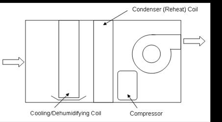
Figure 97. Schematic of a mechanical dehumidifier
The model has inputs for water removal, energy factor and air flow rate at rated conditions (26.7°C, 60% RH). Curve objects must be specified to describe performance at off-rated conditions. A part-load cycling curve input must also be specified to account for inefficiencies due to cycling. Other inputs including minimum and maximum operating temperatures for dehumidifier operation, off-cycle parasitic load, and an input to direct the removed water to a storage tank.
The model assumes that this equipment dehumidifies and heats the air. If used in tandem with another system that cools and dehumidifies the zone air, then the zone dehumidifier should be specified as the lowest cooling priority in the ZoneHVAC:EquipmentList object for best control of zone temperature and humidity levels (e.g., if there are 3 pieces of equipment in ZoneHVAC:EquipmentList, then the zone dehumidifier should have Cooling Priority = 3). With this zone equipment prioritization, the other cooling and dehumidification system would operate first to meet the temperature setpoint (and possibly meet the high humidity setpoint as well). If additional dehumidification is needed, then the zone dehumidifier would operate. The sensible heat generated by the dehumidifier is carried over to the zone air heat balance for the next HVAC time step.
A unique user-assigned name for an instance of a zone DX dehumidifier unit. Any reference to this dehumidifier by another object will use this name.
This alpha field defines the name of the schedule (ref: Schedule) that denotes whether the dehumidifier operates during a given time period. A schedule value equal to 0 denotes that the dehumidifier will not operate for that time period. A value greater than 0 denotes that the dehumidifier is available to operate during that time period.
This alpha field defines the name of the HVAC system node from which the dehumidifier draws its inlet air. This node name must be the name of a zone air exhaust node (ref. ZoneHVAC:EquipmentConnections).
This alpha field defines the name of the HVAC system node to which the dehumidifier sends its outlet air. This node name must be the name of a zone air inlet node (ref. ZoneHVAC:EquipmentConnections).
This numeric input is the full load water removal rate, in liters per day, at rated conditions (air entering the dehumidifier at 26.7°C [80°F] dry-bulb and 60% relative humidity, and air flow rate as defined by field “Rated Air Flow Rate” below). This is a required input field and the entered value must be greater than zero.
This numeric input is the energy factor (liters of water removed per kWh of electricity consumed) at rated conditions (air entering the dehumidifier at 26.7°C [80°F] dry-bulb and 60% relative humidity, and air flow rate as defined by field “Rated Air Flow Rate” below). This is a required input field and the entered value must be greater than zero.
This numeric input is the volumetric air flow rate through the dehumidifier, in m3 per second, at rated conditions (air entering the dehumidifier at 26.7°C [80°F] dry-bulb and 60% relative humidity). This is a required input field and the entered value must be greater than zero.
This alpha field defines the name of a biquadratic performance curve (ref: Performance Curves) that parameterizes the variation of water removal as a function of the dry-bulb temperature (°C) and relative humidity (%) of the air entering the dehumidifier. The output of this curve is multiplied by the Rated Water Removal to give the water removal of the dehumidifier at specific operating conditions (i.e., at temperatures and relative humidity levels different from the rating point conditions). The curve should be normalized to have the value of 1.0 at the rating point (air entering the dehumidifier at 26.7°C [80°F] dry-bulb and 60% relative humidity, and air flow rate as defined by field “Rated Air Flow Rate” above).
This alpha field defines the name of a biquadratic performance curve (ref: Performance Curves) that parameterizes the variation of the energy factor as a function of the dry-bulb temperature (°C) and relative humidity (%) of the air entering the dehumidifier. The output of this curve is multiplied by the Rated Energy Factor to give the energy factor of the dehumidifier at specific operating conditions (i.e., at temperatures and relative humidity levels different from the rating point conditions). The curve should be normalized to have the value of 1.0 at the rating point (air entering the dehumidifier at 26.7°C [80°F] dry-bulb and 60% relative humidity, and air flow rate as defined by field “Rated Air Flow Rate” above).
This alpha field defines the name of a quadratic or cubic performance curve (ref: Performance Curves) that parameterizes the variation of electrical power input to the dehumidifier as a function of the part load ratio (PLR, defined as the water removal load to be met (kg/s) divided by the dehumidifier’s water removal rate (kg/s) at the current operating conditions). The part load fraction (PLF) correlation accounts for efficiency losses due to compressor cycling.
The part load fraction correlation should be normalized to a value of 1.0 when the part load ratio equals 1.0 (i.e., no efficiency losses when the dehumidifier runs continuously for the simulation timestep). For PLR values between 0 and 1 (0 <= PLR < 1), the following rules apply:
0.7 <= PLF <= 1.0 and PLF >= PLR
If PLF < 0.7 a warning message is issued, the program resets the PLF value to 0.7, and the simulation proceeds. The runtime fraction of the dehumidifier is defined as PLR/PLF. If PLF < PLR, then a warning message is issued and the runtime fraction of the dehumidifier is set to 1.0.
Mechanical dehumidifier typically have long runtimes with minimal compressor cycling. So, a typical part load fraction correlation might be:
PLF = 0.95 + 0.05(PLR)
If the user wishes to model no efficiency degradation due to compressor cycling, the part load fraction correlation should be defined as follows:
PLF = 1.0 + 0.0(PLR)
This numeric field defines the minimum inlet air dry-bulb temperature for dehumidifier operation. The dehumidifier will not operate if the inlet air temperature is below this value. This input value must be less than the Maximum Dry-Bulb Temperature for Dehumidifier Operation, and the default value is 10°C.
This numeric field defines the maximum inlet air dry-bulb temperature for dehumidifier operation. The dehumidifier will not operate if the inlet air temperature is above this value. This input value must be greater than the Minimum Dry-Bulb Temperature for Dehumidifier Operation, and the default value is 35°C.
This numeric field contains the off-cycle parasitic electric power in Watts. This is the parasitic electric power consumed by controls or other electrical devices associated with the dehumidifier. This parasitic electric load is consumed whenever the dehumidifier is available to operate, but is not operating. The model assumed that this parasitic power contributes to heating the zone air (i.e., affects the zone air heat balance). The minimum value for this field is 0.0, and the default value is also 0.0 if this field is left blank.
This field is optional. It is used to specify where condensate from the dehumidifier is collected. If blank or omitted, then any water (condensate) removed is discarded. Enter the name of a Water Storage Tank (ref. WaterUse:Storage) object defined elsewhere and the condensate will then be collected in that tank.
Following is an example input for a zone DX dehumidifier object. A ZoneControl:Humidistat object must also be specified for the zone to which the dehumidifier is connected (connect via a zone air exhaust node and a zone air inlet node, ref. ZoneHVAC:EquipmentConnections).
ZoneHVAC:Dehumidifier:DX,
North Zone Dehumidifier, !- Name
ON, !- Availability Schedule Name
Zone3DehumidifierInlet, !- Air Inlet Node Name
Dehumidifier Outlet Node, !- Air Outlet Node Name
50.16, !- Rated Water Removal {L/day} (106 pints/day)
3.412, !- Rated Energy Factor {L/kWh} (7.21 pints/kWh)
0.12036, !- Rated Air Flow Rate {m3/s} (255 cfm)
ZoneDehumidWaterRemoval, !- Water Removal Curve Name
ZoneDehumidEnergyFactor, !- Energy Factor Curve Name
ZoneDehumidPLFFPLR, !- Part Load Fraction Correlation Curve Name
10.0, !- Minimum Dry-Bulb Temperature for Compressor Operation {C}
32.0, !- Maximum Dry-Bulb Temperature for Compressor Operation {C}
0.0; !- Off Cycle Parasitic Electric Load {W}
ZoneControl:Humidistat,
Zone 3 Humidistat, !- Name
NORTH ZONE, !- Zone Name
Seasonal Relative Humidity Sch; !- Relative Humidity Setpoint Schedule Name
HVAC,Average,Zone Dehumidifier Sensible Heating Rate [W]
HVAC,Sum,Zone Dehumidifier Sensible Heating Energy [J]
HVAC,Average,Zone Dehumidifier Water Removal Rate [kg/s]
HVAC,Sum,Zone Dehumidifier Water Removed [kg]
HVAC,Average,Zone Dehumidifier Electric Power [W]
HVAC,Sum,Zone Dehumidifier Electric Consumption [J]
HVAC,Average,Zone Dehumidifier Off-Cycle Parasitic Electric Power [W]
HVAC,Sum,Zone Dehumidifier Off-Cycle Parasitic Electric Consumption [J]
HVAC,Average,Zone Dehumidifier Part-Load Ratio [-]
HVAC,Average,Zone Dehumidifier Runtime Fraction [-]
HVAC,Average,Zone Dehumidifier Outlet Air Temperature [C]
If Condensate Collection Water Storage Tank Name is specified:
HVAC,Average,Zone Dehumidifier Condensate Volumetric Flow Rate [m3/s]
HVAC,Sum,Zone Dehumidifier Condensate Volume [m3]
This output field is the sensible heating rate output of the dehumidifier in Watts. This is determined by the water removal rate, enthalpy of water evaporation, and the zone dehumidifier electric power. To reduce simulation time, this heating is carried over to the zone air heat balance for the next HVAC time step (i.e., it is reported here for the current time step but actually impacts the zone air heat balance on the following HVAC time step). This value is calculated for each HVAC system timestep, and the results are averaged for the timestep being reported.
This output field is the sensible heating output of the dehumidifier in Joules over the timestep being reported. This is determined by the water removal rate, enthalpy of water evaporation, and the zone dehumidifier electric power. To reduce simulation time, this heating is carried over to the zone air heat balance for the next HVAC time step (i.e., it is reported here for the current time step but actually impacts the zone air heat balance on the following HVAC time step). This value is calculated for each HVAC system timestep, and the results are summed for the timestep being reported.
This output field is the water removal rate by the dehumidifier in kg/s. This value is calculated for each HVAC system timestep, and the results are averaged for the timestep being reported.
This output field is the water removed by the dehumidifier in kg. This value is calculated for each HVAC system timestep, and the results are summed for the timestep being reported.
These outputs are the electric power and electric consumption of the dehumidifier for the time period being reported. They include all electricity used by the dehumidifier (including off-cycle electric parasitics). These values are calculated for each HVAC system timestep, and the results are averaged (power) or summed (consumption) for the timestep being reported. The electric consumption output is also added to a report meter with Resource Type = Electricity, End Use Key = Cooling, Group Key = System (ref. Report Meter).
These outputs are the parasitic electric power and electric consumption for controls or other electrical devices associated with the dehumidifier. This parasitic electric load is consumed whenever the dehumidifier is available to operate, but is not operating. The model assumes that this parasitic power contributes to heating the zone air (i.e., affects the zone air heat balance). These outputs values are included in the Zone Dehumidifier Electric Power and Zone Dehumidifier Electric Consumption output variables.
This output field is the part-load ratio for the dehumidifier. Part-load ratio is defined as the water removal load to be met (kg/s) divided by the dehumidifier’s water removal rate (kg/s) at the current operating conditions. This value is calculated for each HVAC system timestep, and the results are averaged for the timestep being reported.
This output field is the runtime fraction for the dehumidifier. This value is calculated for each HVAC system timestep, and the results are averaged for the timestep being reported.
This output field is dry-bulb temperature of the air leaving the dehumidifier in Celsius. This value represents the dry-bulb temperature of the air leaving the dehumidifier when it is operating. For periods when the dehumidifier is not operating, the outlet air temperature is set equal to the inlet air temperature. This value is calculated for each HVAC system timestep, and the results are averaged for the timestep being reported.
These outputs are the rate and volume of water removed as condensate by the dehumidifier. These reports only appear if a water storage tank is named in the input object. The condensate volume output is also added to a report meter with Resource Type = OnSiteWater, End Use Key = Condensate, Group Key = System (ref. Report Meter).
|
|
|
|
An optional controller (see object ZoneHVAC:EnergyRecoveryVentilator:Controller) may be used to simulate economizer (free cooling) operation, modify air flow rates based on high indoor humidity, or simulate a “push-button” type economizer controller.
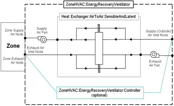
Figure 98. ZoneHVAC:EnergyRecoveryVentilator compound object Schematic
This compound object models the basic operation of supply and exhaust air fans and an air-to-air heat exchanger. The stand alone ERV operates whenever the unit is scheduled to be available (Availability schedule). The stand alone ERV object can be used in conjunction with an economizer feature whereby heat exchange is suspended whenever free cooling is available (i.e., air flow is fully bypassed around a fixed-plate heat exchanger or the rotation of a rotary heat exchanger is stopped). The economizer feature may also be activated based on a time-of-day schedule. Heat exchange is also suspended when air flow rates through the heat exchanger are modified in response to a zone humidistat. When an economizer is used in conjunction with high humidity control, high humidity control has the priority.
To model a stand alone ERV connected to a single zone, the input data file should include the following objects:
· ZoneHVAC:EnergyRecoveryVentilator
· HeatExchanger:AirToAir:SensibleAndLatent
· Fan:OnOff (supply air)
· Fan:OnOff (exhaust air)
· ZoneHVAC:EnergyRecoveryVentilator:Controller (if economizer [free cooling] mode or high humidity control operation is desired)
· ZoneControl:Humidistat (required for high humidity control option)
· SetpointManager:Scheduled (if supply air outlet temperature control is used, Ref. Heat Exchanger:Air to Air:Generic for additional guidance)
· ZoneHVAC:EquipmentConnections
· ZoneHVAC:EquipmentList
· OutdoorAir:NodeList
A description of each input field for this compound object is provided below.
A unique user-assigned name for the stand alone ERV unit. Any reference to this unit by another object will use this name.
The name of the schedule (ref: Schedule) that denotes whether the unit can operate during a given hour. A schedule value greater than 0 (usually 1 is used) indicates that the unit can operate during the hour. A value less than or equal to 0 (usually 0 is used) denotes that the unit will not operate.
The user-assigned name corresponding to the air-to-air heat exchanger used in this compound object. The only allowable type is:.
HeatExchanger:AirToAir:SensibleAndLatent
The supply air flow rate through the ERV unit in cubic meters per second at standard temperature and pressure (dry air at 20o C drybulb). The program uses local barometric pressure to account for altitude using the equation for "standard atmospheric" pressure on p 6.1 of the ASHRAE 1997 HOF (SI edition) to initialize the air systems being simulated.
p=101325*(1-2.25577E-05*Z)**5.2559
where p=pressure in Pa and Z=altitude in m
Note that this flow rate must be within the valid air flow range for the heat exchanger (ref: HeatExchanger:AirToAir:SensibleAndLatent in the Engineering Document). In addition, this flow rate must be less than or equal to the supply fan air flow rate (Fan:OnOff). If the supply air flow rate is less than the exhaust air flow rate, the zone infiltration (ref: ZoneInfiltration) should be specified accordingly (the infiltration induced by imbalanced air flows is not accounted for automatically). The ERV supply air flow rate may also be autosized using the ventilation rate per floor area and/or ventilation rate per occupant fields below. When autosizing, the heat exchanger and fan air flow rates should also be autosized.
Note: The supply air inlet node specified in the generic heat exchanger object must be an outdoor air node (ref: OutdoorAir:Node and OutdoorAir:NodeList). The supply air outlet node specified in the generic heat exchanger object must be a zone air inlet node (ref: ZoneHVAC:EquipmentConnections).
The exhaust air flow rate through the ERV unit in cubic meters per second at standard temperature and pressure (dry air at 20o C drybulb). The program uses local barometric pressure to account for altitude using the equation for "standard atmospheric" pressure on p 6.1 of the ASHRAE 1997 HOF (SI edition) to initialize the air systems being simulated.
p=101325*(1-2.25577E-05*Z)**5.2559
where p=pressure in Pa and Z=altitude in m
Note that this flow rate must be within the valid air flow range for the heat exchanger (ref: HeatExchanger:AirToAir:SensibleAndLatent in the Engineering Document). In addition, this flow rate must be less than or equal to the exhaust fan air flow rate (Fan:OnOff). If the exhaust air flow rate is greater than the supply air flow rate, the zone infiltration (ref: ZoneInfiltration) should be specified accordingly (the infiltration induced by imbalanced air flows is not accounted for automatically). The ERV exhaust air flow rate may also be autosized using the ventilation rate per floor area and/or ventilation rate per occupant fields below. When autosizing, the heat exchanger and fan air flow rates should also be autosized.
Note: The exhaust air inlet node specified in the generic heat exchanger object must be a zone air exhaust node (ref: ZoneHVAC:EquipmentConnections).
The name of the supply air fan used in this object. Fan type must be Fan:OnOff.
The name of the exhaust air fan used in this object. Fan type must be Fan:OnOff.
This optional field specifies the name of the controller used by this compound component if economizer (free cooling) mode or high humidity control operation is desired. Controller type must be ZoneHVAC:EnergyRecoveryVentilator:Controller.
This optional numeric field defines the ventilation rate per unit floor area in cubic meters per second per square meter. This field is only used when the supply and exhaust air flow rates are autosized.
This optional numeric field defines the ventilation rate per occupant in cubic meters per second per occupant. This field is only used when the supply and exhaust air flow rates are autosized.
Following is an example input for this compound object and associated objects that may be defined:
ZoneHVAC:EnergyRecoveryVentilator,
Stand Alone ERV 1, !- Stand alone ERV name
FanAndCoilAvailSched, !- Availability schedule name
OA Heat Recovery 1, !- Heat exchanger name
0.05, !- Supply air flow rate {m3/s}
0.05, !- Exhaust air flow rate {m3/s}
Stand Alone ERV Supply Fan, !- Supply air fan name
Stand Alone ERV Exhaust Fan, !- Exhaust air fan name
ERV OA Controller 1; !- ERV controller name
OutdoorAir:NodeLine,
OutsideAirInletNodes; !- 1st Node name or node list name
NodeList,
OutsideAirInletNodes, !- Node List Name
ERV Outdoor air Inlet Node; !- Node_ID_1
ZoneHVAC:EquipmentConnections,
RESISTIVE ZONE, !- Zone Name
Zone1Equipment, !- List Name: Zone Equipment
Zone1Inlets, !- List Name: Zone Inlet Nodes
Zone1Exhausts, !- List Name: Zone Exhaust Nodes
Zone 1 Node, !- Zone Air Node Name
Zone 1 Outlet Node; !- Zone Return Air Node Name
ZoneHVAC:EquipmentList,
Zone1Equipment, !- Name
ZoneHVAC:EnergyRecoveryVentilator, !- KEY--Zone Equipment Type 1
Stand Alone ERV 1, !- Type Name 1
1, !- Cooling Priority
1; !- Heating Priority
NodeList,
Zone1Inlets, !- Node List Name
Stand Alone ERV Supply Fan Outlet Node; !- Node_ID_1
NodeList,
Zone1Exhausts, !- Node List Name
Zone 1 Exhaust Node; !- Node_ID_1
ZoneHVAC:EnergyRecoveryVentilator:Controller,
ERV OA Controller 1, !- ERV controller name
0.05, !- Outdoor air flow rate {m3/s}
19., !- Temperature high limit {C}
14., !- Temperature low limit {C}
0.0, !- Enthalpy high limit {J/kg}
NoExhaustAirTemperatureLimit, !- Exhaust air temperature limit
NoExhaustAirEnthalpyLimit; !- Exhaust air enthalpy limit
HeatExchanger:AirToAir:SensibleAndLatent,
OA Heat Recovery 1, !- Heat exchanger name
FanAndCoilAvailSched, !- Availability schedule name
0.05, !- Nominal supply air flow rate {m3/s}
.76, !- Sensible effectiveness at 100% airflow heating condition
.68, !- Latent effectiveness at 100% airflow heating condition
.81, !- Sensible effectiveness at 75% airflow heating condition
.73, !- Latent effectiveness at 75% airflow heating condition
.76, !- Sensible effectiveness at 100% airflow cooling condition
.68, !- Latent effectiveness at 100% airflow cooling condition
.81, !- Sensible effectiveness at 75% airflow cooling condition
.73, !- Latent effectiveness at 75% airflow cooling condition
ERV Outdoor air Inlet Node, !- Supply air inlet node name
Heat Recovery Outlet Node, !- Supply air outlet node name
Zone 1 Exhaust Node, !- Exhaust air inlet node name
Heat Recovery Secondary Outlet Node, !- Exhaust air outlet node name
50.0, !- Nominal electric power {W}
Yes, !- Supply air outlet temperature control
Rotary, !- Heat exchanger type
MinimumExhaustTemperature, !- Frost control type
1.7; !- Threshold temperature
Fan:OnOff,
Stand Alone ERV Supply Fan, !- Fan Name
FanAndCoilAvailSched, !- Available Schedule
0.5, !- Fan Total Efficiency
75.0, !- Delta Pressure {Pa}
0.05, !- Max Flow Rate {m3/s}
0.9, !- Motor Efficiency
1.0, !- Motor In Airstream Fraction
Heat Recovery Outlet Node, !- Fan_Inlet_Node
Stand Alone ERV Supply Fan Outlet Node; !- Fan_Outlet_Node
Fan:OnOff,
Stand Alone ERV Exhaust Fan, !- Fan Name
FanAndCoilAvailSched, !- Available Schedule
0.5, !- Fan Total Efficiency
75.0, !- Delta Pressure {Pa}
0.05, !- Max Flow Rate {m3/s}
0.9, !- Motor Efficiency
1.0, !- Motor In Airstream Fraction
Heat Recovery Secondary Outlet Node, !- Fan_Inlet_Node
Stand Alone ERV Exhaust Fan Outlet Node; !- Fan_Outlet_Node
SetpointManager:Scheduled,
Heat Exhchanger Supply Air Temp Manager, !- Name
Temperature, !- Control variable
Heat Exchanger Supply Air Temp Sch, !- Schedule Name
Heat Exchanger Supply Air Nodes; !- Name of the set point Node List
NodeList,
Heat Exchanger Supply Air Nodes, !- Node List Name
Heat Recovery Outlet Node; !- Node_ID_1
HVAC,Average,Stand Alone ERV Electric Power[W]
HVAC,Sum,Stand Alone ERV Electric Consumption[J]
HVAC,Average,Stand Alone ERV Zone Total Cooling Rate[W]
HVAC,Sum,Stand Alone ERV Zone Total Cooling Energy[J]
HVAC,Average,Stand Alone ERV Zone Total Heating Rate[W]
HVAC,Sum,Stand Alone ERV Zone Total Heating Energy[J]
HVAC,Average,Stand Alone ERV Zone Sensible Cooling Rate[W]
HVAC,Sum,Stand Alone ERV Zone Sensible Cooling Energy[J]
HVAC,Average,Stand Alone ERV Zone Sensible Heating Rate[W]
HVAC,Sum,Stand Alone ERV Zone Sensible Heating Energy[J]
HVAC,Average,Stand Alone ERV Zone Latent Cooling Rate[W]
HVAC,Sum,Stand Alone ERV Zone Latent Cooling Energy[J]
HVAC,Average,Stand Alone ERV Zone Latent Heating Rate[W]
HVAC,Sum,Stand Alone ERV Zone Latent Heating Energy[J]
This output field is the electric consumption rate of the stand alone energy recovery ventilator in Watts. This rate includes the electric consumption by the supply air fan, exhaust air fan and the generic air-to-air heat exchanger.
This output field is the electric consumption of the stand alone energy recovery ventilator in Joules for the timestep being reported. This value includes the electric consumption by the supply air fan, exhaust air fan and the generic air-to-air heat exchanger.
This output field is the total (enthalpy) heat extraction rate of the stand alone energy recovery ventilator from the zone in Watts. This value is calculated using the supply air outlet mass flow rate, and the enthalpy difference of the supply outlet and exhaust inlet air streams. This value is calculated for each HVAC system timestep being simulated, and the results (enthalpy extraction only) are averaged for the timestep being reported.
This output field is the total (enthalpy) heat extraction of the stand alone energy recovery ventilator from the zone in Joules over the timestep being reported. This value is calculated using the supply air outlet mass flow rate, the enthalpy difference of the supply outlet and exhaust inlet air streams, and the HVAC system timestep. This value is calculated for each HVAC system timestep being simulated, and the results (enthalpy extraction only) are summed for the timestep being reported.
This output field is the total (enthalpy) heat addition rate of the stand alone energy recovery ventilator to the zone in Watts. This value is calculated using the supply air outlet mass flow rate, and the enthalpy difference of the supply outlet and exhaust inlet air streams. This value is calculated for each HVAC system timestep being simulated, and the results (enthalpy addition only) are averaged for the timestep being reported.
This output field is the total (enthalpy) heat addition of the stand alone energy recovery ventilator to the zone in Joules over the timestep being reported. This value is calculated using the supply air outlet mass flow rate, the enthalpy difference of the supply outlet and exhaust inlet air streams, and the HVAC system timestep. This value is calculated for each HVAC system timestep being simulated, and the results (enthalpy addition only) are summed for the timestep being reported.
This output is the moist air sensible heat extraction rate of the stand alone energy recovery ventilator from the zone in Watts. This value is calculated using the supply air outlet mass flow rate, and the enthalpy difference of the supply outlet and exhaust inlet air streams at a constant humidity ratio. This value is calculated for each HVAC system timestep being simulated, and the results (cooling only) are averaged for the timestep being reported.
This output is the moist air sensible heat extraction of the stand alone energy recovery ventilator from the zone in Joules over the timestep being reported. This value is calculated using the supply air outlet mass flow rate, the enthalpy difference of the supply outlet and exhaust inlet air streams at a constant humidity ratio, and the HVAC system timestep. This value is calculated for each HVAC system timestep being simulated, and the results (cooling only) are summed for the timestep being reported.
This output is the sensible heat addition rate of the stand alone energy recovery ventilator to the zone in Watts. This value is calculated using the supply air outlet mass flow rate, and the enthalpy difference of the supply outlet and exhaust inlet air streams at a constant humidity ratio. This value is calculated for each HVAC system timestep being simulated, and the results (heating only) are averaged for the timestep being reported.
This output is the sensible heat addition of the stand alone energy recovery ventilator to the zone in Joules over the timestep being reported. This value is calculated using the supply air outlet mass flow rate, the enthalpy difference of the supply outlet and exhaust inlet air streams at a constant humidity ratio, and the HVAC system timestep. This value is calculated for each HVAC system timestep being simulated, and the results (heating only) are summed for the timestep being reported.
This output is the latent heat extraction (dehumidification) rate of the stand alone energy recovery ventilator from the zone in Watts. This value is calculated as the difference between the total energy rate and the sensible energy rate provided by the stand alone ERV. This value is calculated for each HVAC system timestep being simulated, and the results (latent heat extraction only) are averaged for the timestep being reported.
This output is the latent heat extraction (dehumidification) of the stand alone energy recovery ventilator from the zone in Joules over the timestep being reported. This value is calculated as the difference between the total energy delivered to the zone and the sensible energy delivered to the zone by the stand alone ERV. This value is calculated for each HVAC system timestep being simulated, and the results (latent heat extraction only) are summed for the timestep being reported.
This output is the latent heat addition (humidification) rate of the stand alone energy recovery ventilator to the zone in Watts. This value is calculated as the difference between the total energy rate and the sensible energy rate provided by the stand alone ERV. This value is calculated for each HVAC system timestep being simulated, and the results (latent heat addition only) are averaged for the timestep being reported.
This output is the latent heat addition (humidification) of the stand alone energy recovery ventilator to the zone in Joules over the timestep being reported. This value is calculated as the difference between the total energy delivered to the zone and the sensible energy delivered to the zone by the stand alone ERV. This value is calculated for each HVAC system timestep being simulated, and the results (latent heat addition only) are summed for the timestep being reported.
Zone terminal units with variable refrigerant flow DX coils are used exclusively with variable refrigerant flow (VRF) air conditioning systems (Ref. AirConditioner:VariableRefrigerantFlow). The zone terminal units are connected to a zone using the inlet and exhaust node names specified in a ZoneHVAC:EquipmentConnections object. The zone exhaust node has the same name as the terminal unit air inlet node. The zone inlet node has the same name as the terminal unit air outlet node. The zone terminal unit is also listed in a zone’s equipment list and will typically be the first equipment operating for both cooling and heating (i.e., Sequence = 1 in the ZoneHVAC:EquipmentList). Other ZoneHVAC equipment may be used in the same zone and should be sequenced to operate after the zone terminal units (i.e., sequence = 2 or higher)
The terminal units operate to satisfy a heating or cooling load in a zone based on a zone thermostat temperature set point. A direct-expansion (DX) cooling and/or DX heating coil is specified depending on the operating mode required. Both a DX cooling and DX heating coil will typically be installed in the terminal unit, however only one may be used if desired. Outdoor ventilation air is modeled with the use of an optional outside air mixer object. Outside air may be provided to the zone only when the coil is operating or can be supplied continuously even when the coil is not operating. A supply air fan is also required and can be modeled as either draw through or blow through.
This alpha field defines a unique user-assigned name for an instance of a variable refrigerant flow zone terminal unit. Any reference to this terminal unit by another object will use this name. The zone terminal unit name must be specified in a ZoneTerminalUnitList object to connect this terminal unit to an AirConditioner:VariableRefrigerantFlow object.
This alpha field defines the name of the schedule (ref: Schedule) that denotes whether the terminal unit operates during a given time period. A schedule value equal to 0 denotes that the terminal unit must be off for that time period. A value greater than 0 denotes that the terminal unit is available to operate during that time period. This schedule may be used to completely disable the terminal unit as required.
This alpha field defines the name of the terminal unit air inlet node. This node name should be the same as a zone exhaust node (ref: ZoneHVAC:EquipmentConnections).
This alpha field defines the name of the terminal unit air outlet node. This node name should be the same as a zone inlet node (ref: ZoneHVAC:EquipmentConnections).
This numeric field defines the terminal unit’s operating volumetric air flow rate in cubic meters per second. This volumetric air flow rate is used when the terminal unit is operating in cooling mode.
This numeric field defines the terminal unit’s operating volumetric air flow rate in cubic meters per second. This volumetric air flow rate is used when the terminal unit’s cooling coil is not operating and the previous mode was cooling.
This numeric field defines the terminal unit’s operating volumetric air flow rate in cubic meters per second. This volumetric air flow rate is used when the terminal unit is operating in heating mode.
This numeric field defines the terminal unit’s operating volumetric air flow rate in cubic meters per second. This volumetric air flow rate is used when the terminal unit’s heating coil is not operating and the previous mode was heating.
This numeric field defines the outdoor air volumetric air flow rate in cubic meters per second. This volumetric air flow rate is used when the terminal unit is operating in cooling mode.
This numeric field defines the outdoor air volumetric air flow rate in cubic meters per second. This volumetric air flow rate is used when the terminal unit is operating in heating mode.
This numeric field defines the outdoor air volumetric air flow rate in cubic meters per second. This volumetric air flow rate is used when the terminal unit is not operating in cooling or heating mode.
This alpha field defines the name of the supply air fan operating mode schedule. Schedule values equal to 0 denote cycling fan/cycling coil operation. All other schedule values denote constant fan/cycling coil operation.
This alpha field has two choices: BlowThrough or DrawThrough. If this field is left blank, the default is blow through.
The first choice stands for “blow through fan”. This means that the unit consists of a fan followed by the DX coils. The fan “blows through” the cooling and heating coils. If an outside air mixer is used, the fan inlet connects to the outside air mixer’s mixed air node. If an outside air mixer is not used, the fan inlet connects to the zone exhaust node. For this configuration, the fan outlet always connects to the DX cooling coil inlet node (or if a DX cooling coil is not used, the DX heating coil inlet node).
The second choice stands for “draw through fan”. This means that the unit consists of the DX coil(s) followed by a fan. The fan “draws air through” the DX coil(s). In this case the fan inlet always connects to the DX heating coil outlet node (or if a DX heating coil is not use, the DX cooling coil outlet node) and the fan outlet node always connects to the zone inlet node.
This choice field contains the identifying type of supply air fan specified for the furnace. Fan type must be Fan:OnOff or Fan:ConstantVolume. Fan:ConstantVolume is used when the Supply Air Fan Operating Mode Schedule values are never 0 and the fan operates continuously. Fan:OnOff is used when the fan cycles on and off with the cooling or heating coil (i.e. Supply Air Fan Operating Mode Schedule values are at times 0).
This alpha field defines the name of the terminal unit’s supply air fan.
This alpha field contains the identifying type of outside air mixer specified for the terminal unit. Outside air mixer type must be OutsideAir:Mixer. This field should be left blank when an outside air mixer is not simulated.
This alpha field defines the name of the terminal unit’s outside air mixer. If this field is left blank, an outside air mixer is not simulated.
This choice field contains the identifying type of the terminal unit’s DX cooling coil. The only valid DX cooling coil type is Coil:Cooling:DX:VariableRefrigerantFlow. This field should be left blank when a DX cooling coil is not simulated.
This alpha field defines the name of the terminal unit’s DX cooling coil. If this field is left blank, a DX cooling coil is not simulated.
This choice field contains the identifying type of the terminal unit’s DX heating coil. The only valid DX heating coil type is Coil:Heating:DX:VariableRefrigerantFlow. This field should be left blank when a DX heating coil is not simulated.
This alpha field defines the name of the terminal unit’s DX heating coil. This field should be left blank when a DX heating coil is not simulated.
This numeric field defines the parasitic electrical energy use of the zone terminal unit when either terminal unit coil is operating. When in cooling mode, this electric energy use is reported in a zone terminal unit cooling electric consumption report variable. When in heating mode, this electric energy use is reported in a zone terminal unit heating electric consumption report variable.
This numeric field defines the parasitic electrical energy use of the zone terminal unit when the terminal unit coil(s) is not operating. When the previous mode was cooling, this electric energy use is reported in a zone terminal unit cooling electric consumption report variable. When the previous mode was heating, this electric energy use is reported in a zone terminal unit heating electric consumption report variable.
Following is an example input for a ZoneHVAC:TerminalUnit:VariableRefrigerantFlow object.
ZoneHVAC :TerminalUnitVariableRefrigerantFlow,
Zone 1 TU, !- Zone Terminal Unit Name
TU Availability Schedule,!- Terminal Unit Availability schedule
TU1 Inlet Node, !- Terminal Unit air inlet node name
TU1 Inlet Node, !- Terminal Unit air outlet node name
0.005, !- Supply Air Flow Rate in Cooling Mode {m3/s}
0, !- Supply Air Flow Rate when Cooling Coil is not active {m3/s}
0.005, !- Supply Air Flow Rate in Heating Mode {m3/s}
0, !- Supply Air Flow Rate when Heating Coil is not active {m3/s}
0.001, !- Outside Air Flow Rate in Cooling Mode
0.001, !- Outside Air Flow Rate in Heating Mode
0, !- Outside Air Flow Rate when no cooling or heating is required
TU1 Fan Op Schedule, !- Supply Air Fan Operating Mode Schedule Name
TU1 SA Fan, !- Supply Air Fan Name
draw through, !- Fan placement
TU! OA Mixer, !- Outside Air Mixer Name
TU1 VRF DX Cooling Coil, !- Cooling Coil Name
TU1 VRF DX Heating Coil, !- Heating Coil Name
33; !- Zone Terminal Unit Parasitic Electric Energy Use {W}
HVAC,Average,Zone Terminal Unit Total Cooling Rate[W]
HVAC,Sum, Zone Terminal Unit Total Cooling Energy[J]
HVAC,Average, Zone Terminal Unit Sensible Cooling Rate[W]
HVAC,Sum, Zone Terminal Unit Sensible Cooling Energy[J]
HVAC,Average, Zone Terminal Unit Latent Cooling Rate[W]
HVAC,Sum, Zone Terminal Unit Latent Cooling Energy[J]
HVAC,Average,Zone Terminal Unit Total Heating Rate[W]
HVAC,Sum, Zone Terminal Unit Total Heating Energy[J]
HVAC,Average, Zone Terminal Unit Sensible Heating Rate[W]
HVAC,Sum, Zone Terminal Unit Sensible Heating Energy[J]
HVAC,Average, Zone Terminal Unit Latent Heating Rate[W]
HVAC,Sum, Zone Terminal Unit Latent Heating Energy[J]
HVAC,Average,Zone Terminal Unit Electric Consumption Rate[W]
HVAC,Sum, Zone Terminal Unit Electric Consumption[J]
This field is the total (sensible and latent) cooling rate output of the terminal unit in Watts. This is determined by terminal unit inlet and outlet air conditions and the air mass flow rate through the unit. This value describes the total energy rate delivered to the zone.
This is the total (sensible plus latent) cooling output of the terminal unit in Joules over the time step being reported. This is determined by the terminal unit inlet and outlet air conditions and the air mass flow rate through the unit. This value describes the total cooling energy delivered to the zone.
This output is the moist air sensible cooling rate output of the terminal unit in Watts. This is determined by enthalpy difference between the inlet and outlet air temperature at a constant humidity ratio, using the minimum of the inlet and outlet air node humidity ratios, and the air mass flow rate through the unit. This value describes the sensible cooling energy rate delivered to the zone.
This is the moist air sensible cooling output of the terminal unit in Joules for the time step being reported. This is determined by enthalpy difference between the inlet and outlet air temperature at a constant humidity ratio, using the minimum of the inlet and outlet air node humidity ratios, and the air mass flow rate through the unit. This value describes the sensible cooling energy delivered to the zone.
This is the latent cooling rate output of the terminal unit in Watts. This is determined by the inlet and outlet air humidity ratios and the air mass flow rate through the unit. This value describes the latent cooling energy rate delivered to the zone.
This is the latent cooling output of the terminal unit in Joules for the time step being reported. This is determined by the inlet and outlet air humidity ratios and the air mass flow rate through the unit. This value describes the latent cooling energy delivered to the zone.
This field is the total enthalpic heating rate output of the terminal unit in Watts. This is determined by the terminal unit inlet and outlet air conditions and the air mass flow rate through the unit. This value describes the total heating energy rate delivered to the zone.
This is the total enthalpic heating output of the terminal unit in Joules over the time step being reported. This is determined by the terminal unit inlet and outlet air conditions and the air mass flow rate through the unit. This value describes the total heating energy delivered to the zone.
This output is the moist air sensible heating rate output of the terminal unit in Watts. This is determined by enthalpy difference between the inlet and outlet air temperature at a constant humidity ratio, using the minimum of the inlet and outlet air node humidity ratios, and the air mass flow rate through the unit. This value describes the sensible heating energy rate delivered to the zone.
This is the moist air sensible heating output of the terminal unit in Joules for the time step being reported. This is determined by enthalpy difference between the inlet and outlet air temperature at a constant humidity ratio, using the minimum of the inlet and outlet air node humidity ratios, and the air mass flow rate through the unit. This value describes the sensible heating energy delivered to the zone.
This is the latent heating rate output of the terminal unit in Watts. This is determined by the inlet and outlet air specific humidity ratios and the air mass flow rate through the unit. This value describes the latent heating energy rate delivered to the zone.
This is the latent heating output of the terminal unit in Joules for the time step being reported. This is determined by the inlet and outlet air specific humidity ratios and the air mass flow rate through the unit. This value describes the latent heating energy delivered to the zone.
This output field is the parasitic electricity consumption rate of the zone terminal unit in Watts. The consumption rate includes parasitic electricity used by the zone terminal unit’s transformers, controls, or other electricity consuming devices. This value is calculated for each HVAC system time step being simulated, and the results are averaged for the time step being reported. The terminal unit parasitic on and off electricity is reported in this cooling report variable when the unit operates in cooling mode or the most recent operation was for cooling.
This output field is the electricity consumption of the zone terminal unit in Joules for the time period being reported. The consumption includes parasitic electricity used by the zone terminal unit’s transformers, controls, or other electricity consuming devices. This value is calculated for each HVAC system time step being simulated, and the results are summed for the time step being reported. The terminal unit parasitic on and off electricity consumption is reported in this cooling report variable when the unit operates in cooling mode or the most recent operation was for cooling. This output is also added to a report meter with Resource Type = Electricity, End Use Key = Cooling, Group Key = System (ref. Report Meter).
This output field is the parasitic electricity consumption rate of the zone terminal unit in Watts. The consumption rate includes parasitic electricity used by the zone terminal unit’s transformers, controls, or other electricity consuming devices. This value is calculated for each HVAC system time step being simulated, and the results are averaged for the time step being reported. The terminal unit parasitic on and off electricity is reported in this heating report variable when the unit operates in heating mode or the most recent operation was for heating.
This output field is the electricity consumption of the zone terminal unit in Joules for the time period being reported. The consumption includes parasitic electricity used by the zone terminal unit’s transformers, controls, or other electricity consuming devices. This value is calculated for each HVAC system time step being simulated, and the results are summed for the time step being reported. The terminal unit parasitic on and off electricity consumption is reported in this heating report variable when the unit operates in heating mode or the most recent operation was for heating. This output is also added to a report meter with Resource Type = Electricity, End Use Key = Heating, Group Key = System (ref. Report Meter).
The components
AirLoopHVAC:Unitary:Furnace:HeatOnly
AirLoopHVAC:Unitary:Furnace:HeatCool
AirLoopHVAC:UnitaryHeatOnly
AirLoopHVAC:UnitaryHeatCool
AirLoopHVAC:UnitaryHeatPump:AirToAir
AirLoopHVAC:UnitaryHeatPump:AirToAir:MultiSpeed
are compound components usually placed in the primary air loop as the sole component. On the zone equipment side they are usually connected to one or more zones through uncontrolled terminal units (i.e., AirTerminal:SingleDuct:Uncontrolled objects). The maximum or design air flow rate through the furnace or unitary system should usually be set equal to the sum of the maximum air flow rates through the terminal unit objects. However, the simulation program can usually account for unequal air flows if the user wishes to model this scenario.
The heat/cool furnace is a “virtual” component that consists of a fan component (OnOff or ConstantVolume), a DX cooling coil component, and a Gas or Electric heating coil component. The blow through furnace configuration is shown in Figure 99 below. When a draw through furnace configuration is desired, the fan is placed directly after the heating coil. If the dehumidification control type is specified as CoolReheat, a reheat coil component is also required. If the reheat coil is present and the dehumidificaiton control type input is not specified as CoolReheat, the reheat coil will not be active,
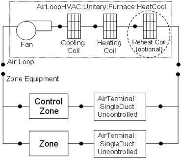
Figure 99. Schematic of EnergyPlus Heat/Cool Furnace
Note: the coil order shown here has been revised from previous versions (prior to V4.0) of Energyplus to configure the cooling coil upstream of the heating coil. This configuration provides uniformity with all unitary equipment. However, for unitary HeatCool systems that do not use a reheat coil, the heating coil can also be placed upstream of the cooling coil. This optional coil placement is retained to allow compatibility with previous versions of Energyplus. For input files developed using previous versions of Energyplus, it is recommended that the coil order be revised according to the figure above.
Links to the fan, heating coil, DX cooling coil and optional reheat coil specifications are provided in the furnace input data syntax. In addition, the control zone name and the furnace design operating conditions are specified by the furnace inputs.
This alpha field contains the identifying name for the unit.
This alpha field contains the schedule name which contains information on the availability of the furnace to operate.
This alpha field contains the furnace inlet node name.
This alpha field contains the furnace outlet node name.
Field: Supply Air Fan Operating Mode Schedule Name
This alpha field specifies the name of the supply air fan operating mode schedule. The supply air fan operating mode may vary during the simulation based on time-of-day or with a change of season. Schedule values of 0 denote that the furnace supply air fan and the heating or cooling coil cycle on and off together to meet the heating or cooling load (a.k.a. AUTO fan). Schedule values other than 0 denote that the supply fan runs continuously while the heating or cooling coil cycles to meet the load.
This numeric field contains the design operating furnace air outlet temperature in degrees C when the furnace is heating. If this input field is left blank, the default value is 80 C.
This numeric field defines the supply air flow rate leaving the furnace in cubic meters per second when the DX cooling coil is operating. Values must be greater than 0 or this field is autosizable.
This numeric field defines the supply air flow rate leaving the furnace in cubic meters per second when the DX heating coil and/or supplemental heater are operating. Values must be greater than 0 or this field is autosizable.
This numeric field defines the supply air flow rate leaving the furnace in cubic meters per second when neither cooling or heating is required (i.e., DX coils and supplemental heater are off but the supply air fan operates). This field is only used when the furnace operating mode is specified as continuous fan operation. Values must be greater than or equal to zero, or this field is autosizable. If the furnace operating mode is specified as continuous fan operation and this value is set to zero or this field is left blank, then the model assumes that the supply air flow rate when no cooling/heating is needed is equal to the supply air flow rate when the compressor was last operating (for cooling operation or heating operation).
This alpha field contains the identifying zone name where the thermostat controlling the furnace is located.
This alpha field contains the identifying type of supply air fan specified for the furnace. Fan type must be Fan:OnOff or Fan:ConstantVolume. Fan:ConstantVolume is used when the Supply Air Fan Operating Mode Schedule values are never 0 and the fan operates continuously. Fan:OnOff is used when the fan cycles on and off with the cooling or heating coil (i.e. Supply Air Fan Operating Mode Schedule values are at times 0).
This alpha field contains the identifying name given to the furnace fan.
This alpha field has two choices: BlowThrough or DrawThrough. The first choice stands for “blow through fan”. This means that the unit consists of a fan followed by the DX coils and supplemental heating coil. The fan “blows through” the cooling and heating coils. The second choice stands for “draw through fan”. This means that the unit consists of the DX coil(s) followed by a fan, with the supplemental heater located at the outlet of the fan. The fan “draws air through” the DX coil(s). If this field is left blank, the default is blow through.
This alpha field contains the identifying type of heating coil specified in the furnace. Only allowable coil types are:
Coil:Heating:Electric
Coil:Heating:Gas
This alpha field contains the identifying name given to the furnace heating coil.
This alpha field contains the identifying type of cooling coil specified in the furnace. Only allowable coil types are:
Coil:Cooling:DX:SingleSpeed
CoilSystem:Cooling:DX:HeatExchangerAssisted
This alpha field contains the identifying name given to the furnace cooling coil.
This alpha field contains the type of dehumidification control. The following options are valid for this field:
None - meet sensible load only, no active dehumidification control
Multimode - activate enhanced dehumidification mode as needed and meet sensible load. This option is used to model DX equipment with a controllable heat exchanger assisting the DX cooling coil for improved dehumidification. It is valid only with cooling coil type = CoilSystem:Cooling:DX:HeatExchangerAssisted.
CoolReheat - cool beyond the dry-bulb temperature set point as required to meet the high humidity setpoint. If cooling coil type = CoilSystem:Cooling:DX:HeatExchangerAssisted, then the heat exchanger is assumed to always transfer energy between the cooling coil’s inlet and outlet airstreams when the cooling coil is operating.
The default is None. For the other dehumidification control modes, the maximum humidity setpoint is used. This must be set using a ZoneControl:Humidistat object. When extra dehumidification is required, the system may not be able to meet the humidity setpoint if its full capacity is not adequate. If the dehumidification control type is specified as CoolReheat, then two additional inputs (reheat coil type and name) are also required as shown below. Although the reheat coil is required only when CoolRheat is selected, the optional reheat coil may be present for any of the allowed Dehumidification Control Types. If the reheat coil is present and the dehumidificaiton control type is not specified as CoolReheat, the reheat coil will not be active,
This alpha field contains the identifying type of reheat coil specified in the furnace. Reheat coil type must be one of:
Coil:Heating:Electric
Coil:Heating:Gas
Coil:Heating:Desuperheater
This alpha field contains the identifying name given to the furnace reheat coil.
As shown in the example below, correct specification of the heat/cool furnace requires specification of the following objects in addition to the furnace object:
1) fan (Fan:OnOff or Fan:ConstantVolume)
2) cooling coil (Coil:Cooling:DX:SingleSpeed or CoilSystem:Cooling:DX:HeatExchangerAssisted)
3) heating coil (Coil:Heating:Gas or Coil:Heating:Electric)
4) reheat coil (optional, Coil:Heating:Gas, Coil:Heating:Electric, or Coil:Heating:Desuperheater)
5) terminal unit (AirTerminal:SingleDuct:Uncontrolled) for each zone served by the furnace
Note: the furnace’s fan, cooling coil, heating coil and optional reheat coil must be connected in the air loop according to the configuration shown above (Figure 99) when CoolReheat is selected as the dehujmidificaiton control type. In addition, the volumetric air flow rate specified in the terminal air unit for the controlling zone should properly reflect the fractional volumetric air flow rate specified in the furnace object.
AirLoopHVAC:Unitary:Furnace:HeatCool,
GasHeat DXAC Furnace 1, !- Name of furnace
FanAndCoilAvailSched, !- Availability schedule
Air Loop Inlet Node, !- Furnace inlet node name
Air Loop Outlet Node, !- Furnace outlet node name
CycFanSchedule, !- Supply Air Fan Operating Mode Schedule Name
80, !- Maximum supply air temperature from furnace heater {C}
1.3, !- Supply air volumetric flow rate during cooling operation {m3/s}
1.3, !- Supply air volumetric flow rate during heating operation {m3/s}
0.0, !- Design air volumetric flow rate when no heating or cooling is needed {m3/s}
East Zone, !- Controlling zone or thermostat location
Fan:OnOff, !- Supply fan type
Supply Fan 1, !- Supply fan name
BlowThrough, !- Fan Placement
Coil:Heating:Gas, !- Heating coil type
Furnace Heating Coil 1, !- Heating coil name
Coil:Cooling:DX:SingleSpeed, !- Cooling coil type
Furnace ACDXCoil 1, !- Cooling coil name
None; !- Dehumidificatioin Control Type
Coil:Heating:Gas,
Furnace Heating Coil 1, !- Coil Name
FanAndCoilAvailSched, !- Available Schedule
0.8, !- Gas Burner Efficiency of the Coil
25000, !- Nominal Capacity of the Coil {W}
Heating Coil Air Inlet Node, !- Coil_Air_Inlet_Node
Air Loop Outlet Node; !- Coil_Air_Outlet_Node
Coil:Cooling:DX:SingleSpeed,
Furnace ACDXCoil 1, !- Coil Name
FanAndCoilAvailSched, !- Availability Schedule
25000, !- Rated Total Cooling Capacity (gross) {W}
0.75, !- Rated SHR
3.0, !- Rated COP
1.3, !- Rated Air Volume Flow Rate {m3/s}
DX Cooling Coil Air Inlet Node, !- Coil Air Inlet Node
Heating Coil Air Inlet Node, !- Coil Air Outlet Node
WindACCoolCapFT, !- Total Cooling Capacity Modifier Curve (function of temperature)
WindACCoolCapFFF, !- Total Cooling Capacity Modifier Curve (function of flow fraction)
WindACEIRFT, !- Energy Input Ratio Modifier Curve (function of temperature)
WindACEIRFFF, !- Energy Input Ratio Modifier Curve (function of flow fraction)
WindACPLFFPLR, !- Part Load Fraction Correlation (function of part load ratio)
CyclingFanAndCompressor; !- Supply Air Fan Operation Mode
Fan:OnOff,
Supply Fan 1, !- Fan Name
FanAndCoilAvailSched, !- Available Schedule
0.7, !- Fan Total Efficiency
600.0, !- Delta Pressure {Pa}
1.3, !- Max Flow Rate {m3/s}
0.9, !- Motor Efficiency
1.0, !- Motor In Airstream Fraction
Air Loop Inlet Node, !- Fan_Inlet_Node
DX Cooling Coil Air Inlet Node; !- Fan_Outlet_Node
AirTerminal:SingleDuct:Uncontrolled,
Zone1DirectAir, !- Direct Air Name
FanAndCoilAvailSched, !- Schedule name for on/off schedule
Zone 1 Inlet Node, !- Zone Supply Air Node Name
0.47; !- Maximum air flow rate {m3/s}
AirTerminal:SingleDuct:Uncontrolled,
Zone2DirectAir, !- Direct Air Name
FanAndCoilAvailSched, !- Schedule name for on/off schedule
Zone 2 Inlet Node, !- Zone Supply Air Node Name
0.36; !- Maximum air flow rate {m3/s}
AirTerminal:SingleDuct:Uncontrolled,
Zone3DirectAir, !- Direct Air Name
FanAndCoilAvailSched, !- Schedule name for on/off schedule
Zone 3 Inlet Node, !- Zone Supply Air Node Name
0.47; !- Maximum air flow rate {m3/s}
Example of Heat/Cool Furnace Specification
HVAC,Average,Furnace Fan Part-Load Ratio
HVAC,Average,Furnace Compressor Part-Load Ratio
This output variable is the ratio of actual air mass flow rate through the furnace to the furnace’s design air mass flow rate (i.e., design volumetric flow rate converted to dry air mass flow rate). For continuous fan operation mode, this variable is always 1.0 when the furnace is available (based on the availability schedule). For cycling fan/cycling coil operation mode, the actual air mass flow rate is calculated based on the ratio of the sensible heating (or cooling) load to the steady-state furnace heating (or cooling) capacity. For the cycling fan mode, the runtime fraction for the furnace fan may be different from the fan part-load ratio reported here due the part-load performance of the furnace’s heating (or cooling) coil (delay at start-up to reach steady-state output). In general, runtime fractions are reported by individual components where appropriate (e.g., Fan:OnOff).
This output variable is the ratio of the sensible cooling load to the steady-state cooling capacity of the furnace’s DX cooling coil. The runtime fraction for the DX cooling coil compressor may be different from the compressor part-load ratio reported here due the part-load performance of the cooling coil (delay at start-up to reach steady-state output). In general, runtime fractions are reported by individual components where appropriate.
The AirLoopHVAC:UnitaryHeatCool object is the identical model to the AirLoopHAVC:Unitary:Furnace:HeatCool object. The heat/cool unitary system is a “virtual” component that consists of a fan component (OnOff or ConstantVolume), a DX cooling coil component and a Gas or Electric heating coil component as shown in Figure 100. When a draw through configuration is desired, the fan is placed directly after the heating coil. If dehumidification control is selected, a reheat coil component is also required. If the reheat coil is present and the dehumidificaiton control type input is not specified as CoolReheat, the reheat coil will not be active,
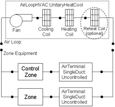
Figure 100. Schematic of Blow Through Heat/Cool Unitary System
Note: the coil order shown here has been revised from previous versions (prior to V4.0) of Energyplus to configure the cooling coil upstream of the heating coil. This configuration provides uniformity with all unitary equipment. However, for unitary HeatCool systems that do not use a reheat coil, the heating coil can also be placed upstream of the cooling coil. This optional coil placement is retained to allow compatibility with previous versions of Energyplus. For input files developed using previous versions of Energyplus, it is recommended that the coil order be revised according to the figure above.
Links to the fan, DX cooling coil, heating coil and optional reheat coil specifications are provided in the unitary system input data syntax. In addition, the control zone name and the system design operating conditions are specified by the unitary system inputs.
This alpha field contains the identifying name for the unitary system.
This alpha field contains the schedule name which contains information on the availability of the unitary system to operate.
This alpha field contains the unitary system inlet node name.
This alpha field contains the unitary system outlet node name.
Field: Supply Air Fan Operating Mode Schedule Name
This alpha field specifies the name of the supply air fan operating mode schedule. The supply air fan operating mode may vary during the simulation based on time-of-day or with a change of season. Schedule values of 0 denote that the unitary system supply air fan and the heating or cooling coil cycle on and off together to meet the heating or cooling load (a.k.a. AUTO fan). Schedule values other than 0 denote that the supply fan runs continuously while the heating or cooling coil cycles to meet the load.
This numeric field contains the design operating air outlet temperature in degrees C when the unitary system is heating. If this input field is left blank, the default value is 80 C.
This numeric field defines the supply air flow rate leaving the unitary system in cubic meters per second when the DX cooling coil is operating. Values must be greater than 0 or this field is autosizable.
This numeric field defines the supply air flow rate leaving the unitary system in cubic meters per second when the DX heating coil and/or supplemental heater are operating. Values must be greater than 0 or this field is autosizable.
This numeric field defines the supply air flow rate leaving the unitary system in cubic meters per second when neither cooling or heating is required (i.e., DX coils and supplemental heater are off but the supply air fan operates). This field is only used when the unitary system operating mode is specified as continuous fan operation. Values must be greater than or equal to zero, or this field is autosizable. If the unitary system operating mode is specified as continuous fan operation and this value is set to zero or this field is left blank, then the model assumes that the supply air flow rate when no cooling/heating is needed is equal to the supply air flow rate when the compressor was last operating (for cooling operation or heating operation).
This alpha field contains the identifying zone name where the thermostat controlling the unitary system is located.
This alpha field contains the identifying type of supply air fan specified for the unitary system. Fan type must be Fan:OnOff or Fan:ConstantVolume. Fan:ConstantVolume is used when the Supply Air Fan Operating Mode Schedule values are never 0 and the fan operates continuously. Fan:OnOff is used when the fan cycles on and off with the cooling or heating coil (i.e. Supply Air Fan Operating Mode Schedule values are at times 0).
This alpha field contains the identifying name given to the unitary system fan.
This alpha field has two choices: BlowThrough or DrawThrough. The first choice stands for “blow through fan”. This means that the unit consists of a fan followed by the DX coils and supplemental heating coil. The fan “blows through” the cooling and heating coils. The second choice stands for “draw through fan”. This means that the unit consists of the DX coil(s) followed by a fan, with the supplemental heater located at the outlet of the fan. The fan “draws air through” the DX coil(s). If this field is left blank, the default is blow through.
This alpha field contains the identifying type of heating coil specified in the unitary system. Only allowable coil types are:
Coil:Heating:Electric
Coil:Heating:Gas
This alpha field contains the identifying name given to the unitary system heating coil.
This alpha field contains the identifying type of cooling coil specified in the unitary system. Only allowable coil types are:
Coil:Cooling:DX:SingleSpeed
CoilSystem:Cooling:DX:HeatExchangerAssisted
This alpha field contains the identifying name given to the unitary system cooling coil.
This alpha field contains the type of dehumidification control. The following options are valid for this field:
None - meet sensible load only, no active dehumidification control
Multimode - activate enhanced dehumidification mode as needed and meet sensible load. This option is used to model DX equipment with a controllable heat exchanger assisting the DX cooling coil for improved dehumidification. It is valid only with cooling coil type = CoilSystem:Cooling:DX:HeatExchangerAssisted.
CoolReheat - cool beyond the dry-bulb temperature set point as required to meet the high humidity setpoint. If cooling coil type = CoilSystem:Cooling:DX:HeatExchangerAssisted, then the heat exchanger is assumed to always transfer energy between the cooling coil’s inlet and outlet airstreams when the cooling coil is operating.
The default is None. For the other dehumidification control modes, the maximum humidity setpoint is used. This must be set using a ZoneControl:Humidistat object. When extra dehumidification is required, the system may not be able to meet the humidity setpoint if its full capacity is not adequate. If the dehumidification control type is specified as CoolReheat, then two additional inputs (reheat coil type and name) are also required as shown below. Although the reheat coil is required only when CoolReheat is selected, the optional reheat coil may be present for any of the allowed Dehumidification Control Types. If the reheat coil is present and the dehumidificaiton control type is not specified as CoolReheat, the reheat coil will not be active,
This alpha field contains the identifying type of reheat coil specified in the furnace. Reheat coil type must be one of:
Coil:Heating:Electric
Coil:Heating:Gas
Coil:Heating:Desuperheater
This alpha field contains the identifying name given to the unitary system reheat coil.
As shown in the example below, correct specification of the heat/cool unitary system requires specification of the following objects in addition to the unitary system object:
1) Fan (Fan:OnOff or Fan:ConstantVolume)
2) Cooling coil (Coil:Cooling:DX:SingleSpeed or CoilSystem:Cooling:DX:HeatExchangerAssisted)
3) Heating coil (Coil:Heating:Gas or Coil:Heating:Electric)
4) Reheat coil (optional, Coil:Heating:Gas, Coil:Heating:Electric, or Coil:Heating:Desuperheater)
5) Direct air unit (AirTerminal:SingleDuct:Uncontrolled) for each zone served by the unitary system
Note: the unitary system’s fan, cooling coil, heating coil and optional reheat coil must be connected in the air loop according to the configuration shown above (Figure 100). In addition, the volumetric air flow rate specified in the direct air unit for the controlling zone should properly reflect the fractional volumetric air flow rate specified in the unitary system object.
AirLoopHVAC:Unitary:Furnace:HeatCool,
GasHeat DXAC Unitary System 1, !- Name of unitary system
FanAndCoilAvailSched, !- Availability schedule
Air Loop Inlet Node, !- Unitary system inlet node name
Air Loop Outlet Node, !- Unitary system outlet node name
CycFanSchedule, !- Supply Air Fan Operating Mode Schedule Name
80, !- Maximum supply air temperature from unitary system heater {C}
1.3, !- Supply air volumetric flow rate during cooling operation {m3/s}
1.3, !- Supply air volumetric flow rate during heating operation {m3/s}
0.0, !- Design air volumetric flow rate when no heating or cooling is needed {m3/s}
East Zone, !- Controlling zone or thermostat location
Fan:OnOff, !- Supply fan type
Supply Fan 1, !- Supply fan name
BlowThrough, !- Fan Placement
Coil:Heating:Gas, !- Heating coil type
Unitary System Heating Coil 1, !- Heating coil name
Coil:Cooling:DX:SingleSpeed, !- Cooling coil type
Unitary System ACDXCoil 1, !- Cooling coil name
None; !- High humidity control
Coil:Heating:Gas,
Unitary System Heating Coil 1, !- Coil Name
FanAndCoilAvailSched, !- Available Schedule
0.8, !- Gas Burner Efficiency of the Coil
25000, !- Nominal Capacity of the Coil {W}
Heating Coil Air Inlet Node, !- Coil_Air_Inlet_Node
Air Loop Outlet Node; !- Coil_Air_Outlet_Node
Coil:Cooling:DX:SingleSpeed,
Unitary System ACDXCoil 1, !- Coil Name
FanAndCoilAvailSched, !- Availability Schedule
25000, !- Rated Total Cooling Capacity (gross) {W}
0.75, !- Rated SHR
3.0, !- Rated COP
1.3, !- Rated Air Volume Flow Rate {m3/s}
DX Cooling Coil Air Inlet Node, !- Coil Air Inlet Node
Heating Coil Air Inlet Node, !- Coil Air Outlet Node
WindACCoolCapFT, !- Total Cooling Capacity Modifier Curve (function of temperature)
WindACCoolCapFFF, !- Total Cooling Capacity Modifier Curve (function of flow fraction)
WindACEIRFT, !- Energy Input Ratio Modifier Curve (function of temperature)
WindACEIRFFF, !- Energy Input Ratio Modifier Curve (function of flow fraction)
WindACPLFFPLR, !- Part Load Fraction Correlation (function of part load ratio)
CyclingFanAndCompressor; !- Supply Air Fan Operation Mode
Fan:OnOff,
Supply Fan 1, !- Fan Name
FanAndCoilAvailSched, !- Available Schedule
0.7, !- Fan Total Efficiency
600.0, !- Delta Pressure {Pa}
1.3, !- Max Flow Rate {m3/s}
0.9, !- Motor Efficiency
1.0, !- Motor In Airstream Fraction
Air Loop Inlet Node, !- Fan_Inlet_Node
DX Cooling Coil Air Inlet Node; !- Fan_Outlet_Node
AirTerminal:SingleDuct:Uncontrolled,
Zone1DirectAir, !- Direct Air Name
FanAndCoilAvailSched, !- Schedule name for on/off schedule
Zone 1 Inlet Node, !- Zone Supply Air Node Name
0.47; !- Maximum air flow rate {m3/s}
AirTerminal:SingleDuct:Uncontrolled,
Zone2DirectAir, !- Direct Air Name
FanAndCoilAvailSched, !- Schedule name for on/off schedule
Zone 2 Inlet Node, !- Zone Supply Air Node Name
0.36; !- Maximum air flow rate {m3/s}
AirTerminal:SingleDuct:Uncontrolled,
Zone3DirectAir, !- Direct Air Name
FanAndCoilAvailSched, !- Schedule name for on/off schedule
Zone 3 Inlet Node, !- Zone Supply Air Node Name
0.47; !- Maximum air flow rate {m3/s}
Example of Heat/Cool Unitary System Specification
HVAC,Average, Unitary System Fan Part-Load Ratio
HVAC,Average, Unitary System Compressor Part-Load Ratio
This output variable is the ratio of actual air mass flow rate through the unitary system to the system’s design air mass flow rate (i.e., design volumetric flow rate converted to dry air mass flow rate). For continuous fan operation mode, this variable is always 1.0 when the unitary system is available (based on the availability schedule). For cycling fan/cycling coil operation mode, the actual air mass flow rate is calculated based on the ratio of the sensible heating (or cooling) load to the steady-state unitary system heating (or cooling) capacity. For the cycling fan mode, the runtime fraction for the unitary system fan may be different from the fan part-load ratio reported here due the part-load performance of the system’s heating (or cooling) coil (delay at start-up to reach steady-state output). In general, runtime fractions are reported by individual components where appropriate (e.g., Fan:OnOff).
This output variable is the ratio of the sensible cooling load to the steady-state cooling capacity of the unitary system’s DX cooling coil. The runtime fraction for the DX cooling coil compressor may be different from the compressor part-load ratio reported here due the part-load performance of the cooling coil (delay at start-up to reach steady-state output). In general, runtime fractions are reported by individual components where appropriate.
The unitary air-to-air heat pump is a “virtual” component that consists of a fan component (OnOff or ConstantVolume), a DX cooling coil component, a DX heating coil component, and a Gas or Electric supplementary heating coil component as shown in the Figure below.
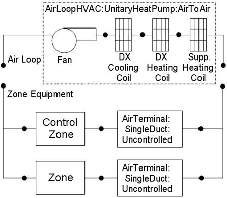
Figure 101. Schematic of EnergyPlus Unitary Air-to-Air Heat Pump (Blow Through Configuration)
Links to the fan, DX cooling coil, DX heating coil, and supplementary heating coil specifications are provided in the heat pump’s input data syntax. In addition the control zone name and the system design operating conditions are specified by the heat pump inputs.
This alpha field contains the identifying name for the unitary system heat pump.
This alpha field contains the schedule name (ref. Schedule) that contains information on the availability of the heat pump to operate. A schedule value greater than 0 (usually 1 is used) indicates that the unit can be on during the hour. A value less than or equal to 0 (usually 0 is used) denotes that the unit must be off for the hour.
This alpha field contains the name of the HVAC system node from which the heat pump draws its inlet air.
This alpha field contains the name of the HVAC system node to which the heat pump sends its outlet air.
This numeric field defines the supply air flow rate leaving the heat pump in cubic meters per second when the DX cooling coil is operating. Values must be greater than 0 or this field is autosizable.
This numeric field defines the supply air flow rate leaving the heat pump in cubic meters per second when the DX heating coil and/or supplemental heater are operating. Values must be greater than 0 or this field is autosizable.
This numeric field defines the supply air flow rate leaving the heat pump in cubic meters per second when neither cooling or heating is required (i.e., DX coils and supplemental heater are off but the supply air fan operates). This field is only used when the heat pump operating mode is specified as continuous fan operation. Values must be greater than or equal to zero, or this field is autosizable. If the heat pump operating mode is specified as continuous fan operation and this value is set to zero or this field is left blank, then the model assumes that the supply air flow rate when no cooling/heating is needed is equal to the supply air flow rate when the compressor was last operating (for cooling operation or heating operation).
This alpha field contains the identifying zone name where the thermostat controlling the heat pump is located.
This alpha field contains the identifying type of supply air fan specified for the heat pump. Fan type must be Fan:OnOff or Fan:ConstantVolume. Fan:ConstantVolume is used when the Supply Air Fan Operating Mode Schedule values are never 0 and the fan operates continuously. Fan:OnOff is used when the fan cycles on and off with the cooling or heating coil (i.e. Supply Air Fan Operating Mode Schedule values are at times 0).
This alpha field contains the identifying name given to the heat pump supply air fan, and should match the name specified in the corresponding fan object.
This alpha field contains the identifying type of heating coil specified in the heat pump. Heating coil type must be:
Coil:Heating:DX:SingleSpeed
This alpha field contains the identifying name given to the heat pump DX heating coil, and should match the name specified in the corresponding DX heating coil object.
This alpha field contains the identifying type of cooling coil specified in the heat pump. There are two valid choices for this field:
Coil:Cooling:DX:SingleSpeed
CoilSystem:Cooling:DX:HeatExchangerAssisted
This alpha field contains the identifying name given to the heat pump cooling coil, and should match the name specified in the corresponding DX cooling coil object.
This alpha field contains the identifying type of supplemental heating coil specified in the heat pump. Heating coil type must be:
Coil:Heating:Electric
Coil:Heating:Gas
This alpha field contains the identifying name given to the heat pump supplemental heating coil, and should match the name specified in the corresponding heating coil object.
This numeric field defines the maximum allowed supply air temperature exiting the heat pump supplemental heating coil.
This numeric field defines the outdoor air dry-bulb temperature above which the heat pump supplemental heating coil is disabled. The temperature for this input field must be less than or equal to 21 C. If this input field is left blank, the default value is 21 C.
This alpha field has two choices: BlowThrough or DrawThrough. The first choice represents a blow through system where the supply air fan is before the DX cooling/heating coil and the supplementary heating coil. The second choice represents a draw through system where the supply air fan is between the DX cooling/heating coil and the supplementary heating coil. If this input field is left blank, the default is blow through.
Field: Supply Air Fan Operating Mode Schedule Name
This alpha field specifies the name of the supply air fan operating mode schedule. The supply air fan operating mode may vary during the simulation based on time-of-day or with a change of season. Schedule values of 0 denote that the unitary system supply air fan and the heating or cooling coil cycle on and off together to meet the heating or cooling load (a.k.a. AUTO fan). Schedule values other than 0 denote that the supply fan runs continuously while the heating or cooling coil cycles to meet the load.
As shown in the example below, correct specification of the air-to-air heat pump requires specification of the following objects in addition to the heat pump object:
1) Fan (Fan:OnOff or Fan:ConstantVolume)
2) Heating coil (Coil:Heating:DX:SingleSpeed)
3) Cooling coil (Coil:Cooling:DX:SingleSpeed or CoilSystem:Cooling:DX:HeatExchangerAssisted)
4) Supplemental heating coil (Coil:Heating:Gas or Coil:Heating:Electric)
5) Direct air unit (AirTerminal:SingleDuct:Uncontrolled) for each zone served by the unitary system
This alpha input field contains the type of dehumidification control. The following options are valid for this field:
None - meet sensible load only, no active dehumidification control
Multimode - activate enhanced dehumidification mode as needed and meet sensible cooling load. This option is used to model DX equipment with a controllable heat exchanger assisting the DX cooling coil for improved dehumidification. It is valid only with cooling coil type = CoilSystem:Cooling:DX:HeatExchangerAssisted.
CoolReheat - cool beyond the dry-bulb temperature set point as required to meet the high humidity setpoint. The excess cooling beyond the cooling set point temperature is offset by the supplemental heating coil. If cooling coil type = CoilSystem:Cooling:DX:HeatExchangerAssisted, then the heat exchanger is assumed to always transfer energy between the cooling coil’s inlet and outlet airstreams when the cooling coil is operating.
The default is None. For the other dehumidification control modes, the maximum humidity setpoint is required. This must be set using a ZoneControl:Humidistat object. When extra dehumidification is required, the system may not be able to meet the humidity setpoint if its full capacity is not adequate. Supplemental heating coil (supplemental heating coil type and name) is a required input in AirToAir HeatPumps. The supplemental heating coil capacity must be adequate enough to meet the heating coil load and offset the excess cooling load due to extra dehumidification required to meet the high relative humidity setpoint.
Note: the air-to-air heat pump’s fan, cooling coil, heating coil and supplementary heating coil must be connected in the air loop according to the configuration shown above (Figure 101) for the blow-through fan configuration. The only other valid configuration is with a draw-through fan placement, where the fan is located between the DX heating coil and the supplementary heating coil. In addition, the volumetric air flow rate specified in the direct air unit for the controlling zone should properly reflect the fractional volumetric air flow rate specified in the heat pump object.
AirLoopHVAC:UnitaryHeatPump:AirToAir,
DXAC Heat Pump 1, ! Heat Pump name
FanAndCoilAvailSched, ! Heat Pump availability schedule
Mixed Air Node, ! Heat Pump air inlet node
Air Loop Outlet Node, ! Heat Pump air outlet node
1.3, !- Supply air volumetric flow rate during cooling operation {m3/s}
1.3, !- Supply air volumetric flow rate during heating operation {m3/s}
0.0, !- Design air volumetric flow rate when no heating or cooling is needed {m3/s}
East Zone, ! Controlling zone or thermostat location
Fan:OnOff, ! Supply air fan type
Supply Fan 1, ! Supply air fan name –- same name used in fan object
Coil:Heating:DX:SingleSpeed, ! Heating coil type
Heat Pump DX Heating Coil 1, ! Heating coil name –- same name used in DX heating coil object
Coil:Cooling:DX:SingleSpeed, ! Cooling coil type
Heat Pump ACDXCoil 1, ! Cooling coil name –- same name used in DX cooling coil object
Coil:Heating:Gas, ! Supplemental heating coil type
Heat Pump DX Supp Heating Coil 1, ! Supplemental heating coil name–- same as in heating coil object
50, ! Maximum supply air temperature from supplemental heater [C]
21, ! Maximum outdoor dry-bulb temp for supplemental heating coil operation [C]
BlowThrough, ! Fan placement
CycFanSchedule, ! Supply air fan operating mode schedule name
CoolReheat; !- Dehumidification Control Type
Coil:Heating:DX:SingleSpeed,
Heat Pump DX Heating Coil 1, ! Name of heating coil
FanAndCoilAvailSched, ! Heating coil schedule
35000, ! Rated total heating capacity [W] (at 21.11C/8.33C)
2.75, ! Rated heating COP
1.7, ! Rated air flow rate [m3/s]
Heating Coil Air Inlet Node, ! Coil air inlet node
SuppHeating Coil Air Inlet Node, ! Coil air outlet node
HPACHeatCapFT, ! Heating capacity modifier curve (temperature,C)
HPACHeatCapFFF, ! Heating capacity modifier curve (flow fraction)
HPACHeatEIRFT, ! Energy input ratio modifier curve (temperature,C)
HPACHeatEIRFFF, ! Energy input ratio modifier curve (flow fraction)
HPACCoolPLFFPLR, ! Part load fraction modifier curve (function of part-load ratio)
, ! defrost EIR modifier curve (temp, C) not required for resistive defrost
CyclingFanAndCompressor, ! Operation mode (cycling fan, cycling compressor)
-5.0, ! Minimum OAT for heat pump compressor operation [C]
5.0, ! Maximum outdoor dry-bulb temp for defrost operation [C]
200.0, ! Crankcase heater capacity[W]
10.0, ! Maximum OAT for crankcase heater operation [C]
resistive, ! Defrost strategy (resistive or reverse-cycle)
timed, ! Defrost control (timed or on-demand)
0.166667, !Defrost time period fraction (used for timed defrost control only)
20000; ! Resistive defrost heater capacity [W]
Coil:Cooling:DX:SingleSpeed,
Heat Pump ACDXCoil 1, ! Name of cooling coil
FanAndCoilAvailSched, ! Availability schedule
32000, ! Rated total cooling capacity [W]
0.75, ! Rated sensible heat ratio
3.0, ! Rated COP
1.7, ! Rated air flow rate [m3/s]
DX Cooling Coil Air Inlet Node, ! Coil air inlet node
Heating Coil Air Inlet Node, ! Coil air outlet node
HPACCoolCapFT, ! Cooling capacity modifier curve (temperature,C)
HPACCoolCapFFF, ! Cooling capacity modifier curve (flow fraction)
HPACCoolEIRFT, ! Energy input ratio modifier curve (temperature,C)
HPACCoolEIRFFF, ! Energy input ratio modifier curve (flow fraction)
HPACCoolPLFFPLR, ! Part load factor modifier curve (function of part-load ratio)
CyclingFanAndCompressor; ! Operation mode (cycling fan, cycling compressor)
Coil:Heating:Gas,
Heat Pump DX Supp Heating Coil 1, ! Name of heating coil
FanAndCoilAvailSched, ! Availability schedule
0.8 , ! Gas Burner Efficiency of the Coil
32000, ! Nominal Capacity of the Coil [W]
SuppHeating Coil Air Inlet Node, ! Supplementary heating coil air side inlet node
Air Loop Outlet Node; ! Supplementary heating coil air side outlet node
Fan:OnOff,
Supply Fan 1, ! Fan Name
FanAndCoilAvailSched, ! Fan Schedule
0.7, ! Fan Efficiency
300.0, ! Delta Pressure [N/M^2]
1.7, ! Max Vol Flow Rate [m^3/Sec]
0.9, ! motor efficiency
1.0, ! motor in air stream fraction
Mixed Air Node, ! fan inlet node
DX Cooling Coil Air Inlet Node; ! fan outlet node
AirTerminal:SingleDuct:Uncontrolled,
Zone1DirectAir, ! direct air unit name
FanAndCoilAvailSched, ! schedule name for on/off schedule
Zone 1 Inlet Node, ! zone supply air node name
0.612; ! maximum air flow rate, m3/s
AirTerminal:SingleDuct:Uncontrolled,
Zone2DirectAir, ! direct air unit name
FanAndCoilAvailSched, ! schedule name for on/off schedule
Zone 2 Inlet Node, ! zone supply air node name
0.476; ! maximum air flow rate, m3/s
AirTerminal:SingleDuct:Uncontrolled,
Zone3DirectAir, ! direct air unit name
FanAndCoilAvailSched, ! schedule name for on/off schedule
Zone 3 Inlet Node, ! zone supply air node name
0.612; ! maximum air flow rate, m3/s
HVAC, Average, Unitary Heat Pump Fan Part-Load Ratio
HVAC, Average, Unitary Heat Pump Compressor Part-Load Ratio
HVAC, Average, Heat Pump Dehumidification Induced Heating Demand Rate [W]
This output variable is the ratio of actual air mass flow rate through the heat pump to the heat pump’s design air mass flow rate (i.e., design volumetric flow rate converted to dry air mass flow rate). For continuous fan operation mode, this variable is always 1.0 when the furnace is available (based on the availability schedule). For cycling fan/cycling coil operation mode, the actual air mass flow rate is calculated based on the ratio of the sensible heating (or cooling) load to the steady-state heat pump heating (or cooling) capacity. For the cycling fan mode, the runtime fraction for the heat pump fan may be different from the fan part-load ratio reported here due the part-load performance of the heat pump’s heating (or cooling) coil (delay at start-up to reach steady-state output). In general, runtime fractions are reported by individual components where appropriate (e.g., Fan:OnOff).
This output variable is the ratio of the sensible load (heating or cooling) to the steady-state capacity of the heat pump’s DX heating or cooling coil. The runtime fraction for the heat pump compressor may be different from the compressor part-load ratio reported here due the part-load performance of the heating/cooling coil (delay at start-up to reach steady-state output). In general, runtime fractions are reported by individual components where appropriate.
This output variable is the additional heating demand rate of the supplemental heating coil of an Air-to-Air heat pumps in Watts. This additional heating demand is induced when zone air overshoots the heating setpoint due to extra dehumidification requirement to meet the high humidity setpoint. This value is always positive. This value is calculated for each HVAC system timestep, and the results are averaged for the timestep being reported.
The multispeed air-to-air heat pump is a “virtual” component that consists of a fan component (On/Off or ConstVolume), a DX multispeed cooling coil component, a DX multispeed heating coil component, and a Gas or Electric supplemental heating coil component. This system also includes the option to use available waste energy to heat water. A schematic diagram of the air-to-air multispeed heat pump is shown below. The component connection sequence for the blow through option (shown below) from inlet to outlet is fan, cooling coil, heating coil, and supplemental heater. The connection sequence for the draw through option is cooling coil, heating coil, fan, and supplemental heater.
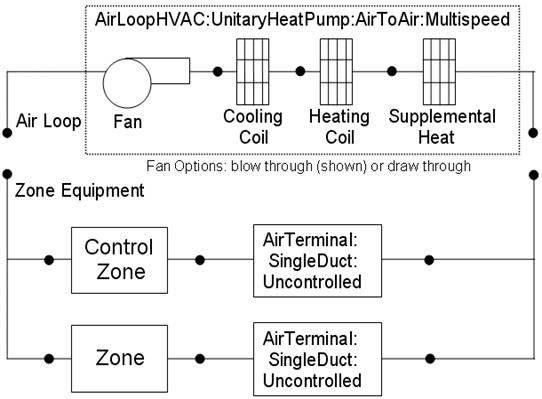
Figure 102. Schematic of EnergyPlus Unitary Air-to-Air Multi Speed Heat Pump
The main difference between this heat pump object and other EnergyPlus heat pump objects is that this object allows from two to four discrete compressor speeds for heating and cooling operation (instead of a single speed for each mode). The lowest speed is called Speed 1, and the highest speed is called Speed n (2, 3 or 4 as specified in the input syntax). This object allows a different number of speeds for cooling and heating, and each speed has an associated airflow rate. The airflow rates for the various heating speeds can be different from the airflow rates for the cooling speeds. In addition, the airflow rate when no cooling or heating is needed can also be defined. The number of cooling and heating speeds defined by the user in this heat pump object must equal the number of speeds defined in the associated coils (child objects). For example, the number of speeds for cooling defined in this heat pump object must be equal to the number of speeds defined in the associated cooling coil object.
Links to the fan, DX multispeed cooling coil, DX multispeed heating coil, and supplementary heating coil specifications are provided in the heat pump’s input data syntax. In addition, the control zone name and airflow rates at the corresponding compressor speeds are specified by the heat pump syntax.
This alpha field contains the identifying name for the multispeed heat pump.
This alpha field contains the schedule name (ref. Schedule) that contains information on the availability of the heat pump to operate. A schedule value greater than 0 (usually 1 is used) indicates that the unit can be on during the hour. A value less than or equal to 0 (usually 0 is used) denotes that the unit must be off for the hour.
This alpha field contains the name of the HVAC system node from which the heat pump draws its inlet air.
This alpha field contains the name of the HVAC system node to which the heat pump sends its outlet air.
This alpha field contains the identifying zone name where the thermostat controlling the multispeed heat pump is located.
This alpha field contains the identifying type of supply air fan specified for the heat pump. Fan type must be Fan:OnOff or Fan:ConstantVolume. Fan:ConstantVolume can only be used when the supply air fan operating mode is continuous (see field ‘Supply air fan operating mode schedule name).
This alpha field contains the identifying name given to the heat pump supply air fan, and should match the name specified in the corresponding fan object.
This alpha field has two choices: BlowThrough or DrawThrough. The first choice stands for “blow through fan”. This means that the unit consists of a fan followed by a DX multispeed cooling coil, DX multispeed heating coil, and a supplemental heating coil. The fan “blows through” the cooling and heating coils. The second choice stands for “draw through fan”. This means that the unit consists of the DX cooling and heating coils followed by a fan, with the supplemental heater located at the outlet of the fan. The fan “draws” air through the DX coils.
Note: the multispeed heat pump’s supply air fan, cooling coil, heating coil and supplemental heating coil must be connected according to the configuration shown above (Figure 102) for the ‘blow through’ fan configuration. For the ‘draw through’ fan configuration the fan must be located between the DX heating coil and the supplemental heater, whose outlet node is the system outlet node. In addition, the DX cooling coil and DX heating coil operation mode must be specified consistently with the heat pump’s supply air fan operating mode (e.g., with the heat pump’s supply air fan set to cycle on and off with the cooling/heating load, the DX cooling and heating coil operation mode must be CyclingFanAndCompressor). If the operation modes in the parent (heat pump) and child (coil) objects are specified differently, the operation mode in the parent object prevails.
This alpha field contains the schedule name (ref. Schedule) that contains information to control the supply air fan. Schedule values of zero mean that the supply air fan will cycle off if there is no cooling or heating load in the control zone. Non-zero schedule values mean that the supply air fan will operate continuously even if there is no cooling or heating load in the control zone. If this field is left blank, the supply air fan will operate continuously for the entire simulation period.
This alpha field contains the identifying type of heating coil specified in the heat pump. Heating coil type must be Coil:Heating:DX:MultiSpeed.
This alpha field contains the identifying name given to the DX heating coil, and should match the name specified in the corresponding DX heating coil object.
This numeric field defines the outdoor air dry-bulb temperature below which the DX heating coil turns off. The temperature for this input field must be greater than or equal to –20 C. If this input field is left blank, the default value is -8 C. This temperature should match the minimum compressor operating temperature specified for the multispeed heat pump’s DX heating coil.
This alpha field contains the identifying type of cooling coil specified in the heat pump. Cooling coil type must be Coil:Cooling:DX:MultiSpeed.
This alpha field contains the identifying name given to the heat pump cooling coil, and should match the name specified in the corresponding DX cooling coil object.
This alpha field contains the identifying type of supplemental heating coil specified in the heat pump. Heating coil type must be Coil:Gas:Heating or Coil:Electric:Heating.
This alpha field contains the identifying name given to the heat pump supplemental heating coil, and should match the name specified in the corresponding heating coil object.
This numeric field defines the maximum allowed supply air temperature (in degrees C) exiting the heat pump supplemental heating coil. If the calculated supply air temperature exiting the supplemental heater exceeds this value, then it is reset to this maximum temperature. This field is autosizable.
This numeric field defines the outdoor air dry-bulb temperature above which the heat pump supplemental heating coil is disabled. The temperature for this input field must be less than or equal to 21 C. If this input field is left blank, the default value is 21 C.
This field defines auxiliary electrical power (W) consumed during the on-cycle period (i.e., when the cooling or heating coil is operating). The model assumes that this auxiliary power does not contribute to heating the supply air. The minimum value for this field is 0.0, and the default value is also 0.0 if the field is left blank.
This field defines auxiliary electrical power (W) consumed during the off-cycle period (i.e., when the cooling and heating coil are not operating). The model assumes that this auxiliary power does not contribute to heating the supply air. The minimum value for this field is 0.0, and the default value is also 0.0 if the field is left blank.
This optional input field defines the design water flow rate used if the heat recovery option is being simulated. If this value is greater than 0.0 then a heat recovery loop must be specified and attached to the multispeed heat pump using the next 2 node fields. To determine how the heat recovery algorithm works, refer to the EnergyPlus Engineering Reference in the AirLoopHVAC:UnitaryHeatPump:AirToAir:MultiSpeed with Heat Recovery section. The units for this input value are cubic meters per second.
This field sets the maximum temperature (in degrees C) that this heat pump can produce for heat recovery. The idea behind this field is that the current models do not take temperatures into account for availability and they just pass Q's around the loop without a temperature limit. This temperature limit puts an upper bound on the recovered heat and limits the max temperature leaving the component.
As temperatures in the loop approach the maximum temperature, the temperature difference between the entering water and the surfaces in the piece of equipment becomes smaller. For the given heat recovery flow rate and that temperature difference the amount of heat recovered will be reduced, and eventually there will be no heat recovered when the entering water temperature is equal to the maximum temperature specified by the user in this field. The reduced amount of heat recovered will diminish if the temperature of the loop approach is the maximum temperature, and this will show up in the reporting. This allows the user to set the availability or the quality of the heat recovered for usage in other parts of the system or to heat domestic hot water supply.
This alpha field contains the identifying name for the heat recovery side inlet node.
This alpha field contains the identifying name for the heat recovery side outlet node.
This numeric field defines the supply air flow rate leaving the heat pump in cubic meters per second when neither cooling nor heating is required (i.e., DX coils and supplemental heater are off but the supply air fan operates). This field is only used when the heat pump supply air fan is scheduled to operate continuously regardless of DX coil operation (ref. field “Supply air fan operating mode schedule). Values must be greater than or equal to zero, or this field is autosizable. If the heat pump supply air fan is scheduled to operate continuously and the input value for this field is set to zero or this field is left blank, then the model assumes that the supply air flow rate when no cooling/heating is needed is equal to the supply air flow rate when the compressor was last operating (for cooling operation or heating operation).
This field defines the number of heating speeds for the heat pump, and must match the number of heating speeds defined in the associated heating coil. The value for this input field defines the number of airflow rates that must be defined for heating in the field below. The minimum value for this field is two and the maximum value is four.
This field defines the number of cooling speeds for the heat pump, and must match the number of cooling speeds defined in the associated DX cooling coil. The value for this input field defines the number of airflow rates that must be defined for cooling in the field below. The minimum value for this field is two and the maximum value is four.
This required numeric field defines the supply air flow rate leaving the heat pump in cubic meters per second when the DX heating coil and/or supplemental heater are operating at Speed 1 (lowest speed). Values must be greater than 0 or this field is autosizable.
This required numeric field defines the supply air flow rate leaving the heat pump in cubic meters per second when the DX heating coil and/or supplemental heater are operating at Speed 2. Values must be greater than 0 or this field is autosizable. If not autosized, the entered value must be greater or equal to the flow rate specified for heating Speed 1.
This numeric field defines the supply air flow rate leaving the heat pump in cubic meters per second when the DX heating coil and/or supplemental heater are operating at Speed 3. Values must be greater than 0 or this field is autosizable. If not autosized, the entered value must be greater or equal to the flow rate specified for heating Speed 2. If the ‘Number of Speeds for Heating’ is less than 3, then this field can be left blank.
This numeric field defines the supply air flow rate leaving the heat pump in cubic meters per second when the DX heating coil and/or supplemental heater are operating at Speed 4 (high speed). Values must be greater than 0 or this field is autosizable. If not autosized, the entered value must be greater or equal to the flow rate specified for heating Speed 3. If the ‘Number of Speeds for Heating’ is less than 4, then this field can be left blank.
Note: When autosizable is selected for any of the supply air volumetric flow rate fields, all supply air flow fields at the different speeds must be specified as autosizable. Otherwise, a fatal error will be issued and the simulation will terminate.
This required numeric field defines the supply air flow rate leaving the heat pump in cubic meters per second when the DX cooling coil is operating at Speed 1 (lowest speed). Values must be greater than 0 or this field is autosizable.
This required numeric field defines the supply air flow rate leaving the heat pump in cubic meters per second when the DX cooling coil is operating at Speed 2. Values must be greater than 0 or this field is autosizable. If not autosized, the entered value must be greater or equal to the flow rate specified for cooling Speed 1.
This numeric field defines the supply air flow rate leaving the heat pump in cubic meters per second when the DX cooling coil is operating at Speed 3. Values must be greater than 0 or this field is autosizable. If not autosized, the entered value must be greater or equal to the flow rate specified for cooling Speed 2. If the ‘Number of Speeds for Cooling’ is less than 3, then this field can be left blank.
This numeric field defines the supply air flow rate leaving the heat pump in cubic meters per second when the DX cooling coil is operating at Speed 4 (highest speed). Values must be greater than 0 or this field is autosizable. If not autosized, the entered value must be greater or equal to the flow rate specified for cooling Speed 3. If the ‘Number of Speeds for Cooling’ is less than 4, then this field can be left blank.
Following is an example input for the object and its associated components.
AirLoopHVAC:UnitaryHeatPump:AirToAir:MultiSpeed,
DXAC Heat Pump 1, !- Name of multispeed heat pump
FanAndCoilAvailSched, !- Availability schedule
Mixed Air Node, !- Heat pump air inlet node name
Air Loop Outlet Node, !- Heat pump air outlet node name
East Zone, !- Controlling zone or thermostat location
Fan:OnOff, !- Supply air fan type
Supply Fan 1, !- Supply air fan name
BlowThrough, !- Supply air fan placement
FanModeSchedule, !- Supply air fan operating mode schedule name
Coil:Heating:DX:MultiSpeed, Heat Pump DX Heating Coil 1, !- Heating coil type & name
-8.0, !- Minimum outdoor dry-bulb temperature for compressor operation
Coil:Cooling:DX:MultiSpeed, Heat Pump ACDXCoil 1, !- Cooling coil type & name
Coil:Heating:Gas, !- Supplemental heating coil type
Supp Gas Heating Coil 1, !- Supplemental heating coil name
50.0, !- Maximum supply air temperature from supplemental heater
21, !- Maximum outdoor dry-bulb temperature for supplemental heater operation
0, !- Auxiliary On-Cycle Electric Power {W}
0, !- Auxiliary Off-Cycle Electric Power {W}
0.00, !- Design Heat Recovery Water Flow Rate {m3/s}
80.0,,, !- Maximum Temp for Heat Recovery {C} & Node names (none)
0.2, !- Supply air volumetric flow rate when no cooling or heating is needed
4, !- Number of speeds for heating
4, !- Number of speeds for cooling
0.4, !- Supply air flow rate during heating operation, Speed 1
0.8, !- Supply air flow rate during heating operation, Speed 2
1.2, !- Supply air flow rate during heating operation, Speed 3
1.7, !- Supply air flow rate during heating operation, Speed 4
0.4, !- Supply air flow rate during cooling operation, Speed 1
0.8, !- Supply air flow rate during cooling operation, Speed 2
1.2, !- Supply air flow rate during cooling operation, Speed 3
1.7; !- Supply air flow rate during cooling operation, Speed 4
Coil:Heating:DX:MultiSpeed,
Heat Pump DX Heating Coil 1, !- Name of heat pump heating coil
FanAndCoilAvailSched, !- Availability Schedule
Heating Coil Air Inlet Node, !- Coil Air Inlet Node
SuppHeating Coil Air Inlet Node, !- Coil Air Outlet Node
CyclingFanAndCompressor, !- Supply Air Fan Operation Mode
-8.0, !- Minimum Outdoor Dry-bulb Temperature for Compressor Operation {C}
200.0, !- Crankcase Heater Capacity {W}
10.0, !- Maximum Outdoor Dry-bulb Temperature for Crankcase Heater
!- Operation {C}
HPACDefrostCAPFT, !- Defrost energy input ratio modifier curve (temperature)
7.22, !- Maximum Outdoor Dry-bulb Temperature for Defrost Operation
reverse-cycle, !- Defrost Strategy
timed, !- Defrost Control
0.058333, !- Defrost Time Period Fraction
2000.0, !- Resistive Defrost Heater Capacity {W}
No, !- Apply Part Load Fraction to Speeds greater than 1
NaturalGas, !- Fuel type
4, !- Number of speeds
7500, !- Rated Total Heating Capacity, Speed 1 {W}
2.75, !- Rated COP, Speed 1
0.45, !- Rated Air Volume Flow Rate, Speed 1 {m3/s}
HPACHeatCapFT Speed 1, !- Total Heating Capacity Modifier Curve, Speed 1 (temperature)
HPACHeatCapFF Speed 1, !- Total Heating capacity modifier curve, Speed 1 (flow fraction)
HPACHeatEIRFT Speed 1, !- Energy input ratio modifier curve, Speed 1 (temperature)
HPACHeatEIRFF Speed 1, !- Energy input ratio modifier curve, Speed 1 (flow fraction)
HPACHeatPLFFPLR Speed 1, !- Part load fraction correlation, Speed 1 (part load ratio)
0.2, !- Rated waste heat fraction of power input, Speed 1
HAPCHeatWHFT Speed 1, !- Waste heat modifier curve, Speed 1 (temperature)
17500, !- Rated Total Heating Capacity, Speed 2 {W}
2.75, !- Rated COP, Speed 2
0.85, !- Rated Air Volume Flow Rate, Speed 2 {m3/s}
HPACHeatCapFT Speed 2, !- Total Heating Capacity Modifier Curve, Speed 2 (temperature)
HPACHeatCapFF Speed 2, !- Total Heating capacity modifier curve, Speed 2 (flow fraction)
HPACHeatEIRFT Speed 2, !- Energy input ratio modifier curve, Speed 2 (temperature)
HPACHeatEIRFF Speed 2, !- Energy input ratio modifier curve, Speed 2 (flow fraction)
HPACHeatPLFFPLR Speed 2, !- Part load fraction correlation, Speed 2 (part load ratio)
0.2, !- Rated waste heat fraction of power input, Speed 2
HAPCHeatWHFT Speed 2, !- Waste heat modifier curve, Speed 2 (temperature)
25500, !- Rated Total Heating Capacity, Speed 3 {W}
2.75, !- Rated COP, Speed 3
1.25, !- Rated Air Volume Flow Rate, Speed 3 {m3/s}
HPACHeatCapFT Speed 3, !- Total Heating Capacity Modifier Curve, Speed 3 (temperature)
HPACHeatCapFF Speed 3, !- Total Heating capacity modifier curve, Speed 3 (flow fraction)
HPACHeatEIRFT Speed 3, !- Energy input ratio modifier curve, Speed 3 (temperature)
HPACHeatEIRFF Speed 3, !- Energy input ratio modifier curve, Speed 3 (flow fraction)
HPACHeatPLFFPLR Speed 3, !- Part load fraction correlation, Speed 3 (part load ratio)
0.2, !- Rated waste heat fraction of power input, Speed 3
HAPCHeatWHFT Speed 3, !- Waste heat modifier curve, Speed 3 (temperature)
35500, !- Rated Total Heating Capacity, Speed 4 {W}
2.75, !- Rated COP, Speed 4
1.75, !- Rated Air Volume Flow Rate, Speed 4 {m3/s}
HPACHeatCapFT Speed 4, !- Total Heating Capacity Modifier Curve, Speed 4 (temperature)
HPACHeatCapFF Speed 4, !- Total Heating capacity modifier curve, Speed 4 (flow fraction)
HPACHeatEIRFT Speed 4, !- Energy input ratio modifier curve, Speed 4 (temperature)
HPACHeatEIRFF Speed 4, !- Energy input ratio modifier curve, Speed 4 (flow fraction)
HPACHeatPLFFPLR Speed 4, !- Part load fraction correlation, Speed 4 (part load ratio)
0.2, !- Rated waste heat fraction of power input, Speed 4
HAPCHeatWHFT Speed 4; !- Waste heat modifier curve, Speed 4 (temperature)
COIL:Cooling:DX:MultiSpeed,
Heat Pump ACDXCoil 1, !- Coil Name
FanAndCoilAvailSched, !- Availability Schedule
DX Cooling Coil Air Inlet Node, !- Coil Air Inlet Node
Heating Coil Air Inlet Node, !- Coil Air Outlet Node
CyclingFanAndCompressor, !- Supply Air Fan Operation Mode
Outdoor Condenser Air Node, !- Condenser Air Inlet Node Name
AirCooled, !- Condenser Type
, !- Name of Water Storage Tank for Supply
, !- Name of Water Storage Tank for Condensate Collection
No, !- Apply Part Load Fraction to Speeds greater than 1
No, !- Apply Latent Degradation to Speeds greater than 1
200.0, !- Crankcase Heater Capacity {W}
10.0, !- Maximum Outdoor Dry-bulb Temperature for Crankcase Heater
!- Operation {C}
NaturalGas, !- Fuel type
4, !- Number of speeds
7500, !- Rated Total Cooling Capacity, Speed 1 (gross) {W}
0.75, !- Rated SHR, Speed 1
3.0, !- Rated COP, Speed 1
0.40, !- Rated Air Volume Flow Rate, Speed 1 {m3/s}
HPACCoolCapFT Speed 1, !- Total Cooling Capacity Modifier Curve, Speed 1 (temperature)
HPACCoolCapFF Speed 1, !- Total Cooling Capacity Modifier Curve, Speed 1 (flow fraction)
HPACCOOLEIRFT Speed 1, !- Energy Input Ratio Modifier Curve, Speed 1 (temperature)
HPACCOOLEIRFF Speed 1, !- Energy Input Ratio Modifier Curve, Speed 1 (flow fraction)
HPACCOOLPLFFPLR Speed 1, !- Part Load Fraction Correlation, Speed 1 (part load ratio)
1000.0, !- Nominal Time for Condensate Removal to Begin, Speed 1 {s}
1.5, !- Ratio of Initial Moisture Evaporation Rate and Steady-state Latent
!- Capacity, Speed 1 {dimensionless}
3.0, !- Maximum ON/OFF Cycling Rate, Speed 1 {cycles/hr}
45.0, !- Latent Capacity Time Constant, Speed 1 {s}
0.2, !- Rated waste heat fraction of power input, Speed 1 {dimensionless}
HAPCCoolWHFT Speed 1, !- Waste heat modifier curve, Speed 1 (temperature)
0.9, !- Evaporative Condenser Effectiveness, Speed 1 {dimensionless}
0.05, !- Evaporative Condenser Air Volume Flow Rate, Speed 1 {m3/s}
50, !- Evaporative Condenser Pump Rated Power Consumption, Speed 1 {W}
17500, !- Rated Total Cooling Capacity, Speed 2 (gross) {W}
0.75, !- Rated SHR, Speed 2
3.0, !- Rated COP, Speed 2
0.85, !- Rated Air Volume Flow Rate, Speed 2 {m3/s}
HPACCoolCapFT Speed 2, !- Total Cooling Capacity Modifier Curve, Speed 2 (temperature)
HPACCoolCapFF Speed 2, !- Total Cooling Capacity Modifier Curve, Speed 2 (flow fraction)
HPACCOOLEIRFT Speed 2, !- Energy Input Ratio Modifier Curve, Speed 2 (temperature)
HPACCOOLEIRFF Speed 2, !- Energy Input Ratio Modifier Curve, Speed 2 (flow fraction)
HPACCOOLPLFFPLR Speed 1, !- Part Load Fraction Correlation, Speed 2 (part load ratio)
1000.0, !- Nominal Time for Condensate Removal to Begin, Speed 2 {s}
1.5, !- Ratio of Initial Moisture Evaporation Rate and Steady-state Latent
!- Capacity, Speed 2 {dimensionless}
3.0, !- Maximum ON/OFF Cycling Rate, Speed 2 {cycles/hr}
45.0, !- Latent Capacity Time Constant, Speed 2 {s}
0.2, !- Rated waste heat fraction of power input, Speed 2 {dimensionless}
HAPCCoolWHFT Speed 2, !- Waste heat modifier curve, Speed 2 (temperature)
0.9, !- Evaporative Condenser Effectiveness, Speed 2 {dimensionless}
0.1, !- Evaporative Condenser Air Volume Flow Rate, Speed 2 {m3/s}
60, !- Evaporative Condenser Pump Rated Power Consumption, Speed 2 {W}
25500, !- Rated Total Cooling Capacity, Speed 3 (gross) {W}
0.75, !- Rated SHR, Speed 3
3.0, !- Rated COP, Speed 3
1.25, !- Rated Air Volume Flow Rate, Speed 3 {m3/s}
HPACCoolCapFT Speed 3, !- Total Cooling Capacity Modifier Curve, Speed 3 (temperature)
HPACCoolCapFF Speed 3, !- Total Cooling Capacity Modifier Curve, Speed 3 (flow fraction)
HPACCOOLEIRFT Speed 3, !- Energy Input Ratio Modifier Curve, Speed 3 (temperature)
HPACCOOLEIRFF Speed 3, !- Energy Input Ratio Modifier Curve, Speed 3 (flow fraction)
HPACCOOLPLFFPLR Speed 1, !- Part Load Fraction Correlation, Speed 3 (part load ratio)
1000.0, !- Nominal Time for Condensate Removal to Begin, Speed 3 {s}
1.5, !- Ratio of Initial Moisture Evaporation Rate and Steady-state Latent
!- Capacity, Speed 3 {dimensionless}
3.0, !- Maximum ON/OFF Cycling Rate, Speed 3 {cycles/hr}
45.0, !- Latent Capacity Time Constant, Speed 3 {s}
0.2, !- Rated waste heat fraction of power input, Speed 3 {dimensionless}
HAPCCoolWHFT Speed 3, !- Waste heat modifier curve, Speed 3 (temperature)
0.9, !- Evaporative Condenser Effectiveness, Speed 3 {dimensionless}
0.2, !- Evaporative Condenser Air Volume Flow Rate, Speed 3 {m3/s}
80, !- Evaporative Condenser Pump Rated Power Consumption, Speed 3 {W}
35500, !- Rated Total Cooling Capacity, Speed 4 (gross) {W}
0.75, !- Rated SHR, Speed 4
3.0, !- Rated COP, Speed 4
1.75, !- Rated Air Volume Flow Rate, Speed 4 {m3/s}
HPACCoolCapFT Speed 4, !- Total Cooling Capacity Modifier Curve, Speed 4 (temperature)
HPACCoolCapFF Speed 4, !- Total Cooling Capacity Modifier Curve, Speed 4 (flow fraction)
HPACCOOLEIRFT Speed 4, !- Energy Input Ratio Modifier Curve, Speed 4 (temperature)
HPACCOOLEIRFF Speed 4, !- Energy Input Ratio Modifier Curve, Speed 4 (flow fraction)
HPACCOOLPLFFPLR Speed 1, !- Part Load Fraction Correlation, Speed 4 (part load ratio)
1000.0, !- Nominal Time for Condensate Removal to Begin, Speed 4 {s}
1.5, !- Ratio of Initial Moisture Evaporation Rate and Steady-state Latent
!- Capacity, Speed 4 {dimensionless}
3.0, !- Maximum ON/OFF Cycling Rate, Speed 4 {cycles/hr}
45.0, !- Latent Capacity Time Constant, Speed 4 {s}
0.2, !- Rated waste heat fraction of power input, Speed 4 {dimensionless}
HAPCCoolWHFT Speed 4, !- Waste heat modifier curve, Speed 4 (temperature)
0.9, !- Evaporative Condenser Effectiveness, Speed 4 {dimensionless}
0.3, !- Evaporative Condenser Air Volume Flow Rate, Speed 4 {m3/s}
100; !- Evaporative Condenser Pump Rated Power Consumption, Speed 4 {W}
Coil:Heating:Gas,
Supp Gas Heating Coil 1, !- Coil Name
FanAndCoilAvailSched, !- Available Schedule
0.8, !- Gas Burner Efficiency of the Coil
45000, !- Nominal Capacity of the Coil {W}
SuppHeating Coil Air Inlet Node, !- Coil_Air_Inlet_Node
Air Loop Outlet Node; !- Coil_Air_Outlet_Node
Fan:OnOff,
Supply Fan 1, !- Fan Name
FanAndCoilAvailSched, !- Available Schedule
0.7, !- Fan Total Efficiency
300.0, !- Delta Pressure {Pa}
1.7, !- Max Flow Rate {m3/s}
0.9, !- Motor Efficiency
1.0, !- Motor In Airstream Fraction
Mixed Air Node, !- Fan_Inlet_Node
DX Cooling Coil Air Inlet Node; !- Fan_Outlet_Node
AirTerminal:SingleDuct:Uncontrolled,
Zone1DirectAir, ! direct air unit name
FanAndCoilAvailSched, ! schedule name for on/off schedule
Zone 1 Inlet Node, ! zone supply air node name
0.612; ! maximum air flow rate, m3/s
AirTerminal:SingleDuct:Uncontrolled,
Zone2DirectAir, ! direct air unit name
FanAndCoilAvailSched, ! schedule name for on/off schedule
Zone 2 Inlet Node, ! zone supply air node name
0.476; ! maximum air flow rate, m3/s
AirTerminal:SingleDuct:Uncontrolled,
Zone3DirectAir, ! direct air unit name
FanAndCoilAvailSched, ! schedule name for on/off schedule
Zone 3 Inlet Node, ! zone supply air node name
0.612; ! maximum air flow rate, m3/s
HVAC,Average,Unitary MSHP Fan Part-Load Ratio
HVAC,Average,Unitary MSHP Compressor Part-Load Ratio
HVAC,Average,Unitary MSHP DX Coil Cycling Ratio
HVAC,Average,Unitary MSHP DX Coil Speed Ratio
HVAC,Average,Unitary MSHP DX Coil Speed Number
HVAC,Average,Unitary MSHP Electric Power[W]
HVAC,Sum,Unitary MSHP Electricity Energy Consumption[J]
HVAC,Average,Unitary MSHP Total Cooling Energy Rate [W]
HVAC,Average,Unitary MSHP Total Heating Energy Rate [W]
HVAC,Average,Unitary MSHP Sensible Cooling Energy Rate [W]
HVAC,Average,Unitary MSHP Sensible Heating Energy Rate [W]
HVAC,Average,Unitary MSHP Latent Cooling Energy Rate [W]
HVAC,Average,Unitary MSHP Latent Heating Energy Rate [W]
HVAC,Average,Unitary MSHP Auxiliary Electric Power[W]
HVAC,Sum,Unitary MSHP Auxiliary Electric Cooling Consumption[J]
HVAC,Sum,Unitary MSHP Auxiliary Electric Heating Consumption[J]
If heat recovery is specified:
HVAC,Average, Unitary MSHP Waste Heat Recovery Rate[W]
HVAC,Average, Unitary MSHP Waste Heat Recovery Inlet Temp[C]
HVAC,Average, Unitary MSHP Waste Heat Recovery Outlet Temp[C]
HVAC,Average, Unitary MSHP Waste Heat Recovery Mass Flow Rate[kg/s]
HVAC,Sum, Unitary MSHP Waste Heat Recovery Energy[J]
This output variable is the ratio of actual air mass flow rate through the multispeed heat pump to the heat pump’s design air mass flow rate (i.e., design volumetric flow rate converted to dry air mass flow rate) at Speed 1. For continuous fan operation mode, this variable is always 1.0 when the heat pump is available (based on the availability schedule). For cycling fan/cycling coil operation mode, the actual air mass flow rate is calculated based on the ratio of the sensible heating (or cooling) load to the steady-state heat pump heating (or cooling) capacity. For the cycling fan mode, the runtime fraction for the heat pump fan may be different from the fan part-load ratio reported here due the part-load performance of the heat pump’s heating (or cooling) coil (delay at start-up to reach steady-state output). In general, runtime fractions are reported by individual components where appropriate (e.g., Fan:OnOff). When the speed number is greater than 1, the value is 1.0.
This output variable is the ratio of the sensible load (heating or cooling) to the steady-state capacity of the multispeed heat pump’s DX heating or cooling coil at Speed 1. The runtime fraction for the heat pump compressor may be different from the compressor part-load ratio reported here due the part-load performance of the heating/cooling coil (delay at start-up to reach steady-state output). In general, runtime fractions are reported by individual components where appropriate. When the speed number is greater than 1, the value is 1.0.
This output variable is the ratio of the sensible load (heating or cooling) to the steady-state capacity of the multispeed heat pump’s DX heating or cooling coil (Speed 1) for the entire system timestep. The value is between 0.0 and 1.0 when the heat pump is cycling on and off its lowest speed (Speed 1) and 1.0 when the multispeed heat pump operates at speeds above 1.
This output variable is the ratio of time in a system timestep that the compressor is at rated speed between two consecutive speed numbers ( [Compressor Speed - Compressor speed at Speed i-1] / [Compressor speed at Speed i - Compressor speed at Speed i-1]). The compressor speed ratio reports (1.0 is max, 0.0 is min) and any value in between as it is averaged over the timestep. The value is 0.0 during Speed 1 operation.
The physical meaning of the speed ratio is dependent on the compressor configuration defined in the field of child coil object: Apply Part Load Fraction to Speeds greater than 1. The allowed choice is either Yes or No. When No is entered, one compressor is assumed for all speeds. The speed ratio represents how long the higher speed runs as a fraction of the system timestep, and the lower speed runs in the rest of the system timestep. When Yes is entered, multiple compressors are assumed, and each compressor has associated speed. The speed ratio represents how long the higher speed runs as a fraction of the system timestep, and the low speed runs in a whole system timestep.
This output variable reports the maximum speed needed when the heat pump operates to meet the sensible load (heating or cooling) in a system timestep. When the value is 1, the heat pump operates at Speed 1 (lowest speed). For this case the cycling ratio is between 0.0 and 1.0, while the speed ratio is 0.0. When the speed number output variable is above one, such as i, the heat pump operation is determined by the speed ratio through linear interpolation. For example, when the speed ratio is 0.4 and the speed number is 3, the heat pump operates at Speed 3 for 40% of a system timestep and at Speed 2 for 60% of a system timestep for a single compressor. For multiple compressors, the heat pump operates at Speed 3 in the 40% of a system timestep and at Speed 2 in the whole system timestep.
This output field is the total (enthalpy) heat addition rate of the multispeed heat pump to the zones it is serving in Watts. This value is calculated using the enthalpy difference of the heat pump outlet air and inlet air streams, and the air mass flow rate through the heat pump. This value is calculated for each HVAC system timestep being simulated, and the results (enthalpy addition only) are averaged for the timestep being reported.
This output field is the total (enthalpy) heat extraction rate of the multispeed heat pump from the zones it is serving in Watts. This value is calculated using the enthalpy difference of the heat pump outlet air and inlet air streams, and the air mass flow rate through the heat pump. This value is calculated for each HVAC system timestep being simulated, and the results (enthalpy extraction only) are averaged for the timestep being reported.
This output field reports the sensible heat addition rate of the multispeed heat pump to the zones it is serving in Watts. This value is calculated using the enthalpy difference of the heat pump outlet air and inlet air streams at a constant humidity ratio, and the air mass flow rate through the heat pump. This value is calculated for each HVAC system timestep being simulated, and the results (heating only) are averaged for the timestep being reported.
This output field reports the moist air sensible heat extraction rate of the multispeed heat pump from the zones it is serving in Watts. This value is calculated using the enthalpy difference of the heat pump outlet air and inlet air streams at a constant humidity ratio, and the air mass flow rate through the heat pump. This value is calculated for each HVAC system timestep being simulated, and the results (cooling only) are averaged for the timestep being reported.
This output field is the latent heat addition (humidification) rate of the multispeed heat pump in Watts. This value is calculated as the difference between the total energy rate and the sensible energy rate provided by the multispeed heat pump. This value is calculated for each HVAC system timestep being simulated, and the results (latent heat addition only) are averaged for the timestep being reported.
This output field is the latent heat extraction (dehumidification) rate of the multispeed heat pump in Watts. This value is calculated as the difference between the total energy rate and the sensible energy rate provided by the multispeed heat pump. This value is calculated for each HVAC system timestep being simulated, and the results (latent heat extraction only) are averaged for the timestep being reported.
This output field is the electricity consumption rate of the multispeed heat pump in Watts. The consumption includes electricity used by the DX coils (including crankcase heater if the fuel type is electricity), fans (indoor supply air fan and the condenser fans associated with the DX coil[s]), auxiliary power during on and off period, and the supplemental heating coil (if electric). This value is calculated for each HVAC system timestep being simulated, and the results are averaged for the timestep being reported. Any non-electric energy use is not reported by the heat pump object but is reported in the associated coil objects as appropriate.
This output field is the electricity consumption of the multispeed heat pump in Joules for the timestep being reported. The consumption includes electricity used by the DX compressor (including crankcase heater if the fuel type is electricity), fans (indoor supply air fan and the condenser fans associated with the DX coil[s]), auxiliary power during on and off period, and the supplemental heating coil (if electric). This value is calculated for each HVAC system timestep being simulated, and the results are summed for the timestep being reported. Any non-electric energy use is not reported by the heat pump object but is reported in the associated coil objects as appropriate.
This output field is the average auxiliary electricity consumption rate (including both on-cycle and off-cycle) in Watts for the timestep being reported.
This is the auxiliary electricity consumption in Joules for the timestep being reported. This is the auxiliary electricity consumption during periods when the heat pump is providing cooling (DX cooling coil is operating). This output is also added to a report meter with Resource Type = Electricity, End Use Key =Cooling, Group Key = System (ref. Report Meter).
This is the auxiliary electricity consumption in Joules for the timestep being reported. This is the auxiliary electricity consumption during periods when the heat pump is providing heating (DX heating coil is operating). This output is also added to a report meter with Resource Type = Electricity, End Use Key =Heating, Group Key = System (ref. Report Meter).
These outputs are the heat recovery inlet and outlet temperatures and water mass flow rate for multispeed heat pumps with heat recovery.
For multispeed heat pumps with heat recovery, these outputs are the recoverable energy rate (in Watts) and energy (in Joules).
The EnergyPlus furnace is a “virtual” component that consists of a fan component (OnOff or ConstantVolume) and a Gas or Electric heating coil component. The blow through furnace configuration is shown in the Figure below.
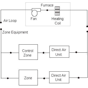
Figure 103. Schematic of Blow Through Furnace Model
Links to the fan and heating coil specifications are provided in the furnace input data syntax. In addition the control zone name and the furnace design operating conditions are specified by the furnace inputs.
This alpha field contains the identifying name for the furnace.
This alpha field contains the schedule name which contains information on the availability of the furnace to operate.
This alpha field contains the furnace inlet node name.
This alpha field contains the furnace outlet node name.
Field: Supply Air Fan Operating Mode Schedule Name
This alpha field specifies the name of the supply air fan operating mode schedule. The supply air fan operating mode may vary during the simulation based on time-of-day or with a change of season. Schedule values of 0 denote that the furnace supply air fan and the heating coil cycle on and off together to meet the heating load (a.k.a. AUTO fan). Schedule values other than 0 denote that the supply fan runs continuously while the heating coil cycles to meet the load.
This numeric field contains the design operating furnace air outlet temperature in degrees C when the furnace is heating. If this input field is left blank, the default value is 80 C.
This numeric field contains the design volumetric flow rate of the furnace in cubic meters per second. This volumetric flow rate should match the flow rate specified for the furnace fan.
This alpha field contains the identifying zone name where the thermostat controlling the furnace is located.
This alpha field contains the identifying type of supply air fan specified for the furnace. Fan type must be Fan:OnOff or Fan:ConstantVolume. Fan:ConstantVolume is used when the Supply Air Fan Operating Mode Schedule values are never 0 and the fan operates continuously. Fan:OnOff is used when the fan cycles on and off with the cooling or heating coil (i.e. Supply Air Fan Operating Mode Schedule values are at times 0).
This alpha field contains the identifying name given to the furnace fan.
This alpha field has two choices: BlowThrough or DrawThrough. The first choice stands for “blow through fan”. This means that the unit consists of a fan followed by the heating coil. The fan “blows through” the heating coil. The second choice stands for “draw through fan”. This means that the unit consists of the heating coil followed by a fan. The fan “draws air through” the heating coil. If this field is left blank, the default is blow through.
This alpha field contains the identifying type of heating coil specified in the furnace. Heating coil type must be:
Coil:Heating:Electric
Coil:Heating:Gas
This alpha field contains the identifying name given to the furnace heating coil.
As shown in the example below, correct specification of the furnace requires specification of the following objects in addition to the furnace object:
1) fan (Fan:OnOff or Fan:ConstantVolume)
2) heating coil (Coil:Heating:Gas or Coil:Heating:Electric)
3) direct air unit (AirTerminal:SingleDuct:Uncontrolled) for each zone served by the furnace
Note: the furnace’s fan and heating coil must be connected in the air loop according to the configuration shown above (Figure 103) when a blow through fan configuration is specified. If a draw through fan is used, the fan is located down stream of the heating coil. In addition, the volumetric air flow rate specified in the direct air unit for the controlling zone should properly reflect the fractional volumetric air flow rate specified in the furnace object.
AirLoopHVAC:Unitary:Furnace:HeatOnly,
Gas Furnace 1, !- Name
FanAndCoilAvailSched, !- Availability Schedule Name
Air Loop Inlet Node, !- Furnace Air Inlet Node Name
Air Loop Outlet Node, !- Furnace Air Outlet Node Name
CycFanSchedule, !- Supply Air Fan Operating Mode Schedule Name
80, !- Maximum Supply Air Temperature {C}
1.3, !- Supply Air Flow Rate {m3/s}
East Zone, !- Controlling Zone or Thermostat Location
Fan:OnOff, !- Supply Fan Object Type
Supply Fan 1, !- Supply Fan Fame
BlowThrough, !- Fan Placement
Coil:Heating:Gas, !- Heating Coil Object Type
Furnace Coil; !- Heating Coil Name
Coil:Heating:Gas,
Furnace Coil, !- Coil Name
FanAndCoilAvailSched, !- Available Schedule Name
0.8, !- Gas Burner Efficiency of the Coil
20000, !- Nominal Capacity of the Coil {W}
Heating Coil Air Inlet Node, !- Coil_Air_Inlet_Node
Air Loop Outlet Node, !- Coil_Air_Outlet_Node
, !- Coil_Temp_Setpoint_Node
100, !- Parasitic Electric Load {W}
PLFCurveforGasFurnace, !- Part load fraction correlation (function of part load ratio)
10; !- Parasitic Gas Load {W}
Curve:Cubic,
PLFCurveforGasFurnace, !- Name
0.8, !- Coefficient1 Constant
0.2, !- Coefficient2 x
0.0, !- Coefficient3 x**2
0.0, !- Coefficient4 x**3
0, !- Minimum Value of x
1; !- Maximum Value of x
Fan:OnOff,
Supply Fan 1, !- Fan Name
FanAndCoilAvailSched, !- Available Schedule
0.7, !- Fan Total Efficiency
600.0, !- Delta Pressure {Pa}
1.3, !- Max Flow Rate {m3/s}
0.9, !- Motor Efficiency
1.0, !- Motor In Airstream Fraction
Air Loop Inlet Node, !- Fan_Inlet_Node
Heating Coil Air Inlet Node; !- Fan_Outlet_Node
AirTerminal:SingleDuct:Uncontrolled,
Zone1DirectAir, !- Direct Air Name
FanAndCoilAvailSched, !- Schedule name for on/off schedule
Zone 1 Inlet Node, !- Zone Supply Air Node Name
0.47; !- Maximum air flow rate {m3/s}
AirTerminal:SingleDuct:Uncontrolled,
Zone2DirectAir, !- Direct Air Name
FanAndCoilAvailSched, !- Schedule name for on/off schedule
Zone 2 Inlet Node, !- Zone Supply Air Node Name
0.36; !- Maximum air flow rate {m3/s}
AirTerminal:SingleDuct:Uncontrolled,
Zone3DirectAir, !- Direct Air Name
FanAndCoilAvailSched, !- Schedule name for on/off schedule
Zone 3 Inlet Node, !- Zone Supply Air Node Name
0.47; !- Maximum air flow rate {m3/s}
Example of Heat-Only Furnace Specification
HVAC,Average,Furnace Fan Part-Load Ratio
This output variable is the ratio of actual air mass flow rate through the furnace to the furnace’s design air mass flow rate (i.e., design volumetric flow rate converted to dry air mass flow rate). For continuous fan operation mode, this variable is always 1.0 when the furnace is available (based on the availability schedule). For cycling fan/cycling coil operation mode, the actual air mass flow rate is calculated based on the ratio of the sensible heating load to the furnace heating capacity. For the cycling fan mode, the runtime fraction for the furnace fan may be different from the fan part-load ratio reported here due the part-load performance of the furnace’s heating coil (delay at start-up to reach steady-state heating output). In general, runtime fractions are reported by individual components where appropriate (e.g., Fan:OnOff).
The AirLoopHVAC:UnitaryHeatOnly is identical to the AirLoopHVAC:Unitary:Furnace:HeatOnly model. The heat-only unitary system is a “virtual” component that consists of a fan component (OnOff or ConstantVolume) and a Gas or Electric heating coil component. The blow through unitary system configuraion is shown in the Figure below.
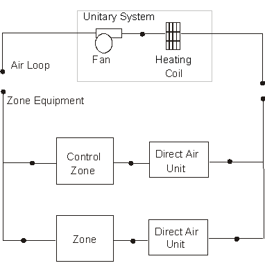
Figure 104. Schematic of Blow Through Heat-Only Unitary System
Links to the fan and heating coil specifications are provided in the unitary system input data syntax. In addition, the control zone name and the unitary system design operating conditions are specified by the unitary system syntax.
This alpha field contains the identifying name for the unitary system.
This alpha field contains the schedule name which contains information on the availability of the unitary system to operate.
This alpha field contains the unitary system inlet node name.
This alpha field contains the unitary system outlet node name.
Field: Supply Air Fan Operating Mode Schedule Name
This alpha field specifies the name of the supply air fan operating mode schedule. The supply air fan operating mode may vary during the simulation based on time-of-day or with a change of season. Schedule values of 0 denote that the furnace supply air fan and the heating coil cycle on and off together to meet the heating load (a.k.a. AUTO fan). Schedule values other than 0 denote that the supply fan runs continuously while the heating coil cycles to meet the load.
This numeric field contains the design air outlet temperature in degrees C when the unitary system is heating. If this input field is left blank, the default value is 80 C.
This numeric field contains the design volumetric flow rate of the unitary system in cubic meters per second. This volumetric flow rate should match the flow rate specified for the unitary system fan.
This alpha field contains the identifying zone name where the thermostat controlling the unitary system is located.
This alpha field contains the identifying type of supply air fan specified for the unitary system. Fan type must be Fan:OnOff or Fan:ConstantVolume. Fan:ConstantVolume is used when the Supply Air Fan Operating Mode Schedule values are never 0 and the fan operates continuously. Fan:OnOff is used when the fan cycles on and off with the cooling or heating coil (i.e. Supply Air Fan Operating Mode Schedule values are at times 0).
This alpha field contains the identifying name given to the unitary system fan.
This alpha field has two choices: BlowThrough or DrawThrough. The first choice stands for “blow through fan”. This means that the unit consists of a fan followed by the heating coil. The fan “blows through” the heating coil. The second choice stands for “draw through fan”. This means that the unit consists of the heating coil followed by a fan. The fan “draws air through” the heating coil. If this field is left blank, the default is blow through.
This alpha field contains the identifying type of heating coil specified in the unitary system. Heating coil type must be
Coil:Heating:Electric
Coil:Heating:Gas
This alpha field contains the identifying name given to the unitary system heating coil.
As shown in the example below, correct specification of the heat-only unitary system requires specification of the following objects in addition to the unitary system object:
1) fan (Fan:OnOff or Fan:ConstantVolume)
2) heating coil (Coil:Heating:Gas or Coil:Heating:Electric)
3) direct air unit (AirTerminal:SingleDuct:Uncontrolled) for each zone served by the furnace
Note: the unitary system’s fan and heating coil must be connected in the air loop according to the configuration shown above (Figure 104) when a blow through fan configuration is specified. If a draw through fan is used, the fan is located down stream of the heating coil. In addition, the volumetric air flow rate specified in the direct air unit for the controlling zone should properly reflect the fractional volumetric air flow rate specified in the unitary system object.
AirLoopHVAC:UnitaryHeatOnly,
Gas Unitary System 1, !- Name
FanAndCoilAvailSched, !- Availability Schedule Name
Air Loop Inlet Node, !- Unitary System Air Inlet Node Name
Air Loop Outlet Node, !- Unitary System Air Outlet Node Name
CycFanSchedule, !- Supply Air Fan Operating Mode Schedule Name
80, !- Maximum Supply Air Temperature {C}
1.3, !- Supply Air Flow Rate {m3/s}
East Zone, !- Controlling Zone or Thermostat Location
Fan:OnOff, !- Supply Fan Object Type
Supply Fan 1, !- Supply Fan Name
BlowThrough, !- Fan Placement
Coil:Heating:Gas, !- Heating Coil Object Type
Unitary System Heating Coil; !- Heating Coil Name
Coil:Heating:Gas,
Unitary System Heating Coil, !- Coil Name
FanAndCoilAvailSched, !- Available Schedule Name
0.8, !- Gas Burner Efficiency of the Coil
20000, !- Nominal Capacity of the Coil {W}
Heating Coil Air Inlet Node, !- Coil_Air_Inlet_Node
Air Loop Outlet Node, !- Coil_Air_Outlet_Node
, !- Coil_Temp_Setpoint_Node
100, !- Parasitic Electric Load {W}
PLFCurveforUnitarySystem, !- Part load fraction correlation (function of part load ratio)
10; !- Parasitic Gas Load {W}
Curve:Cubic,
PLFCurveforUnitarySystem, !- Name
0.8, !- Coefficient1 Constant
0.2, !- Coefficient2 x
0.0, !- Coefficient3 x**2
0.0, !- Coefficient4 x**3
0, !- Minimum Value of x
1; !- Maximum Value of x
Fan:OnOff,
Supply Fan 1, !- Fan Name
FanAndCoilAvailSched, !- Available Schedule
0.7, !- Fan Total Efficiency
600.0, !- Delta Pressure {Pa}
1.3, !- Max Flow Rate {m3/s}
0.9, !- Motor Efficiency
1.0, !- Motor In Airstream Fraction
Air Loop Inlet Node, !- Fan_Inlet_Node
Heating Coil Air Inlet Node; !- Fan_Outlet_Node
AirTerminal:SingleDuct:Uncontrolled,
Zone1DirectAir, !- Direct Air Name
FanAndCoilAvailSched, !- Schedule name for on/off schedule
Zone 1 Inlet Node, !- Zone Supply Air Node Name
0.47; !- Maximum air flow rate {m3/s}
AirTerminal:SingleDuct:Uncontrolled,
Zone2DirectAir, !- Direct Air Name
FanAndCoilAvailSched, !- Schedule name for on/off schedule
Zone 2 Inlet Node, !- Zone Supply Air Node Name
0.36; !- Maximum air flow rate {m3/s}
AirTerminal:SingleDuct:Uncontrolled,
Zone3DirectAir, !- Direct Air Name
FanAndCoilAvailSched, !- Schedule name for on/off schedule
Zone 3 Inlet Node, !- Zone Supply Air Node Name
0.47; !- Maximum air flow rate {m3/s}
Example of Heat-Only Unitary System Specification
HVAC,Average,Unitary System Fan Part-Load Ratio
This output variable is the ratio of actual air mass flow rate through the unitary system to the unitary system’s design air mass flow rate (i.e., design volumetric flow rate converted to dry air mass flow rate). For continuous fan operation mode, this variable is always 1.0 when the unitary system is available (based on the availability schedule). For cycling fan/cycling coil operation mode, the actual air mass flow rate is calculated based on the ratio of the sensible heating load to the unitary system heating capacity. For the cycling fan mode, the runtime fraction for the unitary system fan may be different from the fan part-load ratio reported here due the part-load performance of the unitary system’s heating coil (delay at start-up to reach steady-state heating output). In general, runtime fractions are reported by individual components where appropriate (e.g., Fan:OnOff).
The unitary water-to-air heat pump is similar to the unitary air-to-air heat pump except water is used on the source side. Links to the fan, WaterToAirHeatPump cooling coil, WaterToAirHeatPump heating coil, and supplementary heating coil specifications are provided in the heat pump’s input data syntax. The heat pump switches between cooling and heating depending on the zone’s demand. The load side (air) of the unitary water-to-air heat pump consists of an On/Off fan component, a WaterToAirHeatPump cooling coil component, a WaterToAirHeatPump heating coil component, and a Gas or Electric supplemental heating coil component. The source side (water) of the heat pump is connected to a condenser loop with a heat exchanger (ground heat exchanger or other type) or a plant loop with a heating source such as a boiler and a cooling source such as a chiller or cooling tower. The diagram below shows the setup and connection of the heat pump for the source side and load side for a ground heat exchanger configuration. Note that on the load side, the WaterToAirHeatPump cooling coil must always be placed before the WaterToAirHeatPump heating coil.
There are two type of WaterToAirHeatPump coil models available:
Coil:Cooling:WaterToAirHeatPump:ParameterEstimation
Coil:Heating:WaterToAirHeatPump:ParameterEstimation
Coil:Cooling:WaterToAirHeatPump:EquationFit
Coil:Heating:WaterToAirHeatPump:EquationFit
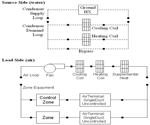
Figure 105. Water to Air Heat Pump Schematic for a BlowThrough Configuration with Ground Heat Exchanger
In addition, the control zone name and the system design operating conditions are specified by the heat pump inputs.
This alpha field contains the identifying name for the unitary system heat pump.
This alpha field contains the schedule name (ref. Schedule) that contains information on the availability of the heat pump to operate. A schedule value greater than 0 (usually 1 is used) indicates that the unit can be on during the hour. A value less than or equal to 0 (usually 0 is used) denotes that the unit must be off for the hour.
This alpha field contains the name of the HVAC system node from which the heat pump draws its inlet air.
This alpha field contains the name of the HVAC system node to which the heat pump sends its outlet air.
This numeric field contains the design volumetric flow rate through the heat pump in cubic meters per second. This volume flow rate is only used when the cooling and heating coil object type is Coil:*:WaterToAirHeatPump:ParameterEstimation. Although a value greater than 0 is required (input cannot be blank or 0), this input is not used for the EquationFit model. Instead, the supply air flow rate is determined by the input in the corresponding Coil:*:WaterToAirHeatPump:EquationFit objects.
This alpha field contains the identifying zone name where the thermostat controlling the heat pump is located.
This alpha field contains the identifying type of supply air fan specified in the heat pump. Fan type must be Fan:OnOff.
This alpha field contains the identifying name given to the heat pump supply air fan, and should match the name specified in the corresponding fan object.
This alpha field contains the identifying type of heating coil specified in the heat pump. Heating coil types are:
Coil:Heating:WaterToAirHeatPump:ParameterEstimation
Coil:Heating:WaterToAirHeatPump:EquationFit
This alpha field contains the identifying name given to the WaterToAirHeatPump heating coil, and should match the name specified in the corresponding WaterToAirHeatPump heating coil object.
This numeric value allows the user to determine how close the air side has to be controlled. Lower the value of convergence better the control of air side conditions and less the zone temperature fluctuations. However in a poorly designed system, a lower convergence might result in warning errors which are caused due to the iteration limit for run time fraction calculation is limited to 20.
This alpha field contains the identifying type of cooling coil specified in the heat pump. Cooling coil types are:
Coil:Cooling:WaterToAirHeatPump:ParameterEstimation
Coil:Cooling:WaterToAirHeatPump:EquationFit
This alpha field contains the identifying name given to the WaterToAirHeatPump cooling coil, and should match the name specified in the corresponding WaterToAirHeatPump cooling coil object.
This numeric value allows the user to determine how close the air side has to be controlled. Lower the value of convergence better the control of air side conditions and less the zone temperature fluctuations. However in a poorly designed system, a lower convergence might result in warning errors which are caused due to the iteration limit for run time fraction calculation is limited to 20.
This numeric field contains the maximum on-off cycling rate for the compressor, which occurs at 50% run time fraction. Suggested values are shown below (Henderson et al. 1999):
This numeric field contains the time constant for the cooling coil's capacity to reach steady state after startup. Suggested values are shown below (Henderson et al. 1999):
This numeric field contains the fraction of on-cycle power use to adjust the part load fraction based on the off-cycle power consumption due to crankcase heaters, controls, fans, and etc. Suggested value values are below (Henderson et al. 1999):
This numeric field contains the time delay for the heat pump supply air fan to shut off after the compressor cycles off in seconds. This value can be obtained from the manufacturer or the heat pump catalog. Enter a value of zero when the heat pump’s fan operating mode is continuous. Suggested value is 60 seconds.
This is the object type of the supplemental heating coil. The only valid choices are:
Coil:Heating:Electric
Coil:Heating:Gas
This alpha field contains the identifying name given to the supplemental heating coil, and should match the name specified in the corresponding supplemental heating coil object.
This numeric field defines the maximum allowed supply air temperature exiting the heat pump supplemental heating coil in degrees Celsius.
This numeric field defines the outdoor air dry-bulb temperature in degrees Celsius above which the heat pump supplemental heating coil is disabled. The temperature for this input field must be less than or equal to 21 C. If this input field is left blank, the default value is 21 C.
This alpha field specifies the name of the outdoor node which controls the operation of the supplemental heating coil. If this field is left blank, the outdoor temperature is based solely on the weather data. If this field is not blank, the node name specified must also be listed in an OutdoorAir:Node object where the height of the node is taken into consideration when calculating outdoor temperature from the weather data. Alternately, the node name must be specified in an OutdoorAir:NodeList object where the outdoor temperature is taken directly from the weather data.
This alpha field has two choices: BlowThrough or DrawThrough. The first choice represents a blow through system where the supply air fan is before the WaterToAirHeatPump cooling/heating coil and the supplementary heating coil. The second choice represents a draw through system where the supply fan is between the WaterToAirHeatPump cooling/heating coil and the supplementary heating coil. If this input field is left blank, the default is blow through.
This alpha field specifies the name of the supply air fan operating mode schedule. The supply air fan operating mode may vary during the simulation based on time-of-day or with a change of season. Schedule values of 0 denote that the supply air fan and the heating/cooling coil cycle on and off together to meet the heating or cooling load (a.k.a. AUTO fan). Schedule values other than 0 denote that the supply air fan runs continuously while the heating or cooling coil cycles to meet the load. If this field is left blank, the model assumes the supply air fan cycles with the heating or cooling coil throughout the simulation period.
As shown in the example below, correct specification of the water-to-air heat pump requires specification of the following objects in addition to the AirLoopHVAC:UnitaryHeatPump:WaterToAir object:
n On/Off fan
n WaterToAirHeatPump cooling coil
n WaterToAirHeatPump heating coil
n Supplementary heating coil
n Direct air unit for each zone served by the heat pump
n Condenser demand branches
It should be noted that the volumetric air flow rate specified in the direct air unit for the controlling zone should properly reflect the fractional volumetric air flow rate specified in the heat pump object.
This alpha input field contains the type of dehumidification control. The following options are valid for this field:
None - meet sensible load only, no active dehumidification control
CoolReheat - cool beyond the dry-bulb temperature set point as required to meet the high humidity setpoint. The excess cooling beyond the cooling set point temperature is offset by the supplemental heating coil.
The default is None. For CoolReheat dehumidification control modes, the maximum humidity setpoint is required. This must be set using a ZoneControl:Humidistat object. When extra dehumidification is required, the system may not be able to meet the humidity setpoint if its full capacity is not adequate. Supplemental heating coil (supplemental heating coil type and name) is a required input in WaterToAir HeatPumps. When dehumidification control is active the heating and the reheat load due to extra dehumidification are met with supplemetal heating coil. The supplemental heating coil capacity must be adequate enough to meet the heating coil load and offset the excess cooling load due to extra dehumidification. The dehumidification control type CoolReheat works only with Coil:Cooling:WaterToAirHeatPump:EquationFit cooling coil type.
AirLoopHVAC:UnitaryHeatPump:WaterToAir,
DXAC Heat Pump 1, !- Name
FanAndCoilAvailSched, !- Availability Schedule Name
Mixed Air Node, !- Air Inlet Node Name
Air Loop Outlet Node, !- Air Outlet Node Name
2, !- Supply Air Flow Fate {m3/s}
East Zone, !- Controlling Zone or Thermostat Location
Fan:OnOff, !- Supply Air Fan Object Type
Supply Fan 1, !- Supply Air Fan Name
Coil:Heating:WaterToAirHeatPump:ParameterEstimation, !- Heating Coil Object Type
Heat Pump Heating Mode, !- Heating Coil Name
0.001, !- Heating Convergence
Coil:Cooling:WaterToAirHeatPump:ParameterEstimation, !- Cooling Coil Object Type
Heat Pump Cooling Mode, !- Cooling Coil Name
0.001, !- Cooling Convergence
2.5, !- Maximum Cycling Rate {cycles/hr}
60, !- Heat Pump Time Constant {s}
0.01, !- Fraction of On-Cycle Power Use
60, !- Heat Pump Fan Delay Time {s}
Coil:Heating:Gas, !- Supplemental Heating Coil Object Type
Heat Pump DX Supp Heating Coil 1, !- Supplemental Heating Coil Name
50, !- Maximum Supply Air Temperature from Supplemental Heater {C}
21, !- Maximum Outdoor Dry-Bulb Temperature for Supplemental Heater Operation {C}
Outside Air Inlet Node, !- Outdoor Dry-Bulb Temperature Sensor Node Name
BlowThrough, !- Fan Placement
CyclingFanSch, !- Supply Air Fan Operating Mode Schedule Name
CoolReheat; !- Dehumidification Control Type
Schedule:Compact,
CyclingFanSch, !- Name
Fraction, !- Schedule Type Limits Name
Through: 12/31, !- Field 1
For: AllDays, !- Field 2
Until: 24:00, !- Field 3
0.0; !- Field 4
Coil:Cooling:WaterToAirHeatPump:ParameterEstimation,
Heat Pump Cooling Mode, !- Name
Scroll, !- Compressor Type
R22, !- Refrigerant Type
0.0015, !- Design Source Side Flow Rate {m3/sec}
38000, !- Nominal Cooling Coil Capacity {W)
0, !- Nominal Time for Condensate Removal to Begin {s}
0, !- Ratio of Initial Moisture Evaporation Rate and Steady State Latent Capacity
3000000, !- High Pressure CutOff {Pa}
0, !- Low Pressure CutOff {Pa}
Water to Air Heat Pump Source Side1 Inlet Node, !- Water Inlet Node Name
Water to Air Heat Pump Source Side1 Outlet Node, !- Water Outlet Node Name
Cooling Coil Air Inlet Node, !- Air Inlet Node Name
Heating Coil Air Inlet Node, !- Air Outlet Node Name
3.78019E+03,!- Parameter 1 {W/K}
2.80303E+03,!- Parameter 2 {W/K}
7.93591E-01,!- Parameter 3 {C}
1.91029E+03,!- Parameter 4 {W}
2.66127E+00,!- Parameter 5
1.06009E-02,!- Parameter 6
1.65103E+00,!- Parameter 7
9.73887E-03,!- Parameter 8
1.04563E+03;!- Parameter 9
Coil:Heating:WaterToAirHeatPump:ParameterEstimation,
Heat Pump HEATING Mode, !- Name
Scroll, !- Compressor Type
R22, !- Refrigerant Type
0.0015, !- Design Source Side Flow Rate {m3/sec}
38000, !- Nominal Heating Coil Capacity {W}
3000000, !- High Pressure CutOff
0, !- Low Pressure CutOff {Pa}
Water to Air Heat Pump Source Side2 Inlet Node, !- Water Inlet Node Name
Water to Air Heat Pump Source Side2 Outlet Node, !- Water Outlet Node Name
Heating Coil Air Inlet Node, !- Air Inlet Node Name
SuppHeating Coil Air Inlet Node, !- Air Outlet Node Name
3.91379E+03, !- Parameter 1 {W/K}
5.94753E-01, !- Parameter 2 {C}
2.49945E+03, !- Parameter 3 {W}
8.68734E-01, !- Parameter 4
7.23595E-03, !- Parameter 5
3.69126E+00, !- Parameter 6
1.75701E-05, !- Parameter 7
3.65348E+03; !- Parameter 8
Coil:Heating:Gas,
Heat Pump DX Supp Heating Coil 1, !- Name
FanAndCoilAvailSched, !- Availability Schedule Name
0.8, !- Gas Burner Efficiency
32000, !- Nominal Capacity {W}
SuppHeating Coil Air Inlet Node, !- Air Inlet Node Name
Air Loop Outlet Node; !- Air Outlet Node Name
BRANCH,
Gshp Cooling Condenser Branch, !- Name
0, !- Maximum Flow Rate {m3/s}
, !- Pressure Drop Curve Name
Coil:Cooling:WaterToAirHeatPump:ParameterEstimation, !- Component 1 Object Type
Heat Pump Cooling Mode, !- Component 1 Name
Water to Air Heat Pump Source Side1 Inlet Node, !- Component 1 Inlet Node Name
Water to Air Heat Pump Source Side1 Outlet Node, !- Component 1 Outlet Node Name
ACTIVE; !- Component 1 Branch Control Type
BRANCH,
Gshp Heating Condenser Branch, !- Name
0, !- Maximum Flow Rate {m3/s}
, !- Pressure Drop Curve Name
Coil:Heating:WaterToAirHeatPump:ParameterEstimation, !- Component 1 Object Type
Heat Pump Heating Mode, !- Component 1 Name
Water to Air Heat Pump Source Side2 Inlet Node, !- Component 1 Inlet Node Name
Water to Air Heat Pump Source Side2 Outlet Node, !- Component 1 Outlet Node Name
ACTIVE; !- Component 1 Branch Control Type
Fan:OnOff,
Supply Fan 1, !- Name
FanAndCoilAvailSched, !- Availability Schedule Name
0.7, !- Fan Efficiency
300.0, !– Pressure Rise {Pa}
2.0, !- Maximum Flow Rate {m3/s}
0.9, !- Motor Efficiency
1.0, !- Motor In Airstream Fraction
Mixed Air Node, !- Air Inlet_Node Name
Cooling Coil Air Inlet Node; !- Air Outlet Node Name
AirTerminal:SingleDuct:Uncontrolled,
Zone1DirectAir, !- Name
FanAndCoilAvailSched, !- Availability Schedule Name
Zone 1 Inlet Node, !- Zone Supply Air Node Name
0.7; !- Maximum Air Flow Rate {m3/s}
AirTerminal:SingleDuct:Uncontrolled,
Zone2DirectAir, !- Name
FanAndCoilAvailSched, !- Availability Schedule Name
Zone 2 Inlet Node, !- Zone Supply Air Node Name
0.6; !- Maximum Air Flow Rate {m3/s}
AirTerminal:SingleDuct:Uncontrolled,
Zone3DirectAir, !- Name
FanAndCoilAvailSched, !- Availability Schedule Name
Zone 3 Inlet Node, !- Zone Supply Air Node Name
0.7; !- Maximum Air Flow Rate {m3/s}
Energy use reporting for the water-to-air heat pump is documented under the heat pump coil object types:
Coil:Cooling:WaterToAirHeatPump:ParameterEstimation
Coil:Heating:WaterToAirHeatPump:ParameterEstimation
Coil:Cooling:WaterToAirHeatPump:EquationFit
Coil:Heating:WaterToAirHeatPump:EquationFit
The heat pump demand as well as the compressor and fan part-load ratios may be obtained with the report variables shown below.
HVAC,Average, Unitary Heat Pump Sensible Cooling Demand[W]
HVAC,Average, Unitary Heat Pump Latent Cooling Demand[W]
HVAC,Average, Unitary Heat Pump Heating Demand[W]
HVAC,Average, Unitary Heat Pump Compressor Part-Load Ratio
HVAC,Average, Unitary Heat Pump Fan Part-Load Ratio
HVAC,Average, Heat Pump Dehumidification Induced Heating Demand Rate [W]
This output variable is the sensible cooling requested from the zone thermostat in watts. This value is calculated using the unitary heat pump outlet air and zone conditions, the specific heat of the zone air, and the supply air mass flow rate entering/leaving the system. This value is calculated for each HVAC system timestep being simulated, and the results are averaged for the timestep being reported.
This output variable is the latent cooling requested from the zone humidistat in watts. This value is calculated using the unitary heat pump outlet air and zone conditions, the heat of vaporization of water at the current zone conditions, and the supply air mass flow rate entering/leaving the system. This value is calculated for each HVAC system timestep being simulated, and the results are averaged for the timestep being reported.
This output variable is the sensible heating requested from the zone thermostat in watts. This value is calculated using the unitary heat pump outlet air and zone conditions, the specific heat of the zone air, and the supply air mass flow rate entering/leaving the system. This value is calculated for each HVAC system timestep being simulated, and the results are averaged for the timestep being reported.
This output variable is the ratio of actual load on the unitary system to the unitary system’s steady state output. This ratio is based on the nominal capacity of the unit.
This output variable is the ratio of actual air mass flow rate through the unitary system to the unitary system’s design air mass flow rate (i.e., design volumetric flow rate converted to dry air mass flow rate). For continuous fan operation mode, this variable is always 1.0 when the unitary system is available (based on the availability schedule).
This output variable is the additional heating demand rate of the supplemental heating coil of a Water-to-Air heat pumps in Watts. This additional heating demand is induced when zone air overshoots the heating setpoint due to extra dehumidification requirement to meet the high humidity setpoint. This value is always positive. This value is calculated for each HVAC system timestep, and the results are averaged for the timestep being reported.
The changeover-bypass variable air volume (CBVAV) unitary system is a compound object made up of other components. Each CBVAV system consists of an outdoor air mixer, direct expansion (DX) cooling coil, heating coil, and a supply air fan as shown in the figures below. Zone thermostats and terminal units are required in each zone served by this system. The terminal units are specific to this system type and are either AirTerminal:SingleDuct:VAV:HeatAndCool:Reheat or AirTerminal:SingleDuct:VAV:HeatAndCool:NoReheat. A zone humidistat and single zone max humidity set point manager may also be specified to help control high humidity levels. These individual components are described elsewhere in this document. The CBVAV unitary system object coordinates the operation of these components and is modeled as a type of air loop equipment (Ref. AirLoopHVAC).
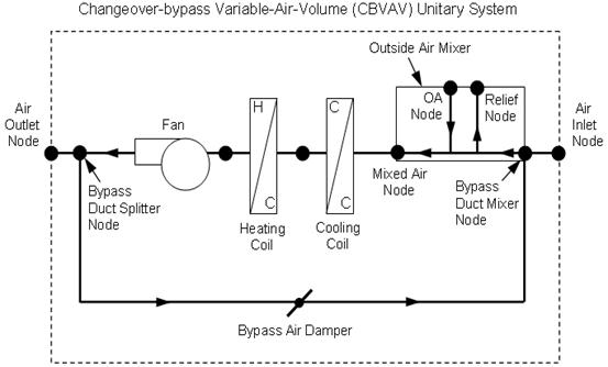
Figure 106. Schematic of a CBVAV unitary system (draw through fan placement)
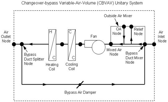
Figure 107. Schematic of a CBVAV unitary system (blow through fan placement)
Links to the CBVAV system’s supply air fan, coils, and outdoor air mixer specifications are provided in the object’s input syntax. Additional inputs include system and outdoor air flow rates during heating and cooling operation, the priority control mode, and dehumidification control type. A description of each input field for the CBVAV unitary system compound object is provided below.
This alpha field defines a unique user-assigned name for an instance of a changeover-bypass VAV system. Any reference to this system by another object will use this name.
This alpha field defines the name of the schedule (ref: Schedule) that denotes whether the system operates during a given time period. A schedule value equal to 0 denotes that the system must be off for that time period, and a schedule value greater than 0 denotes that the system is available to operate during that time period. This schedule may be used to completely disable the system (all of its coils and the supply air fan) as required.
This numeric field defines the air flow rate through the system (i.e., through the fan and heating/cooling coils) in cubic meters per second when the DX cooling coil is operating. Values must be greater than 0, or this field is autosizable.
This numeric field defines the air flow rate through the system (i.e., through the fan and heating/cooling coils) in cubic meters per second when the heating coil is operating. Values must be greater than 0, or this field is autosizable.
This numeric field defines the air flow rate through the system (i.e., through the fan and heating/cooling coils) in cubic meters per second when neither cooling nor heating is required (i.e., the DX cooling coil and heating coil are off but the supply air fan operates). Values must be greater than or equal to zero, or this field is autosizable. This field is only used when the unitary system’s supply air fan operating mode is specified as continuous fan operation (Ref. Field: Supply air fan operating mode schedule name). If the system’s supply air fan operating mode is specified as continuous fan operation and this value is set to zero or the field is left blank, then the model assumes that the system air flow rate when no heating/cooling is needed is equal to the system air flow rate when the coils were last operating (for cooling operation or heating operation).
This numeric field defines the outdoor air flow rate through the system (i.e., through the Outdoor air Mixer’s Outside_Air_Stream_Node) in cubic meters per second when the DX cooling coil is operating. Values must be greater than or equal to 0, or this field is autosizable. Note that the outdoor air flow rate during cooling operating can be changed during the simulation using a multiplier schedule (Ref. Field: Outdoor air volumetric flow rate multiplier schedule name). For any simulation timestep, the outdoor air flow rate during cooling operation cannot exceed the system air volumetric flow rate during cooling operation.
This numeric field defines the outdoor air flow rate through the system (i.e., through the Outdoor air Mixer’s Outside_Air_Stream_Node) in cubic meters per second when the heating coil is operating. Values must be greater than or equal to 0, or this field is autosizable. Note that the outdoor air flow rate during heating operating can be changed during the simulation using a multiplier schedule (Ref. Field: Outdoor air volumetric flow rate multiplier schedule name). For any simulation timestep, the outdoor air flow rate during heating operation cannot exceed the system air volumetric flow rate during heating operation.
This numeric field defines the outdoor air flow rate through the system (i.e., through the Outdoor air Mixer’s Outside_Air_Stream_Node) in cubic meters per second when neither cooling nor heating is required (i.e., the DX cooling coil and heating coil are off but the supply air fan operates). Values must be greater than or equal to 0, or this field is autosizable. Note that the outdoor air flow rate when no cooling/heating is needed can be changed during the simulation using a multiplier schedule (Ref. Field: Outdoor air volumetric flow rate multiplier schedule name). For any simulation timestep, the outdoor air flow rate when no cooling/heating is needed cannot exceed the system air volumetric flow rate when no cooling/heating is needed. This field is only used when the unitary system’s supply air fan operating mode is specified as continuous fan operation (Ref. Field: Supply air fan operating mode schedule name). If the system’s supply air fan operating mode is specified as continuous fan operation and this value is set to zero or the field is left blank, then the model assumes that the outdoor air flow rate when no cooling/heating is needed is equal to the outdoor air flow rate when the coils were last operating (for cooling operation [i.e. Outdoor air volumetric flow rate during cooling operation] or heating operation [i.e. Outdoor air volumetric flow rate during heating operation]) and this field is not used.
This alpha field defines the name of a schedule (ref: Schedule) that contains multipliers for the outdoor air volume flow rates (heating, cooling, no heating/cooling). Schedule values must be from zero to 1. If this field is left blank, then the model assumes that the outdoor air multiplier is 1 for the entire simulation period.
This alpha field defines the name of the HVAC system node from which the system draws its inlet air.
This alpha field defines the name of the HVAC system node where the bypass air mixes with the unitary system’s inlet air. This name should match the name of the Return Air Stream Node Name for the OutdoorAir:Mixer associated with this system. This node name must be different from the system’s air inlet node name.
This alpha field defines the name of the HVAC system node where the conditioned air is split into bypass air and supply air leaving the system (e.g., delivered to the terminal units). This splitter air node name should match the outlet node name for the last component (furthest downstream) in this unitary system. For blow through fan placement, the splitter air node is the outlet node of the heating coil. For draw through fan placement, the splitter node is the outlet node of the supply air fan.
This alpha field defines the name of the HVAC system node to which the system sends its outlet air.
This field specifies the type of outdoor air mixer used by this CBVAV unitary system. The outdoor air mixer component is part of the CBVAV unitary compound object. The only available outdoor air mixer type is:
OutdoorAir:Mixer
This alpha field defines the name of an outdoor air mixer component that composes part of the CBVAV system. The name of the outdoor air mixer’s Return_Air_Stream_Node should match the bypass duct mixer node name, and be different from the CBVAV system’s air inlet node name. The Mixed Air Node Name of the outdoor air mixer should be the same as the CBVAV system’s supply fan inlet air node (for blow through fan placement) or the system’s DX cooling coil inlet node (for draw through fan placement).
This alpha field defines the type of fan used by this unitary system. The only valid choices are Fan:OnOff and Fan:ConstantVolume. The input requirements for these fan objects are described elsewhere in this document.
This alpha field defines the name of the fan component that composes part of this unitary system. Note that the fan component’s maximum flow rate should be greater than or equal to the largest system air volumetric flow rate specified for this unitary system (heating, cooling, and no heating/cooling). In addition, the fan’s inlet air node should be the same as the outdoor air mixer’s Mixed Air Node (for blow through fan placement) or the heating coil’s outlet node (for draw through fan placement). The fan outlet air node should be the same as the DX cooling coil’s air inlet node (for blow through fan placement) or the system’s bypass duct splitter node (for draw through fan placement).
This alpha field defines the placement of the supply air fan within this unitary system. The only valid choices are BlowThrough and DrawThrough. With blow through placement, the supply air fan is located immediately upstream of the system’s cooling coil. With draw through placement, the supply air fan is located immediately downstream of the heating coil.
This alpha field defines the name of a schedule that specifies the supply air fan operating mode during the simulation. A schedule value of 0 denotes the fan cycles off when no cooling or heating is required, and any other value denotes that the fan runs continuously regardless of the need for heating or cooling. If this field is left blank, the model assumes continuous supply air fan operation for the entire simulation period.
This alpha field defines the type of cooling coil used by this unitary system. There are three valid choices for this field:
Coil:Cooling:DX:SingleSpeed
CoilSystem:Cooling:DX:HeatExchangerAssisted
Coil:Cooling:DX:TwoStageWithHumidityControlMode
The input requirements for these cooling coil objects are described elsewhere in this document.
This alpha field defines the name of the cooling coil used by this unitary system, and this name should match the name specified in the corresponding cooling coil object.
This alpha field defines the type of heating coil used by this unitary system. The only valid choices are:
Coil:Heating:Electric
Coil:Heating:Gas
Coil:Heating:DX:SingleSpeed
The input requirements for these heating coil objects are described elsewhere in this document.
This alpha field defines the name of the heating coil used by this unitary system, and this name should match the name specified in the corresponding heating coil object.
This choice field defines the cooling or heating priority control mode for the unitary system. Valid choices are:
CoolingPriority
HeatingPriority
ZonePriority
If CoolingPriority is selected, the system operates to meet the cooling load if any zone served by this system (air loop) requires cooling. If no zones require cooling, then the system operates in heating mode if needed. If HeatingPriority is selected, the system operates to meet the heating load if any zone requires heating. If no zones require heating, then the system operates in cooling mode if needed. If ZonePriority is selected, the system operates based on the maximum number of zones requiring either heating or cooling. If the number of zones requiring cooling is greater than the number of zones requiring heating, then the system operates in cooling mode. If the number of zones requiring heating is greater than the number of zones requiring cooling, then the system operates in heating mode. If the number of zones requiring cooling equals the number of zones requiring heating, then the largest combined load (i.e., the sum of the cooling loads for zones requiring cooling compared to the sum of the heating loads for zones that require heating) sets the cooling or heating operating mode for the system during that simulation timestep.
This numeric field defines the minimum outlet air temperature leaving the system when the unit is operating to provide cooling. Values are specified in degrees Celsius and must be greater than 0. The default value is 8˚C. This value must be less than or equal to the maximum outlet air temperature during heating operation.
This numeric field defines the maximum outlet air temperature leaving the system when the unit is operating to provide heating. Values are specified in degrees Celsius and must be greater than 0. The default value is 50˚C. This value must be greater than or equal to the minimum outlet air temperature during cooing operation.
This alpha field contains the type of dehumidification control. The following options are valid for this field:
None - meet sensible load only, no active dehumidification control
Multimode - activate enhanced dehumidification mode as needed and meet sensible load. This option is used to model DX equipment with a controllable heat exchanger assisting the DX cooling coil for improved dehumidification. It is valid only with cooling coil type = Coil:Cooling:DX:TwoStageWithHumidityControlMode.
CoolReheat - cool beyond the dry-bulb temperature set point as required to meet the high humidity setpoint. It is valid only with cooling coil type = Coil:Cooling:DX:TwoStageWithHumidityControlMode.
The default is None. For the other dehumidification control modes, the maximum humidity setpoint on the CBVAV system’s air outlet node is used. This must be set using a ZoneControl:Humidistat and one of:
n SetpointManager:SingleZone:Humidity:Maximum
n SetpointManager:MultiZone:Humidity:Maximum
n SetpointManager:MultiZone:MaximumHumidity:Average
objects. When extra dehumidification is required, the system may not be able to meet the humidity setpoint if its full capacity is not adequate.
As shown in the example below, correct specification of the CBVAV unitary system requires specification of the following objects in addition to the AirLoopHVAC:UnitaryHeatCool:VAVChangeoverBypass object:
1) outdoor air mixer (OutdoorAir:Mixer)
2) fan (Fan:OnOff or Fan:ConstantVolume)
3) cooling coil (Coil:Cooling:DX:SingleSpeed, CoilSystem:Cooling:DX:HeatExchangerAssisted, or Coil:Cooling:DX:TwoStageWithHumidityControlMode)
4) heating coil (Coil:Heating:Gas, Coil:Heating:Electric, or Coil:Heating:DX:SingleSpeed)
5) terminal unit for each zone being served by this system (AirTerminal:SingleDuct:VAV:HeatAndCool:Reheat or AirTerminal:SingleDuct:VAV:HeatAndCool:NoReheat)
Note: The fan, heating coil, cooling coil, and outdoor air mixer must be connected in the air loop according to the configurations shown above (Figure 106 and Figure 107).
AirLoopHVAC:UnitaryHeatCool:VAVChangeoverBypass,
GasHeat CBVAV System, !- Name of unitary system
FanAndCoilAvailSched, !- Availability schedule name
1.8, !- System air volumetric flow rate during cooling operation {m3/s}
1.7, !- System air volumetric flow rate during heating operation {m3/s}
1.6, !- System air volumetric flow rate when no cooling or heating is needed {m3/s}
0.32, !- Outdoor air volumetric flow rate during cooling operation {m3/s}
0.3, !- Outdoor air volumetric flow rate during heating operation {m3/s}
0.27, !- Outdoor air volumetric flow rate when no cooling or heating is needed {m3/s}
Outdoor Air Multiplier Schedule, !- Outdoor air volumetric flow rate multiplier schedule name
Air Loop Inlet Node, !- Air inlet node name
Mixer Inlet Node, !- Bypass duct mixer node name
Heating Coil Air Outlet Node, !- Bypass duct splitter node name
Air Loop Outlet Node, !- Air outlet node name
OutdoorAir:Mixer, !- Outdoor Air Mixer Object Type
Outdoor air Mixer, !- Outdoor air mixer name
Fan:OnOff, !- Supply air fan type
Supply Fan 1, !- Supply air fan name
BlowThrough, !- Supply air fan placement
Fan OpMode Schedule, !- Supply air fan operating mode schedule name
Coil:Cooling:DX:TwoStageWithHumidityControlMode, !- Cooling coil type
ACDXCoil 2, !- Cooling coil name
Coil:Heating:Gas, !- Heating coil type
Furnace Heating Coil 1, !- Heating coil name
CoolingPriority, !- Priority control mode
10.0, !- Minimum outlet air temperature during cooling operation {C}
50.0, !- Maximum outlet air temperature during heating operation {C}
None; !- Dehumidification control type
OutdoorAir:Mixer,
Outdoor air Mixer, !- Name
Mixed Air Node, !- Mixed Air Node Name
Outdoor air Inlet Node, !- Outdoor Air Stream Node
Relief Air Outlet Node, !- Relief Air Stream Node Name
Mixer Inlet Node; !- Return Air Stream Node Name
Fan:OnOff,
Supply Fan 1, !- Fan Name
FanAndCoilAvailSched, !- Available Schedule
0.7, !- Fan Total Efficiency
600.0, !- Delta Pressure {Pa}
1.8, !- Max Flow Rate {m3/s}
0.9, !- Motor Efficiency
1.0, !- Motor In Airstream Fraction
Mixed Air Node, !- Fan_Inlet_Node
DX Cooling Coil Air Inlet Node; !- Fan_Outlet_Node
Coil:Cooling:DX:TwoStageWithHumidityControlMode,
ACDXCoil 2, !- Coil Name
FanAndCoilAvailSched, !- Availability Schedule
DX Cooling Coil Air Inlet Node, !- Coil Air Inlet Node
Heating Coil Air Inlet Node, !- Coil Air Outlet Node
, !- Crankcase Heater Capacity {W}
, !- Maximum Outdoor Dry-bulb Temperature for Crankcase Heater Operation {C}
2, !- Number of Capacity Stages
0, !- Number of Enhanced Dehumidification Modes
CoilPerformance:DX:Cooling, !- Normal Mode Stage 1 Coil Performance Object Type
ACDXCoil 2 Standard Mode-Stage 1, !- Normal Mode Stage 1 Coil Performance Object Name
CoilPerformance:DX:Cooling, !- Normal Mode Stage 1+2 Coil Performance Object Type
ACDXCoil 2 Standard Mode-Stage 1&2; !- Normal Mode Stage 1+2 Coil Performance Object Name
Coil:Heating:Gas,
Furnace Heating Coil 1, !- Coil Name
FanAndCoilAvailSched, !- Available Schedule
0.8, !- Gas Burner Efficiency of the Coil
35000, !- Nominal Capacity of the Coil {W}
Heating Coil Air Inlet Node, !- Coil_Air_Inlet_Node
Heating Coil Air Outlet Node; !- Coil_Air_Outlet_Node
AirTerminal:SingleDuct:VAV:HeatAndCool:Reheat,
Zone 1 VAV System, !- Name of System
FanAndCoilAvailSched, !- System Availability schedule
Zone 1 Reheat Air Inlet Node, !- DAMPER Air Outlet Node
Zone 1 VAV Inlet Node, !- UNIT Air Inlet Node
0.583, !- Maximum air flow rate {m3/s}
0.25, !- Zone Minimum Air Flow Fraction
, !- Control node
Coil:Heating:Electric, !- Reheat Component Object
Reheat Coil Zone 1, !- Name of Reheat Component
0.0, !- Max Reheat Water Flow {m3/s}
0.0, !- Min Reheat Water Flow {m3/s}
Zone 1 Reheat Air Outlet Node, !- UNIT Air Outlet Node
0.001; !- Convergence Tolerance
AirTerminal:SingleDuct:VAV:HeatAndCool:Reheat,
Zone 2 VAV System, !- Name of System
FanAndCoilAvailSched, !- System Availability schedule
Zone 2 Reheat Air Inlet Node, !- DAMPER Air Outlet Node
Zone 2 VAV Inlet Node, !- UNIT Air Inlet Node
0.583, !- Maximum air flow rate {m3/s}
0.25, !- Zone Minimum Air Flow Fraction
, !- Control node
Coil:Heating:Electric, !- Reheat Component Object
Reheat Coil Zone 2, !- Name of Reheat Component
0.0, !- Max Reheat Water Flow {m3/s}
0.0, !- Min Reheat Water Flow {m3/s}
Zone 2 Reheat Air Outlet Node, !- UNIT Air Outlet Node
0.001; !- Convergence Tolerance
AirTerminal:SingleDuct:VAV:HeatAndCool:NoReheat,
Zone 3 VAV System, !- Name of System
FanAndCoilAvailSched, !- System Availability schedule
Zone 3 Reheat Air Outlet Node, !- UNIT Air Outlet Node
Zone 3 VAV Inlet Node, !- UNIT Air Inlet Node
0.584, !- Maximum air flow rate {m3/s}
0.25; !- Zone Minimum Air Flow Fraction
HVAC,Average,Changeover-bypass VAV Total Heating Rate[W]
HVAC,Sum,Changeover-bypass VAV Total Heating Energy[J]
HVAC,Average,Changeover-bypass VAV Total Cooling Rate[W]
HVAC,Sum,Changeover-bypass VAV Total Cooling Energy[J]
HVAC,Average,Changeover-bypass VAV Sensible Heating Rate[W]
HVAC,Sum,Changeover-bypass VAV Sensible Heating Energy[J]
HVAC,Average,Changeover-bypass VAV Sensible Cooling Rate[W]
HVAC,Sum,Changeover-bypass VAV Sensible Cooling Energy[J]
HVAC,Average,Changeover-bypass VAV Latent Heating Rate[W]
HVAC,Sum,Changeover-bypass VAV Latent Heating Energy[J]
HVAC,Average,Changeover-bypass VAV Latent Cooling Rate[W]
HVAC,Sum,Changeover-bypass VAV Latent Cooling Energy[J]
HVAC,Average,Changeover-bypass VAV Electric Power[W]
HVAC,Sum,Changeover-bypass VAV Electric Consumption[J]
HVAC,Average,Changeover-bypass VAV Fan Part-Load Ratio
HVAC,Average,Changeover-bypass VAV Compressor Part-Load Ratio
HVAC,Average,Changeover-bypass VAV Bypass Mass Flow Rate[kg/s]
HVAC,Average,Changeover-bypass VAV Outlet Air Set Point Temp[C]
This output field is the total (enthalpy) heat addition rate of the CBVAV system in Watts. This value is calculated using the enthalpy difference of the outlet air and inlet air streams, and the supply air mass flow rate entering/leaving the system. This value is calculated for each HVAC system timestep being simulated, and the results (enthalpy addition only) are averaged for the timestep being reported.
This output field is the total (enthalpy) heat addition of the CBVAV system in Joules over the timestep being reported. This value is calculated using the enthalpy difference of the outlet air and inlet air streams, the supply air mass flow rate entering/leaving the system, and the HVAC simulation timestep. This value is calculated for each HVAC system timestep being simulated, and the results (enthalpy addition only) are summed for the timestep being reported.
This output field is the total (enthalpy) heat extraction rate of the CBVAV system in Watts. This value is calculated using the enthalpy difference of the outlet air and inlet air streams, and the supply air mass flow rate entering/leaving the system. This value is calculated for each HVAC system timestep being simulated, and the results (enthalpy extraction only) are averaged for the timestep being reported.
This output field is the total (enthalpy) heat extraction of the CBVAV system in Joules over the timestep being reported. This value is calculated using the enthalpy difference of the outlet air and inlet air streams, the supply air mass flow rate entering/leaving the system, and the HVAC simulation timestep. This value is calculated for each HVAC system timestep being simulated, and the results (enthalpy extraction only) are summed for the timestep being reported.
This output field is the sensible heat addition rate of the CBVAV system in Watts. This value is calculated using the enthalpy difference of the outlet air and inlet air streams at a constant humidity ratio, and the supply air mass flow rate entering/leaving the system. This value is calculated for each HVAC system timestep being simulated, and the results (heating only) are averaged for the timestep being reported.
This output field is the sensible heat addition of the CBVAV system in Joules over the timestep being reported. This value is calculated using the enthalpy difference of the outlet air and inlet air streams at a constant humidity ratio, the supply air mass flow rate entering/leaving the system, and the HVAC simulation timestep. This value is calculated for each HVAC system timestep being simulated, and the results (heating only) are summed for the timestep being reported.
This output field reports the moist air sensible heat extraction rate of the CBVAV system in Watts. This value is calculated using the enthalpy difference of the outlet air and inlet air streams at a constant humidity ratio, and the supply air mass flow rate entering/leaving the system. This value is calculated for each HVAC system timestep being simulated, and the results (cooling only) are averaged for the timestep being reported.
This output field reports the moist air sensible heat extraction of the CBVAV system in Joules over the timestep being reported. This value is calculated using the enthalpy difference of the outlet air and inlet air streams at a constant humidity ratio, the supply air mass flow rate entering/leaving the system, and the HVAC simulation timestep. This value is calculated for each HVAC system timestep being simulated, and the results (cooling only) are summed for the timestep being reported.
This output field is the latent heat addition (humidification) rate of the CBVAV system in Watts. This value is calculated as the difference between the total energy rate and the sensible energy rate provided by the system. This value is calculated for each HVAC system timestep being simulated, and the results (latent heat addition only) are averaged for the timestep being reported.
This output field is the latent heat addition (humidification) of the CBVAV system in Joules over the timestep being reported. This value is calculated as the difference between the total energy and the sensible energy delivered by the system. This value is calculated for each HVAC system timestep being simulated, and the results (latent heat addition only) are summed for the timestep being reported.
This output field is the latent heat extraction (dehumidification) rate of the CBVAV system in Watts. This value is calculated as the difference between the total energy rate and the sensible energy rate provided by the system. This value is calculated for each HVAC system timestep being simulated, and the results (latent heat extraction only) are averaged for the timestep being reported.
This output field is the latent heat extraction (dehumidification) of the CBVAV system in Joules over the timestep being reported. This value is calculated as the difference between the total energy and the sensible energy delivered by the system. This value is calculated for each HVAC system timestep being simulated, and the results (latent heat extraction only) are summed for the timestep being reported.
This output field is the electricity consumption rate of the CBVAV system in Watts. The consumption includes electricity used by the DX compressor (including crankcase heater), fans (indoor supply air fan and the condenser fans associated with the DX coil[s]), and the heating coil (if electric). This value is calculated for each HVAC system timestep being simulated, and the results are averaged for the timestep being reported.
This output field is the electricity consumption of the CBVAV system in Joules for the time period being reported. The consumption includes electricity used by the DX compressor (including crankcase heater), fans (indoor supply air fan and the condenser fans associated with the DX coil[s]), and the heating coil (if electric). This value is calculated for each HVAC system timestep being simulated, and the results are summed for the timestep being reported.
This output field is the part-load ratio of the supply air fan, which will be either zero or 1 for each simulation timestep. For this system, the fan will operate continuously for the simulation timestep if the system is available (ref. Field: Availability schedule name) and there is a cooling or heating load to be met (i.e., fan part-load ratio will equal 1). When the system is available but there is no cooling or heating load to be met, the fan will either be off for the entire timestep or on for the entire timestep depending on the supply air fan operating mode schedule (ref. Field: Supply air fan operating mode schedule name). This value is set for each HVAC system timestep being simulated, and the results are averaged for the timestep being reported.
This output field is the part-load ratio of the compressor used by the DX coils (cooling and heating). The compressor part-load ratio is defined as the total coil load divided by the coil steady-state capacity (steady-state capacity of first stage for multi-mode coils). This value is calculated for each HVAC system timestep being simulated, and the results are averaged for the timestep being reported.
This output field is the mass flow rate of air, in kg/s, being bypassed from the supply air path and blended with the air entering the CBVAV system. This value is calculated for each HVAC system timestep being simulated, and the results are averaged for the timestep being reported.
This output field is the dry-bulb set point temperature in degrees Celsius. This set point temperature is calculated by the model based on the zone cooling/heating loads calculated by EnergyPlus, and the priority control mode and the dehumidification control type specified for this unitary system. The CBVAV system attempts to achieve the outlet air set point temperature to the extent possible.
The AirLoopHVAC:UnitaryCoolOnly object is a “virtual” component that consists of a DX cooling coil component and its associated controls, as shown in the Figure below. This control object supports several different types of DX cooling coils (see field Cooling Coil Object Type).
This component may be used as a cooling coil in constant volume or variable volume systems, as blow through or draw through, with or without humidity controls. Unlike the other AirLoopHVAC:Unitary system types, this component controls only the DX coil, not the supply fan. AirLoopHVAC:UnitaryCoolOnly is added to a system by placing it in an air loop branch (see Branch object) or in an AirLoopHVAC:OutdoorAirSystem:EquipmentList. It requires one or more setpoint manager (see SetpointManager:*) objects to specify temperature and/or humidity setpoints. A constant volume or variable volume fan is modeled separately from this cooling system. These are the only fan types allowed for this system type (ref. Fan:ConstantVolume and Fan:VariableVolume).
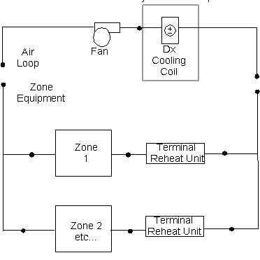
Figure 108. Schematic of AirLoopHVAC:UnitaryCoolOnly Object in an Air Loop for a Blow Through Application
This alpha field contains the identifying name for this component.
This alpha field contains the schedule name that contains information on the availability of the DX coil to operate.
This alpha field contains the identifying name given to the DX cooling coil inlet node, as specified in the DX cooling coil object.
This alpha field contains the identifying name given to the DX cooling coil outlet node, as specified in the cooling coil object.
This alpha field contains the identifying name given to the DX cooling coil control node, this is the node at which the temperature set point is specified by the set point manager.
This alpha field specifies the type of DX cooling coil. The valid choices for this field are:
Coil:Cooling:DX:SingleSpeed
CoilSystem:Cooling:DX:HeatExchangerAssisted
Coil:Cooling:DX:TwoSpeed
Coil:Cooling:DX:TwoStageWithHumidityControlMode
This alpha field contains the identifying name of the DX cooling coil.
As shown in the example below, correct specification of this system requires specification of the DX Cooling Coil object in addition to the AirLoopHVAC:UnitaryCoolOnly object.
This alpha field contains the type of dehumidification control. The following options are valid for this field:
None - meet sensible load only, no active dehumidification control
MultiMode - activate enhanced dehumidification mode as needed and operate to meet the sensible load. If a sensible load exists, the system will operate to meet that sensible load and may not meet the latent load. If no sensible load exists, and Run on Latent Load = Yes, the system will operate to meet the entire latent load. This option is used to model DX equipment with a switchable option such as subcool reheat. It is valid only with Cooling coil type= Coil:Cooling:DX:TwoStageWithHumidityControlMode or CoilSystem:Cooling:DX:HeatExchangerAssisted. If the Run on Latent Load option below is set to Yes, this option may require the use of a heating coil and heating coil outlet air temperature set point manager downstream of this cooling coil to maintain the temperature set point.
CoolReheat - cool beyond the dry-bulb setpoint as required to meet the humidity setpoint. It is valid only with Cooling coil type=Coil:Cooling:DX:TwoStageWithHumidityControlMode. This option requires the use of a heating coil and heating coil outlet air temperature set point manager downstream of this cooling coil to maintain the temperature set point.
The default is None. For all dehumidification controls, the max humidity setpoint on the control node is used. This must be set using a ZoneControl:Humidistat ZoneControl:Humidistat and one of:
n SetpointManager:SingleZone:Humidity:Maximum
n SetpointManager:MultiZone:Humidity:Maximum
n SetpointManager:MultiZone:MaximumHumidity:Average
objects and SetpointManager:OutdoorAirPretreat (optional) objects. When extra dehumidification is required, the equipment may not be able to meet the humidity setpoint if its full capacity is not adequate.
This alpha field specifies if the unit will operate to meet a sensible load as determined by the inlet node dry-bulb temperature and the dry-bulb temperature setpoint on the control node. There are two valid choices, Yes or No. If Yes, unit will run if there is a sensible load. If No, unit will not run if there is only a sensible load. The default is Yes.
This alpha field specifies if the unit will operate to meet a latent load as determined by the inlet node humidity ratio and the max humidity setpoint on the control node. There are two valid choices, Yes or No. If Yes, unit will run if there is a latent load. If both a sensible and latent load exist, the system will operate to maintain the temperature set point. When only a latent load exists, the system will operate to meet the humidity ratio set point and requires the use of a heating coil and heating coil outlet air temperature set point manager downstream of this cooling coil to maintain the temperature set point. If No, unit will not run if there is only a latent load. The default is No.
An example IDF specification:
AirLoopHVAC:UnitaryCoolOnly,
DX Cooling Coil System 1,!- Name
CoolingCoilAvailSched, !- Availability Schedule Name
Cooling Coil Air Inlet Node, !- DX Cooling Coil System Inlet Node Name
Air Loop Outlet Node, !- DX Cooling Coil System Outlet Node Name
Air Loop Outlet Node, !- DX Cooling Coil System Sensor Node Name
Coil:Cooling:DX:SingleSpeed, !- Cooling Coil Object Type
ACDXCoil 1, !- Cooling Coil Name
None, !- Dehumidification Control Type
Yes, !- Run on Sensible Load
No; !- Run on Latent Load
Coil:Cooling:DX:SingleSpeed,
ACDXCoil 1, !- Name
CoolingCoilAvailSched, !- Availability Schedule Name
25000, !- Rated Total Cooling Capacity {W}
0.75, !- Rated Sensible Heat Ratio
3.0, !- Rated COP
1.3, !- Rated Air Flow Rate {m3/s}
Cooling Coil Air Inlet Node, !- Air Inlet Node Name
Air Loop Outlet Node, !- Air Outlet Node Name
WindACCoolCapFT, !- Total Cooling Capacity Function of Temperature Curve Name
WindACCoolCapFFF, !- Total Cooling Capacity Function of Flow Fraction Curve Name
WindACEIRFT, !- Energy Input Ratio Function of Temperature Curve Name
WindACEIRFFF, !- Energy Input Ratio Function of Flow Fraction Curve Name
WindACPLFFPLR; !- Part Load Fraction Correlation Curve Name
Coil Type= Coil:Cooling:DX:TwoStageWithHumidityControlMode
HVAC,Average,DXSystem Cycling Part-Load Ratio
HVAC,Average,DXSystem Compressor Speed Ratio
Coil types=Coil:Cooling:DX:SingleSpeed & CoilSystem:Cooling:DX:HeatExchangerAssisted
HVAC,Average,DXSystem Part-Load Ratio
The system may operate for the entire system timestep, but to meet the load the compressor can cycle on and off. This reports the fraction of the system timestep that the compressor is operating. (1.0 is continuous, 0.0 is off).
This is the ratio of time in a system timestep that the compressor is at rated speed. The compressor speed ratio reports (1.0 is max, 0.0 is min) and any value in between as it is averaged over the timestep.
The DX system can operate with a cycling compressor or a varying speed compressor, This variable reports the fraction of the Full Load that is met during the system timestep. This can differ from the cycling part load ratio or the compressor speed ratio. (1.0 is Full Load and 0.0 is no load)
This model simulates a variable-refrigerant-flow (or variable-refrigerant-volume) air-conditioning system. This system type models direct-expansion cooling and/or heating coils configured in a zone terminal unit. For this system type, the zone terminal units are “connected” to a zone via the zone inlet and exhaust nodes. The zone terminal units are identified in a ZoneTerminalUnitList object. And finally, the name of the ZoneTerminalUnitList object is entered as an input to the AirConditioner:VariableRefrigerantFlow object. The Energyplus connection methodology is shown as dashed and greyed arrows in the figure below according to the following rules:
1. The zone inlet and zone exhaust node names are defined in a ZoneHVAC:EquipmentConnections object (bottom of figure).
2. A ZoneHVAC:TerminalUnit:VariableRefrigerantFlow object will identify these zone exhaust and zone inlet node names as the terminal unit’s air inlet and air outlet nodes, respectively.
3. All zone terminal units that are connected to the same AirConditioner: VariableRefrigerantFlow object are listed in a ZoneTerminalUnitList object.
4. The name of the ZoneTerminalUnitList object is an input to the AirConditioner: VariableRefrigerantFlow object.
5. The AirCondtiioner:VariableRefrigerantFlow object is not listed in an AirloopHVAC object and, therefore, can only be simulated if the terminal units are connected to the AirCondtiioner:VariableRefrigerantFlow object using the ZoneTerminalUnitList.
6. Secondary ZoneHVAC equipment objects may be used in the same zones as the terminal units for other purposes (e.g., code compliance)
The following schematic demonstrates these connection rules.
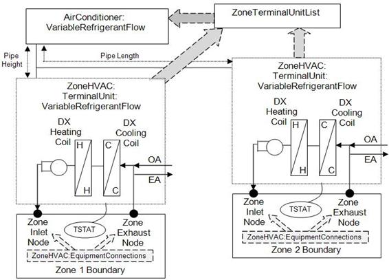
Figure 109. Variable Refrigerant Flow Schematic
Energyplus object type and object name, and node name relationships are also shown in the following figure to aid in the assembly of this HVAC system type.
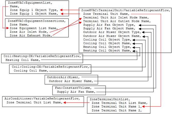
Figure 110. Variable Refrigerant Flow Object Links
This alpha field defines a unique user-assigned name for an instance of a variable refrigerant flow heat pump. Any reference to this heat pump will use this name. Since this object is not listed in an AirloopHVAC object, the most likely use of this name would be for reporting purposes.
This alpha field defines the name of the schedule (ref: Schedule) that denotes whether the heat pump operates during a given time period. A schedule value equal to 0 denotes that the heat pump must be off for that time period. A value other than 0 denotes that the heat pump is available to operate during that time period. This schedule may be used to completely disable the heat pump (and all of its terminal units) as required. If this field is blank, the unit is enabled the entire simulation.
This numeric field defines the total cooling capacity (sensible + latent) of the heat pump at rated conditions in watts. The cooling capacity must be greater than 0 or set to autosize.
This numeric field defines the cooling coefficient of performance at rated conditions. The cooling coefficient of performance includes compressor power and condenser fan power. This COP value does not include impacts due to the supply air fan. The nominal heat pump cooling COP must be greater than 0. If this field is left blank, a default coefficient of performance of 3.3 is assumed.
This numeric field defines the minimum outdoor dry-bulb temperature allowed for cooling operation. Below this temperature, cooling is disabled. If this field is left blank, the default value is -6ºC.
This numeric field defines the maximum outdoor dry-bulb temperature allowed for cooling operation. Above this temperature, cooling is disabled. If this field is left blank, the default value is 43ºC.
This alpha field defines the cooling capacity ratio modifier at low outdoor dry-bulb temperatures. This curve is a bi-quadratic equation using weighted average indoor wet-bulb temperature (i.e., the indoor terminal units weighted average inlet temperatures) and condenser entering air dry-bulb temperature as the independent variables. This performance curve can be used to describe the cooling capacity ratio at low outdoor temperatures (i.e., the following two curves are used) or can be used to describe the performance for all outdoor temperatures (i.e., the following two curves are not used). For this system type it is likely that all three of these performance curves will be required. See the Engineering Reference for more discussion on using this input field.
This alpha field defines the cooling capacity ratio boundary curve name. This curve is a linear, quadratic or cubic curve that defines a change in cooling capacity at a specific condenser entering air dry-bulb temperature as a function of indoor air wet-bulb temperature. This curve is used when the trend in cooling capacity changes dramatically as outdoor temperature changes. If the cooling capacity does not change dramatically with changes in outdoor conditions, this field may be left blank. See the Engineering Reference for more discussion on using this input field.
This alpha field defines the cooling capacity ratio modifier at high outdoor temperatures. This curve is a bi-quadratic equation using weighted average indoor wet-bulb temperature and condenser entering air dry-bulb temperature as the independent variables. This curve is used when the trend in cooling capacity changes dramatically as outdoor temperature changes. If the cooling capacity does not change dramatically with changes in outdoor conditions, this field may be left blank. See the Engineering Reference for more discussion on using this input field.
This alpha field defines the cooling energy input ratio modifier at low outdoor temperatures. This curve is a bi-quadratic equation with a weighted average indoor wet-bulb temperature and condenser entering air dry-bulb temperature as the independent variables. This performance curve can be used to describe the cooling energy input ratio at low outdoor temperatures (i.e., the following two curves are used) or can be used to describe the performance for all outdoor temperatures (i.e., the following two curves are not used). For this system type it is likely that all three of these performance curves will be required. See the Engineering Reference for more discussion on using this input field.
This alpha field defines the cooling energy input ratio boundary curve name. This curve is a linear, quadratic or cubic curve that defines a change in cooling energy at a specific condenser entering air dry-bulb temperature as a function of indoor air wet-bulb temperature. This curve is used when the trend in cooling energy changes dramatically as outdoor temperature changes. If the cooling energy does not change dramatically with changes in outdoor conditions, this field may be left blank. See the Engineering Reference for more discussion on using this input field.
This alpha field defines the cooling energy input ratio modifier at high outdoor temperatures. This curve is a bi-quadratic equation with weighted average indoor wet-bulb temperature and condenser entering air dry-bulb temperature as the independent variables. This curve is used when the trend in cooling energy changes dramatically as outdoor temperature changes. If the cooling energy does not change dramatically with changes in outdoor conditions, this field may be left blank. See the Engineering Reference for more discussion on using this input field.
This alpha field defines the cooling energy input ratio modifier (function of part-load ratio when PLR is less than or equal to 1) curve name. This curve is a linear, quadratic or cubic equation with cooling part-load ratio used as the independent variable. The cooling energy input ratio modifier curve is normalized to 1 at a part-load ratio of 1 and is used only when the operating part-load ratio is less than or equal to 1.
This alpha field defines the cooling energy input ratio modifier (function of part-load ratio when PLR is greater than 1) curve name. This curve is a linear, quadratic or cubic equation with cooling part-load ratio used as the independent variable. The cooling energy input ratio modifier curve is normalized to 1 at a part-load ratio of 1 and is used only when the operating part-load ratio is greater than 1.
This alpha field defines the cooling combination ratio (CR) correction factor curve name for combination ratios greater than or equal to 1. The combination ratio is defined as the total rated indoor terminal unit cooling capacity divided by this heat pump’s rated total cooling capacity. The curve is a linear, quadratic or cubic equation and uses the minimum value of x in the curve object to determine the maximum part-load ratio which is linearly proportional to capacity (i.e., the minimum value of x [CR] in the curve object must be ≥1). The output of this curve provides a multiplier (>1) which is applied to this heat pump’s Rated Total Cooling Capacity. Between a combination ratio of 1 and the curve’s minimum value of x, the multiplier is linearly interpolated. For combination ratio’s less than 1 (i.e., the total indoor terminal unit capacity is less than this heat pump’s rated total capacity), capacity is directly proportional to part-load ratio and this curve will not be used.
This alpha field defines the cooling part-load fraction correlation curve name. This curve is used to define the cycling losses when the condenser’s compressors cycle on and off. The compressor cycles when the cooling part-load ratio is less than the Minimum Heat Pump Part-Load Ratio specified later in this object’s inputs.
This numeric field defines the total heat pump heating capacity at rated conditions in watts. The nominal heat pump heating capacity must be greater than 0 or set to autosize.
This numeric field defines the heating coefficient of performance at rated conditions. The heating coefficient of performance includes compressor power and condenser fan power. This COP value does not include impacts due to the supply air fan. The nominal heat pump heating COP must be greater than 0. If this field is left blank, a coefficient of performance of 3.4 is assumed.
This numeric field defines the minimum outdoor temperature allowed for heating operation. Below this temperature, heating is disabled. If this field is left blank, the default value is -20ºC.
This numeric field defines the maximum outdoor temperature allowed for heating operation. Above this temperature, heating is disabled. If this field is left blank, the default value is 16ºC.
This alpha field defines the heating capacity ratio modifier at low temperature curve name. This curve is a bi-quadratic equation with a weighted average indoor dry-bulb temperature (i.e., the indoor terminal units weighted average inlet temperatures) and condenser entering air dry-bulb or wet-bulb temperature as the independent variables. Since manfacuturers may provide performance data using either outdoor dry-bulb or wet-bulb temperatuers, either of these temperature types may be used for heating performance curves as specified in the Heating Performance Cuvre Outdoor Temperaure Type input field below. This performance curve can be used to describe the heating capacity ratio at low outdoor temperatures (i.e., the following two curves are used) or can be used to describe the performance for all outdoor temperatures (i.e., the following two curves are not used). For this system type it is likely that all three of these performance curves will be required. See the Engineering Reference for more discussion on using this input field.
This alpha field defines the heating capacity ratio boundary curve name. This curve is a quadratic or cubic curve that defines a change in heating capacity at a specific condenser entering air dry-bulb or wet-bulb temperature as a function of indoor air dry-bulb temperature. Since manfacuturers may provide performance data using either outdoor dry-bulb or wet-bulb temperatuers, either of these temperature types may be used for heating performance curves as specified in the Heating Performance Cuvre Outdoor Temperaure Type input field below. This curve is used when the trend in heating capacity changes dramatically as outdoor temperature changes. If the heating capacity does not change dramatically with changes in outdoor conditions, this field may be left blank.
This alpha field defines the heating capacity ratio modifier at high temperature curve name. This curve is a bi-quadratic equation with a weighted average indoor dry-bulb temperature and condenser entering air dry-bulb or wet-bulb temperature as the independent variables. Since manfacuturers may provide performance data using either outdoor dry-bulb or wet-bulb temperatuers, either of these temperature types may be used for heating performance curves as specified in the Heating Performance Cuvre Outdoor Temperaure Type input field below. This curve is used when the trend in heating capacity changes dramatically as outdoor temperature changes. If the heating capacity does not change dramatically with changes in outdoor conditions, this field may be left blank.
This alpha field defines the heating energy input ratio modifier at low temperature curve name. This curve is a bi-quadratic equation with a weighted average indoor dry-bulb temperature and condenser entering air dry-bulb or wet-bulb temperature as the independent variables. Since manfacuturers may provide performance data using either outdoor dry-bulb or wet-bulb temperatuers, either of these temperature types may be used for heating performance curves as specified in the Heating Performance Cuvre Outdoor Temperaure Type input field below. This performance curve can be used to describe the heating energy input ratio at low outdoor temperatures (i.e., the following two curves are used) or can be used to describe the performance for all outdoor temperatures (i.e., the following two curves are not used).
This alpha field defines the heating energy input ratio boundary curve name. This curve is a quadratic or cubic curve that defines a change in heating energy at a specific condenser entering air dry-bulb or wet-bulb temperature as a function of indoor air dry-bulb temperature. Since manfacuturers may provide performance data using either outdoor dry-bulb or wet-bulb temperatuers, either of these temperature types may be used for heating performance curves as specified in the Heating Performance Cuvre Outdoor Temperaure Type input field below. This curve is used when the trend in heating energy changes dramatically as outdoor temperature changes. If the heating energy does not change dramatically with changes in outdoor conditions, this field may be left blank.
This alpha field defines the heating energy input ratio modifier at high temperature curve name. This curve is a bi-quadratic equation with a weighted average indoor dry-bulb temperature and condenser entering air dry-bulb or wet-bulb temperature as the independent variables. Since manfacuturers may provide performance data using either outdoor dry-bulb or wet-bulb temperatuers, either of these temperature types may be used for heating performance curves as specified in the Heating Performance Cuvre Outdoor Temperaure Type input field below. This curve is used when the trend in heating energy changes dramatically as outdoor temperature changes. If the heating energy does not change dramatically with changes in outdoor conditions, this field may be left blank.
This choice field defines the outdoor temperature type used for all performance curves. The valid choices are DryBulbTemperature and WetBulbTemperature. The default value is WetBulbTemperature. Manufacturers will typically provide heating performance data as a function of outdoor air wet-bulb temperatures. This means that the performance (e.g., capacity and energy input ratio) curves will use outdoor wet-bulb temperature as one of the independent variables. At times, manufacturers will only provide performance data as a function of outdoor dry-bulb temperatures. In this case, all performance curves shall be developed using outdoor dry-bulb temperature and this field shall be selected as DryBulbTemperature.
This alpha field defines the heating energy input ratio modifier (function of part-load ratio when PLR is less than or equal to 1) curve name. This curve is a linear, quadratic, or cubic equation with heating part-load ratio used as the independent variable. The heating energy input ratio modifier curve is normalized to 1 at a part-load ratio of 1 and is used only when the part-load ratio is less than or equal to 1.
This alpha field defines the heating energy input ratio modifier (function of part-load ratio when PLR is greater than 1) curve name. This curve is a linear, quadratic, or cubic equation with heating part-load ratio used as the independent variable. The heating energy input ratio modifier curve is normalized to 1 at a part-load ratio of 1 and is used only when the part-load ratio is greater than 1.
This alpha field defines the heating combination ratio (CR) correction factor curve name for combination ratios greater than or equal to 1. The combination ratio is defined as the total rated indoor heating capacity divided by the rated heat pump heating capacity. The curve is either quadratic or cubic and uses the minimum value of x in the curve object to determine the maximum part-load ratio which is linearly proportional to capacity (i.e., the minimum value of x in the curve object must be ≥1). The output of this curve provides a multiplier (>1) which is applied to the Nominal Heat Pump Heating Capacity. Between a combination ratio of 1 and the curve’s minimum value of x, the multiplier is linearly interpolated. For combination ratio’s less than 1, capacity is directly proportional to part-load ratio and this curve will not be used. If this field is left blank, the Cooling Combination Ratio Correction factor will be used.
This alpha field defines the heating part-load fraction correlation curve name. This curve is used to define the cycling losses when the condenser’s compressors cycle on and off. The compressor cycles when the indoor to outdoor heating capacity ratio is less than the Minimum Heat Pump Part-Load Ratio specified in the following field.
This numeric field specifies the minimum operating part-load ratio (PLR) of the heat pump. When the heat pump operates at a PLR below this value, the heat pump’s compressor will cycle to meet the cooling or heating demand. Above this value, the heat pump’s compressor operates the entire time step to meet the cooling or heating demand. The minimum value for this field is 0. If this field is left blank, the default value is 0.15. When the heat pump compressor cycles, the previous field is used to determine cycling losses.
This alpha field defines the name of the zone where the “master” thermostat is located. When the heat pump is connected to multiple zone terminal units, one terminal unit must be selected as the master thermostat. The remaining thermostats are slaves and can operate only in the same mode as the master thermostat.
This choice field determines the logic used to simulate the “master” thermostat. Valid choices are LoadPriority, ZonePriority, ThermostatOffsetPriority, MasterThermostatPriority, and Scheduled. The default value is MasterThermostatPriority. When LoadPriority is selected, the total zone load is used to choose the operating mode as either cooling or heating. When ZonePriority is selected, the number of zones requiring cooling or heating determines the operating mode. When ThermostatOffsetPriority is selected, the zone farthest from the thermostat set point determines the operating mode. The MasterThermostatPriority choice operates the system according the zone load where the master thermostat is located. The heat pump can also be scheduled to operate in either cooling or heating mode. For scheduled operation, a schedule name is entered in the following field.
This alpha field identifies the schedule used when the previous field is set to Scheduled. Schedule values of 0 denote cooling mode while values of 1 denote heating mode. Any other values will force the system off.
This alpha field defines the name of the zone terminal unit list. The name specified here should match the name of a valid ZoneTerminalUnitList object. In addition, each name specified in this list should match the name of a valid ZoneHVAC:TerminalUnit: VariableRefrigerantFlow object. All terminal units connected to this heat pump must be listed in this ZoneTerminalUnitList object.
Note: the previous field is designated at the last field necessary to simulate the variable refrigerant flow heat pump. Tthe following fields do not have to be entered, however, piping loses, defrost operation, crankcase heater operation, and basin heater operation will not be modeled. Defaults for fields not entered may also not apply. These remaing fields must be entered if that portion of the model is to be simulated.
This choice field defines the configuration of the heat pump refrigeration system. This field is reserved for future use. The only valid choice is No.
This numeric field defines the equivalent pipe length in meters between the farthest terminal unit and the heat pump condenser. This value includes the gas refrigerant line length (for both horizontal and vertical distances), fitting losses, pipe bends, and other connections that contribute to piping losses. This field is used to calculate the piping correction factor in cooling mode. This value defines the head losses due to the pipe length between the farthest terminal unit and the heat pump condenser and impacts the maximum available capacity in cooling mode.
This numeric field defines the vertical pipe height in meters between the highest or lowest terminal unit and the heat pump condenser. This value defines the gravitational losses due to a change in height between the highest (positive value), or lowest (negative value) terminal unit and the heat pump condenser. The distance specified here is applied to the piping correction factor calculation for both cooling and heating. If the distance between the highest terminal unit above the heat pump condenser is greater than the distance between the lowest terminal unit below the condenser enter the difference between the highest and lower terminal unit as a positive distance, otherwise enter this difference as a negative distance. Example: if the distance from the heat pump condenser to the highest terminal unit above the condenser is 10 m and the distance from the heat pump condenser to the lowest terminal unit below the condenser is -15 m, then enter a value of -5 m in this field. This head loss impacts the maximum available capacity in cooling mode.
This alpha field defines the linear, quadratic, or cubic curve name used to calculate the piping correction factor for length in cooling mode. Piping losses are a function of piping length. If sufficient piping loss information is available where piping losses are also a function of combination ratio (i.e, in addition to length), a biquadratic performance curve may be used.
This numeric field defines the coefficient used to calculate the piping correction factor for height in cooling mode.
This numeric field defines the equivalent pipe length in meters between the farthest terminal unit and the heat pump condenser. This value includes the liquid refrigerant line length (for both horizontal and vertical distances), fitting losses, pipe bends, and other connections that contribute to piping losses. This field is used to calculate the piping correction factor in heating mode. This value defines the head losses due to the pipe length between the farthest terminal unit and the heat pump condenser and impacts the maximum available capacity in heating mode.
This alpha field defines the linear, quadratic, or cubic curve name used to calculate the piping correction factor for length in heating mode. Piping losses are a function of piping length. If sufficient piping loss information is available where piping losses are also a function of combination ratio (i.e, in addition to length), a biquadratic performance curve may be used.
This numeric field defines the coefficient used to calculate the piping correction factor for height in heating mode.
This numeric field defines the electrical power consumed by the crankcase heater in watts for each compressor. This crankcase heater power is consumed when the outdoor temperature is below the maximum outdoor dry-bulb temperature for crankcase heater operation. The minimum value for this field is 0. If this field is left blank, the default value is 33 watts. Crankcase heater electrical consumption is applied only when the compressor is off or is applied during the off cycle when the compressor is cycling below the Minimum Heat Pump Part-Load Ratio. This field is only used to calculate crankcase heater power and has no impact on heat pump performance.
This numeric field defines the number of compressors in the heat pump condensing unit and is used exclusively to determine the operating characteristics of the crankcase heater. For example, if the number of compressors is 3, one crankcase heater will operate when the heat pump condensing unit’s part-load ratio is less than or equal to 0.67 (when the ratio of compressor size to total compressor capacity input is 0.33) and the outdoor temperature is below the maximum outdoor temperature for crankcase heater operation. Similarly, two crankcase heaters will operate when the heat pump condensing unit’s PLR is less than or equal to 0.33 and the outdoor temperature is below the maximum outdoor temperature for crankcase heater operation. If the heat pump condensing unit is off, all 3 crankcase heaters will operate if the outdoor temperature is below the maximum outdoor temperature for crankcase heater operation. The minimum value for this field is 1. If this field is left blank, the default value is 2. This field is only used to calculate crankcase heater power and has no impact on heat pump performance.
This numeric field defines the size of the first stage compressor to the total compressor capacity and is used exclusively for calculating crankcase heater energy. If this field and the previous field are left blank, the default value is 0.5. If this field is left blank and the previous field is not blank, the compressors are assumed to be equally sized. When the number of compressors is greater than 2, the 2nd stage compressor and all additional compressors are assumed to be equally sized. This field is only used to calculate crankcase heater power and has no impact on heat pump performance.
This numeric field defines the maximum outdoor temperature, in degrees Celsius, below which the crankcase heater will operate. If this field is left blank, the default values is 0 C. This field is only used to calculate crankcase heater power and has no impact on heat pump performance.
This alpha field has two choices: reverse-cycle or resistive. If the reverse-cycle strategy is selected, the heating cycle is reversed periodically to provide heat to melt frost accumulated on the outdoor coil. If a resistive defrost strategy is selected, the frost is melted using an electric resistance heater. If this input field is left blank, the default defrost strategy is reverse-cycle. Defrost can be disabled by entering a resistive defrost strategy using a timed defrost control, a 0 defrost time period fraction and a 0 resistive defrost heater capacity in the following inputs fields. This method is used when the Maximum Outdoor Dry-Bulb Temperature for Defrost Operation field value is greater than the expected minimum outdoor dry-bulb temperature simulated in the weather file.
This alpha field has two choices: timed or on-demand. If timed control is selected, the defrost time period is calculated based on a fixed value of compressor runtime whether or not frost has actually accumulated. For timed defrost control, the fractional amount of time the unit is in defrost is entered in the input field “Defrost Time Period Fraction” described below. If on-demand defrost control is selected, the defrost time period is calculated based on outdoor weather (humidity ratio) conditions. Regardless of which defrost control is selected, defrost does not occur above the user specified outdoor temperature entered in the input field “Maximum Outdoor Dry-bulb Temperature for Defrost Operation” described above. If this input field is left blank, the default defrost control is timed.
This alpha field defines the name of a bi-quadratic performance curve (ref: Performance Curves) that parameterizes the variation of the energy input ratio (EIR) during reverse-cycle defrost periods as a function of the outdoor air dry-bulb temperature and the weighted average wet-bulb temperature of the air entering the indoor terminal units. The output of this curve is multiplied by the coil capacity, the fractional defrost time period and the runtime fraction of the heating coil to give the defrost power at the specific temperatures at which the indoor and outdoor coils are operating. The curve is normalized to a value of 1.0 at the rating point conditions.
This numeric field defines the fraction of compressor runtime when the defrost cycle is active. For example, if the defrost cycle is active for 3.5 minutes for every 60 minutes of compressor runtime, then the user should enter 3.5/60 = 0.058333. The value for this input field must be greater than or equal to 0. If this input field is left blank, the default value is 0.058333.
This numeric field defines the capacity of the resistive defrost heating element in Watts. This input field is used only when the selected defrost strategy is ‘resistive’ (see input field “Defrost Strategy” above). The value for this input field must be greater than or equal to 0. If this input field is left blank, the default value is 0.
This numeric field defines the outdoor air dry-bulb temperature above which outdoor coil defrosting is disabled. If this input field is left blank, the default value is 5 C. Defrost can be completely eliminated by selecting a temperature lower than the minimum expected outdoor temperature found in the weather file.
This choice field defines the configuration of the heat pump condenser. Valid choices are AirCooled and Evap Cooled.
This alpha field defines the name of the condenser inlet air node. This node name should also be listed in an OutdoorAir:Node or OutdoorAir:NodeList object. If this field is blank, the weather file is used to define the outdoor conditions entering the condenser. If this field is not blank, the node conditions are used to define the outdoor conditions entering the condenser. A node name is typically entered here when conditions other than those found in the weather file should be used (ref. OutdoorAir:Node related to height above ground).
The effectiveness of the evaporative condenser, which is used to determine the temperature of the air entering the outdoor condenser coil as follows:
![]()
where
Tcond inlet = the temperature of the air entering the condenser coil (C)
Twb,o= the wet-bulb temperature of the outdoor air (C)
Tdb,o= the dry-bulb temperature of the outdoor air (C)
The resulting condenser inlet air temperature is used by the Cooling Capacity Ratio Modifier Curve (function of temperature) and the Cooling Energy Input Ratio Modifier Curve (function of temperature). The default value for this field is 0.9, although valid entries can range from 0.0 to 1.0. This field is not used when Condenser Type = Air Cooled and the simulation is calculating heating performance.
If the user wants to model an air-cooled condenser, they should simply specify AirCooled in the field Condenser Type. In this case, the Cooling Capacity Ratio Modifier Curve (function of temperature) and the Cooling Energy Input Ratio Modifier Curve (function of temperature) input fields for this object should reference performance curves that are a function of outdoor dry-bulb temperature.
If the user wishes to model an evaporative-cooled condenser AND they have performance curves that are a function of the wet-bulb temperature of air entering the condenser coil, then the user should specify Condenser Type = EvapCooled and the evaporative condenser effectiveness value should be entered as 1.0. In this case, the Cooling Capacity Ratio Modifier Curve (function of temperature) and the Cooling Energy Input Ratio Modifier Curve (function of temperature) input fields for this object should reference performance curves that are a function of the wet-bulb temperature of air entering the condenser coil.
If the user wishes to model an air-cooled condenser that has evaporative media placed in front of it to cool the air entering the condenser coil, then the user should specify Condenser Type = EvapCooled. The user must also enter the appropriate evaporative effectiveness for the media. In this case, the Cooling Capacity Ratio Modifier Curve (function of temperature) and the Cooling Energy Input Ratio Modifier Curve (function of temperature) input fields for this object should reference performance curves that are a function of outdoor dry-bulb temperature. Be aware that the evaporative media will significantly reduce the dry-bulb temperature of the air entering the condenser coil, so the Cooling Capacity and Cooling EIR Modifier Curves must be valid for the expected range of dry-bulb temperatures that will be entering the condenser coil.
The air volume flow rate, in m3 per second, entering the evaporative condenser. This value is used to calculate the amount of water used to evaporatively cool the condenser inlet air. The minimum value for this field must be greater than zero, and this input field is autosizable (equivalent to 0.000144 m3/s per watt of rated total cooling capacity [850 cfm/ton]). This field is not used when Condenser Type = AirCooled.
The rated power of the evaporative condenser water pump in Watts. This value is used to calculate the power required to pump the water used to evaporatively cool the condenser inlet air. The default value for this input field is zero, but it is autosizable (equivalent to 0.004266 W per watt [15 W/ton] of rated total cooling capacity). This field is not used when Condenser Type = AirCooled.
This alpha field defines the name of the water storage tank when an evap-cooled condenser is used.
This numeric field contains the capacity of the heat pump’s electric basin heater in watts per degree Kelvin. This field only applies for Condenser Type = EvaporativelyCooled. This field is used in conjunction with the Basin Heater Setpoint Temperature described in the following field. The basin heater electric power is equal to this field multiplied by the difference between the basin heater set point temperature and the outdoor dry-bulb temperature. The basin heater only operates when the heat pump compressor(s) is off, regardless of the basin heater schedule described below. The basin heater capacity must be greater than or equal to zero, with a default value of zero if this field is left blank.
This numeric field contains the set point temperature (˚C) for the basin heater described in the previous field. This field only applies for Condenser Type = EvaporativelyCooled. The basin heater is active when the outdoor air dry-bulb temperature falls below this setpoint temperature, as long as the heat pump is off. This set point temperature must be greater than or equal to 2˚C, and the default value is 2˚C if this field is left blank.
This alpha field contains the name of the basin heater operating schedule. This field only applies for Condenser Type = EvaporativelyCooled. The basin heater operating schedule is assumed to be an on/off schedule and the heater is available to operate any time the schedule value is greater than 0. The basin heater operates when scheduled on and the outdoor air dry-bulb temperature is below the set point temperature described in the previous field. If this field is left blank, the basin heater is available to operate throughout the simulation. Regardless of this schedule, the basin heater may only operate when the heat pump is off.
This alpha field determines the type of fuel that this variable refrigerant flow system uses. This field has seven choices: Electric, NaturalGas, PropaneGas, Diesel, Gasoline, FuelOil#1, and FuelOil#2. The default is Electric. The use of alternate fuel types assumes an engine drives the variable speed compression system and also accounts for condenser air flow (i.e., a fan attached to the engine provides air flow through the outdoor condenser.
Following is an example input for a AirConditioner:VariableRefrigerantFlow system.
AirConditioner:VariableRefrigerantFlow,
VRF Heat Pump, !- Heat Pump Name
VRFCondAvailSched, !- Availability Schedule Name
autosize, !- Rated Total Cooling Capacity {W}
3.16038, !- Rated Cooling COP {W}
-5, !- Minimum Outdoor Temperature in Cooling Mode {C}
43, !- Maximum Outdoor Temperature in Cooling Mode {C}
VRFCoolCapFT, !- Cooling Capacity Ratio Modifier Function of Low Temperature Curve Name
VRFCoolCapFTBoundary, !- Cooling Capacity Ratio Boundary Curve Name
VRFCoolCapFTHi, !- Cooling Capacity Ratio Modifier Function of High Temperature Curve Name
VRFCoolEIRFT, !- Cooling Energy Input Ratio Modifier Function of Low Temperature Curve Name
VRFCoolEIRFTBoundary, !- Cooling Energy Input Ratio Boundary Curve Name
VRFCoolEIRFTHi, !- Cooling Energy Input Ratio Modifier Function of High Temperature Curve Name
CoolingEIRLowPLR, !- Cooling Energy Input Ratio Modifier Function of Low Part-Load Ratio Curve Name
CoolingEIRHiPLR, !- Cooling Energy Input Ratio Modifier Function of High Part-Load Ratio Curve Name
CoolingCombRatio, !- Cooling Combination Ratio Correction Factor Curve Name
VRFCPLFFPLR, !- Cooling Part-Load Fraction Correlation Curve Name
autosize, !- Rated Total Heating Capacity {W}
3.40909, !- Rated Heating COP
-20, !- Minimum Outdoor Temperature in Heating Mode {C}
15.5, !- Maximum Outdoor Temperature in Heating Mode {C}
VRFHeatCapFT, !- Heating Capacity Ratio Modifier Function of Low Temperature Curve Name
VRFHeatCapFTBoundary, !- Heating Capacity Ratio Boundary Curve Name
VRFHeatCapFTHi, !- Heating Capacity Ratio Modifier Function of High Temperature Curve Name
VRFHeatEIRFT, !- Heating Energy Input Ratio Modifier Function of Low Temperature Curve Name
VRFHeatEIRFTBoundary, !- Heating Energy Input Ratio Boundary Curve Name
VRFHeatEIRFTHi, !- Heating Energy Input Ratio Modifier Function of High Temperature Curve Name
WetBulbTemperature, !- Heating Performance Curve Outdoor Temperature Type
HeatingEIRLowPLR, !- Heating Energy Input Ratio Modifier Function of Low Part-Load Ratio Curve Name
HeatingEIRHiPLR, !- Heating Energy Input Ratio Modifier Function of High Part-Load Ratio Curve Name
HeatingCombRatio, !- Heating Combination Ratio Correction Factor Curve Name
VRFCPLFFPLR, !- Heating Part-Load Fraction Correlation Curve Name
0.25, !- Minimum Heat Pump Part-Load Ratio
SPACE1-1, !- Zone Name for Master Thermostat Location
LoadPriority, !- Master Thermostat Priority Control Type
, !- Thermostat Priority Schedule Name
VRF Heat Pump TU List, !- Zone Terminal Unit List Name
No, !- Heat Pump Waste Heat Recovery
30, !- Equivalent Piping Length used for Piping Correction Factor in Cooling Mode {m}
10, !- Vertical Height used for Piping Correction Factor {m}
CoolingLengthCorrectionFactor, !- Piping Correction Factor for Length in Cooling Mode Curve Name
-0.000386, !- Piping Correction Factor for Height in Cooling Mode Coefficient
30, !- Equivalent Piping Length used for Piping Correction Factor in Heating Mode {m}
, !- Piping Correction Factor for Length in Heating Mode Curve Name
, !- Piping Correction Factor for Height in Heating Mode Coefficient
15, !- Crankcase Heater Power per Compressor {W}
3, !- Number of Compressors
0.33, !- Ratio of Compressor Size to Total Compressor Capacity
7, !- Maximum Outdoor Dry-bulb Temperature for Crankcase Heater {C}
Resistive, !- Defrost Strategy
Timed, !- Defrost Control
, !- Defrost Energy Input Ratio Modifier Function of Temperature Curve Name
, !- Defrost Time Period Fraction
autosize, !- Resistive Defrost Heater Capacity {W}
7, !- Maximum Outdoor Dry-bulb Temperature for Defrost Operation {C}
EvaporativelyCooled, !- Condenser Type
MyVRFOANode, !- Condenser Node Name
, !- Evaporative Condenser Effectiveness {dimensionless}
autosize, !- Evaporative Condenser Air Flow Rate {m3/s}
autosize, !- Evaporative Condenser Pump Rated Power Consumption {W}
, !- Supply Water Storage Tank Name
200; !- Basin Heater Capacity {W/K}
HVAC,Average,Variable Refrigerant Flow Heat Pump Total Cooling Capacity [W]
HVAC,Average,Variable Refrigerant Flow Heat Pump Total Heating Capacity [W]
HVAC,Average,Variable Refrigerant Flow Heat Pump Cooling COP []
HVAC,Average,Variable Refrigerant Flow Heat Pump Heating COP []
HVAC,Average,Variable Refrigerant Flow Heat Pump Part Load Ratio []
HVAC,Average,Variable Refrigerant Flow Heat Pump Runtime Fraction []
HVAC,Average,Variable Refrigerant Flow Heat Pump Cycling Ratio []
HVAC,Average,Variable Refrigerant Flow Heat Pump Operating Mode []
HVAC,Average,Variable Refrigerant Flow Heat Pump Inlet Temp [C]
HVAC,Average,Variable Refrigerant Flow Heat Pump Maximum Terminal Unit Cooling Capacity [W]
HVAC,Average,Variable Refrigerant Flow Heat Pump Maximum Terminal Unit Heating Capacity [W]
HVAC,Average,Variable Refrigerant Flow Heat Pump CrankCase Heater Electric Power [W]
HVAC,Sum,Variable Refrigerant Flow Heat Pump CrankCase Heater Electric Consumption [J]
Evap-cooled:
HVAC,Sum,Variable Refrigerant Flow Heat Pump Evap Condenser Water Consumption [m3]
HVAC,Average,Variable Refrigerant Flow Heat Pump Evap Condenser Pump Electric Power [W]
HVAC,Sum,Variable Refrigerant Flow Heat Pump Evap Condenser Pump Electric Consumption [J]
HVAC,Average,Variable Refrigerant Flow Heat Pump Basin Heater Electric Power [W]
HVAC,Average,Variable Refrigerant Flow Heat Pump Basin Heater Electric Consumption [J]
Elecric Fuel type (default):
HVAC,Average,Variable Refrigerant Flow Heat Pump Cooling Electric Consumption Rate [W]
HVAC,Sum,Variable Refrigerant Flow Heat Pump Cooling Electric Consumption [J]
HVAC,Average,Variable Refrigerant Flow Heat Pump Heating Electric Consumption Rate [W]
HVAC,Sum,Variable Refrigerant Flow Heat Pump Heating Electric Consumption [J]
Electric defrost always used for Defrost Stategy = Resitive regardless of fuel type
HVAC,Average,Variable Refrigerant Flow Heat Pump Electric Defrost Consumption Rate [W]
HVAC,Sum,Variable Refrigerant Flow Heat Pump Electric Defrost Consumption [J]
Alternate Fuel types (e.g., FuelType = NaturalGas):
HVAC,Average,Variable Refrigerant Flow Heat Pump Cooling “FuelType” Consumption Rate [W]
HVAC,Sum,Variable Refrigerant Flow Heat Pump Cooling “FuelType” Consumption [J]
HVAC,Average,Variable Refrigerant Flow Heat Pump Heating “FuelType” Consumption Rate [W]
HVAC,Sum,Variable Refrigerant Flow Heat Pump Heating “FuelType” Consumption [J]
HVAC,Average,Variable Refrigerant Flow Heat Pump “FuelType” Defrost Consumption Rate [W]
HVAC,Sum,Variable Refrigerant Flow Heat Pump “FuelType” Defrost Consumption [J]
Note: refer to the rdd file after a simulation for exact report variable names
This output field is the operating total cooling capacity of the variable refrigerant flow heat pump in Watts. This value is calculated for each HVAC system time step being simulated, and the results are averaged for the time step being reported. This value should match the sum of the individual zone terminal unit report variables for Zone Terminal Unit Total Cooling Rate.
This output field is the operating total heating capacity of the variable refrigerant flow heat pump in Watts. The capacity includes any degredation due to defrost mode. This value is calculated for each HVAC system time step being simulated, and the results are averaged for the time step being reported. This value should match the sum of the individual zone terminal unit report variables for Zone Terminal Unit Total Heating Rate.
This output field is the cooling mode electricity consumption rate of the variable refrigerant flow heat pump in Watts. The consumption includes electricity used by the compressor (including crankcase heater), and the condenser fan. This value is calculated for each HVAC system time step being simulated, and the results are averaged for the time step being reported. The choice of an alternate fuel type (see Fuel Type input) will result in a change in the report variable name (e.g., Variable Refrigerant Flow Heat Pump Cooling NaturalGas Consumption Rate).
This output field is the cooling mode electricity consumption of the variable refrigerant flow heat pump in Joules for the time period being reported. The consumption includes electricity used by the compressor (including crankcase heater), and the condenser fan. This value is calculated for each HVAC system time step being simulated, and the results are summed for the time step being reported. This output is also added to a report meter with Resource Type = Electricity, End Use Key = Cooling, Group Key = System (Ref. Report Meter). The choice of an alternate fuel type (see Fuel Type input) will result in a change in the report variable name (e.g., Variable Refrigerant Flow Heat Pump Cooling NaturalGas Consumption). The resource type meter will also be modified to reflect the chosen fuel type (e.g., Resource Type = NaturalGas).
This output field is the heating mode electricity consumption rate of the variable refrigerant flow heat pump in Watts. The consumption includes electricity used by the compressor (including crankcase heater), additional energy required for defrost, and the condenser fan. This value is calculated for each HVAC system time step being simulated, and the results are averaged for the time step being reported. The choice of an alternate fuel type (see Fuel Type input) will result in a change in the report variable name (e.g., Variable Refrigerant Flow Heat Pump Heating NaturalGas Consumption Rate).
This output field is the heating mode electricity consumption of the variable refrigerant flow heat pump in Joules for the time period being reported. The consumption includes electricity used by the compressor (including crankcase heater), additional energy required for defrost, and the condenser fan. This value is calculated for each HVAC system time step being simulated, and the results are summed for the time step being reported. This output is also added to a report meter with Resource Type = Electricity, End Use Key = Heating, Group Key = System (Ref. Report Meter). The choice of an alternate fuel type (see Fuel Type input) will result in a change in the report variable name (e.g., Variable Refrigerant Flow Heat Pump Heating NaturalGas Consumption). The resource type meter will also be modified to reflect the chosen fuel type (e.g., Resource Type = NaturalGas).
This is the operating cooilng coefficient of performance for the heat pump. This value is calculated using the ratio of Variable Refrigerant Flow Heat Pump Total Cooling Capacity and Variable Refrigerant Flow Heat Pump Cooling Electric Consumption Rate report variables. This value is calculated for each HVAC system time step being simulated, and the results are averaged for the time step being reported.
This is the operating heating coefficient of performance for the heat pump. This value is calculated using the ratio of Variable Refrigerant Flow Heat Pump Total Heating Capacity and Variable Refrigerant Flow Heat Pump Heating Electric Consumption Rate report variables. This value is calculated for each HVAC system time step being simulated, and the results are averaged for the time step being reported.
This is the electricity consumption rate of the heat pump in Watts when the unit is in defrost mode (timed, reverse-cycle). . The choice of an alternate fuel type (see Fuel Type input) will result in a change in the report variable name (e.g., Variable Refrigerant Flow Heat Pump NaturalGas Defrost Consumption Rate).
This is the electricity consumption of the heat pump in Joules for the time step being reported. This consumption is applicable when the unit is in defrost mode (reverse-cycle or resistive). This output is also added to a report meter with Resource Type = Electricity, End Use Key = Heating, Group Key = System (Ref. Report Meter). The choice of an alternate fuel type (see Fuel Type input) will result in a change in the report variable name (e.g., Variable Refrigerant Flow Heat Pump NaturalGas Defrost Consumption). The resource type meter will also be modified to reflect the chosen fuel type (e.g., Resource Type = NaturalGas).
This output field is the part-load ratio of the heat pump condenser. Heat pump part-load ratio is defined as the total coil load divided by the heat pump’s maximum available capacity at the current operating conditions. This value is calculated for each HVAC system time step being simulated, and the results are averaged for the time step being reported.
This output field is the runtime fraction of the heat pump condenser’s first stage compressor. Heat pump runtime fraction is defined as the fraction of time the first stage compressor is on duirng a given time period and includes cycling losses. This value is calculated as the ratio of the Variable Refrigerant Flow Heat Pump Cycling Ratio and the output of the Cooling Part-Load Fraction Correlation Curve object as the specific cycling ratio. This value is calculated for each HVAC system time step being simulated, and the results are averaged for the time step being reported.
This output field is the cycling ratio of the heat pump condenser’s first stage compressor. Heat pump cycling ratio is defined as the fraction of time the first stage compressor is on duirng a given time period. This value is calculated for each HVAC system time step being simulated, and the results are averaged for the time step being reported.
This output field is an integer representation of the operating mode of the variable refrigerant flow heat pump. The operating mode for cooling mode is indicated by a 1 and heating mode is indicated by a 2. A value of 0 is reported if the heat pump is off. This value is calculated for each HVAC system time step being simulated, and the results are averaged for the time step being reported.
This is the inlet air temperature to the condenser coil in degrees C. This value can represent the outdoor air dry-bulb temperature, wet-bulb temperature, or somewhere in between from the weather data being used, depending on the value used in the input field “Evaporative Condenser Effectiveness”. The temperature reported here is used in the various modifier curves related to temperature (e.g., Total Cooling Capacity Modifier Curve [function of temperature]).
This output field is the maximum available terminal unit cooling capacity in Watts allowed for the current time step being reported. If the terminal units request more capacity than is actually available from the variable refrigerant flow heat pump, the individual terminal units will be limited to this value. A maximum limit of 1E+20 is reported when there is sufficient capacity available to meet all requests from the terminal units. This report variable easily identifies times when the total terminal unit cooling load exceeds the heat pump’s available cooilng capacity.
This output field is the maximum available terminal unit heating capacity in Watts allowed for the current time step being reported. If the terminal units request more capacity than is actually available from the variable refrigerant flow heat pump, the individual terminal units will be limited to this value. A maximum limit of 1E+20 is reported when there is sufficient capacity available to meet all requests from the terminal units. This report variable easily identifies times when the total terminal unit heating load exceeds the heat pump’s available heatlng capacity.
This output field is the average electricity consumption rate of the heat pump’s crankcase heaters in Watts for the time step being reported.
This output field is the electricity consumption rate of the heat pump’s crankcase heaters in Joules for the time step being reported. This output is also added to a report meter with Resource Type = Electricity, End Use Key = Cooling, Group Key = System (ref. Report Meter).
This output is the amount of water used to evaporatively cool the condenser coil inlet air, in cubic meters. This output is also added to a report meter with Resource Type = Water, End Use Key = Cooling, Group Key = System (ref. Report Meter).
This is the average electricity consumption rate of the evaporative condenser water pump in Watts for the time step being reported.
This is the electricity consumption rate of the evaporative condenser water pump in Joules for the time step being reported. This output is also added to a report meter with Resource Type = Electricity, End Use Key = Cooling, Group Key = System (ref. Report Meter).
This output is the electric consumption rate of the heat pump’s basin heater (for evaporatively-cooled condenser type) in Watts. This basin heater only operates when the variable refrigerant flow heat pump’s compressor(s) is off and therefore is reported as 0 anytime the compressor operates. If the compressor is cycling (see Variable Refrigerant Flow Heat Pump Cycling Ratio report variable above), the basin heater electric power is proportional to one minus the cycling ratio of the compressor (i.e., the basin heater is on when the compressor is off).
This output is the electric consumption of the heat pump’s basin heater (for evaporatively-cooled condenser type) in Joules. This output is also added to a report meter with Resource Type = Electricity, End Use Key = Cooling, Group Key = System (Ref. Report Meter).
The zone terminal unit list defines the names of the terminal units connected to a single variable refrigerant flow air-conditioning system. The zone terminal unit list is used exclusively in the variable refrigerant flow (VRF) air conditioner object (ref: AirConditioner:VariableRefrigerantFlow). Up to 20 terminal units may be connected to a single VRF outdoor condensing unit. This list is extensible if additional indoor terminal units are required. The name of this zone terminal unit list object is then input into the corresponding variable refrigerant flow air conditioner object. The following figure demonstrates this concept.
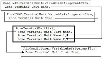
Figure 111. Zone Terminal Unit List Diagram
This alpha field specifies the name of the zone terminal unit list. This name must be specified in the AirConditioner:VariableRefrigerantFlow object.
This alpha field defines the name of the zone terminal unit used in a variable refrigerant air conditioner. The zone terminal unit must be connected to a zone using the ZoneHVAC:EquipmentConnections object. The terminal unit air inlet node is the same name as a zone exhaust node. The terminal unit air outlet node is the same name as a zone inlet node. The IDD is supplied with 20 fields for this. The object is extensible and you can change the IDD by adding more fields or, if you are using text editor for your input file, just add to the list of names.
Following is an example input for a ZoneTerminalUnitList object.
ZoneTerminalUnitList,
VRF Heat Pump TU List, !- Zone Terminal Unit List Name
TU3, !- Zone Terminal Unit Name 1
TU4, !- Zone Terminal Unit Name 2
TU1, !- Zone Terminal Unit Name 3
TU2, !- Zone Terminal Unit Name 4
TU5; !- Zone Terminal Unit Name 5
This section describes the radiative/convective zone equipment units. The following units are included in this section:
n ZoneHVAC:Baseboard:Convective:Electric
n ZoneHVAC:Baseboard:RadiantConvective:Water
n ZoneHVAC:Baseboard:RadiantConvective:Steam
n ZoneHVAC:Baseboard:RadiantConvective:Electric
n ZoneHVAC:Baseboard:Convective:Water
n ZoneHVAC:HighTemperatureRadiant
n ZoneHVAC:LowTemperatureRadiant:ConstantFlow
n ZoneHVAC:LowTemperatureRadiant:Electric
n ZoneHVAC:LowTemperatureRadiant:VariableFlow
The objective of this model is to calculate the convective and radiant heat transfer from water baseboard heaters to the people and the surfaces within a zone so that surface heat balances can take into account the radiant heat transfer to the surfaces and thus enhance the accuracy of thermal comfort predictions within the space. The radiant heat gains are distributed to the surfaces by fractions defined by user input.
A unique user assigned name for an instance of a hot water baseboard heater unit. Any reference to this unit by another object will use this name.
The name of the schedule (ref: Schedule) that denotes whether the hot water baseboard heater unit can run during a given hour. A schedule value greater than 0 (usually 1 is used) indicates that the unit can be on during the hour. A value less than or equal to 0 (usually 0 is used) denotes that the unit must be off for the hour.
This field is the name of the hot water inlet node for the baseboard heater.
This field is the name of the hot water outlet node for the baseboard heater.
This field is the rated average water temperature for the baseboard heater which is published in the manufacturer’s literature in degree Celsius. It typically ranges from 65.56C to 115.36C in the I=B=R rating document while the lowest allowable temperature is 32.22C. The default value is 87.78C. If the user does not enter this field, the default value is assumed.
This field is the maximum water volumetric flow rate in m3/sec. It can be autosized by EnergyPlus.
This field is the control tolerance for the unit heating output. The unit is controlled by matching the unit output to the zone demand. For hot water baseboards, the model must be numerically inverted to obtain a specified output. The convergence tolerance is the error tolerance used to terminate the numerical inversion procedure. Basically this is the fraction:
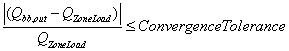
The default is 0.001.
This field specifies the fraction of radiant portion of heat transfer to the zone from the baseboard heater that is incident directly on people within the space. This has an impact on the predicted thermal comfort of the zone occupants. Note that although this energy is “radiant” it is actually modeled in the zone heat balance as convective energy (like an internal gain). The basic assumption here is that most radiant energy falling on people will most likely be rereleased to the zone air by convection. This is a simplification of reality, but it maintains the overall energy balance.
This field is the name of the first surface to which radiant heat transfer from the baseboard heater is distributed. Used in conjunction with the next field, it helps to define the distribution of the radiant energy on the surfaces within the zone. Note that up to 20 pairs of surface names and corresponding fractions may be entered for a single radiant heater system.
This field is paired with the preceding surface name (previous field) to define the fraction of radiant heat transfer leaving the baseboard heater that is incident on a particular surface. Users should take into account the directionality of baseboard heaters and their location when defining the value for this input field.
Note on Fraction of Radiant Energy Incident on People and to Surfaces
The radiant energy from the baseboard heater is defined by the total energy input to the baseboard heater from the water loop times the fraction radiant field shown above. This radiant energy is distributed to surfaces and people using the surface and fraction pairs and the fraction to people input by the user. These fractions to people and surfaces must add up to 1.0. In other words, in an input file, the following relation should be maintained by the user input:
![]()
An example IDF for the water baseboard is shown below.
ZoneHVAC:Baseboard:RadiantConvective:Water,
SPACE2-1 Baseboard, !- Baseboard Name
ReheatCoilAvailSched, !- Available Schedule
SPACE2-1 Zone Coil Water In Node, !- Inlet_Node
SPACE2-1 Zone Coil Water Out Node, !- Outlet_Node
76.67, !- Average Water Temperature {C}
0.063, !- Standard Water Mass Flow Rate {Kg/s}
3000.0, !- Rated Capacity {W}
0.0013, !- Max Water Volumetric Flow Rate {m3/s}
0.001, !- Convergence Tolerance
0.3, !- Fraction radiant
0.3, !- Fraction of radiant energy incident on people
C2-1, !- Surface 1 Name
0.1, !- Fraction of radiant energy from heater distributed to surface 1
F2-1, !- Surface 2 Name
0.2, !- Fraction of radiant energy from heater distributed to surface 2
SB21, !- surface 3 Name
0.1, !- fraction of radiant energy from heater distributed to surface 3
SB23, !- surface 4 Name
0.1, !- fraction of radiant energy from heater distributed to surface 4
SB25, !- surface 5 Name
0.1, !- fraction of radiant energy from heater distributed to surface 5
WR-1, !- surface 6 Name
0.1; !- fraction of radiant energy from heater distributed to surface 6
HVAC,Average,Baseboard Convective System Impact Rate[W]
HVAC,Average,Baseboard Heating Rate[W]
HVAC,Average,Baseboard Convective Heating Rate[W]
HVAC,Average,Baseboard Radiant Heating Rate[W]
HVAC,Sum,Baseboard Convective System Impact Energy[J]
HVAC,Sum,Baseboard Heating Energy[J]
HVAC,Sum,Baseboard Convective Heating Energy[J]
HVAC,Sum,Baseboard Radiant Heating Energy[J]
HVAC,Meter,Baseboard:EnergyTransfer [J]
This is the actual convective heat addition rate of the baseboard to the zone in Watts. This value includes the heat convected to the zone air from the baseboard unit, the heat radiated to people in the zone from the baseboard unit, and the additional convection from surfaces within the zone that have been heated by radiation from the baseboard unit. This value will be different from (and almost always less than) the next field.
This is the total heat addition rate of the baseboard to the zone it is serving in Watts.
This field reports the rate at which convective heat addition is transferred from the baseboard to the zone in Watts.
This field reports the rate at which radiant heat addition is transferred from the baseboard to the people and the surfaces within the zone in Watts.
This is the actual, total convective energy transferred directly and indirectly from the baseboard to the zone it is serving in Joules. Direct convective heat transfer includes the convective portion of the baseboard unit. Indirect convective heat transfer includes heat radiated to people that is then convected to the zone air and heat that is radiated to the surfaces and then convected to the zone air.
This is the total energy of the baseboard to the zone it is serving in Joules over the timestep being reported.
This field reports the amount of convective energy transferred from the baseboard directly to the zone air in Joules.
This field reports the amount of radiant energy transferred from the baseboard to the zone in Joules.
This meter report variable is the sum of the baseboard heat output from all the baseboards in the HVAC systems in the simulation.
This field reports the water mass flow rate at the inlet node of a baseboard unit.
This field reports the air mass flow rate at the inlet node of a baseboard unit.
This field reports the water temperatures at the inlet node of a baseboard unit.
This field reports the water temperatures at the outlet node of a baseboard unit.
This field reports the air temperatures at the inlet node of a baseboard unit.
This field reports the air temperatures at the outlet node of a baseboard unit.
The objective of this model is to calculate the convective and radiant heat transfer from steam baseboard heaters to the people and the surfaces within a zone so that surface heat balances can take into account the radiant heat transfer to the surfaces and thus enhance the accuracy of thermal comfort predictions within the space. The radiant heat gains are distributed to the surfaces by fractions defined by the user. Users are requested to provide degree of sub cooling to estimate the outlet conditions of the condensate.
A unique user assigned name for an instance of a steam baseboard heater unit. Any reference to this unit by another object will use this name.
The name of the schedule (ref: Schedule) that denotes whether the steam baseboard heater unit can run during a given hour. A schedule value greater than 0 (usually 1 is used) indicates that the unit can be on during the hour. A value less than or equal to 0 (usually 0 is used) denotes that the unit must be off for the hour.
This field is the name of the steam inlet node for the baseboard heater.
This field is the name of the steam outlet node for the baseboard heater.
This field is the temperature drop of the condensate in the coil of the baseboard heater. The steam condensates in the coil and changes the phase to the water, giving up the latent heat of steam to the air in the steam to air heat exchanger. The condensate due to the phase change then cools by certain degree in the coil, so that this amount of heat is added to the zone. The minimum value is 1.0 Celsius and default is 5.0 Celsius.
This field is the maximum steam volumetric flow rate in m3/sec. It can be autosized by EnergyPlus.
This field is the control tolerance for the unit heating output. The unit is controlled by matching the unit output to the zone demand. For steam baseboards, the model must be numerically inverted to obtain a specified output. The convergence tolerance is the error tolerance used to terminate the numerical inversion procedure. Basically this is the fraction:

The default is 0.001.
This field specifies what fraction of the power input to the baseboard heater is actually transferred to the space as radiant heat. The fraction should be between 0 and 1. This is the portion of the total power that is modeled as radiation. The portion that is radiant heat transfer from the baseboard heater is distributed to people and specific surfaces using the remaining fields. Note that the sum of the fractions in the remaining fields (people and surfaces) must equal 1.0 so that all the radiant power is distributed properly.
This field specifies the fraction of radiant portion of heat transfer to the zone from the baseboard heater that is incident directly on people within the space. This has an impact on the predicted thermal comfort of the zone occupants. Note that although this energy is “radiant” it is actually modeled in the zone heat balance as convective energy (like an internal gain). The basic assumption here is that most radiant energy falling on people will most likely be rereleased to the zone air by convection. This is a simplification of reality, but it maintains the overall energy balance.
The following two items are repeated up to a maximum of 20 surface/fraction pairs. At least one surface/fraction pair must appear in an input file. In other words, at least one surface must be identified as a recipient of radiant energy from the baseboard heater.
This field is the name of the first surface to which radiant heat transfer from the baseboard heater is distributed. Used in conjunction with the next field, it helps to define the distribution of the radiant energy on the surfaces within the zone. Note that up to 20 pairs of surface names and corresponding fractions may be entered for a single radiant heater system.
This field is paired with the preceding surface name (previous field) to define the fraction of radiant heat transfer leaving the baseboard heater that is incident on a particular surface. Users should take into account the directionality of baseboard heaters and their location when defining the value for this input field.
The radiant energy from the baseboard heater is defined by the total energy input to the baseboard heater from the steam loop times the fraction radiant field shown above. This radiant energy is distributed to surfaces and people using the surface and fraction pairs and the fraction to people input by the user. These fractions to people and surfaces must add up to 1.0. In other words, in an input file, the following relation should be maintained by the user input:
![]()
An example IDF for the steam baseboard is shown below.
ZoneHVAC:Baseboard:RadiantConvective:Steam,
Zone1Baseboard, !- Baseboard name
FanAndCoilAvailSched, !- On/off schedule
Steam Inlet Node, !- Steam inlet node
Steam Outlet Node, !- Steam outlet node
5.0, !- Degree of sub cooling in the coil {C}
autosize, !- Maximum steam volumetric flow rate {m3/s}
0.001, !- Tolerance
0.3, !- Fraction radiant
0.3, !- Fraction of radiant energy that is incident directly on people
OuterWall, !- Surface 1 Name
0.4, !- Fraction of radiant energy from heater distributed to surface 1
Ceiling, !- Surface 2 Name
0.1, !- Fraction of radiant energy from heater distributed to surface 2
InnerWall, !- Surface 3 Name
0.1, !- Fraction of radiant energy from heater distributed to surface 3
Floor, !- Surface 4 Name
0.1; !- Fraction of radiant energy from heater distributed to surface 4
HVAC,Average,Baseboard Convective System Impact Rate[W]
HVAC,Average,Baseboard Heating Rate[W]
HVAC,Average,Baseboard Convective Heating Rate[W]
HVAC,Average,Baseboard Radiant Heating Rate[W]
HVAC,Sum,Baseboard Convective System Impact Energy[J]
HVAC,Sum,Baseboard Heating Energy[J]
HVAC,Sum,Baseboard Convective Heating Energy[J]
HVAC,Sum,Baseboard Radiant Heating Energy[J]
HVAC,Meter,Baseboard:EnergyTransfer [J]
HVAC,Average,Baseboard Steam Mass Flow Rate [kg/s]
HVAC,Average,Baseboard Steam Inlet temperature [C]
HVAC,Average,Baseboard Steam Outlet temperature [C]
This is the actual convective heat addition rate of the baseboard to the zone in Watts. This value includes the heat convected to the zone air from the baseboard unit, the heat radiated to people in the zone from the baseboard unit, and the additional convection from surfaces within the zone that have been heated by radiation from the baseboard unit. This value will be different from (and almost always less than) the next field.
This is the total heat addition rate of the baseboard to the zone it is serving in Watts.
This field reports the rate at which convective heat addition is transferred from the baseboard to the zone in Watts.
This field reports the rate at which radiant heat addition is transferred from the baseboard to the people and the surfaces within the zone in Watts.
This is the actual, total convective energy transferred directly and indirectly from the baseboard to the zone it is serving in Joules. Direct convective heat transfer includes the convective portion of the baseboard unit. Indirect convective heat transfer includes heat radiated to people that is then convected to the zone air and heat that is radiated to the surfaces and then convected to the zone air.
This is the total energy of the baseboard to the zone it is serving in Joules over the time step being reported.
This field reports the amount of convective energy transferred from the baseboard directly to the zone air in Joules.
This field reports the amount of radiant energy transferred from the baseboard to the zone in Joules.
This meter report variable is the sum of the baseboard heat output from all the baseboards in the HVAC systems in the simulation.
This field reports the steam mass flow rate at the inlet node of a baseboard unit.
This field reports the steam temperatures at the inlet node of a baseboard unit.
This field reports the steam temperatures at the outlet node of a baseboard unit.
The electric baseboard heater is a component in the zone equipment simulation. Heat from this device is radiated to people and surfaces and also convected to the surrounding air. The electric baseboard model includes the impact of the radiant heat addition to people and surfaces so that the thermal comfort and surface heat balances are impacted. The component is controlled to meet any remaining zone load not met by other equipment baseboard operates to meet the remaining zone load and the total electric consumption is calculated by dividing by the efficiency of the baseboard.
A unique user assigned name for an instance of an electric baseboard heater unit. Any reference to this unit by another object will use this name.
The name of the schedule (ref: Schedule) that denotes whether the electric baseboard heater unit can run during a given hour. A schedule value greater than 0 (usually 1 is used) indicates that the unit can be on during the hour. A value less than or equal to 0 (usually 0 is used) denotes that the unit will be off for the hour.
This is the nominal, or maximum capacity, of this electric baseboard unit. This field may be autosized.
This is the overall electrical efficiency of the electric baseboard unit. The zone load met by this unit is divided by the electrical efficiency to obtain the total electric energy used.
This field specifies what fraction of the power input to the baseboard heater is actually transferred to the space as radiant heat. The fraction should be between 0 and 1. This is the portion of the total power that is modeled as radiation. The portion that is radiant heat transfer from the baseboard heater is distributed to people and specific surfaces using the remaining fields. Note that the sum of the fractions in the remaining fields (people and surfaces) must equal 1.0 so that all the radiant power is distributed properly.
This field specifies the fraction of the radiant portion of heat transfer to the zone from the baseboard heater that is incident directly on people within the space. This has an impact on the predicted thermal comfort of the zone occupants. Note that although this energy is “radiant” it is actually modeled in the zone heat balance as a convective energy (like an internal gain). The basic assumption here is that radiant energy falling on people will most likely be rereleased to the zone air by convection. This is a simplification of reality, but it maintains the overall energy balance.
The following two items are repeated up to a maximum of 20 surface/fraction pairs. At least one surface/fraction pair must appear in an input file. In other words, at least one surface must be identified as a recipient of radiant energy from the baseboard heater.
This field is the name of the first surface to which radiant heat transfer from the baseboard heater is distributed. Used in conjunction with the next field, it helps to define the distribution of the radiant energy on the surfaces within the zone. Note that up to 20 pairs of surface names and corresponding fractions may be entered for a single radiant heater system.
This field is paired with the preceding surface name (previous field) to define the fraction of radiant heat transfer leaving the baseboard heater that is incident on a particular surface. Users should take into account the directionality of baseboard heaters and their location when defining the value for this input field.
The radiant energy from the baseboard heater is defined by the total energy input to the baseboard heater times the fraction radiant field shown above. This radiant energy is distributed to surfaces and people using the surface and fraction pairs and the fraction to people input by the user. These fractions to people and surfaces must add up to 1.0. In other words, in an input file, the following relation should be maintained by the user input:
![]()
Below is an example input for an Electric Baseboard Heater.
ZoneHVAC:Baseboard:RadiantConvective:Electric,
Baseboard 1, !- Name
BB Schedule, !- Available schedule
5000, !- Nominal Capacity of the baseboard {W}
0.97, !- Efficiency of the baseboard
0.3, !- Fraction radiant
0.3, !- Fraction of radiant energy that is incident directly on people
EastWall, !- Surface 1 name
0.3, !- Fraction of radiant energy from heater distributed to surface 1
WestWall, !- Surface 2 name
0.1, !- Fraction of radiant energy from heater distributed to surface 2
NorthWall, !- Surface 3 name
0.1, !- Fraction of radiant energy from heater distributed to surface 3
SouthWall, !- Surface 4 name
0.1, !- Fraction of radiant energy from heater distributed to surface 4
Ceiling, !- Surface 5 name
0.1; !- Fraction of radiant energy from heater distributed to surface 5
HVAC,Average,Baseboard Convective System Impact Rate[W]
HVAC,Average,Baseboard Heating Rate[W]
HVAC,Average,Baseboard Radiant Heating Rate[W]
HVAC,Average,Baseboard Convective Heating Rate[W]
HVAC,Average,Baseboard Electric Power[W]
HVAC,Sum,Baseboard Convective System Impact Energy[J]
HVAC,Sum,Baseboard Heating Energy[J]
HVAC,Sum,Baseboard Radiant Heating Energy[J]
HVAC,Sum,Baseboard Convective Heating Energy[J]
HVAC,Sum,Baseboard Electric Consumption[J]
HVAC,Meter,Baseboard:EnergyTransfer [J]
HVAC,Meter,Heating:Electricity[J]
This is the actual convective heat addition rate of the baseboard to the zone in Watts. This value includes the heat convected to the zone air from the baseboard unit, the heat radiated to people in the zone from the baseboard unit, and the additional convection from surfaces within the zone that have been heated by radiation from the baseboard unit. This value will be different from (and almost always less than) the next field.
This is the total heating capacity of the baseboard in Watts.
This field reports the rate at which radiant heat addition is transferred from the baseboard to the people and the surfaces within the zone in Watts.
This field reports the rate at which convective heat addition is transferred from the baseboard to the zone in Watts.
This is the electric power required by the baseboard to the zone it is serving in Watts
This is the actual convective energy transferred directly and indirectly from the baseboard heater to the zone it is serving in Joules. Direct convective heat transfer includes the convective portion of the baseboard unit. Indirect convective heat transfer includes heat radiated to people that is then convected to the zone air and heat that is radiated to the surfaces and then convected to the zone air.
This is the total energy of the baseboard to the zone it is serving in Joules over the time step being reported.
This field reports the amount of radiant energy transferred from the baseboard to the zone in Joules.
This field reports the amount of convective energy transferred from the baseboard directly to the zone air in Joules.
This meter report variable is the sum of the baseboard heat output from all the electric baseboards in the HVAC systems in the simulation.
This meter report variable is the sum of the electric output from all the electric baseboards in the HVAC systems in the simulation.
The hot water baseboard heater is a component of zone equipment. The component is controlled to meet any remaining zone load not met by other equipment in the zone that have higher heating priority. The control is accomplished by throttling the hot water flow. Input resembles that for the simple heating coil: there is an availability schedule, an overall UA, and a maximum hot water mass flow rate. The unit is connected to a hot water loop (demand side) with an inlet and outlet node. Finally, there is the convergence tolerance, which is the tolerance on how closely the baseboard outlet will meet the zone load. Of course, this tolerance is relative to the zone load.
A unique user assigned name for an instance of a hot water baseboard heater unit. Any reference to this unit by another object will use this name.
The name of the schedule (ref: Schedule) that denotes whether the hot water baseboard heater unit can run during a given hour. A schedule value greater than 0 (usually 1 is used) indicates that the unit can be on during the hour. A value less than or equal to 0 (usually 0 is used) denotes that the unit must be off for the hour.
The name of the hot water inlet node for the baseboard heater.
The name of the hot water outlet node for the baseboard heater.
The overall heat transfer coefficient for the baseboard heater in watts per degree Celsius at design conditions. The U-Factor Times Area Value (UA) is used in an NTU - effectiveness calculation. An estimate of the UA can be obtained from:
![]()
where q is the heat transferred from water to the air in watts; Twater, avg is the average water temperature in degrees C; and Tair, avg is the average air temperature in degrees C. Or the LMTD temperature difference can be used.
The maximum hot water volumetric flow rate in m3/sec.
The control tolerance for the unit heating output. The unit is controlled by matching the unit output to the zone demand. For hot water baseboards, the model must be numerically inverted to obtain a specified output. The convergence tolerance is the error tolerance used to terminate the numerical inversion procedure. Basically this is the fraction:
The default is 0.001.
An example IDF for the hot water convective baseboard is shown below.
ZoneHVAC:Baseboard:Convective:Water,
Zone3Baseboard, ! name
FanAndCoilAvailSched, ! on/off schedule
Zone 3 Reheat Water Inlet Node, ! water inlet node
Zone 3 Reheat Water Outlet Node, ! water outlet node
500., ! UA
0.0013, ! maximum water flow rate m3/s
0.001; ! tolerance
HVAC,Average,Baseboard Heating Rate[W]
HVAC,Sum,Baseboard Heating Energy[J]
HVAC,Meter,Baseboard:EnergyTransfer [J]
This is the heat addition rate of the convective baseboard to the zone it is serving in Watts.
This is the heat addition of the convective baseboard to the zone it is serving in Joules over the timestep being reported.
This meter report variable is the sum of the baseboard heat output from all the baseboards in the HVAC systems in the simulation.
This field reports the water mass flow rate at the inlet node of a baseboard unit.
This field reports the air mass flow rate at the inlet node of a baseboard unit.
This field reports the water temperatures at the inlet node of a baseboard unit.
This field reports the water temperatures at the outlet node of a baseboard unit.
This field reports the air temperatures at the inlet node of a baseboard unit.
This field reports the air temperatures at the outlet node of a baseboard unit.
The electric baseboard heater is a component in the zone equipment simulation. The component is controlled to meet any remaining zone load not met by other equipment in the zone that have higher heating priority. The control is accomplished by taking the remaining zone load and dividing by the efficiency of the baseboard.
A unique user assigned name for an instance of a electric baseboard heater unit. Any reference to this unit by another object will use this name.
The name of the schedule (ref: Schedule) that denotes whether the electric baseboard heater unit can run during a given hour. A schedule value greater than 0 (usually 1 is used) indicates that the unit can be on during the hour. A value less than or equal to 0 (usually 0 is used) denotes that the unit must be off for the hour.
This is the nominal, or maximum capacity, of this electric baseboard unit.
This is the overall electrical efficiency of the electric baseboard. The zone load met by this unit is divided by the electrical efficiency to obtain the total electric energy used.
An example IDF for the electric convective baseboard is shown below.
ZoneHVAC:Baseboard:Convective:Electric,
Zone1Baseboard, !- Baseboard Name
FanAndCoilAvailSched, !- Available Schedule
5000, !- Nominal Capacity of the BaseBoard {W}
0.97; !- Efficiency of the BaseBoard
HVAC,Average,Baseboard Heating Rate[W]
HVAC,Sum,Baseboard Heating Energy[J]
HVAC,Meter,Baseboard:EnergyTransfer [J]
HVAC,Sum,Baseboard Electric Consumption[J]
HVAC,Average,Baseboard Electric Power[W]
HVAC,Meter,Heating:Electricity[J]
This is the heat addition rate of the electric convective baseboard to the zone it is serving in Watts.
This is the heat addition of the convective baseboard to the zone it is serving in Joules over the timestep being reported.
This meter report variable is the sum of the baseboard heat output from all the baseboards in the HVAC systems in the simulation regardless of Energy input.
This is the total electric consumption of the baseboard for the zone it is serving in Joules over the timestep being reported.
This is the electric power required by the baseboard to the zone it is serving in Watts.
This meter report variable is the sum of the electric output from all the electric baseboards in the HVAC systems in the simulation.
This low temperature radiant system (hydronic) is a component of zone equipment that is intended to model any “radiant system” where water is used to supply/remove energy to/from a building surface (wall, ceiling, or floor). The component is controlled to meet any remaining zone load not met by other equipment in the zone that have higher priority. The control is accomplished by throttling the hot or chilled water flow to the unit. Note that this system will only control based on the radiant system controls defined by this input syntax and not via a zone thermostat such as is used for forced air systems. Note also that because this unit does not require a thermostat that in cases where no other systems are serving the zone in which this system resides that it will use the heating equipment priority to determine which system will run first. If the radiant system is serving a zone with forced air equipment, the radiant system will follow the priority order established by the zone thermostat but will still base its response on the controls defined by the user for the radiant system.
This model covers a wide range of low temperature radiant systems: heating and/or cooling, panel or embedded pipes, etc. It is not intended to simulate high temperature electric or gas radiant heaters. Those devices will be handled by a separate model and different input syntax. Low temperature radiant systems that use electric resistance heating should also be defined using separate input syntax (ref: ZoneHVAC:LowTemperatureRadiant:Electric).
This field is an unique user assigned name for an instance of a hydronic low temperature radiant system. Any reference to this unit by another object will use this name.
This field is the name of the schedule (ref: Schedule) that denotes whether the hydronic low temperature radiant system can run during a given hour. A schedule value greater than 0 (usually 1 is used) indicates that the unit is available and can be on during the hour. A value less than or equal to 0 (usually 0 is used) denotes that the unit is not available and must be off for the hour.
This field is the name of the zone (Ref: Zone) in which the hydronic low temperature radiant system is principally located and intended to affect. A system that is between two zones will still act upon each zone; however, the zone name referenced here should be the zone that controls the radiant system response.
This field is the name of the surface (Ref: BuildingSurface) or surface list (Ref: ZoneHVAC:LowTemperatureRadiant:SurfaceGroup) in which the hydronic tubing is embedded/contained. This specification attaches the source or sink from the radiant system to a particular surface and the contribution of the system to the heat balances of that surface. If this field is a surface list, then the source or sink is attached to all of the surfaces in the list with the radiant system surface group defining the breakdown of how flow rate is split between the various surfaces. Only base surfaces (e.g., BuildingSurface:Detailed) are valid. Window/Door surfaces and Internal Mass are not valid surface types for embedded radiant systems.
This field is the inside diameter of the tubes through which water is circulated for the system being defined by this statement. The inside diameter should be recorded in meters and is used to determine the convective heat transfer from the water to the inside surface of the hydronic tubing.
This field is the total length of pipe embedded in the surface named above in the surface name field. The length of the tube should be entered in meters and is used to determine the effectiveness of heat transfer from the fluid being circulated through the tubes and the tube/surface. Longer tubing lengths result in more heat will be transferred to/from the radiant surface to the circulating fluid. Note that if the user elects to autosize this field that a standard zone thermostat such as would be used for a forced air system must be defined as autosizing calculations are based on the zone thermostat value and not on the radiant system control values.
This field specifies along with the throttling range and setpoint schedules how the user wishes to control the hydronic radiant system. The temperature denoted in the setpoint schedule can refer to one of five different temperatures: the zone mean air temperature, the zone mean radiant temperature, the zone operative temperature, the outdoor dry-bulb temperature, or the outdoor wet-bulb temperature. The choice of temperature is controlled by the current field—temperature control type. The user must select from the following options:
MeanAirTemperature
MeanRadiantTemperature
OperativeTemperature
OutdoorDryBulbTemperature
OutdoorWetBulbTemperature
Operative temperature for radiant system controls is the average of Mean Air Temperature and Mean Radiant Temperature. If the user does not select a control type, MeanAirTemperature control is assumed by EnergyPlus. See the throttling range and control temperature schedule fields below for more information.
This field is the maximum flow rate of hot water through the radiant system in m3/sec. The controls for the radiant system will vary the flow rate of hot water through the surface using zero flow and the maximum flow rate specified in this field as the lower and upper bounds, respectively. Note that if the user elects to autosize this field that a standard zone thermostat such as would be used for a forced air system must be defined as autosizing calculations are based on the zone thermostat value and not on the radiant system control values.
This field contains the name of the hot water inlet node to the radiant system. Note that this node name must also show up in the branch description when defining the plant demand side network in a manner identical to defining a heating coil.
This field contains the name of the hot water oulet node to the radiant system. Note that this node name must also show up in the branch description when defining the plant demand side network in a manner identical to defining a heating coil.
This field specifies the range of temperature in degrees Celsuis over which the radiant system throttles from zero flow rate up to the maximum defined by the maximum hot water flow rate field described above. The throttling range parameter is used in conjunction with the control temperature to define the response of the system to various zone conditions. The heating control temperature schedule specifies the “setpoint” temperature where the flow rate to the system is at half of the maximum flow rate. For example, if the heating control temperature setpoint is currently 15°C and the heating throttling range is 2°C, the water flow rate to the radiant system will be zero when the controlling temperature (MAT, MRT, Operative Temperature, ODB, or OWB; see control type field above) is at or above 16°C and the maximum flow rate when the controlling temperature is at or below 14°C. This represents a throttling range of 2°C around the setpoint of 15°C. In between 14°C and 16°C, the flow rate to the radiant system is varied linearly.
This field specifies the heating setpoint or control temperature for the radiant system in degrees Celsius. Used in conjunction with the previous field (heating control throttling range), it will define whether or not the system is running and the current flow rate. Water flow rate to the system is varied linearly around the setpoint temperature based on the throttling range and the maximum heating flow rate parameters (see above). It should be noted that this control schedule will allow different setpoint temperatures throughout the year for heating. The control of the radiant system is based solely on the heating control temperature schedule, the cooling control temperature schedule (see below), and the control temperature type listed above. The radiant system will not use any zone thermostat that might be used by other systems serving the zone in which the radiant system resides.
This field is the maximum flow rate of cold water through the radiant system in m3/sec. The controls for the radiant system will vary the flow rate of cold water through the surface using zero flow and the maximum flow rate specified in this field as the lower and upper bounds, respectively. Note that this field is optional and not required for a heating only system. Note also that if the user elects to autosize this field that a standard zone thermostat such as would be used for a forced air system must be defined as autosizing calculations are based on the zone thermostat value and not on the radiant system control values.
This field contains the name of the cold water inlet node to the radiant system. Note that this node name must also show up in the branch description when defining the plant demand side network in a manner identical to defining a cooling coil. As with the maximum cold water flow rate, this field is optional and not required for a heating only system.
This field contains the name of the cold water oulet node to the radiant system. Note that this node name must also show up in the branch description when defining the plant demand side network in a manner identical to defining a cooling coil. As with the maximum cold water flow rate, this field is optional and not required for a heating only system.
This field specifies the range of temperature in degrees Celsuis over which the radiant system throttles from zero flow rate up to the maximum defined by the maximum cold water flow rate field described above. The throttling range parameter is used in conjunction with the control temperature to define the response of the system to various zone conditions. The cooling control temperature schedule specifies the “setpoint” temperature where the flow rate to the system is at half of the maximum flow rate. For example, if the cooling control temperature setpoint is currently 25°C and the cooling throttling range is 2°C, the water flow rate to the radiant system will be zero when the controlling temperature (MAT, MRT, Operative Temperature, ODB, or OWB; see control type field above) is at or below 24°C and the maximum flow rate when the controlling temperature is at or above 26C. This represents a throttling range of 2°C around the setpoint of 25°C. In between 24°C and 26°C, the flow rate to the radiant system is varied linearly.
This field specifies the cooling setpoint or control temperature for the radiant system in degrees Celsius. Used in conjunction with the previous field (cooling control throttling range), it will define whether or not the system is running and the current flow rate. Water flow rate to the system is varied linearly around the setpoint temperature based on the throttling range and the maximum cooling flow rate parameters (see above). It should be noted that this control schedule will allow different setpoint temperatures throughout the year for cooling. The control of the radiant system is based solely on the heating control temperature schedule listed above, the cooling control temperature schedule, and the control temperature type listed above. The radiant system will not use any zone thermostat that might be used by other systems serving the zone in which the radiant system resides.
When radiant systems do cooling, there is the possibility that condensation will occur on the surface that is being cooled. This is due to the fact that the surface temperature may drop below the dew-point temperature of the space. When this occurs, condensation on the surface will occur. In EnergyPlus, users have several options for handling this situation including: Off and SimpleOff. When the user chooses the Off option, EnergyPlus will not do anything other than produce a warning message when condensation is predicted to occur. The program will simply continue on; no moisture will be removed from the zone air and there will be no adjustment of the surface temperature as a result of the condensation. When the user chooses the SimpleOff option, the program will predict cases where condensation will occur and shut-off the radiant system to avoid this situation. With this option, the users also have the opportunity to adjust when the system will shut down. This is specified with the next parameter (field: condensation differential parameter). This parameter is optional and EnergyPlus will use the SimpleOff strategy when this parameter is not specified.
This optional parameter is only valid with the SimpleOff condensation handling algorithm (see previous input parameter). It establishes the difference between the calculated dew-point temperature of the space and the allowed surface temperature to which the surface can drop before the radiant system shuts down in degrees Celsius. This parameter can be any positive, negative, or zero value. When this parameter is zero, the radiant system will shut down when the surface temperature drops to the dew-point temperature or below. When this parameter is positive, the radiant system will shut down when the surface is the number of degrees Celsius above the dew-point temperature. This allows some extra safety to avoid condensation. When this parameter is negative, the radiant system will shut down when the surface temperature is the number of degrees Celsius below the dew-point temperature. While not recommended, this strategy allows the user to simulate a situation where small amounts of condensation are tolerable.
An example IDF with a hydronic low temperature radiant system is shown below.
ZoneHVAC:LowTemperatureRadiant:VariableFlow,
Resistive Zone Radiant Floor, ! name of hydronic low temperature radiant system
RadiantSysAvailSched, ! availability schedule
Resistive Zone, ! Zone name (name of zone system is serving)
Zn001:Flr001, ! Surface name (name of surface system is embedded in)
0.012, ! Hydronic tubing inside diameter in meters
400.0, ! Hydronic tubing length (total length of pipe embedded in surf) in meters
MeanAirTemperature, ! control type (control on mean air temperature)
0.00008, ! maximum hot water flow in m3/s
Resistive Zone Radiant Water Inlet Node, ! heating water inlet node
Resistive Zone Radiant Water Outlet Node, ! heating water outlet node
2.0, ! heating throttling range in degrees Celsius
Radiant Heating Setpoints, ! heating setpoint temperature schedule
0.0012, ! maximum cold water flow in m3/s
Zone 1 Cooling Water Inlet Node, ! cooling water inlet node
Zone 1 Cooling Water Outlet Node, ! cooling water outlet node
2.0, ! cooling throttling range in degrees Celsius
Radiant Cooling Setpoints, ! cooling setpoint temperature schedule
SimpleOff, ! condensation control type
0.5; ! condensation control dewpoint offset
HVAC,Average,Hydronic Low Temp Radiant Heating Rate[W]
HVAC,Sum,Hydronic Low Temp Radiant Heating Energy[J]
HVAC,Average,Hydronic Low Temp Radiant Cooling Rate[W]
HVAC,Sum,Hydronic Low Temp Radiant Cooling Energy[J]
HVAC,Average,Hydronic Low Temp Radiant Water Mass Flow[kg/s]
HVAC,Average,Hydronic Low Temp Radiant Water Inlet Temp[C]
HVAC,Average,Hydronic Low Temp Radiant Water Outlet Temp[C]
HVAC,Sum,Hydronic Low Temp Radiant Time Condensation Occurring[s]
This field reports the heating input rate to the low temperature radiant system in Watts. This is the heat source to the surface that is defined as the radiant system. The heating rate is determined by the zone conditions and the control scheme defined in the user input.
This field reports the heating input to the low temperature radiant system in Joules. This is the heat source to the surface that is defined as the radiant system. The heating rate is determined by the zone conditions, the control scheme defined in the user input, and the timestep.
This field reports the cooling input rate to the low temperature radiant system in Watts. This is the heat sink to the surface that is defined as the radiant system. The cooling rate is determined by the zone conditions and the control scheme defined in the user input.
This field reports the cooling input to the low temperature radiant system in Joules. This is the heat sink to the surface that is defined as the radiant system. The cooling rate is determined by the zone conditions, the control scheme defined in the user input, and the timestep.
This field reports the mass flow rate of water through the low temperature radiant system in kilograms per second.
This field reports the temperature of water entering the low temperature radiant system in Celsius.
This field reports the temperature of water leaving the low temperature radiant system in Celsius.
This field reports the amount of time when condensation is occurring. When using the Off condensation control, this simply reports the amount of time when condensation occurs. When using the SimpleOff condensation control, this indicates the amount of time when the system has been shut off because of the potential danger of condensation.
This low temperature radiant system (hydronic) is a component of zone equipment that is intended to model any “radiant system” where water is used to supply/remove energy to/from a building surface (wall, ceiling, or floor). The component is controlled via control schedules as described in the syntax below and does not require a zone thermostat. Note that because this unit does not require a thermostat that in cases where no other systems are serving the zone in which this system resides that it will use the heating equipment priority to determine which system will run first. If the radiant system is serving a zone with forced air equipment, the radiant system will follow the priority order established by the zone thermostat but will still base its response on the controls defined by the user for the radiant system.
The constant flow system differs from the hydronic system describe above in what it controls. The hydronic system varies the flow rate through the radiant system based on some control temperature. The constant flow system keeps flow rate constant via a local circulation pump and varies the water temperature that is sent to the radiant system. This is accomplished with a mixing valve that is controlled by a sensor. This model covers a wide range of low temperature radiant systems: heating and/or cooling, panel or embedded pipes, etc. It is not intended to simulate high temperature electric or gas radiant heaters. Those devices will be handled by a separate model and different input syntax. Low temperature radiant systems that use electric resistance heating should also be defined using separate input syntax (ref: ZoneHVAC:LowTemperatureRadiant:Electric). Low temperature radiant systems that vary the flow rate through the radiant system should also be defined using separate input syntax (ref: ZoneHVAC:LowTemperatureRadiant:VariableFlow)
One of the other differences between this model and the variable flow hydronic radiant system is that the constant flow radiant system has a built-in local secondary loop. It will recirculate flow coming out of the system and mix this with flow from the loop to arrive at the desired inlet temperature to the radiant system (note that this model has the temperature sensor AFTER the pump to insure proper inlet temperature to the radiant system). The local loop also contains a pump which is assumed to be upstream of the radiant system and after the mixing valve. So, the local loop can have some recirculation. The flow from the main loop may also bypass the radiant system if more than enough flow is available and the main loop is also a constant flow system.
This field is an unique user assigned name for an instance of a constant flow low temperature radiant system. Any reference to this unit by another object will use this name.
This field is the name of the schedule (ref: Schedule) that denotes whether the constant flow low temperature radiant system can run during a given hour. A schedule value greater than 0 (usually 1 is used) indicates that the unit is available and can be on during the hour. A value less than or equal to 0 (usually 0 is used) denotes that the unit is not available and must be off for the hour.
This field is the name of the zone (Ref: Zone) in which the constant flow low temperature radiant system is principally located and intended to affect. A system that is between two zones will still act upon each zone; however, the zone name referenced here should be the zone that controls the radiant system response.
This field is the name of the surface (Ref: BuildingSurface:Detailed) or surface list (Ref: ZoneHVAC:LowTemperatureRadiant:SurfaceGroup) in which the hydronic tubing is embedded/contained. This specification attaches the source or sink from the radiant system to a particular surface and the contribution of the system to the heat balances of that surface. If this field is a surface list, then the source or sink is attached to all of the surfaces in the list with the radiant system surface group defining the breakdown of how flow rate is split between the various surfaces. Only base surfaces (BuildingSurface:Detailed) are valid. Window/Door surfaces and Internal Mass are not valid surface types for embedded radiant systems.
This field is the inside diameter of the tubes through which water is circulated for the system being defined by this statement. The inside diameter should be recorded in meters and is used to determine the convective heat transfer from the water to the inside surface of the hydronic tubing.
This field is the total length of pipe embedded in the surface named above in the surface name field. The length of the tube should be entered in meters and is used to determine the effectiveness of heat transfer from the fluid being circulated through the tubes and the tube/surface. Longer tubing lengths result in more heat being transferred to/from the radiant surface to the circulating fluid.
This field specifies along with setpoint (control) and water schedules how the user wishes to control the constant flow radiant system. The temperature denoted in the setpoint schedule can refer to one of five different temperatures: the zone mean air temperature, the zone mean radiant temperature, the zone operative temperature, the outdoor dry-bulb temperature, or the outdoor wet-bulb temperature. The choice of temperature is controlled by the current field—temperature control type. The user must select from the following options:
MeanAirTemperature
MeanRadiantTemperature
OperativeTemperature
OutdoorDryBulbTemperature
OutdoorWetBulbTemperature
Operative temperature for radiant system controls is the average of Mean Air Temperature and Mean Radiant Temperature. If the user does not select a control type, MeanAirTemperature control is assumed by EnergyPlus. See the throttling range and control temperature schedule fields below for more information.
This field is the maximum flow rate of water through the radiant system in m3/sec. This flow rate is held constant by the local component pump, but the user has the option of varying this flow rate via a schedule (see next input field). The constant flow system will accept this flow rate and control the inlet temperature based on the control and water temperature schedules defined below.
This field modifies the maximum flow rate of water through the radiant system in m3/sec. This input is “optional”. If the user does not enter a schedule, the flow rate through the radiant system is assumed to be constant during all hours that it is operating based on the value entered in the previous input field. Note that the values for this schedule must be between zero and one.
This numeric field contains the pump’s rated head in Pascals.
This numeric field contains the pump’s rated power consumption in Watts.
This numeric field contains the pump’s efficiency in decimal form (0 = 0%, 1 = 100%).
This numeric field contains the pump’s fraction of power loss to the fluid.
This field contains the name of the hot water inlet node to the radiant system. Note that this node name must also show up in the branch description when defining the plant demand side network in a manner identical to defining a heating coil.
This field contains the name of the hot water outlet node to the radiant system. Note that this node name must also show up in the branch description when defining the plant demand side network in a manner identical to defining a heating coil.
This field specifies the high water temperature in degrees Celsius for the temperature control of a constant flow radiant heating system. Water and control temperatures for heating work together to provide a linear function that determines the water temperature sent to the radiant system. The current control temperature (see Temperature Control Type above) is compared to the high and low control temperatures at the current time. If the control temperature is above the high temperature, then the system will be turned off and the water mass flow rate will be zero. If the control temperature is below the low temperature, then the inlet water temperature is set to the high water temperature. If the control temperature is between the high and low value, then the inlet water temperature is linearly interpolated between the low and high water temperature values. For more information and a graph of how the water and control schedules affect the system operation, please consult the Engineering Reference document.
This field specifies the low water temperature in degrees Celsius for the temperature control of a constant flow heating radiant system. For more information on its interpretation, see Heating High Water Temperature Schedule above.
This field specifies the high control temperature in degrees Celsius for the temperature control of a constant flow heating radiant system. For more information on its interpretation, see Heating High Water Temperature Schedule above.
This field specifies the low control temperature in degrees Celsius for the temperature control of a constant flow heating radiant system. For more information on its interpretation, see Heating High Water Temperature Schedule above.
This field contains the name of the cold water inlet node to the radiant system. Note that this node name must also show up in the branch description when defining the plant demand side network in a manner identical to defining a cooling coil. As with the maximum cold water flow rate, this field is optional and not required for a heating only system.
This field contains the name of the cold water outlet node to the radiant system. Note that this node name must also show up in the branch description when defining the plant demand side network in a manner identical to defining a cooling coil. As with the maximum cold water flow rate, this field is optional and not required for a heating only system.
This field specifies the high water temperature in degrees Celsius for the temperature control of a constant flow radiant cooling system. Water and control temperatures for heating work together to provide a linear function that determines the water temperature sent to the radiant system. The current control temperature (see Temperature Control Type above) is compared to the high and low control temperatures at the current time. If the control temperature is above the high temperature, then the inlet water temperature is set to the low water temperature. If the control temperature is below the low temperature, then system will be turned off and the water mass flow rate will be zero. If the control temperature is between the high and low value, then the inlet water temperature is linearly interpolated between the low and high water temperature values. For more information and a graph of how the water and control schedules affect the system operation, please consult the Engineering Reference document.
This field specifies the low water temperature in degrees Celsius for the temperature control of a constant flow cooling radiant system. For more information on its interpretation, see Cooling High Water Temperature Schedule above.
This field specifies the high control temperature in degrees Celsius for the temperature control of a constant flow cooling radiant system. For more information on its interpretation, see Cooling High Water Temperature Schedule above.
This field specifies the low control temperature in degrees Celsius for the temperature control of a constant flow cooling radiant system. For more information on its interpretation, see Cooling High Water Temperature Schedule above.
When radiant systems do cooling, there is the possibility that condensation will occur on the surface that is being cooled. This is due to the fact that the surface temperature may drop below the dew-point temperature of the space. When this occurs, condensation on the surface will occur. In EnergyPlus, users have several options for handling this situation including: Off and SimpleOff. When the user chooses the Off option, EnergyPlus will not do anything other than produce a warning message when condensation is predicted to occur. The program will simply continue on; no moisture will be removed from the zone air and there will be no adjustment of the surface temperature as a result of the condensation. When the user chooses the SimpleOff option, the program will predict cases where condensation will occur and shut-off the radiant system to avoid this situation. With this option, the users also have the opportunity to adjust when the system will shut down. This is specified with the next parameter (field: condensation differential parameter). This parameter is optional and EnergyPlus will use the SimpleOff strategy when this parameter is not specified.
This optional parameter is only valid with the SimpleOff condensation handling algorithm (see previous input parameter). It establishes the difference between the calculated dew-point temperature of the space and the allowed surface temperature to which the surface can drop before the radiant system shuts down in degrees Celsius. This parameter can be any positive, negative, or zero value. When this parameter is zero, the radiant system will shut down when the surface temperature drops to the dew-point temperature or below. When this parameter is positive, the radiant system will shut down when the surface is the number of degrees Celsius above the dew-point temperature. This allows some extra safety to avoid condensation. When this parameter is negative, the radiant system will shut down when the surface temperature is the number of degrees Celsius below the dew-point temperature. While not recommended, this strategy allows the user to simulate a situation where small amounts of condensation are tolerable.
An example IDF with a constant flow low temperature radiant system is shown below.
ZoneHVAC:LowTemperatureRadiant:ConstantFlow,
Resistive Zone Radiant Floor, !- name of CONSTANT FLOW low temperature radiant system
RadiantSysAvailSched, !- availability schedule
Resistive Zone, !- Zone name
Zn001:Flr001, !- Surface name or group
0.012, !- Hydronic tubing inside diameter {m}
400.0, !- Hydronic tubing length {m}
MeanAirTemperature, !- temperature control type
0.0004, !- maximum water volumetric flow rate {m3/s}
, !-schedule for flow rate (optional, non-existent means constant)
30000, !-Rated Pump Head in Pa
50, !-Rated Power Consumption in W
0.87, !-Motor Efficiency
0.1, !-Fraction of Motor Inefficiencies to Fluid Stream
Resistive Zone Radiant Water Inlet Node, !- heating water inlet node
Resistive Zone Radiant Water Outlet Node, !- heating water outlet node
RadHeatHighWaterTemp, !-high water temperature schedule
RadHeatLowWaterTemp, !-low water temperature schedule
RadHeatHighControlTemp, !-high control temperature schedule
RadHeatLowControlTemp, !-low control temperature schedule
Zone 1 Cooling Water Inlet Node, !- cooling water inlet node
Zone 1 Cooling Water Outlet Node, !- cooling water outlet node
RadCoolHighWaterTemp, !-cooling high water temperature schedule
RadCoolLowWaterTemp, !-cooling low water temperature schedule
RadCoolHighControlTemp, !- cooling high control temperature schedule
RadCoolLowControlTemp, !- cooling low control temperature schedule
SimpleOff, !- condensation control type
0.5; !- condensation control dewpoint offset
HVAC,Average,Constant Flow Low Temp Radiant Heating Rate[W]
HVAC,Sum,Constant Flow Low Temp Radiant Heating Energy[J]
HVAC,Average,Constant Flow Low Temp Radiant Cooling Rate[W]
HVAC,Sum,Constant Flow Low Temp Radiant Cooling Energy[J]
HVAC,Average,Constant Flow Low Temp Radiant Mass Flow[kg/s]
HVAC,Average,Constant Flow Low Temp Radiant Injection Mass Flow[kg/s]
HVAC,Average,Constant Flow Low Temp Radiant Recirculation Mass Flow[kg/s]
HVAC,Average,Constant Flow Low Temp Radiant Water Inlet Temp[C]
HVAC,Average,Constant Flow Low Temp Radiant Water Outlet Temp[C]
HVAC,Average,Constant Flow Low Temp Radiant Pump Water Inlet Temp[C]
HVAC,Average,Constant Flow Low Temp Radiant Pump Electric Power[W]
HVAC,Sum,Constant Flow Low Temp Radiant Pump Electric Consumption[J]
HVAC,Average,Constant Flow Low Temp Radiant Pump Water Mass Flow[kg/s]
HVAC,Average,Constant Flow Low Temp Radiant Pump Heat To Fluid[W]
HVAC,Sum,Constant Flow Low Temp Radiant Pump Heat To Fluid Energy[J]
HVAC,Sum,Constant Flow Low Temp Radiant Time Condensation Occurring[s]
This field reports the heating input rate to the low temperature radiant system in Watts. This is the heat source to the surface that is defined as the radiant system. The heating rate is determined by the zone conditions and the control scheme defined in the user input.
This field reports the heating input to the low temperature radiant system in Joules. This is the heat source to the surface that is defined as the radiant system. The heating rate is determined by the zone conditions, the control scheme defined in the user input, and the timestep.
This field reports the cooling input rate to the low temperature radiant system in Watts. This is the heat sink to the surface that is defined as the radiant system. The cooling rate is determined by the zone conditions and the control scheme defined in the user input.
This field reports the cooling input to the low temperature radiant system in Joules. This is the heat sink to the surface that is defined as the radiant system. The cooling rate is determined by the zone conditions, the control scheme defined in the user input, and the timestep.
This field reports the mass flow rate of water through the low temperature radiant system in kilograms per second. This should be identical to the pump flow rate for the system.
This field reports the mass flow rate of water that is injected into the radiant system from the main loop. A valve will control the injection and recirculation mass flow rates (see next field) to match the temperature controls specified by the user and dictated by the current simulation conditions.
This field reports the mass flow rate of water that is recirculated from the radiant system outlet and mixed with the injection flow from the main loop. A valve will control the injection and recirculation mass flow rates (see next field) to match the temperature controls specified by the user and dictated by the current simulation conditions.
This field reports the temperature of water entering the low temperature radiant system in Celsius. This may differ from the inlet node temperature for the component since this component has its own local secondary loop.
This field reports the temperature of water leaving the low temperature radiant system in Celsius. This may differ from the outlet node temperature for the component since this component has its own local secondary loop.
This field reports the temperature of water entering the low temperature radiant system pump in Celsius. This may differ from the inlet node temperature for the component since this component has its own local secondary loop. It is assumed that the pump is upstream of the radiant system.
This field reports the rate of electric power consumption for the pump which supplies flow to the constant flow radiant system in Watts.
This field reports the electric power consumption for the pump which supplies flow to the constant flow radiant system in Joules.
This field reports the mass flow rate of water through the low temperature radiant system pump in kilograms per second. This should be identical to the flow rate for the system.
This field reports the rate at which heat is added to the fluid stream as it passes through the pump in Watts. This heat is reflected in the radiant system inlet temperature which will be different from the pump inlet temperature if this field has a non-zero value.
This field reports the amount of heat energy added to the fluid stream as it passes through the pump in Joules. This heat is reflected in the radiant system inlet temperature which will be different from the pump inlet temperature if this field has a non-zero value.
This field reports the amount of time when condensation is occurring. When using the Off condensation control, this simply reports the amount of time when condensation occurs. When using the SimpleOff condensation control, this indicates the amount of time when the system has been shut off because of the potential danger of condensation.
This low temperature radiant system (electric) is a component of zone equipment that is intended to model any “radiant system” where electric resistance heating is used to supply energy (heat) to a building surface (wall, ceiling, or floor). The component is controlled by the radiant system controls that are defined in the syntax below and this control does not require the use of a zone thermostat unless the unit is being autosized. Note also that because this unit does not require a thermostat that in cases where no other systems are serving the zone in which this system resides that it will use the heating equipment priority to determine which system will run first. If the radiant system is serving a zone with forced air equipment, the radiant system will follow the priority order established by the zone thermostat but will still base its response on the controls defined by the user for the radiant system.
The control is accomplished by varying the electrical power supplied to the unit. This model covers either a radiant panel system or wires embedded in entire walls, floors, or ceilings. It is not intended to simulate high temperature electric or gas radiant heaters. Those devices will be handled by a separate model and different input syntax. Low temperature radiant systems that use water flowing through tubes to provide heat to the system should also be defined using separate input syntax (ref: Low Temp Radiant System:Hydronic).
This field is an unique user assigned name for an instance of an electric low temperature radiant system. Any reference to this unit by another object will use this name.
This field is the name of the schedule (ref: Schedule) that denotes whether the electric low temperature radiant system can operate during a given hour. A schedule value greater than 0 (usually 1 is used) indicates that the unit is available and can be on during the hour. A value less than or equal to 0 (usually 0 is used) denotes that the unit is not available and must be off for the hour.
This field is the name of the zone (Ref: Zone) in which the electric low temperature radiant system is principally located and intended to affect. A system that is between two zones will still act upon each zone; however, the zone name referenced here should be the zone that controls the radiant system response.
This field is the name of the surface (Ref: BuildingSurface) or surface list (Ref: ZoneHVAC:LowTemperatureRadiant:SurfaceGroup) in which the hydronic tubing is embedded/contained. This specification attaches the source or sink from the radiant system to a particular surface and the contribution of the system to the heat balances of that surface. If this field is a surface list, then the source or sink is attached to all of the surfaces in the list with the radiant system surface group defining the breakdown of how flow rate is split between the various surfaces. Only base surfaces (e.g. BuildingSurface:Detailed) are valid. Window/Door surfaces and Internal Mass are not valid surface types for embedded radiant systems.
This field is the maximum amount of electrical energy that can be converted to heat in this particular radiant system in Watts. The controls for the radiant system will vary the amount of power supplied to the surface between zero input and the maximum power specified in this field as the lower and upper bounds, respectively. Note that if the user elects to autosize this field that a standard zone thermostat such as would be used for a forced air system must be defined as autosizing calculations are based on the zone thermostat value and not on the radiant system control values.
This field specifies along with the throttling range and setpoint schedules how the user wishes to control the low temperature electric radiant system. The temperature denoted in the setpoint schedule can refer to one of three different temperatures: the zone mean air temperature, the zone mean radiant temperature, the zone operative temperature, the outdoor dry-bulb temperature, or the outdoor wet-bulb temperature. The choice of temperature is controlled by the current field—temperature control type. The user must select from the following options:
MeanAirTemperature
MeanRadiantTemperature
OperativeTemperature
OutdoorDryBulbTemperature
OutdoorWetBulbTemperature
Operative temperature for radiant system controls is the average of Mean Air Temperature and Mean Radiant Temperature. If the user does not select a control type, MeanAirTemperature control is assumed by EnergyPlus. See the throttling range and control temperature schedule fields below for more information.
This field specifies the range of temperature in degrees Celsuis over which the radiant system throttles from zero heat input via the electric resistance wires up to the maximum defined by the maximum electrical power field described above. The throttling range parameter is used in conjunction with the control temperature (see below) to define the response of the system to various zone conditions. The heating control temperature schedule specifies the “setpoint” temperature where the power input to the system is at half of the maximum power input. For example, if the heating control temperature setpoint is currently 15°C and the heating throttling range is 2°C, the electrical power supplied to the radiant system will be zero when the controlling temperature (MAT, MRT, Operative Temperature, ODB, or OWB; see control type field above) is at or above 16°C and the maximum power input when the controlling temperature is at or below 14°C. This represents a throttling range of 2°C around the setpoint of 15°C. In between 14°C and 16°C, the power input to the radiant system is varied linearly.
This field specifies the heating setpoint or control temperature for the radiant system in degrees Celsius. Used in conjunction with the previous field (heating throttling range), it will define whether or not the system is running and the current power input to the radiant surface. Power input to the system is varied linearly around the setpoint temperature based on the throttling range and the maximum electrical power parameters (see above). It should be noted that this control schedule will allow different setpoint temperatures throughout the year for heating. In addition, this schedule may be different that the thermostatic control schedule defined for overall operation of components serving the zone in which the radiant system is located. The thermostatic control determines whether or not there is a heating or cooling load in the space and thus whether the systems should be operating. This field simply controls the flow rate to the radiant system.
An example IDF with an electric low temperature radiant system is shown below.
ZoneHVAC:LowTemperatureRadiant:Electric, Zone 2 Radiant Floor,
RadiantPanelAvailSched , ! Availability schedule
EAST ZONE , ! Zone name (name of zone system is serving)
Zn002:Flr001 , ! Surface name (name of surface system is embedded in)
10000 , ! maximum electrical power to panel (in Watts)
MeanAirTemperature, ! control type (control on mean air temperature)
2.0 , ! heating throttling range (in C)
Radiant Heating Setpoints ; ! heating setpoint temperatures
HVAC,Average, Electric Low Temp Radiant Electric Power[W]
HVAC,Sum, Electric Low Temp Radiant Electric Consumption[J]
This field reports the rate at which electric energy is “burned” in the low temperature radiant system in Watts. This is the heat source to the surface that is defined as the radiant system. The heating rate is determined by the zone conditions and the control scheme defined in the user input.
This field reports the amount of electric energy “burned” in the low temperature radiant system in Joules. This is the heat source to the surface that is defined as the radiant system. The heating rate is determined by the zone conditions, the control scheme defined in the user input, and the timestep.
A low temperature radiant system (hydronic or electric) may consist of multiple active surfaces that are serving to condition the space. Surfaces that act serially can be specified as multiple radiant systems using the standard radiant system input described above. However, if the multiple surfaces act in parallet, the Radiant System Surface Group input line is used to specify which surfaces are acting in a coordinated fashion and how flow rate is split between the surfaces. This list of surfaces (the name it is assigned) replaces the name of a single surface in the radiant system input described above. Note that all of the surfaces within a single list must be a part of the same zone and that the zone of these surfaces must also match the zone the radiant system is attempting to condition.
This field is an unique user assigned name for the list of surfaces that are acting in coordination with one another. Any reference to this list by a radiant system will use this name.
The pairs of Surface Name, Flow Fraction to Surface are used in several objects. There can be up to 10 specified. The object is extensible so more can be added.
This field is the name of a surface in the zone being conditioned by the radiant system. Only base surfaces (walls, roofs, floors) are valid. Window/Door surfaces and Internal Mass are not valid surface types for embedded radiant systems.
This field is the fraction of the total radiant system flow rate that is being sent to this particular surface. Note that the Surface Name/Surface Flow Fraction pair can be repeated up to 10 times. Flow rate fractions must sum to unity, otherwise the program will not accept the input as valid.
An example IDF with an electric low temperature radiant system is shown below.
ZoneHVAC:LowTemperatureRadiant:SurfaceGroup,
Zone 1 Radiant Surfaces, !- name of surface list
Zn001:Flr001, !- Surface name 1
0.75, !- Flow fraction for surface 1
Zn001:Roof001, !- Surface name 2
0.25; !- Flow fraction for surface 2
The high temperature radiant system (gas-fired or electric) is a component of zone equipment that is intended to model any “high temperature” or “high intensity” radiant system where electric resistance or gas-fired combustion heating is used to supply energy (heat) to a building occupants directly as well as the building surfaces (wall, ceiling, or floor). The component is controlled by the radiant system controls defined in the syntax below and this control does not require the use of a zone thermostat unless the unit is being autosized. Note also that because this unit does not require a thermostat that in cases where no other systems are serving the zone in which this system resides that it will use the heating equipment priority to determine which system will run first. If the radiant system is serving a zone with forced air equipment, the radiant system will follow the priority order established by the zone thermostat but will still base its response on the controls defined by the user for the radiant system.
The control is accomplished by varying the electrical power supplied to or gas consumed by the unit. It is not intended to simulate low temperature electric or hydronic radiant systems. Those devices will be handled by a separate model and different input syntax (ref: the low temperature systems described elsewhere).
This field is an unique user assigned name for an instance of the high temperature radiant system. Any reference to this unit by another object will use this name.
This field is the name of the schedule (ref: Schedule) that denotes whether the high temperature radiant system can operate during a given hour. A schedule value greater than 0 (usually 1 is used) indicates that the unit is available and can be on during the hour. A value less than or equal to 0 (usually 0 is used) denotes that the unit is not available and must be off for the hour.
This field is the name of the zone (Ref: Zone) in which the high temperature radiant system is principally located and intended to affect.
This field is the maximum amount of energy (rate) that can be converted to heat in this particular radiant system in Watts. The controls for the radiant system will vary the amount of power supplied to the surface between zero input and the maximum power specified in this field as the lower and upper bounds, respectively. Note that if the user elects to autosize this field that a standard zone thermostat such as would be used for a forced air system must be defined as autosizing calculations are based on the zone thermostat value and not on the radiant system control values.
This field denotes the type of high temperature radiant heater: gas or electric. The user must specify this by inputting either the keyword “Gas” or “Electric” for this field.
This field is the combustion efficiency for a gas high temperature radiant heater. This value should be greater than 0 and less than or equal to 1. It is intended to take into account any potential inefficiencies in the combustion process inside the radiant heater. The heater gas consumption is the ratio of heater output over the combustion efficiency. This parameter has no meaning for an electric high temperature radiant heater and is ignored when the previous field is equal to “Electric”.
This field specifies what fraction of the power input to the high temperature radiant heater is actually radiant heat transfer. The fraction should be between 0 and 1. In conjunction with the next two parameters, it defines the breakdown of how the power input to the heater is distributed to the rest of the zone. The sum of these fractions must be less than or equal to 1. If the fractions are less than one, the remaining energy is added to the zone as convective heat transfer. The radiant heat transfer from the heat is distributed to people and surfaces using the distribution fractions listed below.
This field specifies the fraction of the power input to the high temperature radiant heater that is converted to a latent heat gain within the space. This may be appropriate when a combustion process produces moisture that is transferred into the space. The latent heat addition from a high temperature radiant heater is handled as any other latent heat gain within the space, affecting the moisture balance on the zone air.
This field specifies the fraction of power input to the high temperature radiant heater that is “lost”. This energy is a loss term, and this fraction of the input power has no effect on the zone heat balances.
This field specifies along with the throttling range and setpoint schedules how the user wishes to control the high temperature radiant system. The temperature denoted in the setpoint schedule can refer to one of three different temperatures: a mean air temperature, a mean radiant temperature, or an operative temperature. The choice of temperature is controlled by the current field—temperature control type. The user must select from the following options:
MeanAirTemperature
MeanRadiantTemperature
OperativeTemperature
MeanAirTemperatureSetpoint
MeanRadiantTemperatureSetpoint
OperativeTemperatureSetpoint
If the user does not select a control type, OperativeTemperature control is assumed by EnergyPlus. For the setpoint control strategies (those ending in Setpoint above), EnergyPlus will attempt to find the correct heater output to meet the heating setpoint temperature (see below) through iteration and interpolation. This will more closely match the operation of an actual thermostat, but it will require significantly longer execution times. For more information on the standard piecewise linear control algorithm used by the Mean Air Temperature, Mean Radiant Temperature, and Operative Temperature control types (the “non-Setpoint” controls), see the throttling range and control temperature schedule fields below for more information.
This field specifies the range of temperature in degrees Celsuis over which the radiant system throttles from zero heat input via the electric resistance wires up to the maximum defined by the maximum electrical power field described above. The throttling range parameter is used in conjunction with the control temperature (see below) to define the response of the system to various zone conditions. The heating control temperature schedule specifies the “setpoint” temperature where the power input to the system is at half of the maximum power input. For example, if the heating control temperature setpoint is currently 15°C and the heating throttling range is 2°C, the electrical power supplied to the radiant system will be zero when the controlling temperature (Mean Air Temperature, Mean Radiant Temperature, and Operative Temperature; see control type field above) is at or above 16°C and the maximum power input when the controlling temperature is at or below 14°C. This represents a throttling range of 2°C around the setpoint of 15°C. In between 14°C and 16°C, the power input to the radiant system is varied linearly.
This field specifies the heating setpoint or control temperature for the radiant system in degrees Celsius. Used in conjunction with the previous field (heating throttling range), it will define whether or not the system is running and the current power input to the radiant surface. Power input to the system is varied linearly around the setpoint temperature based on the throttling range and the maximum electrical power parameters (see above). It should be noted that this control schedule will allow different setpoint temperatures throughout the year for heating. In addition, this schedule may be different that the thermostatic control schedule defined for overall operation of components serving the zone in which the radiant system is located. The thermostatic control determines whether or not there is a heating or cooling load in the space and thus whether the systems should be operating. This field simply controls the flow rate to the radiant system.
This field specifies the fraction of radiant heat transfer to the zone from the radiant heater that is incident directly on people within the space. This has an impact on the predicted thermal comfort of the zone occupants. Note that since the thermal comfort models only use the results of the zone heat balances this energy is accounted for within the heat balance as convective energy, directly affecting the zone air heat balance. The basic assumption here is that most radiant energy falling on people will most likely be convected to the surroundings. This is a simplification of reality, but it maintains the overall energy balance.
The pairs of Surface Name, Fraction of Radiant Energy to Surface are used in several objects. There can be up to 20 specified.
This field is the name of the first surface to which radiant heat transfer from the high temperature radiant heater is distributed. Used in conjunction with the next field, it helps to define the distribution of the radiant energy on the surfaces within the zone. Note that up to 20 pairs of surface names and corresponding fractions may be entered for a single radiant heater system.
This field is paired with the preceding surface name (previous field) to define the fraction of radiant heat transfer leaving the high temperature radiant system that is incident on a particular surface. Users should take into account the directionality of high temperature radiant heaters and their location when defining the value for this input field. Note that the sum of all fractions plus the fraction of radiant energy incident on people must add up to less than or equal to 1.
An example IDF with a high temperature radiant system is shown below.
ZoneHVAC:HighTemperatureRadiant, Zone 2 Radiant Heater,
RadiantPanelAvailSched , ! Availability schedule
EAST ZONE , ! Zone name (name of zone system is serving)
10000 , ! maximum power input (in Watts)
Gas, ! type of heater (either gas or electric)
0.8, ! combustion efficiency (ignored for electric radiant heaters)
0.80, ! fraction radiant
0.00, ! fraction latent
0.00, ! fraction lost
OperativeTemperature, ! temperature control type (controls on operative temperature)
2.0 , ! heating throttling range (in C)
Radiant Heating Setpoints, ! heating setpoint temperatures
0.04, ! fraction of radiant energy that is incident directly on people
Zn002:Flr001, 0.80, ! fraction of radiant energy that is incident on the surface indicated
Zn002:Wall001, 0.04, ! fraction of radiant energy that is incident on the surface indicated
Zn002:Wall002, 0.04, ! fraction of radiant energy that is incident on the surface indicated
Zn002:Wall003, 0.04, ! fraction of radiant energy that is incident on the surface indicated
Zn002:Wall004, 0.04; ! fraction of radiant energy that is incident on the surface indicated
HVAC,Average, High Temperature Radiant Heating Rate[W]
HVAC,Sum, High Temperature Radiant Heating Energy[J]
HVAC,Average, High Temperature Radiant Gas Consumption Rate[W]
HVAC,Sum, High Temperature Radiant Gas Consumption[J]
HVAC,Average, High Temperature Radiant Electric Power[W]
HVAC,Sum, High Temperature Radiant Electric Consumption [J]
This field reports the rate at which energy is transferred from the high temperature radiant system to the zone in Watts. This rate is determined by the zone conditions and the control scheme defined in the user input. Note that this amount takes into account any combustion inefficiency and thus could be different that the gas consumption rate in a high temperature gas radiant system.
This field reports the amount of energy transferred from the high temperature gas radiant system to the zone in Joules. This amount is determined by the zone conditions, the control scheme defined in the user input, and the timestep. Note that this amount takes into account any combustion inefficiency and thus could be different that the gas consumption in a high temperature gas radiant system.
This field reports the rate at which gas is “burned” in a high temperature gas radiant system in Watts. This rate is determined by the zone conditions and the control scheme defined in the user input.
This field reports the amount of gas “burned” in a high temperature gas radiant system in Joules. This amount is determined by the zone conditions, the control scheme defined in the user input, and the timestep.
This field reports the rate at which electric energy is “burned” in a high temperature electric radiant system in Watts. This rate is determined by the zone conditions and the control scheme defined in the user input.
This field reports the amount of electric energy “burned” in a high temperature electric radiant system in Joules. This amount is determined by the zone conditions, the control scheme defined in the user input, and the timestep.
Ventilated slab systems in general use outdoor air to “precool” slabs with colder nighttime air. This method of precooling the thermal mass of a space can be very effective when nighttime temperatures are low and the mass of the system is high enough to provide a significant amount of cooling potential during the day to counteract internal heat gains within a zone. Nearly all ventilated slabs are simple systems such as that shown in the right side of Figure 112. The fan is shown in a blow through position, but the model will allow either a blow or draw through configuration.
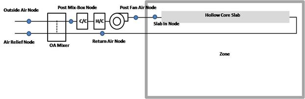
Figure 112. Ventilated Slab model - basic system
This field is a unique user assigned name for an instance of a ventilated slab system. Any reference to this unit by another object will use this name. Other objects that use this ventilated slab system will reference it by this name.
This field is the name of the schedule (ref: Schedule) that denotes whether the ventilated slab system can run during a given hour. A schedule value greater than 0 (usually 1 is used) indicates that the unit is available and can be on during the hour. A value less than or equal to 0 (usually 0 is used) denotes that the unit is not available and must be off for the hour.
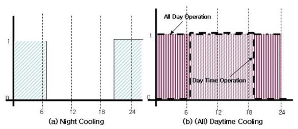
Figure 113. Example operating schedule for Ventilated Slab
This field is the name of the zone (Ref: Zone) in which the ventilated slab system is principally located and intended to affect. A system that is between two zones will still act upon each zone; however, the zone name referenced here should be the zone that controls the system response.
This field is the name of the surface (Ref: Surface) or surface list (Ref: ZoneHVAC:VentilatedSlab:SlabGroup) in which the hollow cores are embedded/contained. This specification attaches the source or sinks from the radiant system to a particular surface and the contribution of the system to the heat balances of that surface. If this field is a surface list, then the source or sink is attached to all of the surfaces in the list with the radiant system surface group defining the breakdown of how flow rate is split between the various surfaces. Only base surfaces (Walls, Roofs, Floors) are valid. Window/Door surfaces and Internal Mass are not valid surface types for embedded radiant systems.
This field allows the user to enter the maximum volumetric flow rate of air through the ventilated slab system in m3/sec. This parameter should be some real number greater than zero.
This field allows the user to control how outdoor air is used in the ventilated slab system. The ventilated slab system described by this syntax has its own outdoor air handler. The three options for outdoor air control are “VariablePercent”, “FixedTemperature” and “FixedAmount”. Those keywords are the only allowed choices for this parameter. In general, the variable percent control will attempt to vary the amount of outdoor air between some minimum and maximum schedules of fractions (see next two fields) to best meet the current heating or cooling load. The fixed temperature control will vary the amount of outdoor air between the minimum schedule (fraction of maximum, see next field) and 100% available outdoor air to come as close as possible to a desired mixed air temperature (see two fields down) that can be scheduled. The fixed amount control will fix the outdoor air flow rate as minimum outdoor air flow rate and schedule specified by the user and automatically set the maximum and minimum outside flow rate to be equal by ignoring the maximum outdoor air flow rate. More information on the controls and operation of the ventilated slab are given in the section above (preceding the IDF description).
This field allows the user to enter the minimum volumetric flow rate of outdoor air (in m3/sec) that will be brought in to the ventilated slab. The actual minimum outdoor air flow rate will be this number multiplied by the schedule value from the minimum outdoor air schedule. If “FixedAmount” type is selected as the outdoor air control strategy, the outdoor air flow rate will be fixed at the value of this field and the ventilated slab will automatically set the maximum and minimum outside flow rate to be equal by ignoring the maximum outdoor air flow rate.
This field contains a schedule name (ref: Schedule) that should contain values for the minimum outdoor air used by the ventilated slab system for IAQ or other reasons. Note that if the ventilated slab is scheduled off or if there is no load sensed in the zone that the system will not operate even to achieve the minimum air fraction. However, if the system is operating, it will always bring in at least this fraction of the minimum air flow rate (see minimum air flow rate field above). If “FixedAmount” type is selected as the outdoor air control strategy, the actual outdoor air flow rate will be this number multiplied by the minimum outdoor air flow rate in the field above. The ventilated slab will automatically set the maximum and minimum outdoor air schedule to be equal by ignoring the maximum outdoor air schedule.
This field allows the user to enter the maximum volumetric flow rate of outdoor air that can be brought into the ventilated slab in m3/sec. This parameter should be some real number greater than zero. Note that the value for this parameter may be less than the maximum air flow rate of the ventilated slab and this may affect the maximum fraction of outdoor air within the control strategy defined above. This parameter is an absolute maximum and will supercede any scheduled fraction of the ventilated slab maximum airflow rate. If “FixedAmount” type is selected as the outdoor air control strategy, this field will be ignored and be automatically set to be equal to the minimum outdoor air flow rate specified in the field above.
This field can have one of two meanings depending the type of control selected in the outdoor air control type parameter above. If “VariablePercent” or “FixedAmount” was selected, then this field is a schedule name (ref: Schedule) corresponding to a maximum air fraction schedule. Furthermore, if “FixedAmount” type is selected as the outdoor air control strategy, this field will be ignored and be automatically set to be equal to the minimum outdoor air fraction specified in the field below. Note that this is a fraction of the maximum airflow rate field (see parameter above) for the ventilated slab. If “FixedTemperature” control was selected, then this field is still a schedule name (ref: Schedule), but it corresponds to a schedule of mixed air temperatures that the outdoor air control will try to attain.
This field allows the user to control how the air is circulated using the ventilated slab system. The options for system configuration are
SlabOnly
SlabAndZone
SeriesSlabs
In the SlabOnly, the ventilation air is sent to the slab only and does not enter the zone. In the SlabAndZone, the air first enters the slab and then is delivered to the zone before returning to the system. With the SeriesSlabs option, the user specifies a list of slabs (ZoneHVAC:VentilatedSlab:SlabGroup). This list determines the order of slabs through which the air passes. In this option, air is not delivered to any zone.
This field is the inside diameter of the cores through which air is circulated for the system being defined by this statement. The inside diameter should be recorded in meters and is used to determine the convective heat transfer from the circulated air to the inside surface of the ventilated slab.
This field is the length of core embedded in the surface named above in the surface name field. In other words, this should be the distance that air travels as it through the slab. The length of the hollow core in the slab should be entered in meters and is used to determine the effectiveness of heat transfer from the air being circulated through the cores and the core inside surface. Longer core lengths result in more heat transferred to/from the radiant surface to the circulating fluid.
This field allows the user to specify how many cores there are in the ventilated slab. Air flow will be divided equally among the different cores.
This field specifies along with the throttling range and setpoint schedules how the user wishes to control the ventilated slab system. The temperature denoted in the set temperature schedule can refer to one of seven different temperatures: the zone mean air temperature, the zone mean radiant temperature, the zone operative temperature, the surface temperature of the ventilated slab, the outdoor dry-bulb temperature, the outdoor wet-bulb temperature, or the dewpoint temperature of zone mean air temperature. The choice of temperature is controlled by the current field—temperature control type. The user must select from the following options:
MeanAirTemperature
MeanRadiantTemperature
OperativeTemperature
OutdoorDryBulbTemperature
OutdoorWetBulbTemperature
SurfaceTemperature
ZoneAirDewPointTemperature
If the user does not select a control type, MeanAirTemperature control is assumed by EnergyPlus. See the control temperature schedule fields below for more information.
This field specifies the high air temperature in degrees Celsius for the temperature control of a ventilated slab system. Air and control temperatures for heating work together to provide a linear function that determines the air temperature sent to the ventilated slab. The current control temperature (see Temperature Control Type above) is compared to the high and low control temperatures at the current time. If the control temperature is above the high temperature, then the inlet air temperature is set to the low air temperature. If the control temperature is below the low temperature, then the inlet air temperature is set to the high air temperature. If the control temperature is between the high and low value, then the inlet air temperature is linearly interpolated between the low and high air temperature values.
This field specifies the low air temperature in degrees Celsius for the temperature control of a ventilated slab. For more information on its interpretation, see Heating High Air Temperature Schedule above.
This field specifies the high control temperature in degrees Celsius for the temperature control of a ventilated slab. For more information on its interpretation, see Heating High Air Temperature Schedule above.
This field specifies the low control temperature in degrees Celsius for the temperature control of a ventilated slab. For more information on its interpretation, see Heating High Air Temperature Schedule above.
This field specifies the high air temperature in degrees Celsius for the temperature control of a ventilated slab system. Air and control temperatures for cooling work together to provide a linear function that determines the air temperature sent to the ventilated slab system. The current control temperature (see Temperature Control Type above) is compared to the high and low control temperatures at the current time. If the control temperature is above the high temperature, then the inlet air temperature is set to the low air temperature. If the control temperature is below the low temperature, then the inlet air temperature is set to the high air temperature. If the control temperature is between the high and low value, then the inlet air temperature is linearly interpolated between the low and high air temperature values.
This field specifies the low air temperature in degrees Celsius for the temperature control of a constant flow cooling radiant system. For more information on its interpretation, see Cooling High Air Temperature Schedule above.
This field specifies the high control temperature in degrees Celsius for the temperature control of a constant flow cooling radiant system. For more information on its interpretation, see Cooling High Air Temperature Schedule above.
This field specifies the low control temperature in degrees Celsius for the temperature control of a ventilated slab system. For more information on its interpretation, see Cooling High Air Temperature Schedule above.
This field is a node name used to identify the node that serves as the zone return air inlet to the ventilated slab system. This node is one of the inlets to the outdoor air mixer which is implicit in the ventilated slab system model. For “SlabAndZone” configuration, the Return Air Node will typically be the same node as a zone exhaust node. For “SlabOnly” or “SeriesSlabs” configuration, this node name is required but will have zero flow.
This field is a node name used to identify the node that serves as the inlet of the ventilated slab or series of slabs, after the outdoor air mixer, fan, and optional coils.
This field is a node name used to identify the node that serves as the outlet from the ventilated slab system to the zone when using the “SlabAndZone” configuration. It is the node exiting the slab section of the system. This node will typically be the same node as a zone inlet node. In the case of “SlabOnly” or “SeriesSlabs” configuration, this field will be ignored and it should be left BLANK.
This field is a node name used to identify the node associated with fresh outdoor air brought into the ventilated slab system outdoor air mixer. This node should also be specified in an OutdoorAir:Node or OutdoorAir:NodeList object.
This field is a node name used to identify the node associated with air exhausted out of the ventilated slab system to the outdoor environment.
This field is a node name used to identify the node associated with the “mixed” air of the ventilated slab. These conditions are post-“mixing box” since they are the conditions of the fraction of return air combined with the outdoor air. Since this is a simple system, this can also be viewed as the conditions of the air being sent to the coils.
This field is a node name used to identify the node that serves as the air outlet from the fan.
This field is the name of a fan (ref: Fan:ConstantVolume) that is part of the ventilated slab system. This name links the ventilated slab to particular fan data entered elsewhere in the input data file. A fan name is required since it is the prime mover of air in the ventilated slab system.
This field allows the user to specify the coil operating options as one of the following options:
None
Heating
Cooling
HeatingAndCooling
If None is selected, the ventilated slab does not have any coils, and any other input will be ignored. If either Heating or Cooling is selected, only a heating or cooling coil, respectively, is present. Thus, only four more inputs will be expected. If HeatingAndCooling is selected, both heating and cooling coil input must be entered, and the ventilated slab will have both a heating and a cooling coil.
This field is the type of coil (ref: Coil:Heating:Water, Coil:Heating:Electric, Coil:Heating:Gas, Coil:Heating:Steam) that is used for heating in the ventilated slab system. This field must be one of the following keywords: Coil:Heating:Water, Coil:Heating:Electric, Coil:Heating:Gas, Coil:Heating:Steam. It is used in conjunction with the heating coil name (see next field) to specify the heating coil present within the system.
This field is the name of the heating coil that is part of the ventilated slab system. It is assumed that there is always some sort of heating coil associated with a ventilated slab system. This name links the ventilated slab to particular heating coil data entered elsewhere in the input data file.
This field corresponds to the water inlet node to the heating coil for a water coil. The water inlet node controls how a water heating coil operates. This field is ignored/not needed for gas and electric heating coils.
This field is the name of the cooling coil (ref: Coil:Cooling:Water, Coil:Cooling:Water:DetailedGeometry, CoilSystem:Cooling:Water:HeatExchangerAssisted) that is part of the ventilated slab system. This name links the ventilated slab system to particular cooling coil data entered elsewhere in the input data file. If no cooling coil is present, the previous field may be followed by a semi-colon and the remaining parameters in this statement may be ignored.
This field is the name of the cooling coil that is part of the ventilated slab system. It is assumed that there is always some sort of cooling coil associated with a ventilated slab system. This name links the ventilated slab to particular cooling coil data entered elsewhere in the input data file.
This field corresponds to the water inlet node to the cooling coil. The water inlet node controls how a water cooling coil operates and is required for the ventilated slab system that has a cooling coil associated with it to function properly.
An example IDF with a ventilated slab is shown below.
ZoneHVAC:VentilatedSlab,
Zone4VentSlab, !- Name
VentSlabAvailability, !- Availability Schedule Name
SPACE4-1, !- Zone Name
F4-1, !- Surface Name or Radiant Surface Group Name
0.84, !- Maximum Air Flow Rate {m3/s}
VariablePercent, !- Outdoor Air Control Type
0.168, !- Minimum Outdoor Air Flow Rate {m3/s}
U2MinOASched, !- Minimum Outdoor Air Schedule Name
0.84, !- Maximum Outdoor Air Flow Rate {m3/s}
VentSlabMaxOA, !- Maximum Outdoor Air Fraction or Temperature Schedule Name
SlabAndZone, !- System Configuration Type
0.050, !- Hollow Core Inside Diameter {m}
15.0, !- Hollow Core Length {m}
50.0, !- Number of Cores
MeanRadiantTemperature, !- Temperature Control Type
VentSlabHotHighAir, !- Heating High Air Temperature Schedule Name
VentSlabHotLowAir, !- Heating Low Air Temperature Schedule Name
VentSlabHotHighControl, !- Heating High Control Temperature Schedule Name
VentSlabHotLowControl, !- Heating Low Control Temperature Schedule Name
VentSlabCoolHighAir, !- Cooling High Air Temperature Schedule Name
VentSlabCoolLowAir, !- Cooling Low Air Temperature Schedule Name
VentSlabCoolHighControl, !- Cooling High Control Temperature Schedule Name
VentSlabCoolLowControl, !- Cooling Low Control Temperature Schedule Name
Zone4VentSlabReturnAirNode, !- Return Air Node Name
Zone4VentslabSlabInNode, !- Slab In Node Name
Zone4Inlets, !- Zone Supply Air Node Name
Zone4VentSlabOAInNode, !- Outdoor Air Node Name
Zone4VentSlabExhNode, !- Relief Air Node Name
Zone4VentSlabOAMixerOutletNode, !- Outdoor Air Mixer Outlet Node Name
Zone4VentSlabFanOutletNode, !- Fan Outlet Node Name
Zone4VentSlabFan, !- Fan Name
HeatingAndCooling, !- Coil Option Type
Coil:Heating:Electric, !- Heating Coil Object Type
Zone4VentSlabHeatingCoil,!- Heating Coil Name
, !- Hot Water or Steam Inlet Node Name
Coil:Cooling:Water, !- Cooling Coil Object Type
Zone4VentSlabCoolingCoil,!- Cooling Coil Name
Zone4VentSlabChWInletNode; !- Cold Water Inlet Node Name
HVAC,Average,Ventilated Slab Radiant Heating Rate [W]
HVAC,Sum,Ventilated Slab Radiant Heating Energy [J]
HVAC,Average,Ventilated Slab Radiant Cooling Rate [W]
HVAC,Sum,Ventilated Slab Radiant Cooling Energy [J]
HVAC,Average,Ventilated Slab Coil Heating Rate [W]
HVAC,Sum,Ventilated Slab Coil Heating Energy [J]
HVAC,Average,Ventilated Slab Total Coil Cooling Rate [W]
HVAC,Sum,Ventilated Slab Total Coil Cooling Energy [J]
HVAC,Average,Ventilated Slab Sensible Coil Cooling Rate [W]
HVAC,Sum,Ventilated Slab Sensible Coil Cooling Energy [J]
HVAC,Average,Ventilated Slab Latent Coil Cooling Rate [W]
HVAC,Sum,Ventilated Slab Latent Coil Cooling Energy [J]
HVAC,Average,Ventilated Slab Air Mass Flow [kg/s]
HVAC,Average, Ventilated Slab Fan Electric Power [W]
HVAC,Sum,Ventilated Slab Fan Electric Consumption [J]
HVAC,Average,Ventilated Slab Slab Inlet Air Temperature [C]
HVAC,Average,Ventilated Slab Slab Outlet Air Temperature [C]
HVAC,Average,Ventilated Slab Zone Inlet Air Temperature [C]
HVAC,Average,Ventilated Slab Slab Return Air Temperature [C]
HVAC,Average,Ventilated Slab Slab Fan Outlet Air Temperature [C]
This field reports the radiant heating input rate of the ventilated slab system to the zone it is serving in Watts. This is determined by outlet and zone air conditions and the mass flow rate through the ventilated slab system.
This field is the heating radiant input of the ventilated slab system to the zone it is serving in Joules over the timestep being reported. This is determined by outlet and zone air conditions, the mass flow rate through the ventilated slab system, and the timestep.
This field reports the radiant cooling input rate to the ventilated slab system in Watts. This is the heat sink to the surface that is defined as the ventilated slab system. The cooling rate is determined by the zone conditions and the control scheme defined in the user input.
This field reports the radiant cooling input to the ventilated slab system in Joules. This is the heat sink to the surface that is defined as the radiant system. The cooling rate is determined by the zone conditions, the control scheme defined in the user input, and the timestep.
This field reports the heating input rate of the heating coil of ventilated slab system the zone it is serving in Watts. This is determined by return air and zone air conditions and the mass flow rate through the ventilation slab system.
This field is the heating output of the heating coil of the ventilated slab system the zone it is serving in Joules over the timestep being reported. This is determined by return air and zone air conditions, the mass flow rate through the ventilation slab system, and the timestep.
This field reports the total cooling (sensible plus latent) output rate of the cooling coil of the ventilated slab system to the zone it is serving in Watts. This is determined by outlet and zone air conditions and the mass flow rate through the ventilation slab system.
This field is the total cooling (sensible plus latent) output of the cooling coil of the ventilated slab system to the zone it is serving in Joules over the timestep being reported. This is determined by outlet and zone air conditions, the mass flow rate through the ventilation slab system, and the timestep.
This field reports the sensible cooling output rate of the cooling coil of the ventilated slab system to the zone it is serving in Watts. This is determined by outlet and zone air conditions and the mass flow rate through the ventilation slab system.
This field is the sensible cooling output of the cooling coli of the ventilated slab system to the zone it is serving in Joules over the timestep being reported. This is determined by outlet and zone air conditions, the mass flow rate through the ventilation slab system, and the timestep.
This field reports the latent cooling output rate of the cooling coil of the ventilated slab system to the zone it is serving in Watts. This is determined by outlet and zone air conditions and the mass flow rate through the ventilation slab system.
This field is the latent cooling output of the cooling coli of the ventilated slab system to the zone it is serving in Joules over the timestep being reported. This is determined by outlet and zone air conditions, the mass flow rate through the ventilation slab system, and the timestep.
This field reports the mass flow rate of air through the ventilated slab system in kilograms per second.
This field reports the electric power consumption rate of the fan of the ventilated slab system in Watts.
This field reports the electric power consumed by the fan of the ventilated slab system over the timestep in Joules.
This field reports the temperature of air entering the ventilated slab system in Celsius.
This field reports the temperature of air leaving the ventilated slab system in Celsius.
This field reports the temperature of air entering the zone in Celsius.
This field reports the temperature of air leaving the zone in Celsius. When system does not circulate air to zone(“SlabOnly” Configuration), the slab outlet temperature and return air temperature will be the same.
This field reports the fan outlet air temperature for the ventilated slab system in Celsius.
A ventilated slab system may consist of multiple active slabs that are serving to condition the zone. Slabs that act serially can be specified as multiple radiant systems using the standard ventilated slab input described above. This list of surfaces (the name it is assigned) replcaces the name of a single surface in the ventilated slab system input described above.
This field is a unique user assigned name for the list of surfaces that are acting in coordination with one another. Any reference to this list by a ventilated slab system will use this name.
This field is the name of the zone in which the surface is principally located and intended to affect.
This field is the name of a surface in the zone being conditioned by the ventilated slab system. Only base surfaces like walls, floors and roofs are valid. Door/Window Surface and Internal Mass are not valid surface types for the ventilated slab system.
This field is the inside diameter of the cores through which air is circulated for the surface being defined by this statement. The inside diameter should be recorded in meters and is used to determine the convective heat transfer from the circulated air to the inside surface of the ventilated slab.
This field is the length of core embedded in the surface named above in the surface name field. In other words, this should be the distance that air travels as it through the slab. The length of the hollow core in the surface should be entered in meters and is used to determine the effectiveness of heat transfer from the air being circulated through the cores and the core inside surface. Longer core lengths result in more heat transferred to/from the radiant surface to the circulating fluid.
This field allows the user to specify how many cores there are in the ventilated slab. Air flow will be divided equally among the different cores.
This field is a node name (character string) used to identify the node that serves as the inlet (air side) to the surface. In EnergyPlus, nodes represent points between components or at various points in the loops. While a node name may be referenced more than once in an input data file, each node must have a unique name.
This field is a node name (character string) used to identify the node that serves as the outlet (air side) of the surface. In EnergyPlus, nodes represent points between components or at various points in the loops. While a node name may be referenced more than once in an input data file, each node must have a unique name.
An Example IDF with a ventilated slab system is shown below
ZoneHVAC:VentilatedSlab:SlabGroup,
Z125, !- Name
SPACE1-1, !- Zone 1 Name
C1-1, !- Surface 1 Name
0.05, !- Core Diameter for Surface 1
30, !- Core Length for Surface 1
20, !- Core Numbers for Surface 1
Z1VentslabIn, !- Slab In Node Name for Surface 1
Z1VentSlabout, !- Slab Outlet Node Name for Surface 1
SPACE2-1, !- Zone 2 Name
C2-1, !- Surface 2 Name
0.05, !- Core Diameter for Surface 2
15, !- Core Length for Surface 2
20, !- Core Numbers for Surface 2
Z2VentSlabIn, !- Slab In Node Name for Surface 2
Z2VentSlabOut, !- Slab Outlet Node Name for Surface 2
SPACE5-1, !- Zone 3 Name
C5-1, !- Surface 3 Name
0.05, !- Core Diameter for Surface 3
30, !- Core Length for Surface 3
20, !- Core Numbers for Surface 3
Z5VentSlabIn, !- Slab In Node Name for Surface 3
Z5VentSlabOut; !- Slab Outlet Node Name for Surface 3
There are two ways to model a supermarket refrigeration system. The first, and simplest, approach models the combination of compressor(s) and condenser as a single refrigeration compressor rack object. (A list is used to enter multiple case or walk-in names.)
For the first approach, the input objects needed are:
n One Refrigeration:CompressorRack object
n At least one refrigeration load, which may be any combination of:
n Refrigeration:Case or
n Refrigeration:WalkIn or
n Refrigeration:CaseAndWalkInList objects .
The second approach requires more input objects but also allows the user to model more complex systems. This detailed approach must be used whenever loads are transferred from one system to another, such as with secondary loops, cascade condensers, or mechanical subcoolers. Again lists are used to enter multiple load or compressor names.
For the detailed approach, the input objects needed are:
n One Refrigeration:System object
n At least one refrigeration load object which may include any combination of:
n Refrigeration:Case,
n Refrigeration:WalkIn,
n Refrigeration:CaseAndWalkInList (may include any combination of cases and walk in cooler names, OR, a list of air chiller names)
n Refrigeration:SecondarySystem,
n Refrigeration:Condenser:Cascade (as a load, cooling a lower-temperature system) objects,
n Refrigeration:TransferLoadList (may include cascade condenser loads and/or secondary loop loads)
n Refrigeration:AirChiller
n At least one Refrigeration:Compressor object (multiple compressors are entered using a Refrigeration:CompressorList),
n One condenser object which may be either:
n Refrigeration:Condenser:AirCooled,
n Refrigeration:Condenser:EvaporativeCooled,
n Refrigeration:Condenser:WaterCooled, or
n Refrigeration:Condenser:Cascade (rejecting heat from this system)
n The object Refrigeration:Subcooler may optionally be included to describe either a liquid suction or mechanical subcooler.
Output variables are also available to describe the total heat exchange between all refrigeration objects and the zones containing these objects. These variables are described at the end of this section after all the refrigeration objects.
The refrigeration compressor rack object works in conjunction with the refrigeration case and walkin objects (Ref. Refrigeration:Case and Refrigeration:WalkIn) to simulate the performance of a refrigerated case system. This object models the electric consumption of the rack compressors and the condenser fans. Heat removed from the refrigerated cases, walkins, and compressor/condenser fan heat can be rejected either outdoors or to a zone. Compressor rack waste heat can also be reclaimed for use by an optional air- or water-heating coil (Ref. Coil:Heating:Desuperheater and Coil:WaterHeating:Desuperheater).
If heat is rejected outdoors, condenser cooling can either be accomplished by direct air flow, evaporative water cooling, or a by water-cooled condenser with appropriate plant loop piping. With evaporative cooling, water is sprayed through the air stream to effectively lower the air temperature experienced by the condenser coil as a result of water evaporation. The use of a water-cooled condenser requires the definition of a plant loop to supply cooling to the condenser. Waste heat can be reclaimed and stored using a water storage device.
The inputs for the compressor rack object include a name, the heat rejection location, the compressor rack coefficient of performance (COP) at design conditions, the design condenser fan power, and the type of condenser cooling. The model requires two curve objects to describe performance at off-design conditions. If the condenser is water-cooled, the inlet and outlet node names as well as the water outlet temperature schedule name are required. If the condenser has evaporative cooling, additional inputs for evaporative condenser effectiveness, condenser air flow rate, basin heater parameters, water pump power, water source, and an evaporative cooling availability schedule are available. The names of refrigerated cases and walkins connected to the compressor rack are the final inputs to the model.
A unique user-assigned name for an instance of a refrigeration compressor rack. Any reference to this compressor rack by another object will use this name.
The location of the compressor rack’s condenser. The compressor rack condenser heat can be directed “Outdoors” to model an outdoor air or water-cooled condenser or “Zone” to model a condenser located in a zone (e.g., a stand-alone packaged refrigerated case with integral condenser located in a conditioned zone). The default for this field is “Outdoors”. If the heat rejection location is “Zone” and no walk-in coolers are served by this compressor rack, then all refrigerated cases connected to this compressor rack must be located in the same zone. If however, walk-in coolers are also served by this compressor rack, then the heat rejection zone name must be specified (see Heat Rejection Zone Name field below) and cases and walk-ins can be located in multiple zones.
NOTE: When modeling a heat reclaim coil, the heat rejection location must be “Outdoors”. If the heat rejection location is “Zone”, the total amount of waste heat available for reclaim (e.g., by a desuperheater heating coil) is set to zero by this compressor rack object and the simulation proceeds.
The coefficient of performance (COP) for the compressor rack at design conditions (compressors only, excluding condenser fan power). This value must be greater than zero, with a default value of 2.0 if this field is left blank. This value should represent the compressor rack COP corresponding to the lowest evaporating temperature of any case or walkin served by the rack.
The name of the curve object defining the change in compressor rack COP as a function of the temperature of air entering the condenser. The curve object will be evaluated using the zone air dry-bulb temperature when rack heat rejection location equals “Zone” and the outdoor air dry-bulb temperature when rack heat rejection location equals “Outdoors” and the condenser type is air-cooled. As explained below, if the condenser is cooled by evaporative or water loop cooling, the curve object is evaluated using an effective temperature. The output from this curve is multiplied by the design compressor rack COP to yield the actual COP at the specific air temperature entering the condenser. This curve must be cubic or quadratic (Curve:Cubic or Curve:Quadratic), and should be normalized to 1.0 at the condenser entering air temperature at which the design compressor rack COP occurs. This curve should represent the compressor rack COP corresponding to the lowest evaporating temperature of any case served by the rack.
This field defines the design power for the condenser fan(s) in Watts. This field is applicable for air or evaporative cooling only. If the condenser is water-cooled, the fan power is captured in the cooling object (e.g., cooling tower). If applicable, this value must be greater than 0.0, with a default value of 250 Watts if this field is left blank.
This field is the name of the curve object defining the change in condenser fan power as a function of the temperature of air entering the condenser. This curve is used to simulate the modulation of air flow by the condenser fans (e.g., staging, multi-speed, or variable speed) as a function of temperature. The curve object will be evaluated using the zone air dry-bulb temperature when rack heat rejection location equals “Zone” and the outdoor air dry-bulb temperature when rack heat rejection location equals “Outdoors” and the condenser type is air-cooled. As explained below, if the condenser is cooled by evaporative cooling, the curve object is evaluated using an effective temperature. The output from this curve is multiplied by the design condenser fan power to yield the actual fan power at the specific air temperature entering the condenser. This curve must be cubic or quadratic (Curve:Cubic or Curve:Quadratic), and should be normalized to 1.0 at the condenser entering air temperature at which the design condenser fan power occurs. The actual condenser fan power is not allowed to exceed the design condenser fan power defined in the previous input field or go below zero (i.e., the output of the curve object is limited to values from 0.0 to 1.0). If this field is left blank, then the model assumes the condenser fan power is at the design power level when any of the refrigerated cases connected to this rack are operating.
When the heat rejection location is “Outdoors”, the condenser may be either cooled by dry air by specifying “AirCooled”, by wet evaporative cooling by specifying “EvaporativelyCooled”, or by a water loop by specifying “WaterCooled”. If the condenser type is “WaterCooled”, then a plant cooling loop will need to be defined using other EnergyPlus objects, e.g., plant loop, pump, cooling tower, etc. The default value is “AirCooled”.
When the condenser type is “WaterCooled”, a node name for the water-side condenser inlet must be provided.
When the condenser type is “WaterCooled”, a node name for the water-side condenser outlet must be provided.
When the condenser type is “WaterCooled”, the type of flow loop should be specified. The two choices are VariableFlow, in which a Pump:VariableSpeed needs to be included in the plant loop, or ConstantFlow, in which the loop circuit has a constant flow rate, typically associated with a Pump:ConstantSpeed object. If the flow type is VariableFlow, the flow needed to remove the condenser heat energy will be calculated and requested of the pump. If the flow type is Constant Flow, the outlet water temperature will be determined based on the fixed loop flow rate and heat energy to be removed. The default type is VariableFlow. Refer to additional discussion in the Engineering Reference.
When the condenser type is “WaterCooled”, and when the water-cooled loop flow type is “Variable Flow”, the name of a schedule (Ref: Schedule) that defines the desired condenser water outlet temperature must be provided. The schedule may define an outlet temperature that varies through time.
When the condenser type is “WaterCooled”, and when the water-cooled loop flow type is “Constant Flow”, this is the design water flow rate in m3/s that will be requested initially. This requested flow will be passed to the loop simulation, and resulting actual flow will be dependent upon supply system capabilities (e.g., pump capability). The design flow rate must always be less than the maximum flow rate, defined below.
When the condenser type is “Water Cooled”, this is the maximum water flow rate in m3/s that will be allowed through the condenser. When the loop flow type is Variable Flow, if the calculated flow rate is higher than the maximum flow rate, an error message will be generated, and the flow rate will be reset to the maximum flow rate.
When the condenser type is “WaterCooled”, this field specifies the maximum allowed water temperature in degrees C leaving the compressor rack condenser. The default value is 55 degrees C.
When the condenser type is “WaterCooled”, this field specifies the minimum allowed water temperature in degrees C entering the compressor rack condenser. The default value is 10 degrees C. Refer to additional discussion in the Engineering Reference.
When the condenser type is “EvaporativelyCooled”, the name of the optional schedule (Ref: Schedule) that specifies the time periods that evaporative cooling is available/unavailable. In some colder climates, evaporative cooling is periodically discontinued and the basin sumps drained to avoid freezing. In these times, the condenser runs as a typical dry air cooled condenser, and related evaporative cooling systems (e.g., water pump, basin heaters) do not operate. Use of this optional schedule permits modeling of planned, seasonal interruptions of evaporative cooling. All schedule values must be greater than or equal to zero. Typically, an ON/OFF schedule type is used with values being either 0 or 1. A schedule value of 1 indicates that evaporative cooling is available during the defined time period, and a value of 0 denotes that evaporative cooling is not available during the defined time period. If the schedule name is omitted (blank) and Condenser Type = “Evap Cooled”, then the model assumes that evaporative cooling of the condenser is available for the entire simulation period.
When the condenser type is “EvaporativelyCooled”, this field specifies the effectiveness of the evaporative system in modifying the temperature of the air entering the condenser coil. The resulting effective temperature is determined as
![]()
where:
![]() = effective dry-bulb temperature of air entering the condenser cooling coil (°C)
= effective dry-bulb temperature of air entering the condenser cooling coil (°C)
![]() = outdoor air wet-bulb temperature (°C)
= outdoor air wet-bulb temperature (°C)
![]() = outdoor air dry-bulb temperature (°C)
= outdoor air dry-bulb temperature (°C)
![]() = evaporative condenser effectiveness.
= evaporative condenser effectiveness.
The resulting condenser inlet air temperature is used by the Compressor Rack COP as a Function of Temperature Curve and the Condenser Fan Power as a Function of Temperature Curve. The default value for this field is 0.9, although valid entries can range from 0.0 to 1.0.
If the two function-of-temperature curves (i.e., Compressor Rack COP as a Function of Temperature Curve and Condenser Fan Power as a Function of Temperature Curve) are based on wet-bulb temperature rather than dry-bulb temperature, the evaporative condenser effectiveness should be set to 1.0 for consistency.
When the condenser type is “EvaporativelyCooled”, the air volume flow rate, in m3 per second, entering the evaporative condenser. This value is used to calculate the amount of water evaporated when evaporatively cooling the condenser inlet air. The value for this field must be greater than zero. This input field is also autocalculatable, equivalent to 0.000144 m3/s per watt of total cooling capacity [850 cfm/ton] where the total cooling capacity is the sum of the rated total cooling capacities for the refrigerated cases connected to this compressor rack (Ref. Refrigeration:Case).
When the condenser type is “EvaporativelyCooled”, this field defines the power level of the basin heater, if applicable, used to avoid water freezing in an outdoor evaporative cooler basin. This numeric field contains the capacity of the electric basin heater in Watts per degree Kelvin. This field is used in conjunction with the Basin Heater Set Point Temperature described in the following field. The basin heater electric power is equal to this field multiplied by the difference between the basin heater set point temperature and the dry-bulb temperature of the condenser coil inlet air. The basin heater only operates when the condenser fan is off (i.e., no compressor heat rejection). The basin heater capacity must be greater than or equal to zero, with a default value of 200 W/K if this field is left blank.
When the condenser type is “EvaporativelyCooled”, this numeric field contains the set point temperature (°C) for the basin heater described in the previous field. The basin heater is active when the outdoor air dry-bulb temperature falls below this set point temperature, as long as the condenser fan is off. The default value is 2°C if this field is left blank.
When the condenser type is “EvaporativelyCooled”, the rated power of the evaporative condenser water pump in Watts. This value is used to calculate the power required to pump the water used to evaporatively cool the condenser inlet air. The value for this field must be greater than or equal to 0, with a default value of 1000 Watts if this field is left blank. This input field is also autocalculatable, equivalent to 0.004266 W per watt [15 W/ton] of total cooling capacity where the total cooling capacity is the sum of the rated total cooling capacities for the refrigerated cases and walk-ins connected to this compressor rack (Ref. Refrigeration:Case and Refrigeration:WalkIn)).
When the condenser type is “EvaporativelyCooled”, this field is used to define where the compressor rack obtains water used for evaporative cooling of its condenser. If this field is left blank, the unit will obtain water directly from the mains (Ref. Water Mains Temperatures). If the name of a Water Storage Tank object is used here, then the unit will obtain its water from that tank.
This optional alpha field contains the name of the node from which the outdoor compressor rack condenser draws its outdoor air. This field is applicable only when the heat rejection location is “Outdoors” (if the heat rejection location is “Zone”, this field is disregarded). If this field is left blank, the outdoor air temperature entering the condenser (dry-bulb or wet-bulb) is taken directly from the weather data. If this field is not blank, this node name must also be specified in an OutdoorAir:Node object where the height of the node is taken into consideration when calculating outdoor air temperature from the weather data. Alternately, the node name may be specified in an OutdoorAir:NodeList object where the outdoor air temperature is taken directly from the weather data.
This field allows the specification of a user-defined end-use subcategory (e.g., "Low Temperature Rack"). A new meter for reporting is created for each unique subcategory (Ref: Report Meter). Subcategories are also reported in the ABUPS table. If this field is left blank, the equipment will be assigned to the "General" end-use subcategory.
This alpha field is the name of a single refrigerated case, a single walk in cooler, the name of a CaseAndWalkInList for multiple refrigerated cases and/or walk-ins, the name of a refrigeration chiller, or the name of a CaseAndWalkInList for multiple refrigeration chillers connected to this compressor rack. Note that if a CaseAndWalkInList contains the name(s) of refrigeration chillers, it CANNOT have the name(s) or any refrigerated cases or walkins . This field is required.
If the Heat Rejection Location is “Zone” and any walk-in coolers are connected to this compressor rack, then this field is required. The compressor rack heat rejection will impact the air heat balance in this zone.
The following is an example input for a Refrigeration Compressor Rack with water cooled condenser.
Refrigeration:CompressorRack,
MediumTempRack, !- Name
Outdoors, !- Heat Rejection Location
1.7, !- Design Compressor Rack COP {W/W}
RackCOPfTCurve, !- Compressor Rack COP as a Function of Temperature Curve Name
1025.0, !- Design Condenser Fan Power {W}
RackCondFanCurve, !- Condenser Fan Power as a Function of Temperature Curve Name
WaterCooled, !- Condenser Type
Condenser Inlet Node, !- Water-cooled Condenser Inlet Node Name
Condenser Outlet Node, !- Water-cooled Condenser Outlet Node Name
VariableFlow, !- Water-cooled Loop Flow Type
Cond Outlet Temp Sch, !- Water-cooled Condenser Outlet Temperature Schedule Name
, !- Water-cooled Condenser Design Flow Rate {m3/s}
0.003, !- Water-cooled Condenser Maximum Flow Rate {m3/s}
55, !- Water-cooled Condenser Maximum Water Outlet Temperature {C}
, !- Water-cooled Condenser Minimum Water Inlet Temperature {C}
, !- Evaporative Condenser Availability Schedule Name
, !- Evaporative Condenser Effectiveness {dimensionless}
, !- Evaporative Condenser Air Volume Flow Rate {m3/s}
, !- Basin Heater Capacity {W/K}
, !- Basin Heater Set Point Temperature {C}
, !- Design Evaporative Condenser Water Pump Power {W}
, !- Evaporative Water Supply Tank Name
, !- Condenser Air Inlet Node Name
, !- End-Use Subcategory
MediumTempCaseList; !- Refrigeration Case Name or WalkIn Name or CaseAndWalkInList Name
If Condenser Type = Water Cooled:
System,Average, Compressor Rack Condenser Mass Flow Rate [kg/s]
System,Average, Compressor Rack Condenser Heat Transfer Rate [W]
System,Sum, Compressor Rack Condenser Heat Transfer Energy [J]
IF THE RACK SERVES CASES AND/OR WALKINS:
Zone,Average, Refrigeration Compressor Rack Electric Power [W]
Zone,Sum, Refrigeration Compressor Rack Electric Consumption [J]
Zone,Average, Refrigeration Compressor Rack Condenser Fan Electric Power [W]
Zone,Sum, Refrigeration Compressor Rack Condenser Fan Electric Consumption [J]
Zone,Average, Refrigeration Compressor Rack Total Heat Transfer Rate [W]
Zone,Sum, Refrigeration Compressor Rack Total Heat Transfer Energy [J]
Zone,Average, Refrigeration Compressor Rack COP [W/W]
If Condenser Type = Evap Cooled:
Zone,Average, Refrigeration Compressor Rack Evap Condenser Pump Electric Power [W]
Zone,Sum, Refrigeration Compressor Rack Evap Condenser Pump Elec Consumption [J]
Zone,Average, Refrigeration Compressor Rack Evap Cond Basin Heater Elec Power [W]
Zone,Sum, Refrigeration Compressor Rack Evap Cond Basin Heater Elec Consumption [J]
Zone,Average, Refrigeration Compressor Rack Evap Condenser Water Consumption Rate [m3/s]
Zone,Sum, Refrigeration Compressor Rack Evap Condenser Water Consumption [m3]
If Heat Rejection Location = Zone:
Zone,Average, Refrigeration Compressor Rack Sensible Heating Rate To Zone [W]
Zone,Sum, Refrigeration Compressor Rack Sensible Heating Energy To Zone [J]
Zone,Average, Refrigeration Compressor Rack Sensible Heating Rate To HVAC Return Air [W]
Zone,Sum, Refrigeration Compressor Rack Sensible Heating Energy To HVAC Return Air [J]
IF THE RACK SERVES REFRIGERATION CHILLERS
HVAC,Average, Refrigeration Chiller Compressor Rack Electric Power [W]
HVAC,Sum, Refrigeration Chiller Compressor Rack Electric Consumption [J]
HVAC,Average, Refrigeration Chiller Compressor Rack Condenser Fan Electric Power [W]
HVAC,Sum, Refrigeration Chiller Compressor Rack Condenser Fan Electric Consumption [J]
HVAC,Average, Refrigeration Chiller Compressor Rack Total Heat Transfer Rate [W]
HVAC,Sum, Refrigeration Chiller Compressor Rack Total Heat Transfer Energy [J]
HVAC,Average, Refrigeration Chiller Compressor Rack COP [W/W]
If Condenser Type = Evap Cooled:
HVAC,Average, Refrigeration Chiller Compressor Rack Evap Condenser Pump Electric Power [W]
HVAC,Sum, Refrigeration Chiller Compressor Rack Evap Condenser Pump Elec Consumption [J]
HVAC,Average, Refrigeration Chiller Compressor Rack Evap Cond Basin Heater Elec Power [W]
HVAC,Sum, Refrigeration Chiller Compressor Rack Evap Cond Basin Heater Elec Consumption [J]
HVAC,Average, Refrigeration Chiller Compressor Rack Evap Condenser Water Consumption Rate [m3/s]
HVAC,Sum, Refrigeration Chiller Compressor Rack Evap Condenser Water Consumption [m3]
If Heat Rejection Location = Zone:
HVAC,Average, Refrigeration Chiller Compressor Rack Sensible Heating Rate To Zone [W]
HVAC,Sum, Refrigeration Chiller Compressor Rack Sensible Heating Energy To Zone [J]
HVAC,Average, Refrigeration Chiller Compressor Rack Sensible Heating Rate To HVAC Return Air [W]
HVAC,Sum, Refrigeration Chiller Compressor Rack Sensible Heating Energy To HVAC Return Air [J]
]
When condenser type is Water Cooled, this is the mass flow rate of water flowing through the water cooled condenser.
When condenser type is Water Cooled, this is the total heat transfer across the condenser (i.e., compressor energy and case cooling).
This output is the electric power input to the rack compressor(s) in Watts.
This is the electricity consumption of the rack compressor(s) in Joules for the timestep being reported. This output is also added to a report meter with Resource Type = Electricity, End Use Key = Refrigeration, Group Key = Plant (Ref. Report Meter).
This output is the electric input to the rack condenser fan(s) in Watts.
This is the electricity consumption of the rack condenser fan(s) in Joules for the timestep being reported. This output is also added to a report meter with Resource Type = Electricity, End Use Key = Refrigeration, Group Key = Plant (Ref. Report Meter).
This output is the total heat transfer rate of the refrigeration compressor rack in Watts. It is the sum of all of the heat transfer rates for the refrigerated cases and walk-ins that are connected to this rack. This value does not include compressor or condenser fan heat.
This is the total heat transfer of the refrigeration compressor rack in Joules for the timestep being reported. This output is also added to a report meter with Resource Type = EnergyTransfer, End Use Key = Refrigeration, Group Key = Plant (Ref. Report Meter).
This field is the refrigeration compressor rack coefficient of performance. It is the actual compressor rack COP for the timestep being reported, accounting for the COP variation as a function of temperature. It is calculated as the Design Compressor Rack COP times the Compressor Rack COP as a Function of Temperature Curve evaluated at the effective condenser entering air temperature for the timestep being reported.
This is the electrical power requirement in Watts for the timestep being reported for the water pump used with evaporative cooling of the compressor rack condenser.
This is the electricity consumption in Joules of the water pump used with evaporative cooling of the compressor rack condenser for the timestep being reported. This output is also added to a report meter with Resource Type = Electricity, End Use Key = Refrigeration, Group Key = Plant. Use of an optional subkey category is also available, with default to the General end-use subcategory (Ref. Report Meter).
This is the electrical power requirement in Watts for the timestep being reported for the water heater in the basin of the evaporative system used to cool the compressor rack condenser.
This is the electricity consumption in Joules of the water heater used to prevent freezing of the evaporative cooling system for the compressor rack condenser for the timestep being reported. This output is also added to a report meter with Resource Type = Electricity, End Use Key = Refrigeration, Group Key = Plant. Use of an optional subkey category is also available, with default to the General end-use subcategory (Ref. Output:Meter).
The volumetric flow rate in m3/s of water consumed while providing evaporative cooling of the compressor rack condenser.
This is the water consumed by evaporation in m3 while providing evaporative cooling of the compressor rack condenser for the timestep being reported. This output is also added to a report meter with Resource Type = Water, End Use Key = Refrigeration, Group Key = Plant. Use of an optional subkey category is also available, with default to the General end-use subcategory (Ref. Report Meter).
This field is the rate of sensible heating in Watts provided to the zone by condenser waste heat rejection, which impacts the zone air heat balance.
This field is the sensible heating energy in Joules provided to the zone by condenser waste heat rejection for the timestep being reported.
This field is the rate of sensible heating in Watts provided by condenser waste heat rejection to the HVAC return air (zone return air path outlet node), which impacts the HVAC return air temperature. If the HVAC system is off for a simulation timestep (no return air mass flow), then this sensible heating is actually provided to the zone air instead (even though a non-zero value is reported here).
This field is the sensible heating energy in Joules provided by condenser waste heat rejection to the HVAC return air (zone return air path outlet node) for the timestep being reported. If the HVAC system is off for a simulation timestep (no return air mass flow), then this sensible heating is actually provided to the zone air instead (even though a non-zero value is reported here).
This output is the electric power input to the rack compressor(s) in Watts.
This is the electricity consumption of the rack compressor(s) in Joules for the timestep being reported. This output is also added to a report meter with Resource Type = Electricity, End Use Key = Refrigeration, Group Key = Plant (Ref. Report Meter).
This output is the electric input to the rack condenser fan(s) in Watts.
This is the electricity consumption of the rack condenser fan(s) in Joules for the timestep being reported. This output is also added to a report meter with Resource Type = Electricity, End Use Key = Refrigeration, Group Key = Plant (Ref. Report Meter).
This output is the total heat transfer rate of the refrigeration compressor rack in Watts. It is the sum of all of the heat transfer rates for the refrigerated cases and walk-ins that are connected to this rack. This value does not include compressor or condenser fan heat.
This is the total heat transfer of the refrigeration compressor rack in Joules for the timestep being reported. This output is also added to a report meter with Resource Type = EnergyTransfer, End Use Key = Refrigeration, Group Key = Plant (Ref. Report Meter).
This field is the refrigeration compressor rack coefficient of performance. It is the actual compressor rack COP for the timestep being reported, accounting for the COP variation as a function of temperature. It is calculated as the Design Compressor Rack COP times the Compressor Rack COP as a Function of Temperature Curve evaluated at the effective condenser entering air temperature for the timestep being reported.
This is the electrical power requirement in Watts for the timestep being reported for the water pump used with evaporative cooling of the compressor rack condenser.
This is the electricity consumption in Joules of the water pump used with evaporative cooling of the compressor rack condenser for the timestep being reported. This output is also added to a report meter with Resource Type = Electricity, End Use Key = Refrigeration, Group Key = Plant. Use of an optional subkey category is also available, with default to the General end-use subcategory (Ref. Report Meter).
This is the electrical power requirement in Watts for the timestep being reported for the water heater in the basin of the evaporative system used to cool the compressor rack condenser.
This is the electricity consumption in Joules of the water heater used to prevent freezing of the evaporative cooling system for the compressor rack condenser for the timestep being reported. This output is also added to a report meter with Resource Type = Electricity, End Use Key = Refrigeration, Group Key = Plant. Use of an optional subkey category is also available, with default to the General end-use subcategory (Ref. Output:Meter).
The volumetric flow rate in m3/s of water consumed while providing evaporative cooling of the compressor rack condenser.
This is the water consumed by evaporation in m3 while providing evaporative cooling of the compressor rack condenser for the timestep being reported. This output is also added to a report meter with Resource Type = Water, End Use Key = Refrigeration, Group Key = Plant. Use of an optional subkey category is also available, with default to the General end-use subcategory (Ref. Report Meter).
This field is the rate of sensible heating in Watts provided to the zone by condenser waste heat rejection, which impacts the zone air heat balance.
This field is the sensible heating energy in Joules provided to the zone by condenser waste heat rejection for the timestep being reported.
The Refrigeration Case object works in conjunction with a compressor rack, a refrigeration system, or a secondary loop object (Refrigeration:CompressorRack, Refrigeration:System, or Refrigeration:SecondarySystem) to simulate the performance of a refrigerated case system. The refrigerated case model uses performance information at rated conditions along with performance curves for latent case credits and defrost heat load to determine performance at off-rated conditions. Energy use for lights, fans and anti-sweat heaters is modeled based on inputs for nominal power, schedules, and control type. The refrigerated case model accounts for the sensible and latent heat exchange with the surrounding environment (termed "case credits") which impacts the temperature and humidity in the zone where the case is located.
A dataset has been provided containing refrigerated case input data for a large number of refrigerated cases from multiple manufacturers. See RefrigerationCases.idf.
The Refrigeration Case object inputs include a case name, an availability schedule name, the zone name for the location of the case, and the temperature and relative humidity of the ambient (zone) air surrounding the refrigerated case at the rating conditions for case performance. Additional inputs include the total cooling capacity, latent heat ratio, and run time fraction of the refrigerated case at rated conditions. The case length and operating temperature (average temperature of air/products within the case) must also be specified.
The refrigerated case model requires two curves to describe performance at off-rated conditions (i.e., at different zone temperature and humidity levels): the latent case credit curve and the defrost energy correction curve. The user must enter cubic performance curves with the independent variable being user selectable (case temperature, zone relative humidity, or zone dewpoint temperature).
The user can select from eight case defrost types, with additional inputs being required depending on the type selected. The user must enter a defrost schedule (unless Case Defrost Type = None), and an optional defrost drip-down schedule can be specified to allow additional time for melted frost to drain from the cooling coil following the regular defrost period.
Inputs are required for case fans, lights, and anti-sweat heaters. Case lighting can be controlled by the user through entering a schedule. The case fans operate whenever the cooling coil is operating and during defrost periods for certain case defrost types. Anti-sweat heater power can be controlled by several methods which are user selectable. The model assumes that the fans are contained within the thermal envelope of the case and provide a direct heat load on the case cooling coil. For lighting and anti-sweat heaters, the user can specify the fraction of their respective heat loads that directly impact the case cooling coil (with the remainder of their heat load impacting the surrounding zone air).
The user has the option of specifying a case restocking schedule and a schedule for modifying the case credits if needed. Finally, the user can specify the under case HVAC return air fraction which determines the portion of the case credits that directly impact the HVAC return air conditions (with the remainder of the case credits impacting the zone sensible and latent loads).
A unique user-assigned name for an instance of a refrigerated case. Any reference to this case by another object will use this name.
The name of the schedule (ref: Schedule) that denotes whether the refrigerated case can operate during a given time period. A schedule value greater than 0 (maximum schedule value of 1.0 is typically used) indicates that the case will operate during a given time period. A value equal to 0 denotes that the case does not operate (everything is OFF: refrigeration, fans, lights, anti-sweat, etc.). Typically the refrigerated case will operate throughout the day (i.e., the schedule will contain 1 for all time periods); however, cases require maintenance and/or cleaning and this can be modeled accordingly using this schedule if desired. If this field is left blank, the case is assumed to be available at all time periods.
The name of the zone where the refrigerated case is located. The refrigerated case will impact the air heat balance in this zone. When modeling multiple refrigerated cases connected to a single compressor rack where the condenser heat is rejected to the zone (ref: Refrigeration:CompressorRack), all of the refrigerated cases connected to that compressor rack must be located in the same zone.
Dry-bulb temperature of the ambient (zone) air surrounding the refrigerated case at the rating conditions for refrigerated case performance. The default value for this field is 23.9˚C (75˚F). This temperature must be greater than 0˚C and greater than the case operating temperature.
Relative humidity of the ambient (zone) air surrounding the refrigerated case at the rating conditions for refrigerated case performance. The default value for this field is 55% RH.
The total, full load cooling capacity (sensible plus latent) in watts per unit length of refrigerated case (W/m) at rated conditions (i.e., at the Rated Ambient Temperature, Rated Ambient Relative Humidity, Case Operating Temperature, and with the Standard Case Fan Power per Unit Length and the Standard Case Lighting Power per Unit Length). The value entered for this field must be greater than zero, with a default value of 1900 W/m if the field is blank.
The latent heat ratio (LHR=latent capacity divided by total cooling capacity) of the refrigerated case at rated conditions (i.e., at the Rated Ambient Temperature, Rated Ambient Relative Humidity, Case Operating Temperature, and with the Standard Case Fan Power per Unit Length and the Standard Case Lighting Power per Unit Length). The value for this field can range from zero to 1.0, with a default value of 0.3 if the field is blank.
The runtime fraction of the refrigerated case at rated conditions (i.e., at the Rated Ambient Temperature, Rated Ambient Relative Humidity, and Case Operating Temperature). Even at rated conditions, refrigerated cases typically include additional cooling capacity to account for product stocking and recovery from defrost. The rated runtime fraction for refrigerated cases typically ranges from 0.8 to 0.9. The entered value for this field must be greater than 0.0 and less than or equal to 1.0, and the default value is 0.85 if the field is blank.
The length of the refrigerated case in meters. The entered value for this field must be greater than 0.0, and the default value is 3 meters if the field is blank.
The average temperature of the air and products within the refrigerated case in ˚C. The refrigerated case manufacturer typically provides this information in the product literature. Typical operating temperatures for medium temperature cases are 1.6˚C to 7.2˚C (35˚F to 45˚F). Typical operating temperatures for low temperatures cases are -28.9˚C to -17.8˚C (-20˚F to 0˚F). The entered value for this field must be less than 20˚C and lower than the Rated Ambient Temperature. The default value is 1.1˚C if the field is blank.
This alpha field defines the form of the curve used to modify the latent case credits (latent heat removed from the zone where the refrigerated case is located) at off-rated conditions. The valid choices for this field are:
n CaseTemperatureMethod
This method defines the variation in latent case credits as a cubic function of Case Operating Temperature. The result from the cubic curve is multiplied by the difference between the rated ambient relative humidity and the actual zone relative humidity, and one minus this value is multiplied by the Rated LHR to give the operating LHR at the actual zone humidity condition. (Representative cooefficient values for single-shelf horizontal and multi-shelf vertical display cases are given in the EnergyPlus Engineering Reference.)
n RelativeHumidityMethod
This method defines the variation in latent case credits as a cubic function of ambient (zone) air relative humidity.
n DewpointMethod
This method defines the variation in latent case credits as a cubic function of ambient (zone) air dewpoint temperature.
The default curve type is the Case Temperature Method. Refer to the Engineering Reference for further information on how latent case credits are modeled.
The name of a cubic performance curve (ref: Performance Curves) that parameterizes the variation of the latent case credits at off-rated conditions. The curve should be normalized to have a value of 1.0 at the rated ambient air conditions defined above.
The total standard fan power in Watts per unit length of refrigerated case (W/m). This value represents the fan power included in the field Rated Total Cooling Capacity per Unit Length, and is used to determine the sensible case credits. The entered value for this field must be greater than or equal to zero, and the default value is 75.0 W/m if the field is blank.
The total operating fan power in Watts per unit length of refrigerated case (W/m). Enter the actual power for the installed fans. The entered value for this field must be greater than or equal to zero, and the value is set equal to the standard case fan powers if the field is blank.
The total standard lighting power in Watts per unit length of refrigerated case (W/m). This value should represent the lighting power provided by the case manufacturer and included in the “Rated Total Cooling Capacity per Unit Length” field and is used to determine the sensible case credits. For cases where the manufacturer does not include the lights in the Rated Total Cooling Capacity, this value should be zero (0.0). The entered value for this field must be greater than or equal to zero, and the default value is 90.0 W/m if the field is blank.
The total installed lighting power in Watts per unit length of refrigerated case (W/m). Enter the actual power for the installed lights. This number may be greater or less than the standard lighting power value, depending upon the manufacturer’s practice in specifying the case rated cooling capacity and whether or not energy-efficient lights are being modeled. The next field (i.e. Case Lighting Schedule Name) may be used to specify the name of a schedule that contains the fraction of the Installed Case Lighting Power per Unit Length to be modeled for each timestep of the simulation period. The entered value for this field must be greater than or equal to zero, and the value is set equal to the standard case lighting power if the field is blank.
The name of the schedule (ref: Schedule) that denotes the fraction of installed refrigerated case lights that operate during a given time period. A schedule value greater than 0 indicates that the lights will operate during that time period (maximum schedule value of 1.0 means lights are fully on at the Installed Case Lighting Power per Unit Length level). A schedule value of zero denotes that the lights are off. The refrigerated case lights will typically operate only when the store is open for business and can be scheduled off as desired via this schedule. If this field is left blank, the default schedule has a value of 1 for all time periods.
The fraction of the lighting energy that directly contributes to the case heat load. The remainder of the lighting energy (1 – fraction) is a heating load to the zone where the case is located. This field can be used to model lighting ballasts and bulbs located outside the air curtain of the refrigerated case. The value for this field can range from zero to 1.0, with a default value of 1.0 if the field is blank.
The electric anti-sweat heater power in watts per unit length of refrigerated case (W/m). The entered value for this field must be greater than or equal to zero, and the default value is 0 W/m if the field is blank.
The minimum electric anti-sweat heater power in watts per unit length of refrigerated case (W/m). Anti-sweat heater power will remain at or above this value for anti-sweat heater control types linear, dewpoint method, or heat balance method. Other anti-sweat heater control types disregard this field. The entered value for this field must be greater than or equal to zero, and the default value is 0 W/m if the field is blank.
The type of anti-sweat heater control used for this refrigerated case. Valid choices are None, Constant, Linear, DewpointMethod, or HeatBalanceMethod. The default is None if the field is blank. Refer to the Engineering Reference for further information on how the different anti-sweat heater controls are modeled.
The value of this numeric field is only used when the Linear anti-sweat heater control type is selected. Enter the zone relative humidity where anti-sweat heater energy use is zero. Negative values for relative humidity may be entered. Other anti-sweat heater control types disregard this field. The value entered for this field must be less than the Rated Ambient Relative Humidity specified above. The default for this field is -10.0.
The value of this numeric field is used when Heat Balance Method anti-sweat heater control is selected. Enter the case height in meters. Other anti-sweat heater control types disregard this field. The entered value for this field must be greater than zero when Heat Balance Method anti-sweat heater control is selected, and the default value is 1.5 meters if the field is blank.
This value denotes the fraction of anti-sweat heater energy that results in a direct heat load to the refrigerated case. The remainder of the anti-sweat heater energy (1-fraction) is a heating load to the zone where the refrigerated case is located. The value for this field can range from zero to 1.0, with a default value of 1.0 if the field is blank.
The defrost power in watts per unit length of refrigerated case (W/m). This input is required for hot-gas, hot-fluid, or electric defrost types and is used to evaluate the load on the case as well as power or heat consumption. Refrigerated case manufacturers do not typically provide information on the heat input for hot-gas and hot-fluid defrost. Information provided for electric defrost power can be substituted here for refrigerated cases using hot-gas or hot-fluid defrost if other information is not available. Only electric Case Defrost Types consume electricity during the defrost period. The entered value for this field must be greater than or equal to zero, and the default value is 0 W/m if the field is blank.
The type of defrost used for this refrigerated case. Valid choices are None, OffCycle, HotGas, HotGaswithTemperatureTermination, Electric, ElectricwithTemperatureTermination, HotFluid, and HotFluidwithTemperatureTermination. The default defrost type is OffCycle if the field is blank. Refer to the Engineering Reference for further information on how the different case defrost types are modeled. In particular, hot-fluid defrost systems may be effective with much shorter defrost times than other systems, which should be reflected in the defrost and drip-down schedules.
The name of the schedule (ref: Schedule) that denotes whether the refrigerated case requires defrosting. A schedule value of 1.0 indicates that defrost will be on during a given time period. A value equal to 0 denotes that the defrost is off. Defrost schedules normally repeat the duration and number of defrost cycles for each day of the year. The refrigerated case manufacturer typically provides this information with the product literature. The use of Compact Schedules (ref. Schedules) are ideal for this purpose. In a typical supermarket with many cases, it is important to diversify the defrost schedules in order to avoid large swings in the load placed upon the remainder of the refrigeration system.
The name of the schedule (ref: Schedule) that denotes whether the refrigerated case requires additional time for draining condensate after the defrost period. A schedule value of 1.0 indicates that the defrost drip-down period is on during a given time period. A value equal to 0 denotes that the defrost drip-down period is over. The refrigerated case manufacturer typically provides this information with the product literature.
Each defrost drip-down period specified in this schedule should start at the same time as the corresponding defrost period specified in the schedule for Case Defrost Schedule, and the drip-down schedule defrost period should always be longer than or equal to the length of the defrost schedule time period. For example, if the case defrost schedule contains a defrost period from 7:00 to 7:15, you would specify a case defrost drip-down period from 7:00 to 7:20 if you wanted to model a 5 minute condensate drip-down period after the regular defrost period. If no drip-down schedule is entered, then the case defrost schedule (specified for the previous input field) will be used. The use of Compact Schedules (ref. Schedules) are ideal for this purpose.
This alpha field defines the form of the correction curve used to modify the defrost energy use (and the associated load on the case cooling coil) at off-rated conditions. The valid choices for this field are:
n None
This choice specifies that a defrost energy correction curve will not be used.
n CaseTemperatureMethod
This method defines the variation in defrost energy as a cubic function of Case Operating Temperature. The result from the cubic curve is multiplied by the difference between the rated ambient relative humidity and the actual zone relative humidity, and one minus this value is multiplied by the Case Defrost Power to give the (average) operating defrost power at the actual zone humidity condition. (Representative cooefficient values for single-shelf horizontal and multi-shelf vertical display cases are given in the EnergyPlus Engineering Reference.)
n RelativeHumidityMethod
This method defines the variation in defrost energy as a cubic function of ambient (zone) air relative humidity.
n DewpointMethod
This method defines the variation in defrost energy as a cubic function of ambient (zone) air dewpoint temperature.
The default curve type is None. The methods described here (e.g. Case Temperature, Relative Humidity, and Dewpoint) are applicable only to Electric with Temperature Termination, Hot-Gas with Temperature Termination, and Hot-Brine with Temperature Termination case defrost types. Refer to the Engineering Reference for further information on how the defrost energy correction types are modeled.
The name of a cubic performance curve (ref: Performance Curves) that parameterizes the variation of the defrost energy (and the associated load on the case cooling coil) at off-rated conditions. The curve should be normalized to have the value of 1.0 at the rated ambient air conditions defined above. The defrost energy correction curve name is used only for the Electric with Temperature Termination, Hot-Gas with Temperature Termination, and Hot-Brine with Temperature Termination case defrost types.
This field denotes the fraction of HVAC system (air loop) return air that passes beneath the refrigerated case, if any. At times it is necessary to design HVAC systems with under case returns to avoid overcooling the area around the refrigerated case, thus providing a more comfortable environment for the zone occupants. This return air fraction affects the portion of the case credits (sensible and latent) that are applied to the air returning to the HVAC system, while the remainder of the case credits directly impacts the zone air heat balance. Refer to the Engineering Reference for further information on how this is modeled. The sum of the Under Case HVAC Return Air Fractions for all refrigerated cases located in a single zone must be less than or equal to 1.0. The value for this field can range from zero to 1.0, with a default value of 0 if the field is blank.
The name of the schedule (ref: Schedule) that denotes whether the refrigerated case is being restocked with product. The schedule should contain values in units of Watts per unit length of refrigerated case (W/m). This field can be used to denote the additional load imposed on the refrigerated case from stocking the case with product that is warmer than the refrigerated case temperature. This information is difficult to find and may require additional research for proper modeling; however, this schedule is available for this purpose if desired. If restocking of the refrigerated case will not be simulated, enter a schedule with values of zero for all time periods or leave this field blank.
The name of the schedule (ref: Schedule) that denotes a fraction of both the sensible and latent case credits to be applied to the zone and/or the HVAC system return air. Schedule values must be from 0 to 1. This allows correction of the case credits for various refrigerated case types. For instance, if glass door refrigerated display cases are installed in a store that is operated 12 hours per day, then the doors will remain closed during the unoccupied times and would therefore reduce the sensible and latent case credits during the unoccupied time. Leaving this field blank will result in no case credit fraction being applied during the simulation.
The value of this numeric field is used only with the detailed refrigeration system and is not read for the compressor-rack system. For the refrigeration system, it is used to evaluate compressor performance and is also used when the evaporator pressure and temperature are allowed to float at loads less than the design load. If the case is cooled by a secondary system (ref: Refrigeration:SecondarySystem), this value is the brine inlet temperature. The minimum value is -70C and the maximum value is 40C. The default value is 5C less than the case temperature.
The value of this optional field is the refrigerant inventory present in the refrigerated case during ordinary operation. The value is used to produce an estimate of the total refrigerant present in the refrigeration system. The value is entered in kg/m.
The following is an example input for a refrigerated case.
Refrigeration:Case,
Multi-Deck Dairy/Deli Merchandiser with Synergy-E, !- Name [Based on Hill Phoenix 6DMLH-NRG]
, !- Availability Schedule [Used to turn case on/off including all power draws (ie fans, lights, etc)]
UserProvideZoneName, !- Zone Name [Location of Fixture]
23.89, !- Rated Ambient Temperature {C} [75øF]
55, !- Rated Ambient Relative Humidity {%}
1394, !- Rated Total Cooling Capacity per Unit length {W/m} [1,450 Btu/hr/ft = 11,600 Btu/hr]
0.30, !- Rated Latent Heat Ratio [ Rated Latent Capacity]
0.85, !- Rated Runtime Fraction
2.4, !- Case Length {m} [8 ft]
3.33, !- Case Operating Temperature {C} [38øF]
CaseTemperatureMethod, !- Latent Case Credit Curve Type
Multi_Shelf_Vertical_Latent_Case_Credit_Curve, !- Latent Case Credit Curve Name
27.3, !- Standard Case Fan Power per Unit Length {W/m} [8.3 W/ft]
27.3, !- Operating Case Fan Power per Unit Length {W/m} [8.3 W/ft = 67 W]
0.0, !- Standard Case Lighting Power per Unit Length {W/m} [0.0 W/ft]
114.8, !- Installed Case Lighting Power per Unit Length {W/m} [35.0 W/ft = 280 W]
, !- Case Lighting Schedule Name
1.0, !- Fraction Of Lighting Energy To Case
0.0, !- Case Anti-Sweat Heater Power per Unit Length {W/m} [0.0 W/ft = 0 W]
, !- Minimum Anti-Sweat Heater Power per Unit Length {W/m} []
None, !- Anti-Sweat Heater Control Type
, !- Humidity At Zero Anti-Sweat Heater Energy {%}
, !- Case Height {m} []
1.0, !- Fraction of Anti-Sweat Heater Energy To Case
0.0, !- Case Defrost Power per Unit Length {W/m} [0.0 W/ft 0 W]
Off Cycle, !- Case Defrost Type
UserProvideDefSched6PerDay45MinEa, !- Case Defrost Schedule Name
UserProvideDefSched4PerDay42MinEa, !- Case Defrost Drip-Down Schedule
CaseTemperatureMethod, !- Defrost Energy Correction Curve Type
Multi Shelf Vertical, !- Defrost Energy Correction Curve Name
0.00, !- Under Case HVAC Return Air Fraction
, !- Refrigerated Case Restocking Schedule Name [Not modeling any restocking]
, !- Case Credit Fraction Schedule Name
-3.33, !- Design Evaporator Temperature or Brine Inlet Temperature {C} [26øF]
; !- Average Refrigerant Charge Inventory {kg/m} [ = ]
Zone,Average,Refrigerated Case Evaporator Total Heat Transfer Rate [W]
Zone,Sum,Refrigerated Case Evaporator Total Heat Transfer Energy [J]
Zone,Average,Refrigerated Case Evaporator Sensible Heat Transfer Rate [W]
Zone,Sum,Refrigerated Case Evaporator Sensible Heat Transfer Energy [J]
Zone,Average, Refrigerated Case Evaporator Latent Heat Transfer Rate [W]
Zone,Sum,Refrigerated Case Evaporator Latent Heat Transfer [J]
Zone,Average,Refrigerated Case Sensible Cooling Zone Credit Rate [W]
Zone,Sum,Refrigerated Case Sensible Cooling Zone Credit Energy [J]
Zone,Average,Refrigerated Case Sensible Heating Zone Credit Rate [W]
Zone,Sum,Refrigerated Case Sensible Heating Zone Credit Energy [J]
Zone,Average,Refrigerated Case Latent Zone Credit Rate [W]
Zone,Sum,Refrigerated Case Latent Zone Credit Energy [J]
Zone,Average,Refrigerated Case Sensible Cooling HVAC RA Credit Rate [W]
Zone,Sum,Refrigerated Case Sensible Cooling HVAC RA Credit Energy [J]
Zone,Average,Refrigerated Case Sensible Heating HVAC RA Credit Rate [W]
Zone,Sum,Refrigerated Case Sensible Heating HVAC RA Credit Energy [J]
Zone,Average,Refrigerated Case Latent HVAC RA Credit Rate [W]
Zone,Sum,Refrigerated Case Latent HVAC RA Credit Energy [J]
Zone,Average,Refrigerated Case Evaporator Fan Electric Power [W]
Zone,Sum,Refrigerated Case Evaporator Fan Electric Consumption [J]
Zone,Average,Refrigerated Case Lighting Electric Power [W]
Zone,Sum,Refrigerated Case Lighting Electric Consumption [J]
Zone,Average,Refrigerated Case Latent Case Credit Curve Value
If case defrost type is Electric, Hot-Gas, or Hot-Brine with Temperature Termination
Zone,Average,Refrigerated Case Defrost Energy Correction Curve Value
If anti-sweat heater control type is not equal to None:
Zone,Average,Refrigerated Case Anti-Sweat Electric Power [W]
Zone,Sum,Refrigerated Case Anti-Sweat Electric Consumption [J]
If case defrost type is Electric or Electric with Temperature Termination:
Zone,Average,Refrigerated Case Defrost Electric Power [W]
Zone,Sum,Refrigerated Case Defrost Electric Consumption [J]
This field is the total (sensible plus latent) cooling rate of the refrigerated case evaporator coil in Watts.
This field is the total (sensible plus latent) cooling of the refrigerated case evaporator coil in Joules over the timestep being reported. This output is also added to a report meter with Resource Type = EnergyTransfer, End Use Key = Refrigeration, Group Key = Building (Ref. Report Meter).
This field is the sensible cooling rate of the refrigerated case evaporator coil in Watts.
This field is the sensible cooling of the refrigerated case evaporator coil in Joules over the timestep being reported.
This field is the latent cooling (dehumidification) rate of the refrigerated case evaporator coil in Watts.
This field is the latent cooling (dehumidification) of the refrigerated case evaporator coil in Joules over the timestep being reported.
This field is the rate of sensible cooling case credits delivered to the zone in Watts. If an under case return duct is simulated, only a portion of the sensible case credits are applied to the zone. A positive value is reported when the zone is cooled by sensible case credits, otherwise a zero is reported.
This field is the amount of sensible cooling case credit energy delivered to the zone in Joules. If an under case return duct is simulated, only a portion of the sensible case credits are applied to the zone. A positive value is reported when the zone is cooled by sensible case credits, otherwise a zero is reported.
This field is the rate of sensible heating case credits delivered to the zone in Watts. If an under case return duct is simulated, only a portion of the sensible case credits are applied to the zone. A positive value is reported when the zone is heated by sensible case credits, otherwise a zero is reported.
This field is the amount of sensible heating case credit energy delivered to the zone in Joules. If an under case return duct is simulated, only a portion of the sensible case credits are applied to the zone. A positive value is reported when the zone is heated by sensible case credits, otherwise a zero is reported.
This field is the rate of latent cooling (dehumidification) case credits delivered to the zone in Watts. If an under case return duct is simulated, only a portion of the latent case credits are applied to the zone. A negative value (or zero) will be reported when the refrigerated case provides dehumidification (thereby reducing the zone latent load).
This field is the amount of latent cooling (dehumidification) case credit energy delivered to the zone in Joules. If an under case return duct is simulated, only a portion of the latent case credits are applied to the zone. A negative value (or zero) will be reported when the refrigerated case provides dehumidification (thereby reducing the zone latent load).
This field is the rate of sensible cooling case credits delivered to the return air duct (zone return air node) in Watts. If an under case return duct is simulated, a portion of the sensible case credits are applied to the HVAC (zone) return air. A positive value is reported when the return air is cooled by sensible case credits, otherwise a zero is reported. If the HVAC system is off for a simulation timestep (no return air mass flow), then this sensible cooling is actually provided to the zone air instead (even though a non-zero value is reported here).
This field is the amount of sensible cooling case credit energy delivered to the return air duct (zone return air node) in Joules. If an under case return duct is simulated, a portion of the sensible case credits are applied to the HVAC (zone) return air. A positive value is reported when the return air is cooled by sensible case credits, otherwise a zero is reported. If the HVAC system is off for a simulation timestep (no return air mass flow), then this sensible cooling is actually provided to the zone air instead (even though a non-zero value is reported here).
This field is the rate of sensible heating case credits delivered to the return air duct (zone return air node) in Watts. If an under case return duct is simulated, a portion of the sensible case credits are applied to the HVAC (zone) return air. A positive value is reported when the return air is heated by sensible case credits, otherwise a zero is reported. If the HVAC system is off for a simulation timestep (no return air mass flow), then this sensible heating is actually provided to the zone air instead (even though a non-zero value is reported here).
This field is the amount of sensible heating case credit energy delivered to the return air duct (thereby reducing the zone latent load). If the HVAC system is off for a simulation timestep (no return air mass flow), then this latent energy is actually provided to the zone air instead (even though a non-zero value is reported here).
This field is the amount of latent cooling (dehumidification) case credit energy delivered to the return air duct (zone return air node) in Joules. If an under case return duct is simulated, only a portion of the latent case credits are applied to the HVAC (zone) return air. A negative value (or zero) will be reported since the refrigerated case provides dehumidification (thereby reducing the zone latent load). If the HVAC system is off for a simulation timestep (no return air mass flow), then this latent energy is actually provided to the zone air instead (even though a non-zero value is reported here).
This field is the electric power input to the refrigerated case fan(s) in Watts.
This field is the electricity consumption of the refrigerated case fan(s) in Joules over the timestep being reported. This output is also added to a report meter with Resource Type = Electricity, End Use Key = Refrigeration, Group Key = Building (Ref. Report Meter).
This field is the electric power input to the refrigerated case lights in Watts.
This field is the electricity consumption of the refrigerated case lights in Joules over the timestep being reported. This output is also added to a report meter with Resource Type = Electricity, End Use Key = Refrigeration, Group Key = Building (Ref. Report Meter).
This field is the output of the Defrost Energy Correction Curve which denotes the variation in defrost energy at off-rated conditions. The output of the defrost energy correction curve directly impacts the energy used during the defrost time period. It does not, however, impact the duration of the defrost period. This output is available only for Electric with Temperature Termination, Hot-Gas with Temperature Termination, or Hot-Brine with Temperature Termination case defrost types.
This field is the output of the Latent Case Credit Curve which denotes the variation in latent case credits at off-rated conditions. The output of the latent case credit curve directly impacts the amount of frost formation on the refrigerated case evaporator coil and the requirement for defrost.
This field is the electric power input to the refrigerated case anti-sweat heater in Watts. This output is available unless anti-sweat heater control type is specified as NONE.
This field is the total electricity consumption of the refrigerated case anti-sweat heater in Joules over the timestep being reported. This output is also added to a report meter with Resource Type = Electricity, End Use Key = Refrigeration, Group Key = Building (Ref. Report Meter). This output is available unless anti-sweat heater control type is specified as NONE.
This field is the electric power input to the refrigerated case electric defrost heater(s) in Watts. This output is available if case defrost type is Electric or Electric with Temperature Termination.
This field is the total electricity consumption of the refrigerated case electric defrost heater(s) in Joules over the timestep being reported. This output is also added to a report meter with Resource Type = Electricity, End Use Key = Refrigeration, Group Key = Building (Ref. Report Meter). This output is available if case defrost type is Electric or Electric with Temperature Termination.
This object provides a list of all the refrigerated cases and/or walk in coolers cooled by a single refrigeration system (ref: Refrigeraion:CompressorRack and Refrigeration:System). This list is extensible. Note that the names of all cases, walk-ins,air chillers, and caseandwalkinlists must be unique. That is, you cannot give a list the same name as one of the cases. Similarly, a walkin cannot have the same name as a case.This list may contain a combination of case and walk-in names OR a list of air chiller names. Air chillers may not be included in any list that also includes cases or walk-ins.
A unique user-assigned name for an instance of a CaseAndWalkInList. Any reference to this list by another object will use this name.
Identifies a particular refrigerated case or walk-in. The name will be validated against the Refrigeration Case, Refrigeration WalkIn, and Air Chiller names (ref: Refrigeration:Case, Refrigeration:WalkIn, and Refrigeration:AirChiller) in the input file. Up to 20 are provided in the IDD; this object is extensible.
The following is an example input for a CaseAndWalkInList.
Refrigeration:CaseAndWalkInList,
MediumTempCaselist, !- Name
UprightDairyCase, !- Refrigeration Case or WalkIn Name #1
LunchmeatCase, !- Refrigeration Case or WalkIn Name #2
MeatWalkIn, !- Refrigeration Case or WalkIn Name #3
DeliCaseOne; !- Refrigeration Case or WalkIn Name #4
The Refrigeration WalkIn object works in conjunction with a compressor rack, a refrigeration system, or a refrigeration secondary system object (Ref. Refrigeration:CompressorRack, Refrigeration:System, or Refrigeration:SecondarySystem) to simulate the performance of a walk-in cooler. The walk-in cooler model uses information at rated conditions along with input descriptions for heat transfer surfaces facing multiple zones to determine performance. Energy use for lights, fans, and floor and anti-sweat heaters is modeled based on inputs for nominal power, schedules, and control type. The walk-in cooler model accounts for the sensible and latent heat exchange with the surrounding environment (termed "case credits") which impacts the temperature and humidity in each zone adjacent to the walk-in.
The walk-in cooler object inputs include a name, an availability schedule name, the rated cooling capacity, the rated operating temperature, the rated cooling source temperature, the rated total heating power and heating power schedule, the rated fan and lighting power and schedules, defrost type, defrost control type, defrost schedule name, drip-down schedule name, defrost power, the portion of the defrost energy used to melt ice (only for temperature termination control type), restocking schedule, refrigerant inventory, and the floor area and U-value.
For each zone adjacent to the walk-in, the user must input the zone name and the insulated surface area and U-value facing that zone. The user must also specify, for two types of doors, the door area, height, U-value, door opening schedule name, and any door opening protection.
Under case HVAC return air fraction, available for refrigerated cases, is not available for walk-in coolers.
A unique user-assigned name for an instance of a refrigerated walk-in. Any reference to this walk-in by another object will use this name.
The name of the schedule (ref: Schedule) that denotes whether the walk in can operate during a given time period. A schedule value greater than 0 (maximum schedule value of 1.0 is typically used) indicates that the walkin will operate during a given time period. A value equal to 0 denotes that the case does not operate (everything is OFF: refrigeration, fans, lights, anti-sweat, etc.). Typically the walkin will operate throughout the day (i.e., the schedule will contain 1 for all time periods); however, walkins require maintenance and/or cleaning and this can be modeled accordingly using this schedule if desired. If this field is left blank, the default schedule has a value of 1 for all time periods.
The total, full load cooling capacity (sensible plus latent) in watts (W) at rated conditions The value entered for this field must be greater than zero, with no default value.
The rated average temperature of the air and products within the walk-in cooler in ˚C. The entered value for this field must be less than 20˚C. There is no default value.
For a DX evaporator coil, enter the saturated evaporating temperature in ˚C. For a fluid coil, enter the fluid coil entrance temperature in ˚C. There is no default value. This number is used, with temperatures for other refrigeration loads on any one system, to set that system’s minimum suction pressure or minimum circulating fluid temperature. (This value is not used if the walkin is cooled by a compressor rack object.)
The total heating power in watts including all anti-sweat, door, drip-pan, and floor heaters (W). This value is required and has no default value.
The name of the schedule (ref: Schedule) that denotes the fraction of heater power that operates during a given time period. A schedule value of zero denotes that all heaters are off. A schedule value greater than 0 indicates that some portion of the total heater power will operate during that time period (maximum schedule value of 1.0 means all heaters are fully on). For example, if door and floor heaters represent 50% of the total heater power and are on all the time, the minimum schedule value would be 0.5. If anti-sweat heaters represent 40% of the total heater power and are only on during certain hours, the schedule value during those hours would be increased by 0.4. If this field is left blank, the default schedule has a value of 1 for all time periods.
The cooling coil fan power in watts (W). This value has a default value of 375W. This fan is assumed to run continuously except during electric, hot brine, or hot gas defrost periods.
The circulation fan power in watts (W). This value has a default value of 0 W. This fan is assumed to run continuously.
The total lighting power in watts including both display and task lighting (W). This value is required and has no default value.
The name of the schedule (ref: Schedule) that denotes the fraction of walk-in lights that operate during a given time period. A schedule value greater than 0 indicates that the lights will operate during that time period (maximum schedule value of 1.0 means lights are fully on). A schedule value of zero denotes that the lights are off. If this field is left blank, the default schedule has a value of 1 for all time periods.
The type of defrost used for this walk-in. Valid choices are None, Off-Cycle, HotFluid, and Electric. The default defrost type is Electric if the field is blank. HotFluid includes both hot gas and hot brine defrost systems. Refer to the Engineering Reference for further information on how the different defrost types are modeled.
The type of defrost control used for this walkin. Valid choices are TimeSchedule and TemperatureTermination. The default is TimeSchedule if the field is blank. Refer to the Engineering Reference for further information on how the different defrost controls are modeled.
The name of the schedule (ref: Schedule) that denotes when the walkin requires defrosting. A schedule value of 1.0 indicates that defrost will be on during a given time period if the defrost control type is “TimeSchedule”. For the TemperatureTermination defrost control type, the defrost will start with the schedule value changes from 0 to 1, but will end when the ice is melted. A value equal to 0 denotes that the defrost is off. Defrost schedules normally repeat the duration and number of defrost cycles for each day of the year. The walkin manufacturer typically provides this information with the product literature. If TemperatureTermination control type is used, the defrost schedule is used for the defrost cycle start time and the defrost cycle end time is not allowed to extend beyond the scheduled off time. The use of Compact Schedules (ref. Schedules) are ideal for this purpose.
The name of the schedule (ref: Schedule) that denotes whether the walkin requires additional time for draining condensate after the defrost period. A schedule value of 1.0 indicates that the defrost drip-down period is on during a given time period. A value equal to 0 denotes that the defrost drip-down period is over. The walkin manufacturer typically provides this information with the product literature.
Each defrost drip-down period specified in this schedule should start at the same time as the corresponding defrost period specified in the schedule for Defrost Schedule, and the drip-down schedule defrost period should always be longer than or equal to the length of the defrost schedule time period. For example, if the defrost schedule contains a defrost period from 7:00 to 7:15, you would specify a case defrost drip-down period from 7:00 to 7:20 if you wanted to model a 5 minute condensate drip-down period after the regular defrost period. If no drip-down schedule is entered, then the defrost schedule (specified for the previous input field) will be used. The use of Compact Schedules (ref. Schedules) are ideal for this purpose.
The defrost power in watts. This input is required for hot-fluid (hot gas or hot brine), or electric defrost types. Walkin manufacturers do not typically provide information on the heat input for hot gas and hot brine defrost. Information provided for electric defrost power can be substituted here for walkins using hot-gas or hot-brine defrost if other information is not available. Only electric Defrost Types consume electricity during the defrost period. The entered value for this field must be greater than or equal to zero.
When cooling coils go through a defrost cycle, only a portion of the defrost energy is actually used to melt the ice. The rest of the defrost energy goes to increasing the temperature of the coils themselves and to the walkin environment. The Temperature Termination defrost control type calculates the end of the defrost cycle that corresponds to melting all the ice. Therefore, the user must input this fractional value. The default value is 0.7 for electric defrost and 0.3 for hot fluid defrost. Refer to the Engineering Reference for further information on how the defrost energy control types are modeled.
The name of the schedule (ref: Schedule) that denotes whether the walkin is being restocked with product. The schedule should contain values in units of Watts (note this is different from the restocking schedule values for cases that are entered per unit length). This field can be used to denote the additional load imposed on the walkin from stocking the walkin with product that is warmer than the walkin temperature. This information is difficult to find and may required additional research for proper modeling; however, this schedule is available for this purpose if desired. If restocking of the refrigerated walkin will not be simulated, enter a schedule with values of zero for all time periods or leave this field blank.
The value of this optional field is the refrigerant inventory present in the walkin during ordinary operation. The value is used to produce an estimate of the total refrigerant present in the refrigeration system. The value is entered in kg.
The floor area in square meters. This value is required and has no default value.
The floor themal transmittance (in W/m2-K). This value has a default value of 0.3154. (This corresponds to R18 in Archaic American Insulation Units. To convert other R-values to thermal transmittance, divide 5.678 by the R-value. For example, R15 is 0.3785 W/m2-K and R5 is 1.136 W/m2-K.)
THE REMAINING 12 FIELDS FOR THE WALK-IN COOLER MUST BE REPEATED FOR EACH ZONE WHICH IS IN CONTACT WITH A WALK-IN WALL, CEILING, OR DOOR. The IDD includes fields for 3 zones, but can be extended by repeating the last 12 values in the object.
The name of a zone adjoining the walkin. The walkin will impact the air heat balance in this zone. This zone must represent a conditioned space, that is, it must appear in a ZoneHVAC:EquipmentConnections object.
The total surface area (walls and ceilings) facing this particular zone in square meters. This value is required and has no default value.
The surface (walls and ceilings) themal transmittance (in W/m2-K). This value has a default value of 0.3154. (This corresponds to R18 in Archaic American Insulation Units. To convert other R-values to thermal transmittance, divide 5.678 by the R-value. For example, R15 is 0.3785 W/m2-K and R5 is 1.136 W/m2-K.)
The total area of glass doors facing this particular zone in square meters. The default is 0.0.
The glass reach in door height in meters. The default is 1.5.
The glass door themal transmittance (in W/m2-K). This field has a default value of 1.136. (This corresponds to R5 in Archaic American Insulation Units.)
The name of the schedule (ref: Schedule) that denotes the fraction of time glass doors are open during a given time period. The schedule values should be between 0 and 1.0. If no schedule is specified, the doors are assumed to be open 5% of the time (corresponding to a schedule value of 0.05).
The total area of stock doors facing this particular zone in square meters. The default is 0.0.
The stocking door height in meters. The default is 2.0.
The stocking door themal transmittance (in W/m2-K). This value has a default value of 0.3785. (This corresponds to R15 in Archaic American Insulation Units.)
The name of the schedule (ref: Schedule) that denotes the fraction of time stocking doors are open during a given time period. The schedule values should be between 0 and 1.0. If no schedule is specified, the doors are assumed to be open 5% of the time (corresponding to a schedule value of 0.05).
The type of stocking door opening protection used for this walkin. Valid choices are None, AirCurtain, and StripCurtain. The default is AirCurtain if the field is blank. Use the type, StripCurtain, for both hanging strips and airlock vestibules. Refer to the Engineering Reference for further information on how the door protection types are modeled.
The following is an example input for a refrigeration walkin.
Refrigeration:WalkIn,
WalkInFreezer, !- Name
CaseOperatingSched, !- Availability Schedule Name
4690., !- Rated Coil Cooling Capacity {W}
-2.22, !- Operating Temperature {C}
-6.67, !- Rated Cooling Source Temperature {C}
0.0, !- Rated Total Heating Power {W}
CaseOperatingSched, !- Heating Power Schedule Name
735., !- Rated Cooling Coil Fan Power {W}
0.0, !- Rated Circulation Fan Power {W}
120., !- Rated Total Lighting Power {W}
CaseLightingSched2, !- Lighting Schedule Name
Electric, !- Defrost Type
TimeSchedule, !- Defrost Control Type
CaseDefrostSched3, !- Defrost Schedule Name
CaseDripDownSched3, !- Defrost Drip-Down Schedule Name
5512., !- Defrost Power {W}
, !- Temperature Termination Defrost Fraction to Ice {dimensionless}
WalkInStockingSched, !- Restocking Schedule Name
, !- Average Refrigerant Charge Inventory {kg}
13.0, !- Insulated Floor Surface Area {m2}
0.207, !- Insulated Floor U-Value {W/m2-C}
BackRoom, !- Zone Name
43.4, !- Total Insulated Surface Area Facing this Zone {m2}
.235, !- Insulated Surface U-Value Facing this Zone {W/m2-C}
, !- Area of Glass Reach In Doors Facing this Zone {m2}
, !- Height of Glass Reach In Doors Facing this Zone {m}
, !- Glass Reach In Door U Value Facing this Zone {W/m2-C}
, !- Glass Reach In Door Opening Schedule Name Facing this Zone
2.0, !- Area of Stocking Doors Facing this Zone {m2}
2.0, !- Height of Stocking Doors Facing this Zone {m}
, !- Stocking Door U Value Facing this Zone {W/m2-C}
WIStockDoorOpenSch, !- Stocking Door Opening Schedule Name Facing this Zone
StripCurtain; !- Stocking Door Opening Protection Type Facing this Zone
Zone,Average,Walk In Evaporator Total Heat Transfer Rate [W]
Zone,Sum,Walk In Evaporator Total Heat Transfer Energy [J]
Zone,Average,Walk In Total Sensible Heat Transfer Rate [W]
Zone,Sum,Walk In Total Sensible Heat Transfer Energy [J]
Zone,Average,Walk In Total Latent Heat Transfer Rate [W]
Zone,Sum,Walk In Total Latent Heat Transfer Energy [J]
Zone,Average,Walk In Total Auxiliary Electric Power [W]
Zone,Sum,Walk In Total Auxiliary Electric Consumption [J]
Zone,Average,Walk In Fans Electric Power [W]
Zone,Sum,Walk In Fans Electric Consumption [J]
Zone,Average,Walk In Lighting Electric Power [W]
Zone,Sum,Walk In Lighting Electric Consumption [J]
Zone,Average,Walk In Heaters Electric Power [W]
Zone,Sum,Walk In Heaters Electric Consumption [J]
Report only for WalkIns using electric defrost
Zone,Average,Walk In Defrost Electric Power [W]
Zone,Sum,Walk In Defrost Electric Consumption [J]
Report for each Zone exchanging energy with the WalkIn
Zone,Average,Zone/Walk In Sensible Cooling Zone Credit Rate [W]
Zone,Sum,Zone/Walk In Sensible Cooling Zone Credit Energy [J]
Zone,Average, Zone,Average,Zone/Walk In Sensible Heating Zone Credit Rate [W]
Zone,Sum,Zone/Walk In Sensible Heating Zone Credit Energy [J]
Zone,Average,Zone,Average,Zone/Walk In Latent Zone Credit Rate [W]
Zone,Sum,Zone/Walk In Latent Zone Credit Energy [J]
This field is the total (sensible plus latent) cooling rate of the WalkIn evaporator coil in Watts.
This field is the total (sensible plus latent) cooling of the WalkIn evaporator coil in Joules over the timestep being reported. This output is also added to a report meter with Resource Type = EnergyTransfer, End Use Key = Refrigeration, Group Key = Building (Ref. Report Meter).
This field is the sensible cooling rate of the WalkIn evaporator coil in Watts.
This field is the sensible cooling of the WalkIn evaporator coil in Joules over the timestep being reported.
This field is the latent cooling (dehumidification) rate of the WalkIn evaporator coil in Watts.
This field is the latent cooling (dehumidification) of the WalkIn evaporator coil in Joules over the timestep being reported.
This field is the total electricity (fan, heaters, lights, and electric defrost) used by the walkin in Watts.
This field is the electricity (fan, heaters, lights, and electric defrost)used by the WalkIn in Joules over the timestep being reported.
This field is the electric power input to the WalkIn fan(s) in Watts.
This field is the electricity consumption of the WalkIn fan(s) in Joules over the timestep being reported. This output is also added to a report meter with Resource Type = Electricity, End Use Key = Refrigeration, Group Key = Building (Ref. Report Meter).
This field is the electric power input to the WalkIn lights in Watts.
This field is the electricity consumption of the WalkIn lights in Joules over the timestep being reported. This output is also added to a report meter with Resource Type = Electricity, End Use Key = Refrigeration, Group Key = Building (Ref. Report Meter).
This field is the electric power input to the WalkIn heaters in Watts.
This field is the total electricity consumption of the WalkIn heaters in Joules over the timestep being reported. This output is also added to a report meter with Resource Type = Electricity, End Use Key = Refrigeration, Group Key = Building (Ref. Report Meter).
This field is the electric power input to the WalkIn electric defrost heater(s) in Watts. This output is available if case defrost type is Electric.
This field is the total electricity consumption of the WalkIn electric defrost heater(s) in Joules over the timestep being reported. This output is also added to a report meter with Resource Type = Electricity, End Use Key = Refrigeration, Group Key = Building (Ref. Report Meter). This output is available if case defrost type is Electric.
The following output variables are available for each zone adjacent to the walkin. An output variable identification is created for each zone exchanging energy with the walkin. For example if the walkin, “DairyWalkIn”, were exchanging energy with the zone, “SalesArea”, the output variable identification would be “DairyWalkInInZoneSalesArea”.
This field is the rate of sensible cooling case credits delivered to the zone in Watts. A positive value is reported when the zone is cooled by sensible case credits, otherwise a zero is reported.
This field is the amount of sensible cooling case credit energy delivered to the zone in Joules. A positive value is reported when the zone is cooled by sensible case credits, otherwise a zero is reported.
This field is the rate of sensible heating case credits delivered to the zone in Watts. A positive value is reported when the zone is heated by sensible case credits, otherwise a zero is reported.
This field is the amount of sensible heating case credit energy delivered to the zone in Joules. A positive value is reported when the zone is heated by sensible case credits, otherwise a zero is reported.
This field is the rate of latent cooling (dehumidification) case credits delivered to the zone in Watts. A negative value (or zero) will be reported when the WalkIn provides dehumidification (thereby reducing the zone latent load).
This field is the amount of latent cooling (dehumidification) case credit energy delivered to the zone in Joules. A negative value (or zero) will be reported when the WalkIn provides dehumidification (thereby reducing the zone latent load).
The refrigeration system object simulates the performance of a supermarket refrigeration system when used along with other objects to define the refrigeration load(s), the compressor(s), and the condenser.
At least one refrigeration load object must be defined which may be one of four types of load, a refrigerated case, a walk-in cooler, a chiller providing refrigeration to a secondary loop, or a cascade condenser which absorbs heat rejected by a lower-temperature system (Ref. Refrigeration:Case, Refrigeration:WalkIn, Refrigeration:SecondarySystem, and Refrigeration:Condenser:Cascade) If multiple loads are served by the same system , the user should use one or both of the list objects available to assign loads to the system. The first list includes all cases and walkins cooled directly by this system (Ref. Refrigeration:CaseAndWalkInList). The second list includes any ‘transfer’ loads, that is refrigeration loads borne by this system that are transferred from another refrigeration system via either a secondary loop chiller or a cascade condenser (Ref. Refrigeration:TransferLoadList, see the Engineering Reference for more information about these types of systems).
The name of at least one compressor must be defined and a list object is available if the system is served by more than one compressor (Ref. Refrigeration:Compressor and Refrigeration:CompressorList).
Heat is rejected outdoors in a condenser by direct air flow, evaporative water cooling, by a water-cooled condenser with appropriate plant loop piping, or to a cascade condenser cooled by another refrigeration system(ref: Refrigeration:Condenser:AirCooled, Refrigeration:Condenser:EvaporativeCooled, Refrigeration:Condenser:WaterCooled, Refrigeration:Condenser:Cascade). With evaporative cooling, water is sprayed through the air stream to effectively lower the air temperature experienced by the condenser coil as a result of water evaporation. The use of a water-cooled condenser requires the definition of a plant loop to supply cooling to the condenser. If a cascade condenser is specified, the refrigeration system absorbing the rejected heat must also be defined.
The refrigeration system may also include a liquid suction and/or mechanical subcooler (Ref. Refrigeration:Subcooler).
The system object coordinates the energy flows between the other refrigeration objects and is used to set system parameters. Compressor waste heat can also be reclaimed for use by an optional air- or water-heating coil (Ref. Coil:Heating:Desuperheater and Coil:WaterHeating:Desuperheater).
The inputs for the refrigeration system object, in addition to the names of the other refrigeration objects described above, include a name for this system, the minimum condensing temperature, the refrigeration system working fluid, and the type of suction temperature control. Optional input fields are also provided for users seeking to keep track of refrigerant inventory and suction pipe heat gains.
A unique user-assigned name for an instance of a refrigeration system. Any reference to this refrigeration system by another object will use this name.
Identifies a single case, a single walkin, single air chiller, or a particular list of refrigerated cases and walkins or air chillers, that is cooled by this refrigeration system. The name will be validated against the case, walkin, air chiller and CaseAndWalkInList names (ref: Refrigeration:Case, Refrigeration:WalkIn, Refrigeration:AirChiller, and Refrigeration:CaseAndWalkInList) in the input file. Only cases and walkins or air chillers served directly by the system should be included in this list. Any cases, walkins, or air chillers served indirectly via a secondary loop should NOT be included in this list. Note that any system that serves an air chiller can NOT also serve a case or walkin.
Identifies a single SecondarySystem, a single Cascade Condenser, OR or a list of Transfer Loads (where the list is comprised of SecondarySystems and/or Cascade Condensers) that are cooled by this refrigeration system. The name will be validated against the secondary system, cascade condenser, and TransferLoad list names (ref: Refrigeration:SecondarySystem, Refrigeration:Condenser:Cascade, and Refrigeration:TransferLoadList) in the input file. Only secondary systems and cascade condensers served directly by the system should be included in this list. (NOTE – this entry is for a cascade condenser cooled by this system, not a condenser absorbing heat rejected by this system.)
The name of the condenser that is used to reject heat from this refrigeration system. The name will be validated against the condenser names (ref: Refrigeration:Condenser:AirCooled, Refrigeration:Condenser:WaterCooled, Refrigeration:Condenser:EvaporativeCooled, and Refrigeration:Condenser:Cascade) in the input file.
Identifies a single compressor, or a particular list of compressors, that provide cooling energy to this refrigeration system. The name will be validated against the compressor list names (ref: List:Refrigeration:Compressors) in the input file.
This numeric field specifies the minimum condensing temperature (C), which is usually determined by the temperature required to maintain acceptable thermal expansion valve performance.
The type of refrigerant used by the system. Valid choices are R11, R123, R134A, R12, R22, R404A, R507A, or R410A. This name will be validated against Fluid Names (ref: Fluid Properties section) in the input file. Note that the corresponding property data, available in FluidPropertiesRefData.idf, must by supplied in the input file.
The type of suction temperature control used by the system. Valid choices are FloatSuctionTemperature and ConstantSuctionTemperature. If the field is blank, the default will be ConstantSuctionTemperature. See the Engineering Reference section, Variable Evaporator Temperature, for a discussion of this option.
This optional field identifies a mechanical subcooler that absorbs heat from this refrigeration system. This field should not be used for a mechanical subcooler that absorbs heat from another system. The name will be validated against the subcooler names (ref: Refrigeration:Subcooler) in the input file.
This optional field Identifies a particular liquid suction heat exchanger (LSHX) subcooler present in this refrigeration system. The name will be validated against the subcooler names (ref: Refrigeration:Subcooler) in the input file.
This optional field is typically used when trying to determine the impact of pipe heat gains on system performance and zone heat balance, particularly in comparing a DX system to a secondary system. Enter the value for suction piping heat gain (in W/C). That is, sum up the product of the pipe wall insulation conductance times the outer surface area of the pipe insulation. Please see the Engineering Reference for guidance in calculating this value. If the Sum UA Suction Piping is entered, the Suction Piping Zone Name is also required.
This optional field is typically used when trying to determine the impact of pipe heat gains on system performance, particularly in comparing a DX system to a secondary system. (If the previous field, Sum UA Suction Piping, is blank, this field will not be used.) Enter the name of the zone where the suction piping is located. The suction piping heat gains will be calculated based upon the air temperature within this zone. The heat balance of this zone will also be affected by the piping heat exchange. Additional report variables are described at the end of this “Group-Refrigeration” section for the total impact of refrigeration on zones, including suction pipe heat exchange.
This field allows the specification of a user-defined end-use subcategory (e.g., "Low Temperature Rack"). A new meter for reporting is created for each unique subcategory (Ref: Report Meter). Subcategories are also reported in the ABUPS table. If this field is left blank, the equipment will be assigned to the "General" end-use subcategory.
The following is an example input for a refrigeration system.
Refrigeration:System,
MediumTempSystem, !- Refrigeration System Name
MediumTempCaselist, !- Refrigeration Case or Walkin or CaseAndWalkInList Name
, !- Refrigeration Transfer Load or TransferLoad List Name
AirCooledCondenserA, !- Refrigeration Condenser Name
MediumTempCompressorlist, !- Refrigeration Compressor or CompressorList Name
25.0, !- Minimum Condensing Temperture {C}
R134a, !- Refrigeration System Working Fluid
ConstantSuctionTemperature, !- Suction Temperature Control
, !- Optional mechanical subcooler name
, !- Optional LSHX subcooler name
, !- Sum UA Distribution Piping {W/K}
, !- Distribution Piping Zone Name
MedTempRefrig; !- End-Use Subcategory
THE FOLLOWING OUTPUTS ARE AVAILABLE FOR SYSTEMS THAT SERVE CASES AND/OR WALKINS:
Zone,Average, Refrigeration System Total Compressor Electric Power [W]
Zone,Sum, Refrigeration System Total Compressor Electric Consumption [J]
Zone,Average, Refrigeration System Average Compressor COP [W/W]
Zone,Average, Refrigeration System Total Compressor Heat Transfer Rate [W]
Zone,Sum, Refrigeration System Total Compressor Heat Transfer Energy [J]
Zone,Average, Refrigeration System Total Cases and Walk-Ins Heat Transfer Rate [W]
Zone,Sum, Refrigeration System Total Cases and Walk-Ins Heat Transfer Energy [J]
Zone,Average, Refrigeration System Total Transferred Load Heat Transfer Rate [W]
Zone,Sum, Refrigeration System Total Transferred Load Heat Transfer Energy [J]
Zone,Average, Refrigeration System Total Suction Pipe Heat Gain Rate [W]
Zone,Sum, Refrigeration System Total Suction Pipe Heat Gain Energy [J]
Zone,Average, Refrigeration System Net Total Heat Rejected Rate [W]
Zone,Sum, Refrigeration System Net Total Heat Rejected Energy [J]
Zone,Average, Refrigeration Liquid Suction Subcooler Load Transfer Rate [W]
Zone, Sum, Refrigeration Liquid Suction Subcooler Load Transfer Energy [J]
Zone,Average, Refrigeration System Estimated Refrigerant Inventory [kg]
Zone,Average, Refrigeration System Estimated Refrigerant Mass Flow [kg/s]
Zone,Average, Refrigeration System Condensing Temperature [C]'
Zone,Average, Refrigeration System Evaporating Temperature [C]
Zone,Average, Refrigeration System Suction Temperature [C]
Zone,Average, Refrigeration System Liquid Temperature to TXV [C]
THE FOLLOWING OUTPUTS ARE AVAILABLE FOR SYSTEMS THAT SERVE AIR CHILLERS:
HVAC,Average, Refrigeration Chiller System Total Compressor Electric Power [W]
HVAC,Sum, Refrigeration Chiller System Total Compressor Electric Consumption [J]
HVAC,Average, Refrigeration Chiller System Average Compressor COP [W/W]
HVAC,Average, Refrigeration Chiller System Total Compressor Heat Transfer Rate [W]
HVAC,Sum, Refrigeration Chiller System Total Compressor Heat Transfer Energy [J]
HVAC,Average, Refrigeration Chiller System Total Air Chiller Heat Transfer Rate [W]
HVAC,Sum, Refrigeration Chiller System Total Cases and Walk-Ins Heat Transfer Energy [J]
HVAC,Average, Refrigeration Chiller System Total Transferred Load Heat Transfer Rate [W]
HVAC,Sum, Refrigeration Chiller System Total Transferred Load Heat Transfer Energy [J]
HVAC,Average, Refrigeration Chiller System Total Suction Pipe Heat Gain Rate [W]
HVAC,Sum, Refrigeration Chiller System Total Suction Pipe Heat Gain Energy [J]
HVAC,Average, Refrigeration Chiller System Net Total Heat Rejected Rate [W]
HVAC,Sum, Refrigeration Chiller System Net Total Heat Rejected Energy [J]
HVAC,Average, Refrigeration Chiller Liquid Suction Subcooler Load Transfer Rate [W]
HVAC, Sum, Refrigeration Chiller Liquid Suction Subcooler Load Transfer Energy [J]
HVAC,Average, Refrigeration Chiller System Estimated Refrigerant Inventory [kg]
HVAC,Average, Refrigeration Chiller System Estimated Refrigerant Mass Flow [kg/s]
HVAC,Average, Refrigeration Chiller System Condensing Temperature [C]'
HVAC,Average, Refrigeration Chiller System Evaporating Temperature [C]
HVAC,Average, Refrigeration Chiller System Suction Temperature [C]
HVAC,Average, Refrigeration Chiller System Liquid Temperature to TXV [C]
This output is the total electric power input to the system compressor(s) in Watts.
This is the electricity consumption of the system’s compressor(s) in Joules for the timestep being reported. The individual consumption for each compressor is also added to a report meter with Resource Type = Electricity, End Use Key = Refrigeration, Group Key = Plant (Ref. Report Meter).
This output is the system average compressor COP, the total refrigeration effect divided by the total power to the compressors
This output is the total heat transfer rate of the Refrigeration Compressor rack in Watts. It is the sum of all of the heat transfer rates for the refrigerated cases, walk-ins, secondary loops, cascade condensers, and mechanical subcoolers that are cooled by this system. This value does not include compressor or condenser fan heat. If specified as in input value, the suction pipe heat gains are included in this value.
This is the total heat transfer of the Refrigeration Compressor rack in Joules for the timestep being reported. This output is also added to a report meter with Resource Type = EnergyTransfer, End Use Key = Refrigeration, Group Key = Plant (Ref. Report Meter).
This output is the total heat transfer rate from the refrigerated cases and walk-ins served directly by this system in Watts. It is the sum of all of the heat transfer rates for the refrigerated cases and walk-ins that are connected directly to this system. This value does not include compressor or condenser fan heat or the heat transfer for cases and walk-ins served by any connected secondary systems.
This output is the total heat transfer energy from the refrigerated cases and walk-ins served directly by this system in Joules. It is the sum of all of the heat transfered for the refrigerated cases and walk-ins that are connected directly to this system. This value does not include compressor or condenser fan heat or the heat transfer for cases and walk-ins served by any connected secondary systems.
This output is the sum of the heat transfer rates for any secondary loops, cascade condensers, and mechanical subcoolers cooled by this system, minus the benefit of any mechanical subcooler providing cooling to this system in Watts. Therefore, if the only transfer load between two systems is a mechanical subcooler, the same amount will show as a negative value for the system receiving the cooling effect and as a positive number for the system serving that cooling load. It also includes the pump energy for any secondary loops and the compressor energy for any cascade condenser systems that are cooled by this system. (See the Engineering Reference for more details about the loads placed by secondary systems upon the primary system.)
This output is the sum of the heat transfered for any secondary loops, cascade condensers, and mechanical subcoolers cooled by this system, minus the benefit of any mechanical subcooler providing cooling to this system in Joules. Therefore, if the only transfer load between two systems is a mechanical subcooler, the same amount will show as a negative value for the system receiving the cooling effect and as a positive number for the system serving that cooling load. It also includes the pump energy for any secondary loops and the compressor energy for any cascade condenser systems that are cooled by this system. (See the Engineering Reference for more details about the loads placed by secondary systems upon the primary system.)
This output is the total heat transfer rate for suction piping served by this system in Watts. Note this is an optional input, and is only available if the user has described the suction piping heat gain characteristics in the input.
This output is the total heat transfer rate for suction piping served by this system in Watts. Note this is an optional input, and is only available if the user has described the suction piping heat gain characteristics in the input.
This output is the total heat rejected by this system to the system condenser in Watts. It does not include system heat rejection that has been recovered for useful purposes. However, if a water-cooled condenser was used to provide heat to a separate water loop, the energy transferred to that loop is included here.
This output is the total heat rejected by this system to the system condenser in Joules for the timestep being reported. It does not include system heat rejection that has been recovered for useful purposes. However, if a water-cooled condenser was used to provide heat to a separate water loop, the energy transferred to that loop is included here.
This output is the total heat transferred from the liquid condensate before the thermal expansion valve to the suction gas.
This output is the total heat transferred from the liquid condensate before the thermal expansion valve to the suction gas.
This output is the sum of the input inventory values for the condenser, receiver, cases, and liquid pipes that are a part of this system.
This output is the calculated refrigerant mass flow through the compressors for this system.
This is the saturated condensing temperature.
This is the saturated evaporating temperature.
This is the temperature at the compressor inlet including superheat after the cases and superheat from any liquid suction heat exchangers.
This is the temperature entering the thermal expansion valve before the cases, equal to the condensing temperature minus any subcooling included in the condenser or provided by mechanical and/or liquid suction heat exchanger subcoolers.
The compressors are described here using manufacturer’s data for curves that provide the efficiency, cooling capacity, and power consumption. The corresponding rated values for cycle superheat and subcooling are also required.
A dataset has been provided containing the compressor rating data, including the performance curve inputs, for a large number of compressors. See RefrigerationCompressorCurves.idf.
A unique user-assigned name for an instance of a compressor. Any reference to this compressor by another object will use this name.
This required field provides the name of the curve object that describes the compressor power as a function of the evaporating and condensing temperatures, as specified in ARI 540. The curve is of the bicubic form(ref: Curve:Bicubic). However, the input order for the Energy Plus bicubic curve does not match the ARI 540 standard order. When this curve is entered, the user should use the following assignments:
N1 is ARI C1 and N2 is ARI C2.
N3 is ARI C4 and N4 is ARI C3.
N5 is ARI C6 and N6 is ARI C5,
N7 is ARI C7.
N8 is ARI C10, N9 is ARI C8, and N10 is ARI C9.
N11 is the Minimum evaporating temperature and N12 is the Maximum evaporating temperature.
N13 is the the Minimum condensing temperature and N14 is the Maximum condensing temperature
This required field provides the name of the curve object that describes the compressor cooling capacity as a function of the evaporating and condensing temperatures, as specified in ARI 540. The curve is of the bicubic form(ref: Curve:Bicubic). However, the input order for the Energy Plus bicubic curve does not match the ARI 540 standard order. When this curve is entered, the user should use the following assignments:
N1 is ARI C1 and N2 is ARI C2.
N3 is ARI C4 and N4 is ARI C3.
N5 is ARI C6 and N6 is ARI C5,
N7 is ARI C7.
N8 is ARI C10, N9 is ARI C8, and N10 is ARI C9.
N11 is the Minimum evaporating temperature and N12 is Maximum evaporating temperature.
N13 is the Minimum condensing temperature and N14 is the Maximum condensing temperature
Some manufacturers specify a constant return gas temperature while others specify a constant superheat (the difference between the saturated evaporating temperature and the actual return gas temperature). Use this field for compressors that provide their rated superheat. (Do NOT use both this field and the Rated Return Gas Temperature field.) The rated superheat is specified in units of delta C.
Some manufacturers specify a constant return gas temperature ( which may also be called the Rated Suction Temperature) while others specify a constant superheat. Use this field for compressors that provide their rated return gas temperature. (Do NOT use both this field and the Rated Superheat field.) The rated return gas temperature is specified in units of C.
Some compressor manufactures rate their equipment according to a constant subcooling (the difference between the saturated condensing temperature and the actual liquid temperature entering the thermal expansion valve before the refrigeration load). Other manufacturers specify a constant liquid temperature.Use this field if the manufacturer specifies the rated liquid temperature. (Do NOT use both this field and the Rated Subcooling field.) The units for this field are degrees C.
Some compressor manufactures rate their equipment according to a constant subcooling (the difference between the saturated condensing temperature and the actual liquid temperature entering the thermal expansion valve before the refrigeration load). Other manufacturers specify a constant liquid temperature.Use this field if the manufacturer specifies the rated subcooling. (Do NOT use both this field and the Rated Liquid Temperature field.) The units for this field are delta C.
This field allows the specification of a user-defined end-use subcategory (e.g., "Low Temperature System"). A new meter for reporting is created for each unique subcategory (Ref: Report Meter). Subcategories are also reported in the ABUPS table. If this field is left blank, the equipment will be assigned to the "General" end-use subcategory.
The following is an example input for a refrigeration compressor.
Refrigeration:Compressor,
CompressorA, !- Name
PowerCurveCompA, !- Refrigeration Compressor Power Curve Name
CapCurveCompA, !- Refrigeration Compressor Capacity Curve Name
10.0, ! – Rated Superheat {delta C}
, !- Rated Return Gas Temperature {C}
, ! – Rated Liquid Temperature{C}
15.0, !- Rated Subcooling {delta C}
MedTempRefrig; !- End-Use Subcategory
THE FOLLOWING OUTPUTS ARE AVAILABLE FOR SYSTEMS THAT SERVE CASES AND/OR WALKINS:
Zone,Average,Refrigeration Compressor Electric Power [W]
Zone,Sum,Refrigeration Compressor Electric Energy [J]
Zone,Average,Refrigeration Compressor Heat Transfer Rate [W]
Zone,Sum,Refrigeration Compressor Heat Transfer Energy [J]
Zone,Sum,Refrigeration Compressor Run Time Fraction []
THE FOLLOWING OUTPUTS ARE AVAILABLE FOR SYSTEMS THAT SERVE AIR CHILLERS:
HVAC,Average,Refrigeration Chiller Compressor Electric Power [W]
HVAC,Sum,Refrigeration Chiller Compressor Electric Energy [J]
HVAC,Average,Refrigeration Chiller Compressor Heat Transfer Rate [W]
HVAC,Sum,Refrigeration Chiller Compressor Heat Transfer Energy [J]
HVAC,Average,Refrigeration Chiller Compressor Run TimeFraction []
This output is the electric power input to the compressor in Watts.
This is the electric energy consumed by the compressor in Joules for the timestep being reported. This output is also added to a report meter with Resource Type = Electricity, End Use Key = Refrigeration, Group Key = Plant (Ref. Report Meter).
This output is the heat removed from the refrigerated cases by the compressor in Watts.
This is the heat removed from the refrigerated cases by the compressor in Joules for the timestep being reported.
This is the fraction of the time step when the compressor ran to meet the load. It is a value between 0.0 and 1.0.
This object provides a list of all the compressors included within a single refrigeration system (Ref: Refrigeration:System). Each list must contain at least one compressor. The order in which the individual compressors are listed here will be the order in which the compressors are dispatched to meet the system load. That is, at very low loads, only compressor #1 will be operating. As the load increases, the first two compressors will be operating, and so on. This list is extensible.
A unique user-assigned name for an instance of a compressor list. Any reference to this compressor list by another object will use this name. The compressor list cannot have the same name as any individual compressor.
Identifies a particular compressor that works in conjunction with the other compressors on this list to provides cooling to a single refrigeration system. The name will be validated against the compressor names (ref: Refrigeration:Compressor) in the input file. Up to 20 are available in the IDD; this object is extensible.
The following is an example input for a compressor list.
Refrigeration:CompressorList,
MediumTempCompressorlist, !- Refrigeration Compressor List Name
CompressorA, !- Refrigeration Compressor Name #1
CompressorB, !- Refrigeration Compressor Name #2
CompressorC; !- Refrigeration Compressor Name #3
Two types of subcoolers are modeled by the detailed refrigeration system. As described in the Engineering Reference, the liquid suction heat exchanger uses cool suction gas to subcool the hot condensate after it leaves the condenser and before it reaches the thermal expansion valve. For the liquid suction heat exchanger, both the source and sink of energy are located within the same refrigeration system. In contrast, a mechanical subcooler is used to transfer cooling capacity from one refrigeration system to another. The mechanical subcooler is listed as a part of the system for which the condensate is cooled. However, the input data for the mechanical subcooler includes a field that identifies the system that provides the cooling capacity.
A unique user-assigned name for an instance of a subcooler. Any reference to this subcooler by another object will use this name.
The type of subcooler. Valid choices are Mechanical and LiquidSuction. If the field is blank, the default will be LiquidSuction.
This numeric field is the design subcooling temperature difference (DeltaC) for a liquid suction heat exchanger and should be blank for a mechanical subcooler.
This numeric field is the design inlet temperature (C) for the hot liquid entering a liquid suction heat exchanger and should be blank for a mechanical subcooler.
This numeric field is the design inlet temperature (C) for the cool vapor entering a liquid suction heat exchanger and should be blank for a mechanical subcooler.
This field is the name of the refrigeration system object that provides the cooling capacity for the mechanical subcooler (ref: Refrigeration:System Name). This field should be blank for a liquid suction heat exchanger.
This numeric field is the controlled outlet temperature (C) for subcooled liquid exiting a mechanical subcooler. This field should be blank for a liquid suction heat exchanger.
The following is example input for both liquid suction and mechanical subcoolers.
REFRIGERATION:SUBCOOLER,
SampleLSHx, !Subcooler Name
LiquidSuction, !subcooler type
6, !design liquid suction subcooling {delta deg C}
16, !design inlet temperature on liquid side {deg C}
0, !design inlet temperature on vapor side {deg C}
, !Refrigeration System Detailed Name providing cooling capacity
; !Control Temperature Out for subcooled liquid {deg C}
! Mechanical Subcooler (uses Med Temp System to cool low temp liquid to 10C)
REFRIGERATION:SUBCOOLER,
SampleMSC, !Subcooler Name
Mechanical, !subcooler type
, !design liquid suction subcooling {deg C}
, !design inlet temperature on liquid side {deg C}
, !design inlet temperature on vapor side {deg C}
MediumTempSystem, !Refrigeration System Detailed Name providing cooling capacity
10; !Control Temperature Out for subcooled liquid {deg C}
FOR SUBCOOLERS ON SYSTEMS SERVING CASES AND/OR WALKINS:
Zone,Average, Refrigeration Mechanical Subcooler Load Transfer Rate [W]
Zone,Sum, Refrigeration Mechanical Subcooler Load Transfer Energy [J]
FOR SUBCOOLERS ON SYSTEMS SERVING AIR CHILLERS:
Zone,Average, Refrigeration Chiller Mechanical Subcooler Load Transfer Rate [W]
Zone,Sum, Refrigeration Chiller Mechanical Subcooler Load Transfer Energy [J]
This output is the cooling energy transferred from one system’s compressor group to the refrigerant leaving the condenser for another refrigeration system in Watts.
This output is the cooling energy transferred from one system’s compressor group to the refrigerant leaving the condenser for another refrigeration system in Joules.
The refrigeration system requires a single condenser to reject the system heat. The air cooled condenser object is one of four options for this condenser. In an air-cooled condenser, the total heat of rejection is characterized by a linear relationship between the difference between the inlet air (usually the outside drybulb) and condensing temperatures. This curve is commonly found in the condenser manufacturers’ literature. This rating curve, which corresponds to ARI 460 standards, also has an associated rated value for subcooling that should be entered. The rated condenser fan power and fan speed control type must be specified. If the condenser is not at ground level, the user may specify an air inlet node name (ref: OutdoorAir:Node name). If the condenser is located inside a conditioned zone, the zone name may be specified(ref: bbbZoneNamebbb). Optional input is provided to help the user compare refrigerant inventories for different systems. These inputs represent the design values for the refrigerant inventory within the condenser, within a receiver beneath the condenser, and in the liquid pipes between the condenser and the refrigerated cases.
Identifies a particular condenser that rejects heat for a one or more refrigeration system(s). The name must be unique and will be validated against all the condenser names (ref: Refrigeration:Condenser:*) in the input file, including names used for evaporative-cooled, water-cooled, and cascade-cooled condensers.
This field is the name of a curve object defining the condenser heat rejection as a function of the difference between the condensing and entering air temperatures. The curve should be linear (Curve:Linear). See the Engineering Reference for more discussion on the curve coefficients.
This numeric field specifies the rated subcooling (DeltaC) specified by the manufacturer, consistent with the heat rejection curve rating data.
The type of fan speed control used by the condenser fan. Valid choices are Fixed, FixedLinear, VariableSpeed, and TwoSpeed. If the field is blank, Fixed will be used. See the Engineering Reference for a discussion of this option’s effect on fan energy consumption.
This numeric field specifies the rated fan power (W) specified by the manufacturer, under standard rating conditions.
Fan controls often include a minimum air flow ratio to avoid overheating the fan motor or for other reasons. This numeric field should be between 0. and 1. and has a default value of 0.2.
This optional alpha field contains the name of the node from which the condenser draws its outdoor air or the name of the conditioned zone where the condenser is located. If this field is left blank, the outdoor air drybulb temperature entering the condenser is taken directly from the weather data. If this field is not blank and an outdoor air node name is entered, this node name must also be specified in an OutdoorAir:Node object where the height of the node is taken into consideration when calculating outdoor air temperature from the weather data. Alternately, the node name may be specified in an OutdoorAir:NodeList object where the outdoor air temperature is taken directly from the weather data. If a zone name is entered, ….bbb
This field allows the specification of a user-defined end-use subcategory (e.g., "Low Temperature Rack"). A new meter for reporting is created for each unique subcategory (Ref: Report Meter). Subcategories are also reported in the ABUPS table. If this field is left blank, the equipment will be assigned to the "General" end-use subcategory.
This numeric field specifies the amount of refrigerant present within the condenser (kg) specified by the manufacturer, under standard rating conditions.
This numeric field specifies the amount of refrigerant present within the condensate receiver (kg) specified by the manufacturer or system designer, under standard rating conditions.
This numeric field specifies the amount of refrigerant present within the condensate piping (kg) specified by the system designer, under standard rating conditions.
The following is an example input for an air-cooled condenser.
Refrigeration:Condenser:AirCooled,
MediumTempCondenser, !- Name of condenser
MediumTempCondenserHRCurve, !-name of condenser heat of rejection curve, linear
0., ! Rated subcooling {deltaC}
VariableSpeed, ! Fan speed control type
4000., ! Design condenser fan power {W}
0.25, !Minimum air flow fraction through condenser fan {dimensionless}
Refrigeration MediumTempSystem CondenserNode, !- Condenser Air Inlet Node Name or Zone Name
MediumTempRefrig; !- End-Use Subcategory
FOR CONDENSERS COOLING SYSTEMS SERVING CASES AND/OR WALKINS:
Zone,Average, Refrigeration System Condenser Fan Electric Power [W]
Zone, Sum, Refrigeration System Condenser Fan Electric Consumption [J]
Zone,Average, Refrigeration System Condenser Heat Transfer Rate [W]
Zone, Sum, Refrigeration System Condenser Heat Transfer Energy [J]
Zone,Average, Refrigeration System Condenser Total Recovered Heat Rate [W] Zone, Sum, Refrigeration System Condenser Total Recovered Heat Energy [J]
Zone,Average, Refrigeration System Condenser Heat Recovered for Non-Refrigeration Purposes Rate [W]
Zone, Sum, Refrigeration System Condenser Heat Recovered for Non-Refrigeration Purposes Energy [J]
Zone,Average, Refrigeration System Condenser Heat Recovered for Refrigeration Defrost Rate [W]
Zone, Sum, Refrigeration System Condenser Heat Recovered for Refrigeration Defrost Energy [J]
FOR CONDENSERS COOLING SYSTEMS SERVING AIR CHILLERS:
HVAC,Average, Refrigeration System Condenser Fan Electric Power [W]
HVAC, Sum, Refrigeration System Condenser Fan Electric Consumption [J]
HVAC,Average, Refrigeration System Condenser Heat Transfer Rate [W]
HVAC, Sum, Refrigeration System Condenser Heat Transfer Energy [J]
HVAC,Average, Refrigeration System Condenser Total Recovered Heat Rate [W] HVAC, Sum, Refrigeration System Condenser Total Recovered Heat Energy [J]
HVAC,Average, Refrigeration System Condenser Heat Recovered for Non-Refrigeration Purposes Rate [W]
HVAC, Sum, Refrigeration System Condenser Heat Recovered for Non-Refrigeration Purposes Energy [J]
HVAC,Average, Refrigeration System Condenser Heat Recovered for Refrigeration Defrost Rate [W]
HVAC, Sum, Refrigeration System Condenser Heat Recovered for Refrigeration Defrost Energy [J]
This output is the electric input to the system’s condenser fan(s) in Watts.
This is the electricity consumption of the system’s condenser fan(s) in Joules for the timestep being reported. This output is also added to a report meter with Resource Type = Electricity, End Use Key = Refrigeration, Group Key = Plant (Ref. Report Meter).
This is the total heat transfer across the condenser (i.e., compressor energy and refrigeration load minus any heat recovered for defrost or other purposes).
This is the total heat energy flowing across the condenser for the timestep being reported (i.e., compressor energy and refrigeration load minus any heat recovered for defrost or other purposes).
This is the total heat recovered from the condenser inlet flow for all purposes including defrost and water or air heating.
This is the total heat recovered from the condenser inlet flow for all purposes including defrost and water or air heating for the timestep being reported.
This is the total heat recovered from the condenser inlet flow for purposes such as water or air heating.
This is the total heat recovered from the condenser inlet flow for purposes such as water or air heating for the timestep being reported.
This is the total heat recovered from the condenser inlet flow for defrost purposes within the refrigeration system.
This is the total heat recovered from the condenser inlet flow for defrost purposes within the refrigeration system for the timestep being reported.
Each refrigeration system requires a single condenser. The evaporative cooled condenser object is one of four options for this condenser. In an evaporative-cooled condenser, the total heat of rejection is characterized by a four-factor relationship between the condensing temperature and the difference between the outside wetbulb and condensing temperatures. This curve must be developed by regression from the condenser manufacturers’ literature. This rating curve, which is based upon rated data taken according to ARI 460 standards, also has an associated rated value for subcooling that should be entered. The rated condenser fan power and fan speed control type must be specified. If the condenser is not at ground level, the user may specify an air inlet node name (ref: OutdoorAir:Node name). Optional input is provided to help the user compare refrigerant inventories for different systems. These input represent the design values for the refrigerant inventory within the condenser, within a receiver beneath the condenser, and in the liquid pipes between the condenser and the refrigerated cases.
Additional inputs are needed for basin heater parameters, water pump power, and water source. An evaporative cooling availability schedule is available.
Identifies a particular condenser that rejects heat for a one or more refrigeration system(s). The name must be unique and will be validated against all the condenser names (ref: Refrigeration:Condenser:*) in the input file, including names used for air-cooled, water-cooled and cascade-cooled condensers.
This numeric field should be the rated heat rejection effect (W) at standard rating conditions per ARI 490. Be sure the rating corresponds to the correct refrigerant.
This numeric field specifies the rated subcooling (DeltaC) specified by the manufacturer, consistent with the rated value for total heat rejection.
The type of fan speed control used by the condenser fan. Valid choices are Fixed, FixedLinear, VariableSpeed, and TwoSpeed. If the field is blank, Fixed will be used. See the Engineering Reference for a discussion of this option’s effect on fan energy consumption.
This numeric field specifies the rated fan power (W) specified by the manufacturer, under standard rating conditions.
Fan controls often include a minimum air flow ratio to avoid overheating the fan motor or for other reasons. This numeric field has a minimum value of 0. and a default value of 0.2.
As described in the Engineering Reference (ref Refrigeration:Condenser:Evaporative), the heat rejection capacity factor is specified according to the form (where Twetbulb and Tcondense are in C):
Tcondense=A1 + A2(hrcf) + A3/(hrcf) + (1 + A4)(Twb)
This numeric field is the value for A1 and has a default value of 6.63, a minimum of 0. and a maximum of 20. (C)
As described in the Engineering Reference (ref Refrigeration:Condenser:Evaporative), the heat rejection capacity factor is specified according to the form (where Twetbulb and Tcondense are in C):
Tcondense=A1 + A2(hrcf) + A3/(hrcf) + (1 + A4)(Twb)
This numeric field is the value for A2 and has a default value of 0.468, a minimum of 0, and a maximum of 20 (C).
As described in the Engineering Reference (ref Refrigeration:Condenser:Evaporative), the heat rejection capacity factor is specified according to the form (where Twetbulb and Tcondense are in C):
Tcondense =A1 + A2(hrcf) + A3/(hrcf) +(1 + A4)(Twb)
This numeric field is the value for A3 and has a default value of 17.93, a minimum of 0, and a maximum of 30 (C).
As described in the Engineering Reference (ref Refrigeration:Condenser:Evaporative), the heat rejection capacity factor is specified according to the form (where Twetbulb and Tcondense are in C):
Tcondense =A1 + A2(hrcf) + A3/(hrcf) + (1 + A4)(Twb)
This numeric field is the value for A4 and has a default value of -0.322, a minimum of -20., and a maximum of 20 (dimensionless).
This numeric field is the minimum heat rejection capacity factor in the manufacturer’s data used to develop the equation described in the preceding four fields. The default value is 0.5.
This numeric field is the maximum heat rejection capacity factor in the manufacturer’s data used to develop the equation described in the preceding four fields. The default value is 5.0.
This optional alpha field contains the name of the node from which the condenser draws its outdoor air. If this field is left blank, the outdoor air drybulb temperature entering the condenser is taken directly from the weather data. If this field is not blank, this node name must also be specified in an OutdoorAir:Node object where the height of the node is taken into consideration when calculating outdoor air temperature from the weather data. Alternately, the node name may be specified in an OutdoorAir:NodeList object where the outdoor air temperature is taken directly from the weather data.
The air volume flow rate, in m3 per second, entering the evaporative condenser. This value is used to calculate the amount of water evaporated when evaporatively cooling the condenser inlet air. The value for this field must be greater than zero. This input field is also autocalculatable, equivalent to 0.000144 m3/s per watt of total cooling capacity [850 cfm/ton] where the total cooling capacity is the total heat of rejection.
This field defines the power level of the basin heater, if applicable, used to avoid water freezing in an outdoor evaporative cooler basin. This numeric field contains the capacity of the electric basin heater in Watts per degree C. This field is used in conjunction with the Basin Heater Set Point Temperature described in the following field. The basin heater electric power is equal to this field multiplied by the difference between the basin heater set point temperature and the dry-bulb temperature of the condenser coil inlet air. The basin heater only operates when the condenser fan is off (i.e., no compressor heat rejection). The basin heater capacity must be greater than or equal to zero, with a default value of 200 W/C if this field is left blank.
This numeric field contains the set point temperature (°C) for the basin heater described in the previous field. The basin heater is active when the outdoor air dry-bulb temperature falls below this set point temperature, as long as the condenser fan is off. The default value is 2°C if this field is left blank.
The rated power of the evaporative condenser water pump in Watts. This value is used to calculate the power required to pump the water used to evaporatively cool the condenser inlet air. The value for this field must be greater than or equal to 0, with a default value of 1000 Watts if this field is left blank. This input field is also autocalculatable, equivalent to 0.004266 W per Watt [15 W/ton] of total cooling capacity.
This field is used to define where the condenser obtains water used for evaporative cooling. If this field is left blank, the unit will obtain water directly from the mains (Ref. Water Mains Temperatures). If the name of a Water Storage Tank object is used here, then the unit will obtain its water from that tank.
For evaporative cooled condensers, the name of the optional schedule (Ref: Schedule) that specifies the time periods that evaporative cooling is available/unavailable. In some colder climates, evaporative cooling is periodically discontinued and the basin sumps drained to avoid freezing and to avoid ice formation on the condenser. In these times, the condenser runs as a typical dry air cooled condenser, and related evaporative cooling systems (e.g., water pump, basin heaters) do not operate. Use of this optional schedule permits modeling of planned, seasonal interruptions of evaporative cooling. All schedule values must be greater than or equal to zero. Typically, an ON/OFF schedule type is used with values being either 0 or 1. A schedule value of 1 indicates that evaporative cooling is available during the defined time period, and a value of 0 denotes that evaporative cooling is not available during the defined time period. If the schedule name is omitted (blank), then the model assumes that evaporative cooling of the condenser is available for the entire simulation period. Note: the use of this schedule is the correct way to model an evaporative condenser in a climate subject to freezing weather. However, because some users will take a single model description and run it for a multiple climates, the code also includes an automatic switch from wet to dry operation, as described in the Engineering Reference.
This field allows the specification of a user-defined end-use subcategory (e.g., "Low Temperature Rack"). A new meter for reporting is created for each unique subcategory (Ref: Report Meter). Subcategories are also reported in the ABUPS table. If this field is left blank, the equipment will be assigned to the "General" end-use subcategory.
This numeric field specifies the amount of refrigerant present within the condenser (kg) specified by the manufacturer, under standard rating conditions.
This numeric field specifies the amount of refrigerant present within the condensate receiver (kg) specified by the manufacturer or system designer, under standard rating conditions.
This numeric field specifies the amount of refrigerant present within the condensate piping (kg) specified by the system designer, under standard rating conditions.
The following is an example input for an evaporative condenser
Refrigeration:Condenser:EvaporativeCooled,
MedTempEvapCooledCondenser , !- Refrigeration Condenser Name
64800. , !- Rated Total Heat Rejection Effect, {W}
0. , !- Rated Subcooling
VariableSpeed , !- Condenser Fan Speed Control
746., !- Rated Condenser Fan Power
0.25, !- Minimum air flow fraction through condenser fan {dimensionless}
6.63 , !- Evaporative Condenser Approach Temp Const, {C}
0.468 , !- Evaporative Condenser Approach Temp HRCF Cooefficient
17.93 , !- Evaporative Condenser Approach Temp 1/hrcf coefficient
-0.322, !- Evaporative Condenser Approach Temp Twb coefficient {1/C}
0.6 , !- Minimum Condenser Capacity Factor
4.8 , !- Maximum Condenser Capacity Factor
Outside Air Inlet Node, !- Condenser Air Inlet Node Name
1.79 , !- Rated Air Flow Rate {m3/s}
66.7 , !- Basin Heater Capacity {W/C}
1.0 , !- Basin Heater Set Point Temperature {C}
250. , !- Rated Water Pump Power {W}
EvapWaterStorageTank, !- Evaporative Water Supply Tank Name
EvapCondAvail, !- Evaporative Condenser Availability Schedule Name
, !- End-UseSubcategory
21.9 , !- Condenser Refrigerant Operating Charge {kg}
10. , !- Condensate Receiver Refrigerant Inventory
25. ; !- Condensate Piping Refrigerant Inventory
Zone,Average, Refrigeration System Condenser Fan Electric Power [W]
Zone, Sum, Refrigeration System Condenser Fan Electric Consumption [J]
FOR CONDENSERS COOLING SYSTEMS SERVING CASES AND/OR WALKINS:
Zone,Average, Refrigeration System Condenser Heat Transfer Rate [W]
Zone, Sum, Refrigeration System Condenser Heat Transfer Energy [J]
Zone,Average, Refrigeration System Condenser Total Recovered Heat Rate [W] Zone, Sum, Refrigeration System Condenser Total Recovered Heat Energy [J]
Zone,Average, Refrigeration System Condenser Heat Recovered for Non-Refrigeration Purposes Rate [W]
Zone, Sum, Refrigeration System Condenser Heat Recovered for Non-Refrigeration Purposes Energy [J]
Zone,Average, Refrigeration System Condenser Heat Recovered for Refrigeration Defrost Rate [W]
Zone, Sum, Refrigeration System Condenser Heat Recovered for Refrigeration Defrost Energy [J]
Zone,Average, Refrigeration System Condenser Pump Electric Power [W]
Zone, Sum, Refrigeration System Condenser Pump Electric Energy [J]
Zone,Average, Refrigeration System Condenser Basin Heater Electric Power [W]
Zone, Sum, Refrigeration System Condenser Basin Heater Electric Energy [J]
Zone,Average, Refrigeration System Condenser Water Consumption Rate [m3/s]
Zone, Sum, Refrigeration System Condenser Water Consumption [m3]
FOR CONDENSERS COOLING SYSTEMS SERVING AIR CHILLERS:
HVAC,Average, Refrigeration System Condenser Heat Transfer Rate [W]
HVAC, Sum, Refrigeration System Condenser Heat Transfer Energy [J]
HVAC,Average, Refrigeration System Condenser Total Recovered Heat Rate [W] HVAC, Sum, Refrigeration System Condenser Total Recovered Heat Energy [J]
HVAC,Average, Refrigeration System Condenser Heat Recovered for Non-Refrigeration Purposes Rate [W]
HVAC, Sum, Refrigeration System Condenser Heat Recovered for Non-Refrigeration Purposes Energy [J]
HVAC,Average, Refrigeration System Condenser Heat Recovered for Refrigeration Defrost Rate [W]
HVAC, Sum, Refrigeration System Condenser Heat Recovered for Refrigeration Defrost Energy [J]
HVAC,Average, Refrigeration System Condenser Pump Electric Power [W]
HVAC, Sum, Refrigeration System Condenser Pump Electric Energy [J]
HVAC,Average, Refrigeration System Condenser Basin Heater Electric Power [W]
HVAC, Sum, Refrigeration System Condenser Basin Heater Electric Energy [J]
HVAC,Average, Refrigeration System Condenser Water Consumption Rate [m3/s]
HVAC, Sum, Refrigeration System Condenser Water Consumption [m3:
]
This output is the electric input to the system’s condenser fan(s) in Watts.
This is the electricity consumption of the system’s condenser fan(s) in Joules for the timestep being reported. This output is also added to a report meter with Resource Type = Electricity, End Use Key = Refrigeration, Group Key = Plant (Ref. Report Meter).
This is the total heat transfer across the condenser (i.e., compressor energy and refrigeration loads) in Watts.
This is the total heat energy flowing across the condenser for the timestep being reported.
This is the total heat recovered from the condenser refrigerant inlet flow for any purpose.
This is the total heat recovered from the condenser refrigerant inlet flow for any purpose for the timestep being reported.
This is the total heat recovered from the condenser refrigerant inlet flow for purposes such as water or air heating.
This is the total heat recovered from the condenser refrigerant inlet flow for purposes such as water or air heating for the timestep being reported.
This is the total heat recovered from the condenser refrigerant inlet flow for defrost purposes within the refrigeration system..
This is the total heat recovered from the condenser refrigerant inlet flow for defrost purposes within the refrigeration system for the timestep being reported.
This is the electrical power requirement in Watts for the timestep being reported for the water pump used with evaporative cooling of the condenser.
This is the electricity consumption in Joules of the water pump used with evaporative cooling of the condenser for the timestep being reported. This output is also added to a report meter with Resource Type = Electricity, End Use Key = Refrigeration, Group Key = Plant. Use of an optional subkey category is also available, with default to the General end-use subcategory (Ref. Report Meter).
This is the electrical power requirement in Watts for the timestep being reported for the water heater in the basin of the evaporative system used to cool the condenser.
This is the electricity consumption in Joules of the water heater used to prevent freezing of the evaporative cooling system for the condenser for the timestep being reported. This output is also added to a report meter with Resource Type = Electricity, End Use Key = Refrigeration, Group Key = Plant. Use of an optional subkey category is also available, with default to the General end-use subcategory (Ref. Report Meter).
The volumetric flow rate in m3/s of water consumed while providing evaporative cooling of the condenser.
This is the water consumed by evaporation in m3 while providing evaporative cooling of the condenser for the timestep being reported. This output is also added to a report meter with Resource Type = Water, End Use Key = Refrigeration, Group Key = Plant. Use of an optional subkey category is also available, with default to the General end-use subcategory (Ref. Report Meter).
This output is the electric input to the system’s condenser fan(s) in Watts.
This is the electricity consumption of the system’s condenser fan(s) in Joules for the timestep being reported. This output is also added to a report meter with Resource Type = Electricity, End Use Key = Refrigeration, Group Key = Plant (Ref. Report Meter).
This is the total heat transfer across the condenser (i.e., compressor energy and refrigeration loads) in Watts.
This is the total heat energy flowing across the condenser for the timestep being reported.
This is the total heat recovered from the condenser refrigerant inlet flow for any purpose.
This is the total heat recovered from the condenser refrigerant inlet flow for any purpose for the timestep being reported.
This is the total heat recovered from the condenser refrigerant inlet flow for purposes such as water or air heating.
This is the total heat recovered from the condenser refrigerant inlet flow for purposes such as water or air heating for the timestep being reported.
This is the total heat recovered from the condenser refrigerant inlet flow for defrost purposes within the refrigeration system.
This is the total heat recovered from the condenser refrigerant inlet flow for defrost purposes within the refrigeration system for the timestep being reported.
This is the electrical power requirement in Watts for the timestep being reported for the water pump used with evaporative cooling of the condenser.
This is the electricity consumption in Joules of the water pump used with evaporative cooling of the condenser for the timestep being reported. This output is also added to a report meter with Resource Type = Electricity, End Use Key = Refrigeration, Group Key = Plant. Use of an optional subkey category is also available, with default to the General end-use subcategory (Ref. Report Meter).
This is the electrical power requirement in Watts for the timestep being reported for the water heater in the basin of the evaporative system used to cool the condenser.
This is the electricity consumption in Joules of the water heater used to prevent freezing of the evaporative cooling system for the condenser for the timestep being reported. This output is also added to a report meter with Resource Type = Electricity, End Use Key = Refrigeration, Group Key = Plant. Use of an optional subkey category is also available, with default to the General end-use subcategory (Ref. Report Meter).
The volumetric flow rate in m3/s of water consumed while providing evaporative cooling of the condenser.
This is the water consumed by evaporation in m3 while providing evaporative cooling of the condenser for the timestep being reported. This output is also added to a report meter with Resource Type = Water, End Use Key = Refrigeration, Group Key = Plant. Use of an optional subkey category is also available, with default to the General end-use subcategory (Ref. Report Meter).
The refrigeration system requires a single condenser. The water cooled condenser object is one of four options for this condenser. Manufacturer’s data is required for the rated total heat rejection, the rated condensing temperature, and the rated leaving liquid refrigerant temperature, all per ARI 450. These values are used to calculate the subcooling included in the rated capacity. The inlet and outlet node names as well as the water outlet temperature schedule name are required. Optional input is provided to help the user compare refrigerant inventories for different systems. These input represent the design values for the refrigerant inventory within the condenser, within a receiver beneath the condenser, and in the liquid pipes between the condenser and the refrigerated cases.
Identifies a particular condenser that rejects heat for one or more refrigeration system(s). The name must be unique and will be validated against all the condenser names (ref: Refrigeration:Condenser) in the input file, including names used for air-cooled, evaporative-cooled, and cascade-cooled condensers.
This numeric field should be the rated heat rejection effect (W) at standard rating conditions per ARI 450. Be sure the rating corresponds to the correct refrigerant.
This numeric field provides the rated condensing temperature (C) corresponding to the rated heat rejection capacity.
This numeric field provides the rated liquid refrigerant subcooling (DeltaC) corresponding to the rated heat rejection capacity. Note this is equal to the difference between the saturated condensing temperature and the leaving liquid refrigerant temperature.
This numeric field provides the rated water inlet temperature (C) corresponding to the rated heat rejection capacity at the rated condensing temperature.
A node name for the water-side condenser inlet must be provided.
A node name for the water-side condenser outlet must be provided.
The type of flow loop should be specified. The two choices are VariableFlow, in which a Pump:VariableSpeed must be included in the plant loop, or ConstantFlow, in which the loop circuit has a constant flow rate, typically associated with a Pump:ConstandSpeed object. If the flow type is VariableFlow, the flow needed to remove the condenser heat energy will be calculated and requested of the pump. If the flow type is ConstantFlow, the outlet water temperature will be determined based on the fixed loop flow rate and heat energy to be removed. The default type is VariableFlow. Refer to additional discussion in the Engineering Reference.
When the water-cooled loop flow type is “VariableFlow”, the name of a schedule (Ref: Schedule) that defines the desired condenser water outlet temperature must be provided. The schedule may define an outlet temperature that varies through time.
When the water-cooled loop flow type is “ConstantFlow”, this is the design water flow rate in m3/s that will be requested initially. This requested flow will be passed to the loop simulation, and resulting actual flow will be dependent upon supply system capabilities (e.g., pump capability). The design flow rate must always be less than the maximum flow rate, defined below.
This numeric field is the maximum water flow rate in m3/s that will be allowed through the condenser. When the loop flow type is Variable Flow, if the calculated flow rate is higher than the maximum flow rate, an error message will be generated, and the flow rate will be reset to the maximum flow rate.
This numeric field specifies the maximum allowed water temperature in degrees C leaving the condenser. The default value is 55 degrees C.
This numeric field specifies the minimum allowed water temperature in degrees C entering the compressor rack condenser. The default value is 10 degrees C. Refer to additional discussion in the Engineering Reference.
This field allows the specification of a user-defined end-use subcategory (e.g., "Low Temperature System"). A new meter for reporting is created for each unique subcategory (Ref: Report Meter). Subcategories are also reported in the ABUPS table. If this field is left blank, the equipment will be assigned to the "General" end-use subcategory.
This numeric field specifies the amount of refrigerant present within the condenser (kg) specified by the manufacturer, under standard rating conditions.
This numeric field specifies the amount of refrigerant present within the condensate receiver (kg) specified by the manufacturer or system designer, under standard rating conditions.
This numeric field specifies the amount of refrigerant present within the condensate piping (kg) specified by the system designer, under standard rating conditions.
The following is an example input for a water cooled condenser.
Refrigeration:Condenser:WaterCooled,
MediumTempCondenser , !- Name
58000. , !- Rated Effective Total Heat Rejection Rate {W}
29.4 , !- Rated Condensing Temperature {C}
0.0 , !- Rated Subcooling Temperature Difference{deltaC}
10.0, !- Rated Water Inlet Temperature {C}
Condenser Inlet Node, !- Water Inlet Node Name
Condenser Outlet Node, !- Water- Outlet Node Name
Variable Flow, !- Water-cooled Loop Flow Type
Cond Outlet Temp Sch, !- Water Outlet Temperature Schedule Name
, !- Water Design Flow Rate {m3/s}
0.003, !- Water Maximum Flow Rate {m3/s}
55., !- Maximum Water Outlet Temperature {C}
, !- Minimum Water Inlet Temperature {C}
, !- End-Use Subcategory
30. , !- Condenser Refrigerant Operating Charge {kg}
65. , !- Condensate Receiver Refrigerant Inventory {kg}
20. ; !- Condensate Piping Refrigerant Inventory {kg}
FOR CONDENSERS COOLING SYSTEMS SERVING CASES AND/OR WALKINS:
Zone,Average, Refrigeration System Condenser Heat Transfer Rate [W]
Zone, Sum, Refrigeration System Condenser Heat Transfer Energy [J]
Zone,Average, Refrigeration System Condenser Total Recovered Heat Rate [W] Zone, Sum, Refrigeration System Condenser Total Recovered Heat Energy [J]
Zone,Average, Refrigeration System Condenser Heat Recovered for Non-Refrigeration Purposes Rate [W]
Zone, Sum, Refrigeration System Condenser Heat Recovered for Non-Refrigeration Purposes Energy [J]
Zone,Average, Refrigeration System Condenser Heat Recovered for Refrigeration Defrost Rate [W]
Zone, Sum, Refrigeration System Condenser Heat Recovered for Refrigeration Defrost Energy [J]
Zone,Average, Refrigeration System Condenser Water Mass Flow Rate [kg/s]
FOR CONDENSERS COOLING SYSTEMS SERVING AIR CHILLERS:
HVAC,Average, Refrigeration System Condenser Heat Transfer Rate [W]
HVAC, Sum, Refrigeration System Condenser Heat Transfer Energy [J]
HVAC,Average, Refrigeration System Condenser Total Recovered Heat Rate [W] HVAC, Sum, Refrigeration System Condenser Total Recovered Heat Energy [J]
HVAC,Average, Refrigeration System Condenser Heat Recovered for Non-Refrigeration Purposes Rate [W]
HVAC, Sum, Refrigeration System Condenser Heat Recovered for Non-Refrigeration Purposes Energy [J]
HVAC,Average, Refrigeration System Condenser Heat Recovered for Refrigeration Defrost Rate [W]
HVAC, Sum, Refrigeration System Condenser Heat Recovered for Refrigeration Defrost Energy [J]
HVAC,Average, Refrigeration System Condenser Water Mass Flow Rate [kg/s]
This is the total heat transfer across the condenser (i.e., compressor energy and refrigeration loads) in Watts.
This is the total heat energy flowing across the condenser for the timestep being reported.
This is the total heat recovered from the condenser refrigerant inlet flow for any purpose.
This is the total heat recovered from the condenser refrigerant inlet flow for any purpose for the timestep being reported.
This is the total heat recovered from the condenser inlet flow for purposes such as water or air heating.
This is the total heat recovered from the condenser inlet flow for purposes such as water or air heating for the timestep being reported.
This is the total heat recovered from the condenser inlet flow for defrost purposes within the refrigeration system..
This is the total heat recovered from the condenser inlet flow for defrost purposes within the refrigeration system for the timestep being reported.
This is the mass flow rate of the water used to cool the condenser in kg/s.
This is the total heat transfer across the condenser (i.e., compressor energy and refrigeration loads) in Watts.
This is the total heat energy flowing across the condenser for the timestep being reported.
This is the total heat recovered from the condenser refrigerant inlet flow for any purpose.
This is the total heat recovered from the condenser refrigerant inlet flow for any purpose for the timestep being reported.
This is the total heat recovered from the condenser inlet flow for purposes such as water or air heating.
This is the total heat recovered from the condenser inlet flow for purposes such as water or air heating for the timestep being reported.
This is the total heat recovered from the condenser inlet flow for defrost purposes within the refrigeration system.
This is the total heat recovered from the condenser inlet flow for defrost purposes within the refrigeration system for the timestep being reported.
This is the mass flow rate of the water used to cool the condenser in kg/s.
The refrigeration system requires a single condenser. The cascade condenser object is one of four options for this condenser. The cascade condenser is unlike the other condenser options because it rejects heat to another, higher-temperature, refrigeration system. That is, the cascade condenser acts as a heat rejection object for one system, but acts as a refrigeration load for another system. Therefore, this object will be referenced twice: first for the system rejecting heat (see the field Refrigeration Condenser Name for the object Refrigeration:System), and second for the system absorbing the heat (see the input for the field Refrigeration Transfer Load or TransferLoad List Name for the object Refrigeration:System or the field Cascade Condenser Name or Secondary System Name for the object Refrigeration:TransferLoadList).
Manufacturer’s data is required for the rated condensing temperature and the rated approach temperature difference. The user must also specify the condensing temperature control type. There are two choices. The user can specify “Fixed” and the condensing temperature will be held constant at the input value. The user can specify “Float” if they want the condensing temperature to be set by other refrigeration loads served by the higher-temperature system.
The rated heat rejection capacity is not used except as a rough input value check on the overall system sizing. Optional input is provided to help the user compare refrigerant inventories for different systems. These inputs represent the design values for the refrigerant inventory within the condenser, within a receiver beneath the condenser, and in the liquid pipes between the condenser and the refrigerated cases.
Identifies a particular condenser that rejects heat for a single refrigeration system. The name must be unique and will be validated against all the condenser names (ref: Refrigeration:Condenser:*) in the input file, including names used for air-cooled, evaporative-cooled, and water-cooled condensers.
This numeric field provides the rated condensing temperature (C).
This numeric field provides the rated difference (Delta C) between the saturated condensing temperature for the system rejecting heat and the saturated evaporating refrigerant temperature for the system absorbing heat. The default value is 3.0 C.
This numeric field should be the rated heat rejection effect (W). Be sure the rating corresponds to the correct refrigerant(s). This value is used for system sizing error checking.
The type of control used to set the saturated condensing temperature. Valid choices are Fixed and Float. If the field is blank, Fixed will be used. Fixed will hold the condensing temperature constant at the value specified. Float will consider the specified input as a minimum condensing temperature. This value will be compared to the evaporating temperatures required by other loads on the higher-temperature refrigeration system, and will use the lowest temperature required to meet those loads, along with the Approach Temperature Difference, to set the condensing temperature.
This numeric field specifies the amount of refrigerant present within the condenser (kg) specified by the manufacturer, under standard rating conditions. This refrigerant is on the side of the condenser rejecting heat, not on the side of the condenser absorbing the heat.
This numeric field specifies the amount of refrigerant present within the condensate receiver (kg) specified by the manufacturer or system designer, under standard rating conditions.
This numeric field specifies the amount of refrigerant present within the condensate piping (kg) specified by the system designer, under standard rating conditions.
The following is an example input for a cascade condenser.
Refrigeration:Condenser:Cascade,
CascadeCondenser1 , !- Name
-4. , !- Rated Condensing Temperature {C}
3. , !- Rated Approach Temperature Difference {DeltaC}
20000.0 , !- Rated Effective Total Heat Rejection Rate {W}
Fixed; !- Condensing Temperature Control Type
FOR CONDENSERS COOLING SYSTEMS SERVING CASES AND/OR WALKINS:
Zone,Average, Refrigeration System Condenser Heat Transfer Rate [W]
Zone, Sum, Refrigeration System Condenser Heat Transfer Energy [J]
FOR CONDENSERS COOLING SYSTEMS SERVING AIR CHILLERS:
HVAC,Average, Refrigeration System Condenser Heat Transfer Rate [W]
HVAC, Sum, Refrigeration System Condenser Heat Transfer Energy [J]
This is the total heat transfer across the condenser (i.e., compressor energy and refrigeration loads) in Watts.
This is the total heat energy flowing across the condenser for the timestep being reported.
This is the total heat transfer across the condenser (i.e., compressor energy and refrigeration loads) in Watts.
This is the total heat energy flowing across the condenser for the timestep being reported.
A refrigeration system may provide cooling to other, secondary, systems through either a secondary loop or a cascade condenser (Ref. Refrigeration:SecondarySystem and Refrigeration:Condenser:Cascade). If multiple transfer loads are served by a single primary system, use this list to group them together for reference by the primary system (see the field “Refrigeration Transfer Load or TransferLoad List Name” in the Refrigeration:System object).
A unique user-assigned name for an instance of a refrigeration transfer load list. Any reference to this list by another object will use this name. In particular, the primary refrigeration system absorbing the heat from all the loads listed here will use this name to reference those loads.
Identifies a cascade condenser or secondary loop that is cooled, along with the other transfer loads listed here, by a single system. The name will be validated against the Refrigeration:SecondarySystem and Refrigeration:Condenser:Cascade names in the input file (the name will also be compared against all the other condenser names, but an error will be issued if it refers to any type of condenser other than a cascade condenser).
The list is extensible; ten fields are provided in the IDD.
The following is an example input for a transfer load list.
Refrigeration:TransferLoadList,
MedTempTransferLoads , !- Name
CascadeCondFrozen, !- Cascade Condenser Name or Secondary System Name
SecondLoopDairy; !- Cascade Condenser Name or Secondary System Name
A refrigeration secondary system works in conjunction with refrigerated cases and walkins (Ref. Refrigeration:SecondarySystem, Refrigeration:CaseAndWalkInList, Refrigeration:Case, and Refrigeration:WalkIn) to simulate the performance of a secondary loop supermarket refrigeration system. Heat from the refrigeration loads served by the secondary loop is absorbed by a primary refrigeration system (ref: Refrigeration:System). The SecondarySystem object simulates a heat exchanger that is an evaporator, or refrigeration load, on the primary refrigeration system.
The inputs for the refrigeration secondary system object include a name, which is also referenced to identify the load placed upon the primary refrigeration system. The inputs that describe the loads placed upon the secondary loop include the name of a single refrigerated case, the name of a single walk-in cooler, or a list of cases and walkin coolers. The circulating fluid type specifies whether or not the secondary fluid remains in the liquid state throughout the loop (e.g., a glycol or brine solution) or undergoes a partial phase change while serving the refrigeration loads (e.g., a CO2 liquid overfeed system). The circulating fluid name must also be specified and must correspond to a name used to provide the fluid properties.
If the secondary fluid remains a liquid, the heat exchanger between the primary and secondary systems functions as an evaporator on the primary side and chills the circulating fluid on the secondary side. Inputs that describe the evaporator performance at rated conditions are used to calculate the heat exchanger effectiveness. These values include the rated evaporator capacity (which can be specified in terms of energy or fluid flow rate), the rated evaporating temperature, the rated approach temperature difference, and the rated range temperature difference.
If the secondary fluid undergoes a partial phase change, the heat exchanger between the primary and secondary systems functions as an evaporator on the primary side and as a condenser on the secondary side. The evaporator capacity, evaporating temperature, and approach temperature difference, all at full-load design conditions, are input.
The balance of the secondary system object describes the pumping system. The pumping options include a single constant speed pump, multiple constant speed pumps, or a variable frequency-drive pump. The user can also keep track of distribution piping and receiver shell heat gains.
A unique user-assigned name for an instance of a refrigeration secondary system. Any reference to this refrigeration secondary system by another object will use this name. In particular, the primary refrigeration system absorbing the heat from this system will use this name to define that load.
Identifies a single case, or walkin, or a particular list of refrigerated cases and walkins, that are cooled by this refrigeration secondary system. The name will be validated against the case, walkin, and CaseAndWalkInList names (ref. Refrigeration:Case, Refrigeration:WalkIn and Refrigeration:CaseAndWalkInList) in the input file.
Specifies whether the fluid is always liquid (e.g., glycol solution), or undergoes a partial phase change (e.g., CO2 liquid overfeed system). The options are “FluidAlwaysLiquid” and “FluidPhaseChange”.
The name of the secondary circulating fluid.
For “FluidAlwaysLiquid”, this name must correspond to either an ethylene or propylene glycol (ref: FluidProperties:GlycolConcentration) or to a user-defined glycol (ref: FluidProperties:Name and FluidProperties: GlycolConcentration) in the input file. Note that the corresponding property data, including FluidProperties:Concentration, FluidProperties:Temperatures, and FluidProperties:GlycolConcentration must also be included in the input file and are provided in GlycolPropertiesRefData.idf for typical ethylene and propylene glycols.
For “FluidPhaseChange”, the refrigerant used by the secondary system must be listed in the FluidProperties:Name object. The corresponding property data must also be supplied in the input file. Property data for many refrigererants, including R11, R123, R134A, R12, R22, R404A, R507A, R410A, and R744, are available in FluidPropertiesRefData.idf.
For “FluidAlwaysLiquid”, this numeric field should be the rated heat evaporator capacity (W). Be sure the rating corresponds to the correct refrigerant and secondary circulating fluid. If this variable is specified and the rated evaporator flow rate for secondary fluid is not, then the flow rate will be calculated. At least one of these two input variables is required.
For “FluidPhaseChange”, this numeric field should be the evaporator capacity (W) at full-load design conditions. If this input is left blank, the capacity will be set to the sum of the capacities of the cases and walk-ins served by the secondary loop plus the pump motor load at full-load design conditions.
For “FluidAlwaysLiquid” systems, this is the rated evaporator secondary fluid flow rate in m3/s. If this variable is specified and the rated evaporator capacity in watts is not, then the rated capacity will be calculated. At least one of these two input variables is required.
For “FluidPhaseChange”, this field is not used (see “Phase Cange Circulating Rate”).
This numeric field provides the evaporating temperature (C) corresponding to the evaporator capacity. This is the evaporating temperature on the primary side of the heat exchanger used to chill or condense the secondary loop circulating fluid. It is NOT the temperature in any cases or walkins served by the secondary loop.
For “FluidAlwaysLiquid”, this numeric field is the rated temperature difference (DeltaC) between the circulating secondary fluid leaving the heat exchanger and the heat exchanger’s evaporating temperature.
For “FluidPhaseChange”, this is the temperature difference (DeltaC) between the primary refrigerant evaporating and secondary refrigerant condensing temperatures at full-load design conditions.
For “FluidAlwaysLiquid”, this numeric field is the rated temperature difference (DeltaC) between the circulating secondary fluid entering and leaving the heat exchanger. This value is not used for “FluidPhaseChange”.
This numeric field provides the integer number of pumps used to circulate the secondary heat transfer fluid. The default value is 1. Unless a variable speed pump is specified, pump energy will be calculated in linear steps to achieve the necessary flow rate.
This is the secondary fluid circulating flow rate in m3/s at full-load design conditions. For “FluidAlwaysLiquid”, if no value is input, the Evaporator Flow Rate for Secondary Fluid will be used. For “FluidPhaseChange”, if no value is input, the flow rate will be calculated using the Evaporator Capacity and the PhaseChange Circulating Rate.
This numeric field should be the pump power (W) at full-load design conditions. Be sure the rating corresponds to the correct secondary circulating fluid at the design fluid temperature. EITHER the Total Pump Power OR the Total Pump Head is required.
This numeric field should be the design pressure drop, or head, across the secondary loop (Pa) at full load design conditions. Be sure the rating corresponds to the correct secondary circulating fluid at the design fluid temperature. EITHER the Total Pump Power OR the Total Head is required.
This field is not used for “FluidAlwaysLiquid”.
For “FluidPhaseChange”, the Circulating Rate is defined as the total mass flow at the pump divided by the mass flow rate of vapor returning to the separator. Values between 2.1 and 3 are common for CO2 systems and the default is 2.5. If Total Pump Flow Rate is also defined, the PhaseChange Circulating Rate will only be used to check whether the two values are consistent.
Specifies whether the pump(s) is constant speed or variable speed. The options are “Constant” and “Variable”. The default is “Constant”.
The name of a cubic performance curve (ref: Performance Curves) that parameterizes the variation of the variable speed pump power (and the associated load on the secondary refrigeration load) at off-rated conditions. The curve should be normalized to have the value of 1.0 at full-load design conditions. The variable speed pump cubic curve name is used only for the a pump drive type of “Variable”.
This choice field determines how much of the pump motor heat will be added to the circulating secondary fluid. This represents the motor efficiency for a non-hermetic motor. The default is 0.85. For a semi-hermetic motor, enter 1.0. The value entered must be between 0.5 and 1.0.
This optional field is typically used when trying to compare the impact of pipe heat gains on system performance, particularly in comparing a DX system to a secondary system. Enter the value for secondary loop distribution piping heat gain (in W/C). That is, sum up the product of the pipe insulation conductance times the outer piping insulation surface area. Please see the Engineering Reference for guidance in calculating this value.
This optional field is used when trying to determine the impact of pipe heat gains on system performance, particularly in comparing a DX system to a secondary system. (If the previous field, Sum UA Distribution Piping, is blank, this field will not be used.) Enter the name of the zone where the Distribution piping is located. The distribution piping heat gains will be calculated based upon the air temperature within this zone and will count as a cooling credit for this zone.
This optional field is typically used when trying to compare the impact of refrigeration component heat gains on system performance, particularly in comparing a conventional primary DX system to a secondary system. Enter the value for receiver/separator heat gain (in W/C). That is, sum up the product of the tank insulaton conductance times the outer tank insulation surface area. Please see the Engineering Reference for guidance in calculating this value.
This optional field is used when trying to determine the impact of refrigeration component heat gains on system performance, particularly in comparing a conventional primary DX system to a secondary system. (If the previous field, Sum UA Receiver/Separator, is blank, this field will not be used.) Enter the name of the zone where the receiver/separator is located. The heat gains will be calculated based upon the air temperature within this zone and will count as a cooling credit for this zone.
The secondary loop is chilled by a primary system via a heat exchanger. This field is the refrigerant inventory on the cold (primary) side of that heat exchanger, in kg. The default value is zero.
This field allows the specification of a user-defined end-use subcategory (e.g., "Low Temperature Rack"). A new meter for reporting is created for each unique subcategory (Ref: Report Meter). Subcategories are also reported in the ABUPS table. If this field is left blank, the equipment will be assigned to the "General" end-use subcategory.
The following is an example input for a brine-type (“FluidAlwaysLiquid”)refrigeration secondary system.
Refrigeration:SecondarySystem,
SecondaryMedLoop, !- Name
MedTempCaseList, !- Refrigerated Case or Walkin or CaseAndWalkInList Name
FluidAlwaysLiquid, !- Circulating Fluid Type
ProGly30Percent, !- Circulating Fluid Name
3.5E4, !- Evaporator Capacity {W}
0.0021, !- Evaporator Flow Rate for Secondary Fluid {M3/s}
-12.6, !- Evaporator Evaporating Temperature {C}
2.7, !- Evaporator Approach Temperature Difference {DeltaC}
4., !- Evaporator Range Temperature Difference {DeltaC}
3, !- Number of Pumps in Loop
.0023, !- Total Pump Flow Rate {M3/s}
, !- Total Pump Power {W}
2.09E5, !- Total Pump Head {Pa}
, !- PhaseChange Circulating Rate
, !- Pump Drive Type
, !- Variable Speed Pump Cubic Curve Name
1.0, !- Pump Motor Heat to Fluid
21., !- Sum UA Distribution Piping {W/C}
SalesFloor, !- Distribution Piping Zone Name
, !- Sum UA Receiver/Separator Shell
, !- Receiver/Separator Zone Name
, !- Evaporator Refrigerant Inventory {kg}
; !- End-Use Subcategory
The following is an example input for a liquid-overfeed-type (“FluidPhaseChange”) refrigeration secondary system.
Refrigeration:SecondarySystem,
SecondaryLowLoop, !- Name
LowTempCaseList, !- Refrigerated Case or Walkin or CaseAndWalkInList Name
FluidPhaseChange, !- Circulating Fluid Type
R744, !- Circulating Fluid Name
, !- Evaporator Capacity {W}
, !- Evaporator Flow Rate for Secondary Fluid {M3/s}
-39.2, !- Evaporator Evaporating Temperature {C}
2., !- Evaporator Approach Temperature Difference {DeltaC}
, !- Evaporator Range Temperature Difference {DeltaC}
3, !- Number of Pumps in Loop
, !- Total Pump Flow Rate {M3/s}
, !- Total Pump Power {W}
2.09E5, !- Total Pump Head {Pa}
2.5, !- PhaseChange Circulating Rate
Variable, !- Pump Drive Type
SecondaryVarSpeedPump, !- Variable Speed Pump Cubic Curve Name
1.0, !- Pump Motor Heat to Fluid
10.4, !- Sum UA Distribution Piping {W/C}
SalesFloor, !- Distribution Piping Zone Name
1.4, !- Sum UA Receiver/Separator Shell
BackRoom, !- Receiver/Separator Zone Name
, !- Evaporator Refrigerant Inventory {kg}
; !- End-Use Subcategory
FOR SECONDARY SYSTEMS SERVING CASES AND/OR WALKINS:
Zone,Average,Refrigeration Secondary Loop Pump Electric Power [W]
Zone,Sum,Refrigeration Secondary Loop Pump Electric Consumption [J]
Zone,Average,Refrigeration Secondary Loop Refrigeration Heat Transfer Rate [W]
Zone,Sum,Refrigeration Secondary Loop Refrigeration Heat Transfer Energy [J]
Zone,Average,Refrigeration Secondary Loop Total Heat Transfer Rate [W]
Zone,Sum,Refrigeration Secondary Loop Total Heat Transfer Energy [J]
Zone,Average,Refrigeration Secondary Loop Estimated Refrigerant Inventory[kg] Zone,Average,Refrigeration Secondary Loop Coolant Vol Flow [m3/s]
Zone,Average,Refrigeration Secondary Loop Pipe Heat Gain Rate [W]
Zone,Average,Refrigeration Secondary Loop Pipe Heat Gain Energy [J]
Zone,Average,Refrigeration Secondary Loop Receiver Heat Gain Rate [W]
Zone,Average,Refrigeration Secondary Loop Receiver Heat Gain Energy [J]
FOR SECONDARY SYSTEMS SERVING AIR CHILLERS:
HVAC,Average,Refrigeration Chiller Secondary Loop Pump Electric Power [W]
HVAC,Sum,Refrigeration Chiller Secondary Loop Pump Electric Consumption [J]
HVAC,Average,Refrigeration Chiller Secondary Loop Refrigeration Heat Transfer Rate [W]
HVAC,Sum,Refrigeration Chiller Secondary Loop Refrigeration Heat Transfer Energy [J]
HVAC,Average,Refrigeration Chiller Secondary Loop Total Heat Transfer Rate [W]
HVAC,Sum,Refrigeration Chiller Secondary Loop Total Heat Transfer Energy [J]
HVAC,Average,Refrigeration Chiller Secondary Loop Estimated Refrigerant Inventory[kg]
HVAC,Average,Refrigeration Chiller Secondary Loop Coolant Vol Flow [m3/s]
HVAC,Average,Refrigeration Chiller Secondary Loop Pipe Heat Gain Rate [W]
HVAC,Average,Refrigeration Chiller Secondary Loop Pipe Heat Gain Energy [J]
HVAC,Average,Refrigeration Chiller Secondary Loop Receiver Heat Gain Rate [W]
HVAC,Average,Refrigeration Chiller Secondary Loop Receiver Heat Gain Energy [J]
This output is the total electric power input to the pump(s) in Watts.
This is the electricity consumption of the system’s pump(s) in Joules for the timestep being reported. This output is also added to a report meter with Resource Type = Electricity, End Use Key = Refrigeration, Group Key = Plant (Ref. Report Meter).
This is the amount of refrigeration provided to the cases and walkins served by the secondary loop in W.
This is the amount of refrigeration provided to the cases and walkins served by the secondary loop in Joules for the timestep being reported.
This is the total amount of refrigeration load placed upon the primary refrigeration system (including loads due to the cases and walkins plus the loads from the secondary loop pumps and any energy absorbed by the loop via pipe heat gains) in W.
This is the total amount of energy placed upon the primary refrigeration system by the secondary loop in Joules for the timestep being reported.
This output is the sum of the input inventory values for the cases and walkins and the refrigerant circulating through the loop.
This output is the calculated volume flow through the pumps for this secondary loop.
This output is the total heat transferred to the pipes in Watts.
This is the total heat transferred to the pipes in Joules for the timestep being reported.
This output is the total heat transferred to the receiver in Watts.
This is the total heat transferred to the receiver in Joules for the timestep being reported.
Multiple refrigeration cases and walkins may be located within a single zone. Each zone may also exchange heat with refrigeration system suction piping, secondary loop distribution piping, and secondary loop receivers. Report variables have been prepared to sum up the total heat exchange due to all refrigeration objects within a single zone. The report variables that start with “Zone Refrigeration” do not account for refrigeration provided by refrigeration chiller sets or any piping from systems serving air chillers. The report variables that start with “Zone Chillers” account for all the refrigeration system elements serving air chillers.
FOR THE SUM OF ALL COOLING SYSTEMS SERVING CASES AND/OR WALKINS:
Zone,Average, Zone Refrigeration Sensible Cooling Rate [W]
Zone,Sum, Zone Refrigeration Sensible Cooling Energy [J]
Zone,Average, Zone Refrigeration Heating Rate [W]
Zone,Sum, Zone Refrigeration Heating Energy [J]
Zone,Average, Zone Refrigeration: Total Sensible Heat Transfer Rate [W]
Zone,Sum, Zone Refrigeration: Total Sensible Heat Transfer Energy [J]
Zone,Average, Zone Refrigeration: Total Latent Heat Transfer Rate [W]
Zone,Sum, Zone Refrigeration: Total Latent Heat Transfer Energy [J]
Zone,Average, Zone Refrigeration: Total Heat Transfer Rate [W]
Zone,Sum, Zone Refrigeration: Total Heat Transfer Energy [J]
FOR THE SUM OF ALL COOLING SYSTEMS SERVING CHILLERS:
HVAC,Average, Zone Chiller Refrigeration: Total Sensible Heat Transfer Rate [W]
HVAC,Sum, Zone Chiller Refrigeration: Total Sensible Heat Transfer Energy [J]
HVAC,Average, Zone Chiller Refrigeration: Total Latent Heat Transfer Rate [W]
HVAC,Sum, Zone Chiller Refrigeration: Total Latent Heat Transfer Energy [J]
HVAC,Average, Zone Chiller Refrigeration: Total Heat Transfer Rate [W]
HVAC,Sum, Zone Chiller Refrigeration: Total Heat Transfer Energy [J]
This output is the total sensible heat transfer between all refrigeration objects located in the zone in Watts. A negative value will be reported when the refrigeration objects cool (that is, remove heat from) the zone.
Zone Refrigeration: Total Sensible Heat Transfer Energy [J]
This is the total sensible heat transfer between all refrigeration objects located in the zone in Joules for for the timestep being reported. A negative value will be reported when the refrigeration objects cool (that is, remove heat from) the zone.
This output is the total latent heat transfer between all refrigeration objects located in the zone in Watts. A negative value will be reported when the refrigeration equipment provides dehumidification (thereby reducing the zone latent load).
Zone Refrigeration: Total Latent Heat Transfer Energy [J]
This is the total latent heat transfer between all refrigeration objects located in the zone in Joules for for the timestep being reported. A negative value will be reported when the refrigeration equipment provides dehumidification (thereby reducing the zone latent load).
This output is the total heat transfer (sensible plus latent) between all refrigeration objects located in the zone in Watts. A negative value will be reported when the refrigeration objects cool (that is, remove heat from) the zone.
Zone Refrigeration: Total Heat Transfer Energy [J]
This is the total heat transfer (sensible plus latent) between all refrigeration objects located in the zone in Joules for for the timestep being reported. A negative value will be reported when the refrigeration objects cool (that is, remove heat from) the zone.
This output is the total sensible cooling from all refrigeration objects located in the zone in Watts.
Zone Refrigeration Sensible Cooling Energy [J]
This is the total sensible cooling from all refrigeration objects located in the zone in Joules for for the timestep being reported.
This output is the total heating from all refrigeration objects located in the zone in Watts.
Zone Refrigeration Heating Energy [J]
This is the total heating from all refrigeration objects located in the zone in Joules for for the timestep being reported.
This output is the total cooling (sensible plus latent) from all refrigeration objects located in the zone in Watts.
Zone Refrigeration Total Cooling Energy [J]
This is the total cooling (sensible plus latent) from all refrigeration objects located in the zone in Joules for for the timestep being reported.
This output is the total heating from all air chillers located in the zone in Watts.
Zone Chillers Heating Energy [J]
This is the total heating from all air chillers located in the zone in Joules for for the timestep being reported.
This output is the total sensible cooling from all air chillers located in the zone in Watts.
Zone Chillers Sensible Cooling Energy [J]
This is the total sensible cooling from all air chillers located in the zone in Joules for for the timestep being reported.
This output is the total sensible heat transfer from all air chillers located in the zone in Watts. A negative value will be reported when the refrigeration objects cool (that is, remove heat from) the zone.
Zone Chillers Sensible Heat Transfer Energy [J]
This is the total sensible heat transfer from all air chillers located in the zone in Joules for for the timestep being reported. A negative value will be reported when the refrigeration objects cool (that is, remove heat from) the zone.
This output is the total latent cooling from all air chillers located in the zone in Watts.
Zone Chillers Latent Cooling Energy [J]
This is the total latent cooling from all air chillers located in the zone in Joules for for the timestep being reported.
Zone Chillers Water Removed From Zone Air Rate [kg/s]
This is the total amount of water removed by all air chillers located in the zone in kg/s for for the timestep being reported.
This output is the total cooling (sensible plus latent) from all air chillers located in the zone in Watts.
Zone Chillers Total Cooling Energy [J]
This is the total cooling (sensible plus latent) from all air chillers located in the zone in Joules for for the timestep being reported.
The Refrigeration:AirChiller object works in conjunction with a refrigeration chiller set, compressor rack, a refrigeration system, or a refrigeration secondary system object (Ref. ZoneHvac:RefrigerationChillerSet, and a Refrigeration:CompressorRack, Refrigeration:System, or Refrigeration:SecondarySystem) to simulate the performance of an air chiller, similar to one found in a refrigerated warehouse. The air chiller model uses information at rated conditions along with the zone conditions to determine performance. Energy use for fans and heaters is modeled based on inputs for nominal power, schedules, and control type. The refrigeration chiller model accounts for the sensible and latent heat exchange with the surrounding environment.
The refrigeration chiller cooler object inputs include a name, an availability schedule name, the rated cooling capacity, the rated operating temperature, the rated cooling source temperature, the rated total heating power and heating power schedule, the rated fan power and schedules, defrost type, defrost control type, defrost schedule name, drip-down schedule name, defrost power, the portion of the defrost energy used to melt ice (only for temperature termination control type), and refrigerant inventory.
Chiller coils are rated under multiple conventions. Each rating is typically based upon a selected fin material and refrigerant cycle, with correction factors for other materials or refrigerants. Fields are provided here for those correction factors. The performance of all chiller coils depends upon the inlet air temperature, relative humidity, and flow rate. Multiple methods of expressing this relationship are provided here to accommodate the wa information is provided by different manufacturers.
A unique user-assigned name for an instance of a refrigeration chiller. Any reference to this refrigeration chiller by another object will use this name.
The name of the schedule (ref: Schedule) that denotes whether the refrigeration chiller can operate during a given time period. A schedule value greater than 0 (maximum schedule value of 1.0 is typically used) indicates that the refrigeration chiller will operate during a given time period. A value equal to 0 denotes that the case does not operate (everything is OFF: refrigeration, fans, lights, anti-sweat, etc.). Typically the refrigeration chiller will operate throughout the day (i.e., the schedule will contain 1 for all time periods); however, refrigeration chillers require maintenance and/or cleaning and this can be modeled accordingly using this schedule if desired. If this field is left blank, the default schedule has a value of 1 for all time periods.
The type of capacity rating used for this refrigeration chiller. Valid choices are UnitLoadFactorSensibleOnly, CapacityTotalSpecificConditions, EuropeanSC1Standard, EuropeanSC1NominalWet, EuropeanSC2Standard, EuropeanSC2NominalWet, EuropeanSC3Standard, EuropeanSC3NominalWet, EuropeanSC4Standard, EuropeanSC4NominalWet, EuropeanSC5Standard, and EuropeanSC5NominalWet. In each case, select the rating option that corresponds to the expected service conditions. For example, U.S. manufacturers quote a separate Unit Load Factor for wet or frosted coils. If the evaporating temperature is less than 0C, input the frosted coil value. Within the European convention, select SC1, 2, 3, 4, or 5 depending upon the expected evaporating temperature. This field is required and there is no default value. Refer to the Engineering Reference for further information on these rating types. NOTE: If any of the European rating types are specified, the input must include the curve object: Table:OneIndependentVariable named “ChillerEuropeanWetCoilFactor”. This can be taken from the RefrigeratedWarehouse example file.
The sensible cooling capacity in watts (W/C) at rated conditions The value entered for this field must be greater than zero, with no default value. This value is only used if the Capacity Rating Type is UnitLoadFactorSensibleOnly. The value given must be based upon the difference between the chiller inlet and outlet air temperatures, not on the difference between the zone mean temperature and the outlet air temperature.
The cooling capacity in watts (W) at rated conditions The value entered for this field must be greater than zero, with no default value. This field is only used if the Capacity Rating Type is CapacityTotalSpecificConditions, EuropeanSC1Standard, EuropeanSC1NominalWet, EuropeanSC2Standard, EuropeanSC2NominalWet, EuropeanSC3Standard, EuropeanSC3NominalWet, EuropeanSC4Standard, EuropeanSC4NominalWet, EuropeanSC5Standard, or EuropeanSC5NominalWet. For CapacityTotalSpecificConditions, this capacity includes both sensible and latent at the conditions given in the next two fields. Note that the European Standard ratings are sensible only and the European Nominal ratings include latent capacity as well. The value given here must correspond to the capacity rating type given previously.
This field is ONLY used if the Capacity Rating Type is CapacityTotalSpecificConditions and represents the relative humidity at rated conditions, expressed as a percentl. The default is 85.
For a DX evaporator coil, enter the saturated evaporating temperature in ˚C. For a fluid coil, enter the fluid coil entrance temperature in ˚C. There is no default value. This number is used, with temperatures for other refrigeration loads on any one system, to set that system’s minimum suction pressure or minimum circulating fluid temperature.
The rated difference between the air entering the refrigeration chiller and the cooling source temperature in ˚C. The entered value for this field must be less than 20˚C. There is no default value. Maximum Temperature Difference Between Inlet Air and Evaporating Temperature
\type real
\units deltaC
\minimum 0.0
\maximum 25.
\note The maximum difference between the air entering the refrigeration chiller and the
\note cooling source temperature in °C used to limit capacity during pull-down.
\note defaults to 1.3 times the Rated Temperature Difference DT1
The maximum difference between the air entering the refrigeration chiller and the cooling source temperature in °C used to limit capacity during pull-down. The default is 1.3 times the Rated Temperature Difference DT1.
This field is used to enter the manufacturer’s correction factor for coil material corresponding to the rating previously input. the default is 1.0 (dimensionless).
This field is used to enter the manufacturer’s correction factor for refrigerant corresponding to the rating previously input. the default is 1.0 (dimensionless). (Note, the refrigerant itself is specified for the detailed system or secondary loop providing the refrigerant to this coil.)
The type of capacity correction curve used to account for the impact of the room air conditions on the chiller capacity. Valid choices are LinearSHR60, QuadraticSHR, European, and TabularRHxDT1xTRoom. This field will default to LinearSHR60. Refer to the Engineering Reference for further information on these curve types. The resulting correction factor for LinearSHR60, QuadraticSHR, and European types will be applied to the sensible capacity and must have output values between 1 and 2. The resulting correction factor for TabularRHxDT1xTRoom will be applied to the CapacityTotalSpecificConditions capacity and can have values between 0.2 and 2. If TabularRHxDT1xTRoom is used, the curve type within the table must be specified as “Quadratic”.
NOTE: If European is selected, the input must include the curve object: Table:OneIndependentVariable named “ChillerEuropeanWetCoilFactor”. This can be taken from the RefrigeratedWarehouse example file.
The name of the curve object defining the total refrigerating capacity. For types LinearSHR60 and QuadraticSHR, the independent variable is the Sensible Heat Ratio and the output values are between 1.0 and 2.0. For type European, the independent variables are inlet air temperature and relative humidity and this field will not be read. In that case, the input must include the curve object: Table:OneIndependentVariable named “ChillerEuropeanWetCoilFactor”. This can be taken from the RefrigeratedWarehouse example file. For correction curve type TabularRHxDT1xTRoom, enter the name of a Table:MultiVariableLookup object that gives the total capacity (in W) as a function of RH, DT1, and Room Temperature; IN THAT ORDER.
This field is only used when the capacity correction curve type is LinearSHR60. It should correspond to the capacity factor, that is, the total capacity divided by the sensible capacity corresponding to a Sensible Heat Ratio of 0.6. the default is 1.48 (dimensionless).
The total heating power in watts including drip-pan and any other heaters (W). This value is required and has no default value.
The name of the schedule (ref: Schedule) that denotes the fraction of heater power that operates during a given time period. A schedule value of zero denotes that all heaters are off. A schedule value greater than 0 indicates that some portion of the total heater power will operate during that time period (maximum schedule value of 1.0 means all heaters are fully on). If this field is left blank, the default schedule has a value of 1 for all time periods.
The type of fan speed control used by the condenser fan. Valid choices are Fixed, FixedLinear, VariableSpeed, and TwoSpeed. If the field is blank, Fixed will be used. See the Engineering Reference for a discussion of this option’s effect on fan energy consumption.
The cooling coil fan power in watts (W). This value has a default value of 375W. This fan is assumed to run continuously except during electric, hot brine, or hot gas defrost periods.
The cooling coil fan rated air flow in cubic meters per second (m3/s). This value has no default value and must be input.
The minimum fraction of the rated air flow for part-load fan operation, must be between 0. and 1.0. The default value is 0.2.
The type of defrost used for this refrigeration chiller. Valid choices are None, Off-Cycle, HotFluid, and Electric. The default defrost type is Electric if the field is blank. HotFluid includes both hot gas and hot brine defrost systems. Refer to the Engineering Reference for further information on how the different defrost types are modeled.
The type of defrost control used for this refrigeration chiller. Valid choices are TimeSchedule and TemperatureTermination. The default is TimeSchedule if the field is blank. Refer to the Engineering Reference for further information on how the different defrost controls are modeled.
The name of the schedule (ref: Schedule) that denotes when the refrigeration chiller requires defrosting. A schedule value of 1.0 indicates that defrost can be on during a given time period. A value equal to 0 denotes that the defrost is off. Defrost schedules normally repeat the duration and number of defrost cycles for each day of the year. The refrigeration chiller manufacturer typically provides this information with the product literature. If TemperatureTermination control type is used, the defrost schedule is used for the defrost cycle start time and the defrost cycle end time is not allowed to extend beyond the scheduled off time. The use of Compact Schedules (ref. Schedules) are ideal for this purpose.
The name of the schedule (ref: Schedule) that denotes whether the refrigeration chiller requires additional time for draining condensate after the defrost period. A schedule value of 1.0 indicates that the defrost drip-down period is on during a given time period. A value equal to 0 denotes that the defrost drip-down period is over. The refrigeration chiller manufacturer typically provides this information with the product literature.
Each defrost drip-down period specified in this schedule should start at the same time as the corresponding defrost period specified in the schedule for Defrost Schedule, and the drip-down schedule defrost period should always be longer than or equal to the length of the defrost schedule time period. For example, if the defrost schedule contains a defrost period from 7:00 to 7:15, you would specify a case defrost drip-down period from 7:00 to 7:20 if you wanted to model a 5 minute condensate drip-down period after the regular defrost period. If no drip-down schedule is entered, then the defrost schedule (specified for the previous input field) will be used. The use of Compact Schedules (ref. Schedules) are ideal for this purpose.
The defrost power in watts. This input is required for hot-fluid (hot gas or hot brine), or electric defrost types. Refrigeration chiller manufacturers do not typically provide information on the heat input for hot gas and hot brine defrost. Information provided for electric defrost power can be substituted here for refrigeration chillers using hot-gas or hot-brine defrost if other information is not available. Only electric Defrost Types consume electricity during the defrost period. The entered value for this field must be greater than or equal to zero.
When cooling coils go through a defrost cycle, only a portion of the defrost energy is actually used to melt the ice. The rest of the defrost energy goes to increasing the temperature of the coils themselves and to the refrigeration chiller environment. The Temperature Termination defrost control type calculates the end of the defrost cycle that corresponds to melting all the ice. Therefore, the user must input this fractional value. The default value is 0.7 for electric defrost and 0.3 for hot fluid defrost. Refer to the Engineering Reference for further information on how the defrost energy control types are modeled.
The vertical location for this refrigeration chiller. Valid choices are Floor, Middle, and Ceiling. The default is Middle if the field is blank. The vertical location is used to transform the mixed zone air temperature to the coil inlet air temperature. Refer to the Engineering Reference for further information on how the different vertical locations are modeled.
The value of this optional field is the refrigerant inventory present in the refrigeration chiller during ordinary operation. The value is used to produce an estimate of the total refrigerant present in the refrigeration system. The value is entered in kg.
The following is an example input for a refrigeration air chiller.
Refrigeration:AirChiller,
Freezer_1AirChiller_1, !- Name
AvailAllYear, !- Availability Schedule Name
UnitLoadFactorSensibleOnly, !- Capacity Rating Type
10900., !- Rated Unit Load Factor {W/deltaC}
, !- Rated Capacity {W}
, !- Rated Relative Humidity
-26., !- Rated Cooling Source Temperature {C}
8., !- Rated Temperature Difference DT1 {DeltaC}
11., !- Maximum Temperature Difference DT1 {DeltaC}
, !- Material Correction Factor
, !- Refrigerant Correction Factor
LinearSHR60, !- Capacity Correction Curve Type
, !- Capacity Correction Curve Name
1.5, !- SHR60 Correction Factor {dimensionless}
200., !- Rated Total Heating Power {W}
AirChillerDripDownSched1, !- Heating Power Schedule Name
, !- Fan Speed Control Type
375., !- Rated Fan Power {W}
12.4, !- Rated Air Flow {m3/s}
, !- Minimum Fan Air Flow Ratio
Electric, !- Defrost Type
TimeSchedule, !- Defrost Control Type
AirChillerDefrostSched1, !- Defrost Schedule Name
AirChillerDripDownSched1, !- Defrost Drip-Down Schedule Name
55066., !- Defrost Power {W}
, !- Temperature Termination Defrost Fraction to Ice
, !- Vertical Location
; !- Average Refrigerant Charge Inventory {kg}
HVAC,Average,Air Chiller Total Cooling Rate [W]
HVAC,Sum,Air Chiller Total Cooling Energy [J]
HVAC,Average,Air Chiller Sensible Cooling Rate [W]
HVAC,Sum,Air Chiller Sensible Cooling Energy [J]
HVAC,Average,Air Chiller Latent Cooling Rate [W]
HVAC,Sum,Air Chiller Latent Cooling Energy [J]
HVAC,Average, Air Chiller Water Removal [kg/s]
HVAC,Average,Air Chiller Total Auxiliary Electric Power [W]
HVAC,Sum,Air Chiller Total Auxiliary Electric Consumption [J]
HVAC,Average,Air Chiller Fans Electric Power [W]
HVAC,Sum,Air Chiller Fans Electric Consumption [J]
HVAC,Average,Air Chiller Heaters Electric Power [W]
HVAC,Sum,Air Chiller Heaters Electric Consumption [J]
HVAC,Average,Air Chiller Sensible Heat Ratio []
HVAC,Average,Air Chiller Frost Accumulation [kg]
HVAC,Average,Air Chiller Total Cooling Zone Credit Rate [W]
HVAC,Sum,Air Chiller Total Cooling Zone Credit Energy [J]
HVAC,Average,Air Chiller Sensible Cooling Zone Credit Rate [W]
HVAC,Sum,Air Chiller Sensible Cooling Zone Credit Energy [J]
HVAC,Average,Air Chiller Heating Zone Credit Rate [W]
HVAC,Sum,Air Chiller Heating Zone Credit Energy [J]
Report only for Air Chillers using electric defrost
HVAC,Average,Air Chiller Defrost Electric Power [W]
HVAC,Sum,Air Chiller Defrost Electric Consumption [J]
Report for each Zone exchanging energy with the Air Chiller
HVAC,Average,Zone Chillers Sensible Cooling Rate [W]
HVAC,Sum,Zone Chillers Sensible Cooling Energy [J]
HVAC,Average, Zone Chillers Heating Rate [W]
HVAC,Sum,Zone Chillers Heating Energy [J]
HVAC,Average, Zone Chillers Latent Cooling Rate [W]
HVAC,Sum,Zone Chillers Latent Cooling Energy [J
HVAC,Average,Zone Chillers Total Cooling Rate [W]
HVAC,Sum,Zone Chillers Total Cooling Energy [J]
HVAC,Average,Zone Chillers Water Removed from Zone Air Rate [kg/s]
This field is the total (sensible plus latent) cooling rate of the Air Chiller evaporator coil in Watts.
This field is the total (sensible plus latent) cooling of the Air Chiller evaporator coil in Joules over the timestep being reported. This output is also added to a report meter with Resource Type = EnergyTransfer, End Use Key = Refrigeration, Group Key = Building (Ref. Report Meter).
This field is the sensible cooling rate of the Air Chiller evaporator coil in Watts.
This field is the sensible cooling of the Air Chiller evaporator coil in Joules over the timestep being reported.
This field is the latent cooling (dehumidification) rate of the Air Chiller evaporator coil in Watts.
This field is the latent cooling (dehumidification) of the Air Chiller evaporator coil in Joules over the timestep being reported.
This field is the latent cooling (dehumidification) of the Air Chiller evaporator coil in kilograms per second over the timestep being reported.
This field is the total electricity (fan, heaters, lights, and electric defrost) used by the Air Chiller in Watts.
This field is the electricity (fan, heaters, lights, and electric defrost)used by the Refrigeration chiller in Joules over the timestep being reported.
This field is the electric power input to the Air Chiller fan(s) in Watts.
This field is the electricity consumption of the Air Chiller fan(s) in Joules over the timestep being reported. This output is also added to a report meter with Resource Type = Electricity, End Use Key = Refrigeration, Group Key = Building (Ref. Report Meter).
This field is the electric power input to the Air Chiller heaters in Watts.
This field is the total electricity consumption of the Air Chiller heaters in Joules over the timestep being reported. This output is also added to a report meter with Resource Type = Electricity, End Use Key = Refrigeration, Group Key = Building (Ref. Report Meter).
This field is the electric power input to the Air Chiller electric defrost heater(s) in Watts. This output is available if case defrost type is Electric.
This field is the total electricity consumption of the Air Chiller electric defrost heater(s) in Joules over the timestep being reported. This output is also added to a report meter with Resource Type = Electricity, End Use Key = Refrigeration, Group Key = Building (Ref. Report Meter). This output is available if case defrost type is Electric.
This field is the Sensible Cooling Energy Rate divided by the Total Cooling Energy Rate.
This field is the total amount of frost present on the coil during the timestep being reported.
This field is the rate of sensible cooling delivered to the zone in Watts. A positive value is reported when the zone is cooled by the air chiller, otherwise a zero is reported.
This field is the amount of sensible cooling energy delivered to the zone in Joules. A positive value is reported when the zone is cooled by the air chiller, otherwise a zero is reported.
This field is the rate of sensible heating delivered to the zone in Watts. A positive value is reported when the zone is heated by the air chiller (typically only occurs during defrost), otherwise a zero is reported.
This field is the amount of sensible heating energy delivered to the zone in Joules. A positive value is reported when the zone is heated by the air chiller (typically only occurs during defrost), otherwise a zero is reported.
The following output variables are available for each zone served by any Air Chiller. An output variable identification is created for each zone exchanging energy with the Air Chiller. For example if the Air Chiller, “DairyRefrigeration chiller”, were exchanging energy with the zone, “SalesArea”, the output variable identification would be “DairyRefrigeration chillerInZoneSalesArea”.
This field is the rate of sensible cooling delivered to the zone, net of any auxiliary heat input, in Watts..
This field is the amount of sensible cooling energy, net of any auxiliary heat input, delivered to the zone in Joules.
This field is the rate of latent cooling (dehumidification) delivered to the zone in Watts. A negative value will be reported when the Air Chiller provides dehumidification (thereby reducing the zone latent load).
This field is the rate of latent cooling (dehumidification) delivered to the zone in kg/s. A negative value (or zero) will be reported when the Air Chiller provides dehumidification (thereby reducing the zone latent load).
This field is the amount of latent cooling (dehumidification) energy delivered to the zone in Joules. A negative value (or zero) will be reported when the Air Chiller provides dehumidification (thereby reducing the zone latent load).
This field is the total rate of cooling, sensible plus latent, delivered to the zone in Watts.
This field is the total amount of cooling, sensible plus latent, energy delivered to the zone in Joules.
This field is the rate of net heating due to any auxiliary or defrost heat input delivered to the zone, in Watts.
This field is the amount of net heating energy due to any auxiliary heat input, delivered to the zone in Joules.
Zone Control objects are used to control zone conditions to a specific setpoint. The four types of zone control are described in this section. They are, by name, ZoneControl:<name>.. These types are:
Thermostat – The object provides the traditional approach to space control using air temperatures. Each controlled zone contains a thermostat object.
Humidistat – The object is used to control a zone to a specified relative humidity.
Thermostat:ThermalComfort – The object provides a method to control a zone to a dry-bulb temperature setpoint based on a thermal comfort model (e.g. Fanger) and a user-specified thermal comfort setpoint schedule.
Thermostat:OperativeTemperature – The operative temperature control is formulated to reuse all of the traditional thermostat objects. One input object will be used for each thermal zone to indicate if that zone’s thermostat control mode should be overridden to effect operative temperature control rather than traditional air temperature control. The user will still have to input all the traditional ZoneControl:Thermostat and setpoint objects.
Thermostat:TemperatureAndHumidity – This thermostat control works together with the traditional ZoneControl:Thermostat object to modify temperature control based on zone air humidity conditions. Currently, this object resets the thermostat’s cooling setpoint temperature downward based on elevated zone air humidity levels, typically yielding additional cooling coil operation and associated dehumidification. A ZoneControl:Thermostat:TemperatureAndHumidity object should be specified to indicate if a zone’s traditional thermostat control mode should be overridden to provide enhanced dehumidification. The user must still input the traditional ZoneControl:Thermostat and setpoint objects.
The thermostatic zone control object is used to control a zone to a specified temperature. ZoneControl:Thermostat references a control type schedule and one or more control type objects which in turn reference one or more setpoint schedules. The example at the end of this section illustrates a complete zone thermostat specification including the control type and setpoint schedules.
The control type schedule and the list of control type/name pairs are directly related. The schedule defines the type of control that is to be used throughout the simulation. Valid Control Types are:
0 - Uncontrolled (No specification or default)
1 - Single Heating Setpoint
2 - Single Cooling SetPoint
3 - Single Heating/Cooling Setpoint
4 - Dual Setpoint (Heating and Cooling) with deadband
Thus, if the schedule referenced in the ZoneControl:Thermostat statement has a control type of 4 for a particular time period, this indicates that during that time period "Dual Setpoint with deadband” control is to be used. The specific "Dual Setpoint (Heating and Cooling) with deadband" control object to be used is specified in the list of control type/name pairs. Then the specific control type objects reference the thermostat setpoint temperature schedule to be used. Because only one control can be specified for each control type in a ZoneControl:Thermostat statement, there are only four pairs possible in a particular ZoneControl:Thermostat type/name list. This is because individual controls can be defined throughout the simulation, thus giving the user a full range of flexibility. Since putting in the name of the control type directly in the schedule would be very cumbersome, the control types are assigned a number which is used in the schedule profile.
Unique identifying name for the thermostat.
Name of the zone or set of zones that is being controlled. When the ZoneList option is used then this thermostat definition is applied to each of the zones in the zone list effecting a global definition for thermostatic control in the zone.
Schedule which defines what type of control is active during the simulation. Valid Control Types are:
0 - Uncontrolled (No specification or default)
1 - Single Heating Setpoint
2 - Single Cooling SetPoint
3 - Single Heating Cooling Setpoint
4 - Dual Setpoint with Deadband (Heating and Cooling)
Each non-zero control type which is used in this schedule must appear in the following fields which list the specific thermostat control objects to be used for this zone.
Up to four pairs of Control Object Type and Control Name may be listed to specify which control objects are used for this zone. This list is not order-dependent, and the position in this list has no impact on the control type schedule. In the control type schedule, a value of 1 always means "Single Heating Setpoint", even if that control type is not first in this list.
This field specifies the control type to be used for this zone. Available control types are:
ThermostatSetpoint:SingleHeating
ThermostatSetpoint:SingleCooling
ThermostatSetpoint:SingleHeatingOrCooling
ThermostatSetpoint:DualSetpoint
The corresponding control type name. The name is used in an object with the name of the control type and specifies the schedule.
An example of this statement in an IDF is:
ZoneControl:Thermostat, Zone 3 Thermostat, NORTH ZONE,
Zone Control Type Sched,
DUAL SETPOINT WITH DEADBAND, VAV Setpoints;
An example of a global thermostat:
ZoneList,AllControlledZones,SPACE1-1,SPACE2-1,SPACE3-1,SPACE4-1,SPACE5-1;
ZoneControl:Thermostat,
AllControlledZones Thermostat, !- Name
AllControlledZones, !- Zone Name
Zone Control Type Sched, !- Control Type Schedule Name
ThermostatSetpoint:SingleCooling, !- Control 1 Object Type
CoolingSetPoint, !- Control 1 Name
ThermostatSetpoint:SingleHeating, !- Control 2 Object Type
HeatingSetpoint, !- Control 2 Name
ThermostatSetpoint:DualSetpoint, !- Control 3 Object Type
DualSetPoint; !- Control 3 Name
A complete zone thermostat example showing this statement and all of the objects it must reference is:
! Zone control object which links thermostats to a particular zone
ZoneControl:Thermostat, Zone 2 Thermostat, EAST ZONE,
Zone Control Type Sched,
ThermostatSetpoint:SingleCooling, Cooling Setpoint with SB,
ThermostatSetpoint:SingleHeating,, Heating Setpoint with SB;
! Control type objects – these may be used in more than one zone
ThermostatSetpoint:SingleCooling,,
Cooling Setpoint with SB,
Cooling Setpoints;
ThermostatSetpoint:SingleHeating,,
Heating Setpoint with SB,
Heating Setpoints;
! Schedule type definitions
ScheduleTypeLimits,Temperature,-60:200,CONTINUOUS;
ScheduleTypeLimits,Control Type,0:4,DISCRETE;
! Control type schedule definition
Schedule:Compact, Zone Control Type Sched, Control Type,
Through: 3/31,
For: AllDays,
Until: 24:00, 1, !- Single Heating
Through: 9/30,
For: AllDays,
Until: 24:00, 2, !- Single Cooling
Through: 12/31,
For: AllDays,
Until: 24:00, 1; !- Single Heating
! Heating setpoint schedule definition
Schedule:Compact, Heating Setpoints, Temperature,
Through: 12/31,
For: AllDays,
Until: 7:00, 15.,
Until: 17:00,20.,
Until: 24:00,15.;
! Cooling setpoint schedule definition
Schedule:Compact, Cooling Setpoints, Temperature,
Through: 12/31,
For: AllDays,
Until: 7:00, 30.,
Until: 20:00,23.,
Until: 24:00,30.;
Outputs available from the ZoneControl:Thermostat:
HVAC,Average,Zone/Sys Sensible Load Predicted[W]
HVAC,Average,Zone/Sys Sensible Load to Heating Setpoint Predicted[W]
HVAC,Average,Zone/Sys Sensible Load to Cooling Setpoint Predicted[W]
Zone,Average,Zone/Sys Thermostat Control Type
Zone,Average,Zone/Sys Thermostat Heating Setpoint [C]
Zone,Average,Zone/Sys Thermostat Cooling Setpoint [C]
This is the predicted sensible load in W required to meet the current zone thermostat setpoint. A positive value indicates a heating load, a negative value indicates a cooling load. This is calculated and reported from the Predict step in the Zone Predictor-Corrector module. For nearly all equipment types, the Predictor-Corrector evaluates the active heating and/or cooling setpoints, determines if the zone requires heating or cooling or is in the deadband, and then passes this single load to the equipment. This value is not multiplied by zone or group multipliers.
This is the predicted sensible load in W required to meet the current zone thermostat heating setpoint. A positive value indicates a heating load, a negative value indicates a cooling load. This is calculated and reported from the Predict step in the Zone Predictor-Corrector module. This value is not multiplied by zone or group multipliers.
This is the predicted sensible load in W required to meet the current zone thermostat cooling setpoint. A positive value indicates a heating load, a negative value indicates a cooling load. This is calculated and reported from the Predict step in the Zone Predictor-Corrector module. This value is not multiplied by zone or group multipliers.
This is the current zone thermostat control type (0 through 4). This value is set at each zone timestep. Using the averaged value for longer reporting frequencies (hourly, for example) may not be meaningful in some applications.
This is the current zone thermostat heating setpoint in degrees C. If there is no heating thermostat active, then the value will be 0. This value is set at each zone timestep. Using the averaged value for longer reporting frequencies (hourly, for example) may not be meaningful in some applications.
This is the current zone thermostat cooling setpoint in degrees C. If there is no cooling thermostat active, then the value will be 0. This value is set at each zone timestep. Using the averaged value for longer reporting frequencies (hourly, for example) may not be meaningful in some applications.
Hours when the zone temperature is lower than 0.2 (default) degrees C below the heating setpoint. See the OutputControl:ReportingTolerances object to change the reporting range from 0.2 degrees C.
Hours when the zone temperature is lower than 0.2 (default) degrees C below the heating setpoint and when people are present in the zone. To change the reporting range from 0.2 degrees C, see the OutputControl:ReportingTolerances object.
Hours when the zone temperature is greater than 0.2 (default) degrees C above the cooling setpoint. See the OutputControl:ReportingTolerances object to change the reporting range from 0.2 degrees C.
Hours when the zone temperature is greater than 0.2 (default) degrees C above the cooling setpoint and when people are present in the zone. To change the reporting range from 0.2 degrees C, see the OutputControl:ReportingTolerances object.
Hours when the temperature in the zone is oscillating back and forth. Oscillation is defined as times when the three differences between zone temperatures during successive timesteps are greater in magnitude than 0.15 degrees C and the sign of the differences changes from positive to negative to positive or from negative to positive to negative.
This may indicate a simulation with reduced reliability during the oscillation. Some oscillating hours should be expected in all simulations but excessive oscillations call into question the overall validity of the results. If excessive oscillations are occurring, try reducing the minimum system timestep (see ConvergenceLimits object) and the zone timestep (see the TimeStep object). Reducing these timestep lengths does increase the total computer time needed to complete the simulation. Having the zone timestep and the minimum system timestep the same length of time can also cause more oscillations. What amount of oscillations is considered “excessive” is difficult to quantify. One approach is comparing the number of oscillations to the case with 15 minute zone timesteps (4 per hour) and 1 minute minimum system timesteps. Often this variable is used as an indicator of the validity of the results when trying to decrease the time needed to perform the simulation.
Hours when any zone in the building has oscillations. See Time Zone Temperature Oscillating definition above.
The syntax for the current set of four zone thermostat setpoint objects is given below. In each case, the keyword is accompanied by an identifying name and either one or two schedule names (depending on whether the control is a single or dual setpoint control). The schedule defines a temperature setpoint for the control type. The schedule would be defined through the standard schedule syntax described earlier in this document. For an uncontrolled zone no thermostat is specified or necessary.
This would be for a heating only thermostat. The setpoint can be scheduled and varied throughout the simulation but only heating is allowed with this control type.
Unique name for this control type.
The name of the associated schedule. Values in the schedule are temperatures {C}.
This would be for a cooling only thermostat. The setpoint can be scheduled and varied throughout the simulation but only cooling is allowed.
Unique name for this control type.
The name of the associated schedule. Values in the schedule are temperatures {C}.
This would be for heating and cooling thermostat but only heating or cooling can be scheduled at any given time period. The setpoint can be scheduled and varied throughout the simulation for both heating and cooling.
Unique name for this control type.
The name of the associated schedule. Values in the schedule are temperatures {C}.
This would be for heating and cooling thermostat where both a heating and cooling setpoint can be scheduled for any given time period. The setpoint can be scheduled and varied throughout the simulation for both heating and cooling.
Unique name for this control type.
The heating temperature schedule. Values in the schedule are temperatures {C}.
The cooling temperature schedule. Values in the schedule are temperatures {C}.
Examples of these statements in an IDF are:
ThermostatSetpoint:SingleHeating, Heating Setpoint with SB, Heating Setpoints;
ThermostatSetpoint:SingleCooling, Cooling Setpoint with SB, Cooling Setpoints;
ThermostatSetpoint:SingleHeatingOrCooling, Heating Cooling Setpoint Sched, Heating Cooling Setpoints;
ThermostatSetpoint:DualSetpoint, VAV Setpoints, Heating Setpoints, Cooling Setpoints;
This object is used to modify the program’s behavior for ZoneControl:Thermostat objects. One input object is used for each thermal zone to indicate if that zone’s thermostat control mode should be overridden to effect operative temperature control rather than traditional air temperature control. Zone Control:Thermostatic and related set point objects also need to be included in the input file. When this object is used, the zone can be controlled by a weighted mixture of radiant and air temperatures (rather than just air temperatures).
This thermostatic operative temperature, ![]() , is defined as:
, is defined as:
![]()
where,
![]() is the radiative fraction,
is the radiative fraction,
![]() is the mean radiant temperature for the thermal zone, and
is the mean radiant temperature for the thermal zone, and
![]() is the mean zone air temperature.
is the mean zone air temperature.
The radiative fraction ![]() is selected by the user and can be scheduled to vary during the simulation. A typical value is 0.5. The maximum value needs to be less than 0.9 and the minimum is 0.0. A value of 0.0 is the same as controlling on only zone air temperature. If air velocities are higher than 0.2 m/s, then lower values for radiative fraction might apply. Niu and Burnett (1998) cite International Standard ISO 77300 in recommending the values for this fraction listed in the following table.
is selected by the user and can be scheduled to vary during the simulation. A typical value is 0.5. The maximum value needs to be less than 0.9 and the minimum is 0.0. A value of 0.0 is the same as controlling on only zone air temperature. If air velocities are higher than 0.2 m/s, then lower values for radiative fraction might apply. Niu and Burnett (1998) cite International Standard ISO 77300 in recommending the values for this fraction listed in the following table.
Table 28. Radiative Fraction vs Air Velocity (Operative Temperature Control)
|
Air Velocity (m/s) |
< 0.2 |
0.2 to 0.6 |
0.6 to 1.0 |
|
|
0.5 |
0.4 |
0.3 |
Reference: J. Niu and J. Burnett. 1998. Integrating Radiant/Operative Temperature Controls into Building Energy Simulations. ASHRAE Transactions Vol. 104. Part 2. page 210. ASHRAE. Atlanta, GA.
Name of ZoneControl:Thermostat object defined elsewhere in the input file whose operation is to be modified to effect control based on operative temperature. If the ZoneControl:Thermostat references a ZoneList (set of zones) then, this operative temperature thermostat will be applied to each of those zones. If only a single thermostat/zone is desired, then the name to be put here is <zone name> <Thermostat Name> where the Thermostat name is the thermostat that referenced the set of zones.
This field controls whether the input for radiative fraction is a constant value or if it is entered using a schedule. Enter “Constant” here to use a fixed radiative fraction defined in the following field. Enter “Scheduled” to vary the radiative fraction according to the schedule named in the second field below.
This is the fraction, ![]() , of the operative temperature that is due to the mean radiant temperature in the zone. This field is used by the program if the previous field is set to Constant.
, of the operative temperature that is due to the mean radiant temperature in the zone. This field is used by the program if the previous field is set to Constant.
This field contains the name of a schedule, defined elsewhere, that determines the value for radiative fraction ![]() during the simulation period. This schedule should have fractional values from 0.0 to 0.9. When the value of this schedule is 0.0, the controlling will be equivalent to control based only on zone air temperature. This field is used by the program if the Input Mode field is set to Scheduled.
during the simulation period. This schedule should have fractional values from 0.0 to 0.9. When the value of this schedule is 0.0, the controlling will be equivalent to control based only on zone air temperature. This field is used by the program if the Input Mode field is set to Scheduled.
Note that by setting the values in this schedule separately for design days, the user can control how operative temperature control is applied during autosizing. (Operative temperature control tends to increase the equipment capacities calculated during sizing.)
An example of this object follows.
ZoneControl:Thermostat:OperativeTemperature,
Zone 1 Thermostat, !- ZoneControl:Thermostat Name
Constant, !- Radiative Fraction Input Mode
0.5, !- Fixed Radiative Fraction
; !- Radiative Fraction Schedule
Global operative temperature applied to all zones for a global thermostat:
ZoneList,AllControlledZones,SPACE1-1,SPACE2-1,SPACE3-1,SPACE4-1,SPACE5-1;
ZoneControl:Thermostat,
AllControlledZones Thermostat, !- Name
AllControlledZones, !- Zone Name
Zone Control Type Sched, !- Control Type Schedule Name
ThermostatSetpoint:SingleCooling, !- Control 1 Object Type
CoolingSetPoint, !- Control 1 Name
ThermostatSetpoint:SingleHeating, !- Control 2 Object Type
HeatingSetpoint, !- Control 2 Name
ThermostatSetpoint:DualSetpoint, !- Control 3 Object Type
DualSetPoint; !- Control 3 Name
ZoneControl:Thermostat:OperativeTemperature,
AllControlledZones Thermostat, !- Thermostat Name
CONSTANT, !- Radiative Fraction Input Mode
0.4; !- Fixed Radiative Fraction
Global operative temperature referencing a single zone from the list:
ZoneList,AllControlledZones,SPACE1-1,SPACE2-1,SPACE3-1,SPACE4-1,SPACE5-1;
ZoneControl:Thermostat,
AllControlledZones Thermostat, !- Name
AllControlledZones, !- Zone Name
Zone Control Type Sched, !- Control Type Schedule Name
ThermostatSetpoint:SingleCooling, !- Control 1 Object Type
CoolingSetPoint, !- Control 1 Name
ThermostatSetpoint:SingleHeating, !- Control 2 Object Type
HeatingSetpoint, !- Control 2 Name
ThermostatSetpoint:DualSetpoint, !- Control 3 Object Type
DualSetPoint; !- Control 3 Name
ZoneControl:Thermostat:OperativeTemperature,
SPACE3-1 AllControlledZones Thermostat, !- Thermostat Name
CONSTANT, !- Radiative Fraction Input Mode
0.4; !- Fixed Radiative Fraction
Zone,Average,Zone Thermostat Operative Temperature [C]
Operative temperature (OT) is a weighted mixture of Zone Mean Air Temperature (MAT) and Zone Mean Radiant Temperature (MRT), using the current value of Radiative Fraction (RF): OT = (1-RF)*MAT + RF*MAT. This report variable does not include the direct effect of high temperature radiant systems. See also Zone Operative Temperature.
This object is used to modify the behavior of ZoneControl:Thermostat objects (control types ThermostatSetpoint:SingleCooling and ThermostatSetpoint:DualSetpoint only) based on zone air humidity conditions. Specifically, this TemperatureAndHumidity zone control resets the ZoneControl:Thermostat’s cooling setpoint temperature downward when the zone air relative humidity exceeds the Dehumidifying Relative Humidity Setpoint defined in this object. The reduced cooling setpoint temperature typically results in longer cooling coil runtimes and additional dehumidification. The rate at which the cooling setpoint temperature is reduced is dictated by the user-specified Overcool Control Ratio. The maximum reduction in cooling setpoint temperature is defined by the user-entered OverCool Range (user choice of a constant value for the entire simulation or a schedule that can define how the overcool range varies over time). For details regarding the calculations, see the EnergyPlus Engineering Reference.
Note: As described above, this ZoneControl:Thermostat:TemperatureAndHumidity control object modifies the cooling setpoint temperature of ZoneControl:Thermostat objects. The ZoneControl:Thermostat:TemperatureAndHumidity object works independently of the ZoneControl:Humidistat object; that is, it does not replace the need for, or coordinate its input fields with, ZoneControl:Humidistat objects that are required for other types of high humidity control (e.g., ZoneControl:Humidstat objects are required for ZoneHVAC:Dehumidifier:DX objects, AirLoopHVAC:Unitary* objects with “CoolReheat” or “MultiMode” dehumidification control types, etc.)
Name of ZoneControl:Thermostat object defined elsewhere in the input file whose operation is to be modified to effect temperature control based on zone air humidity conditions. If the ZoneControl:Thermostat references a ZoneList (set of zones), then simply enter the name of the ZoneControl:Thermostat object and this TemperatureAndHumidity thermostat control will be applied to all zones in the ZoneList. If the ZoneControl:Thermostat references a ZoneList but it is desired that only a single zone within the ZoneList be controlled based on TemperatureAndHumidity control, then the name to be put here is <zone name> <Thermostat Name> where the Thermostat Name is the name of the ZoneControl:Thermostat object.
Name of a schedule that defines the dehumidifying relative humidity setpoint, expressed as a percentage (0-100), for each timestep of the simulation. This input field is required. This input field has absolutely no relationship or influence on the Dehumidifying Relative Humidity Setpoint Schedule Name optional input field in the ZoneControl:Humidistat object.
This input field defines what type of dehumidification control is active during the simulation. Valid control types are None and Overcool. The default is Overcool if this field is left blank. Overcool resets the thermostat’s cooling setpoint temperature lower based on the zone air relative humidity level. None means no overcooling (i.e., traditional zone air temperature control based on the associated ZoneControl:Thermostat object [Thermostat Name input field above] will be in effect).
This field controls whether the input for the overcool (temperature) range is a constant value or if it is entered using a schedule. Enter “Constant” here to use a constant overcool range defined in the ”Overcool Constant Range” input field below. Enter “Scheduled” to vary the overcool range according to the schedule named in the ”Overcool Range Schedule Name” input field below. The default is “Constant” if this field is left blank.
This field specifies a fixed maximum overcool temperature range for cooling setpoint temperature reduction for zone overcool dehumidification in units of deltaC. This field is used if the Overcool Range Input Method is specified as Constant. The Overcool dehumidification control type only works with ZoneControl:Thermostat control types “ThermostatSetpoint:SingleCooling” and “ThermostatSetpoint:DualSetpoint”. For “ThermostatSetpoint:DualSetpoint”, the model will use the smaller of the Overcool Constant Range input value or the difference between the cooling and heating setpoint temperatures specified in the “ThermostatSetpoint:DualSetpoint” object. The Overcool Constant Range must be greater than or equal to zero with a maximum value of 3°C. A value of 0.0 indicates no zone air overcooling. The default value is 1.7°C (3°F) if this input field is left blank.
This field contains the name of a schedule, defined elsewhere, that determines the value for the overcool range during the simulation period. This schedule should contain values from 0.0 to <=3.0 (deltaC). When the value of this schedule is 0.0, the zone air temperature control will be based only on zone air dry-bulb temperature (i.e., no zone overcooling). This field is used by the program if the Overcool Range Input Method field is set to Scheduled. Overcool dehumidification control type only works with ZoneControl:Thermostat control types “ThermostatSetpoint:SingleCooling” and “ThermostatSetpoint:DualSetpoint”. For “ThermostatSetpoint:DualSetpoint”, the model will use the smaller of the Overcool Range values specified in this schedule or the difference between the cooling and heating setpoint temperatures specified in the “ThermostatSetpoint:DualSetpoint” object.
Note that by setting the values in this schedule separately for design days, the user can control how Overcool Dehumidification Control is applied during autosizing. (Overcool dehumidification control tends to increase the cooling equipment capacities calculated during sizing.)
The value of this input field is used to adjust the cooling setpoint temperature (established by the associated ZoneControl:Thermostat object) downward based on the difference between the zone air relative humidity level and the Dehumidifying Relative Humidity Setpoint. This input field is only used with Dehumidification Control Type = Overcool. Input values must be greater than or equal to 0.0 %RH/K. The default value is 3.6 if this field is left blank.
An example of this object follows.
ZoneControl:Thermostat:TemperatureAndHumidity,
Zone Thermostat, !- Thermostat Name
Seasonal Relative Humidity Sch, !- Dehumidifying Relative Humidity Setpoint Schedule Name
Overcool, !- Dehumidification Control Type
Constant, !- Overcool Range Input Method
1.7, !- Overcool Constant Range {deltaC}
, !- Overcool Range Schedule Name
3.0; !- Overcool Control Ratio {percent/K}
The humidistat zone control object is used to control a zone to a single relative humidity setpoint schedule, or to dual humidity setpoint schedules (humidifying/ dehumidifying setpoints with deadband). The single setpoint humidistat requires single setpoint input only, and the dual-setpoint humidistat requires inputs of both humidifying and dehumidifying setpoints. The schedules consist of relative humidities, expressed as a percentage (0-100), to be used during the simulation for that zone’s moisture prediction calculation. Only one humidistat control statement can be specified for each zone. For a single setpoint humidistat, if the zone relative humidity is below the control relative humidity setpoint and the equipment specified can humidify then that equipment will try and meet the zone’s humidification load. The opposite is true if the zone relative humidity is above the control relative humidity setpoint and the equipment can dehumidify. For a dual setpoint humidistat, if the zone relative humidity is below the humidifying relative humidity setpoint and the equipment specified can humidify then that equipment will try and meet the zone’s humidification load. The opposite is true if the zone relative humidity is above the dehumidifying relative humidity setpoint and the equipment can dehumidify.
If the ZoneControl:Humidistat is used by a furnace or unitary system (Ref. Furnace and Unitary Systems) no other objects are required. The signal from the humidistat is used directly by that component. If the Zone Control:Humidistat object is used to control a Humidifier or used in conjunction with a Controller:WaterCoil object with control variable TemperatureAndHumidityRatio or HumidityRatio, the following objects are required to determine a setpoint for those components for a single setpoint humidistat:
n SetpointManager:SingleZone:Humidity:Minimum
n SetpointManager:MultiZone:MinimumHumidity:Average
n SetpointManager:MultiZone:MaximumHumidity:Average
n SetpointManager:MultiZone:Humidity:Minimum
n SetpointManager:MultiZone:Humidity:Maximum
n SetpointManager:SingleZone:Humidity:Minimum
For a dual setpoint humidistat, both a maximum humidity setpoint manager object:
n SetpointManager:SingleZone:Humidity:Maximum
n SetpointManager:MultiZone:MaximumHumidity:Average
n SetpointManager:MultiZone:Humidity:Maximum
and a minimum humidity setpoint manager object:
n SetpointManager:SingleZone:Humidity:Minimum
n SetpointManager:MultiZone:MinimumHumidity:Average
n SetpointManager:MultiZone:Humidity:Minimum
are required to determine the setpoints for the corresponding humidification and dehumidification components.
Unique identifying name for the humidistat.
Name of the zone that is being controlled.
Name of a schedule that defines the humidifying relative humidity setpoint, expressed as a percentage (0-100), for each timestep of the simulation.
Note: If only a single setpoint humidistat is desired, then input the single schedule name in the Humidifying Setpoint Schedule Name field (and leave the Dehumidifying Setpoint Schedule Name blank).
Name of a schedule that defines the dehumidifying relative humidity setpoint, expressed as a percentage (0-100), for each timestep of the simulation. This field is optional, only used if a dual setpoint humidistat is to be modeled.
An example of this statement in an IDF is:
ZoneControl:Humidistat,
Zone 2 Humidistat, !- Humidistat Name
EAST ZONE, !- Zone Name
Min Rel Hum Set Sch, !- Humidifying Relative Humidity Setpoint SCHEDULE Name
Max Rel Hum Set Sch; !- Dehumidifying Relative Humidity Setpoint SCHEDULE Name
An example schedule for the Zone Control:Humidistat
ScheduleTypeLimits,Humidity,0:100,CONTINUOUS;
Schedule:Compact,
Min Rel Hum Set Sch, !- Name
Humidity, !- ScheduleType
Through: 12/31, !- Complex Field #1
For: AllDays, !- Complex Field #2
Until: 24:00, !- Complex Field #3
30.0; !- Complex Field #4
Schedule:Compact,,
Max Rel Hum Set Sch, !- Name
Humidity, !- ScheduleType
Through: 12/31, !- Complex Field #1
For: AllDays, !- Complex Field #2
Until: 24:00, !- Complex Field #3
55.0; !- Complex Field #4
Outputs available from the ZoneControl:Humidistat:
HVAC,Average,Zone/Sys Moisture Load Rate Predicted[kgWater/sec]
HVAC,Average,Zone/Sys Moisture Load Rate Predicted to Humidifying Setpoint[kgWater/sec]
HVAC,Average,Zone/Sys Moisture Load Rate Predicted to Dehumidifying Setpoint[kgWater/sec]
This is the predicted latent (moisture) load in kgwater/s required to meet the current zone humidistat setpoint. A positive value indicates a humidification load, a negative value indicates a dehumidification load. For a dual setpoint humidistat, the value is zero when the controlled zone’s relative humidity is between the defined humidifying and dehumidifying setpoints. This moisture load rate is calculated and reported from the Predict step in the Zone Predictor-Corrector module. For nearly all equipment types, the Predictor-Corrector evaluates the active humidistat setpoints, determines if the zone requires humidification or dehumidification, and then passes this single load to the equipment for the single setpoint humidistat case. This value is not multiplied by zone or group multipliers.
This is the predicted latent (moisture) load in kgwater/s required to meet the current zone humidistat humidifying setpoint. This is calculated and reported from the Predict step in the Zone Predictor-Corrector module. For nearly all equipment types, the Predictor-Corrector evaluates the active humidistat humidifying setpoints, determines if the zone requires humidification or not, and then passes this load to the equipment for the case of a dual setpoint humidistat (see Zone/Sys Moisture Load Rate Predicted, above, for single setpoint humidistat case). This value is multiplied by zone or group multipliers.
This is the predicted latent (moisture) load in kgwater/s required to meet the current zone humidistat dehumidifying setpoint. This is calculated and reported from the Predict step in the Zone Predictor-Corrector module. For nearly all equipment types, the Predictor-Corrector evaluates the active humidistat humidifying setpoints, determines if the zone requires dehumidification or not, and then passes this load to the equipment for a dual setpoint humidistat (see Zone/Sys Moisture Load Rate Predicted, above, for single setpoint humidistat case). This value is multiplied by zone or group multipliers.
The thermal comfort zone control provides a method to control a zone to a dry-bulb temperature setpoint based on a thermal comfort model (e.g. Fanger) and a user-specified thermal comfort setpoint schedule.
This object references a control type schedule and one or more thermal comfort control type objects which in turn reference one or more setpoint schedules. The example at the end of this section illustrates a complete zone thermal comfort control specification including the control type and setpoint schedules. The control type schedule and the list of control type/name pairs are directly related. The schedule defines the type of control that is to be used during for each hour. Valid Control Types are
0 – Uncontrolled (No thermal comfort control)
1 - Single Thermal Comfort Heating Setpoint:Fanger
2 - Single Thermal Comfort Cooling Setpoint:Fanger
3 - Single Thermal Comfort Heating Cooling Setpoint:Fanger
4 - Dual Thermal Comfort Setpoint with Deadband:Fanger
Thus, if the schedule referenced in the ZoneControl:Thermostat:ThermalComfort statement has a value of 4 for a particular hour, this indicates that during that hour "Dual Thermal Comfort Setpoint with Deadband:Fanger" is to be used. The specific "Dual Thermal Comfort Setpoint with Deadband:Fanger " control object to be used is specified in the list of control type/name pairs. Then the specific control type objects reference the thermal comfort control setpoint schedule to be used. Because only one control can be specified for each control type in a ZoneControl:Thermostat:ThermalComfort statement, there are only four pairs possible in a particular ZoneControl:Thermostat:ThermalComfort type/name list. This is because individual controls can be defined hourly, thus giving the user a full range of flexibility. Since putting in the name of the control type directly in the schedule would be very cumbersome, the control types are assigned a number which is used in the hourly schedule profile.
The ZoneControl:Thermostat:ThermalComfort object can be used alone, or with a ZoneControl:Thermostat object. When both control objects co-exist for a specific zone and the thermal comfort control type value in the thermal comfort control type schedule is non-zero the thermal comfort object will override the value from the zone thermostat object. If the thermal comfort control is specified as “Uncontrolled” (thermal comfort control type value of 0) for a particular period, then control will revert to thermostat control if specified. If the thermal comfort control is specified as “Uncontrolled” for a particular period and thermostat control is not specified in the input, then conditions will float.
This object currently allows only Fanger comfort control (Ref. Thermal Comfort in Engineering Reference). It requires one or more people objects in a specific zone. It also requires inputs of Fields Activity Level Schedule Name, Work Efficiency Schedule Name, Clothing Insulation Schedule Name and Air Velocity Schedule Name in the people object(s). When thermal comfort control is used in a zone, the air velocity entered in the Air Velocity Schedule (Ref. People) should be greater than or equal to 0.1 and less than or equal to 0.5 m/s. A warning message will be issued if thermal comfort control is active and the air velocity is outside this range.
This object reads input PMV values from a given PMV setpoint schedule to calculate a dry-bulb temperature setpoint based on the selected thermal comfort model. The dry-bulb temperature setpoint calculation uses zone air humidity ratio at the previous system timestep and surface temperatures at the previous zone timestep, along with other conditions at the current timestep (e.g., activity level, clothing level and air velocity from the PEOPLE object).
Unique identifying name for this thermal comfort control object.
Name of the zone or set of zones that is being controlled. When the ZoneList option is used then this thermostat definition is applied to each of the zones in the zone list effecting a global definition for thermostatic control in the zone.
This choice field specifies the method for calculating the thermal comfort dry-bulb temperature setpoint for a zone with multiple People objects defined. The available choices are: SpecificObject, ObjectAverage, and PeopleAverage. This field is only used when multiple people objects are defined for this zone. If this field is specified as PeopleAverage and the total number of people for all people objects is zero for a particular timestep, the PeopleAverage method can not be applied and the program automatically uses the ObjectAverage method for this timestep. The default input is PeopleAverage.
This choice field specifies the name of the specific People object to be used for calculating comfort control when multiple People objects are defined. Only used if the Averaging Method is specified as “SpecificObject.”
This field specifies the minimum dry-bulb temperature setpoint allowed for this zone. If the dry-bulb temperature calculated by the thermal comfort setpoint model is below this value, then the temperature setpoint will be set to this value. The default value is 0 ˚C.
This field specifies the maximum dry-bulb temperature setpoint allowed for this zone. If the dry-bulb temperature calculated by the thermal comfort setpoint model exceeds this value, then the temperature setpoint will be set to this value. The default value is 50 ˚C.
Note the minimum and maximum temperature setpoint fields are provided to allow the user to bound the temperature control In a specific zone if necessary. These fields are used to provide boundaries for the dry-bulb temperature setpoint calculated at each system timestep when unrealistic inputs have been specified.
Schedule which defines what type of thermal comfort control is active during each simulation timestep.
Valid Control Types are
0 – No thermal comfort control
1 - Single Thermal Comfort Heating Setpoint:Fanger
2 - Single Thermal Comfort Cooling Setpoint:Fanger
3 - Single Thermal Comfort Heating Cooling Setpoint:Fanger
4 - Dual Thermal Comfort Setpoint with Deadband:Fanger
Each non-zero control type used in this schedule must appear in the following fields which list the specific thermal comfort control objects to be used for this zone.
Up to four pairs of Thermal Comfort Control Type and Thermal Comfort Control Type Name fields may be listed to specify which thermal comfort control type objects are used for this zone. This list is not order-dependent, and the position in this list has no impact on the control type schedule. In the control type schedule, a value of 1 always means "Single Thermal Comfort Heating Setpoint:Fanger", even if that control type is not first in this list.
This field specifies the first control type name to be used for this zone. Available control types are:
ThermostatSetpoint:ThermalComfort:Fanger:SingleHeating
ThermostatSetpoint:ThermalComfort:Fanger:SingleCooling
ThermostatSetpoint:ThermalComfort:Fanger:SingleHeatingOrCooling
ThermostatSetpoint:ThermalComfort:Fanger:DualSetpoint
The unique name for the corresponding thermal comfort control type.
An example of this statement in an IDF is:
ZoneControl:Thermostat:ThermalComfort,
Zone 2 Comfort Control, !- Thermal Comfort Control Name
EAST ZONE, !- Zone Name
SpecificObject, !- Averaging Method for Zones with Multiple People Objects
EAST ZONE, !- Object Name for Specific Object Averaging Method
12.8, !- Minimum dry-bulb temperature setpoint
40.0, !- Maximum dry-bulb temperature setpoint
Zone Comfort Control Type Sched, !- Thermal Comfort Control Type SCHEDULE Name
Dual Thermal Comfort Setpoint WITH DEADBAND:Fanger, !- Control Type #1
Dual Comfort Setpoint; !- Thermal Comfort Control Type Name #1
Global thermal comfort thermostat example:
ZoneList,AllControlledZones,SPACE1-1,SPACE2-1,SPACE3-1,SPACE4-1,SPACE5-1;
ZoneControl:Thermostat:ThermalComfort,
ControlledZones Comfort Control, !- Name
AllControlledZones, !- Zone Name
PeopleAverage, !- Averaging Method
, !- Specific People Name
12.8, !- Minimum Dry-Bulb Temperature Setpoint {C}
40.0, !- Maximum Dry-Bulb Temperature Setpoint {C}
Zone Comfort Control Type Sched, !- Thermal Comfort Control Type Schedule Name
ThermostatSetpoint:ThermalComfort:Fanger:SingleHeating, !- Thermal Comfort Control 1 Object Type
Single Heating Comfort Setpoint, !- Thermal Comfort Control 1 Name
ThermostatSetpoint:ThermalComfort:Fanger:SingleCooling, !- Thermal Comfort Control 2 Object Type
Single Cooling Comfort Setpoint, !- Thermal Comfort Control 2 Name
ThermostatSetpoint:ThermalComfort:Fanger:SingleHeatingOrCooling, !- Thermal Comfort Control 3 Object Type
Single Heating Cooling Comfort Setpoint, !- Thermal Comfort Control 3 Name
ThermostatSetpoint:ThermalComfort:Fanger:DualSetpoint, !- Thermal Comfort Control 4 Object Type
Dual Comfort Setpoint; !- Thermal Comfort Control 4 Name
Three outputs are available from the ZoneControl:Thermostat:ThermalComfort object. Two report variables used primarily for the ZoneControl:Thermost object are also described here to explain their meaning when using thermal comfort control.
ZONE CONTROL:THERMAL COMFORT
Zone,Average,Zone/Sys Thermal Comfort Control Type
Zone,Average,Zone/Sys Thermal Comfort Control Fanger Low PMV
Zone,Average,Zone/Sys Thermal Comfort Control Fanger High PMV
ZoneControl:Thermostat
Zone,Average,Zone/Sys Thermostat Heating Setpoint [C]
Zone,Average,Zone/Sys Thermostat Cooling Setpoint [C]
This is the current zone thermal comfort control type (0 through 4). This value is set at each system timestep and averaged over the reporting interval. Using the averaged value for longer reporting frequencies (hourly, for example) may not be meaningful in some applications.
This is the current zone thermal comfort low PMV value. Values range between -3 and +3. If there is no heating thermal comfort active, then the value reported will be -999. This value is set at each system timestep and averaged over the reporting interval. Using the averaged value for longer reporting frequencies (hourly, for example) may not be meaningful in some applications.
This is the current zone thermal comfort high PMV value. Values range between -3 and +3. If there is no cooling thermal comfort active, then the value reported will be 999. This value is set at each system timestep and averaged over the reporting interval. Using the averaged value for longer reporting frequencies (hourly, for example) may not be meaningful in some applications.
The Zone Control:Thermal Comfort object shares the same output variable and overwrites the thermal setpoints defined in object Zone Control:Thermostatic when both objects of Zone Control:Thermostatic and Zone Control:Thermal Comfort co-exist. It outputs the current zone thermal comfort heating setpoint in degrees C when thermal comfort control is active, otherwise this output variable will report the thermostat heating setpoint (Ref. Zone Control:Thermostatic Outputs). If there is no heating thermal comfort active and no thermostat heating setpoint is defined for this zone, this value will be 0. This value is set at each system timestep and averaged over the reporting interval. Using the averaged value for longer reporting frequencies (hourly, for example) may not be meaningful in some applications.
This output variable defined in object Zone Control:Thermostatic. The Thermal Comfort object shares the same output variable and overwrites the thermal setpoints defined in object Zone Control:Thermostatic when both objects of Zone Control:Thermostatic and Zone Control:Thermal Comfort co-exist. It outputs the current zone thermal comfort cooling setpoint in degrees C when thermal comfort control is active, otherwise this output variable will report the thermostat cooling setpoint (Ref. Zone Control:Thermostatic Outputs). If there is no cooling thermal comfort active and no thermostat cooling setpoint is defined for this zone, this value will be 0. This value is set at each system timestep and averaged over the reporting interval. Using the averaged value for longer reporting frequencies (hourly, for example) may not be meaningful in some applications.
The syntax for the current set (4) of zone thermal comfort control types is given below. In each case, the keyword is accompanied by an identifying name and either one or two schedule names (depending on whether the control type is a single or dual setpoint control). The schedule defines a Predicted Mean Vote (PMV) setpoint for the control type. The schedule would be defined through the standard schedule syntax described earlier in this document. For an uncontrolled thermal comfort zone, no Fanger thermal comfort object is specified or necessary. However, the Fanger thermal comfort report variables, FangerPMV and FangerPPD, are reported for thermal comfort uncontrolled conditions as well (e.i., free floating thermal comfort condition) just like a free floating temperature and humidity ratio. These are indicative of the actual thermal comfort level in uncontrolled thermal comfort zone, and are outputs variables under People objects.
This would be used for heating only thermal comfort control. The PMV setpoint can be scheduled and varied throughout the simulation but only heating is allowed with this control type.
Unique name for this control type.
The name of the associated schedule containing FANGER PMV values.
This would be used for cooling only thermal comfort control. The PMV setpoint can be scheduled and varied throughout the simulation but only cooling is allowed with this control type.
Unique name for this control type.
The name of the associated schedule, containing FANGER PMV values.
This would be used for heating and cooling thermal comfort control but only heating or cooling can be scheduled at any given time period. The PMV setpoint can be scheduled and varied throughout the simulation for both heating and cooling.
Unique name for this control type.
The name of the associated schedule containing FANGER PMV values.
This would be used for heating and cooling thermal comfort control where both a heating and cooling PMV setpoint can be scheduled for any given time period. The PMV setpoint can be scheduled and varied throughout the simulation for both heating and cooling.
Unique name for this control type.
The name of the associated schedule containing heating setpoint FANGER PMV values.
The name of the associated schedule containing cooling setpoint FANGER PMV values.
An example of this statement in an IDF is:
ThermostatSetpoint:ThermalComfort:Fanger:SingleHeating,
Heating Comfort Setpoint,!- Name
Heating PMV Setpoints; !- Setpoint Temperature SCHEDULE Name
ThermostatSetpoint:ThermalComfort:Fanger:SingleCooling,
Cooling Comfort Setpoint,!- Name
Cooling PMV Setpoints; !- Setpoint Temperature SCHEDULE Name
ThermostatSetpoint:ThermalComfort:Fanger:SingleHeatingOrCooling,
Heating Cooling Comfort Setpoint,!- Name
Heating Cooling PMV Setpoints; !- Setpoint Temperature SCHEDULE Name
ThermostatSetpoint:ThermalComfort:Fanger:DualSetpoint,
Dual Comfort Setpoint, !- Name
Heating PMV Setpoints, !- Fanger Thermal Comfort Heating Setpoint PMV SCHEDULE Name
Cooling PMV Setpoints; !- Fanger Thermal Comfort Cooling Setpoint PMV SCHEDULE Name
The ZoneControl:ContaminantController object is used for any of the following two purposes based on the system outdoor air method specified in the Controller:MechanicalVentilation.
1) To control a zone to a specified indoor level of contaminants. When this zone is served by an AirLoopHVAC, the other zones served by the same AirLoopHVAC will have the same specified indoor level, if no objects in the other zones served by the same AirLoop are specified. Currently, the only available contaminant control is carbon dioxide control. The specified carbon dioxide setpoint is used to calculate the required outdoor airflow rate through the HVAC system to reach the setpoint. The AirLoopHVAC system outdoor flow rate is realized by the Controller:MechanicalVentilation object with System Outdoor Air Method = IndoorAirQualityProcedure.
2) To specify minimum CO2 concentration schedule name for a zone. The AirLoopHVAC system outdoor flow rate is realized by the Controller:MechanicalVentilation object with System Outdoor Air Method = ProportionalControl. “Carbon Dioxide Control Availability Schedule Name” determines the availability of “ProportionalControl”.
For the first purpose above, when multiple zones are served by an AirLoop, those zones that do not have a contaminant controller object specified in the input data file are automatically assigned a carbon dioxide setpoint. Zone objects entered in the input data file are internally assigned an index number from 1 to n (first defined Zone object = 1, next Zone object defined in the input file = 2, etc.). For zones served by an AirLoop that do not have a contaminant controller specified, the zone’s carbon dioxide setpoint will be the same as the zone with the next highest zone index number that has a contaminant controller specified. If a zone with a higher index number and contaminant controller specified does not exist, then the zone with the next lowest zone index number that has a contaminant controller specified will be used. For example, assume an AirLoop serves zones 1 through 5, but one ZoneControl:ContaminantController object is specified for zone 2, a second ZoneControl:ContaminantController object is specified for zone 4, and no ZoneControl:ContaminantController objects are specified for zones 1, 3 and 5. In this case, zone 1 will be assigned the carbon dioxide setpoint schedule that was specified for zone 2, and zones 3 and 5 will be assigned the carbon dioxide setpoint schedule that was specified for zone 4.
Unique identifying name for the ZoneControl:ContaminantController.
Name of the zone that is being controlled.
This field contains the name of a schedule that determines whether or not the ZoneControl:ContaminantController is available. When the schedule value is zero, the ZoneControl:ContaminantController is bypassed (not available to operate). When the schedule value is greater than zero, the ZoneControl:ContaminantController is available and will be used to calculate the required outdoor airflow rate to reach the carbon dioxide setpoint.
This field contains the name of a schedule that contains the zone carbon dioxide concentration setpoint as a function of time. The units for carbon dioxide setpoint are ppm. The setpoint values in the schedule must be between 0 and 2000 ppm. . This field is used when the field “System Outdoor Air Method” = IndoorAirQualityProcedure in the Controller:MechanicalVentilation object.
This field contains the name of a schedule that contains the minimum zone carbon dioxide concentration setpoint as a function of time. The units for carbon dioxide setpoint are ppm. This field is used when the field “System Outdoor Air Method” = ProportionalControl in the Controller:MechanicalVentilation object.
An IDF example is provided below:
ZoneControl:ContaminantController,
CO2 Controller1, !- Name
EAST ZONE, !- Controlled Zone Name
CO2AvailSchedule, !- Carbon Dioxide Control Availability Schedule Name
CO2SetpointSchedule; !- Carbon Dioxide Setpoint Schedule Name
The following output variables are available when the ZoneControl:ContaminantController object is specified.
HVAC,Average,Zone/Sys CO2 Load Rate Predicted to Carbon Dioxide Setpoint [kg/s]
HVAC,Average,Zone/Sys Carbon Dioxide Setpoint [ppm]
This output is the average predicted outdoor airflow rate in kg/s required to meet the current zone carbon dioxide setpoint for the time step being reported. This value is calculated and reported from the Predict step in the Zone Contaminant Predictor-Corrector module. The calculated outdoor airflow rate will be specified in the Controller:MechanicalVentilation object with System Outdoor Air Method = IndoorAirQualityProcedureto provide enough outdoor ventilation air to keep the zone air carbon dioxide concentration level at or below the setpoint.
This output variable is the average carbon dioxide setpoint value, in parts per million, for the time step being reported.
The zone supply and return air paths are used to describe the configuration of the flow path that the supply air takes in moving from the main air handler to the zone terminal units and that the return air takes on leaving the zones and returning to the central return air duct. The air paths consist of a group of components – AirLoopHVAC:ZoneSplitters and AirLoopHVAC:SupplyPlenums for the supply path and AirLoopHVAC:ReturnPlenums and AirLoopHVAC:ZoneMixers for the return path. The connectivity of the paths is established by the components’ node connections. There are no branches defined in the zone air path constructs.
For a typical single duct air system there will be one AirLoopHVAC:SupplyPath and one AirLoopHVAC:ReturnPath. A typical dual duct system would have 2 AirLoopHVAC:SupplyPaths – one for the hot air and one for the cold air – and 1 AirLoopHVAC:ReturnPath.
The AirLoopHVAC:SupplyPlenum component provides the capability to have supply air distributed to the conditioned zones through one or more plenum zones such as would occur in an underfloor air distribution system (UFAD). The AirLoopHVAC:ReturnPlenum component allows the program to model return air plenums. Of course plenums are always optional. The simplest AirLoopHVAC:SupplyPath would consist of only an AirLoopHVAC:ZoneSplitter; similarly the simplest return air path consists of a single AirLoopHVAC:ZoneMixer. A UFAD system supply air path might consist of a single AirLoopHVAC:ZoneSplitter connecting to multiple AirLoopHVAC:SupplyPlenums which in turn could each supply one or more conditioned zones. A system with return plenums would have an AirLoopHVAC:ReturnPath in which the conditioned zones connect to the return plenum inlets and the return plenum’s outlets connect to a single AirLoopHVAC:ZoneMixer.
Both the zone supply and return plenums are solved in the heat balance as thermal zones which couple through heat conduction with adjacent zones. Since they are solved as thermal zones the solution scheme involves the zone predictor-corrector technique which will lag the temperature at the system timestep in every zone. See Summary of Predictor-Corrector Procedure in the EnergyPlus Engineering Reference.
Below are the descriptions of the zone supply and return path statements. Note that each statement type has an identifying name, a single inlet/outlet node name, and a list of component type/name pairs. For a single zone being served by an air loop, the inlet to its air distribution unit and the zone return air outlet can be the zone equipment inlet and outlet nodes directly, thus eliminating the need to specify an AirLoopHVAC:SupplyPath and an AirLoopHVAC:ReturnPath.
The AirLoopHVAC:SupplyPath lists one or more AirLoopHVAC:ZoneSplitter and AirLoopHVAC:SupplyPlenum components comprising the path. The components are listed in flow order: upstream to downstream and may be in series, parallel, or both. Connectivity is established by means of the individual component inlet and outlet nodes.
Unique name to identify the supply air path..
The name of an inlet node for the zone equipment half of the air loop. This should be one of the nodes named in the AirLoopHVAC field: Demand Side Inlet Node Names.
The remaining fields are sets of two repeated times: a component type and a name. These pairs of fields define the components on the supply air path.
Start of the component list for the AirLoopHVAC:SupplyPath. This field should contain either AirLoopHVAC:SupplyPlenum or AirLoopHVAC:ZoneSplitter.
Unique name of the AirLoopHVAC:SupplyPlenum or AirLoopHVAC:ZoneSplitter component.
The AirLoopHVAC:ReturnPath lists one or more AirLoopHVAC:ZoneMixer and AirLoopHVAC:ReturnPlenum components comprising the path. The components are listed in flow order: upstream to downstream and may be in series, parallel, or both. Connectivity is established by means of the individual component inlet and outlet nodes. At this time there can only be 1 AirLoopHVAC:ZoneMixer in an AirLoopHVAC:ReturnPath.
Unique name to identify the return air path.
The name of the node that is the outlet to the air loop from the AirLoopHVAC:ReturnPath. This should be the same node named in the AirLoopHVAC field: Demand Side Outlet Node Name.
The remaining fields are sets of two repeated times: a component type and a name. These pairs of fields define the components on the return air path.
Start of the component list for the AirLoopHVAC:ReturnPath. This field should contain either AirLoopHVAC:ReturnPlenum or AirLoopHVAC:ZoneMixer.
Unique name of the AirLoopHVAC:ReturnPlenum or AirLoopHVAC:ZoneMixer.
Example inputs are shown below
AirLoopHVAC:SupplyPath,
SupplyAirPath 1, !- Name
Zone Equip In Node, !- Supply Air Path Inlet Node Name
AirLoopHVAC:SupplyPlenum, !- Component 1 Object Type
Supply-Plenum-1, !- Component 1 Name
AirLoopHVAC:ZoneSplitter, !- Component 2 Object Type
Zone Supply Air Splitter 1; !- Component 2 Name
AirLoopHVAC:ReturnPath,
ReturnAirPath1, !- Name
PLENUM-1 Out Node, !- Return Air Path Outlet Node Name
Zone Return Plenum, !- Component 1 Object Type
Return-Plenum-1; !- Component 1 Name
The simple building shown in the figure below consists of a controlled zone and a return plenum zone that is used for the return air. This simple configuration contains a ground floor controlled zone with a window and a return plenum zone which handles the roof load. The return air plenum is a special type of component since there is both a heat balance connection and building description and a system airflow connection that transfers the airflow directly from the controlled zone to the return plenum zone in the system air simulation. The input described in this section is mainly just for the system airflow connections in the HVAC algorithms. In addition the return plenum zone must be fully input as a zone object for the heat balance calculation. The zone description needs to contain the wall descriptions - the interzone ceiling and floor, and for this simple case the roof. All the other attributes of a zone that can be specified in the building description can be used with a return plenum zone if necessary: scheduled loads, windows, etc.
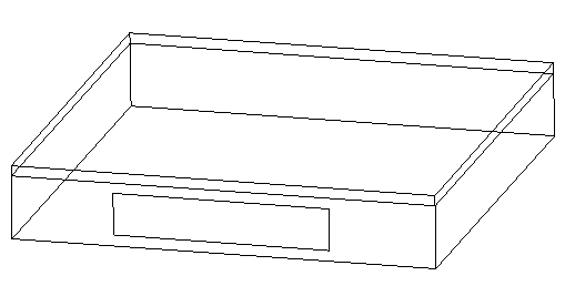
Figure 114. Illustration of Zone Return Plenum
After all the building zone attributes are specified, the AirLoopHVAC:ReturnPlenum object is specified and included as one of the named components in an AirLoopHVAC:ReturnPath.
A unique identifying name identifying the AirLoopHVAC:ReturnPlenum system component.
The zone name specified in the heat balance portion of the input. This piece of input connects the zone return plenum system component to the heat balance data structure.
The name of the zone node. The zone node name connects the heat balance data structure to the system airflow data structure through this node. This node name is defined by the user in the field “Zone Air Node Name” in the ZoneHVAC:EquipmentConnections object for the zone named in the previous field.
The name of the return plenum outlet node. For the zone return plenum there is only one outlet node that can be specified.
The name of a plenum inlet node. There is no limit to the number of inlet nodes, and there may be no duplicate inlet node names. (Note that some EnergyPlus editing tools may allow only 500 inlet node names, but this may be increased by extending the object in the Energy+.idd file.)
And, an IDF example of a zone return plenum component specification:
AirLoopHVAC:ReturnPlenum,
Zone 1a Plenum, ! Name
ZONE 1a, ! Zone Name
Zone 1a Node, ! Zone Node Name
Zone 1a Plenum Outlet Node, ! Outlet Node Name
Zone 1 Outlet Node; ! Inlet 1 Node Name
Below is an example of the AirLoopHVAC:ReturnPath for the simple case shown above.
AirLoopHVAC:ReturnPath,
TermReheatReturnPath, ! Name
Return Air Mixer Outlet, ! Return Air Path Outlet Node Name
Zone Return Plenum, ! Component 1 Object Type
Zone 1a Plenum, ! Component 1 Name
Zone Mixer, ! Component 2 Object Type
Zone Return Air Mixer; ! Component 2 Name
The building shown in the figure below consists of three controlled zones served by an AirLoopHVAC:SupplyPlenum beneath the floor.
Figure 115. Illustration of AirLoopHVAC:SupplyPlenum
The AirLoopHVAC:SupplyPlenum has a heat balance connection and building description, and a system airflow connection which transfers the airflow from the supply plenum zone to the controlled zones in the system simulation. The input described in this section is mainly just for the system airflow connections in the HVAC algorithms. In addition the supply plenum zone must be fully input in the building zone description. The supply plenum zone description needs to contain the wall descriptions, the interzone ceiling and floor, and the ground connection. All the other attributes of a zone that can be specified in the building description can be utilized with a supply plenum zone if necessary, i.e. scheduled loads, windows, etc.
After all the building zone attributes are specified, the AirLoopHVAC:SupplyPlenum object is specified and included as one of the named components in an AirLoopHVAC:SupplyPath.
A unique identifying name identifying the AirLoopHVAC:SupplyPlenum system component.
The zone name specified in the heat balance portion of the input. This piece of input connects the AirLoopHVAC:SupplyPlenum system component to the heat balance data structure.
The name of the zone node. The zone node name connects the heat balance data structure to the system airflow data structure through this node. This node name is defined by the user in the field “Zone Air Node Name” in the ZoneHVAC:EquipmentConnections object for the zone named in the previous field.
The name of the inlet node to the supply plenum. The AirLoopHVAC:SupplyPlenum component can send air to many outlets, but there is only one inlet.
The name of a plenum outlet node. There is no limit to the number of outlet nodes, and there may be no duplicate outlet node names. (Note that some EnergyPlus editing tools may allow only 500 outlet node names, but this may be increased by extending the object in the Energy+.idd file.)
An IDF example of an AirLoopHVAC:SupplyPlenum component specification:
AirLoopHVAC:SupplyPlenum,
Supply Plenum 1, ! Name
SUPPLY PLENUM ZONE, ! Zone Name
Supply Plenum 1 Zone Node, ! Zone Node Name
Zone Equipment Inlet Node, ! Inlet Node Name
Supply Plenum 1 Outlet Node; ! Outlet 1 Node Name
Below is an example of the AirLoopHVAC:SupplyPath for the building shown above.
AirLoopHVAC:SupplyPath,
TermReheatSupplyPath, ! Name
Zone Equipment Inlet Node, ! Supply Air Path Inlet Node Name
AirLoopHVAC:SupplyPlenum, ! Component 1 Object Type
Supply Plenum 1, ! Component 1 Name
AirLoopHVAC:ZoneSplitter, ! Component 2 Object Type
Zone Supply Air Splitter; ! Component 2 Name
The AirLoopHVAC:ZoneSplitter is a component that splits airflow from a single inlet to multiple outlets. This component must be referenced in an AirLoopHVAC:SupplyPath object. The input contains only node connection information.
Unique name for this zone splitter.
The name of the single inlet node going into the splitter.
The name of a splitter outlet node. There is no limit to the number of outlet nodes, and there may be no duplicate outlet node names. (Note that some EnergyPlus editing tools may allow only 500 outlet node names, but this may be increased by extending the object in the Energy+.idd file.)
An example is shown below.
AirLoopHVAC:ZoneSplitter,
Zone Supply Air Splitter, ! Name
Zone Equipment Inlet Node, ! Inlet Node Name
Zone 1 Damper Inlet Node, ! Outlet 1 Node Name
Zone 2 Damper Inlet Node, ! Outlet 2 Node Name
Zone 3 Damper Inlet Node; ! Outlet 3 Node Name
The AirLoopHVAC:ZoneMixer takes the air from multiple inlets and mixes the streams together to be sent out of a single outlet node. This is a simple process of summing flows and averaging the air properties. This compoment may be part of an air loop return path or part of an induction terminal unit. When used as a return air mixer, this component must be listed in an AirLoopHVAC:ReturnPath object, and the inlets may be zone return air nodes or AirLoopHVAC:ReturnPlenum outlet nodes. When used in an induction terminal unit (ref. AirTerminal:SingleDuct:SeriesPIU:Reheat, AirTerminal:SingleDuct:ParallelPIU:Reheat, and AirTerminal:SingleDuct:ConstantVolume:FourPipeInduction), one inlet node is the supply (primary) air inlet from the central air handler, and the second inlet node is the induced (secondary) air inlet. These node names should match equivalent node names in the terminal unit.
Unique name for this zone mixer.
The name of the single outlet node leaving the mixer.
The name of a mixer inlet node. There is no limit to the number of inlet nodes, and there may be no duplicate inlet node names. (Note that some EnergyPlus editing tools may allow only 500 inlet node names, but this may be increased by extending the object in the Energy+.idd file.)
An input example is shown below.
AirLoopHVAC:ZoneMixer,
Zone Return Air Mixer, ! Name
Return Air Mixer Outlet Node, ! Outlet Node Name
Zone 1 Outlet Node, ! Inlet 1 Node Name
Zone 2 Outlet Node, ! Inlet 2 Node Name
Zone 3 Outlet Node; ! Inlet 3 Node Name
The non-zone equipment group consists of plant objects that connect to the demand side of the plant loop but are not associated with a a specific Zone (and do not have their own group). There is currently one non-zone equipment object called LoadProfile:Plant. This object places a scheduled demand load on the plant.
Non-zone equipment allows the option of performing a plant-only EnergyPlus simulation, i.e. without any zones. This can be useful for comparing the performance of various plant configurations or components without the added complexity of a full building description.
The LoadProfile:Plant object is used to simulate a scheduled demand profile. This can be useful when the building loads are already known. Demanded load and flow rate are schedules specified in the object definition. The load profile can specify heating and cooling loads. Cooling loads are entered as negative numbers. The actual load met is dependent on the performance of the supply loop components.
The LoadProfile:Plant object must be connected on the demand side of the plant loop. It should be located on a Branch with its control type set to “Active.” If desired, multiple LoadProfile:Plant objects can be combined in series and/or parallel.
The unique name of the LoadProfile:Plant object.
The name of the inlet node connection to the plant loop.
This node should be on the demand side.
The name of the outlet node connection to the plant loop.
Reference to the schedule object specifying the load profile [W].
The peak demanded water flow rate [m3/s]. This value is multiplied by the flow rate fraction schedule values (below) to determine the actual volumetric flow rate.
Reference to the schedule object specifying the flow rate fraction relative to the value in the field Peak Flow Rate (above).
An example of this object follows.
LoadProfile:Plant,
Load Profile 1, !- Name
Demand Load Profile 1 Inlet Node, !- Inlet Node Name
Demand Load Profile 1 Outlet Node, !- Outlet Node Name
Load Profile 1 Load Schedule, !- Load Schedule Name {W}
0.003, !- Peak Flow Rate {m3/s}
Load Profile 1 Flow Frac Schedule; !- Flow Rate Fraction Schedule Name
The following output variables and meters are reported for the LoadProfile:Plant object:
HVAC,Average,Plant Load Profile Mass Flow Rate [kg/s]
HVAC,Average,Plant Load Profile Heat Transfer Rate [W]
HVAC,Sum,Plant Load Profile Heat Transfer Energy [J]
Zone,Meter,EnergyTransfer:Facility [J]
Zone,Meter,EnergyTransfer:Plant [J]
Zone,Meter,Miscellaneous:EnergyTransfer [J]
The inlet and outlet node temperatures and mass flow rates can be monitored using the system node output variables:
HVAC,Average,System Node Temp [C]
HVAC,Average,System Node MassFlowRate [kg/s]
Solar collectors are thermal devices that convert solar energy into thermal energy by raising the temperature of a circulating heat transfer fluid. The fluid can then be used to heat water for domestic hot water usage or space heating.
In EnergyPlus solar collectors are components that are connected to the plant loop. A solar heating system can be constructed with a combination of solar collectors, pumps, and hot water tanks.
Solar collectors are defined using two objects: SolarCollector:FlatPlate:Water and SolarCollectorPerformance:FlatPlate. The SolarCollector:FlatPlate:Water object describes the plant component connections. The object also references a SolarCollectorPerformance:FlatPlate object which contains the thermal and optical performance test data for a specific make and model of collector. Parameters are defined separately so that these values can be organized into a reference data set and need only be entered once if for an array of the same type of collectors.
The flat-plate solar collector model simulates glazed, unglazed, and tubular (i.e. evacuated tube) collectors. The SolarCollector:FlatPlate:Water object represents a single collector module connected to the plant loop. The thermal and optical properties of the collector module are taken from the referenced SolarCollectorPerformance:FlatPlate object. A surface or shading object defines the collector tilt, azimuth, and gross area. The collector surface participates normally in all shading calculations if the "FullExterior," "FullInteriorAndExterior," “FullExteriorWithReflections “, or “FullInteriorAndExteriorWithReflections” flags are set in the Solar Distribution field of the Building object. Inlet and outlet nodes are specified for plant connections on the demand side of the plant loop.
The unique name of the SolarCollector:FlatPlate:Water object.
Reference name of a SolarCollectorPerformance:FlatPlate object that defines the thermal and optical properties of the collector.
Reference to one of the many different types of surfaces such as the BuildingSurface:Detailed or the Shading:Zone:Detailed objects. The surface named here is used to define the solar collector tilt, azimuth, and gross area.
The name of the inlet node connection to the plant loop.
The name of the outlet node connection to the plant loop.
The maximum flow rate [m3/s] allowed through the collector. This field is optional. If not specified, the collector will allow as much flow as the rest of the plant can deliver.
An example follows.
SolarCollector:FlatPlate:Water,
Collector 1, !- Name
ACR Solar International Fireball 2001, !- Solar Collector Performance Name
Collector Surface, !- Surface Name
Collector Inlet Node, !- Inlet Node Name
Collector Outlet Node, !- Outlet Node Name
0.00005; !- Maximum Flow Rate (m3/s)
The following output variables are reported for the SolarCollector:FlatPlate:Water object:
HVAC,Average,Solar Collector Incident Angle Modifier []
HVAC,Average,Solar Collector Efficiency []
HVAC,Average,Solar Collector Heat Transfer Rate [W]
HVAC,Average,Solar Collector Heat Gain Rate [W]
HVAC,Average,Solar Collector Heat Loss Rate [W]
HVAC,Sum,Solar Collector Heat Transfer Energy [J]
The incident angle modifier is an important intermediate value used in the SRCC calculation of solar collector performance. The value reported here is the combined result for the current time that includes incident angles of beam solar, diffuse solar from sky, and diffuse solar from ground.
The overall collector efficiency. This is the ratio of collected energy and the incident solar energy. The efficiency can be greater than 1 at times when the outdoor air temperature is warm enough.
These are the overall rate (in W) and amount of energy ( in J) transferred to the collector’s circulating fluid. Positive values indicate heating of the fluid while negative values indicate cooling of the fluid.
This is the overall rate of heat addition to the collector’s circulating fluid in Watts. Values are always positive or zero. If the fluid is actually cooled then the value is zero.
This is the overall rate of heat loss from the collector’s circulating fluid in Watts. Values are always positive or zero. If the fluid is actually heated then the value is zero.
In addition, several surface variables are also relevant for the collector’s surface object (BuildingSurface:Detailed or Shading:Zone:Detailed):
Zone,Average,Surface Ext Sunlit Area [m2]
Zone,Average,Surface Ext Sunlit Fraction []
Zone,Average,Surface Ext Solar Incident [W/m2]
Zone,Average,Surface Ext Solar Beam Incident [W/m2]
Zone,Average,Surface Ext Solar Sky Diffuse Incident [W/m2]
Zone,Average,Surface Ext Solar Ground Diffuse Incident [W/m2]
Zone,Average,Surface Ext Solar Beam Cosine Of Incidence Angle []
The temperatures at the inlet and outlet nodes and the collector mass flow rate can be monitored using the system node output variables:
HVAC,Average,System Node Temp[C]
HVAC,Average,System Node MassFlowRate[kg/s]
The SolarCollectorPerformance:FlatPlate object contains the thermal and optical performance parameters for a single collector module. These parameters are based on the testing methodologies described in ASHRAE Standards 93 and 96. The Solar Rating and Certification Corporation (SRCC) applies these standards in their rating procedures of solar collectors. The ratings for commercially available collectors in North America are published in the Directory of SRCC Certified Solar Collector Ratings. The SRCC database has also been converted into an EnergyPlus data set of SolarCollectorPerformance:FlatPlate objects that is included with the program (see SolarCollectors.idf in the DataSets folder).
The coefficients for the energy conversion efficiency and incident angle modifier allow first order (linear) or second order (quadratic) correlations. To use a first order correlation, the second order coefficient must be left blank or set to zero.
In order for the model to work correctly, the test conditions for which the performance coefficients were measured must be specified in the fields: Test Fluid, Test Volumetric Flow Rate, and Test Correlation Type. Currently, only water is allowed as the Test Fluid.
For more detailed information about the performance coefficients, see the EnergyPlus Engineering Reference Document.
The unique name of the SolarCollectorPerformance:FlatPlate object.
The gross area of the collector module [m2]. This value is mainly for reference. The area of the associated collector surface object is used in all calculations.
The fluid that was used in the testing procedure that resulted in the thermal and optical performance coefficients below. Currently only “Water” is allowed. This the fluid during the collector testing, not the fluid used during a particular EnergyPlus run.
The volumetric flow rate during testing [m3/s]. If the value is available as flow rate per unit area, it is recommended to multiply by the Gross Area of the collector module, not the net aperture area.
This field specifies type of temperature used to develop the correlation equations. The testing procedure is based on an experimental correlation using either “Inlet,” “Average,” or “Outlet” temperature. Enter one of these choices. The ASHRAE Standards 93 and 96 always use Inlet temperature.
First coefficient of efficiency equation for energy conversion [dimensionless]. This is the Y-intercept term.
Second coefficient of efficiency equation for energy conversion [W/m2-deltaC]. This is the first-order term.
Third coefficient of efficiency equation for energy conversion [W/m2-deltaC2]. This field is optional. This is the second-order term. If left blank or set to zero, a first-order linear correlation is used.
Second coefficient of the incident angle modifier equation. This the first-order term. (There is no Coefficient 1 of Incident Angle Modifier because that number is always 1.0.)
Third coefficient of the incident angle modifier equation. This is the second-order term. This field is optional. If left blank or set to zero, a first order linear correlation is used.
An example of this object follows.
SolarCollectorPerformance:FlatPlate,
ACR Solar International Fireball 2001, !- Name
1.865, !- Gross Area (m2)
Water, !- Test Fluid
0.0000316, !- Test Flow Rate (m3/s)
Inlet, !- Test Correlation Type (Inlet | Average | Outlet)
0.605, !- Coefficient 1 of Efficiency Equation
-3.837, !- Coefficient 2 of Efficiency Equation
0.00165, !- Coefficient 3 of Efficiency Equation
-0.1944, !- Coefficient 2 of Incident Angle Modifier
-0.0186; !- Coefficient 3 of Incident Angle Modifier
This object does not generate any output; see SolarCollector:FlatPlate:Water Output
This object is used to model hybrid photovoltaic-thermal (PVT) solar collectors that convert incident solar energy into both electricity and useful thermal energy. This object describes the PVT solar collector by referencing other objects that provide more detail or connections to other parts of the EnergyPlus model.
The PVT solar collectors need to be connected to either an HVAC air system or a plant loop for collected thermal energy to be utilized. The input field for the type of thermal working fluid informs the program how the PVT collector is expected to be connected. If the the working fluid is air, then the PVT collectors are modeled as a ventilation air pretreatment component and connected to an outdoor air system. If the working fluid is water, then the PVT collectors are modeled as a hot water solar collector and are connected to a plant loop with a water thermal storage tank.
This field should contain a unique name chosen by the user to identify a specific PVT collector in the building model.
This field is the user-defined name of a surface object (defined elsewhere) to which the PVT module is attached. These can be any type of building surface that is exposed to the exterior environment. The model uses the named surface’s geometry for the PVT solar collector.
This field is the user-defined name of an object (defined elsewhere) that provides the performance details of the PVT module. This should be the name of a SolarCollectorPerformance:PhotovoltaicThermal:Simple object. Multiple different SolarCollector:FlatPlate:PhotovoltaicThermal objects can reference the same object that provides performance details.
This field is the user-defined name of a Generator:Photovoltaic object (defined elsewhere) that will be used to model the solar electric portion of the PVT solar collector. The PVT models make any adjustments needed to model PV performance in the context of the PVT collector.
This field is the user’s choice for the type of fluid used to collect thermal energy. PVT solar collectors can capture thermal energy in either air or water streams. The choices available for this field are “Water” or “Air.” If the choice is “Air” then the PVT collector needs to be connected to an HVAC air system loop. The PVT collector should be situated as the first component on an outdoor air inlet stream. If the choice is “Water” then the PVT collector needs to be connected to a Plant water system loop. The connections are made via node names which are defined in the following fields, depending on the working fluid type.
This field is the name of Plant loop node that serves as the inlet to the PVT collector. This field is only used if the Thermal Working Fluid Type is set to “Plant/Water.”
This field is the name of a plant loop node that seves as the outlet from the PVT collector. This field is only used if the Thermal Working Fluid Type is set to “Plant/Water.”
This field is the name of HVAC air loop node that serves as the inlet to the PVT collector. This field is only used if the Thermal Working Fluid Type is set to “HVAC/Air.”
This field is the name of HVAC air loop node that serves as the outlet from the PVT collector. This field is only used if the Thermal Working Fluid Type is set to “HVAC/Air.”
This field is used to describe the nominal volume flow rate of the thermal working fluid. The units are m3/s. The volume flow rate is autosizable.
An example of this object follows.
SolarCollector:FlatPlate:PhotovoltaicThermal,
PVT: 1_Ceiling , !- Name
1_Ceiling , !- Surface Name
30percentPVThalfArea , !- Photovoltaic-Thermal Model Performance Name
PV:ZN_1_FLR_1_SEC_1_Ceiling , !- Photovoltaic Name
Air , !- Thermal Working Fluid Type
, !- Water Inlet Node Name
, !- Water Outlet Node Name
ZN_1_FLR_1_SEC_1:Sys_OAInlet Node , !- Air Inlet Node Name
PVT:ZN_1_FLR_1_SEC_1_Ceiling Outlet , !- Air Outlet Node Name
Autosize ; !- Design Flow Rate
The output variables that are available for flat plate PVT include the following.
HVAC,Average,Generator Thermal Power Produced [W]
HVAC,Sum,Generator Thermal Energy Produced [J]
HVAC,Average,PVT Bypass Status [ ]
HVAC,Average,PVT Working Fluid Inlet Temperature [C]
HVAC,Average,PVT Working Fluid Outlet Temperature [C]
HVAC,Average,PVT Working Fluid Mass Flow Rate [kg/s]
These outputs are the thermal energy and power produced by the PVT collector. PVT collectors are a type of cogenerator, producing both electrical and thermal power and these variables report the thermal portion in the same manner as other fuel-based cogenerators. The thermal energy is placed on “HeatProduced” meter and is attributed to ‘SolarWater’ or ‘SolarAir’ depending on the type of working fluid. The generator thermal production is also reported at the load center level.
This report variable indicates the status a bypass damper. It is only available for air-based PVT. There are no dimensions and the range is between 0.0 and 1.0. If the value is 0.0, then there is no bypassing and all the working fluid goes through the collector. If the value is 1.0, then there is complete bypassing and all the working fluid goes around the collector. If the value is between 0.0 and 1.0, then the model is effectively mixing bypass and collector streams to target a temperature setpoint placed on the outlet node.
This report is the inlet temperature of the working fluid that enters the PVT collector
This report is the outlet temperature of the working fluid that leaves the PVT collector
This report is the mass flow rate of the working fluid through the PVT collector. This is the overall mass flow rate, portions of the flow may be internally bypassed around the collector itself for control modulation.
This object is used to provide performance details for the simple PVT model. This is a simple user-defined efficiency model. Thermal conversion efficiency is a constant or scheduled value. There are no output variable for this object, reporting is done by the parent PVT object.
This field is the unique name for this object.
This field is the fraction of the surface area that is active. It should be a decimal fraction between 0.0 and 1.0. The area of the PVT’s surface will be multiplied by this fraction to determine the active area of the PVT collector(s).
This field is used to determine how the thermal efficiency is input. There are two choices, “Fixed” or “Scheduled.” If this field is set to Fixed, then a constant value for thermal efficiency will be used (set in next field). If this field is set to Scheduled, then the thermal efficiency values are defined in a schedule.
This field is used to provide a value for the efficiency with which solar energy is collected in the working fluid. This field is only used if the input mode is set to “Fixed” in the previous field. Efficiency is defined as the thermal energy collected divided by the incident solar radiation. The value should be between 0.0 and 1.0. The user should be careful that the thermal efficiency and the electrical efficiency be consistent with each other because the overall efficiency of the PVT collector is the combination of both thermal and electrical.
This field is used for the name of a schedule that provides values for the efficiency with which solar energy is collected in the working fluid. This field is only used if the input mode is set to “Scheduled” in the field above. Efficiency is defined as the thermal energy collected divided by the incident solar radiation. The values in the named schedule should be between 0.0 and 1.0. The user should be careful that the thermal efficiency and the electrical efficiency be consistent with each other because the overall efficiency of the PVT collector is the combination of both thermal and electrical.
This field is used to describe an average value for the total hemispherical emittance of the collector’s front face exposed to the sky. This is used to model cooling applications where the PVT collectors are operated at night to cool the working fluid.
An example input object follows.
SolarCollectorPerformance:PhotovoltaicThermal:Simple,
20percentEffPVhalfArea , !- Name
0.5 , !- Fraction of Surface Area with Active Thermal Collector
Fixed , !- Thermal Conversion Efficiency Input Mode Type
0.2 , !- Value for Thermal Conversion Efficiency if Fixed
, !- Name of Schedule for Thermal Conversion Efficiency
0.84 ; !- Front Surface Emittance
This section provides an overview of how to model solar heating systems. A solar heating system can be constructed using a combination of solar collectors, pumps, water tanks and water heaters. The solar collector must be connected on the demand side of the plant loop. Multiple collector modules can be combined in series and parallel using the normal plant connection rules. The supply side of the plant loop should contain a water heater with the solar collector loop connecting to the Source Side Inlet and Source Side Outlet nodes. As usual, the pump must be the first component on the supply side.
If the solar heating system is for domestic hot water (or service water heating) usage only, the field Use Flow Rate Fraction Schedule Name of the WaterHeater:Mixed object can be used to avoid additional plant connections. If the system has more complicated hot water requirements or if the system is for space heating, the Use Side Inlet and Use Side Outlet nodes must be connected to another plant loop to serve zone and non-zone equipment. (See the WaterHeater:Mixed object documentation for more information.)
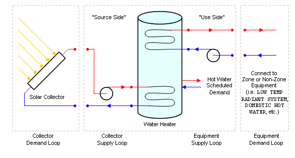
Figure 116. Solar Collector Plant Loop Connection Diagram
NOTE: The EnergyPlus plant simulation requires the pump to be the first component on the supply side. This may be different from the way the solar heating system is actually configured. This should not affect the validity of the simulation results.
In order to realize energy savings with a solar heating system, it is best to use a two-tank system with a storage tank and auxiliary water heater. The storage tank gathers heat directly from the solar collectors and stores it for later use. The storage tank is modeled using a WaterHeater:Mixed object with the Heater Maximum Capacity set to zero. The auxiliary water heater is positioned downstream of the storage tank on the supply side of the main plant loop. The auxiliary water heater, or booster water heater, provides additional heat if the storage tank water is not hot enough. The auxiliary water heater can be modeled as an instantaneous/tankless water heater or as a standard tanked water heater with heating source (see WaterHeater:Mixed).
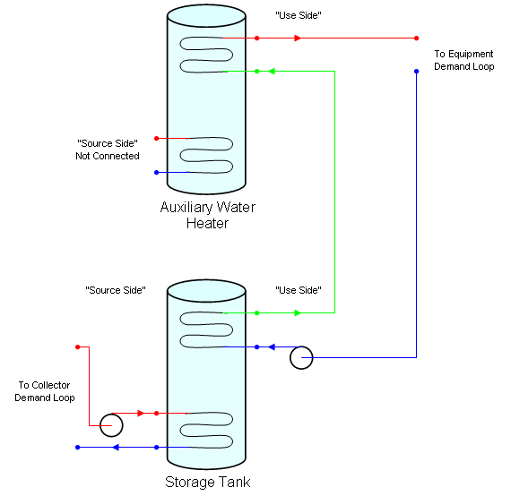
Figure 117. Two-Tank Solar Heating System Connection Diagram
Another strategy to consider for solar heating systems is to allow the storage tank to reach a much higher temperature than necessary for the end use. This allows the tank to store more energy from the solar collectors, when it is available. However, for applications such as domestic hot water, it is undesirable and unsafe to supply excessive hot water temperatures at the point of demand. To take advantage of higher storage temperatures, yet still avoid scalding temperatures at the faucet, the hot water leaving the storage tank can be tempered with cold water using a three-way valve to achieve the target temperature. See the TemperingValve object documentation for more details.
A complete two-tank solar heating system with tempering valve is shown below.
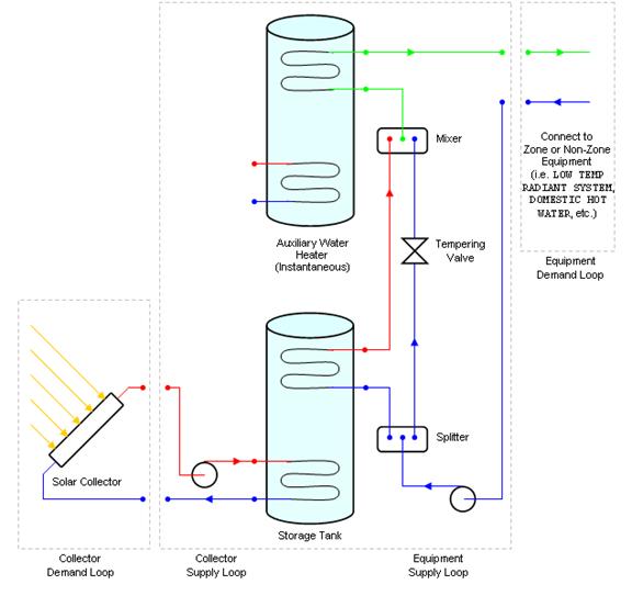
Figure 118. Two-Tank Solar Heating System with Tempering Valve
There are several options for controlling a solar heating system in EnergyPlus. Since the solar collectors request a constant flow demand based on their Maximum Flow Rate, the limiting factor is actually the flow rate determined by the loop pump. Therefore the entire system can be controlled using the Pump Flow Rate Schedule of the pump. If the schedule is omitted, the pump and system will run all the time (without any other controls specified). This is usually not the best way to operate a solar heating system.
To better control the collector loop, a differential thermostat can be used to compare the temperature in the water heater to the temperature in the collector so that the pump is only turned on when there is a useful heat gain. The differential thermostat is simulated using the AvailabilityManager:DifferentialThermostat object. For a typical system, the Hot Node Name field refers to an outlet node of one of the collector modules. The Cold Node Name field refers to the Source Side Outlet node, i.e. the cold storage water leaving the water heater. The fields Temperature Difference On Limit and Temperature Difference Off Limit are usually 8 –12 C and 1 – 3 C respectively. If the two temperature differences are too close, it is possible for the system to turn on and off rapidly without much useful heat gain. This can also occur if the flow rate through the collector is too high. Without flow the fluid in the collector heats up more quickly; when high flow is turned on, all of the hot fluid is removed and the temperature drops, forcing the system off again.
Another control method is to use a photovoltaic panel to power the pump. The system begins pumping when there is enough solar radiation to operate the pump. This is not yet implemented in EnergyPlus.
In climates with a cold season, the solar heating system must be designed to avoid the risk of fluid freezing in the solar collector or exposed pipes and causing damage. This is not a problem if air is the heat transfer fluid. With water, however, there are several strategies that can minimize the risk.
Seasonal schedule. The simplest strategy is to not use the system during the cold season. This is a hassle because it requires the collector to be manually drained of all fluid. The benefits of the solar heating system are also lost during this time. This can be simulated in EnergyPlus with the appropriate pump schedule for the collector system.
Antifreeze. The freezing point of the liquid is decreased by adding antifreeze to the water or using a different heat transfer liquid with a lower freezing point. This cannot yet be simulated in EnergyPlus because only pure water is currently allowed in plant loops.
Drain-back system. This strategy automatically empties the collector when the pump is not running. This scenario is modeled by default in EnergyPlus, although the extra pump energy required to start the system is not taken into account.
Recirculation system. This strategy automatically recirculates warm liquid from the storage tank back through the collector to maintain the system above the freezing point. There are system losses using this method. This can be simulated in EnergyPlus by using AvailabilityManager:LowTemperatureTurnOn to force the system to turn on when the outdoor air temperature or collector outlet temperature falls below a specified minimum.
In addition to freeze prevention, it is also necessary to prevent the system from becoming too hot. This is usually a safety issue for the water heater. For this case it is important to have a high temperature cutoff to stop the pump before damaging the water heater. This is accomplished with a AvailabilityManager:HighTemperatureTurnOff.
To use the availability managers for the control cases described above, a AvailabilityManagerAssignmentList must be defined and referenced in the PlantLoop object of the collector loop. An example of a differential thermostat, recirculation for freeze prevention, and high temperature cutoff is shown below:
AvailabilityManagerAssignmentList,
Collector Loop Availability Manager List, !- Name
AvailabilityManager:HighTemperatureTurnOff, !- Availability Manager 1 Object Type
High Temperature Turn Off Availability Manager, !- Availability Manager 1 Name
AvailabilityManager:HighTemperatureTurnOn, !- Availability Manager 2 Object Type
Low Temperature Turn On Availability Manager, !- Availability Manager 2 Name
AvailabilityManager:DifferentialThermostat, !- Availability Manager 3 Object Type
Differential Thermostat Availability Manager; !- Availability Manager 3 Name
AvailabilityManager:HighTemperatureTurnOff, ! For water heater safety
High Temperature Turn Off Availability Manager, !- Name
Water Heater Use Outlet Node, !- Sensor Node Name
60.0; !- Temperature (C)
AvailabilityManager:HighTemperatureTurnOn, ! For freeze prevention by recirculation
Low Temperature Turn On Availability Manager, !- Name
Collector Outlet Node, !- Sensor Node Name
0.0; !- Temperature (C)
AvailabilityManager:DifferentialThermostat, ! For useful heat gain from collector to tank
Differential Thermostat Availability Manager, !- Name
Collector Outlet Node, !- Hot Node Name
Water Heater Source Outlet Node, !- Cold Node Name
10.0, !- Temperature Difference On Limit (delta C)
2.0; !- Temperature Difference Off Limit (delta C)
The AvailabilityManager:DifferentialThermostat object must always be the last manager in the availability manager list. See the AvailabilityManagerAssignmentList object documentation for more information.
This object is used to model unglazed transpired solar collectors (UTSC) used to condition outdoor air. These collectors are generally used to heat air drawn through perforated absorbers that are heated by the sun and also recover heat conducted out through the underlying wall. The SolarCollector:UnglazedTranspired object represents a single collector attached to one or more BuildingSurface:Detailed objects and to one or more outdoor air systems. Therefore the transpired collector is part of both the thermal envelope and the HVAC system. An example file is provided called TranspiredCollectors.idf.
The area and orientation of the collector is obtained from BuildingSurface:Detailed objects, which are referenced by name. Although the collector surface itself is slightly detached from the underlying building wall (or roof), no additional surface object is needed to represent the collector itself. When modeling transpired collectors, it is important to consider the size of the collector when developing the building model’s BuildingSurface:Detailed objects because the underlying surfaces must match the collector. For example, if the collector covers only part of the wall, then that wall should be split into separate surfaces where one matches the size of the collector. A single collector can be associated with as many BuildingSurface:Detailed objects as desired (although if you need to use more than 10 surfaces, then the IDD will need to be extended). The collector can be arranged at any tilt angle by describing the surfaces appropriately. The surfaces need not be contiguous nor have the same orientation, but the program will issue warnings if surfaces have widely ranging tilts and azimuths.
The collector conditions outdoor air and is connected to the outdoor air system using the usual method of specifying node names. Using the UTSC model requires specifying a relatively complete HVAC air system that includes an outdoor air path. This will typically require using a set of objects that, at a minimum, will include: AirLoopHVAC:ControllerList, AirLoopHVAC:OutdoorAirSystem:EquipmentList, AirLoopHVAC:OutdoorAirSystem, OutdoorAir:NodeList, OutdoorAir:Mixer, SetpointManager:MixedAir, and Controller:OutdoorAir. A single UTSC can serve more than one outdoor air system but requires also using a separate object, called SolarCollector:UnglazedTranspired:MultiSystem to specify node connections.
Controls for the UTSC involve setting the rate of air flow and the status of a bypass damper. If the bypass damper is open, then all the ventilation air goes straight into the outdoor air mixer; if it closed, then all the air first passes through the UTSC. The bypass damper is modeled as completely open or completely closed. The UTSC bypass damper control is determined by an availability manager, the airflow set by the outdoor air mixer controls, and thermostatic type controls that decide if heating is useful. An availability schedule is used to bypass the collector for certain times of the year, eg. summer cooling season. The air flow rates are set by controls associated with the outdoor air mixer (see SetpointManager:MixedAir, and Controller:OutdoorAir). Thermostatic type control decides if the collector will provide useful heating based on either of two types of setpoints. The first type of temperature setpoint is managed by SetpointManager:MixedAir, where the UTSC model looks at a control node, usually the mixed air node. The second type is an extra setpoint especially for free heating that is managed within this object where the UTSC model looks at the zone air node.
This field contains a unique name for the unglazed transpired solar collector.
This field contains the name of a SurfaceProperty:OtherSideConditionsModel object declared elsewhere in the input file. This will connect the collector to the exterior boundary conditions for the underlying heat transfer surface.
This field contains the name of a schedule that determines whether or not the UTSC is available. When the schedule value is zero, the UTSC is always bypassed. When the schedule value is greater than zero, the UTSC is available and will be used when other conditions are met, such as outdoor air requested by mixer and preheating has been determined to be beneficial based on thermostatic control.
This field contains the name of an air node that provides air into the UTSC. This node name should also be assigned to be an outdoor air node using the OutdoorAir:NodeList or OutdoorAir:Node objects. This node should also be named as the actuated node in a Controller:OutdoorAir object. If the UTSC is connected to more than one air system, then this field can be left blank and the SolarCollector:UnglazedTranspired:MultiSystem object should be used to define the nodes.
This field contains the name of an air node that is the outlet of the UTSC. This node name will typically be the inlet to the OutdoorAir:Mixer (if there is no other equipment on the outdoor air path). If the UTSC is connected to more than one air system, then this field can be left blank and the SolarCollector:UnglazedTranspired:MultiSystem object should be used to define the nodes.
This field contains the name of an air node that has a setpoint manager controlling its temperature setpoint. This node name will typically be named as the control node in a a Controller:OutdoorAir object. If the UTSC is connected to more than one air system, then this field can be left blank and the SolarCollector:UnglazedTranspired:MultiSystem object should be used to define the nodes.
This field contains the name of an air node for a thermal zone that is ultimately connected to the air system. This node is used with the setpoint schedule, defined in the following field, to provide an added layer of thermostatic control for the UTSC without affecting the control of auxiliary heating. If there is a single air system that is connected to more than one zone, then a single zone should be selected based on where the thermostat might be located. If the UTSC is connected to more than one air system, then this field can be left blank and the SolarCollector:UnglazedTranspired:MultiSystem object should be used to define the nodes.
This field contains the name of a temperature schedule defined elsewhere in the input file. This schedule should define temperatures desired in the zone, but not necessarily required. This secondary setpoint schedule is used to allow the UTSC to operate as if it has its own thermostat that is separate from the primary control mechanism. When the UTSC is used with auxiliary heating, the usual setpoint managers and temperature controllers will determine how the auxiliary heaters are controlled. This allows using a higher zone air temperature setpoint for controlling UTSC bypass than for the auxiliary heating system.
This field is used to enter the effective diameter of the perforations in the collector surface. The diameter should be entered in meters. For perforations other than round, use an equivalent diameter for a round hole that would have the same area.
This field is used to enter the pitch, or average, shortest distance between perforations.
This field is used to enter the thermal emissivity of the collector. This surface property is for longwave infrared radiation. The property is used for both sides of collector. Most painted materials have an emissivity of 0.9.
This field is used to enter the solar absorbtivity of the collector. This surface property is for shortwave, solar radiation. The property is used for the front side of the collector that faces the environment. Darker colors have a higher absorbtivity. While black is the highest performance, other colors might be used to match the color scheme of the rest of the facade. The following table provides sample solar absorbtivities for different colors (source: Conserval Engineering Inc., Toronto, Ontario, Canada).
|
Color Name of Kynar®[8] Paint |
Solar Absorptivity |
|
Black |
0.94 |
|
Classic Bronze |
0.91 |
|
Chocolate Brown |
0.90 |
|
Hartford Green |
0.90 |
|
Med. Bronze |
0.89 |
|
Boysenberry |
0.86 |
|
Rocky Grey |
0.85 |
|
Regal Blue |
0.85 |
|
Forest Green |
0.84 |
|
Hemlock Green |
0.82 |
|
Slate Blue |
0.80 |
|
Redwood |
0.79 |
|
Teal |
0.79 |
|
Slate Grey |
0.79 |
|
Patina Green |
0.77 |
|
Mint Green |
0.71 |
|
Dove Grey |
0.69 |
|
Mission Red |
0.69 |
|
Sierra Tan |
0.65 |
|
Brite Red |
0.59 |
|
Rawhide |
0.57 |
|
Sandstone |
0.54 |
|
Silversmith |
0.53 |
|
Coppertone |
0.51 |
|
Concord Cream |
0.45 |
|
Ascot White |
0.40 |
|
Bone White |
0.30 |
This field is used to enter a nominal height for the collector. This value is used in the program to determine a length scale in the vertical direction for the buoyancy-driven portion of natural ventilation that occurs when the collector is inactive. (Note that most of the geometry information is obtained from the underlying surfaces.) The value entered here is adjusted inside the program to account for tilt of the collector. While the value here would generally correspond to the actual distance/height, its value is not critical and it can be used to adjust modeling the air exchange rates in passive mode. If the collector is horizontal, then the length scale is obtained from the following field.
This field is used to enter a nominal gap thickness for the collector. This distance value is only used when the collector is near horizontal to determine a length scale in the vertical direction for buoyancy calculations. For example, if the collector is mounted on a flat roof, its tilt-adjusted height is zero and the program will use this gap thickness as a length scale rather than the height from the previous field.
This field is used to enter the nominal cross sectional area of the gap behind the collector. This area is used to determine a velocity scale for surface convection heat transfer correlations when the collector is active. This value is generally the average gap thickness times the average width of the collector.
This field is used to describe the pattern of perforations in the collector surface. There are currently two choices available: Square and Triangle. Note that the hole layout pattern should be consistent with how the value for pitch was determined.
This field is used to select which correlation is used to model heat transfer from the collector surface to the incoming air when the collector is active. There are two choices available: Kutscher1994, and VanDeckerHollandsBrunger2001. See the Engineering Reference for details and references.
This field is used to enter a factor that accounts for the extra surface area resulting from corrugations in the collector surface. Corrugations help stiffen the collector. The projected surface area is obtained by the program from the (flat) underlying surfaces. If the collector is flat then this ratio is 1.0. If the collector is corrugated, then this ratio will be greater than one. A typical value might be 1.165.
This field is used to describe the relative roughness of the collector material. This field is similar to one in the Materialobject. This parameter only influences the convection coefficients, more specifically the outside convection coefficient. A special keyword is expected in this field with the options being “VeryRough”, “Rough”, “MediumRough”, “MediumSmooth”, “Smooth”, and “VerySmooth” in order of roughest to smoothest options.
This field is used to enter the thickness of the collector material. This value is only needed for the Van Decker Hollands Brunger 2001 correlation. The material thickness should be entered in meters.
This field is used to enter a value for the coefficient used to determine natural air exchanges from wind, or Cv. When the collector is inactive, wind will cause exterior air to move in and out of the collector. Cv is an arbitrary coefficient used to model the effectiveness of openings and depends on opening geometry and the orientation with respect to the wind. Cv should probably be in the range 0.25 to 0.65. Increasing Cv will increase the amount of natural ventilation.
This field is used to enter a value for the coefficient used to determine natural air exchanges from buoyancy, or Cd. When the collector is inactive, stack or buoyancy effects will cause exterior air to move in and out of the collector. Cd is an arbitrary discharge coefficient that depends on the geometry of the opening. Cd should probably be in the range 0.4 to 1.0. Increasing Cd will increase the amount of natural ventilation.
The remaining fields are used to name the BuildingSurface:Detailed objects that are associated with the UTSC. These are the underlying heat transfer surfaces and are defined elsewhere in the input file. These other surfaces should all specify OtherSideConditionsModel as their exterior environment. The input object can currently accommodate up to ten surfaces, but it is extensible.
An example of this object follows.
SolarCollector:UnglazedTranspired,
Shop OA UTSC ZN11, ! Name
UTSC OSCM ZN11, ! Boundary Conditions Model Name
HeatingAvailSched , ! Availability Schedule Name
Outside Air Inlet Node ZN11 , ! Inlet Node Name
UTSC Outlet Node ZN11 , ! Outlet Node Name
Mixed Air Node ZN11 , ! Setpoint Node Name
ZN11 Node, ! Zone Node Name
ShopFreeHeatingSetpoints, ! Free Heating Setpoint Schedule Name
0.0016, ! Diameter of Perforations in Collector
0.01689, ! Distance Between Perforations in Collector
0.9, ! Thermal Emissivity of Collector Surface
0.9, ! Solar Absorbtivity of Collector Surface
4.0, ! Effective Overall Height of Collector
0.1, ! Effective Gap Thickness of Plenum Behind Collector
2.0, ! Effective Cross Section Area of Plenum Behind Collector
Triangle, ! Hole Layout Pattern for Pitch
Kutscher1994, ! Heat Exchange Effectiveness Correlation
1.165, ! Ratio of Actual Collector Surface Area to Projected Surface Area
MediumRough , ! Roughness of Collector
0.00086, ! Collector Thickness
0.25, ! Effectiveness for Perforations with Respect to Wind
0.5, ! Discharge Coefficient for Openings with Respect to Buoyancy Driven Flow
ZN11_Shop_1:ExtWall:South; ! Surface 1 Name
In addition to related output that can be obtained for air nodes and surfaces, these outputs are available for UTSC systems:
HVAC,Average,UTSC Heat Exchanger Effectiveness []
HVAC,Average,UTSC Leaving Air Drybulb from Collector [C]
HVAC,Average,UTSC Average Suction Face Velocity [m/s]
HVAC,Average,UTSC Collector Temperature [C]
HVAC,Average,UTSC Plenum Drybulb Temperature [C]
HVAC,Average,UTSC Sensible Heating Rate [W]
Zone,Meter,SolarAir:Facility [J]
Zone,Meter,SolarAir:HVAC [J]
Zone,Meter,HeatProduced:SolarAir [J]
HVAC,Sum,UTSC Sensible Heating Energy [J]
HVAC,Average,UTSC Air Changes per Hour Passive [ACH]
HVAC,Average,UTSC Total Natural Vent Mass Flow [kg/s]
HVAC,Average,UTSC Total Natural Vent Mass Flow from Wind [kg/s]
HVAC,Average,UTSC Total Natural Vent Mass Flow from Bouyancy [kg/s]
HVAC,Average,UTSC Incident Solar Radiation [W/m2]
HVAC,Average,UTSC Overall Efficiency []
HVAC,Average,UTSC Collector Efficiency []
The results from UTSC correlations defined by ![]() .
.
The temperature of air entering the plenum after being heated by the collector.
The bulk velocity of air approaching the collector.
The surface temperature of the collector itself.
The temperature of air inside, and leaving, the plenum behind the collector.
The overall rate at which heat is being added to the outdoor air stream.
A meter that includes the heating energy provided by the UTSC.
A meter that includes the heating energy provided by the UTSC.
A meter that includes the heating energy provided by the UTSC.
The overall sum of energy added to the outdoor air stream.
The rate of natural ventilation air exchange between the plenum and ambient when the collector is inactive in Air Changes per Hour.
The mass flow rate of natural ventilation air exchange between the plenum and ambient when the collector is inactive.
The part of mass flow rate of natural ventilation air exchange between the plenum and ambient when the collector is inactive due to wind-driven forces.
The part of mass flow rate of natural ventilation air exchange between the plenum and ambient when the collector is inactive due to bouyancy-driven forces.
The intensity of solar radiation incident on the UTSC collector from all sources.
The efficiency of the UTSC system including collected solar energy and heat recovered from the underlying surface.
The efficiency of the UTSC solar collector.
This object is used to model unglazed transpired solar collectors (UTSC) that are connected to multiple outdoor air systems. This object supplements the SolarCollector:UnglazedTranspired object and is only necessary if more than one air system is connected to a single transpired collector. After the name field, there are sets of four node names used to define the connections of each air system. Each set contains node names for inlet, outlet, control, and zone. If more than five air systems are needed, this object is extensible.
This field is used to identify the name of the SolarCollector:UnglazedTranspired object that needs to be connected to more than one air system. This field must match the name.
The following four fields form a repeating set of four fields. One set is used for each outdoor air system that is connected to the collector.
This field contains the name of an air node that provides air into the UTSC. This node name should also be assigned to be an outdoor air node using the OutdoorAir:NodeList and OutdoorAir:Node objects. This node is also be named as the actuator node in a Controller:OutdoorAir object.
This field contains the name of an air node that is the outlet of the UTSC. This node name will typically be the Outdoor Air Stream Node Name in the OutdoorAir:Mixer (if there is no other equipment on the outdoor air path).
This field contains the name of an air node that has a setpoint manager controlling its temperature setpoint. This node name will typically be named as the mixed air node in a Controller:OutdoorAir object.
This field contains the name of an air node for a thermal zone that is ultimately connected to the air system. This node is used with the setpoint schedule, defined in the following field, to provide an added layer of thermostatic control for the UTSC without affecting the control of auxiliary heating. If there is a single air system that is connected to more than one zone, then a single zone should be selected based on where the thermostat might be located.
An example of this object follows.
SolarCollector:UnglazedTranspired:Multisystem,
OFFICE MultiSystem OA UTSC , ! Solar Collector Name
Outside Air Inlet Node ZN1, ! Outdoor Air System 1 Collector Inlet Node
UTSC Outlet Node ZN1, ! Outdoor Air System 1 Collector Outlet Node
Mixed Air Node ZN1, ! Outdoor Air System 1 Mixed Air Node
ZN1 Node, ! Outdoor Air System 1 Zone Node
Outside Air Inlet Node ZN2, ! Outdoor Air System 2 Collector Inlet Node
UTSC Outlet Node ZN2, ! Outdoor Air System 2 Collector Outlet Node
Mixed Air Node ZN2, ! Outdoor Air System 2 Mixed Air Node
ZN2 Node, ! Outdoor Air System 2 Zone Node
Outside Air Inlet Node ZN3, ! Outdoor Air System 3 Collector Inlet Node
UTSC Outlet Node ZN3, ! Outdoor Air System 3 Collector Outlet Node
Mixed Air Node ZN3, ! Outdoor Air System 3 Mixed Air Node
ZN3 Node, ! Outdoor Air System 3 Zone Node
Outside Air Inlet Node ZN4, ! Outdoor Air System 4 Collector Inlet Node
UTSC Outlet Node ZN4, ! Outdoor Air System 4 Collector Outlet Node
Mixed Air Node ZN4, ! Outdoor Air System 4 Mixed Air Node
ZN4 Node, ! Outdoor Air System 4 Zone Node
Outside Air Inlet Node ZN5, ! Outdoor Air System 5 Collector Inlet Node
UTSC Outlet Node ZN5, ! Outdoor Air System 5 Collector Outlet Node
Mixed Air Node ZN5, ! Outdoor Air System 5 Mixed Air Node
ZN5 Node; ! Outdoor Air System 5 Zone Node
EnergyPlus plant and condenser loops need pump components to drive liquid flow around the loop. There are various types of pump models available.
Pumps are needed in both plant and condenser loops. The syntax for a variable speed pump is given below.
This alpha field contains the identifying a unique name for the pump.
This alpha field contains the identifying name for the pump inlet node.
This alpha field contains the identifying name for the pump outlet node.
This numeric field contains the pump’s rated volumetric flow rate in cubic meters per second.
This numeric field contains the pump’s rated head pressure in Pascals.
This numeric field contains the pump’s rated power consumption in Watts. If the user is performing a pressure simulation on the loop in which this pump is found, this value would only be used to estimate pump efficiency. During reported calculations, the pump would use the loop pressure drop and current flow conditions along with efficiency to calculate pump power dynamically.
This numeric field contains the pump’s efficiency in decimal form (0 = 0%, 1 = 100%).
This numeric field contains the pump’s fraction of power loss to the fluid.
This numeric field contains the first coefficient in the part load ratio curve. The fraction of full load power is determined by the cubic equation:
![]()
where C1,C2,C3,and C4 are Coefficients 1 – 4 (below) and PLR is the Part Load Ratio.
This numeric field contains the second coefficient in the part load ratio curve.
This numeric field contains the third coefficient in the part load ratio curve.
This numeric field contains the fourth coefficient in the part load ratio curve.
This field contains the minimum volumetric flow rate while operating in variable flow capacity rate in cubic meters per second.
This is a choice field of Continuous or Intermittent. A variable speed pump is defined with maximum and minimum flow rates that are the physical limits of the device. If there is no load on the loop and the pump is operating intermittently, then the pump can shutdown. For any other condition such as the loop having a load and the pump is operating intermittently or the pump is continuously operating (regardless of the loading condition), the pump will operate and select a flow somewhere between the minimum and maximum limits. In these cases where the pump is running, it will try to meet the flow request made by demand side components. Applicable availability managers (ref. AvailabilityManagerAssignmentList) may override this control by forcing the pump to be on or off.
The schedule values modify the value for Rated Flow Rate of the pump on a time basis. The default is that the pump is ON and runs according to its other operational requirements specified above. This schedule is for special, not typical pump operations.
This references a pump curve to be used during pump flow-loop head resolution. This is only applicable for loop simulations which include pressure components on at least a single branch. More information regarding pressure system simulation is available in the engineering reference.
For pressure simulation cases, this is the impeller diameter used during calculations which is used in non-dimensionalizing the pump curve described in the previous field. The units of this value are meters.
This string defines which type of VFD control type to perform. PressureSetPointControl is a realistic approach which requires inputs of pressure range schedules to control the pump rpm to maintain a certain pressure drop (head). ManualControl is an idealized control strategy in which the pump RPM is maintained at a scheduled value throughout the simulation, abiding by other flow restrictions in the loop.
For VFD Control Type = ManualControl, this defines the pump RPM schedule to use during the simulation. For VFD Control Type = PressureSetPointControl, this field is not interpreted. The value of the schedule is RPM.
For VFD Control Type = PressureSetPointControl, this field defines the minimum pressure range setpoint value, or the lower bound of pressure drop (head) to use when determining the required pump speed. For VFD Control Type = ManualControl, this field is not interpreted. The value of the schedule is Pascals.
For VFD Control Type = PressureSetPointControl, this field defines the maximum pressure range setpoint value, or the upper bound of pressure drop (head) to use when determining the required pump speed. For VFD Control Type = ManualControl, this field is not interpreted. The value of the schedule is Pascals.
For VFD Control Type = PressureSetPointControl, this field defines the minimum allowable RPM, or the lower bound of pump speed to use when determining the required pump speed. For VFD Control Type = ManualControl, this field is not interpreted. The value of the schedule is RPM.
For VFD Control Type = PressureSetPointControl, this field defines the maximum allowable RPM, or the upper bound of pump speed to use when determining the required pump speed. For VFD Control Type = ManualControl, this field is not interpreted. The value of the schedule is RPM.
Examples of this object in the IDF follow.
Pump:VariableSpeed,
HW Circ Pump, !- Name
HW Supply Inlet Node, !- Inlet Node Name
HW Pump Outlet Node, !- Outlet Node Name
autosize, !- Rated Flow Rate {m3/s}
179352, !- Rated Pump Head {Pa}
autosize, !- Rated Power Consumption {W}
0.9, !- Motor Efficiency
0.0, !- Fraction of Motor Inefficiencies to Fluid Stream
0, !- Coefficient 1 of the Part Load Performance Curve
1, !- Coefficient 2 of the Part Load Performance Curve
0, !- Coefficient 3 of the Part Load Performance Curve
0, !- Coefficient 4 of the Part Load Performance Curve
0, !- Minimum Flow Rate {m3/s}
Intermittent; !- Pump Control Type
Pump:VariableSpeed,
Circ Pump, !- Name
CW Supply Inlet Node, !- Inlet Node Name
CW Pump Outlet Node, !- Outlet Node Name
.0011, !- Rated Flow Rate {m3/s}
300000, !- Rated Pump Head {Pa}
500, !- Rated Power Consumption {W}
.87, !- Motor Efficiency
0.0, !- Fraction of Motor Inefficiencies to Fluid Stream
0, !- Coefficient 1 of the Part Load Performance Curve
1, !- Coefficient 2 of the Part Load Performance Curve
0, !- Coefficient 3 of the Part Load Performance Curve
0, !- Coefficient 4 of the Part Load Performance Curve
0, !- Minimum Flow Rate {m3/s}
Intermittent; !- Pump Control Type
HVAC,Average,Pump Electric Power [W]
HVAC,Sum,Pump Electric Consumption [J]
HVAC,Average,Pump Shaft Power [W]
HVAC,Average,Pump Heat To Fluid [W]
HVAC,Sum,Pump Heat To Fluid Energy [J]
HVAC,Average,Pump Outlet Temp [C]
HVAC,Average,Pump Mass Flow Rate [kg/s]
These outputs are the electric power input to the pump motor. Consumption is metered on Pumps:Electricity, Electricity:Plant, and Electricity:Facility.
This is the shaft power delivered from the motor to the pump.
These outputs are the energy added to the fluid as heat. For the current algorithm, this is equal to Pump Shaft Power, because the loops are closed and all energy added to the fluid will ultimately become heat due to friction.
These outputs are the water outlet temperature and mass flow rate.
Pumps may be found in both plant and condenser loops. The syntax for a constant speed pump is given below.
This alpha field contains the identifying name for the pump.
This alpha field contains the identifying name for the pump inlet node.
This alpha field contains the identifying name for the pump outlet node.
This numeric field contains the pump’s rated volumetric flow rate in cubic meters per second.
This numeric field contains the pump’s rated head pressure in Pascals.
This numeric field contains the pump’s rated power consumption in Watts. If the user is performing a pressure simulation on the loop in which this pump is found, this value would only be used to estimate pump efficiency. During reported calculations, the pump would use the loop pressure drop and current flow conditions along with efficiency to calculate pump power dynamically.
This numeric field contains the pump’s efficiency in decimal form (0 = 0%, 1 = 100%).
This numeric field contains the pump’s fraction of power loss to the fluid.
This is a choice field of Continuous or Intermittent. The operation of a constant speed pump is fairly straightforward. If the user designates a constant speed pump that is operating continuously, the pump will run regardless of whether or not there is a load. This may have the net effect of adding heat to the loop if no equipment is turned on. If the pump is constant speed and operates intermittently, the pump will run at its capacity if a load is sensed and will shut off if there is no load on the loop. Applicable availability managers (ref. AvailabilityManagerAssignmentList) may override this control by forcing the pump to be on or off.
The schedule values modify the Rated Flow Rate of the pump on a time basis. The default is that the pump is ON and runs according to its other operational requirements specified above. This schedule is for special, not typical pump operations.
This field is only used if the user is performing a pressure-based simulation in the plantloop of the “LoopFlowCorrection” type (see PlantLoop section for how to enable this).
This field references a separate pressure head curve that the user has input separately in the input file. The pressure curve represents a non-dimensional regression of pressure-flow rate data. The equation should be of the following form:
![]()
In this equation, the two dimensionless parameters, X and X are defined in terms of physical pump and flow parameters as:
![]()
![]()
Where “Delta P” is the pressure drop, mdot is the fluid mass flow rate, rho is a representative fluid density, N is the rotational speed of the pump, and D is the pump impeller diameter.
Since the user may not need a full fourth order expansion of this, the user may use linear (first order), quadratic (second order), cubic (third order), or full quartic (fourth order). These are available in the objects Curve:Linear, Curve:Quadratic, Curve:Cubic, Curve:Quartic.
Once this curve is input properly (along with the following two fields), the pump will respond to the plant loop pressure drop when resolving the flow rate. Note that this simulation method will likely result in a plant loop that does not exactly hit the setpoint as the current simulation method does. This is due to the loop flow rate now being “pressure-based” and not “decision-based”.
This field is only used if the user is performing a pressure-based simulation in the plantloop of the “LoopFlowCorrection” type (see PlantLoop section for how to enable this).
To “re-dimensionalize” the dimensionless pump curve, the impeller diameter must be known. This value is entered in meters.
This field is only used if the user is performing a pressure-based simulation in the plantloop of the “LoopFlowCorrection” type (see PlantLoop section for how to enable this).
To “re-dimensionalize” the dimensionless pump curve, the rotational speed must be known. This value is entered in RPM (revolutions per minute).
An example of this object follows.
Pump:ConstantSpeed,
Circ Pump, !- Name
CW Supply Inlet Node, !- Inlet Node Name
PumpChiller Node, !- Outlet Node Name
0.0011, !- Rated Flow Rate
300000, !- Rated Pump Head
700, !- Rated Power Consumption
0.87, !- Motor Efficiency
0.0, !- Fraction of Motor Inefficiencies to Fluid Stream
Intermittent; !- Pump Control Type
HVAC,Average,Pump Electric Power [W]
HVAC,Sum,Pump Electric Consumption [J]
HVAC,Average,Pump Shaft Power [W]
HVAC,Average,Pump Heat To Fluid [W]
HVAC,Sum,Pump Heat To Fluid Energy [J]
HVAC,Average,Pump Outlet Temp [C]
HVAC,Average,Pump Mass Flow Rate [kg/s]
These outputs are the electric power input to the pump motor. Consumption is metered on Pumps:Electricity, Electricity:Plant, and Electricity:Facility.
This is the shaft power delivered from the motor to the pump.
These outputs are the energy added to the fluid as heat. For the current algorithm, this is equal to Pump Shaft Power, because the loops are closed and all energy added to the fluid will ultimately become heat due to friction.
These outputs are the water outlet temperature and mass flow rate.
The Pump:VariableSpeed:Condensate object can only be used in steam system simulation for the condensate side of the loop. This is a variable speed pump, which pumps the condensate back to the steam boiler. The syntax for condensate pump is given below.
This alpha field contains the identifying unique name for the pump.
This alpha field contains the identifying name for the pump inlet node.
This alpha field contains the identifying name for the pump outlet node.
This numeric field contains the pump’s rated volumetric flow rate in cubic meters per second.
This numeric field contains the pump’s rated head in Pascals.
This numeric field contains the pump’s rated power consumption in Watts. If the user is performing a pressure simulation on the loop in which this pump is found, this value would only be used to estimate pump efficiency. During reported calculations, the pump would use the loop pressure drop and current flow conditions along with efficiency to calculate pump power dynamically.
This numeric field contains the pump’s efficiency in decimal form (0 = 0%, 1 = 100%).
This numeric field contains the pump’s fraction of power loss to the fluid.
This numeric field contains the first coefficient in the part load ratio curve. The fraction of full load power is determined by the cubic equation:
![]()
where C1,C2,C3,and C4 are Coefficients 1 – 4 (below) and PLR is the Part Load Ratio.
This numeric field contains the second coefficient in the part load ratio curve.
This numeric field contains the third coefficient in the part load ratio curve.
This numeric field contains the fourth coefficient in the part load ratio curve.
The schedule values modify the Rated Flow Rate of the pump on a time basis the default is that the pump is ON and runs according to its other operational requirements specified above. The schedule is for special, not typical pump operations.
Examples of this object in the IDF follow.
Pump:VariableSpeed:Condensate,
Steam Boiler Plant Steam Circ Pump, !- Name
Steam Boiler Plant Steam Supply Inlet Node, !- Inlet Node Name
Steam Boiler Plant Steam Pump Outlet Node, !- Outlet Node Name
0.36, !- Rated Flow Rate {m3/s}
179352, !- Rated Pump Head {Pa}
400, !- Rated Power Consumption {W}
0.9, !- Motor Efficiency
0.0, !- Fraction of Motor Inefficiencies to Fluid Stream
0, !- Coefficient 1 of the Part Load Performance Curve
1, !- Coefficient 2 of the Part Load Performance Curve
0, !- Coefficient 3 of the Part Load Performance Curve
0; !- Coefficient 4 of the Part Load Performance Curve
Pump:VariableSpeed:Condensate,
Steam Boiler Plant Steam Circ Pump, !- Name
Steam Boiler Plant Steam Supply Inlet Node, !- Inlet Node Name
Steam Boiler Plant Steam Pump Outlet Node, !- Outlet Node Name
0.36, !- Rated Flow Rate {m3/s}
179352, !- Rated Pump Head {Pa}
autosize, !- Rated Power Consumption {W}
0.9, !- Motor Efficiency
0.0, !- Fraction of Motor Inefficiencies to Fluid Stream
0, !- Coefficient 1 of the Part Load Performance Curve
1, !- Coefficient 2 of the Part Load Performance Curve
0, !- Coefficient 3 of the Part Load Performance Curve
0; !- Coefficient 4 of the Part Load Performance Curve
HVAC,Average,Pump Electric Power [W]
HVAC,Sum,Pump Electric Consumption [J]
HVAC,Average,Pump Shaft Power [W]
HVAC,Average,Pump Heat To Fluid [W]
HVAC,Sum,Pump Heat To Fluid Energy [J]
HVAC,Average,Pump Outlet Temp [C]
HVAC,Average,Pump Mass Flow Rate [kg/s]
These outputs are the electric power input to the pump motor. Consumption is metered on Pumps:Electricity, Electricity:Plant, and Electricity:Facility.
This is the shaft power delivered from the motor to the pump.
These outputs are the energy added to the fluid as heat. For the current algorithm, this is equal to Pump Shaft Power, because the loops are closed and all energy added to the fluid will ultimately become heat due to friction.
These outputs are the water outlet temperature and mass flow rate.
Headered pumps are components with more than one identical pumps connected in parallel. The syntax for HeaderedPumps:ConstantSpeed is as follows.
This alpha field contains the identifying name for the pump bank.
This alpha field contains the identifying name for the pump bank inlet node.
This alpha field contains the identifying name for the pump bank outlet node.
This numeric field contains the pump bank’s rated volumetric flow rate in cubic meters per second. This is equal to the product of number of pumps and the flow rate of each individual pump. The field can be autosized.
The numeric field specifies the number of pumps present in the pump bank. All these pumps are connected in parallel internally.
The alpha field specifies the scheme for sequencing flow. Currently the only choice is Sequential, where a pump in the pump bank will be turned ON only after fully loading the previous pump.
This numeric field contains the pump’s rated head pressure in Pascals.
This numeric field contains the pump bank’s total power consumption in Watts. This field is equal to the product of number of pumps and the rated power consumption of each individual pump. If the user is performing a pressure simulation on the loop in which this pump bank is found, this value would only be used to estimate pump efficiency. During reported calculations, the pump would use the loop pressure drop and current flow conditions along with efficiency to calculate pump power dynamically.
This numeric field contains the pump’s efficiency in decimal form (0 = 0%, 1 = 100%).
This numeric field contains the pump’s fraction of power loss to the fluid.
This is a choice field of Continuous or Intermittent. The operation of a constant speed pump bank is fairly straightforward. If the user designates a constant speed pump bank that is operating continuously, the pump bank will run regardless of whether or not there is a load. This may have the net effect of adding heat to the loop if no equipment is turned on. If the pump bank is constant speed and operates intermittently, the pump bank will run at its capacity if a load is sensed and will shut off if there is no load on the loop. Applicable availability managers (ref. AvailabilityManagerAssignmentList) may override this control by forcing the pump to be on or off.
The schedule values modify the Total Rated Flow Rate of the pump on a time basis. The default is that the pump is ON and runs according to its other operational requirements specified above. This schedule is for special, not typical pump operations.
An example for constant speed pump bank follows.
HeaderedPumps:ConstantSpeed,
Chilled Water Headered Pumps, !- Name
CW Supply Inlet Node, !- Inlet Node Name
CW Pumps Outlet Node, !- Outlet Node Name
autosize, !- Total Rated Flow Rate
2, !- Number of Pumps in Bank
SEQUENTIAL, !- Flow Sequencing Control Scheme
179352, !- Rated Pump Head
autosize, !- Rated Power Consumption
0.9, !- Motor Efficiency
0.0, !- Fraction of Motor Inefficiencies to Fluid Stream
INTERMITTENT, !- Pump Control Type
CoolingPumpAvailSched; !- Pump Flow Rate Schedule Name
HVAC,Average,Pump Electric Power [W]
HVAC,Sum,Pump Electric Consumption [J]
HVAC,Average,Pump Shaft Power [W]
HVAC,Average,Pump Heat To Fluid [W]
HVAC,Sum,Pump Heat To Fluid Energy [J]
HVAC,Average,Pump Outlet Temp [C]
HVAC,Average,Pump Mass Flow Rate [kg/s]
HVAC,Average,Number of Pumps Operating []
These outputs are the electric power input to the pump motor. Consumption is metered on Pumps:Electricity, Electricity:Plant, and Electricity:Facility.
This is the shaft power delivered from the motor to the pump.
These outputs are the energy added to the fluid as heat. For the current algorithm, this is equal to Pump Shaft Power, because the loops are closed and all energy added to the fluid will ultimately become heat due to friction.
These outputs are the water outlet temperature and mass flow rate.
This output tells the number of pumps in the pump bank operating at any reporting frequency.
Headered pumps are components with more than one identical pumps connected in parallel. Currently this object may be found only in plant loops. The syntax for a HeaderedPumps:VariableSpeed pump is given below.
This alpha field contains the identifying unique name for the pump bank.
This alpha field contains the identifying name for the pump bank inlet node.
This alpha field contains the identifying name for the pump bank outlet node.
This numeric field contains the pump bank’s rated volumetric flow rate in cubic meters per second. This is equal to the product of number of pumps and the flow rate of each individual pump. The field can be autosized.
The numeric field specifies the number of pumps present in the pump bank. All these pumps are connected in parallel internally.
The alpha field specifies the scheme for sequencing flow. Currently the only choice is Sequential, where a pump in the pump bank will be turned ON only after fully loading the previous pump.
This numeric field contains the pump’s rated head in Pascals.
This numeric field contains the pump bank’s total power consumption in Watts. This field is equal to the product of number of pumps and the rated power consumption of each individual pump. If the user is performing a pressure simulation on the loop in which this pump bank is found, this value would only be used to estimate pump efficiency. During reported calculations, the pump would use the loop pressure drop and current flow conditions along with efficiency to calculate pump power dynamically.
This numeric field contains the efficiency of the individual pump (which will be equivalent to pump bank efficiency) in decimal form (0 = 0%, 1 = 100%).
This numeric field contains the individual pump’s fraction of power loss to the fluid.
This numeric field contains the first coefficient (C1) in the part load ratio curve. The fraction of full load power is determined by the cubic equation:
![]()
where C1,C2,C3,and C4 are Coefficients 1 – 4 (below) and PLR is the Part Load Ratio.
This numeric field contains the second coefficient (C2) in the part load ratio curve.
This numeric field contains the third coefficient (C3) in the part load ratio curve.
This numeric field contains the fourth coefficient (C4) in the part load ratio curve.
The numeric field specifies the minimum flow allowed for the pump bank as a fraction of the nominal flow. If the requested flow is less than minimum flow pump bank runs at minimum flow.
This is a choice field of Continuous or Intermittent. A variable speed pump bank is defined with maximum and minimum flow rates that are the physical limits of the device. If there is no load on the loop and the pump bank is operating intermittently, then the bank can shutdown. For any other condition such as the loop having a load and the pump bank is operating intermittently or the pump bank is continuously operating (regardless of the loading condition), the bank will operate and select a flow somewhere between the minimum and maximum limits. In these cases where the pump bank is running, it will try to meet the flow request made by demand side components. Applicable availability managers (ref. AvailabilityManagerAssignmentList) may override this control by forcing the pump to be on or off.
Modifies the Rated Volumetric Flow Rate of the pump on a time basis. The default is that the pump is ON and runs according to its other operational requirements specified above. This schedule is for special, not typical pump operations.
An example of this object follows.
HeaderedPumps:VariableSpeed,
Chilled Water Headered Pumps, !- Name
CW Supply Inlet Node, !- Inlet Node Name
CW Pumps Outlet Node, !- Outlet Node Name
autosize, !- Total Rated Flow Rate {m3/s}
2, !- Number of Pumps in Bank
SEQUENTIAL, !- Flow Sequencing Control Scheme
179352, !- Rated Pump Head {Pa}
autosize, !- Rated Power Consumption {W}
0.9, !- Motor Efficiency
0.0, !- Fraction of Motor Inefficiencies to Fluid Stream
0, !- Coefficient 1 of the Part Load Performance Curve
1, !- Coefficient 2 of the Part Load Performance Curve
0, !- Coefficient 3 of the Part Load Performance Curve
0, !- Coefficient 4 of the Part Load Performance Curve
0.1, !- Minimum Flow Rate {m3/s}
INTERMITTENT, !- Pump Control Type
CoolingPumpAvailSched; !- Pump Flow Rate Schedule Name
HVAC,Average,Pump Electric Power [W]
HVAC,Sum,Pump Electric Consumption [J]
HVAC,Average,Pump Shaft Power [W]
HVAC,Average,Pump Heat To Fluid [W]
HVAC,Sum,Pump Heat To Fluid Energy [J]
HVAC,Average,Pump Outlet Temp [C]
HVAC,Average,Pump Mass Flow Rate [kg/s]
HVAC,Average,Number of pumps operating []
These outputs are the electric power input to the pump motor. Consumption is metered on Pumps:Electricity, Electricity:Plant, and Electricity:Facility.
This is the shaft power delivered from the motor to the pump.
These outputs are the energy added to the fluid as heat. For the current algorithm, this is equal to Pump Shaft Power, because the loops are closed and all energy added to the fluid will ultimately become heat due to friction.
These outputs are the water outlet temperature and mass flow rate.
This output tells the number of pumps in the pump bank operating at any reporting frequency.
Several different coils may be added to zone equipment and air loops. This includes simple heating (gas, electric, and hot water) and a simple water-cooling coil as well as a more detailed flat fin water-cooling coil model. In general, the heating coil description can be used for a heating coil, a reheat coil, or a preheat coil in the air loop simulation or for zone equipment. Figure 119 is an example of a heating and cooling coil in the air loop simulation in a dual duct system. This does show the basic node structure that will be referenced in the input description. The figure does show water coils since they are the most complex to input in the simulation compared to the Electric and Gas coils which only have air connections.
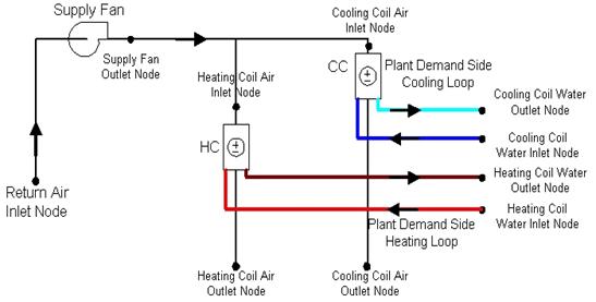
Figure 119. Example Air Loop Heating & Cooling Coil
The water cooling coil (Coil:Cooling:Water) has the ability to give detailed output with simplified inputs, inputting complicated coil geometry is not required by the user for this model instead the coil is sized in terms of auto-sizeable thermodynamic inputs. The coil requires thermodynamic inputs such as temperatures, mass flow rates and humidity ratios.
The coil is sized using auto-sized/user design input conditions and the UA values are calculated from the design conditions. A rough estimate of the coil area is provided along with percentage of surface wet and/or dry. This model uses the NTU-effectiveness approach to model heat transfer and has two types of flow arrangements cross-flow or counter-flow.
The basic underlying idea is - use auto sizable thermodynamic design inputs, calculate the coil UA’s, use these UA values and operating conditions from the nodes connections, calculate the outlet stream conditions, and calculate the heat transfer rates.
See section “Cooling Coil Model” in the EnergyPlus Engineering Document for further details regarding this model.
A unique user-assigned name for an instance of a cooling coil. Any reference to this cooling coil by another object will use this name.
Schedule that defines when the coil is available. The name of the schedule (ref: Schedule) that denotes whether the cooling coil can run during a given time period. A schedule value greater than 0 (usually 1 is used) indicates that the unit can be on during a given time period. A value less than or equal to 0 (usually 0 is used) denotes that the unit is off.
The maximum possible water volume flow rate (m3/sec) through the coil. This is an auto sizable design input.
The maximum possible air volume flow rate (m3/sec) through the coil. This is an auto sizable design input.
The inlet water temperature for the design flow (deg C). This is an auto sizable design input.
The inlet air temperature for the design flow (deg C). This is an auto sizable design input.
The outlet air condition desired for design flow ( deg C). This is an auto sizable design input.
The highest value of humidity ratio possible for the Design inlet air stream. This is an auto sizable input.
The value of humidity ratio for the Design outlet air stream, it is an auto sizable input.
The name of the water coil inlet from the chilled water loop, i.e. Cooling Coil Water Inlet Node. It is from this node the operating inputs for water are transferred to the coil.
The name of the water coil outlet from the chilled water loop, i.e. Cooling Coil Water Outlet Node. It is from this node the operating output for water are reported to the coil.
The name of the air inlet to the water coil, i.e. Cooling Coil Air Inlet Node. It is from this node the operating inputs for air are transferred to the coil.
The name of the air outlet from the water coil, i.e. Cooling Coil Air Outlet Node. It is from this node the operating output for airside is reported to the coil.
The coil has two modes of operation, termed as SimpleAnalysis and DetailedAnalysis. The difference between the two modes being, the simple mode reports the value of surface area fraction wet of the coil as dry or wet. The detailed mode give the exact value, however the execution time in detailed mode is noticeably higher.
The coil is operable in two modes, Cross Flow for general A/C applications and Counter flow mode. Air-conditioning systems generally use cross flow heat exchangers, hence the default is set to cross flow.
This field is optional. It is used to describe where condensate from the coil is collected. If blank or omitted, then any coil condensate is discarded. Enter the name of Water Storage Tank object defined elsewhere and the condensate will then be collected in that tank.
Examples when auto sized in an IDF are as below:
Coil:Cooling:Water,
Main Cooling Coil 1, !- Coil Name
CoolingCoilAvailSched, !- Available Schedule
autosize, !- Design Water Volume Flow Rate of Coil {m3/s}
autosize, !- Design Air Flow Rate of Coil {m3/s}
autosize, !- Design Inlet Water Temperature {C}
autosize, !- Design Inlet Air Temperature {C}
autosize, !- Design Outlet Air Temperature {C}
autosize, !- Design Inlet Air Humidity Ratio
autosize, !- Design Outlet Air Humidity Ratio
Main Cooling Coil 1 Water Inlet Node, !- Coil_Water_Inlet_Node
Main Cooling Coil 1 Water Outlet Node, !- Coil_Water_Outlet_Node
Mixed Air Node 1, !- Coil_Air_Inlet_Node
Main Cooling Coil 1 Outlet Node; !- Coil_Air_Outlet_Node
Examples when values (hard-sized) are input in an IDF are as below:
Coil:Cooling:Water,
Main Cooling Coil 1, !- Coil Name
CoolingCoilAvailSched, !- Available Schedule
0.0022, !- Design Water Volume Flow Rate of Coil {m3/s}
1.45, !- Design Air Flow Rate of Coil {m3/s}
6.1, !- Design Inlet Water Temperature {C}
25, !- Design Inlet Air Temperature {C}
10, !- Design Outlet Air Temperature {C}
0.012, !- Design Inlet Air Humidity Ratio
0.008, !- Design Outlet Air Humidity Ratio
Main Cooling Coil 1 Water Inlet Node, !- Coil_Water_Inlet_Node
Main Cooling Coil 1 Water Outlet Node, !- Coil_Water_Outlet_Node
Mixed Air Node 1, !- Coil_Air_Inlet_Node
Main Cooling Coil 1 Outlet Node; !- Coil_Air_Outlet_Node
Following are the list of possible output report variables from this coil model:
HVAC,Sum,Total Water Cooling Coil Energy[J]
HVAC,Sum,Sensible Water Cooling Coil Energy[J]
HVAC,Average,Total Water Cooling Coil Rate[W]
HVAC,Average,Sensible Water Cooling Coil Rate[W]
HVAC,Average,Cooling Coil Area Wet Fraction
HVAC,Average,Cooling Coil Condensate Volumetric Flow Rate [m3/s]
Zone,Meter,OnSiteWater:Facility [m3]
Zone,Meter,OnSiteWater:HVAC [m3]
Zone,Meter,Condensate:OnSiteWater [m3]
HVAC,Sum,Cooling Coil Condensate Volume [m3]
Total Water Cooling Coil Energy is the total amount of heat transfer taking place in the coil at the operating conditions.
Sensible Water Cooling Coil Energy is the total amount of Sensible heat transfer taking place in the coil at the operating conditions. It only takes into account temperature difference in the inlet and outlet air streams at operating conditions.
Total Water Cooling Coil Rate is the Rate of heat transfer taking place in the coil at the operating conditions. The units are (J/sec) or Watts.
Sensible Water Cooling Coil Rate is the Rate of Sensible heat transfer taking place in the coil at the operating conditions.
It defines the fraction of total surface area of coil which is wet due to moisture condensation on the surface of the coil. Value varies between 0.0 and 1.0.
In addition, if a Water Storage Tank is used to collect coil condensate, then the following outputs will be available.
These reports provide the rate and amount of condensate from the coil. Condensate is water condensed out of the air as a result of cooling. The condensate volume is also reported on the meter for “OnSiteWater.”
This simple heating coil model only does sensible heating of the air. The simple heating coil uses the Effectiveness-NTU algorithm and assumes a cross-flow heat exchanger.
A unique identifying name for each coil.
Schedule that defines when the coil is available.
The UA value for the coil needed for the Effectiveness-NTU heat exchanger model. An estimate of the UA can be obtained from:
![]()
where q is the heat transferred from water to the air in watts; Twater, avg is the average water temperature in degrees C; and Tair, avg is the average air temperature in degrees C. Or the LMTD temperature difference can be used. This field is used when Performance Input Method = UFactorTimesAreaAndDesignWaterFlowRate.This field is autosizable.
The maximum possible water flow rate (m3/sec) through the coil. This field is used when Coil Performance Input Method = UFactorTimesAreaAndDesignWaterFlowRate. This field is autosizable.
The name of the coil’s water inlet node from the hot water loop.
The name of the coil’s water outlet node from the hot water loop.
The name of the air inlet node to the water coil.
The name of the air outlet node from the water coil.
The user can choose either UFactorTimesAreaAndDesignWaterFlowRate or NominalCapacity. If UFactorTimesAreaAndDesignWaterFlowRate is selected, the user must input values for UA of the Coil and Max Water FlowRate of the Coil (and Rated Capacity is ignored). If NominalCapacity is chosen, the user must input a Rated Capacity for the coil; UA of the Coil and Max Water FlowRate of the Coil will be ignored. Rated capacity is defined as the heating capacity in watts of the coil at the rating points (i.e., the rated inlet and outlet water/air temperatures defined in the input fields below). The rated capacity is used to calculate a water mass flow rate and a UA for the coil. The default is NominalCapacity.
To autosize the capacity, choose UfactorTimesAreaAndDesignWaterFlowRate and put autosize as the inputs for U-Factor Times Area Value, Maximum Water Flow Rate, and Rated Capacity. The program will use the Sizing inputs to size the coil. The rated temperatures (see below) are ignored in autosizing. These are used only when the user is specifying coil performance using the NominalCapacity input method.
The heating capacity of the coil in watts at the rated inlet and outlet air and water temperatures. This field is used when the Performance Input Method = Nominal Capacity. This field is autosizable. The rating points are given in the four subsequent input fields.
The inlet water temperature (degrees C) corresponding to the rated heating capacity. The default is 82.2 degrees C (180 degrees F).
The inlet air temperature (degrees C) corresponding to the rated heating capacity. The default is 16.6 degrees C (60 degrees F).
The outlet water temperature (degrees C) corresponding to the rated heating capacity. The default is 71.1 degrees C (160 degrees F).
The outlet air temperature (degrees C) corresponding to the nominal heating capacity. The default is 32.2 degrees C (90 degrees F).
This is the ratio of convective heat transfers between air side and water side of the heating coil at the rated operating conditions. The default is 1.0. This ratio describes the geometry and the design of the coil and is defined by:

where,
![]() is the fin efficiency, (dimensionless)
is the fin efficiency, (dimensionless)
h is the surface convection heat transfer coefficient
A is the surface area
An example input of the object is:
Coil:Heating:Water,
SPACE3-1 Zone Coil, !- Coil Name
ReheatCoilAvailSched, !- Available Schedule
, !- UA of the Coil {W/K}
, !- Max Water Flow Rate of Coil {m3/s}
SPACE3-1 Zone Coil Water In Node, !- Coil_Water_Inlet_Node
SPACE3-1 Zone Coil Water Out Node, !- Coil_Water_Outlet_Node
SPACE3-1 Zone Coil Air In Node, !- Coil_Air_Inlet_Node
SPACE3-1 In Node, !- Coil_Air_Outlet_Node
NominalCapacity, !- Coil Performance Input Method
10000., !- Rated Capacity
0.55; !- Rated Ratio for Air and Water Convection
HVAC,Sum, Total Water Heating Coil Energy[J]
HVAC,Average,Total Water Heating Coil Rate[W]
HVAC,Average,Water Heating Coil U-factor Times Area [W]
Total Water Heating Coil Energy is the total amount of heat transfer taking place in the coil at the operating conditions.
Total Water Heating Coil Rate is the Rate of heat transfer taking place in the coil at the operating conditions. The units are (J/sec) or Watts.
This characterizes the overall heat transfer “UA” value, or U-factor times Area. The simple heating coil model adjusts UA value based on inlet temperatures and flow rates and this output contains the results from that adjustment.
The simple steam to air heating coil model only does sensible heating of the air. The steam to air coils condenses the steam and sub cools steam at loop pressure and discharges the condensate through steam traps at low pressure condensate line.
A unique identifying name for each steam coil.
Schedule that defines when the coil is available.
The maximum possible steam flow rate (m3/sec) through the coil. This field is autosizable.
Ideally the steam trap located at the outlet of steam coil should remove all the condensate immediately, however there is a delay in this process in actual systems which causes the condensate to SubCool by certain degree in the coil before leaving the coil, this SubCool occurs in the steam coil and this SubCool-heat is added to the zone. The minimum value is 2B Celsius and default is 5B Celsius.
This essentially represents the heat loss to the atmosphere due to uninsulated condensate return piping to the boiler. Condensate return piping operates at atmospheric pressure and is not insulated. The condensate sub cools to certain degree before it is pumped back to the boiler. The minimum value is 10B Celsius and default is 20B Celsius.
The name of the steam coil inlet from the steam loop, i.e. Steam Coil steam inlet node.
The name of the steam coil outlet to the condensate loop, i.e. Steam Coil condensate outlet node.
The name of the air inlet to the steam coil, i.e. Steam Coil Air Inlet Node.
The name of the air outlet from the steam coil, i.e. Steam Coil Air Outlet Node.
Choice of either ZoneLoadControl steam coil or TemperatureSetpointControl steam coil. A zone coil is load controlled and an air loop steam coil is temperature controlled.
If the coil is used in the air loop simulation and is temperature controlled using a Set Point Manager (i.e., the previous file is TemperatureSetpointConrtol), then the node that is the control node needs to be specified here. If the coil is used in an air terminal unit, the coil is load controlled and a control node set point is not required (i.e., the previous field is ZoneLoadControl).
An example of a Steam Coil input statement (one each for Temperature Controlled and Load Controlled) from an IDF is given below:
Coil:Heating:Steam,
VAV SYS 1 Heating Coil, !- Coil Name
ReheatCoilAvailSched, !- Available Schedule
0.06, !- Max Steam volume Flow rate
5.0, !- Deg of Subcooling Desired
15.0, !- Loop Subcooling Desired
VAV SYS 1 Heating Coil Steam Inlet, !- Coil Steam Inlet Node
VAV SYS 1 Heating Coil Steam Outlet, !- Coil Water Outlet Node
VAV SYS 1 Cooling Coil Outlet, !- Coil Air Inlet Node
VAV SYS 1 Heating Coil Outlet, !- Coil Air Outlet Node
TemperatureSetPointControl, !- field Coil Control Type
VAV SYS 1 Heating Coil Outlet; !- field Coil Temp Setpoint Node
Coil:Heating:Steam,
SPACE1-1 Reheat Coil, !- Coil Name
ReheatCoilAvailSched, !- Available Schedule
autosize, !- Max Steam volume Flow rate
5.0, !- Deg of Subcooling Desired
15.0, !- Loop Subcooling Desired
SPACE1-1 Reheat Coil Steam Inlet, !- Coil Steam Inlet Node
SPACE1-1 Reheat Coil Steam Outlet, !- Coil Water Outlet Node
SPACE1-1 Damper Outlet, !- Coil Air Inlet Node
SPACE1-1 Supply Inlet, !- Coil Air Outlet Node
ZoneLoadControl; !- field Coil Control Type
HVAC,Sum, Total Steam Coil Heating Energy[J]
HVAC,Average,Total Steam Coil Heating Rate[W]
HVAC,Average,Loop Losses[W]
HVAC, Average, Steam Coil Inlet Temp[C]
HVAC, Average, Steam Coil Outlet Temp [C]
HVAC, Average, Steam Coil Mass Flow Rate [kg/s]
Total Steam Heating Coil Energy is the total amount of heat transfer taking place in the coil at the operating conditions.
Total Steam Heating Coil Rate is the Rate of heat transfer taking place in the coil at the operating conditions. The units are (J/sec) or Watts.
Loop losses represent the unavoidable loss due to degree of sub cooling in the condensate return piping back to the boiler and the loss occurring due to flashing of steam across the steam trap due to pressure differential between the steam and the condensate side.
These outputs are the Steam inlet and condensate outlet temperatures and steam flow rate for the boiler.
The electric heating coil is a simple capacity model with a user-inputted efficiency. In many cases, this efficiency for the electric coil will be 100%. This coil will be simpler than shown in Figure 119 since it will only have air nodes to connect it in the system. The coil can be used in the air loop simulation or in the zone equipment as a reheat coil. Depending on where it is used determines if this coil is temperature or capacity controlled. If used in the air loop simulation it will be controlled to a specified temperature scheduled from the SetPoint Manager. If it is used in zone equipment, it will be controlled from the zone thermostat by meeting the zone demand.
A unique identifying name for each coil.
Schedule that defines when the coil is available.
This is user-inputted efficiency (decimal units, not percent) and can account for any loss. In most cases for the electric coil, this will be 100%.
This is the maximum capacity of the coil (W). This controlled coil will only provide the needed capacity to meet the control criteria whether it is temperature or capacity controlled. This field is autosizable.
The name of the air inlet to the electric coil, i.e. Heating Coil Air Inlet Node.
The name of the air outlet from the electric coil, i.e. Heating Coil Air Outlet Node.
If the coil is used in the air loop simulation and is temperature controlled using a Set Point Manager, then the node that is the control node needs to be specified here. If the coil is used in an air terminal unit, the coil is load controlled and a control node set point is not required.
An example in IDF form:
An example of IDF usage:
Coil:Heating:Electric,
AHU Reheater, !- Name
2, !- Availability Schedule Name
0.99, !- Efficiency
600000, !- Nominal Capacity {W}
DOAS Supply Fan Outlet, !- Air Inlet Node Name
AHU Reheater Outlet, !- Air Outlet Node Name
AHU Reheater Outlet; !- Temperature Setpoint Node Name
HVAC,Sum,Heating Coil Energy[J]
HVAC,Average,Heating Coil Rate[W]
HVAC,Sum,Heating Coil Electric Consumption [J]
HVAC,Average,Heating Coil Electric Power [W]
Heating Coil Energy is the total amount of heat transfer taking place in the coil at the operating conditions.
Heating Coil Rate is the Rate of heat transfer taking place in the coil at the operating conditions. The units are (J/sec) or Watts.
Heating Coil electric consumption after the efficiency of the coil has been taken into account in Joules for the timestep reported.
This field is the average Heating Coil electric power after the efficiency of the coil has been taken into account in Watts for the timestep reported.
A simplified approach is used to determine the performance of this air heating coil. The model assumes that the heating energy provided by this coil is reclaimed from the superheated refrigerant gas leaving a compressor (i.e., a desuperheating refrigerant-to-air heating coil) and does not impact the performance of the compressor. This coil can be used in air loop simulations but can’t be used by certain compound objects (e.g., UnitarySystem: AirToAir:HeatPump, UnitarySystem:WaterToAir:HeatPump, or Desiccant Dehumidifier:Solid) or any air distribution equipment (e.g., Single Duct:Const Volume:Reheat, Single Duct:VAV:Reheat, or Single Duct:Series PIU:Reheat).
The desuperheater heating coil input requires a coil name, an availability schedule, and a heat reclaim recovery efficiency. The reclaim recovery efficiency determines the amount of heat available for use by this heating coil. Approximately 25-30% of the energy rejected by typical refrigeration system condensers is to reduce the superheated refrigerant vapor temperature to the condensing temperature. Recovery efficiencies higher than 30% may cause the refrigerant gas to condense which in turn impacts the performance of the refrigeration system. For this reason, the maximum heat reclaim recovery efficiency for this coil is 30% for most sources of waste heat, including refrigeration compressor racks. The one exception to this 30% limit is a condenser that is part of a detailed refrigeration system. In a detailed refrigeration system, the portion of the rejected heat that lies within the superheated region is explicitly calculated. Therefore, the desuperheater coils supplied by a condenser attached to a detailed refrigeration system are subject to a maximum reclaim recovery efficiency of 90% of the heat within the superheated region.
The next two input items for the desuperheater heating coil are the node names for the inlet and outlet air streams. The following two input fields define the source of heating energy for the coil. This desuperheater heating coil may only be used with direct expansion (DX) cooling or refrigeration equipment. The first of these two inputs is the heating source object type while the second defines the name of the heating source. For proper modeling, the desuperheater heating coil must be placed downstream of a DX cooling coil when reclaiming heat from that cooling coil. Desuperheating heating coil placement is unrestricted when reclaiming heat from a Refrigeration:CompressorRack or Refrigeration:Condenser.
The next input field is optional and defines the set point node name if the desuperheater heating coil is to be controlled based on temperature. When a load-based control scheme is used, this field is left blank. A final optional input is used to model parasitic electric energy use of auxiliary equipment associated with the desuperheater heating coil (e.g., solenoid valve).
This alpha field defines a unique user-assigned name for an instance of a desuperheater heating coil. Any reference to this desuperheater heating coil by another object will use this name.
This alpha field defines the name of the schedule (ref: Schedule) that denotes whether the desuperheater heating coil can run during a given time period. Schedule values must range from 0 to 1. A schedule value greater than 0 indicates that the coil can operate during the time period. A value equal to 0 denotes that the coil must be off for that time period.
This numeric field defines the ratio of recovered waste heat from the superheated refrigerant gas to the total rejected waste heat from the heating source (as if no heat reclaim occurred). Values can range from 0.0 up to a maximum of 0.9 if the source is a refrigeration condenser and 0.3 for all other waste heat sources. If this input field is left blank, the default value is 0.8 for a refrigeration condenser source type and 0.25 for all other sources.
This alpha field defines the name of the HVAC system node from which the desuperheater heating coil draws its inlet air.
This alpha field defines the name of the HVAC system node to which the desuperheater heating coil sends its outlet air.
This alpha field defines the source of superheated refrigerant gas from which the desuperheater heating coil recovers energy. Valid choices are:
Coil:Cooling:DX:SingleSpeed
Coil:Cooling:DX:TwoSpeed
Coil:Cooling:DX:TwoStageWithHumidityControlMode
Refrigeration:CompressorRack
Refrigeration:Condenser:AirCooled
Refrigeration:Condenser:EvaporativeCooled
Refrigeration:Condenser:WaterCooled
When the heating coil source is a DX Coil, the air loop’s supply air fan control mode may be auto fan (cycling fan cycling coil), constant fan, or variable volume. When the heating source is a compressor rack for refrigerated cases or a refrigeration condenser, the supply air fan control mode should be either variable volume or constant fan.
NOTE: Use of the desuperheater heating coil in variable air volume systems should be done with caution since the model assumption of a fixed heat reclaim recovery efficiency may not be valid if the air flow rate over the coil varies significantly.
This alpha field defines the name of the desuperheater heating coil source (e.g., the name of a specific valid coil (as mentioned in the previous field) which provides waste heat to this desuperheater heating coil).
NOTE: When the heating source is a Refrigeration Compressor rack, the heat rejection location in the Refrigeration:CompressorRack object must be “Outdoors”. If the compressor rack heat rejection location is “Zone”, the total amount of heat rejection available for reclaim (e.g., by this desuperheater heating coil) is set to zero by the compressor rack object and the simulation proceeds.
This optional alpha field defines the name of the HVAC system node used for temperature-based control (e.g., controlling the heating coil’s outlet air dry-bulb temperature to a setpoint). If the desuperheater heating coil is temperature controlled through the use of a Set Point Manager, then the control node specified in the Set Point Manager will be entered here. If the desuperheater heating coil is controlled based on a certain heating load to be met (e.g., using this heating coil as part of UnitarySystem:BlowThru:HeatCool for high humidity control), this field should be left blank.
This optional numeric field defines the parasitic electric load (in Watts) due to control valves or other devices specific to the desuperheater heating coil. The load is applied whenever the coil is heating the air. The model assumes that this electric load is small and does not contribute to heating the air.
Following is an example input for a desuperheater heating coil.
Coil:Heating:Desuperheater,
DesuperheaterCoil, !- Coil Name
FanAndCoilAvailSched, !- Availability Schedule
0.3, !- Heat Reclaim Recovery Efficiency
Cooling Coil Air Outlet Node, !- Coil Air Inlet Node Name
Air Loop Outlet Node, !- Coil Air Outlet Node Name
Coil:Cooling:DX:SingleSpeed, !- Heating Source Type
Furnace ACDXCoil 1, !- Heating Source Name
, !- Coil Temperature Setpoint Node Name
0.1; !- Parasitic Electric Load {W}
HVAC,Average,Heating Coil Rate [W]
HVAC,Sum,Heating Coil Energy [J]
HVAC,Average,Heating Coil Electric Power [W]
HVAC,Sum,Heating Coil Electric Consumption [J]
HVAC,Average,Heating Coil Runtime Fraction
This output is the average heating rate of the desuperheater heating coil in Watts over the timestep being reported. This is determined by the coil inlet and outlet air conditions and the air mass flow rate through the coil.
This output is the total heating output of the desuperheater heating coil in Joules over the timestep being reported. This is determined by the coil inlet and outlet air conditions and the air mass flow rate through the coil. This output is also added to a report meter with Resource Type = EnergyTransfer, End Use Key = HeatingCoils, Group Key = System (ref. Report Meter).
This output is the average electric consumption rate for the parasitic load associated with the desuperheater heating coil in Watts.
This output is the electric consumption of the desuperheater heating coil parasitic load in Joules for the timestep being reported. This output is also added to a report meter with Resource Type = Electricity, End Use Key = Heating, Group Key = System (ref. Report Meter).
This is the runtime fraction of the desuperheater heating coil for the timestep being reported. Since the desuperheater heating coil can only provide heat when the heat source object is active, the runtime fraction of the desuperheater heating coil will always be less than or equal to the runtime fraction of the heat source object.
The variable refrigerant flow (VRF) DX cooling coil model is nearly identical to the single-speed DX cooling coil model (Ref. Coil:DX:CoolingBypassFactorEmpirical). For this reason, an adaptation of the single-speed DX cooling coil model is used to model the variable-speed compression system used in VRF AC systems. The model inputs are quite similar to the input requirements for the single-speed DX cooling coil model, however, the location of a majority of the inputs have been moved to the variable refrigerant flow air conditioner object since multiple DX cooling coils will use the same DX compression system (Ref. AirConditioner:VariableRefrigerantFlow).
This alpha field defines a unique user-assigned name for an instance of a VRF DX cooling coil. Any reference to this DX cooling coil by another object will use this name. This cooling coil name must be entered in the AirConditioner:VariableRefrigerantFlow object. No other sytem type uses this specific coil.
This alpha field defines the name of the DX cooling coil availabiltiy schedule. Schedule values of 0 denote the DX cooling coil is off.
This numeric field defines the rated total cooling capacity of the DX cooling coil. The total cooling capacity should be a “gross” value and not include thermal affects due to the supply air fan.
This numeric field defines the sensible heat ratio (sensible capacity divided by total cooling capacity) of the DX cooling coil at rated conditions. Both the sensible and total cooling capacities used to define the Rated SHR should be “gross” (i.e., supply air fan heat is NOT included)
The air volume flow rate, in m3 per second, across the DX cooling coil at rated conditions. The rated air volume flow rate should be between 0.00004027 m3/s and 0.00006041 m3/s per watt of rated total cooling capacity (300 to 450 cfm/ton). The rated total cooling capacity and rated SHR should be performance information for the unit with at this rated air volume flow rate.
This alpha field defines the cooling capacity ratio modifier as a function of indoor wet-bulb temperature or indoor wet-bulb and outdoor dry-bulb temperatures. This curve is a linear, quadratic, or cubic curve if the cooling capacity is soley a function of indoor wet-bulb temperature (i.e., the indoor terminal units weighted average inlet air wet-bulb temperatures). Without specific manufacturers data indicating otherwise, the use of a single independent variable is recommended for this coil type. If, however, the user has reason to believe the cooling capacity is both a function of indoor wet-bulb temperature and outdoor dry-bulb temperature (and has manufacturers data to create the performance curve), a bi-quadratic equation using weighted average indoor wet-bulb temperature and condenser entering air dry-bulb temperature as the independent variables may be used. See the Engineering Reference for more discussion on using this input field.
This alpha field defines the name of a linear, quadratic or cubic performance curve (ref: Performance Curves) that parameterizes the variation of total cooling capacity as a function of the ratio of actual air flow rate across the cooling coil to the rated air flow rate (i.e., fraction of full load flow). The output of this curve is multiplied by the rated total cooling capacity and the total cooling capacity modifier curve (function of temperature) to give the total cooling capacity at the specific temperature and air flow conditions at which the coil is operating. The curve is normalized to have the value of 1.0 when the actual air flow rate equals the rated air flow rate.
This alpha field defines the name of the air inlet node entering the DX cooling coil.
This alpha field defines the name of the air outlet node exiting the DX cooling coil.
This field is optional. It is used to describe where condensate from the coil is collected. If blank or omitted, then any coil condensate is discarded. Enter the name of Water Storage Tank object defined elsewhere and the condensate will then be collected in that tank.
Following is an example input for a Coil:Cooling:DX:VariableRefrigerantFlow object.
COIL:Cooling:DX:VariableRefrigerantFlow,
TU1 VRF DX Cooling Coil, !- Coil Name
VRFAvailSched, !- Availability Schedule Name
autosize, !- Rated Total Cooling Capacity {W}
autosize, !- Rated Sensible Heat Ratio
autosize, !- Rated Air Flow Rate {m3/s}
VRFTUCoolCapFT, !- Cooling Capacity Ratio Modifier Function of Temperature Curve Name
VRFACCoolCapFFF, !- Cooling Capacity Modifier Curve Function of Flow Fraction Name
TU1 VRF DX CCoil Inlet Node, !- Coil Air Inlet Node
TU1 VRF DX CCoil Outlet Node; !- Coil Air Outlet Node
HVAC,Average, DX Coil Total Cooling Rate[W]
HVAC,Sum, DX Coil Total Cooling Energy[J]
HVAC,Average, DX Coil Sensible Cooling Rate[W]
HVAC,Sum, DX Coil Sensible Cooling Energy[J]
HVAC,Average, DX Coil Latent Cooling Rate[W]
HVAC,Sum, DX Coil Latent Cooling Energy[J]
HVAC,Average, DX Cooling Coil Runtime Fraction
Evaporative-cooled condenser:
HVAC,Average,DX Cooling Coil Condensate Volumetric Flow Rate [m3/s]
Zone,Meter,Condensate:OnSiteWater [m3]
HVAC,Sum,DX Cooling Coil Condensate Volume [m3]
This field is the total (sensible and latent) cooling rate output of the DX coil in Watts. This is determined by the coil inlet and outlet air conditions and the air mass flow rate through the coil.
This is the total (sensible plus latent) cooling output of the DX coil in Joules over the time step being reported. This is determined by the coil inlet and outlet air conditions and the air mass flow rate through the coil. This output is also added to a report meter with Resource Type = EnergyTransfer, End Use Key = CoolingCoils, Group Key = System (Ref. Report Meter).
This output is the moist air sensible cooling rate output of the DX coil in Watts. This is determined by the inlet and outlet air conditions and the air mass flow rate through the coil.
This is the moist air sensible cooling output of the DX coil in Joules for the time step being reported. This is determined by the inlet and outlet air conditions and the air mass flow rate through the coil.
This is the latent cooling rate output of the DX coil in Watts. This is determined by the inlet and outlet air conditions and the air mass flow rate through the coil.
This is the latent cooling output of the DX coil in Joules for the time step being reported. This is determined by the inlet and outlet air conditions and the air mass flow rate through the coil.
This is the runtime fraction of the DX coil compressor and condenser fan(s) for the time step being reported.
These outputs are the rate and volume of water collected as condensate from the coil. These reports only appear if a water storage tank is named in the input object.
The variable refrigerant flow (VRF) DX heating coil model uses performance information at rated conditions along with performance curves for variations in total capacity, energy input ratio and part load fraction to determine performance at part-load conditions. The impacts of defrost operation is modeled based a combination of user inputs and empirical models taken from the air-to-air heat pump algorithms in DOE-2.1E.
The VRF DX heating coil input requires an availability schedule, the rated total heating capacity and the rated air volume flow rate. The rated air volume flow rate should be between 0.00008056 m3/s and 0.00002684 m3/s per watt of rated total heating capacity.
Two performance curves are required. The first performance curve defines the total heating capacity as a function of indoor air dry-bulb and outdoor condenser entering air wet-bulb temperature. This curve object is specified in the variable refrigerant flow air-to-air heat pump object. The second performance curve is specific the each VRF DX heating coil and defines the change in total heating capacity as a function of air flow fraction. Each of these performance curves are further discussed here.
1) Total heating capacity modifier curve (function of temperature, specified in Heat Pump)
The total heating capacity modifier curve (function of temperature) can be a function of both the outdoor wet-bulb temperature and indoor air dry-bulb temperature. Users have the choice of a bi-quadratic curve with two independent variables or a tri-quadratic curve with three independent variable. The tri-quadratic curve is recommended if sufficient manufacturer data is available as it provides sensitivity to the combined total capacity of all indoor units connected to the heat pump condenser and a more realistic output. The output of this curve is multiplied by the rated total heating capacity to give the total heating capacity at specific temperature operating conditions (i.e., at an outdoor or indoor air temperature different from the rating point temperature) and the combination ratio of the installed system.
2) Total heating capacity modifier curve (function of flow fraction, specified in DX coil)
The total heating capacity modifier curve (function of flow fraction) is a quadratic or cubic curve with the independent variable being the ratio of the actual air flow rate across the heating coil to the rated air flow rate (i.e., fraction of full load flow). The output of this curve is multiplied by the rated total heating capacity and the total heating capacity modifier curve (function of temperature) to give the total heating capacity at the specific temperature and air flow conditions at which the coil is operating.
This alpha field defines a unique user-assigned name for an instance of a VRF DX heating coil. Any reference to this DX heating coil by another object will use this name.
This alpha field defines the name of the schedule (ref: Schedule) that denotes whether the DX heating coil can run during a given hour. A schedule value greater than 0 (usually 1 is used) indicates that the unit can be on during the hour. A value less than or equal to 0 (usually 0 is used) denotes that the unit must be off for the hour.
This numeric field defines the total, full load heating capacity in watts of the DX coil unit at rated conditions (outside air dry-bulb temperature of 8.33 C, outside air wet-bulb temperature of 6.11 C, heating coil entering air dry-bulb temperature of 21.11 C, heating coil entering air wet-bulb temperature of 15.55 C, and a heating coil air flow rate defined by field “rated air flow volume” below). The value entered here must be greater than 0. Capacity should not include supply air fan heat.
This numeric field defines the volume air flow rate, in m3 per second, across the DX heating coil at rated conditions. The value entered here must be greater than 0. The rated air volume flow rate should be between 0.00004027 m3/s and 0.00006041 m3/s per watt of rated total heating capacity. The rated total heating capacity and rated COP should be performance information for the unit with outside air dry-bulb temperature of 8.33 C, outside air wet-bulb temperature of 6.11 C, heating coil entering air dry-bulb temperature of 21.11 C, heating coil entering air wet-bulb temperature of 15.55 C, and the rated air volume flow rate defined here.
This alpha field defines the name of the HVAC system node from which the DX heating coil draws its inlet air.
This alpha field defines the name of the HVAC system node to which the DX heating coil sends its outlet air.
This alpha field defines the heating capacity ratio modifier as a function of indoor dry-bulb temperature or indoor dry-bulb and outdoor wet-bulb temperatures. This curve is a linear, quadratic, or cubic curve if the heating capacity is soley a function of indoor dry-bulb temperature (i.e., the indoor terminal units weighted average inlet air dry-bulb temperatures). Without specific manufacturers data indicating otherwise, the use of a single independent variable is recommended for this coil type. If, however, the user has reason to believe the heating capacity is both a function of indoor dry-bulb temperature and outdoor wet-bulb temperature (and has manufacturers data to create the performance curve), a bi-quadratic equation using weighted average indoor dry-bulb temperature and condenser entering air wet-bulb temperature as the independent variables may be used. See the Engineering Reference for more discussion on using this input field.
Note: The choice of using either outdoor dry-bulb temperature or outdoor wet-bulb temperature as the independent variable in this performance curve is set in the parent object AirConditioner: VariableRefrigerantFlow.
This alpha field defines the name of a linear, quadratic or cubic performance curve (ref: Performance Curves) that parameterizes the variation of total heating capacity as a function of the ratio of actual air flow rate across the heating coil to the rated air flow rate (i.e., fraction of full load flow). The output of this curve is multiplied by the rated total heating capacity and the total heating capacity modifier curve (function of temperature) to give the total heating capacity at the specific temperature and air flow conditions at which the coil is operating. The curve is normalized to have the value of 1.0 when the actual air flow rate equals the rated air flow rate.
Following is an example input for the object.
COIL:Heating:DX:VariableRefrigerantFlow,
TU1 VRF DX Heating Coil, !- Coil Name
VRFAvailSched, !- Availability Schedule
autosize, !- Rated Total Heating Capacity {W}
autosize, !- Rated Air Flow Rate {m3/s}
TU1 VRF DX CCoil Outlet Node, !- Coil Air Inlet Node
TU1 VRF DX HCoil Outlet Node, !- Coil Air Outlet Node
VRFTUHeatCapFT, !- Heating Capacity Ratio Modifier Function of Temperature Curve Name
VRFACCoolCapFFF; !- Total heating capacity modifier curve Function of Flow Fraction
HVAC,Average, DX Coil Total Heating Rate[W]
HVAC,Sum, DX Coil Total Heating Energy[J]
HVAC,Average, DX Cooling Coil Runtime Fraction
This field is the total heating rate output of the DX coil in Watts. This is determined by the coil inlet and outlet air conditions and the air mass flow rate through the coil.
This is the total heating output of the DX coil in Joules over the time step being reported. This is determined by the coil inlet and outlet air conditions and the air mass flow rate through the coil. This output is also added to a report meter with Resource Type = EnergyTransfer, End Use Key = HeatingCoils, Group Key = System (ref. Report Meter).
This is the runtime fraction of the DX coil compressor and condenser fan(s) for the time step being reported.
The gas heating coil is a simple capacity model with a user inputted gas burner efficiency. The default for the gas burner efficiency is 80%. This coil will be simpler than shown in Figure 119 since it will only have air nodes to connect it in the system. The coil can be used in the air loop simulation or in the zone equipment as a reheat coil. Depending on where it is used determines if this coil is temperature or capacity controlled. If used in the air loop simulation it will be controlled to a specified temperature scheduled from the Setpoint Manager. If it is used in zone equipment, it will be controlled from the zone thermostat by meeting the zone demand.
A unique identifying name for each coil.
Schedule that defines when the coil is available.
This is user inputted gas burner efficiency (decimal, not percent) and is defaulted to 80%.
This is the maximum capacity of the coil (W). This controlled coil will only provide the needed capacity to meet the control criteria whether it is temperature or capacity controlled. This field is autosizable.
The name of the air inlet to the gas coil, i.e. Heating Coil Air Inlet Node.
The name of the air outlet from the gas coil, i.e. Heating Coil Air Outlet Node.
If the coil is used in the air loop simulation and is temperature controlled using a Set Point Manager, then the node that is the control node needs to be specified here. If the coil is used in an air terminal unit, the coil is load controlled and a control node set point is not required.
This is the parasitic electric load associated with the gas coil operation, such as an inducer fan, etc.. This will be modified by the PLR (or coil runtime fraction if a part-load fraction correlation is provided in the next input field) to reflect the time of operation in a simulation timestep.
This alpha field defines the name of a quadratic or cubic performance curve (Ref: Performance Curves) that parameterizes the variation of gas consumption rate by the heating coil as a function of the part load ratio (PLR, sensible heating load/nominal capacity of the heating coil). For any simulation timestep, the nominal gas consumption rate (heating load/burner efficiency) is divided by the part-load fraction (PLF) if a part-load curve has been defined. The part-load curve accounts for efficiency losses due to transient coil operation.
The part-load fraction correlation should be normalized to a value of 1.0 when the part load ratio equals 1.0 (i.e., no efficiency losses when the heating coil runs continuously for the simulation timestep). For PLR values between 0 and 1 ( 0 <= PLR < 1), the following rules apply:
PLF >= 0.7 and PLF >= PLR
If PLF < 0.7 a warning message is issued, the program resets the PLF value to 0.7, and the simulation proceeds. The runtime fraction of the heating coil is defined a PLR/PLF. If PLF < PLR, then a warning message is issues and the runtime fraction of the coil is limited to 1.0.
A typical part load fraction correlation for a conventional gas heating coil (e.g., residential furnace) would be:
PLF = 0.8 + 0.2(PLR)
This numeric field is the parasitic gas load associated with the gas coil’s operation (Watts), such as a standing pilot light. The model assumes that this parasitic load is consumed only for the portion of the simulation timestep where the gas heating coil is not operating.
HVAC,Sum,Heating Coil Energy[J]
HVAC,Average,Heating Coil Rate[W]
HVAC,Sum,Heating Coil Gas Consumption [J]
HVAC,Average,Heating Coil Gas Consumption Rate [W]
HVAC,Sum,Heating Coil Electric Consumption [J]
HVAC,Average,Heating Coil Electric Power [W]
HVAC,Average,Heating Coil Runtime Fraction
HVAC,Sum,Heating Coil Parasitic Gas Consumption [J]
HVAC,Average,Heating Coil Parasitic Gas Consumption Rate [W]
This field is the total heating output of the coil in Joules over the timestep being reported. This output is also added to a report meter with Resource Type = EnergyTransfer, End Use Key = HeatingCoils, Group Key = System (ref. Report Meter).
This field is the average heating rate output of the coil in Watts over the timestep being reported.
This field is the gas consumption of the heating coil in Joules over the timestep being reported, including the impacts of part-load performance if a part load fraction correlation is specified. This output is also added to a report meter with Resource Type = Gas, End Use Key = Heating, Group Key = System (ref. Report Meter).
This field is the average gas consumption rate of the coil in Watts over the timestep being reported, including the impacts of part-load performance if a part load fraction correlation is specified.
This field is the electric consumption of the heating coil auxiliaries in Joules over the timestep being reported (e.g., inducer fan). This output is also added to a report meter with Resource Type = Electricity, End Use Key = Heating, Group Key = System (ref. Report Meter).
This field is the average electric consumption rate of the heating coil auxiliaries (e.g., inducer fan) in Watts over the timestep being reported.
This field is the parasitic gas consumption of the heating coil in Joules over the timestep being reported (e.g., standing pilot light). The model assumes that the parasitic load is accumulated only for the portion of the simulation timestep where the gas heating coil is not operating. This output is also added to a report meter with Resource Type = Gas, End Use Key = Heating, Group Key = System (ref. Report Meter).
This field is the average parasitic gas consumption rate of the heating coil (e.g., standing pilot light) in Watts over the timestep being reported. The model assumes that the parasitic load is present only for the portion of the simulation timestep where the gas heating coil is not operating.
This detailed flat fin coil model is for continuous plate fins. First, found in Type 12 from MODSIM, but now programmed directly from Elmahdy, A.H. and Mitalas, G.P. Then there was a discontinuity in their original model that was fixed in the EnergyPlus implementation. Now this model can be used in an interval halving solution technique for controlling this coil without the problems of non-convergence.
"A Model for Cooling and Dehumidifying Coils for Use in Energy Requirements for Buildings" ASHRAE Transactions, Vol. 83, Part 2, pp. 103-117 (1977). For fin efficiency see K.A. Gardner, "Efficiency of Extended ," Transactions ASME, Vol. 67, pp. 621-631, 1945.
The following figures illustrate the geometry and circuits in a cooling coil.
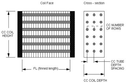
Figure 120. Geometry of a Cooling Coil (CC)
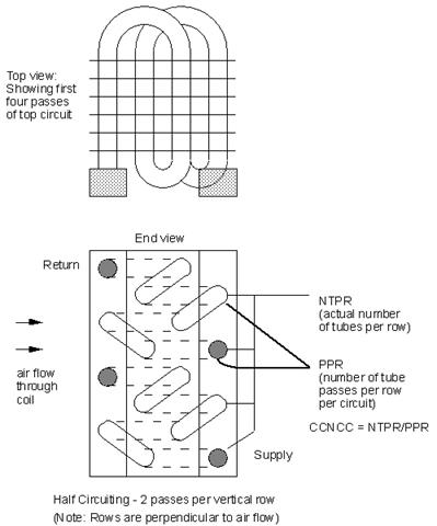
Figure 121. Number of Coolant Circuits (CCNCC)
A unique identifying name for each coil.
Schedule that defines when the coil is available.
The maximum possible water flow rate (m3/sec) through the coil.
The outside surface area (m2) of the tubes that is exposed to air (i.e. the outside area of the unfinned tubes minus the area of tubes covered by the fins).
The total surface area (m2) inside the tubes (water side).
The total surface area (m2) of the fins attached to the coil.
The minimum cross sectional area (m2) available for air passage. Frequently calculated as
Amin = (Amin/Afr)*Afr
where Afr is the frontal area of the heat exchanger, and (Amin/Afr) is the ratio of the minimum airflow area to frontal area.
The distance (m) from the front of the coil to the back of the coil in the airflow direction. Also called the fin depth. Illustrated in the figure (Figure 120. Geometry of a Cooling Coil (CC)).
The outside diameter (m) of the fins. Used instead of COIL HEIGHT
Thickness (m) of the air side fins.
The inside diameter (m) of the tubes.
The outside diameter (m) of the tubes.
The thermal conductivity (W/m-K) of the tube material.
The thermal conductivity (W/m-K) of the fin material.
The spacing (m) of the fins, centerline to centerline.
The spacing (m) of the tube rows, centerline to centerline. Also called tube longitudinal spacing.
The number of tube rows in the direction of the airflow.
The number of tubes per row. (NTPR in the above diagram)
The name of the water coil inlet from the chilled water loop, i.e. Cooling Coil Water Inlet Node.
The name of the water coil outlet from the chilled water loop, i.e. Cooling Coil Water Outlet Node.
The name of the air inlet to the water coil, i.e. Cooling Coil Air Inlet Node.
The name of the air outlet from the water coil, i.e. Cooling Coil Air Outlet Node.
This field is optional. It is used to describe where condensate from the coil is collected. If blank or omitted, then any coil condensate is discarded. Enter the name of Water Storage Tank object defined elsewhere and the condensate will then be collected in that tank.
Examples of these statements in an IDF are:
Coil:Cooling:Water:DetailedGeometry,
Detailed Cooling Coil, !Name of cooling coil
CoolingCoilAvailSched, !Cooling Coil Schedule
0.0011, !Max Water Flow Rate of Coil m3/sec
6.23816, !Tube Outside Surf Area
6.20007018, !Tube Inside Surf Area
101.7158224, !Fin Surf Area
0.300606367, !Min Air Flow Area
0.165097968, !Coil Depth
0.43507152, !Coil Height
0.001499982, !Fin Thickness
0.014449958, !Tube Inside Diameter
0.015879775, !Tube Outside Diameter
386.0, !Tube Thermal Conductivity
204.0, !Fin Thermal Conductivity
0.001814292, !Fin Spacing
0.02589977, !Tube Depth
6, !Number of Tube Rows
16, !Number of Tubes per Row
NODE_32,NODE_33, !Coil Water Side Inlet & Outlet Node
NODE_5, NODE_6; !Coil Air Side Inlet & Outlet Node
HVAC,Sum,Total Water Cooling Coil Energy[J]
HVAC,Sum,Sensible Water Cooling Coil Energy[J]
HVAC,Average,Total Water Cooling Coil Rate[W]
HVAC,Average,Sensible Water Cooling Coil Rate[W]
HVAC,Average,Cooling Coil Condensate Volumetric Flow Rate [m3/s]
Zone,Meter,OnSiteWater:Facility [m3]
Zone,Meter,OnSiteWater:HVAC [m3]
Zone,Meter,Condensate:OnSiteWater [m3]
HVAC,Sum,Cooling Coil Condensate Volume [m3]
Total Water Cooling Coil Energy is the total amount of heat transfer taking place in the coil at the operating conditions.
Sensible Water Cooling Coil Energy is the total amount of Sensible heat transfer taking place in the coil at the operating conditions. It only takes into account temperature difference in the inlet and outlet air streams at operating conditions.
Total Water Cooling Coil Rate is the Rate of heat transfer taking place in the coil at the operating conditions. The units are (J/sec) or Watts.
Sensible Water Cooling Coil Rate is the Rate of Sensible heat transfer taking place in the coil at the operating conditions.
In addition, if a Water Storage Tank is used to collect coil condensate, then the following outputs will be available.
These reports provide the rate and amount of condensate from the coil. Condensate is water condensed out of the air as a result of cooling. The condensate volume is also reported on the meter for “OnSiteWater.”
This DX cooling coil model and input are quite different from that for the heating and cooling water coils. The simple water coils use an NTU-effectiveness heat exchanger model. The single speed DX coil model uses performance information at rated conditions along with curve fits for variations in total capacity, energy input ratio and part-load fraction to determine performance at part-load conditions. Sensible/latent capacity splits are determined by the rated sensible heat ratio (SHR) and the apparatus dewpoint/bypass factor (ADP/BF) approach. This approach is analogous to the NTU-effectiveness calculations used for sensible-only heat exchanger calculations, extended to a cooling and dehumidifying coil.
This DX cooling coil input requires an availability schedule, the rated total cooling capacity, the rated SHR, the rated COP, and the rated air volume flow rate. The latter 4 inputs determine the coil performance at the rating point (air entering the cooling coil at 26.7°C drybulb/19.4°C wetbulb and air entering the outdoor condenser coil at 35°C drybulb/23.9°C wetbulb). The rated air volume flow rate should be between .00004027 m3/s and .00006041 m3/s per watt of rated total cooling capacity (300 to 450 cfm/ton).
This model requires 5 curves as follows:
1. The total cooling capacity modifier curve (function of temperature) is a biquadratic curve with two independent variables: wet-bulb temperature of the air entering the cooling coil, and dry-bulb temperature of the air entering the air-cooled condenser coil (wet-bulb temperature if modeling an evaporative-cooled condenser). The output of this curve is multiplied by the rated total cooling capacity to give the total cooling capacity at specific temperature operating conditions (i.e., at temperatures different from the rating point temperatures).
2. The total cooling capacity modifier curve (function of flow fraction) is a quadratic or cubic curve with the independent variable being the ratio of the actual air flow rate across the cooling coil to the rated air flow rate (i.e., fraction of full load flow). The output of this curve is multiplied by the rated total cooling capacity and the total cooling capacity modifier curve (function of temperature) to give the total cooling capacity at the specific temperature and air flow conditions at which the coil is operating.
3. The energy input ratio (EIR) modifier curve (function of temperature) is a biquadratic curve with two independent variables: wet-bulb temperature of the air entering the cooling coil, and dry-bulb temperature of the air entering the air-cooled condenser coil (wet-bulb temperature if modeling an evaporative-cooled condenser). The output of this curve is multiplied by the rated EIR (inverse of the rated COP) to give the EIR at specific temperature operating conditions (i.e., at temperatures different from the rating point temperatures).
4. The energy input ratio (EIR) modifier curve (function of flow fraction) is a quadratic or cubic curve with the independent variable being the ratio of the actual air flow rate across the cooling coil to the rated air flow rate (i.e., fraction of full load flow). The output of this curve is multiplied by the rated EIR (inverse of the rated COP) and the EIR modifier curve (function of temperature) to give the EIR at the specific temperature and air flow conditions at which the coil is operating.
5. The part load fraction correlation (function of part load ratio) is a quadratic or cubic curve with the independent variable being part load ratio (sensible cooling load / steady-state sensible cooling capacity). The output of this curve is used in combination with the rated EIR and EIR modifier curves to give the “effective” EIR for a given simulation timestep. The part load fraction (PLF) correlation accounts for efficiency losses due to compressor cycling. The curve should be normalized to a value of 1.0 when the part-load ratio equals 1.0 (i.e., the compressor(s) run continuously for the simulation timestep).
The curves are simply specified by name. Curve inputs are described in the curve manager section of this document (see Performance Curves in this document).
The next four input fields are optional and relate to the degradation of latent cooling capacity when the supply air fan operates continuously while the cooling coil/compressor cycle on and off to meet the cooling load. The fan operating mode is determined in the partent object and is considered to either be constant (e.g. AirLoopHVAC:UnitaryCoolOnly) or can be scheduled (e.g. AirLoopHVAC:UnitaryHeatCool). When scheduled, the schedule value must be greater than 0 to calculate degradation of latent cooling capacity. At times when the parent object’s supply air fan operating mode schedule is 0, latent degradation will be ignored. When modeling latent capacity degradation, these next four input fields must all have positive values.
The next input specifies the outdoor air node used to define the conditions of the air entering the outdoor condenser. If this field is left blank, the outdoor temperature entering the condenser is taken directly from the weather data. If this field is not blank, the node name specified must be listed in an OutdoorAir:Node object where the height of the node is taken into consideration when calculating outdoor temperature from the weather data. Alternately, the node name must be specified in an OutdoorAir:NodeList object where the outdoor temperature entering the condenser is taken directly from the weather data.
The next input describes the type of outdoor condenser coil used with the DX cooling coil (Air Cooled or Evap Cooled). The following three inputs are required when modeling an evaporative-cooled condenser: evaporative condenser effectiveness, evaporative condenser air volume flow rate, and the power consumed by the evaporative condenser pump. Crankcase heater capacity and cutout temperature are entered in the next two input fields. The final two fields for this object define the name of the water storage tank for supply and condensate collection. See section “DX Cooling Coil Model” in the EnergyPlus Engineering Document for further details regarding this model.
A unique user-assigned name for an instance of a DX cooling coil. Any reference to this DX coil by another object will use this name.
The name of the schedule (ref: Schedule) that denotes whether the DX cooling coil can run during a given time period. A schedule value greater than 0 (usually 1 is used) indicates that the unit can be on during a given time period. A value less than or equal to 0 (usually 0 is used) denotes that the unit must be off.
The total, full load cooling capacity (sensible plus latent) in watts of the DX coil unit at rated conditions (air entering the cooling coil at 26.7°C drybulb/19.4°C wetbulb, air entering the outdoor condenser coil at 35°C drybulb/23.9°C wetbulb[9], and a cooling coil air flow rate defined by field “rated air volume flow rate” below). Capacity should be “gross” (i.e., supply air fan heat is NOT included). When used in a heat pump, the rated total cooling capacity should be within 20% of the rated total heating capacity, otherwise a warning message is issued.
The sensible heat ratio (SHR=sensible capacity divided by total cooling capacity) of the DX cooling coil at rated conditions (air entering the cooling coil at 26.7°C drybulb/19.4°C wetbulb, air entering the outdoor condenser coil at 35°C drybulb/23.9°C wetbulb, and a cooling coil air flow rate defined by field “rated air volume flow rate” below). Both the sensible and total cooling capacities used to define the Rated SHR should be “gross” (i.e., supply air fan heat is NOT included).
The coefficient of performance (cooling power output in watts divided by electrical power input in watts) of the DX cooling coil unit at rated conditions (air entering the cooling coil at 26.7°C drybulb/19.4°C wetbulb, air entering the outdoor condenser coil at 35°C drybulb/ 23.9°C wetbulb, and a cooling coil air flow rate defined by field “rated air volume flow rate” below). The input power includes electric power for the compressor(s) and condenser fan(s) but does not include the power consumption of the supply air fan. The cooling power output is the value entered above in the field “Rated Total Cooling Capacity (gross)”. If this input field is left blank, the default value is 3.0.
The air volume flow rate, in m3 per second, across the DX cooling coil at rated conditions. The rated air volume flow rate should be between 0.00004027 m3/s and 0.00006041 m3/s per watt of rated total cooling capacity (300 to 450 cfm/ton). The rated total cooling capacity, rated SHR and rated COP should be performance information for the unit with air entering the cooling coil at 26.7°C drybulb/19.4°C wetbulb, air entering the outdoor condenser coil at 35°C drybulb/23.9°C wetbulb, and the rated air volume flow rate defined here.
This field is the electric power for the evaporator (cooling coil) fan per air volume flow rate through the coil at the rated conditions in W/(m3/s). The default value is 773.3 W/(m3/s) (365 W/1000 cfm) if this field is left blank. If a value is entered, it must be >= 0.0 and <= 1250 W/(m3/s). This value is only used to calculate Seasonal Energy Efficiency Ratio (SEER), Energy Efficiency Ratio (EER), Integrated Energy Efficiency Ratio (IEER) and the Standard Rating (Net) Cooling Capacity which will be outputs in the EnergyPlus eio file (ref. EnergyPlus Engineering Reference, Single Speed DX Cooling Coil, Standard Ratings). This value is not used for modeling the evaporator (cooling coil) fan during simulations; instead, it is used for calculating SEER, EER, IEER and Standard Rating Cooling Capacity to assist the user in verifying their inputs for modeling this type of equipment.
The name of the HVAC system node from which the DX cooling coil draws its inlet air.
The name of the HVAC system node to which the DX cooling coil sends its outlet air.
The name of a biquadratic performance curve (ref: Performance Curves) that parameterizes the variation of the total cooling capacity as a function of the wet-bulb temperature of the air entering the cooling coil, and the dry-bulb temperature of the air entering the air-cooled condenser coil (wet-bulb temperature if modeling an evaporative-cooled condenser). The output of this curve is multiplied by the rated total cooling capacity to give the total cooling capacity at specific temperature operating conditions (i.e., at temperatures different from the rating point temperatures). The curve is normalized to have the value of 1.0 at the rating point.
The name of a quadratic or cubic performance curve (ref: Performance Curves) that parameterizes the variation of total cooling capacity as a function of the ratio of actual air flow rate across the cooling coil to the rated air flow rate (i.e., fraction of full load flow). The output of this curve is multiplied by the rated total cooling capacity and the total cooling capacity modifier curve (function of temperature) to give the total cooling capacity at the specific temperature and air flow conditions at which the coil is operating. The curve is normalized to have the value of 1.0 when the actual air flow rate equals the rated air flow rate.
The name of a biquadratic performance curve (ref: Performance Curves) that parameterizes the variation of the energy input ratio (EIR) as a function of the wet-bulb temperature of the air entering the cooling coil, and the dry-bulb temperature of the air entering the air-cooled condenser coil (wet-bulb temperature if modeling an evaporative-cooled condenser). The EIR is the inverse of the COP. The output of this curve is multiplied by the rated EIR (inverse of rated COP) to give the EIR at specific temperature operating conditions (i.e., at temperatures different from the rating point temperatures). The curve is normalized to a value of 1.0 at the rating point.
The name of a quadratic or cubic performance curve (Ref: Performance Curves) that parameterizes the variation of the energy input ratio (EIR) as a function of the ratio of actual air flow rate across the cooling coil to the rated air flow rate (i.e., fraction of full load flow). The EIR is the inverse of the COP. The output of this curve is multiplied by the rated EIR and the EIR modifier curve (function of temperature) to give the EIR at the specific temperature and air flow conditions at which the cooling coil is operating. This curve is normalized to a value of 1.0 when the actual air flow rate equals the rated air flow rate.
This alpha field defines the name of a quadratic or cubic performance curve (Ref: Performance Curves) that parameterizes the variation of electrical power input to the DX unit as a function of the part load ratio (PLR, sensible cooling load/steady-state sensible cooling capacity). The product of the rated EIR and EIR modifier curves is divided by the output of this curve to give the “effective” EIR for a given simulation timestep. The part load fraction (PLF) correlation accounts for efficiency losses due to compressor cycling.
The part load fraction correlation should be normalized to a value of 1.0 when the part load ratio equals 1.0 (i.e., no efficiency losses when the compressor(s) run continuously for the simulation timestep). For PLR values between 0 and 1 (0 <= PLR < 1), the following rules apply:
PLF >= 0.7 and PLF >= PLR
If PLF < 0.7 a warning message is issued, the program resets the PLF value to 0.7, and the simulation proceeds. The runtime fraction of the coil is defined as PLR/PLF. If PLF < PLR, then a warning message is issued and the runtime fraction of the coil is limited to 1.0.
A typical part load fraction correlation for a conventional, single-speed DX cooling coil (e.g., residential unit) would be:
PLF = 0.85 + 0.15(PLR)
If the user wishes to model no efficiency degradation due to compressor cycling, the part load fraction correlation should be defined as follows:
PLF = 1.0 + 0.0(PLR)
The nominal time (in seconds) after startup for condensate to begin leaving the coil's condensate drain line at the coil's rated airflow and temperature conditions, starting with a dry coil. Nominal time is equal to the ratio of the energy of the coil's maximum condensate holding capacity (J) to the coil's steady-state latent capacity (W). Suggested value is 1000; zero value means the latent degradation model is disabled. The default value for this field is zero. The supply air fan operating mode must be continuous (i.e., the supply air fan operating mode may be specified in other ”parent” objects and is assumed continuous in some objects (e.g., AirloopHVAC:UnitaryCoolOnly) or can be scheduled in other objects [e.g., AirloopHVAC:UnitaryHeatCool]), and this field as well as the next three input fields for this object must have positive values in order to model latent capacity degradation.
Ratio of the initial moisture evaporation rate from the cooling coil (when the compressor first turns off, in Watts) and the coil's steady-state latent capacity (Watts) at rated airflow and temperature conditions. Suggested value is 1.5; zero value means the latent degradation model is disabled. The default value for this field is zero. The supply air fan operating mode must be continuous (i.e., the supply air fan operating mode may be specified in other ”parent” objects and is assumed continuous in some objects (e.g., AirloopHVAC:UnitaryCoolOnly) or can be scheduled in other objects [e.g., AirloopHVAC:UnitaryHeatCool]); and this field, the previous field and the next two fields must have positive values in order to model latent capacity degradation.
The maximum on-off cycling rate for the compressor (cycles per hour), which occurs at 50% run time fraction. Suggested value is 3; zero value means latent degradation model is disabled. The default value for this field is zero. The supply air fan operating mode must be continuous (i.e., the supply air fan operating mode may be specified in other ”parent” objects and is assumed continuous in some objects (e.g., AirloopHVAC:UnitaryCoolOnly) or can be scheduled in other objects [e.g., AirloopHVAC:UnitaryHeatCool]); and this field, the previous two fields and the next field must have positive values in order to model latent capacity degradation.
Time constant (in seconds) for the cooling coil's latent capacity to reach steady state after startup. Suggested value is 45; zero v The supply air fan operating mode must be continuous (i.e., the supply air fan operating mode may be specified in other ”parent” objects and is assumed continuous in some objects (e.g., AirloopHVAC:UnitaryCoolOnly) or can be scheduled in other objects [e.g., AirloopHVAC:UnitaryHeatCool]), and this field as well as the previous three input fields for this object must have positive values in order to model latent capacity degradation.
This optional alpha field specifies the outdoor air node name used to define the conditions of the air entering the outdoor condenser. If this field is left blank, the outdoor air temperature entering the condenser (dry-bulb or wet-bulb) is taken directly from the weather data. If this field is not blank, the node name specified must also be specified in an OutdoorAir:Node object where the height of the node is taken into consideration when calculating outdoor air temperature from the weather data. Alternately, the node name may be specified in an OutdoorAir:NodeList object where the outdoor air temperature is taken directly from the weather data.
The effectiveness of the evaporative condenser, which is used to determine the temperature of the air entering the outdoor condenser coil as follows:
![]()
where
Tcond inlet = the temperature of the air entering the condenser coil (C)
Twb,o= the wet-bulb temperature of the outdoor air (C)
Tdb,o= the dry-bulb temperature of the outdoor air (C)
The resulting condenser inlet air temperature is used by the Total Cooling Capacity Modifier Curve (function of temperature) and the Energy Input Ratio Modifier Curve (function of temperature). The default value for this field is 0.9, although valid entries can range from 0.0 to 1.0. This field is not used when Condenser Type = Air Cooled.
If the user wants to model an air-cooled condenser, they should simply specify AirCooled in the field Condenser Type. In this case, the Total Cooling Capacity Modifier Curve (function of temperature) and the Energy Input Ratio Modifier Curve (function of temperature) input fields for this object should reference performance curves that are a function of outdoor dry-bulb temperature.
If the user wishes to model an evaporative-cooled condenser AND they have performance curves that are a function of the wet-bulb temperature of air entering the condenser coil, then the user should specify Condenser Type = Evap Cooled and the evaporative condenser effectiveness value should be entered as 1.0. In this case, the Total Cooling Capacity Modifier Curve (function of temperature) and the Energy Input Ratio Modifier Curve (function of temperature) input fields for this object should reference performance curves that are a function of the wet-bulb temperature of air entering the condenser coil.
If the user wishes to model an air-cooled condenser that has evaporative media placed in front of it to cool the air entering the condenser coil, then the user should specify Condenser Type = Evap Cooled. The user must also enter the appropriate evaporative effectiveness for the media. In this case, the Total Cooling Capacity Modifier Curve (function of temperature) and the Energy Input Ratio Modifier Curve (function of temperature) input fields for this object should reference performance curves that are a function of outdoor dry-bulb temperature. Be aware that the evaporative media will significantly reduce the dry-bulb temperature of the air entering the condenser coil, so the Total Cooling Capacity and EIR Modifier Curves must be valid for the expected range of dry-bulb temperatures that will be entering the condenser coil.
The air volume flow rate, in m3 per second, entering the evaporative condenser. This value is used to calculate the amount of water used to evaporatively cool the condenser inlet air. The minimum value for this field must be greater than zero, and this input field is autosizable (equivalent to 0.000144 m3/s per watt of rated total cooling capacity [850 cfm/ton]). This field is not used when Condenser Type = Air Cooled.
The rated power of the evaporative condenser water pump in Watts. This value is used to calculate the power required to pump the water used to evaporatively cool the condenser inlet air. The default value for this input field is zero, but it is autosizable (equivalent to 0.004266 W per watt [15 W/ton] of rated total cooling capacity). This field is not used when Condenser Type = Air Cooled.
This numeric field defines the crankcase heater capacity in Watts. When the outdoor air dry-bulb temperature is below the value specified in the input field “Maximum Outdoor Dry-bulb Temperature for Crankcase Heater Operation” (described below), the crankcase heater is enabled during the time that the compressor is not running. If this cooling coil is used as part of an air-to-air heat pump (Ref. UnitarySystem:HeatPump:AirToAir or PackageTerminal: HeatPump:AirToAir), the crankcase heater defined for this DX cooling coil is ignored and the crankcase heater power defined for the DX heating coil (Ref. Coil:Heating:DX:SingleSpeed) is enabled during the time that the compressor is not running for either heating or cooling. The value for this input field must be greater than or equal to 0, and the default value is 0. To simulate a DX cooling coil without a crankcase heater, enter a value of 0.
This numeric field defines the outdoor air dry-bulb temperature above which the compressor’s crankcase heater is disabled. The value for this input field must be greater than or equal to 0.0°C, and the default value is 10°C.
This field is optional. It is used to describe where the coil obtains water used for evaporative cooling of its condenser. If blank or omitted, then the unit will obtain water directly from the mains. If the name of a Water Storage Tank object is used here, then the unit will obtain its water from that tank. If a tank is specified, the unit will attempt to obtain all the water it uses from the tank. However if the tank cannot provide all the water the condenser needs, then the unit will still operate and obtain the rest of the water it needs from the mains (referred to as StarvedWater).
This field is optional. It is used to describe where condensate from the coil is collected. If blank or omitted, then any coil condensate is discarded. Enter the name of Water Storage Tank object defined elsewhere and the condensate will then be collected in that tank.
This numeric field contains the capacity of the DX coil’s electric evaporative cooler basin heater in watts per degree Kelvin. This field only applies for Condenser Type = EvaporativelyCooled. This field is used in conjunction with the Basin Heater Setpoint Temperature described in the following field. The basin heater electric power is equal to this field multiplied by the difference between the basin heater set point temperature and the outdoor dry-bulb temperature. The basin heater only operates when the DX coil is off, regardless of the basin heater schedule described below. The basin heater capacity must be greater than or equal to zero, with a default value of zero if this field is left blank.
This numeric field contains the set point temperature (˚C) for the basin heater described in the previous field. This field only applies for Condenser Type = EvaporativelyCooled. The basin heater is active when the outdoor air dry-bulb temperature falls below this setpoint temperature, as long as the DX coil is off. This set point temperature must be greater than or equal to 2˚C, and the default value is 2˚C if this field is left blank.
This alpha field contains the name of the basin heater operating schedule. This field only applies for Condenser Type = EvaporativelyCooled. The basin heater operating schedule is assumed to be an on/off schedule and the heater is available to operate any time the schedule value is greater than 0. The basin heater operates when scheduled on and the outdoor air dry-bulb temperature is below the set point temperature described in the previous field. If this field is left blank, the basin heater is available to operate throughout the simulation. Regardless of this schedule, the basin heater may only operate when the DX coil is off.
Following is an example input for a Coil:Cooling:DX:SingleSpeed coil.
Coil:Cooling:DX:SingleSpeed,
Zone1WindACDXCoil, ! Coil Name
FanAndCoilAvailSched, ! Availability Schedule
10548, ! Rated Total Cooling Capacity (gross)
0.75, ! Rated SHR
3.0, ! Rated COP
0.637, ! Rated Air Volume Flow Rate (m3/s)
773.3, ! Rated Evaporator Fan Power Per Volume Flow Rate {W/(m3/s)}
Zone1WindACFanOutletNode, ! Coil Air Inlet Node
Zone1WindACAirOutletNode, ! Coil Air Outlet Node
WindACCoolCapFT, ! Total Cooling Capacity Modifier Curve (function of temperature)
WindACCoolCapFFF, ! Total Cooling Capacity Modifier Curve (function of flow fraction)
WindACEIRFT, ! Energy Input Ratio Modifier Curve (function of temperature)
WindACEIRFFF, ! Energy Input Ratio Modifier Curve (function of flow fraction)
WindACPLFFPLR, ! Part Load Fraction Correlation (function of part load ratio)
1000., ! Nominal Time for Condensate Removal to Begin {s}
1.5, ! Ratio of Initial Moisture Evaporation Rate and Steady-state Latent Capacity
3.0, ! Maximum ON/OFF Cycling Rate {cycles/hr}
45.0, ! Latent Capacity Time Constant {s}
, ! Condenser Air Inlet Node Name
AirCooled, ! Condenser Type
, ! Evaporative Condenser Effectiveness
, ! Evaporative Condenser Air Volume Flow Rate {m3/s}
, ! Evaporative Condenser Pump Rated Power Consumption {W}
30., ! Crankcase Heater Capacity {W}
10.; ! Maximum Outdoor Dry-bulb Temperature for Crankcase Heater Operation {C}
This component models a two-speed (or variable speed) DX compressor and fan. The method is based on the model used for the cycling, single speed DX unit. The single speed unit is described by single full load capacity, SHR, COP, and air flow rate at rated conditions. Off rated full load performance is obtained by the use of 4 modifier curves. At partial load the unit cycles on/off and the cycling losses are described by a part load fraction curve.
The multispeed unit is described by specifying the performance at two states: high speed compressor, high speed fan; and low speed compressor, low speed fan. When the unit load is above the high speed capacity, the unit runs with high speed compressor and fan. When the load on the unit is below the high speed capacity but above the low speed capacity, the unit will run with performance intermediate between high speed and low speed. When the load is less than the low speed capacity, the unit will cycle on/off just like the single speed unit.
The multispeed unit model requires 2 full sets of performance data. There must be a high and low speed capacity, SHR, COP, and evaporator air flow rate; as well as high and low speed performance curves – total cooling capacity modifier curve (function of temperature) and energy input ratio modifier curve (function of temperature).
The multispeed DX component should be used for all cases in which a DX VAV system is being simulated. Obviously this model – in which performance is obtained by interpolating between 2 specified states - is an oversimplification of how real multi-speed and variable speed DX cooling units are controlled. But detailed descriptions of how actual units perform and are controlled are not available. This model should give a good average prediction of multispeed and variable speed DX cooling unit performance.
A unique user-assigned name for an instance of a multispeed DX cooling coil. Any reference to this DX coil by another object will use this name.
The name of the schedule (ref: Schedule) that denotes whether the DX cooling coil can run during a given hour. A schedule value greater than 0 (usually 1 is used) indicates that the unit can be on during the hour. A value less than or equal to 0 (usually 0 is used) denotes that the unit must be off for the hour.
The total, full load cooling capacity (sensible plus latent) in watts of the DX coil unit for high speed compressor and high speed fan at rated conditions (air entering the cooling coil at 26.7°C drybulb/19.4°C wetbulb, air entering the outdoor condenser coil at 35°C drybulb/23.9°C wetbulb, and a cooling coil air flow rate defined by field “rated air volume flow rate” below). Capacity should be “gross” (i.e., supply air fan heat is NOT included).
The sensible heat ratio (sensible capacity divided by total cooling capacity) of the DX cooling coil for high speed compressor and high speed fan at rated conditions (air entering the cooling coil at 26.7°C drybulb/19.4°C wetbulb, air entering the outdoor condenser coil at 35°C drybulb/23.9°C wetbulb[10], and a cooling coil air flow rate defined by field “rated air volume flow rate” below). Both the sensible and total cooling capacities used to define the Rated SHR should be “gross” (i.e., supply air fan heat is NOT included).
The coefficient of performance (cooling power output in watts divided by electrical power input in watts) of the DX cooling coil unit for high speed compressor and high speed fan at rated conditions (air entering the cooling coil at 26.7°C drybulb/19.4°C wetbulb, air entering the outdoor condenser coil at 35°C drybulb/23.9°C wetbulb, and a cooling coil air flow rate defined by field “rated air volume flow rate” below)The input power includes electric power for the compressor(s) and condenser fan(s) but does not include the power consumption of the supply air fan. The cooling power output is the value entered above in the field “Rated Total Cooling Capacity (gross)”. If this input field is left blank, the default value is 3.0.
The high speed air volume flow rate, in m3 per second, across the DX cooling coil at rated conditions. The rated air volume flow rate should be between 0.00004027 m3/s and 0.00006041 m3/s per watt of rated total cooling capacity. The rated total cooling capacity, rated SHR and rated COP should be performance information for the unit with air entering the cooling coil at 26.7°C drybulb/19.4°C wetbulb, air entering the outdoor condenser coil at 35°C drybulb/23.9°C wetbulb, and the rated air volume flow rate defined here.
The name of the HVAC system node from which the DX cooling coil draws its inlet air.
The name of the HVAC system node to which the DX cooling coil sends its outlet air.
The name of a biquadratic performance curve (ref: Performance Curves) that parameterizes the variation of the total cooling capacity as a function of the wet-bulb temperature of the air entering the cooling coil, and the dry-bulb temperature of the air entering the air-cooled condenser (wet-bulb temperature if modeling an evaporative-cooled condenser). The output of this curve is multiplied by the rated total cooling capacity to give the total cooling capacity at specific temperature operating conditions (i.e., at temperatures different from the rating point temperatures). The curve is normalized to have the value of 1.0 at the rating point. This curve is used for performance at the high speed compressor, high speed fan operating point.
The name of a quadratic performance curve (ref: Performance Curves) that parameterizes the variation of total cooling capacity as a function of the ratio of actual air flow rate across the cooling coil to the rated air flow rate (i.e., fraction of full load flow). The output of this curve is multiplied by the rated total cooling capacity and the total cooling capacity modifier curve (function of temperature) to give the total cooling capacity at the specific temperature and air flow conditions at which the coil is operating. The curve is normalized to have the value of 1.0 when the actual air flow rate equals the rated air flow rate. This curve is applied only at the high speed compressor, high speed fan operating point. There is no corresponding curve for the low speed operating point.
The name of a biquadratic performance curve (ref: Performance Curves) that parameterizes the variation of the energy input ratio (EIR) as a function of the wet-bulb temperature of the air entering the cooling coil and the dry-bulb temperature of the air entering the air-cooled condenser (wet-bulb temperature if modeling an evaporative-cooled condenser). The EIR is the inverse of the COP. The output of this curve is multiplied by the rated EIR (inverse of rated COP) to give the EIR at specific temperature operating conditions (i.e., at temperatures different from the rating point temperatures). The curve is normalized to a value of 1.0 at the rating point. This curve is used for performance at the high speed compressor, high speed fan operating point.
The name of a quadratic performance curve (Ref: Performance Curves) that parameterizes the variation of the energy input ratio (EIR) as a function of the ratio of actual air flow rate across the cooling coil to the rated air flow rate (i.e., fraction of full load flow). The EIR is the inverse of the COP. The output of this curve is multiplied by the rated EIR and the EIR modifier curve (function of temperature) to give the EIR at the specific temperature and air flow conditions at which the cooling coil is operating. This curve is normalized to a value of 1.0 when the actual air flow rate equals the rated air flow rate. This curve is applied only at the high speed compressor, high speed fan operating point. There is no corresponding curve for the low speed operating point.
This alpha field defines the name of a quadratic or cubic performance curve (Ref: Performance Curves) that parameterizes the variation of electrical power input to the DX unit as a function of the part load ratio (PLR, sensible cooling load/steady-state sensible cooling capacity). The product of the rated EIR and EIR modifier curves is divided by the output of this curve to give the “effective” EIR for a given simulation timestep. The part load fraction (PLF) correlation accounts for efficiency losses due to compressor cycling.
The part load fraction correlation should be normalized to a value of 1.0 when the part load ratio equals 1.0 (i.e., no efficiency losses when the compressor(s) run continuously for the simulation timestep). For PLR values between 0 and 1 (0 <= PLR < 1), the following rules apply:
PLF >= 0.7 and PLF >= PLR
If PLF < 0.7 a warning message is issued, the program resets the PLF value to 0.7, and the simulation proceeds. The runtime fraction of the coil is defined as PLR/PLF. If PLF < PLR, then a warning message is issued and the runtime fraction of the coil is limited to 1.0.
A typical part load fraction correlation for a conventional, single-speed DX cooling coil (e.g., residential unit) would be:
PLF = 0.85 + 0.15(PLR)
If the user wishes to model no efficiency degradation due to compressor cycling, the part load fraction correlation should be defined as follows:
PLF = 1.0 + 0.0(PLR)
The total, full load cooling capacity (sensible plus latent) in watts of the DX coil unit for low speed compressor and low speed fan at rated conditions (air entering the cooling coil at 26.7°C drybulb/19.4°C wetbulb, air entering the outdoor condenser coil at 35°C drybulb/23.9°C wetbulb, and a cooling coil air flow rate defined by field “rated air volume flow rate, low speed” below). Capacity should be “gross” (i.e., supply air fan heat is NOT included).
The sensible heat ratio (SHR=sensible capacity divided by total cooling capacity) of the DX cooling coil for low speed compressor and low speed fan at rated conditions (air entering the cooling coil at 26.7°C drybulb/19.4°C wetbulb, air entering the outdoor condenser coil at 35°C drybulb/23.9°C wetbulb, and a cooling coil air flow rate defined by field “rated air volume flow rate, low speed” below). Both the sensible and total cooling capacities used to define the Rated SHR should be “gross” (i.e., supply air fan heat is NOT included).
The coefficient of performance (COP=cooling power output in watts divided by electrical power input in watts) of the DX cooling coil unit for low speed compressor and low speed fan at rated conditions (air entering the cooling coil at 26.7°C drybulb/19.4°C wetbulb, air entering the outdoor condenser coil at 35°C drybulb/23.9°C wetbulb, and a cooling coil air flow rate defined by field “rated air volume flow rate, low speed” below). The input power includes power for the compressor(s) and condenser fan(s) but does not include the power consumption of the supply air fan. The cooling power output is the value entered above in the field “Rated Total Cooling Capacity (gross)”. If this input field is left blank, the default value is 3.0.
The low speed volume air flow rate, in m3 per second, across the DX cooling coil at rated conditions. The rated air volume flow rate should be between 0.00004027 m3/s and 0.00006041 m3/s per watt of rated total cooling capacity. The rated total cooling capacity, rated SHR and rated COP should be performance information for the unit with air entering the cooling coil at 26.7°C drybulb/19.4°C wetbulb, air entering the outdoor condenser coil at 35°C drybulb/23.9°C wetbulb, and the rated air volume flow rate defined here.
The name of a biquadratic performance curve (ref: Performance Curves) that parameterizes the variation of the total cooling capacity as a function of the wet-bulb temperature of the air entering the cooling coil, and the dry-bulb temperature of the air entering the air-cooled condenser (wet-bulb temperature if modeling an evaporative-cooled condenser). The output of this curve is multiplied by the rated total cooling capacity to give the total cooling capacity at specific temperature operating conditions (i.e., at temperatures different from the rating point temperatures). The curve is normalized to have the value of 1.0 at the rating point. This curve is used for performance at the low speed compressor, low speed fan operating point.
The name of a biquadratic performance curve (ref: Performance Curves) that parameterizes the variation of the energy input ratio (EIR) as a function of the wetbulb temperature of the air entering the cooling coil and the drybulb temperature of the air entering the air-cooled condenser (wetbulb temperature if modeling an evaporative-cooled condenser). The EIR is the inverse of the COP. The output of this curve is multiplied by the rated EIR (inverse of rated COP) to give the EIR at specific temperature operating conditions (i.e., at temperatures different from the rating point temperatures). The curve is normalized to a value of 1.0 at the rating point. This curve is used for performance at the low speed compressor, low speed fan operating point.
This optional alpha field specifies the outdoor air node name used to define the conditions of the air entering the outdoor condenser. If this field is left blank, the outdoor air temperature entering the condenser (dry-bulb or wet-bulb) is taken directly from the weather data. If this field is not blank, the node name specified must also be specified in an OutdoorAir:Node object where the height of the node is taken into consideration when calculating outdoor air temperature from the weather data. Alternately, the node name may be specified in an OutdoorAir:NodeList object where the outdoor air temperature is taken directly from the weather data.
The effectiveness of the evaporative condenser at high compressor/fan speed, which is used to determine the temperature of the air entering the outdoor condenser coil as follows:
![]()
where
Tcond inlet = the temperature of the air entering the condenser coil (C)
Twb,o = the wet-bulb temperature of the outdoor air (C)
Tdb,o = the dry-bulb temperature of the outdoor air (C)
The resulting condenser inlet air temperature is used by the Total Cooling Capacity Modifier Curve (function of temperature) and the Energy Input Ratio Modifier Curve (function of temperature). The default value for this field is 0.9, although valid entries can range from 0.0 to 1.0. This field is not used when Condenser Type = Air Cooled.
If the user wants to model an air-cooled condenser, they should simply specify AirCooled in the field Condenser Type. In this case, the Total Cooling Capacity Modifier Curve (function of temperature) and the Energy Input Ratio Modifier Curve (function of temperature) input fields for this object should reference performance curves that are a function of outdoor dry-bulb temperature.
If the user wishes to model an evaporative-cooled condenser AND they have performance curves that are a function of the wet-bulb temperature of air entering the condenser coil, then the user should specify Condenser Type = Evap Cooled and the evaporative condenser effectiveness value should be entered as 1.0. In this case, the Total Cooling Capacity Modifier Curve (function of temperature) and the Energy Input Ratio Modifier Curve (function of temperature) input fields for this object should reference performance curves that are a function of the wet-bulb temperature of air entering the condenser coil.
If the user wishes to model an air-cooled condenser that has evaporative media placed in front of it to cool the air entering the condenser coil, then the user should specify Condenser Type = Evap Cooled. The user must also enter the appropriate evaporative effectiveness for the media. In this case, the Total Cooling Capacity Modifier Curve (function of temperature) and the Energy Input Ratio Modifier Curve (function of temperature) input fields for this object should reference performance curves that are a function of outdoor dry-bulb temperature. Be aware that the evaporative media will significantly reduce the dry-bulb temperature of the air entering the condenser coil, so the Total Cooling Capacity and EIR Modifier Curves must be valid for the expected range of dry-bulb temperatures that will be entering the condenser coil.
The air volume flow rate, in m3 per second, entering the evaporative condenser at high compressor/fan speed. This value is used to calculate the amount of water used to evaporatively cool the condenser inlet air. The minimum value for this field must be greater than zero, and this input field is autosizable (equivalent to 0.000144 m3/s per watt of rated high-speed total cooling capacity [850 cfm/ton]). This field is not used when Condenser Type = Air Cooled.
The rated power of the evaporative condenser water pump in Watts at high compressor/fan speed. This value is used to calculate the power required to pump the water used to evaporatively cool the condenser inlet air. The default value for this input field is zero, but it is autosizable (equivalent to 0.004266 W per watt [15 W/ton] of rated high-speed total cooling capacity). This field is not used when Condenser Type = Air Cooled.
The effectiveness of the evaporative condenser at low compressor/fan speed, which is used to determine the temperature of the air entering the outdoor condenser coil as follows:
![]()
where
Tcond inlet = the temperature of the air entering the condenser coil (C)
Twb,o = the wet-bulb temperature of the outdoor air (C)
Tdb,o = the dry-bulb temperature of the outdoor air (C)
The resulting condenser inlet air temperature is used by the Total Cooling Capacity Modifier Curve, low speed (function of temperature) and the Energy Input Ratio Modifier Curve, low speed (function of temperature). The default value for this field is 0.9, although valid entries can range from 0.0 to 1.0. This field is not used when Condenser Type = Air Cooled. See field “Evaporative Condenser Effectiveness, High Speed” above for further information.
The air volume flow rate, in m3 per second, entering the evaporative condenser at low compressor/fan speed. This value is used to calculate the amount of water used to evaporatively cool the condenser inlet air. The minimum value for this field must be greater than zero, and this input field is autosizable (equivalent to 0.000048 m3/s per watt of rated high-speed total cooling capacity [280 cfm/ton]). This field is not used when Condenser Type = Air Cooled.
The rated power of the evaporative condenser water pump in Watts at low compressor/fan speed. This value is used to calculate the power required to pump the water used to evaporatively cool the condenser inlet air. The default value for this input field is zero, but it is autosizable (equivalent to 0.001422 W per watt [5 W/ton] of rated high-speed total capacity). This field is not used when Condenser Type = Air Cooled.
This field is optional. It is used to describe where the coil obtains water used for evaporative cooling. If blank or omitted, then the cooler will obtain water directly from the mains. If the name of a Water Storage Tank object is used here, then the cooler will obtain its water from that tank. If a tank is specified, the coil will attempt to obtain all the water it uses from the tank. However if the tank cannot provide all the water the cooler needs, then the cooler will still operate and obtain the rest of the water it needs from the mains (referred to as StarvedWater).
This field is optional. It is used to describe where condensate from the coil is collected. If blank or omitted, then any coil condensate is discarded. Enter the name of Water Storage Tank object defined elsewhere and the condensate will then be collected in that tank.
This numeric field contains the capacity of the DX coil’s electric evaporative cooler basin heater in watts per degree Kelvin. This field only applies for Condenser Type = EvaporativelyCooled. This field is used in conjunction with the Basin Heater Setpoint Temperature described in the following field. The basin heater electric power is equal to this field multiplied by the difference between the basin heater set point temperature and the outdoor dry-bulb temperature. The basin heater only operates when the DX coil is off, regardless of the basin heater schedule described below. The basin heater capacity must be greater than or equal to zero, with a default value of zero if this field is left blank.
This numeric field contains the set point temperature (˚C) for the basin heater described in the previous field. This field only applies for Condenser Type = EvaporativelyCooled. The basin heater is active when the outdoor air dry-bulb temperature falls below this setpoint temperature, as long as the DX coil is off. This set point temperature must be greater than or equal to 2˚C, and the default value is 2˚C if this field is left blank.
This alpha field contains the name of the basin heater operating schedule. This field only applies for Condenser Type = EvaporativelyCooled. The basin heater operating schedule is assumed to be an on/off schedule and the heater is available to operate any time the schedule value is greater than 0. The basin heater operates when scheduled on and the outdoor air dry-bulb temperature is below the set point temperature described in the previous field. If this field is left blank, the basin heater is available to operate throughout the simulation. Regardless of this schedule, the basin heater may only operate when the DX coil is off.
Following is an example input for a MultiSpeed:CoolingEmpirical DX coil.
Coil:Cooling:DX:TwoSpeed,
Main Cooling Coil 1, !- Name
CoolingCoilAvailSched, !- Availability Schedule Name
autosize, !- Rated High Speed Total Cooling Capacity {W}
0.68, !- Rated High Speed Sensible Heat Ratio
3.0, !- Rated High Speed COP
autosize, !- Rated High Speed Air Flow Rate {m3/s}
Mixed Air Node 1, !- Air Inlet Node Name
Main Cooling Coil 1 Outlet Node, !- Air Outlet Node Name
VarSpeedCoolCapFT, !- Total Cooling Capacity Function of Temperature Curve Name
PackagedRatedCoolCapFFlow, !- Total Cooling Capacity Function of Flow Fraction Curve Name
VarSpeedCoolEIRFT, !- Energy Input Ratio Function of Temperature Curve Name
PackagedRatedCoolEIRFFlow, !- Energy Input Ratio Function of Flow Fraction Curve Name
VarSpeedCyclingPLFFPLR, !- Part Load Fraction Correlation Curve Name
autosize, !- Rated Low Speed Total Cooling Capacity {W}
0.69, !- Rated Low Speed Sensible Heat Ratio
4.2, !- Rated Low Speed COP
autosize, !- Rated Low Speed Air Flow Rate {m3/s}
VarSpeedCoolCapLSFT, !- Low Speed Total Cooling Capacity Function of Temperature Curve Name
VarSpeedCoolEIRLSFT, !- Low Speed Energy Input Ratio Function of Temperature Curve Name
Main Cooling Coil 1 Condenser Node; !- Condenser Air Inlet Node Name
The multimode DX coil is functionally equivalent to Coil:Cooling:DX:SingleSpeed but with multiple performance modes. It is capable of modeling two-stage DX units and units with an enhanced dehumidification mode such as coil bypass or subcool reheat. This object contains one-time specifications for the DX unit such as node names and crankcase heater specifications. It references one or more CoilPerformance:DX:Cooling objects which define the performance for each mode of operation. It can have up to 4 performance modes to accommodate a 2-stage 2-mode unit.
The multimode DX coil can be used only as a component of AirloopHVAC:UnitaryCoolOnly or AirLoopHVAC:UnitaryHeatCool:VAVChangeoverBypass (parent object). These parent objects pass a load and dehumidification mode to this coil. If the coil has 2 capacity stages, the multimode coil model determines the stage sequencing.
A unique user-assigned name for an instance of a DX cooling coil. Any reference to this DX coil by another object will use this name.
The name of the schedule (ref: Schedule) that denotes whether the DX cooling coil can run during a given time period. A schedule value greater than 0 (usually 1 is used) indicates that the unit can be on during a given time period. A value less than or equal to 0 (usually 0 is used) denotes that the unit must be off.
The name of the HVAC system node from which the DX cooling coil draws its inlet air.
The name of the HVAC system node to which the DX cooling coil sends its outlet air.
This numeric field defines the crankcase heater capacity in Watts. When the outdoor air dry-bulb temperature is below the value specified in the input field “Maximum Outdoor Dry-bulb Temperature for Crankcase Heater Operation” (described below), the crankcase heater is enabled during the time that the compressor is not running. If this cooling coil is used as part of an air-to-air heat pump (Ref. AirLoopHVAC:UnitaryHeatCool:VAVChangeoverBypass), the crankcase heater defined for this DX cooling coil is ignored and the crankcase heater power defined for the DX heating coil (Ref. Coil:Heating:DX:SingleSpeed) is enabled during the time that the compressor is not running for either heating or cooling. The value for this input field must be greater than or equal to 0, and the default value is 0. To simulate a DX cooling coil without a crankcase heater, enter a value of 0.
This numeric field defines the outdoor air dry-bulb temperature above which the compressor’s crankcase heater is disabled. The value for this input field must be greater than or equal to 0.0°C, and the default value is 10°C.
This integer field defines the number of capacity stages. The value for this input field must be either 1 or 2, and the default value is 1. Larger DX units often have two capacity stages, which are often two completely independent compressor/coil circuits with the evaporator coils arranged in parallel in the supply air stream. 2-stage operation affects cycling losses and latent degradation due to re-evaporation of moisture with continuous fan operation.
This integer field defines the number of enhanced dehumidification modes available. The value for this input field must be 0 or 1, and the default value is 0. If the DX unit can switch operating modes to increase dehumidification based on a humidistat signal, then set this to 1. This field just specified the availability of enhanced dehumidification. Actual control of the operating mode is handled by the coil's parent component.
This pair of fields specifies the object type and name for the coil performance object which specifies the DX coil performance for stage 1 operation without enhanced dehumidification (normal mode). The only valid performance object type is CoilPerformance:DX:Cooling.
This pair of fields specifies the object type and name for the coil performance object which specifies the DX coil performance for stage 1+2 operation (both stages active) without enhanced dehumidification (normal mode). The only valid performance object type is CoilPerformance:DX:Cooling.
This pair of fields specifies the object type and name for the coil performance object which specifies the DX coil performance for stage 1 operation with enhanced dehumidification active. The only valid performance object type is CoilPerformance:DX:Cooling.
This pair of fields specifies the object type and name for the coil performance object which specifies the DX coil performance for stage 1+2 operation (both stages active) with enhanced dehumidification active. The only valid performance object type is CoilPerformance:DX:Cooling.
This field is optional. It is used to describe where the coil obtains water used for evaporative cooling. If blank or omitted, then the cooler will obtain water directly from the mains. If the name of a Water Storage Tank object is used here, then the cooler will obtain its water from that tank. If a tank is specified, the coil will attempt to obtain all the water it uses from the tank. However if the tank cannot provide all the water the cooler needs, then the cooler will still operate and obtain the rest of the water it needs from the mains (referred to as StarvedWater).
This field is optional. It is used to describe where condensate from the coil is collected. If blank or omitted, then any coil condensate is discarded. Enter the name of Water Storage Tank object defined elsewhere and the condensate will then be collected in that tank.
This numeric field contains the capacity of the DX coil’s electric evaporative cooler basin heater in watts per degree Kelvin. This field only applies for Condenser Type = EvaporativelyCooled. This field is used in conjunction with the Basin Heater Setpoint Temperature described in the following field. The basin heater electric power is equal to this field multiplied by the difference between the basin heater set point temperature and the outdoor dry-bulb temperature. The basin heater only operates when the DX coil is off, regardless of the basin heater schedule described below. The basin heater capacity must be greater than or equal to zero, with a default value of zero if this field is left blank.
This numeric field contains the set point temperature (˚C) for the basin heater described in the previous field. This field only applies for Condenser Type = EvaporativelyCooled. The basin heater is active when the outdoor air dry-bulb temperature falls below this setpoint temperature, as long as the DX coil is off. This set point temperature must be greater than or equal to 2˚C, and the default value is 2˚C if this field is left blank.
This alpha field contains the name of the basin heater operating schedule. This field only applies for Condenser Type = EvaporativelyCooled. The basin heater operating schedule is assumed to be an on/off schedule and the heater is available to operate any time the schedule value is greater than 0. The basin heater operates when scheduled on and the outdoor air dry-bulb temperature is below the set point temperature described in the previous field. If this field is left blank, the basin heater is available to operate throughout the simulation. Regardless of this schedule, the basin heater may only operate when the DX coil is off.
This coil performance object is used to specify DX coil performance for one mode of operation for a Coil:Cooling:DX:TwoStageWithHumidityControlMode. A single Coil:Cooling:DX:TwoStageWithHumidityControlMode object will reference one to four CoilPerformance:DX:Cooling objects depending on the number of available stages and dehumidification modes as specified in the two stage DX object. For example, a standard 2-stage DX system will use two of these performance objects, one to defined the capacity and performance for stage 1 operation, and a second one for stage 1+2 (both stages active) operation. In nearly all cases, the Rated Air Volume Flow Rate will be the same for all performance objects associated with a given multimode DX coil. If bypass is specified, the Rated Air Volume Flow Rate includes both the bypassed flow and the flow through the active coil.
This DX coil model is identical to Coil:Cooling:DX:SingleSpeed with addition of bypass and multi-stage capabilities. This DX cooling coil model and input are quite different from that for the heating and cooling water coils. The simple water coils use an NTU-effectiveness heat exchanger model. The single speed DX coil model uses performance information at rated conditions along with curve fits for variations in total capacity, energy input ratio and part-load fraction to determine performance at part-load conditions. Sensible/latent capacity splits are determined by the rated sensible heat ratio (SHR) and the apparatus dewpoint/bypass factor (ADP/BF) approach. This approach is analogous to the NTU-effectiveness calculations used for sensible-only heat exchanger calculations, extended to a cooling and dehumidifying coil.
The DX cooling coil input requires the rated total cooling capacity, the rated SHR, the rated COP, the rated air volume flow rate, and the fraction of air flow which is bypassed around the coil. The first 4 inputs determine the coil performance at the rating point (air entering the cooling coil at 26.7°C drybulb/19.4°C wetbulb and air entering the outdoor condenser coil at 35°C drybulb/23.9°C wetbulb). The rated air volume flow rate (less any bypassed fraction) should be between .00004027 m3/s and .00006041 m3/s per watt of rated total cooling capacity (300 to 450 cfm/ton).
This model requires 5 curves as follows:
1. The total cooling capacity modifier curve (function of temperature) is a biquadratic curve with two independent variables: wet-bulb temperature of the air entering the cooling coil, and dry-bulb temperature of the air entering the air-cooled condenser coil (wet-bulb temperature if modeling an evaporative-cooled condenser). The output of this curve is multiplied by the rated total cooling capacity to give the total cooling capacity at specific temperature operating conditions (i.e., at temperatures different from the rating point temperatures).
2. The total cooling capacity modifier curve (function of flow fraction) is a quadratic or cubic curve with the independent variable being the ratio of the actual air flow rate across the cooling coil to the rated air flow rate (i.e., fraction of full load flow). The output of this curve is multiplied by the rated total cooling capacity and the total cooling capacity modifier curve (function of temperature) to give the total cooling capacity at the specific temperature and air flow conditions at which the coil is operating.
3. The energy input ratio (EIR) modifier curve (function of temperature) is a biquadratic curve with two independent variables: wet-bulb temperature of the air entering the cooling coil, and dry-bulb temperature of the air entering the air-cooled condenser coil (wet-bulb temperature if modeling an evaporative-cooled condenser). The output of this curve is multiplied by the rated EIR (inverse of the rated COP) to give the EIR at specific temperature operating conditions (i.e., at temperatures different from the rating point temperatures).
4. The energy input ratio (EIR) modifier curve (function of flow fraction) is a quadratic or cubic curve with the independent variable being the ratio of the actual air flow rate across the cooling coil to the rated air flow rate (i.e., fraction of full load flow). The output of this curve is multiplied by the rated EIR (inverse of the rated COP) and the EIR modifier curve (function of temperature) to give the EIR at the specific temperature and air flow conditions at which the coil is operating.
5. The part load fraction correlation (function of part load ratio) is a quadratic or cubic curve with the independent variable being part load ratio (sensible cooling load / steady-state sensible cooling capacity). The output of this curve is used in combination with the rated EIR and EIR modifier curves to give the “effective” EIR for a given simulation timestep. The part load fraction (PLF) correlation accounts for efficiency losses due to compressor cycling. The curve should be normalized to a value of 1.0 when the part-load ratio equals 1.0 (i.e., the compressor(s) run continuously for the simulation timestep).
The curves are simply specified by name. Curve inputs are described in the curve manager section of this document (see Performance Curves in this document).
The next four input fields are optional and relate to the degradation of latent cooling capacity when the supply air fan operates continuously while the cooling coil/compressor cycle on and off to meet the cooling load. The fan operating mode is either considered to be constant (e.g. AirLoopHVAC:UnitaryCoolOnly) or can be scheduled in the parent object (e.g. AirLoopHVAC:UnitaryHeatCool). When scheduled, the schedule value must be greater than 0 to calculate degradation of latent cooling capacity. At times when the parent object’s supply air fan operating mode schedule is 0, latent degradation will be ignored. When used, these next four input fields must all have positive values in order to model latent capacity degradation.
The next input specifies the outdoor air node used to define the conditions of the air entering the outdoor condenser. If this field is not blank, the node name specified must be listed in an OutdoorAir:Node object where the height of the node is taken into consideration when calculating outdoor temperature from the weather data. Alternately, the node name must be specified in an OutdoorAir:NodeList object where the outdoor temperature entering the condenser is taken directly from the weather data. This field may also be left blank, if this is the case then the outdoor temperature entering the condenser is taken directly from the weather data.
The next input describes the type of outdoor condenser coil used with the DX cooling coil (Air Cooled or Evap Cooled). The following three inputs are required when modeling an evaporative-cooled condenser: evaporative condenser effectiveness, evaporative condenser air volume flow rate, and the power consumed by the evaporative condenser pump. See section “DX Cooling Coil Model” in the EnergyPlus Engineering Document for further details regarding this model.
This alpha field is a unique user-assigned name for an instance of DX cooling coil performance. Any reference to this DX coil performance object by another object will use this name.
The total, full load cooling capacity (sensible plus latent) in watts of the DX coil unit at rated conditions (air entering the cooling coil at 26.7°C drybulb/19.4°C wetbulb, air entering the outdoor condenser coil at 35°C drybulb/23.9°C wetbulb[11], and a cooling coil air flow rate defined by field “rated air volume flow rate” below). Capacity should be “gross” (i.e., supply air fan heat is NOT included).
The sensible heat ratio (SHR=sensible capacity divided by total cooling capacity) of the DX cooling coil at rated conditions (air entering the cooling coil at 26.7°C drybulb/19.4°C wetbulb, air entering the outdoor condenser coil at 35°C drybulb/23.9°C wetbulb, and a cooling coil air flow rate defined by field “rated air volume flow rate” below). Both the sensible and total cooling capacities used to define the Rated SHR should be “gross” (i.e., supply air fan heat is NOT included).
The coefficient of performance (COP=cooling power output in watts divided by electrical power input in watts) of the DX cooling coil unit at rated conditions (air entering the cooling coil at 26.7°C drybulb/19.4°C wetbulb, air entering the outdoor condenser coil at 35°C drybulb/ 23.9°C wetbulb, and a cooling coil air flow rate defined by field “rated air volume flow rate” below). The input power includes electric power for the compressor(s) and condenser fan(s) but does not include the power consumption of the supply air fan. The cooling power output is the value entered above in the field “Rated Total Cooling Capacity (gross)”. If this input field is left blank, the default value is 3.0.
The air volume flow rate, in m3 per second, across the DX cooling coil at rated conditions. The rated total cooling capacity, rated SHR and rated COP should be performance information for the unit with air entering the cooling coil at 26.7°C drybulb/19.4°C wetbulb, air entering the outdoor condenser coil at 35°C drybulb/23.9°C wetbulb, and the rated air volume flow rate defined here.
This numeric field specifies the fraction of the Rated Air Volume Flow Rate which bypasses the active cooling coil for this performance mode. The remaining portion of the flow should be between 0.00004027 m3/s and .00006041 m3/s per watt of rated total cooling capacity (300 to 450 cfm/ton) for this performance mode. This is used to model face-split coils on multi-stage units or bypass dampers. If total flow rate varies during simulation, the same fraction is bypassed. This input may range from 0.0 to <1.0. The default is 0.0. For a multi-stage face-split coil in which stage 1 is 60% of total capacity, this field would be set to 0.4 for the Stage 1 performance and set to 0.0 for the Stage 1+2 performance. For a DX system which activates a bypass damper for improved dehumidification, this field would be set to 0.0 for normal mode performance and set to something greater than zero for enhanced dehumidification mode performance.
The name of a biquadratic performance curve (ref: Performance Curves) that parameterizes the variation of the total cooling capacity as a function of the wet-bulb temperature of the air entering the cooling coil, and the dry-bulb temperature of the air entering the air-cooled condenser coil (wet-bulb temperature if modeling an evaporative-cooled condenser). The output of this curve is multiplied by the rated total cooling capacity to give the total cooling capacity at specific temperature operating conditions (i.e., at temperatures different from the rating point temperatures). The curve is normalized to have the value of 1.0 at the rating point.
The name of a quadratic or cubic performance curve (ref: Performance Curves) that parameterizes the variation of total cooling capacity as a function of the ratio of actual air flow rate across the cooling coil to the rated air flow rate (i.e., fraction of full load flow). The output of this curve is multiplied by the rated total cooling capacity and the total cooling capacity modifier curve (function of temperature) to give the total cooling capacity at the specific temperature and air flow conditions at which the coil is operating. The curve is normalized to have the value of 1.0 when the actual air flow rate equals the rated air flow rate.
The name of a biquadratic performance curve (ref: Performance Curves) that parameterizes the variation of the energy input ratio (EIR) as a function of the wet-bulb temperature of the air entering the cooling coil, and the dry-bulb temperature of the air entering the air-cooled condenser coil (wet-bulb temperature if modeling an evaporative-cooled condenser). The EIR is the inverse of the COP. The output of this curve is multiplied by the rated EIR (inverse of rated COP) to give the EIR at specific temperature operating conditions (i.e., at temperatures different from the rating point temperatures). The curve is normalized to a value of 1.0 at the rating point.
The name of a quadratic or cubic performance curve (Ref: Performance Curves) that parameterizes the variation of the energy input ratio (EIR) as a function of the ratio of actual air flow rate across the cooling coil to the rated air flow rate (i.e., fraction of full load flow). The EIR is the inverse of the COP. The output of this curve is multiplied by the rated EIR and the EIR modifier curve (function of temperature) to give the EIR at the specific temperature and air flow conditions at which the cooling coil is operating. This curve is normalized to a value of 1.0 when the actual air flow rate equals the rated air flow rate.
This alpha field defines the name of a quadratic or cubic performance curve (Ref: Performance Curves) that parameterizes the variation of electrical power input to the DX unit as a function of the part load ratio (PLR, sensible cooling load/steady-state sensible cooling capacity). The product of the rated EIR and EIR modifier curves is divided by the output of this curve to give the “effective” EIR for a given simulation timestep. The part load fraction (PLF) correlation accounts for efficiency losses due to compressor cycling.
The part load fraction correlation should be normalized to a value of 1.0 when the part load ratio equals 1.0 (i.e., no efficiency losses when the compressor(s) run continuously for the simulation timestep). For PLR values between 0 and 1 (0 <= PLR < 1), the following rules apply:
PLF >= 0.7 and PLF >= PLR
If PLF < 0.7 a warning message is issued, the program resets the PLF value to 0.7, and the simulation proceeds. The runtime fraction of the coil is defined as PLR/PLF. If PLF < PLR, then a warning message is issued and the runtime fraction of the coil is limited to 1.0.
A typical part load fraction correlation for a conventional, single-speed DX cooling coil (e.g., residential unit) would be:
PLF = 0.85 + 0.15(PLR)
If the user wishes to model no efficiency degradation due to compressor cycling, the part load fraction correlation should be defined as follows:
PLF = 1.0 + 0.0(PLR)
The nominal time (in seconds) after startup for condensate to begin leaving the coil's condensate drain line at the coil's rated airflow and temperature conditions, starting with a dry coil. Nominal time is equal to the ratio of the energy of the coil's maximum condensate holding capacity (J) to the coil's steady-state latent capacity (W). Suggested value is 1000; zero value means the latent degradation model is disabled. The default value for this field is zero. The supply air fan operating mode must be continuous (i.e., the supply air fan operating mode may be specified in other ”parent” objects and is assumed continuous in some objects (e.g., AirloopHVAC:UnitaryCoolOnly) or can be scheduled in other objects [e.g., AirloopHVAC:UnitaryHeatCool]), and this field as well as the next three input fields for this object must have positive values in order to model latent capacity degradation.
Ratio of the initial moisture evaporation rate from the cooling coil (when the compressor first turns off, in Watts) and the coil's steady-state latent capacity (Watts) at rated airflow and temperature conditions. Suggested value is 1.5; zero value means the latent degradation model is disabled. The default value for this field is zero. The supply air fan operating mode must be continuous (i.e., the supply air fan operating mode may be specified in other ”parent” objects and is assumed continuous in some objects (e.g., AirloopHVAC:UnitaryCoolOnly) or can be scheduled in other objects [e.g., AirloopHVAC:UnitaryHeatCool]); and this field, the previous field and the next two fields must have positive values in order to model latent capacity degradation.
The maximum on-off cycling rate for the compressor (cycles per hour), which occurs at 50% run time fraction. Suggested value is 3; zero value means latent degradation model is disabled. The default value for this field is zero. The supply air fan operating mode must be continuous (i.e., the supply air fan operating mode may be specified in other ”parent” objects and is assumed continuous in some objects (e.g., AirloopHVAC:UnitaryCoolOnly) or can be scheduled in other objects [e.g., AirloopHVAC:UnitaryHeatCool]); and this field, the previous two fields and the next field must have positive values in order to model latent capacity degradation.
Time constant (in seconds) for the cooling coil's latent capacity to reach steady state after startup. Suggested value is 45; zero value means latent degradation model is disabled. The default value for this field is zero. The supply air fan operating mode must be continuous (i.e., the supply air fan operating mode may be specified in other ”parent” objects and is assumed continuous in some objects (e.g., AirloopHVAC:UnitaryCoolOnly) or can be scheduled in other objects [e.g., AirloopHVAC:UnitaryHeatCool]), and this field as well as the previous three input fields for this object must have positive values in order to model latent capacity degradation.
This optional alpha field specifies the outdoor air node name used to define the conditions of the air entering the outdoor condenser. If this field is left blank, the outdoor air temperature entering the condenser (dry-bulb or wet-bulb) is taken directly from the weather data. If this field is not blank, the node name specified must also be specified in an OutdoorAir:Node object where the height of the node is taken into consideration when calculating outdoor air temperature from the weather data. Alternately, the node name may be specified in an OutdoorAir:NodeList object where the outdoor air temperature is taken directly from the weather data.
The effectiveness of the evaporative condenser, which is used to determine the temperature of the air entering the outdoor condenser coil as follows:
![]()
where
Tcond inlet = the temperature of the air entering the condenser coil (C)
Twb,o= the wet-bulb temperature of the outdoor air (C)
Tdb,o= the dry-bulb temperature of the outdoor air (C)
The resulting condenser inlet air temperature is used by the Total Cooling Capacity Modifier Curve (function of temperature) and the Energy Input Ratio Modifier Curve (function of temperature). The default value for this field is 0.9, although valid entries can range from 0.0 to 1.0. This field is not used when Condenser Type = Air Cooled.
If the user wants to model an air-cooled condenser, they should simply specify AirCooled in the field Condenser Type. In this case, the Total Cooling Capacity Modifier Curve (function of temperature) and the Energy Input Ratio Modifier Curve (function of temperature) input fields for this object should reference performance curves that are a function of outdoor dry-bulb temperature.
If the user wishes to model an evaporative-cooled condenser AND they have performance curves that are a function of the wet-bulb temperature of air entering the condenser coil, then the user should specify Condenser Type = Evap Cooled and the evaporative condenser effectiveness value should be entered as 1.0. In this case, the Total Cooling Capacity Modifier Curve (function of temperature) and the Energy Input Ratio Modifier Curve (function of temperature) input fields for this object should reference performance curves that are a function of the wet-bulb temperature of air entering the condenser coil.
If the user wishes to model an air-cooled condenser that has evaporative media placed in front of it to cool the air entering the condenser coil, then the user should specify Condenser Type = Evap Cooled. The user must also enter the appropriate evaporative effectiveness for the media. In this case, the Total Cooling Capacity Modifier Curve (function of temperature) and the Energy Input Ratio Modifier Curve (function of temperature) input fields for this object should reference performance curves that are a function of outdoor dry-bulb temperature. Be aware that the evaporative media will significantly reduce the dry-bulb temperature of the air entering the condenser coil, so the Total Cooling Capacity and EIR Modifier Curves must be valid for the expected range of dry-bulb temperatures that will be entering the condenser coil.
The air volume flow rate, in m3 per second, entering the evaporative condenser. This value is used to calculate the amount of water used to evaporatively cool the condenser inlet air. The minimum value for this field must be greater than zero, and this input field is autosizable (equivalent to 0.000144 m3/s per watt of rated total cooling capacity [850 cfm/ton]). This field is not used when Condenser Type = Air Cooled.
The rated power of the evaporative condenser water pump in Watts. This value is used to calculate the power required to pump the water used to evaporatively cool the condenser inlet air. The default value for this input field is zero, but it is autosizable (equivalent to 0.004266 W per watt [15 W/ton] of rated total cooling capacity). This field is not used when Condenser Type = AirCooled.
Following is an example input for a Coil:Cooling:DX:TwoStageWithHumidityControlMode with 2 capacity stages and one enhanced dehumidification mode so it requires four CoilPerformance:DX:Cooling objects.
Coil:Cooling:DX:TwoStageWithHumidityControlMode,
DXSystem 1 Cooling Coil, !- Coil Name
OfficeHeatCoolAvail, !- Availability Schedule
DXSystem 1 Mixed Air Node, !- Coil Air Inlet Node
DXSystem 1 Fan Air Inlet Node, !- Coil Air Outlet Node
, !- Crankcase Heater Capacity {W}
, !- Maximum Outdoor Dry-bulb Temperature for Crankcase Heater Operation {C}
2, !- Number of Capacity Stages
1, !- Number of Enhanced Dehumidification Modes
CoilPerformance:DX:Cooling, !- Normal Mode Stage 1 Coil Performance Object Type
DXSystem 1 DX Coil Standard Mode-Stage 1, !- Normal Mode Stage 1 Coil Performance Object Name
CoilPerformance:DX:Cooling, !- Normal Mode Stage 1+2 Coil Perf Object Type
DXSystem 1 DX Coil Standard Mode-Stage 1&2, !- Normal Mode Stage 1+2 Coil Perf Object Name
CoilPerformance:DX:Cooling, !- Dehumid Mode 1 Stage 1 Coil Perf Object Type
DXSystem 1 DX Coil SubCoolReheat Mode-Stage 1, !- Dehumid Mode 1 Stage 1 Coil Perf Object Name
CoilPerformance:DX:Cooling, !- Dehumid Mode 1 Stage 1+2 Coil Perf Object Type
DXSystem 1 DX Coil SubCoolReheat Mode-Stage 1&2; !- Dehumid Mode 1 Stage 1+2 Coil Perf Object Name
CoilPerformance:DX:Cooling,
DXSystem 1 DX Coil Standard Mode-Stage 1, !- Coil Performance Specification Name
21327.57812, !- Rated Total Cooling Capacity (gross) {W}
0.68, !- Rated SHR
3.56, !- Rated COP
1.695372105, !- Rated Air Volume Flow Rate {m3/s}
0.4, !- Fraction of Air Flow Bypassed Around Coil
HPACCoolCapFT, !- Total Cooling Capacity Modifier Curve (function of temperature)
HPACCoolCapFFF, !- Total Cooling Capacity Modifier Curve (function of flow fraction)
HPACCOOLEIRFT, !- Energy Input Ratio Modifier Curve (function of temperature)
HPACCOOLEIRFFF, !- Energy Input Ratio Modifier Curve (function of flow fraction)
HPACCOOLPLFFPLR, !- Part Load Fraction Correlation (function of part load ratio)
1000, !- Nominal Time for Condensate Removal to Begin {s}
1.5, !- Ratio of Initial Moisture Evaporation Rate and Steady-state Latent Capacity {dimensionless}
3, !- Maximum ON/OFF Cycling Rate {cycles/hr}
45; !- Latent Capacity Time Constant {s}
CoilPerformance:DX:Cooling,
DXSystem 1 DX Coil Standard Mode-Stage 1&2, !- Coil Performance Specification Name
35545.96484, !- Rated Total Cooling Capacity (gross) {W}
0.68, !- Rated SHR
3.56, !- Rated COP
1.695372105, !- Rated Air Volume Flow Rate {m3/s}
0.0, !- Fraction of Air Flow Bypassed Around Coil
HPACCoolCapFT, !- Total Cooling Capacity Modifier Curve (function of temperature)
HPACCoolCapFFF, !- Total Cooling Capacity Modifier Curve (function of flow fraction)
HPACCOOLEIRFT, !- Energy Input Ratio Modifier Curve (function of temperature)
HPACCOOLEIRFFF, !- Energy Input Ratio Modifier Curve (function of flow fraction)
HPACCOOLPLFFPLR, !- Part Load Fraction Correlation (function of part load ratio)
1000, !- Nominal Time for Condensate Removal to Begin {s}
1.5, !- Ratio of Initial Moisture Evaporation Rate and Steady-state Latent Capacity {dimensionless}
3, !- Maximum ON/OFF Cycling Rate {cycles/hr}
45; !- Latent Capacity Time Constant {s}
CoilPerformance:DX:Cooling,
DXSystem 1 DX Coil SubCoolReheat Mode-Stage 1, !- Coil Performance Specification Name
19962.61328, !- Rated Total Cooling Capacity (gross) {W}
0.60, !- Rated SHR
3.31, !- Rated COP
1.695372105, !- Rated Air Volume Flow Rate {m3/s}
0.4, !- Fraction of Air Flow Bypassed Around Coil
SubCoolReheatCoolCapFT, !- Total Cooling Capacity Modifier Curve (function of temperature)
SubCoolReheatCoolCapFFF, !- Total Cooling Capacity Modifier Curve (function of flow fraction)
SubCoolReheatCOOLEIRFT, !- Energy Input Ratio Modifier Curve (function of temperature)
SubCoolReheatCoolEIRFFF, !- Energy Input Ratio Modifier Curve (function of flow fraction)
SubCoolReheatCoolPLFFPLR, !- Part Load Fraction Correlation (function of part load ratio)
1000, !- Nominal Time for Condensate Removal to Begin {s}
1.5, !- Ratio of Initial Moisture Evaporation Rate and Steady-state Latent Capacity {dimensionless}
3, !- Maximum ON/OFF Cycling Rate {cycles/hr}
45; !- Latent Capacity Time Constant {s}
CoilPerformance:DX:Cooling,
DXSystem 1 DX Coil SubCoolReheat Mode-Stage 1&2, !- Coil Performance Specification Name
33271.01953, !- Rated Total Cooling Capacity (gross) {W}
0.60, !- Rated SHR
3.31, !- Rated COP
1.695372105, !- Rated Air Volume Flow Rate {m3/s}
0.0, !- Fraction of Air Flow Bypassed Around Coil
SubCoolReheatCoolCapFT, !- Total Cooling Capacity Modifier Curve (function of temperature)
SubCoolReheatCoolCapFFF, !- Total Cooling Capacity Modifier Curve (function of flow fraction)
SubCoolReheatCOOLEIRFT, !- Energy Input Ratio Modifier Curve (function of temperature)
SubCoolReheatCoolEIRFFF, !- Energy Input Ratio Modifier Curve (function of flow fraction)
SubCoolReheatCoolPLFFPLR, !- Part Load Fraction Correlation (function of part load ratio)
1000, !- Nominal Time for Condensate Removal to Begin {s}
1.5, !- Ratio of Initial Moisture Evaporation Rate and Steady-state Latent Capacity {dimensionless}
3, !- Maximum ON/OFF Cycling Rate {cycles/hr}
45; !- Latent Capacity Time Constant {s}
HVAC,Average,DX Coil Total Cooling Rate[W]
HVAC,Sum,DX Coil Total Cooling Energy[J]
HVAC,Average,DX Coil Sensible Cooling Rate[W]
HVAC,Sum,DX Coil Sensible Cooling Energy[J]
HVAC,Average,DX Coil Latent Cooling Rate[W]
HVAC,Sum,DX Coil Latent Cooling Energy[J]
HVAC,Average,DX Cooling Coil Electric Power[W]
HVAC,Sum,DX Cooling Coil Electric Consumption[J]
HVAC,Average,DX Cooling Coil Runtime Fraction
If not part of UnitarySystem:HeatPump:AirToAir:
HVAC,Average,DX Cooling Coil Crankcase Heater Power[W]
HVAC,Sum,DX Cooling Coil Crankcase Heater Consumption[J]
Evaporative-cooled condenser:
HVAC,Average,DX Cooling Coil Condenser Inlet Temp[C]
HVAC,Sum,DX Cooling Coil Evap Condenser Water Consumption[m3]
HVAC,Average,DX Cooling Coil Evap Condenser Pump Electric Power[W]
HVAC,Sum,DX Cooling Coil Evap Condenser Pump Electric Consumption[J]
HVAC,Average,DX Cooling Coil Basin Heater Electric Power[W]
HVAC,Sum,DX Cooling Coil Basin Heater Electric Consumption[J]
Additional variables for Coil:Cooling:DX:TwoStageWithHumidityControlMode only:
HVAC,Average,DX Cooling Coil Stage 2 Runtime Fraction
HVAC,Average,DX Cooling Coil Dehumidification Mode
HVAC,Average,DX Cooling Coil Condensate Volumetric Flow Rate [m3/s]
Zone,Meter,Condensate:OnSiteWater [m3]
HVAC,Sum,DX Cooling Coil Condensate Volume [m3]
This field is the total (sensible and latent) cooling rate output of the DX coil in Watts. This is determined by the coil inlet and outlet air conditions and the air mass flow rate through the coil.
This is the total (sensible plus latent) cooling output of the DX coil in Joules over the timestep being reported. This is determined by the coil inlet and outlet air conditions and the air mass flow rate through the coil. This output is also added to a report meter with Resource Type = EnergyTransfer, End Use Key = CoolingCoils, Group Key = System (Ref. Report Meter).
This output is the moist air sensible cooling rate output of the DX coil in Watts. This is determined by the inlet and outlet air conditions and the air mass flow rate through the coil.
This is the moist air sensible cooling output of the DX coil in Joules for the timestep being reported. This is determined by the inlet and outlet air conditions and the air mass flow rate through the coil.
This is the latent cooling rate output of the DX coil in Watts. This is determined by the inlet and outlet air conditions and the air mass flow rate through the coil.
This is the latent cooling output of the DX coil in Joules for the timestep being reported. This is determined by the inlet and outlet air conditions and the air mass flow rate through the coil.
This output is the electricity consumption rate of the DX coil compressor and condenser fan(s) in Watts. This value is calculated for each HVAC system timestep, and the results are averaged for the timestep being reported.
This is the electricity consumption of the DX coil compressor and condenser fan(s) in Joules for the timestep being reported. This output is also added to a report meter with Resource Type = Electricity, End Use Key = Cooling, Group Key = System (Ref. Report Meter).
This is the runtime fraction of the DX coil compressor and condenser fan(s) for the timestep being reported.
This is the average electricity consumption rate of the DX coil compressor’s crankcase heater in Watts for the timestep being reported.
This is the electricity consumption of the DX coil compressor’s crankcase heater in Joules for the timestep being reported. This output is also added to a report meter with Resource Type = Electricity, End Use Key = Cooling, Group Key = System (ref. Report Meter).
This is the inlet air temperature to the condenser coil in degrees C. This value can represent the outdoor air dry-bulb temperature, wet-bulb temperature, or somewhere in between from the weather data being used, depending on the value used in the input field “Evaporative Condenser Effectiveness”. The temperature reported here is used in the various modifier curves related to temperature (e.g., Total Cooling Capacity Modifier Curve [function of temperature]).
This output is the amount of water used to evaporatively cool the condenser coil inlet air, in cubic meters. This output is also added to a report meter with Resource Type = Water, End Use Key = Cooling, Group Key = System (ref. Report Meter).
This is the average electricity consumption rate of the evaporative condenser water pump in Watts for the timestep being reported.
This is the electricity consumption rate of the evaporative condenser water pump in Joules for the timestep being reported. This output is also added to a report meter with Resource Type = Electricity, End Use Key = Cooling, Group Key = System (ref. Report Meter).
This is the runtime fraction of the stage 2 DX coil compressor and condenser fan(s) for the timestep being reported. Applicable only for COIL Coil:Cooling:DX:TwoStageWithHumidityControlMode when 2 capacity stages are specified. For 2-stage systems, DX Cooling Coil Runtime Fraction is the stage 1 runtime fraction. These runtime fractions overlap, because stage 2 will not run unless stage 1 is already running. For example, a system where stage 1 is 60% of total capacity is passed a load of 70%. The DX Cooling Coil Runtime Fraction (stage 1) will be 1.0, and the DX Cooling Coil Stage 2 Runtime Fraction will be 0.25 [(70%-60%)/(100%-60%)].
This is the dehumidification mode for the timestep being reported. Applicable only for Coil:Cooling:DX:TwoStageWithHumidityControlMode when enhanced dehumidification mode is available. A value of 0 indicates normal mode (extra dehumidification not active). A value of 1 indicates dehumidification mode 1 is active. Note that this is an averaged variable, so fractional values are likely to be reported for reporting frequencies longer than "detailed".
These outputs are the rate and volume of water collected as condensate from the coil. These reports only appear if a water storage tank is named in the input object.
This is the average electricity consumption rate of the basin heater in Watts for the timestep being reported.
This is the electricity consumption rate of the basin heater in Joules for the timestep being reported. This output is also added to a report meter with Resource Type = Electricity, End Use Key = Cooling, Group Key = System (ref. Report Meter).
This component models a DX cooling unit with multiple discrete levels of cooling capacity. Depending on input choices, the user can model a single compressor with multiple operating speeds, or a unit with a single cooling coil fed by multiple compressors (e.g., row split or intertwined coil circuiting). Currently, this cooling coil can only be referenced by a AirLoopHVAC:UnitaryHeatPump:AirToAir:Multispeed object. Refer to Coil:Cooling:DX:TwoStageWithHumidityControlMode if the user wishes to model a cooling coil with discrete levels of cooling and the possibility of air bypass during low speed operation (e.g. face-split coil circuiting), or if cooling coil operation based on dehumidification requirements is desired.
The multispeed DX cooling coil can have from two to four operating speeds. When the coil operates at Speed 1 (the lowest speed), its performance is very similar to the single speed DX coil where the impacts of part-load ratio and latent capacity degradation can be included. When the coil operates at higher speeds (above Speed 1), the linear approximation methodology is applied. The coil outputs at two consecutive speeds are linearly interpolated to meet the required cooling capacity during an HVAC system timestep. When the coil performs above the lowest speed, the user can chose if they want to include part-load ratio and latent capacity degradation impacts at the higher speeds.
The multispeed unit is described by specifying the performance at different operating speeds. Each speed has its own set of input specifications: full load capacity, SHR, COP and air flow rate at rated conditions, along with modifier curves to determine performance when actual operating conditions are different from the rated conditions.
The coil operates to meet the sensible capacity being requested. When this requested capacity is above the sensible capacity of the highest operating speed, the coil runs continuously at the highest speed. When the requested capacity is between the sensible capacities of two consecutive speeds, the unit will operate a portion of the time at each speed to meet the request. When the requested capacity is less than the low speed (Speed 1) capacity, the unit will cycle on/off as needed.
A unique user-assigned name for an instance of a multispeed DX cooling coil. Any reference to this DX coil by another object will use this name.
The name of the schedule (ref: Schedule) that denotes whether the DX cooling coil can run during a given hour. A schedule value greater than 0 (usually 1 is used) indicates that the unit can be on during the hour. A value less than or equal to 0 (usually 0 is used) denotes that the unit must be off for the hour.
The name of the HVAC system node from which the DX cooling coil draws its inlet air.
The name of the HVAC system node to which the DX cooling coil sends its outlet air.
This optional alpha field specifies the outdoor air node name used to define the conditions of the air entering the outdoor condenser. If this field is left blank, the outdoor air temperature entering the condenser (dry-bulb or wet-bulb) is taken directly from the weather data. If this field is not blank, the node name specified must also be specified in an OutdoorAir:Node object where the height of the node is taken into consideration when calculating outdoor air temperature from the weather data. Alternately, the node name may be specified in an OutdoorAir:NodeList object where the outdoor air temperature is taken directly from the weather data.
This field is optional. It is used to describe where the coil obtains water used for evaporative cooling. If blank or omitted, then the evaporative cooler will obtain water directly from the mains. If the name of a Water Storage Tank object is used here, then the cooler will obtain its water from that tank. If a tank is specified, the coil will attempt to obtain all the water it uses from the tank. However if the tank cannot provide all the water the cooler needs, then the cooler will still operate and obtain the rest of the water it needs from the mains (referred to as StarvedWater).
This field is optional. It is used to describe where condensate from the coil is collected. If blank or omitted, then any coil condensate is discarded. Enter the name of Water Storage Tank object defined elsewhere and the condensate will then be collected in that tank.
This field determines whether part-load impacts on coil energy use are applied when the coil is operating at speeds greater than speed 1. The allowed choices are Yes or No, with the default being No if this field is left blank. Other input fields in this object allow the user to specify a part-load fraction correlation for each speed to account for compressor start up losses (cycle on/off). For the case of a single multi-speed compressor, the part load losses may only be significant when the compressor cycles between speed 1 and off, but the losses may be extremely small when the compressor operates between speed 1 and speed 2 (or between speeds 2 and 3, etc.). In this case, the user may chose to specify NO for this input field to neglect part-load impacts on energy use at higher operating speeds. If part-load impacts on coil energy use are thought to be significant (e.g., interwined cooling coil with multiple compressors feeding individual refrigerant circuits), then the user may chose to specify YES and the part-load fraction correlations specified for speeds 2 through 4 will be applied as appropriate. The selection for this input field does not affect part-load impacts when the compressor cycles between speed 1 and off (i.e., the part-load fraction correlation for speed 1 is always applied).
This field determines whether latent capacity degradation is applied when the coil is operating at speeds greater than speed 1. The allowed choices are Yes or No, with the default being No if this field is left blank. Other input fields in this object allow the user to specify latent capacity degradation at each speed.
The latent capacity degradation model only applies when the ContinuousFanWithCyclingCompressor supply air fan operating mode is specified, to account for moisture evaporation from the wet cooling coil when the compressor cycles off but the supply air fan continues to operate. For the case of a single multi-speed compressor, latent capacity degradation may only be significant when the compressor cycles between speed 1 and off, but the losses may be extremely small when the compressor operates between speed 1 and speed 2 (or between speeds 2 and 3, etc.). In this case, the user may chose to specify NO for this input field to neglect latent capacity degradation impacts at higher operating speeds. If latent capacity degradation is thought to be significant (e.g., interwined or row-split cooling coil with multiple compressors feeding individual refrigerant circuits), then the user may chose to specify YES and the latent capacity degradation model will be applied for speeds 2 through 4 as appropriate. The selection for this input field does not affect latent capacity degradation between speed 1 and off.
This numeric field defines the crankcase heater capacity in Watts. When the outdoor air dry-bulb temperature is below the value specified in the input field “Maximum Outdoor Dry-bulb Temperature for Crankcase Heater Operation” (described below), the crankcase heater is enabled during the time that the compressor is not running. The value for this input field must be greater than or equal to 0. If this input field is left blank, the default value is 0. To simulate a unit without a crankcase heater, enter a value of 0.
This numeric field defines the outdoor air dry-bulb temperature above which the compressor’s crankcase heater is disabled. The value for this input field must be greater than or equal to 0.0°C. If this input field is left blank, the default value is 10°C.
This numeric field contains the capacity of the DX coil’s electric evaporative cooler basin heater in watts per degree Kelvin. This field only applies for Condenser Type = EvaporativelyCooled. This field is used in conjunction with the Basin Heater Setpoint Temperature described in the following field. The basin heater electric power is equal to this field multiplied by the difference between the basin heater set point temperature and the outdoor dry-bulb temperature. The basin heater only operates when the DX coil is off, regardless of the basin heater schedule described below. The basin heater capacity must be greater than or equal to zero, with a default value of zero if this field is left blank.
This numeric field contains the set point temperature (˚C) for the basin heater described in the previous field. This field only applies for Condenser Type = EvaporativelyCooled. The basin heater is active when the outdoor air dry-bulb temperature falls below this setpoint temperature, as long as the DX coil is off. This set point temperature must be greater than or equal to 2˚C, and the default value is 2˚C if this field is left blank.
This alpha field contains the name of the basin heater operating schedule. This field only applies for Condenser Type = EvaporativelyCooled. The basin heater operating schedule is assumed to be an on/off schedule and the heater is available to operate any time the schedule value is greater than 0. The basin heater operates when scheduled on and the outdoor air dry-bulb temperature is below the set point temperature described in the previous field. If this field is left blank, the basin heater is available to operate throughout the simulation. Regardless of this schedule, the basin heater may only operate when the DX coil is off.
This alpha field determines the type of fuel that this cooling coil uses. This field has seven choices: Electricity, NaturalGas, PropaneGas, Diesel, Gasoline, FuelOil#1, and FuelOil#2. The default is NaturalGas.
This field specifies the number of sets of data being entered for rated specifications, performance curves, evaporative condenser data, latent degradation data, and waste heat specifications for each cooling speed. The rated specifications consist of rated capacity, rated SHR, rated COP, and rated air flow rate. The performance curves consist of a total capacity modifier curve as a function of temperature, total capacity modifier curve as a function of flow fraction, energy input ratio modifier curve as a function of temperature, energy input ratio modifier curve as a function of flow fraction, and part load fraction correlation as a function of part load ratio. The evaporative condenser data consists of effectiveness, condenser air volume flow rate, and rated pump power consumption. The latent degradation data consists of nominal time for condensate removal to begin, ratio of initial moisture evaporation rate and steady-state latent capacity, maximum On/Off cycling rate, and latent capacity time constant. The latent degradation data are only applied if the supply air fan operation mode is specified as ContinuousFanWithCyclingCompressor. The waste heat specifications include the fraction of energy input to the cooling coil at the fully loaded and rated conditions, and a temperature modifier. The minimum number of speeds for cooling is 2 and the maximum number is 4. The number of speeds should be the same as the number of speeds for cooling defined in its parent object (UnitarySystem:MultiSpeedHeatPump: AirToAir). The first set of performance inputs is for Speed 1 and should be for low speed, and the last set of performance inputs should be for high speed. For example, if only three cooling speeds are defined, the first set should be for low speed (Speed 1), the second set should be for medium speed (Speed 2), and the third set should be for high speed (Speed 3). In this example, any performance inputs for Speed 4 would be neglected (since this input field specifies that the coil only has three cooling speeds).
The performance for each cooling speed must be specified as shown below. All inputs for Speed 1 are required first, followed by the inputs for Speed 2, Speed 3 and Speed 4.
The total, full load cooling capacity (sensible plus latent) in watts of the DX coil unit for Speed <x> operation at rated conditions (air entering the cooling coil at 26.7°C drybulb/19.4°C wetbulb, air entering the outdoor condenser coil at 35°C drybulb/23.9°C wetbulb[12], and a cooling coil air flow rate defined by field “Rated Air Volume Flow Rate, Speed <x>” below). Capacity should be “gross” (i.e., supply air fan heat is NOT included).
The sensible heat ratio (SHR=sensible capacity divided by total cooling capacity) of the DX cooling coil for Speed <x> operation at rated conditions (air entering the cooling coil at 26.7°C drybulb/19.4°C wetbulb, air entering the outdoor condenser coil at 35°C drybulb/23.9°C wetbulb, and a cooling coil air flow rate defined by field “Rated Air Volume Flow Rate, Speed <x>” below). Both the sensible and total cooling capacities used to define the Rated SHR should be “gross” (i.e., supply air fan heat is NOT included).
The coefficient of performance (COP=cooling power output in watts divided by electrical power input in watts) of the DX cooling coil unit for Speed <x> operation at rated conditions (air entering the cooling coil at 26.7°C drybulb/19.4°C wetbulb, air entering the outdoor condenser coil at 35°C drybulb/23.9°C wetbulb, and a cooling coil air flow rate defined by field “Rated Air Volume Flow Rate, Speed <x>” below). The input power includes power for the compressor(s) and condenser fan(s) but does not include the power consumption of the supply air fan. The cooling power output is the value entered above in the field “Rated Total Cooling Capacity, Speed <x> (gross)”. If this input field is left blank, the default value is 3.0.
The volumetric air flow rate for Speed <x>, in m3 per second, across the DX cooling coil at rated conditions. The rated air volume flow rate for Speed <x> should be between 0.00004027 m3/s and 0.00006041 m3/s per watt of rated total cooling capacity for Speed <x>. The rated total cooling capacity, rated SHR and rated COP for Speed <x> should be performance information for the unit with air entering the cooling coil at 26.7°C drybulb/19.4°C wetbulb, air entering the outdoor condenser coil at 35°C drybulb/23.9°C wetbulb, and the rated air volume flow rate defined here.
The name of a biquadratic performance curve (ref: Performance Curves) that parameterizes the variation of the total cooling capacity for Speed <x> as a function of the wet-bulb temperature of the air entering the cooling coil, and the dry-bulb temperature of the air entering the air-cooled condenser (wet-bulb temperature if modeling an evaporative-cooled condenser). The output of this curve is multiplied by the rated total cooling capacity for Speed <x> to give the total cooling capacity at specific temperature operating conditions (i.e., at temperatures different from the rating point temperatures). The curve is normalized to have the value of 1.0 at the rating point.
The name of a quadratic performance curve (ref: Performance Curves) that parameterizes the variation of total cooling capacity for Speed <x> as a function of the ratio of actual air flow rate across the cooling coil to the rated air flow rate for Speed <x> (i.e., fraction of full load flow). The output of this curve is multiplied by the rated total cooling capacity and the total cooling capacity modifier curve (function of temperature) to give the total cooling capacity for Speed <x> at the specific temperature and air flow conditions at which the coil is operating. The curve is normalized to have the value of 1.0 when the actual air flow rate equals the rated air flow rate for Speed <x>.
The name of a biquadratic performance curve (ref: Performance Curves) that parameterizes the variation of the energy input ratio (EIR) for Speed <x> as a function of the wetbulb temperature of the air entering the cooling coil and the drybulb temperature of the air entering the air-cooled condenser (wetbulb temperature if modeling an evaporative-cooled condenser). The EIR is the inverse of the COP. The output of this curve is multiplied by the rated EIR for Speed <x> (inverse of rated COP for Speed <x>) to give the EIR for Speed <x> at specific temperature operating conditions (i.e., at temperatures different from the rating point temperatures). The curve is normalized to a value of 1.0 at the rating point.
The name of a quadratic performance curve (Ref: Performance Curves) that parameterizes the variation of the energy input ratio (EIR) for Speed <x> as a function of the ratio of actual air flow rate across the cooling coil to the rated air flow rate for Speed <x> (i.e., fraction of full load flow). The EIR is the inverse of the COP. The output of this curve is multiplied by the rated EIR and the EIR modifier curve (function of temperature) to give the EIR for Speed <x> at the specific temperature and air flow conditions at which the cooling coil is operating. This curve is normalized to a value of 1.0 when the actual air flow rate equals the rated air flow rate for Speed <x>.
This alpha field defines the name of a quadratic or cubic performance curve (Ref: Performance Curves) that parameterizes the variation of electrical power input to the DX unit as a function of the part load ratio (PLR, sensible cooling load/steady-state sensible cooling capacity for Speed <x>). The product of the rated EIR and EIR modifier curves is divided by the output of this curve to give the “effective” EIR for a given simulation timestep for Speed <x>. The part load fraction (PLF) correlation accounts for efficiency losses due to compressor cycling.
The part load fraction correlation should be normalized to a value of 1.0 when the part load ratio equals 1.0 (i.e., no efficiency losses when the compressor(s) run continuously for the simulation timestep). For PLR values between 0 and 1 (0 <= PLR < 1), the following rules apply:
PLF >= 0.7 and PLF >= PLR
If PLF < 0.7 a warning message is issued, the program resets the PLF value to 0.7, and the simulation proceeds. The runtime fraction of the coil is defined as PLR/PLF. If PLF < PLR, then a warning message is issued and the runtime fraction of the coil is limited to 1.0.
A typical part load fraction correlation for a conventional DX cooling coil (Speed <x>) would be:
PLF = 0.85 + 0.15(PLR)
If the user wishes to model no efficiency degradation due to compressor cycling, the part load fraction correlation should be defined as follows:
PLF = 1.0 + 0.0(PLR)
For Speed <x>, the nominal time (in seconds) after startup for condensate to begin leaving the coil's condensate drain line at the coil's rated airflow and temperature conditions, starting with a dry coil. Nominal time is equal to the ratio of the energy of the coil's maximum condensate holding capacity (J) to the coil's steady-state latent capacity (W). Suggested value is 1000; zero value means the latent degradation model is disabled. The default value for this field is zero. The supply air fan operating mode must be continuous (i.e., the supply air fan operating mode may be specified in other ”parent” objects and is assumed continuous in some objects (e.g., AirloopHVAC:UnitaryCoolOnly) or can be scheduled in other objects [e.g., AirloopHVAC:UnitaryHeatCool]), and this field as well as the next three input fields for this object must have positive values in order to model latent capacity degradation for Speed <x>.
For Speed <x>, the ratio of the initial moisture evaporation rate from the cooling coil (when the compressor first turns off, in Watts) and the coil's steady-state latent capacity (Watts) for Speed <x> at rated airflow and temperature conditions. Suggested value is 1.5; zero value means the latent degradation model is disabled. The default value for this field is zero. The supply air fan operating mode must be continuous (i.e., the supply air fan operating mode may be specified in other ”parent” objects and is assumed continuous in some objects (e.g., AirloopHVAC:UnitaryCoolOnly) or can be scheduled in other objects [e.g., AirloopHVAC:UnitaryHeatCool]); and this field, the previous field and the next two fields must have positive values in order to model latent capacity degradation for Speed <x>.
For Speed <x>, the maximum on-off cycling rate for the compressor (cycles per hour), which occurs at 50% run time fraction. Suggested value is 3; zero value means latent degradation model is disabled. The default value for this field is zero. The supply air fan operating mode must be continuous (i.e., the supply air fan operating mode may be specified in other ”parent” objects and is assumed continuous in some objects (e.g., AirloopHVAC:UnitaryCoolOnly) or can be scheduled in other objects [e.g., AirloopHVAC:UnitaryHeatCool]); and this field, the previous two fields and the next field must have positive values in order to model latent capacity degradation for Speed <x>.
For Speed <x>, the time constant (in seconds) for the cooling coil's latent capacity to reach steady state after startup. Suggested value is 45; zero value means latent degradation model is disabled. The default value for this field is zero. The supply air fan operating mode must be continuous (i.e., the supply air fan operating mode may be specified in other ”parent” objects and is assumed continuous in some objects (e.g., AirloopHVAC:UnitaryCoolOnly) or can be scheduled in other objects [e.g., AirloopHVAC:UnitaryHeatCool]), and this field as well as the previous three input fields for this object must have positive values in order to model latent capacity degradation for Speed <x>.
The fraction of energy input to the cooling coil that is available as recoverable waste heat at full load and rated conditions for Speed <x>.
The name of a biquadratic performance curve (ref: Performance Curves) that parameterizes the variation of the waste heat recovery as a function of outdoor dry-bulb temperature and the entering coil dry-bulb temperature at Speed <x>. The output of this curve is multiplied by the rated waste heat fraction at specific temperature operating conditions (i.e., at temperatures different from the rating point). The curve is normalized to a value of 1.0 at the rating point. When the fuel type is electricity, this field can remain blank since it is ignored by the program in this instance.
The effectiveness of the evaporative condenser at Speed <x>, which is used to determine the temperature of the air entering the outdoor condenser coil as follows:
![]()
where
Tcond inlet = the temperature of the air entering the condenser coil (C)
Twb,o= the wet-bulb temperature of the outdoor air (C)
Tdb,o= the dry-bulb temperature of the outdoor air (C)
The resulting condenser inlet air temperature is used by the Total Cooling Capacity Modifier Curve, Speed <x> (function of temperature) and the Energy Input Ratio Modifier Curve, Speed <x> (function of temperature). The default value for this field is 0.9, although valid entries can range from 0.0 to 1.0. This field is not used when Condenser Type = Air Cooled.
If the user wants to model an air-cooled condenser, they should simply specify AirCooled in the field Condenser Type. In this case, the Total Cooling Capacity Modifier Curve, Speed <x> (function of temperature) and the Energy Input Ratio Modifier Curve, Speed <x> (function of temperature) input fields for this object should reference performance curves that are a function of outdoor dry-bulb temperature.
If the user wishes to model an evaporative-cooled condenser AND they have performance curves that are a function of the wet-bulb temperature of air entering the condenser coil, then the user should specify Condenser Type = Evap Cooled and the evaporative condenser effectiveness value should be entered as 1.0. In this case, the Total Cooling Capacity Modifier Curve, Speed <x> (function of temperature) and the Energy Input Ratio Modifier Curve, Speed <x> (function of temperature) input fields for this object should reference performance curves that are a function of the wet-bulb temperature of air entering the condenser coil.
If the user wishes to model an air-cooled condenser that has evaporative media placed in front of it to cool the air entering the condenser coil, then the user should specify Condenser Type = Evap Cooled. The user must also enter the appropriate evaporative effectiveness for the media. In this case, the Total Cooling Capacity Modifier Curve, Speed <x> (function of temperature) and the Energy Input Ratio Modifier Curve, Speed <x> (function of temperature) input fields for this object should reference performance curves that are a function of outdoor dry-bulb temperature. Be aware that the evaporative media will significantly reduce the dry-bulb temperature of the air entering the condenser coil, so the Total Cooling Capacity and EIR Modifier Curves for Speed <x> must be valid for the expected range of dry-bulb temperatures that will be entering the condenser coil.
The air volume flow rate, in m3 per second, entering the evaporative condenser at Speed <x>. This value is used to calculate the amount of water used to evaporatively cool the condenser inlet air. The minimum value for this field must be greater than zero, and this input field is autosizable (equivalent to 0.000114 m3/s per watt of rated total cooling capacity for Speed <x> [850 cfm/ton]). This field is not used when Condenser Type = Air Cooled.
The rated power of the evaporative condenser water pump in Watts at Speed <x>. This value is used to calculate the power required to pump the water used to evaporatively cool the condenser inlet air. The default value for this input field is zero, but it is autosizable (equivalent to 0.004266 W per watt [15 W/ton] of rated total capacity for Speed <x>). This field is not used when Condenser Type = Air Cooled.
Following is an example input for this multispeed DX cooling coil.
Coil:Cooling:DX:MultiSpeed,
Heat Pump ACDXCoil 1, !- Coil Name
FanAndCoilAvailSched, !- Availability Schedule
DX Cooling Coil Air Inlet Node, !- Coil Air Inlet Node
Heating Coil Air Inlet Node, !- Coil Air Outlet Node
Outdoor Condenser Air Node, !- Condenser Air Inlet Node Name
AirCooled, !- Condenser Type
, !- Name of Water Storage Tank for Supply
, !- Name of Water Storage Tank for Condensate Collection
No, !- Apply Part Load Fraction to Speeds greater than 1
No, !- Apply latent degradation to Speeds greater than 1
200.0, !- Crankcase Heater Capacity {W}
10.0, !- Maximum Outdoor Dry-bulb Temperature for Crankcase Heater Operation
, !- Basin Heater Capacity {W/K}
, !- Basin Heater Setpoint Temperature {C}
, !- Basin Heater Operating Schedule Name
NaturalGas, !- Fuel Type
4, !- Number of speeds
7500, !- Rated Total Cooling Capacity, Speed 1 (gross) {W}
0.75, !- Rated SHR, Speed 1 {dimensionless}
3.0, !- Rated COP, Speed 1 {dimensionless}
0.40, !- Rated Air Volume Flow Rate, Speed 1 {m3/s}
HPACCoolCapFT Speed 1, !- Total Cooling Capacity Modifier Curve, Speed 1 (temperature)
HPACCoolCapFF Speed 1, !- Total Cooling Capacity Modifier Curve, Speed 1 (flow fraction)
HPACCOOLEIRFT Speed 1, !- Energy Input Ratio Modifier Curve, Speed 1 (temperature)
HPACCOOLEIRFF Speed 1, !- Energy Input Ratio Modifier Curve, Speed 1 (flow fraction)
HPACCOOLPLFFPLR Speed 1, !- Part Load Fraction Correlation, Speed 1 (part load ratio)
1000.0, !- Nominal Time for Condensate Removal to Begin, Speed 1 {s}
1.5, !- Ratio of Initial Moisture Evaporation Rate and Steady-state Latent
3.0, !- Maximum ON/OFF Cycling Rate, Speed 1 {cycles/hr}
45.0, !- Latent Capacity Time Constant, Speed 1 {s}
0.2, !- Rated waste heat fraction of power input, Speed 1 {dimensionless}
HAPCCoolWHFT Speed 1, !- Waste heat modifier curve, Speed 1 (temperature)
0.9, !- Evaporative Condenser Effectiveness, Speed 1 {dimensionless}
0.05, !- Evaporative Condenser Air Volume Flow Rate, Speed 1 {m3/s}
50, !- Evaporative Condenser Pump Rated Power Consumption, Speed 1 {W}
17500, !- Rated Total Cooling Capacity, Speed 2 (gross) {W}
0.75, !- Rated SHR, Speed 2 {dimensionless}
3.0, !- Rated COP, Speed 2 {dimensionless}
0.85, !- Rated Air Volume Flow Rate, Speed 2 {m3/s}
HPACCoolCapFT Speed 2, !- Total Cooling Capacity Modifier Curve, Speed 2 (temperature)
HPACCoolCapFF Speed 2, !- Total Cooling Capacity Modifier Curve, Speed 2 (flow fraction)
HPACCOOLEIRFT Speed 2, !- Energy Input Ratio Modifier Curve, Speed 2 (temperature)
HPACCOOLEIRFF Speed 2, !- Energy Input Ratio Modifier Curve, Speed 2 (flow fraction)
HPACCOOLPLFFPLR Speed 1, !- Part Load Fraction Correlation, Speed 2 (part load ratio)
1000.0, !- Nominal Time for Condensate Removal to Begin, Speed 2
1.5, !- Ratio of Initial Moisture Evaporation Rate and Steady-state Latent
3.0, !- Maximum ON/OFF Cycling Rate, Speed 2
45.0, !- Latent Capacity Time Constant, Speed 2
0.2, !- Rated waste heat fraction of power input, Speed 2 {dimensionless}
HAPCCoolWHFT Speed 2, !- Waste heat modifier curve, Speed 2 (temperature)
0.9, !- Evaporative Condenser Effectiveness, Speed 2 {dimensionless}
0.1, !- Evaporative Condenser Air Volume Flow Rate, Speed 2 {m3/s}
60, !- Evaporative Condenser Pump Rated Power Consumption, Speed 2 {W}
25500, !- Rated Total Cooling Capacity, Speed 3 (gross) {W}
0.75, !- Rated SHR, Speed 3 {dimensionless}
3.0, !- Rated COP, Speed 3 {dimensionless}
1.25, !- Rated Air Volume Flow Rate, Speed 3 {m3/s}
HPACCoolCapFT Speed 3, !- Total Cooling Capacity Modifier Curve, Speed 3 (temperature)
HPACCoolCapFF Speed 3, !- Total Cooling Capacity Modifier Curve, Speed 3 (flow fraction)
HPACCOOLEIRFT Speed 3, !- Energy Input Ratio Modifier Curve, Speed 3 (temperature)
HPACCOOLEIRFF Speed 3, !- Energy Input Ratio Modifier Curve, Speed 3 (flow fraction)
HPACCOOLPLFFPLR Speed 1, !- Part Load Fraction Correlation, Speed 3 (part load ratio)
1000.0, !- Nominal Time for Condensate Removal to Begin, Speed 3 {s}
1.5, !- Ratio of Initial Moisture Evaporation Rate and Steady-state Latent
3.0, !- Maximum ON/OFF Cycling Rate, Speed 3 {cycles/hr}
45.0, !- Latent Capacity Time Constant, Speed 3 {s}
0.2, !- Rated waste heat fraction of power input, Speed 3 {dimensionless}
HAPCCoolWHFT Speed 3, !- Waste heat modifier curve, Speed 3 (temperature)
0.9, !- Evaporative Condenser Effectiveness, Speed 3 {dimensionless}
0.2, !- Evaporative Condenser Air Volume Flow Rate, Speed 3 {m3/s}
80, !- Evaporative Condenser Pump Rated Power Consumption, Speed 3 {W}
35500, !- Rated Total Cooling Capacity, Speed 4 (gross) {W}
0.75, !- Rated SHR, Speed 4 {dimensionless}
3.0, !- Rated COP, Speed 4 {dimensionless}
1.75, !- Rated Air Volume Flow Rate, Speed 4 {m3/s}
HPACCoolCapFT Speed 4, !- Total Cooling Capacity Modifier Curve, Speed 4 (temperature)
HPACCoolCapFF Speed 4, !- Total Cooling Capacity Modifier Curve, Speed 4 (flow fraction)
HPACCOOLEIRFT Speed 4, !- Energy Input Ratio Modifier Curve, Speed 4 (temperature)
HPACCOOLEIRFF Speed 4, !- Energy Input Ratio Modifier Curve, Speed 4 (flow fraction)
HPACCOOLPLFFPLR Speed 1, !- Part Load Fraction Correlation, Speed 4 (part load ratio)
1000.0, !- Nominal Time for Condensate Removal to Begin, Speed 4 {s}
1.5, !- Ratio of Initial Moisture Evaporation Rate and Steady-state Latent !- Capacity, Speed 4 {dimensionless}
3.0, !- Maximum ON/OFF Cycling Rate, Speed 4 {cycles/hr}
45.0, !- Latent Capacity Time Constant, Speed 4 {s}
0.2, !- Rated waste heat fraction of power input, Speed 4 {dimensionless}
HAPCCoolWHFT Speed 4, !- Waste heat modifier curve, Speed 4 (temperature)
0.9, !- Evaporative Condenser Effectiveness, Speed 4 {dimensionless}
0.3, !- Evaporative Condenser Air Volume Flow Rate, Speed 4 {m3/s}
100; !- Evaporative Condenser Pump Rated Power Consumption, Speed 4 {W}
HVAC,Average,DX Coil Total Cooling Rate[W]
HVAC,Sum,DX Coil Total Cooling Energy[J]
HVAC,Average,DX Coil Sensible Cooling Rate[W]
HVAC,Sum,DX Coil Sensible Cooling Energy[J]
HVAC,Average,DX Coil Latent Cooling Rate[W]
HVAC,Sum,DX Coil Latent Cooling Energy[J]
HVAC,Average,DX Cooling Coil Electric Power[W]
HVAC,Sum,DX Cooling Coil Electric Consumption[J]HVAC,Average,DX Cooling Coil Runtime Fraction
HVAC,Average,DX Cooling Coil Condenser Inlet Temp [C]
HVAC,Sum,DX Cooling Coil Evap Condenser Water Consumption [m3]
HVAC,Sum,Mains water for DX Cooling Coil Evap Condenser [m3]
HVAC,Average,DX Cooling Coil Evap Condenser Pump Electric Power[W]
HVAC,Sum,DX Cooling Coil Evap Condenser Pump Electric Consumption[J]
Evaporative-cooled condenser:
HVAC,Average,DX Cooling Coil Basin Heater Electric Power[W]
HVAC,Sum,DX Cooling Coil Basin Heater Electric Consumption[J]
If Fuel Type is not Electricity:
HVAC,Average,DX Cooling Coil <FuelType> Power[W]
HVAC,Sum,DX Cooling Coil <FuelType> Consumption[J]
This field is the total (sensible and latent) cooling rate output of the multispeed DX coil in Watts. This is determined by the coil inlet and outlet air conditions and the air mass flow rate through the coil.
This is the total (sensible plus latent) cooling output of the multispeed DX coil in Joules over the timestep being reported. This is determined by the coil inlet and outlet air conditions and the air mass flow rate through the coil. This output is also added to a report meter with Resource Type = EnergyTransfer, End Use Key = CoolingCoils, Group Key = System (Ref. Report Meter).
This output is the moist air sensible cooling rate output of the multispeed DX coil in Watts. This is determined by the inlet and outlet air conditions and the air mass flow rate through the coil.
This is the moist air sensible cooling output of the multispeed DX coil in Joules for the timestep being reported. This is determined by the inlet and outlet air conditions and the air mass flow rate through the coil.
This is the latent cooling rate output of the multispeed DX coil in Watts. This is determined by the inlet and outlet air conditions and the air mass flow rate through the coil.
This is the latent cooling output of the multispeed DX coil in Joules for the timestep being reported. This is determined by the inlet and outlet air conditions and the air mass flow rate through the coil.
This output variable is the input electric power for the cooling coil in Watts, averaged during the timestep being reported. If Fuel Type is not Electricity, the value is zero.
This output variable is the input electric consumption for the multispeed cooling coil in the unit of Joules, summed for the timestep being reported. This output is added to a report meter with Resource Type = Electricity, End Use Key = Cooling, Group Key = System (ref. Report Meter). If Fuel Type is not Electricity, the value is zero.
This output variable is the cooling coil run time fraction (PLR/PLF), averaged for the timestep being reported. When the cooling speed is above 1, this output is the run time fraction for the higher speed.
This is the inlet air temperature to the condenser coil in degrees C. This value can represent the outdoor air dry-bulb temperature, wet-bulb temperature, or somewhere in between from the weather data being used, depending on the value used in the input field “Evaporative Condenser Effectiveness”. The temperature reported here is used in the various modifier curves related to temperature (e.g., Total Cooling Capacity Modifier Curve [function of temperature]).
This output is the amount of water used to evaporatively cool the condenser coil inlet air, in cubic meters. This output is also added to a report meter with Resource Type = Water, End Use Key = Cooling, Group Key = System (ref. Report Meter).
This is the average electricity consumption rate of the evaporative condenser water pump in Watts for the timestep being reported.
This is the electricity consumption rate of the evaporative condenser water pump in Joules for the timestep being reported. This output is also added to a report meter with Resource Type = Electricity, End Use Key = Cooling, Group Key = System (ref. Report Meter).
This is the average electricity consumption rate of the basin heater in Watts for the timestep being reported.
This is the electricity consumption rate of the basin heater in Joules for the timestep being reported. This output is also added to a report meter with Resource Type = Electricity, End Use Key = Cooling, Group Key = System (ref. Report Meter).
This output variable is the input fuel type power for the cooling coil in Watts, averaged during the timestep being reported. If Fuel Type is Electricity, this output variable is not reported.
This output variable is the input fuel consumption for the multispeed cooling coil in the unit of Joules, summed for the timestep being reported. The electric consumption is excluded..This output is added to a report meter with Resource Type = <FuelType>, End Use Key = Cooling, Group Key = System (ref. Report Meter). If Fuel Type is Electricity, this output variable is not reported.
Note: <FuelType> in the above two output variables depends on the user specified input for the Fuel Type field. In addition to Electricity, valid fuel types are NaturalGas, Propane, FuelOil#1, FuelOil#2, Coal, Diesel, and Gasoline.
The single speed heating DX coil model uses performance information at rated conditions along with curve fits for variations in total capacity, energy input ratio and part load fraction to determine performance at part-load conditions. The impacts of various defrost strategies (reverse cycle, resistive, timed or on-demand) are modeled based on a combination of user inputs and empirical models taken from the air-to-air heat pump algorithms in DOE-2.1E.
The single speed heating DX coil input requires an availability schedule, the rated total heating capacity, the rated COP and the rated air volume flow rate. The latter 3 inputs determine the coil performance at the rating point (outdoor air dry-bulb temperature of 8.33 C, outdoor air wet-bulb temperature of 6.11 C, coil entering air dry-bulb temperature of 21.11 C, coil entering air wet-bulb temperature of 15.55 C). The rated air volume flow rate should be between .00004027 m3/s and .00006041 m3/s per watt of rated total heating capacity.
Up to 6 curves are required depending on the defrost strategy selected.
1) The total heating capacity modifier curve (function of temperature) can be a function of both the outdoor and indoor air dry-bulb temperature or only the outdoor air dry-bulb temperature. User has the choice of a bi-quadratic curve with two independent variables or a quadratic curve as well as a cubic curve with a single independent variable. The bi-quadratic curve is recommended if sufficient manufacturer data is available as it provides sensitivity to the indoor air dry-bulb temperature and a more realistic output. The output of this curve is multiplied by the rated total heating capacity to give the total heating capacity at specific temperature operating conditions (i.e., at an outdoor or indoor air temperature different from the rating point temperature).
2) The total heating capacity modifier curve (function of flow fraction) is a quadratic or cubic curve with the independent variable being the ratio of the actual air flow rate across the heating coil to the rated air flow rate (i.e., fraction of full load flow). The output of this curve is multiplied by the rated total heating capacity and the total heating capacity modifier curve (function of temperature) to give the total heating capacity at the specific temperature and air flow conditions at which the coil is operating.
3) The energy input ratio (EIR) modifier curve (function of temperature) can be a function of both the outdoor and indoor air dry-bulb temperature or only the outdoor air dry-bulb temperature. User has the choice of a bi-quadratic curve with two independent variables or a quadratic curve as well as a cubic curve with a single independent variable. The bi-quadratic curve is recommended if sufficient manufacturer data is available as it provides sensitivity to the indoor air dry-bulb temperature and a more realistic output. The output of this curve is multiplied by the rated EIR (inverse of the rated COP) to give the EIR at specific temperature operating conditions (i.e., at an outdoor or indoor air temperature different from the rating point temperature).
4) The energy input ratio (EIR) modifier curve (function of flow fraction) is a quadratic or cubic curve with the independent variable being the ratio of the actual air flow rate across the heating coil to the rated air flow rate (i.e., fraction of full load flow). The output of this curve is multiplied by the rated EIR (inverse of the rated COP) and the EIR modifier curve (function of temperature) to give the EIR at the specific temperature and air flow conditions at which the coil is operating.
5) The part load fraction correlation (function of part load ratio) is a quadratic or cubic curve with the independent variable being part load ratio (sensible heating load / steady-state heating capacity). The output of this curve is used in combination with the rated EIR and EIR modifier curves to give the “effective” EIR for a given simulation timestep. The part load fraction correlation accounts for efficiency losses due to compressor cycling.
6) The defrost energy input ratio (EIR) modifier curve (function of temperature) is a bi-quadratic curve with two independent variables: outdoor air dry-bulb temperature and the heating coil entering air wet-bulb temperature. The output of this curve is multiplied by the heating coil capacity, the fractional defrost time period and the runtime fraction of the heating coil to give the defrost power at the specific temperatures at which the coil is operating. This curve is only required when a reverse-cycle defrost strategy is specified.
The curves are simply specified by name. Curve inputs are described in the curve manager section of this document (ref. Performance Curves).
The next input item for the HeatingEmpirical DX coil is the supply air fan operation mode. Either the supply air fan runs continuously while the DX coil cycles on/off, or the fan and coil cycle on/off together. The next two inputs define the minimum outdoor dry-bulb temperature that the heat pump compressor will operate and the maximum outdoor dry-bulb temperature for defrost operation. Crankcase heater capacity and cutout temperature are entered in the following two inputs. The final four inputs cover the type of defrost strategy (reverse-cycle or resistive), defrost control (timed or on-demand), the fractional defrost time period (timed defrost control only), and the resistive defrost heater capacity if a resistive defrost strategy is selected.
This alpha field defines a unique user-assigned name for an instance of a DX heating coil. Any reference to this DX heating coil by another object will use this name.
This alpha field defines the name of the schedule (ref: Schedule) that denotes whether the DX heating coil can run during a given hour. A schedule value greater than 0 (usually 1 is used) indicates that the unit can be on during the hour. A value less than or equal to 0 (usually 0 is used) denotes that the unit must be off for the hour.
This numeric field defines the total, full load heating capacity in watts of the DX coil unit at rated conditions (outdoor air dry-bulb temperature of 8.33 C, outdoor air wet-bulb temperature of 6.11 C, heating coil entering air dry-bulb temperature of 21.11 C, heating coil entering air wet-bulb temperature of 15.55 C, and a heating coil air flow rate defined by field “rated air flow volume” below). The value entered here must be greater than 0. Capacity should not include supply air fan heat. The rated total heating capacity should be within 20% of the rated total cooling capacity, otherwise a warning message is issued.
This numeric field defines the coefficient of performance (COP=heating power output in watts divided by electrical power input in watts) of the DX heating coil unit at rated conditions (outdoor air dry-bulb temperature of 8.33 C, outdoor air wet-bulb temperature of 6.11 C, coil entering air dry-bulb temperature of 21.11 C, coil entering air wet-bulb temperature of 15.55 C, and a heating coil air flow rate defined by field “rated air flow volume rate” below). The value entered here must be greater than 0. The input power includes power for the compressor(s) and outdoor fan(s) but does not include the power consumption of the indoor supply air fan. The heating power output is the value entered above in the field “Rated Total Heating Capacity”.
This numeric field defines the volume air flow rate, in m3 per second, across the DX heating coil at rated conditions. The value entered here must be greater than 0. The rated air volume flow rate should be between 0.00004027 m3/s and 0.00006041 m3/s per watt of rated total heating capacity. The rated total heating capacity and rated COP should be performance information for the unit with outdoor air dry-bulb temperature of 8.33 C, outdoor air wet-bulb temperature of 6.11 C, heating coil entering air dry-bulb temperature of 21.11 C, heating coil entering air wet-bulb temperature of 15.55 C, and the rated air volume flow rate defined here.
This alpha field defines the name of the HVAC system node from which the DX heating coil draws its inlet air.
This alpha field defines the name of the HVAC system node to which the DX heating coil sends its outlet air.
This alpha field defines the name of a bi-quadratic, quadratic or cubic performance curve (ref: Performance Curves) that parameterizes the variation of the total heating capacity as a function of the both the indoor and outdoor air dry-bulb temperature or just the outdoor air dry-bulb temperature depending on the type of curve selected. The bi-quadratic curve is recommended if sufficient manufacturer data is available as it provides sensitivity to the indoor air dry-bulb temperature and a more realistic output. The output of this curve is multiplied by the rated total heating capacity to give the total heating capacity at specific temperature operating conditions (i.e., at an indoor air dry-bulb temperature or outdoor air dry-bulb temperature different from the rating point temperature). The curve is normalized to have the value of 1.0 at the rating point.
This alpha field defines the name of a quadratic or cubic performance curve (ref: Performance Curves) that parameterizes the variation of total heating capacity as a function of the ratio of actual air flow rate across the heating coil to the rated air flow rate (i.e., fraction of full load flow). The output of this curve is multiplied by the rated total heating capacity and the total heating capacity modifier curve (function of temperature) to give the total heating capacity at the specific temperature and air flow conditions at which the coil is operating. The curve is normalized to have the value of 1.0 when the actual air flow rate equals the rated air flow rate.
This alpha field defines the name of a bi-quadratic, quadratic or cubic performance curve (ref: Performance Curves) that parameterizes the variation of the energy input ratio (EIR) as a function of the both the indoor and outdoor air dry-bulb temperature or just the outdoor air dry-bulb temperature depending on the type of curve selected. The bi-quadratic curve is recommended if sufficient manufacturer data is available as it provides sensitivity to the indoor air dry-bulb temperature and a more realistic output. The EIR is the inverse of the COP. The output of this curve is multiplied by the rated EIR (inverse of rated COP) to give the EIR at specific temperature operating conditions (i.e., at an indoor air dry-bulb temperature or outdoor air dry-bulb temperature different from the rating point temperature). The curve is normalized to have the value of 1.0 at the rating point.
This alpha field defines the name of a quadratic or cubic performance curve (ref: Performance Curves) that parameterizes the variation of the energy input ratio (EIR) as a function of the ratio of actual air flow rate across the heating coil to the rated air flow rate (i.e., fraction of full load flow). The EIR is the inverse of the COP. The output of this curve is multiplied by the rated EIR and the EIR modifier curve (function of temperature) to give the EIR at the specific temperature and air flow conditions at which the coil is operating. This curve is normalized to a value of 1.0 when the actual air flow rate equals the rated air flow rate.
This alpha field defines the name of a quadratic or cubic performance curve (Ref: Performance Curves) that parameterizes the variation of electrical power input to the DX unit as a function of the part load ratio (PLR, sensible cooling load/steady-state sensible cooling capacity). The product of the rated EIR and EIR modifier curves is divided by the output of this curve to give the “effective” EIR for a given simulation timestep. The part load fraction (PLF) correlation accounts for efficiency losses due to compressor cycling.
The part load fraction correlation should be normalized to a value of 1.0 when the part load ratio equals 1.0 (i.e., no efficiency losses when the compressor(s) run continuously for the simulation timestep). For PLR values between 0 and 1 (0 <= PLR < 1), the following rules apply:
PLF >= 0.7 and PLF >= PLR
If PLF < 0.7 a warning message is issued, the program resets the PLF value to 0.7, and the simulation proceeds. The runtime fraction of the coil is defined as PLR/PLF. If PLF < PLR, then a warning message is issued and the runtime fraction of the coil is limited to 1.0.
A typical part load fraction correlation for a conventional, single-speed DX cooling coil (e.g., residential unit) would be:
PLF = 0.85 + 0.15(PLR)
If the user wishes to model no efficiency degradation due to compressor cycling, the part load fraction correlation should be defined as follows:
PLF = 1.0 + 0.0(PLR)
This alpha field defines the name of a bi-quadratic performance curve (ref: Performance Curves) that parameterizes the variation of the energy input ratio (EIR) during reverse-cycle defrost periods as a function of the outdoor air dry-bulb temperature and the wet-bulb temperature of the air entering the indoor coil. The EIR is the inverse of the COP. The output of this curve is multiplied by the coil capacity, the fractional defrost time period and the runtime fraction of the heating coil to give the defrost power at the specific temperatures at which the indoor and outdoor coils are operating. This curve is only required when a reverse-cycle defrost strategy is selected. The curve is normalized to a value of 1.0 at the rating point conditions.
This numeric field defines the minimum outdoor air dry-bulb temperature where the heating coil compressor turns off. The temperature for this input field must be greater than or equal to –20 C. If this input field is left blank, the default value is -8 C.
This numeric field defines the outdoor air dry-bulb temperature above which outdoor coil defrosting is disabled. The temperature for this input field must be greater than or equal to 0 C and less than or equal to 7.22 C. If this input field is left blank, the default value is 5 C.
This numeric field defines the crankcase heater capacity in Watts. When the outdoor air dry-bulb temperature is below the value specified in the input field “Maximum Outdoor Dry-bulb Temperature for Crankcase Heater Operation” (described below), the crankcase heater is enabled during the time that the compressor is not running. If this heating coil is used as part of an air-to-air heat pump (Ref. UnitarySystem:HeatPump:AirToAir or PackageTerminal: HeatPump:AirToAir), the crankcase heater defined for this DX heating coil is enabled during the time that the compressor is not running for either heating or cooling (and the crankcase heater power defined in the DX cooling coil object is disregarded in this case). The value for this input field must be greater than or equal to 0. If this input field is left blank, the default value is 0. To simulate a unit without a crankcase heater, enter a value of 0.
This numeric field defines the outdoor air dry-bulb temperature above which the compressor’s crankcase heater is disabled. The value for this input field must be greater than or equal to 0.0 C. If this input field is left blank, the default value is 10 C.
This alpha field has two choices: reverse-cycle or resistive. If the reverse-cycle strategy is selected, the heating cycle is reversed periodically to provide heat to melt frost accumulated on the outdoor coil. If a resistive defrost strategy is selected, the frost is melted using an electric resistance heater. If this input field is left blank, the default defrost strategy is reverse-cycle.
This alpha field has two choices: timed or on-demand. If timed control is selected, the defrost time period is calculated based on a fixed value or compressor runtime whether or not frost has actually accumulated. For timed defrost control, the fractional amount of time the unit is in defrost is entered in the input field “Defrost Time Period Fraction” described below. If on-demand defrost control is selected, the defrost time period is calculated based on outdoor weather (humidity ratio) conditions. Regardless of which defrost control is selected, defrost does not occur above the user specified outdoor temperature entered in the input field “Maximum Outdoor Dry-bulb Temperature for Defrost Operation” described above. If this input field is left blank, the default defrost control is timed.
This numeric field defines the fraction of compressor runtime when the defrost cycle is active, and only applies to “timed” defrost (see Defrost Control input field above). For example, if the defrost cycle is active for 3.5 minutes for every 60 minutes of compressor runtime, then the user should enter 3.5/60 = 0.058333. The value for this input field must be greater than or equal to 0. If this input field is left blank, the default value is 0.058333.
This numeric field defines the capacity of the resistive defrost heating element in Watts. This input field is used only when the selected defrost strategy is ‘resistive’ (see input field “Defrost Strategy” above). The value for this input field must be greater than or equal to 0. If this input field is left blank, the default value is 0.
Following is an example input for a Heating Empirical DX coil.
Coil:Heating:DX:SingleSpeed,
Heat Pump DX Heating Coil 1, !Name of heating coil
FanAndCoilAvailSched, !Heating coil schedule
35000, !Nominal capacity of the heating coil
2.75, !rated heating COP
1.7, !rated air flow rate (m3/s)
Heating Coil Air Inlet Node, !heating coil air side inlet node
SuppHeating Coil Air Inlet Node, !Heating coil air side outlet node
HPACHeatCapFT, ! heating cap modifier curve (temperature, C)
HPACHeatCapFFF, ! heating cap modifier curve (flow fraction)
HPACHeatEIRFT, ! energy input ratio modifier curve (temperature, C)
HPACHeatEIRFFF, ! energy input ratio modifier curve (flow fraction)
HPACCOOLPLFFPLR, ! part load fraction modifier curve (function of part load ratio)
, ! defrost EIR modifier curve (temp, C) not required for resistive defrost
-5.0, ! minimum OAT for compressor operation (C)
5.0, ! maximum outdoor dry-bulb temp for defrost operation (C)
200.0, ! Crankcase heater capacity (W)
10.0, ! Maximum outdoor temp for crankcase heater operation (C)
Resistive, ! Defrost strategy (resistive or reverse-cycle)
Timed, ! Defrost control (timed or on-demand)
0.166667, ! Defrost time period fraction (used for timed defrost control only)
20000;! Resistive defrost heater capacity (used for resistive defrost strategy only)
HVAC,Average,DX Coil Total Heating Rate[W]
HVAC,Sum,DX Coil Total Heating Energy[J]
HVAC,Average,DX Heating Coil Electric Power[W]
HVAC,Sum,DX Heating Coil Electric Consumption[J]
HVAC,Average,DX Heating Coil Electric Defrost Power[W]
HVAC,Sum,DX Heating Coil Electric Defrost Consumption[J]
HVAC,Average,DX Heating Coil Crankcase Heater Power[W]
HVAC,Sum,DX Heating Coil Crankcase Heater Consumption[J]
HVAC,Average,DX Heating Coil Runtime Fraction
This field is the total heating rate output of the DX coil in Watts. This is determined by the coil inlet and outlet air conditions and the air mass flow rate through the coil.
This is the total heating output of the DX coil in Joules over the timestep being reported. This is determined by the coil inlet and outlet air conditions and the air mass flow rate through the coil. This output is also added to a report meter with Resource Type = EnergyTransfer, End Use Key = CoolingCoils, Group Key = System (ref. Report Meter).
This output is the electricity consumption rate of the DX coil compressor and outdoor fan(s) in Watts. This rate is applicable when the unit is providing heating to the conditioned zone(s), and excludes periods when the unit is in reverse-cycle defrost mode.
This is the electricity consumption of the DX coil compressor and condenser fan(s) in Joules for the timestep being reported. This consumption is applicable when the unit is providing heating to the conditioned zone(s), and excludes periods when the unit is in reverse-cycle defrost mode. This output is also added to a report meter with Resource Type = Electricity, End Use Key = Cooling, Group Key = System (ref. Report Meter).
This is the electricity consumption rate of the DX coil unit in Watts when the unit is in defrost mode (reverse-cycle or resistive).
This is the electricity consumption of the DX coil unit in Joules for the timestep being reported. This consumption is applicable when the unit is in defrost mode (reverse-cycle or resistive).
This is the average electricity consumption rate of the DX coil compressor’s crankcase heater in Watts for the timestep being reported.
This is the electricity consumption of the DX coil compressor’s crankcase heater in Joules for the timestep being reported. This output is also added to a report meter with Resource Type = Electricity, End Use Key = Miscellaneous, Group Key = System (ref. Report Meter).
This is the runtime fraction of the DX heating coil compressor and outdoor fan(s) for the timestep being reported.
This component models a DX heating unit with multiple discrete levels of heating capacity. Currently, this heating coil can only be referenced by a AirLoopHVAC:UnitaryHeatPump:AirToAir:MultiSpeed compound object. The multispeed DX heating coil can have from two to four operating speeds. When the coil operates at Speed 1 (the lowest speed), its performance is very similar to the Coil:Heating:DX:SingleSpeed object where the impacts of part-load ratio can be included. When the coil operates at higher speeds (above Speed 1), the linear approximation methodology is applied. The coil outputs at two consecutive speeds are linearly interpolated to meet the required heating capacity during an HVAC system timestep. When the coil performs above the lowest speed, the user can choose if they want to include part-load ratio impacts at the higher speeds.
The multispeed unit is described by specifying the performance at different operating speeds. Each speed has its own set of input specifications: full load capacity, COP and air flow rate at rated conditions, along with modifier curves to determine performance when actual operating conditions are different from the rated conditions.
The coil operates to meet the sensible capacity being requested. When this requested capacity is above the sensible capacity of the highest operating speed, the coil runs continuously at the highest speed. When the requested capacity is between the sensible capacities of two consecutive speeds, the unit will operate a portion of the time at each speed to meet the request. When the requested capacity is less than the low speed (Speed 1) capacity, the unit will cycle on/off as needed.
The next input defines the minimum outdoor dry-bulb temperature where the compressor will operate. The followed two inputs are related to crankcase heater operation: capacity and maximum outdoor dry-bulb temperature for crankcase heater operation. The next six inputs cover defrost operation: defrost EIR modifier curve, the maximum outdoor dry-bulb temperature for defrost operation, the type of defrost strategy (reverse-cycle or resistive), defrost control (timed or on-demand), the fractional defrost time period (timed defrost control only), and the resistive defrost heater capacity if a resistive defrost strategy is selected. The activation of defrost is dependent on outdoor conditions. The capacity reduction and energy use modification are independent of speed. The defrost EIR modifier is described below:
The defrost energy input ratio (EIR) modifier curve (function of temperature) is a bi-quadratic curve with two independent variables: outdoor air dry-bulb temperature and the heating coil entering air wet-bulb temperature. The output of this curve is multiplied by the heating coil capacity, the fractional defrost time period and the runtime fraction of the heating coil to give the defrost power at the specific temperatures at which the coil is operating. This curve is only required when a reverse-cycle defrost strategy is specified.
The next input allows the user to choose whether to apply the part load fraction correlation to speeds greater than 1 or not. The following input is the type of fuel.
Then the number of speed for heating is entered. The rest of inputs are speed dependent. Each set of data consists of rated heating capacity, rated COP, and the rated air volume flow rate. These three inputs determine the coil performance at the rating point (outdoor air dry-bulb temperature of 8.33°C, outdoor air wet-bulb temperature of 6.11°C, coil entering air dry-bulb temperature of 21.11°C, coil entering air wet-bulb temperature of 15.55°C). The rated air volume flow rate should be between .00004027 m3/s and .00006041 m3/s per watt of rated total heating capacity. The rated waste heat fraction is needed to calculate how much waste heat is available at the rated conditions. In addition, up to 6 modifier curves are required per speed.
1) The total heating capacity modifier curve (function of temperature) can be a function of both the outdoor and indoor air dry-bulb temperature or only the outdoor air dry-bulb temperature. User has the choice of a bi-quadratic curve with two independent variables or a quadratic curve as well as a cubic curve with a single independent variable. The bi-quadratic curve is recommended if sufficient manufacturer data is available as it provides sensitivity to the indoor air dry-bulb temperature and a more realistic output. The output of this curve is multiplied by the rated total heating capacity to give the total heating capacity at specific temperature operating conditions (i.e., at an outdoor or indoor air temperature different from the rating point temperature).
2) The total heating capacity modifier curve (function of flow fraction) is a quadratic or cubic curve with the independent variable being the ratio of the actual air flow rate across the heating coil to the rated air flow rate (i.e., fraction of full load flow). The output of this curve is multiplied by the rated total heating capacity and the total heating capacity modifier curve (function of temperature) to give the total heating capacity at the specific temperature and air flow conditions at which the coil is operating.
3) The energy input ratio (EIR) modifier curve (function of temperature) can be a function of both the outdoor and indoor air dry-bulb temperature or only the outdoor air dry-bulb temperature. User has the choice of a bi-quadratic curve with two independent variables or a quadratic curve as well as a cubic curve with a single independent variable. The bi-quadratic curve is recommended if sufficient manufacturer data is available as it provides sensitivity to the indoor air dry-bulb temperature and a more realistic output. The output of this curve is multiplied by the rated EIR (inverse of the rated COP) to give the EIR at specific temperature operating conditions (i.e., at an outdoor or indoor air temperature different from the rating point temperature).
4) The energy input ratio (EIR) modifier curve (function of flow fraction) is a quadratic or cubic curve with the independent variable being the ratio of the actual air flow rate across the heating coil to the rated air flow rate (i.e., fraction of full load flow). The output of this curve is multiplied by the rated EIR (inverse of the rated COP) and the EIR modifier curve (function of temperature) to give the EIR at the specific temperature and air flow conditions at which the coil is operating.
5) The part load fraction correlation (function of part load ratio) is a quadratic or cubic curve with the independent variable being part load ratio (sensible heating load / steady-state heating capacity). The output of this curve is used in combination with the rated EIR and EIR modifier curves to give the “effective” EIR for a given simulation timestep. The part load fraction correlation accounts for efficiency losses due to compressor cycling.
6) The waste heat modifier curve (function of temperature) is a bi-quadratic curve with two independent variables: outdoor air dry-bulb temperature and the heating coil entering air dry-bulb temperature. The output of this curve is multiplied by the heating input energy, the waste heat fraction of heat input to give the recoverable waste heat.
The curves are simply specified by name. Curve inputs are described in the curve manager section of this document (ref. Performance Curves).
This alpha field defines a unique user-assigned name for an instance of a multispeed DX heating coil. Any reference to this DX heating coil by another object will use this name. The only allowed parent is UnitarySystem:MultiSpeedHeatPump:AirToAir.
This alpha field defines the name of the schedule (ref: Schedule) that denotes whether the multispeed DX heating coil can run during a given hour. A schedule value greater than 0 (usually 1 is used) indicates that the unit can be on during the hour. A value less than or equal to 0 (usually 0 is used) denotes that the unit must be off for the hour.
This alpha field defines the name of the HVAC system node from which the DX heating coil draws its inlet air.
This alpha field defines the name of the HVAC system node to which the DX heating coil sends its outlet air.
This numeric field defines the minimum outdoor air dry-bulb temperature where the heating coil compressor turns off. The temperature for this input field must be greater than or equal to –20°C. If this input field is left blank, the default value is -8°C.
This numeric field defines the crankcase heater capacity in Watts. When the outdoor air dry-bulb temperature is below the value specified in the input field “Maximum Outdoor Dry-bulb Temperature for Crankcase Heater Operation” (described below), the crankcase heater is enabled during the time that the compressor is not running. The value for this input field must be greater than or equal to 0. If this input field is left blank, the default value is 0. To simulate a unit without a crankcase heater, enter a value of 0.
This numeric field defines the outdoor air dry-bulb temperature above which the compressor’s crankcase heater is disabled. The value for this input field must be greater than or equal to 0.0°C. If this input field is left blank, the default value is 10°C.
This alpha field defines the name of a bi-quadratic performance curve (ref: Performance Curves) that parameterizes the variation of the energy input ratio (EIR) during reverse-cycle defrost periods as a function of the outdoor air dry-bulb temperature and the wet-bulb temperature of the air entering the indoor coil. The EIR is the inverse of the COP. The output of this curve is multiplied by the coil capacity, the fractional defrost time period and the runtime fraction of the heating coil to give the defrost power at the specific temperatures at which the indoor and outdoor coils are operating. This curve is only required when a reverse-cycle defrost strategy is selected. The curve is normalized to a value of 1.0 at the rating point conditions.
This numeric field defines the outdoor air dry-bulb temperature above which outdoor coil defrosting is disabled. The temperature for this input field must be greater than or equal to 0°C and less than or equal to 7.22°C. If this input field is left blank, the default value is 5°C.
This alpha field has two choices: reverse-cycle or resistive. If the reverse-cycle strategy is selected, the heating cycle is reversed periodically to provide heat to melt frost accumulated on the outdoor coil. If a resistive defrost strategy is selected, the frost is melted using an electric resistance heater. If this input field is left blank, the default defrost strategy is reverse-cycle.
This alpha field has two choices: timed or on-demand. If timed control is selected, the defrost time period is calculated based on a fixed value or compressor runtime whether or not frost has actually accumulated. For timed defrost control, the fractional amount of time the unit is in defrost is entered in the input field “Defrost Time Period Fraction” described below. If on-demand defrost control is selected, the defrost time period is calculated based on outdoor weather (humidity ratio) conditions. Regardless of which defrost control is selected, defrost does not occur above the user specified outdoor temperature entered in the input field “Maximum Outdoor Dry-bulb Temperature for Defrost Operation” described above. If this input field is left blank, the default defrost control is timed.
This numeric field defines the fraction of compressor runtime when the defrost cycle is active, and only applies to “timed” defrost (see Defrost Control input field above). For example, if the defrost cycle is active for 3.5 minutes for every 60 minutes of compressor runtime, then the user should enter 3.5/60 = 0.058333. The value for this input field must be greater than or equal to 0. If this input field is left blank, the default value is 0.058333.
This numeric field defines the capacity of the resistive defrost heating element in Watts. This input field is used only when the selected defrost strategy is ‘resistive’ (see input field “Defrost Strategy” above). The value for this input field must be greater than or equal to 0. If this input field is left blank, the default value is 0.
This field determines whether part-load impacts on coil energy use are applied when the coil is operating at speeds greater than speed 1. The allowed choices are Yes or No, with the default being No if this field is left blank. Other input fields in this object allow the user to specify a part-load fraction correlation for each speed to account for compressor start up losses (cycle on/off). For the case of a single multi-speed compressor, the part load losses may only be significant when the compressor cycles between speed 1 and off, but the losses may be extremely small when the compressor operates between speed 1 and speed 2 (or between speeds 2 and 3, etc.). In this case, the user may chose to specify No for this input field to neglect part-load impacts on energy use at higher operating speeds. If part-load impacts on coil energy use are thought to be significant (e.g., interwined cooling coil with multiple compressors feeding individual refrigerant circuits), then the user may chose to specify Yes and the part-load fraction correlations specified for speeds 2 through 4 will be applied as appropriate. The selection for this input field does not affect part-load impacts when the compressor cycles between speed 1 and off (i.e., the part-load fraction correlation for speed 1 is always applied).
This alpha field determines the type of fuel that the chiller uses. This field has seven choices: Electricity, NaturalGas, PropaneGas, Diesel, Gasoline, FuelOil#1, and FuelOil#2. The default is NaturalGas.
This field specifies the number of sets of data being entered for rated specifications, performance curves, and waste heat specifications for each cooling speed. The rated specifications consist of rated capacity, rated COP, and rated air flow rate. The performance curves consist of a total capacity modifier curve as a function of temperature, total capacity modifier curve as a function of flow fraction, energy input ratio modifier curve as a function of temperature, energy input ratio modifier curve as a function of flow fraction, and part load fraction correlation as a function of part load ratio. The waste heat specifications include the fraction of energy input to the heating coil at the fully loaded and rated conditions, and a temperature modifier. The minimum number of speeds for heating is 2 and the maximum number is 4. The number of speeds should be the same as the number of speeds for heating defined in its parent object (UnitarySystem:MultiSpeedHeatPump: AirToAir). The first set of performance inputs is for Speed 1 and should be for low speed, and the last set of performance inputs should be for high speed. For example, if only three heating speeds are defined, the first set should be for low speed (Speed 1), the second set should be for medium speed (Speed 2), and the third set should be for high speed (Speed 3). In this example, any performance inputs for Speed 4 would be neglected (since this input field specifies that the coil only has three heating speeds).
The performance for each heating speed must be specified as shown below. All inputs for Speed 1 are required first, followed by the inputs for Speed 2, Speed 3 and Speed 4.
This numeric field defines the total, full load heating capacity in watts of the DX coil unit at rated conditions for Speed <x> operation (outdoor air dry-bulb temperature of 8.33°C, outdoor air wet-bulb temperature of 6.11°C, heating coil entering air dry-bulb temperature of 21.11°C, heating coil entering air wet-bulb temperature of 15.55°C, and a heating coil air flow rate defined by field “Rated Air Volume Flow Rate, Speed <x>” below). The value entered here must be greater than 0. Capacity should not include supply air fan heat.
This numeric field defines the coefficient of performance (COP=heating power output in watts divided by electrical power input in watts) of the DX heating coil unit at rated conditions for Speed <x> operation (outdoor air dry-bulb temperature of 8.33°C, outdoor air wet-bulb temperature of 6.11°C, coil entering air dry-bulb temperature of 21.11°C, coil entering air wet-bulb temperature of 15.55°C, and a heating coil air flow rate defined by field “Speed <x> Rated Air Flow Rate” below). The value entered here must be greater than 0. The input power includes power for the compressor(s) and outdoor fan(s) but does not include the power consumption of the indoor supply air fan. The heating power output is the value entered above in the field “Rated Total Heating Capacity”.
This numeric field defines the volume air flow rate, in m3 per second, across the DX heating coil at rated conditions for Speed <x> operation. The value entered here must be greater than 0. The rated air volume flow rate should be between 0.00004027 m3/s and 0.00006041 m3/s per watt of rated total heating capacity. The rated total heating capacity and rated COP should be performance information for the unit with outdoor air dry-bulb temperature of 8.33°C, outdoor air wet-bulb temperature of 6.11°C, heating coil entering air dry-bulb temperature of 21.11°C, heating coil entering air wet-bulb temperature of 15.55°C, and the rated air volume flow rate defined here.
This alpha field defines the name of a bi-quadratic, quadratic or cubic performance curve for Speed <x> (ref: Performance Curves) that parameterizes the variation of the total heating capacity as a function of the both the indoor and outdoor air dry-bulb temperature or just the outdoor air dry-bulb temperature depending on the type of curve selected. The bi-quadratic curve is recommended if sufficient manufacturer data is available as it provides sensitivity to the indoor air dry-bulb temperature and a more realistic output. The output of this curve is multiplied by the rated total heating capacity to give the total heating capacity at specific temperature operating conditions (i.e., at an indoor air dry-bulb temperature or outdoor air dry-bulb temperature different from the rating point temperature). The curve is normalized to have the value of 1.0 at the rating point.
This alpha field defines the name of a quadratic or cubic performance curve for Speed <x> (ref: Performance Curves) that parameterizes the variation of total heating capacity as a function of the ratio of actual air flow rate across the heating coil to the rated air flow rate (i.e., fraction of full load flow). The output of this curve is multiplied by the rated total heating capacity and the total heating capacity modifier curve (function of temperature) to give the total heating capacity at the specific temperature and air flow conditions at which the coil is operating. The curve is normalized to have the value of 1.0 when the actual air flow rate equals the rated air flow rate.
This alpha field defines the name of a bi-quadratic, quadratic or cubic performance curve for Speed <x> (ref: Performance Curves) that parameterizes the variation of the energy input ratio (EIR) as a function of the both the indoor and outdoor air dry-bulb temperature or just the outdoor air dry-bulb temperature depending on the type of curve selected. The bi-quadratic curve is recommended if sufficient manufacturer data is available as it provides sensitivity to the indoor air dry-bulb temperature and a more realistic output. The EIR is the inverse of the COP. The output of this curve is multiplied by the rated EIR (inverse of rated COP) to give the EIR at specific temperature operating conditions (i.e., at an indoor air dry-bulb temperature or outdoor air dry-bulb temperature different from the rating point temperature). The curve is normalized to have the value of 1.0 at the rating point.
This alpha field defines the name of a quadratic or cubic performance curve for Speed <x> (ref: Performance Curves) that parameterizes the variation of the energy input ratio (EIR) as a function of the ratio of actual air flow rate across the heating coil to the rated air flow rate (i.e., fraction of full load flow). The EIR is the inverse of the COP. The output of this curve is multiplied by the rated EIR and the EIR modifier curve (function of temperature) to give the EIR at the specific temperature and air flow conditions at which the coil is operating. This curve is normalized to a value of 1.0 when the actual air flow rate equals the rated air flow rate.
This alpha field defines the name of a quadratic or cubic performance curve for Speed <x> (Ref: Performance Curves) that parameterizes the variation of electrical power input to the DX unit as a function of the part load ratio (PLR, sensible cooling load/steady-state sensible cooling capacity). The product of the rated EIR and EIR modifier curves is divided by the output of this curve to give the “effective” EIR for a given simulation timestep. The part load fraction (PLF) correlation accounts for efficiency losses due to compressor cycling.
The part load fraction correlation should be normalized to a value of 1.0 when the part load ratio equals 1.0 (i.e., no efficiency losses when the compressor(s) run continuously for the simulation timestep). For PLR values between 0 and 1 (0 <= PLR < 1), the following rules apply:
PLF >= 0.7 and PLF >= PLR
If PLF < 0.7 a warning message is issued, the program resets the PLF value to 0.7, and the simulation proceeds. The runtime fraction of the coil is defined as PLR/PLF. If PLF < PLR, then a warning message is issued and the runtime fraction of the coil is limited to 1.0.
A typical part load fraction correlation for a conventional DX heating coil (Speed <x>) would be:
PLF = 0.85 + 0.15(PLR)
If the user wishes to model no efficiency degradation due to compressor cycling, the part load fraction correlation should be defined as follows:
PLF = 1.0 + 0.0(PLR)
The fraction of heat input to heating that is available as recoverable waste heat at full load and rated conditions for Speed <x> operation.
The name of a bi-quadratic performance curve (ref: Performance Curves) that parameterizes the variation of the waste heat recovery as a function of outdoor dry-bulb temperature and the entering coil dry-bulb temperature for Speed <x>. The output of this curve is multiplied by the rated recoverable waste heat at specific temperature operating conditions (i.e., at temperatures different from the rating point). The curve is normalized to a value of 1.0 at the rating point. When the fuel type is electricity, the field is either left blank or ignored by the program.
Following is an example input for a multi-speed heating DX coil.
COIL:Heating:DX:MultiSpeed,
Heat Pump DX Heating Coil 1, !- Name of heat pump heating coil
FanAndCoilAvailSched, !- Availability Schedule
Heating Coil Air Inlet Node, !- Coil Air Inlet Node
SuppHeating Coil Air Inlet Node, !- Coil Air Outlet Node
-8.0, !- Minimum Outdoor Dry-bulb Temperature for Compressor Operation {C}
200.0, !- Crankcase Heater Capacity {W}
10.0, !- Maximum Outdoor Dry-bulb Temperature for Crankcase Heater Operation {C}
HPACDefrostCAPFT, !- Defrost energy input ratio modifier curve (temperature)
7.22, !- Maximum Outdoor Dry-bulb Temperature for Defrost Operation
reverse-cycle, !- Defrost Strategy
timed, !- Defrost Control
0.058333, !- Defrost Time Period Fraction
2000.0, !- Resistive Defrost Heater Capacity {W}
No, !- Apply Part Load Fraction to Speeds greater than 1
NaturalGas, !- Fuel type
4, !- Number of speeds
7500, !- Rated Total Heating Capacity, Speed 1 {W}
2.75, !- Rated COP, Speed 1
0.45, !- Rated Air Volume Flow Rate, Speed 1 {m3/s}
HPACHeatCapFT Speed 1, !- Total Heating Capacity Modifier Curve, Speed 1 (temperature)
HPACHeatCapFF Speed 1, !- Total Heating capacity modifier curve, Speed 1 (flow fraction)
HPACHeatEIRFT Speed 1, !- Energy input ratio modifier curve, Speed 1 (temperature)
HPACHeatEIRFF Speed 1, !- Energy input ratio modifier curve, Speed 1 (flow fraction)
HPACHeatPLFFPLR Speed 1, !- Part load fraction correlation, Speed 1 (part load ratio)
0.2, !- Rated waste heat fraction of power input, Speed 1
HAPCHeatWHFT Speed 1, !- Waste heat modifier curve, Speed 1 (temperature)
17500, !- Rated Total Heating Capacity, Speed 2 {W}
2.75, !- Rated COP, Speed 2
0.85, !- Rated Air Volume Flow Rate, Speed 2 {m3/s}
HPACHeatCapFT Speed 2, !- Total Heating Capacity Modifier Curve, Speed 2 (temperature)
HPACHeatCapFF Speed 2, !- Total Heating capacity modifier curve, Speed 2 (flow fraction)
HPACHeatEIRFT Speed 2, !- Energy input ratio modifier curve, Speed 2 (temperature)
HPACHeatEIRFF Speed 2, !- Energy input ratio modifier curve, Speed 2 (flow fraction)
HPACHeatPLFFPLR Speed 2, !- Part load fraction correlation, Speed 2 (part load ratio)
0.2, !- Rated waste heat fraction of power input, Speed 2
HAPCHeatWHFT Speed 2, !- Waste heat modifier curve, Speed 2 (temperature)
25500, !- Rated Total Heating Capacity, Speed 3 {W}
2.75, !- Rated COP, Speed 3
1.25, !- Rated Air Volume Flow Rate, Speed 3 {m3/s}
HPACHeatCapFT Speed 3, !- Total Heating Capacity Modifier Curve, Speed 3 (temperature)
HPACHeatCapFF Speed 3, !- Total Heating capacity modifier curve, Speed 3 (flow fraction)
HPACHeatEIRFT Speed 3, !- Energy input ratio modifier curve, Speed 3 (temperature)
HPACHeatEIRFF Speed 3, !- Energy input ratio modifier curve, Speed 3 (flow fraction)
HPACHeatPLFFPLR Speed 3, !- Part load fraction correlation, Speed 3 (part load ratio)
0.2, !- Rated waste heat fraction of power input, Speed 3
HAPCHeatWHFT Speed 3, !- Waste heat modifier curve, Speed 3 (temperature)
35500, !- Rated Total Heating Capacity, Speed 4 {W}
2.75, !- Rated COP, Speed 4
1.75, !- Rated Air Volume Flow Rate, Speed 4 {m3/s}
HPACHeatCapFT Speed 4, !- Total Heating Capacity Modifier Curve, Speed 4 (temperature)
HPACHeatCapFF Speed 4, !- Total Heating capacity modifier curve, Speed 4 (flow fraction)
HPACHeatEIRFT Speed 4, !- Energy input ratio modifier curve, Speed 4 (temperature)
HPACHeatEIRFF Speed 4, !- Energy input ratio modifier curve, Speed 4 (flow fraction)
HPACHeatPLFFPLR Speed 4, !- Part load fraction correlation, Speed 4 (part load ratio)
0.2, !- Rated waste heat fraction of power input, Speed 4
HAPCHeatWHFT Speed 4; !- Waste heat modifier curve, Speed 4 (temperature)
HVAC,Average,DX Coil Total Heating Rate[W]
HVAC,Sum,DX Coil Total Heating Energy[J]
HVAC,Average,DX Heating Coil Electric Power[W]
HVAC,Sum,DX Heating Coil Electric Consumption[J]
HVAC,Average,DX Heating Coil Electric Defrost Power[W]
HVAC,Sum,DX Heating Coil Electric Defrost Consumption[J]
HVAC,Average,DX Heating Coil NaturalGas Defrost Power[W]
HVAC,Sum,DX Heating Coil NaturalGas Defrost Consumption[J]
HVAC,Average,DX Heating Coil Crankcase Heater Power[W]
HVAC,Sum,DX Heating Coil Crankcase Heater Consumption[J]
HVAC,Average,DX Heating Coil Runtime Fraction
If Fuel Type is not Electricity:
HVAC,Average,DX Heating Coil <FuelType> Power[W]
HVAC,Sum,DX Heating Coil <FuelType> Consumption[J]
This field is the total heating rate output of the DX coil in Watts. This is determined by the coil inlet and outlet air conditions and the air mass flow rate through the coil.
This is the total heating output of the DX coil in Joules over the timestep being reported. This is determined by the coil inlet and outlet air conditions and the air mass flow rate through the coil. This output is also added to a report meter with Resource Type = EnergyTransfer, End Use Key = HeatingCoil, Group Key = System (ref. Report Meter).
This output variable is the input fuel type power for the heating coil in the unit of Watts, averaged during the report period. If Fuel Type is not Electricity, the value is zero.
This output variable is the input fuel type consumption for the multispeed heating coil in the unit of Joules, summed during the report period. This output is also added to a report meter with Resource Type = Electricity, End Use Key = Heating, Group Key = System (ref. Report Meter). If Fuel Type is not Electricity, the value is zero.
This is the electricity consumption rate of the DX coil unit in Watts when the unit is in defrost mode (reverse-cycle or resistive). The variable is available when the defrost mode is resistive or the fuel type is electricity.
This is the electricity consumption of the DX coil unit in Joules for the timestep being reported. This consumption is applicable when the unit is in defrost mode (reverse-cycle or resistive). The variable is available when the defrost mode is resistive or the fuel type is electricity.
This is the fuel consumption rate of the DX coil unit in Watts when the unit is in defrost mode (reverse-cycle). The variable is available when the defrost mode is reverse-cycle and the fuel type is non-electricity.
This is the fuel consumption of the DX coil unit in Joules for the timestep being reported. This consumption is applicable when the unit is in defrost mode (reverse-cycle). The variable is available when the defrost mode is reverse-cycle and the fuel type is non-electricity.
This is the average electricity consumption rate of the DX coil compressor’s crankcase heater in Watts for the timestep being reported. When a companion cooling coil exits, the crankcase heater power of the companion cool coil is alos reported in this variable.
This is the electricity consumption of the DX coil compressor’s crankcase heater in Joules for the timestep being reported. This output is also added to a report meter with Resource Type = Electricity, End Use Key = Heating, Group Key = System (ref. Report Meter). When a companion cooling coil exits, the crankcase heater power of the companion cool coil is alos reported in this variable.
This is the runtime fraction of the DX heating coil compressor and outdoor fan(s) for the timestep being reported. When the heating speed is above 1, this output is the run time fraction for the higher speed.
This output variable is the input fuel type power for the heating coil in the unit of Watts, averaged during the report period. The electric power is excluded. If Fuel Type is Electricity, this output variable is not reported.
This output variable is the input fuel type consumption for the multispeed heating coil in the unit of Joules, summed during the report period. The electric consumption is excluded. This output is also added to a report meter with Resource Type = <FuelType>, End Use Key = Heating, Group Key = System (ref. Report Meter). If Fuel Type is Electricity, this output variable is not reported.
Note: The FuelType defined in the above two output variables depends on the input in the fuel type filed. In addition to Electricity, Valid fuel types are NaturalGas, Propane, FuelOil#1, FuelOil#2, Coal, Diesel, and Gasoline.
A simplified approach is used to determine the performance of this water heating coil. The model assumes that the heating energy provided by this coil is reclaimed from the superheated refrigerant gas leaving a compressor (i.e., a desuperheating refrigerant-to-water heating coil) and does not impact the performance of the compressor. This coil must be used with a water heater tank (e.g., Water Heater:Mixed) which can supply heated potable water and/or hot water for use in a plant loop (e.g., hydronic air reheat coils).
Except for detailed refrigeration system models, the amount of available superheat is simply a percentage of the total heat being rejected by the DX system’s condenser. Approximately 25-30% of the energy rejected by typical refrigeration system condensers is to reduce the superheated refrigerant vapor temperature to the condensing temperature. Recovery efficiencies higher than 30% may cause the refrigerant gas to condense which in turn impacts the performance of the refrigeration system. For this reason, the maximum heat reclaim recovery efficiency for this coil is 30% for most sources of waste heat, including refrigeration compressor racks. The one exception to this 30% limit is a condenser that is part of a detailed refrigeration system. In a detailed refrigeration system, the portion of the rejected heat that lies within the superheated region is explicitly calculated. Therefore, the desuperheater coils supplied by a condenser attached to a detailed refrigeration system are subject to a maximum reclaim recovery efficiency of 90% of the heat within the superheated region.
The model includes the ability to modify the heat reclaim recovery efficiency based on variations in inlet water temperature and outdoor air dry-bulb temperature.
This coil model performs the following major functions:
n calculates the amount of heat delivered to the water tank
n calculates the electricity consumption of the integral water pump and on/off-cycle parasitic loads
The input fields for this object are described below in detail:
This alpha field contains a unique user-assigned name for an instance of a desuperheater water heating coil. Any reference to this desuperheater coil by another object will use this name.
This alpha field contains the name of the schedule (ref: Schedule) that denotes whether the desuperheater coil is available to operate during a given time period. A schedule value equal to 0 denotes that the desuperheater coil is off for that time period. A value other than 0 denotes that the desuperheater coil is available to operate during that time period. During times when the desuperheater coil is scheduled off, the heater (element or burner) in the water tank object operates based on its tank set point temperature schedule and the desuperheater coil’s parasitic electric power is also off for that time period.
This alpha field contains the name of the schedule (ref: Schedule) that specifies the set point (or “cut-out”) temperature for the desuperheater coil. Temperature values used in this schedule should be in degrees Celsius. The desuperheater coil turns off when the tank water reaches this set point temperature. Once the desuperheater coil is off, the tank water temperature floats downward until it falls below the set point temperature minus the dead band temperature difference defined below (i.e., the “cut-in” temperature). At this point, the desuperheater coil turns on and remains on until the desuperheater coil set point temperature is reached.
This numeric field contains the dead band temperature difference in degrees Celsius. The desuperheater coil “cut-in” temperature is defined as the desuperheater coil set point temperature defined above minus this dead band temperature difference. The desuperheater coil turns on when the water temperature in the tank falls below the “cut-in” temperature. The desuperheater coil remains on until the water temperature in the tank rises above the desuperheater coil set point (“cut-out”) temperature defined above. The dead band temperature difference must be greater than 0°C and less than or equal to 20°C. If this field is left blank, the default value is 5°C.
Desuperheater water heating coils are typically used to offset energy consumption by the water tank’s heater (element or burner). Therefore, the cut-in temperature for the desuperheater coil (set point minus dead band temperature difference) is usually higher than the set point temperature for the heater (element or burner) in the associated water heater tank object. At times when the water heater tank set point temperature is greater than the cut-in temperature of the desuperheater coil, the model disables the desuperheater coil and the tank’s heater is used to heat the water.
This numeric field defines the ratio of recovered waste heat from the superheated refrigerant gas to the total rejected waste heat from the heating source (as if no heat reclaim occurred). Input values must be greater than 0 up to a maximum value is 0.3 (with a defaults of 0.25) for most sources of waste heat, including refrigeration compressor racks. The one exception to this 0.3 limit is a source that is a condenser that is part of a detailed refrigeration system. In a detailed refrigeration system, the portion of the rejected heat that lies within the superheated region is explicitly calculated. Therefore, the desuperheater coils supplied by a condenser attached to a detailed refrigeration system are subject to a maximum reclaim recovery efficiency of 0.9. with a default value is 0.8.
This numeric field defines the coil inlet water temperature, in degrees Celsius, that corresponds to the rated heat reclaim recovery efficiency. Also see field “Heat Reclaim Efficiency Modifier Curve Name (function of temperature)” below.
This numeric field defines the outdoor air dry-bulb temperature, in degrees Celsius, that corresponds to the rated heat reclaim recovery efficiency. The outdoor air dry-bulb temperature impacts the desuperheater coil refrigerant temperature and the amount of heat available for reclaim. Also see field “Heat Reclaim Efficiency Modifier Curve Name(function of temperature)” below.
This numeric field defines the maximum coil inlet water temperature in degrees Celsius. Any time the inlet water temperature to the desuperheater coil is above this maximum allowed temperature, heat reclaim is restricted so that the tank water does not exceed this temperature.
This alpha field specifies the name of a bi-quadratic curve object (ref: Performance Curves) that defines the variation in heat reclaim efficiency as a function of inlet fluid (air and water) temperatures. The bi-quadratic curve uses the coil inlet water temperature and outdoor air dry-bulb temperature (entering the DX coil condenser) as the independent variables. The output of this curve is multiplied by the rated heat reclaim recovery efficiency to give the heat reclaim efficiency at specific operating conditions (i.e., at temperatures different from the rating point temperatures). The curve should be normalized to have the value of 1.0 at the rating point temperatures. If this field is left blank, the heat reclaim efficiency remains constant (curve value assumed to be 1.0 for all conditions). The model restricts the product of the output of this curve and the rated heat reclaim recovery efficiency to a maximum of 0.9 for refrigeration condenser sources and 0.3 for all other sources..
This alpha field defines the name of the water node from which the desuperheater heating coil draws its inlet water. This node name must also match the source side outlet node name for the water heater tank used with this coil (ref. Water Heaters).
This alpha field defines the name of the water node to which the desuperheater heating coil sends its outlet water. This node name must also match the source side inlet node name for the water heater tank used with this coil (ref. Water Heaters).
This alpha (choice) field contains the type of water heater tank used by this desuperheater heating coil. Currently, the only valid choice is Water Heater:Mixed.
This alpha field contains the name of the specific water heater tank (Water Heater:Mixed object) used by this desuperheater heating coil.
This alpha (choice) field defines the source of superheated refrigerant gas from which the desuperheater water heating coil recovers energy through heat reclaim. Valid choices are:
This alpha (choice) field defines the source of superheated refrigerant gas from which the desuperheater water heating coil recovers energy through heat reclaim. Valid choices are:
Coil:Cooling:DX:SingleSpeed
Coil:Cooling:DX:TwoSpeed
Coil:Cooling:DX:TwoStageWithHumidityControlMode
Refrigeration:CompressorRack
Refrigeration:Condenser:AirCooled
Refrigeration:Condenser:EvaporativeCooled
Refrigeration:Condenser:WaterCooled
This alpha field defines the name of the desuperheater coil’s heat source (e.g., the name of a specific coil of the type mentioned in the previous field which provides waste heat to this desuperheater water heating coil).
This numeric field defines the desuperheater coil’s water flow rate in cubic meters per second. The model assumes that this flow rate is constant (throughout the simulation period) when the desuperheater coil operates, and that it corresponds to the heat reclaim recovery efficiency performance specified by the user. This water flow rate must be greater than zero.
This numeric field defines the coil’s water circulation pump power in Watts. This is the operating pump power as installed. Values must be greater than or equal to 0. If this field is left blank, the default value is 0. A warning message will be issued if the ratio of water pump power to desuperheater water volumetric flow rate exceeds 7.9264E6 W/m3/s, but the simulation will continue using the user-defined values. The model assumes that this integral pump (i.e., no need to define a separate pump object) cycles on and off with the desuperheater heating coil.
This numeric field defines the fraction of water circulation pump heat that is transferred to the water. The pump is assumed to be downstream of the desuperheater water heating coil, and this field is used to determine the desuperheater water outlet temperature. Values must be greater than or equal to 0 and less than or equal to 1. If this field is left blank, the default value is 0.2.
This optional numeric field contains the on-cycle parasitic electric power in Watts. This is the parasitic electric power consumed by controls or other electrical devices associated with the desuperheater water heating coil. This parasitic electric load is consumed whenever the desuperheater coil is operating, and the model assumes that this parasitic power does not contribute to heating the water nor does it affect the zone air heat balance. The minimum value for this field is 0.0, and the default value is also 0.0 if this field is left blank.
This optional numeric field contains the off-cycle parasitic electric power in Watts. This is the parasitic electric power consumed by controls or other electrical devices associated with the desuperheater water heating coil. This parasitic electric load is consumed whenever the desuperheater coil is available but is not operating, and the model assumes that this parasitic power does not contribute to heating the water nor does it affect the zone air heat balance. The minimum value for this field is 0.0, and the default value is also 0.0 if this field is left blank.
Following is an example input for a desuperheater water heating coil.
Coil:WaterHeating:Desuperheater,
WaterHeatingCoil, !- Coil Name
DesuperheaterSched, !- Availability Schedule Name
DesuperheaterTempSch, !- Desuperheater Coil Set Point Temperature Schedule Name
5.0, !- Dead Band Temperature Difference {deltaC}
0.25, !- Rated Heat Reclaim Recovery Efficiency
50.0, !- Rated Inlet Water Temperature {C}
35.0, !- Rated Outdoor Air Temperature {C}
60.0, !- Maximum Inlet Water Temperature for Heat Reclaim {C}
HEffFTemp, !- Heat Reclaim Efficiency Modifier Curve Name (function of temperature)
WaterHeatingCoilInletNode, !- Desuperheater Water Inlet Node Name
WaterHeatingCoilOutletNode, !- Desuperheater Water Outlet Node Name
Water Heater:Mixed, !- Water Heater Tank Type
WaterHeatingCoilTank, !- Water Heater Tank Name
Coil:Cooling:DX:SingleSpeed, !- Heating Source Type
Furnace ACDXCoil 1, !- Heating Source Name
0.0001, !- Desuperheater Water Volumetric Flow Rate {m3/s}
100.0, !- Water Pump Power {W}
0.2, !- Fraction of Pump Heat to Water
10.0, !- On-Cycle Parasitic Electric Load {W}
10.0; !- Off-Cycle Parasitic Electric Load {W}
HVAC,Average,Desuperheater PLR
HVAC,Average,Desuperheater Water Heating Rate [W]
HVAC,Sum,Desuperheater Water Heating Energy [J]
HVAC,Average,Desuperheater Pump Electric Power [W]
HVAC,Sum,Desuperheater Pump Electric Consumption [J] HVAC,Average,Desuperheater Heat Reclaim Efficiency Modifier Curve Output HVAC,Average,Desuperheater On-Cycle Parasitic Electric Power [W]
HVAC,Sum,Desuperheater On-Cycle Parasitic Electric Consumption [J]
HVAC,Average,Desuperheater Off-Cycle Parasitic Electric Power [W]
HVAC,Sum,Desuperheater Off-Cycle Parasitic Electric Consumption [J]
This output field contains the part load ratio of the desuperheater heating coil for the timestep being reported. This ratio represents the fraction of the timestep that the desuperheater heating coil is operating.
This output field contains the average heating rate output of the desuperheater heating coil in Watts for the timestep being reported. This value includes the portion of circulation pump heat attributed to heating the water.
This output field contains the total heating output of the desuperheater heating coil in Joules for the timestep being reported. This value includes the portion of circulation pump heat attributed to heating the water.
This output field contains the average electricity consumption rate for the water circulation pump in Watts for the timestep being reported.
This output field contains the electricity consumption of the water circulation pump in Joules for the timestep being reported. This output is also added to a report meter with Resource Type = Electricity, End Use Key= DHW, Group Key= Plant (ref. Report Meter).
This output field contains the average output of the Heat Reclaim Efficiency Modifier Curve (function of temperature) for the timestep being reported.
These outputs are the parasitic electric power and consumption associated with the desuperheater water heating coil. Specific outputs represent parasitic electrical usage during the coil on and off cycles. These outputs represent electronic controls or other electric component. The model assumes that the parasitic power does not contribute to heating the water nor does it impact the zone air heat balance. The parasitic electric consumption outputs are also added to a report meter with Resource Type = Electricity, End Use Key = DHW, Group Key = Plant (ref. Report Meter).
|
|
|
|
This compound object models the basic operation of an air-to-air heat exchanger in conjunction with a cooling coil. The heat exchanger-assisted DX cooling coil does not have an operating schedule of its own; its operating schedule is governed by the availability schedules for the DX cooling coil and the air-to-air heat exchanger. This compound object is used in place of where a DX cooling coil object would normally be used by itself.
To model a heat exchanger-assisted DX cooling coil, the input data file should include the following objects:
n CoilSystem:Cooling:DX:HeatExchangerAssisted object
n Air-to-air heat exchanger object (HeatExchanger:AirToAir:FlatPlate, HeatExchanger:AirToAir:SensibleAndLatent, or HeatExchanger:Desiccant:BalancedFlow)
n DX cooling coil object (Coil:Cooling:DX:SingleSpeed)
In terms of controlling the operation of the heat exchanger, the heat exchanger is assumed to always provide its heat transfer when the associated DX cooling coil is operating and no high humidity control mechanism is specified. However, the heat exchanger’s energy transfer may be controlled (i.e., turned on and off) based on a zone air humidity level using either a humidistat (ref. AirLoopHVAC:Unitary:Furnace:HeatCool or AirLoopHVAC:UnitaryHeatCool) or a humidistat and a maximum humidity set point manager to place a humidity ratio set point on the appropriate control node (ref. AirLoopHVAC:UnitaryCoolOnly). This model may also be used with the unitary changeover bypass system and the unitary air-to-air heat pump system (ref. AirLoopHVAC:UnitaryHeatCool:VAVChangeoverBypass and AirLoopHVAC:UnitaryHeatPump:AirToAir); however, the heat exchanger is assumed to always provide its heat transfer when the cooling coil operates and can not be turned on and off based on a zone air humidity set point. Two zone air conditioners may also use this model for improved dehumidification. The first type is the packaged terminal heat pump (ref. ZoneHVAC:PackagedTerminalHeatPump) where the heat exchanger’s heat transfer is always active whenever the cooling coil operates. The second type is the window air conditioner (ref. ZoneHVAC:WindowAirConditioner) where the heat exchanger’s heat transfer is always active when the cooling coil operates and no high humidity control mechanism is specified, OR the heat exchanger’s heat transfer may be controlled based on zone air humidity level if a humidistat and high humidity set point manager are specified (maximum humidity ratio set point placed on the heat exchanger’s exhaust air outlet node, ref. Figure 122).
Links to the cooling coil and air-to-air heat exchanger specifications are provided in the input data syntax for this compound object. A description of each input field for this compound object is provided below.
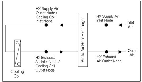
Figure 122. Schematic of the CoilSystem:Cooling:DX:HeatExchangerAssisted compound object
NOTE: Node naming shown in Figure 122 is representative for HeatExchanger:AirToAir:SensibleAndLatent. For HeatExchanger:AirToAir:FlatPlate, the exhaust air nodes are referred to as ‘secondary air’ nodes. For HeatExchanger:Desiccant:BalancedFlow, the supply air nodes are referred to as ‘regeneration air’ nodes and the exhaust air nodes as ‘process air’ nodes.
A unique user-assigned name for the heat exchanger-assisted DX cooling coil. Any reference to this compound component by another object will use this name.
This alpha field denotes the type of heat exchanger being modeled. Valid choices are:
HeatExchanger:AirToAir:FlatPlate
HeatExchanger:AirToAir:SensibleAndLatent
HeatExchanger:Desiccant:BalancedFlow
This alpha field denotes the name of the air-to-air heat exchanger being modeled.
This alpha field denotes the type of DX cooling coil being modeled. The only valid choice is Coil:Cooling:DX:SingleSpeed.
This alpha field denotes the name of the DX cooling coil being modeled.
Following is an example input for this compound object:
CoilSystem:Cooling:DX:HeatExchangerAssisted,
HeatExchangerAssistedCoolingCoil, ! Name of the heat exchanger assisted cooling coil
HeatExchanger:AirToAir:SensibleAndLatent, ! Heat exchanger type
Air to Air Heat Exchanger 1, ! Heat exchanger name
Coil:Cooling:DX:SingleSpeed, ! Cooling coil type
DX Cooling Coil 1; ! Cooling coil name
HeatExchanger:AirToAir:SensibleAndLatent,
Air to Air Heat Exchanger 1, !- Heat exchanger name
FanAndCoilAvailSched, !- Availability schedule name
1.3, !- Nominal supply air flow rate {m3/s}
.2, !- Sensible effectiveness at 100% airflow heating condition
.0, !- Latent effectiveness at 100% airflow heating condition
.23, !- Sensible effectiveness at 75% airflow heating condition
.0, !- Latent effectiveness at 75% airflow heating condition
.2, !- Sensible effectiveness at 100% airflow cooling condition
.0, !- Latent effectiveness at 100% airflow cooling condition
.23, !- Sensible effectiveness at 75% airflow cooling condition
.0, !- Latent effectiveness at 75% airflow cooling condition
HeatExchangerSupplyAirInletNode, !- Supply air inlet node name
DX Cooling Coil Air Inlet Node, !- Supply air outlet node name
HeatExchangerExhaustAirInletNode, !- Exhaust air inlet node name
HeatExchangerExhaustAirOutletNode, !- Exhaust air outlet node name
50.0, !- Nominal electric power {W}
No, !- Supply air outlet temperature control
Rotary, !- Heat exchanger type
None; !- Frost control type
Coil:Cooling:DX:SingleSpeed,
DX Cooling Coil 1, !- Coil Name
FanAndCoilAvailSched, !- Availability Schedule
25000, !- Rated Total Cooling Capacity (gross) {W}
0.75, !- Rated SHR
3.0, !- Rated COP
1.3, !- Rated Air Volume Flow Rate {m3/s}
DX Cooling Coil Air Inlet Node, !- Coil Air Inlet Node
HeatExchangerExhaustAirInletNode, !- Coil Air Outlet Node
ACCoolCapFT, !- Total Cooling Capacity Modifier Curve (function of temperature)
ACCoolCapFFF, !- Total Cooling Capacity Modifier Curve (function of flow fraction)
ACEIRFT, !- Energy Input Ratio Modifier Curve (function of temperature)
ACEIRFFF, !- Energy Input Ratio Modifier Curve (function of flow fraction)
ACPLFFPLR; !- Part Load Fraction Correlation (function of part load ratio)
No variables are reported for this compound object. However, outputs are provided by the cooling coil and heat exchanger that are specified.
|
|
|
|

Figure 123. Schematic of the CoilSystem:Cooling:Water:HeatExchangerAssisted compound object
Note: Node naming shown in Figure 123 is representative for HeatExchanger:AirToAir:SensibleAndLatent. For HeatExchanger:AirToAir:FlatPlate, the exhaust air nodes are referred to as ‘secondary air’ nodes.
This compound object models the basic operation of an air-to-air heat exchanger in conjunction with a chilled-water cooling coil. The heat exchanger-assisted water cooling coil does not have an operating schedule of its own; its operating schedule is governed by the availability schedules for the chilled-water cooling coil and the air-to-air heat exchanger. Heat exchange will occur whenever the heat exchanger is available to operate (via its availability schedule) and a temperature difference exists between the two air streams -- there is currently no method to enable or disable heat exchange based on zone air humidity level. This compound object is used in place of where a chilled-water cooling coil object would normally be used by itself.
To model a heat exchanger-assisted water cooling coil, the input data file should include the following objects:
n CoilSystem:Cooling:Water:HeatExchangerAssisted compound object
n Air-to-air heat exchanger object (HeatExchanger:AirToAir:FlatPlate or HeatExchanger:AirToAir:SensibleAndLatent)
n Chilled-water cooling coil object (Coil:Cooling:Water or Coil:Cooling:Water:DetailedGeometry)
Links to the cooling coil and air-to-air heat exchanger specifications are provided in the input data syntax for this compound object. A description of each input field for this compound object is provided below.
A unique user-assigned name for the heat exchanger-assisted water cooling coil. Any reference to this compound component by another object (e.g., ZoneHVAC:UnitVentilator, ZoneHVAC:FourPipeFanCoil, component in an air loop Branch object) will use this name.
This alpha field denotes the type of heat exchanger being modeled. Valid choices are:
HeatExchanger:AirToAir:FlatPlate
HeatExchanger:AirToAir:SensibleAndLatent
This alpha field denotes the name of the air-to-air heat exchanger being modeled.
This alpha field denotes the type of chilled-water cooling coil being modeled. Valid choices are:
Coil:Cooling:Water
Coil:Cooling:Water:DetailedGeometry
This alpha field denotes the name of the chilled-water cooling coil being modeled.
Following is an example input for this compound object:
CoilSystem:Cooling:Water:HeatExchangerAssisted,
Heat Exchanger Assisted Cooling Coil 1, !- Name of the heat exchanger assisted cooling coil
HeatExchanger:AirToAir:FlatPlate, !- Heat exchanger type
Heat Exchanger Assisting Cooling Coil, !- Heat exchanger name
Coil:Cooling:Water:DetailedGeometry, !- Cooling coil type
Main Cooling Coil 1; !- Cooling coil name
HeatExchanger:AirToAir:FlatPlate,
Heat Exchanger Assisting Cooling Coil, !- Name
CoolingCoilAvailSched, !- Available Schedule
Counter Flow, !- flow arrangement
Yes, !- Economizer lockout
1.0, !- hA ratio
1.32, !- Nominal supply air flow rate {m3/s}
24.0, !- Nominal supply air inlet temperature {C}
21.0, !- Nominal supply air outlet temperature {C}
1.32, !- Nominal secondary air flow rate {m3/s}
12.0, !- Nominal secondary air inlet temperature {C}
100.0, !- Nominal electric power {W}
Mixed Air Node 1, !- Supply air inlet node
Main Cooling Coil 1 Inlet Node, !- Supply air outlet node
Main Cooling Coil 1 Outlet Node, !- Secondary air inlet node
Main Heating Coil 1 Inlet Node; !- Secondary air outlet node
Coil:Cooling:Water:DetailedGeometry,
Main Cooling Coil 1, !- Coil Name
CoolingCoilAvailSched, !- Available Schedule
autosize, !- Max Water Flow Rate of Coil {m3/s}
autosize, !- Tube Outside Surf Area {m2}
autosize, !- Total Tube Inside Area {m2}
autosize, !- Fin Surface Area {m2}
autosize, !- Minimum Air Flow Area {m2}
autosize, !- Coil Depth {m}
autosize, !- Fin Diameter {m}
, !- Fin Thickness {m}
, !- Tube Inside Diameter {m}
, !- Tube Outside Diameter {m}
, !- Tube Thermal Conductivity {W/m-K}
, !- Fin Thermal Conductivity {W/m-K}
, !- Fin Spacing {m}
, !- Tube Depth Spacing {m}
, !- Number of Tube Rows
autosize, !- Number of Tubes per Row
Main Cooling Coil 1 Water Inlet Node, !- Coil_Water_Inlet_Node
Main Cooling Coil 1 Water Outlet Node, !- Coil_Water_Outlet_Node
Main Cooling Coil 1 Inlet Node, !- Coil_Air_Inlet_Node
Main Cooling Coil 1 Outlet Node; !- Coil_Air_Outlet_Node
No variables are reported for this compound object. However, outputs are provided by the cooling coil and heat exchanger that are specified.
EnergyPlus can model a heat pump water heater (HPWH) consisting of a water heater tank (e.g., WaterHeater:Mixed), a direct expansion (DX) “coil” (i.e., an air-to-water DX compression system which includes a water heating coil, air coil, compressor, and water pump), and a fan to provide air flow across the air coil associated with the DX compression system. These objects work together to model a system which heats water using zone air, outdoor air, or a combination of zone and outdoor air as the primary heat source.
The WaterHeater:HeatPump compound object, water heater tank object (e.g., WaterHeater:Mixed), and fan object (e.g., Fan:OnOff) are defined elsewhere in this reference document. Coil:WaterHeating:AirToWaterHeatPump object described here models an air-to-water DX compression system to determine its air-side and water-side performance. This DX coil object calculates the air-side sensible and latent cooling capacity at the specific operating conditions for each simulation timestep, as well as the condenser’s water-side temperature difference at a given condenser water flow rate.
The heat pump water heater DX coil model performs the following major functions:
· calculates the electric consumption of the DX compressor and water pump
· calculates the amount of heat delivered to the water tank
· calculates the electric consumption of the compressor’s crankcase heater
· calculates the air-side performance of the DX coil
The input fields for this object are described below in detail:
This alpha field defines a unique user-assigned name for an instance of a heat pump water heater DX coil. Any reference to this coil by another object (e.g., Heat Pump:Water Heater) will use this name.
This numeric field defines the DX coil heating capacity in Watts at the rated evaporator inlet air temperatures, rated condenser inlet water temperature, rated evaporator air flow rate, and rated condenser water flow rate specified below. Values must be greater than 0. This value represents water heating capacity, and it may or may not include the impact of condenser pump heat (see field Condenser Pump Heat Included in Rated Heating Capacity below).
This numeric field defines the DX coil’s water heating coefficient of performance (COP=water heating capacity in watts divided by electrical power input in watts) at rated conditions (rated inlet temperatures and flow rates specified below). This input not only determines the electric energy use of the heat pump DX coil, but also the amount of total air cooling provided by the evaporator. The rated COP includes compressor power, and may or may not include condenser pump power or evaporator fan power (see field Evaporator Fan Power Included in Rated COP and field Condenser Pump Power Included in Rated COP). Values must be greater than 0. If this field is left blank, the default value is 3.2.
This numeric field defines the air-side sensible heat ratio (SHR=sensible cooling capacity divided by total cooling capacity) of the DX coil at rated conditions (rated inlet temperatures and flow rates specified below). This value should not include the effect of evaporator fan heat. Values must be greater than or equal to 0.5, and less than or equal to 1.0. The default value is 0.85.
This numeric field defines the evaporator inlet air dry-bulb temperature, in degrees Celsius, that corresponds to rated coil performance (heating capacity, COP and SHR). Values must be greater than 5°C. If this field is left blank, the default value is 19.7°C.
This numeric field defines the evaporator inlet air wet-bulb temperature, in degrees Celsius, that corresponds to rated coil performance (heating capacity, COP and SHR). Values must be greater than 5°C. If this field is left blank, the default value is 13.5°C.
This numeric field defines the condenser inlet water temperature, in degrees Celsius, that corresponds to rated coil performance (heating capacity, COP and SHR). Values must be greater than 25°C. If this field is left blank, the default value is 57.5°C.
This numeric field defines the evaporator air volume flow rate in cubic meters per second at rated conditions. Values must be greater than 0. If this field is left blank or autocalculated (field value = autocalculate), the default value is 5.035E-5 m3/s/W (31.25 cfm/MBH) multiplied by the Rated Heating Capacity specified above. When autocalculating the rated evaporator air volumetric flow rate, a zone sizing object is not required.
This numeric field defines the condenser water volumetric flow rate in cubic meters per second at rated conditions. Values must be greater than 0. If this field is left blank or autocalculated (field value = autocalculate), the default value is 4.487E-8 m3/s/W (0.208 gpm/MBH) multiplied by the Rated Heating Capacity specified above. When autocalculating the rated condenser water volumetric flow rate, a zone sizing object is not required. A warning message will be issued if the ratio of Rated Condenser Water Volumetric Flow Rate to Rated Heating Capacity is less than 1.79405E-8 m3/s/W (0.083 gpm/MBH) or greater than 8.97024E-8 m3/s/W (0.417 gpm/MBH), but the simulation will continue.
This choice field specifies if evaporator fan power is included in the rated COP defined above. This input impacts the calculation of compressor electric power and total air cooling provided by the evaporator for each simulation timestep. If Yes is selected, the evaporator fan power is subtracted from the total electric heating power when calculating total evaporator cooling capacity. If No is selected, it is assumed that the total heating power does not include evaporator fan power. If this field is left blank, the default is Yes. See the Engineering Reference section for Coil:WaterHeating:AirToWaterHeatPump for further details.
This choice field specifies if condenser pump power is included in the rated COP defined above. This input impacts the calculation of compressor electric power which then impacts the total air cooling provided by the evaporator for each simulation timestep. If Yes is selected, the condenser pump power is subtracted from the total electric heating power when calculating total evaporator cooling capacity. If No is selected, it is assumed that the total heating power does not include the condenser pump. If this field is left blank, the default is No. See Engineering Reference section for Coil:WaterHeating:AirToWaterHeatPump for further details.
This choice field specifies if condenser pump heat is included in the rated heating capacity and rated COP defined above. This input impacts the calculation of compressor electric power and total air cooling provided by the evaporator for each simulation timestep. If Yes is selected, the condenser pump heat is already included in the rated heating capacity and rated COP. If No is selected, it is assumed that the rated heating capacity and rated COP do not include the condenser pump heat, and pump heat is added to the total water heating capacity based on the Condenser Water Pump Power and Fraction of Condenser Pump Heat to Water fields below. If this field is left blank, the default is No. See Engineering Reference section for Coil:WaterHeating:AirToWaterHeatPump for further details.
This numeric field defines the DX coil’s condenser pump power in Watts. This is the operating pump power as installed. Values must be greater than or equal to 0. If this field is left blank, the default value is 0. A warning message will be issued if the ratio of Condenser Water Pump Power to Rated Heating Capacity exceeds 0.1422 W/W (41.67 Watts/MBH), but the simulation will continue.
This numeric field defines the fraction of condenser pump heat that is transferred to the condenser water. The pump is assumed to be downstream of the condenser water coil, and this field is used to determine the water temperature at the condenser outlet node when the field Condenser Pump Power Included in Rated Heating Capacity is set to No. Values must be greater than or equal to 0 and less than or equal to 1. If this field is left blank, the default value is 0.2.
This alpha field defines the name of the air node from which the evaporator coil draws its inlet air.
This alpha field defines the name of the air node to which the evaporator coil sends its outlet air.
This alpha field defines the name of the node from which the DX coil condenser draws its inlet water. This node name must also match the source side outlet node name for the water heater tank connected to this DX coil (ref: Water Heaters).
This alpha field defines the name of the node to which the heat pump condenser sends it outlet water. This node name must also match the source side inlet node name for the water heater tank connected to this DX coil (ref: Water Heaters).
This numeric field defines the compressor’s crankcase heater capacity in Watts. The crankcase heater only operates when the compressor is off and the air surrounding the compressor is below the Maximum Ambient Temperature for Crankcase Heater Operation specified below.
This numeric field defines the maximum ambient temperature for crankcase heater operation in degree Celsius. The crankcase heater only operates when the air surrounding the compressor is below this maximum temperature value and the compressor is off The ambient temperature surrounding the compressor is set by the Heat Pump:Water Heater parent object (field Compressor Location).
This choice field specifies the air temperature type used for the heating capacity and COP modifier curve objects below. The valid selections are Dry-bulb Temperature and Wet-bulb Temperature. If dry-bulb temperature is selected, the inlet air dry-bulb temperature entering the heat pump DX coil and fan section is used to evaluate the curve objects. If wet-bulb temperature is selected, the inlet air wet-bulb temperature entering the heat pump DX coil and fan section is used to evaluate the curve objects. If this field is left blank and the following curve names are defined, the default value is wet-bulb temperature. If the following curve names are not defined, this field is not used.
This alpha field specifies the name of a biquadratic or cubic performance curve object (ref: Performance Curves) that defines the variation in DX coil heating capacity as a function of inlet fluid (air and water) temperatures. The biquadratic curve uses evaporator inlet air temperature (dry-bulb or wet-bulb temperature based on the field Evaporator Air Temperature Type for Curve Objects defined above) and condenser inlet water temperature as the independent variables. The cubic curve uses evaporator inlet air (dry-bulb or wet-bulb) temperature as the independent variable. The output of this curve is multiplied by the rated heating capacity to give the heating capacity at specific operating conditions (i.e., at temperatures different from the rating point temperatures). The curve should be normalized to have the value of 1.0 at the rating point temperatures. If this field is left blank, the heating capacity remains constant (curve value assumed to be 1.0 for all conditions).
This alpha field specifies the name of a quadratic or cubic performance curve object (ref: Performance Curves) that defines the variation in DX coil heating capacity as a function of the ratio of actual air flow rate across the evaporator coil to the rated evaporator air flow rate. The output of this curve is multiplied by the rated heating capacity and the heating capacity modifier curve (function of temperature) to give the DX coil heating capacity at the specific inlet fluid temperatures and air flow rate at which the coil is operating. The curve should be normalized to have the value of 1.0 at the rated evaporator air flow rate (air flow fraction of 1.0). If this field is left blank, the heating capacity remains constant (curve value assumed to be 1.0 for all air flow rates).
This alpha field specifies the name of a quadratic or cubic performance curve object (ref: Performance Curves) that defines the variation in DX coil heating capacity as a function of the ratio of actual water flow rate through the condenser to the rated condenser water flow rate. The output of this curve is multiplied by the rated heating capacity and the output from the two other heating capacity modifier curves (function of temperature and function of air flow fraction) to give the DX coil heating capacity at the specific inlet fluid temperatures and flow rates at which the coil is operating. The curve should be normalized to have the value of 1.0 at the rated condenser water flow rate (water flow fraction of 1.0). If this field is left blank, the heating capacity remains constant (curve value assumed to be 1.0 for all water flow rates).
This alpha field specifies the name of a biquadratic or cubic performance curve object (ref: Performance Curves) that defines the variation in DX coil heating COP as a function of inlet fluid (air and water) temperatures. The biquadratic curve uses evaporator inlet air temperature (dry-bulb or wet-bulb temperature based on the field Evaporator Air Temperature Type for Curve Objects defined above) and condenser inlet water temperature as the independent variables. The cubic curve uses evaporator inlet air (dry-bulb or wet-bulb) temperature as the independent variable. The output of this curve is multiplied by the rated COP to give the heating COP at specific operating conditions (i.e., at temperatures different from the rating point temperatures). The curve should be normalized to have the value of 1.0 at the rating point temperatures. If this field is left blank, the COP remains constant (curve value assumed to be 1.0 for all conditions).
This alpha field specifies the name of a quadratic or cubic performance curve object (ref: Performance Curves) that defines the variation in DX coil heating COP as a function of the ratio of actual air flow rate across the evaporator coil to the rated evaporator air flow rate. The output of this curve is multiplied by the rated COP and the heating COP modifier curve (function of temperature) to give the heating COP at the specific inlet fluid temperatures and air flow rate at which the coil is operating. The curve should be normalized to have the value of 1.0 at the rated evaporator air flow rate (air flow fraction of 1.0). If this field is left blank, the heating COP remains constant (curve value assumed to be 1.0 for all air flow rates).
This alpha field specifies the name of a quadratic or cubic performance curve object (ref: Performance Curves) that defines the variation in DX coil heating COP as a function of the ratio of actual water flow rate through the condenser to the rated condenser water flow rate.. The output of this curve is multiplied by the rated COP and the output from the two other heating COP modifier curves (function of temperature and function of air flow fraction) to give the DX coil heating COP at the specific inlet fluid temperatures and flow rates at which the coil is operating. The curve should be normalized to have the value of 1.0 at the rated condenser water flow rate (water flow fraction of 1.0). If this field is left blank, the heating COP remains constant (curve value assumed to be 1.0 for all water flow rates).
This alpha field defines the name of a quadratic or cubic performance curve (Ref: Performance Curves) that parameterizes the variation of electrical power input to the DX unit as a function of the part load ratio (PLR, sensible cooling load/steady-state sensible cooling capacity). The product of the rated EIR and EIR modifier curves is divided by the output of this curve to give the “effective” EIR for a given simulation timestep. The part load fraction (PLF) correlation accounts for efficiency losses due to compressor cycling.
The part load fraction correlation should be normalized to a value of 1.0 when the part load ratio equals 1.0 (i.e., no efficiency losses when the compressor(s) run continuously for the simulation timestep). For PLR values between 0 and 1 (0 <= PLR < 1), the following rules apply:
PLF >= 0.7 and PLF >= PLR
If PLF < 0.7 a warning message is issued, the program resets the PLF value to 0.7, and the simulation proceeds. The runtime fraction of the coil is defined as PLR/PLF. If PLF < PLR, then a warning message is issued and the runtime fraction of the coil is limited to 1.0.
A typical part load fraction correlation for a conventional, single-speed DX cooling coil (e.g., residential unit) would be:
PLF = 0.85 + 0.15(PLR)
If the user wishes to model no efficiency degradation due to compressor cycling, the part load fraction correlation should be defined as follows:
PLF = 1.0 + 0.0(PLR)
Following is an example input for the Coil:WaterHeating:AirToWaterHeatPump object.
Coil:WaterHeating:AirToWaterHeatPump,
Zone4HPWHDXCoil, !- Coil Name
4000.0, !- Heating Capacity {W}
3.2, !- Rated COP {W/W}
0.6956, !- Rated SHR (gross)
19.7, !- Rated Evaporator Inlet Air Dry-Bulb Temperature {C}
13.5, !- Rated Evaporator Inlet Air Wet-Bulb Temperature {C}
57.5, !- Rated Condenser Inlet Water Temperature {C}
autocalculate, !- Rated Evaporator Air Volumetric Flow Rate {m3/s}
autocalculate, !- Rated Condenser Water Volumetric Flow Rate {m3/s}
No, !- Evaporator Fan Power Included in Rated COP
No, !- Condenser Pump Power Included in Rated COP
No, !- Condenser Pump Heat Included in Rated Heating Capacity and Rated COP
150.0, !- Condenser Water Pump Power {W}
0.1, !- Fraction of Condenser Pump Heat to Water
Zone4AirOutletNode, !- Evaporator Air Inlet Node Name
Zone4DXCoilAirOutletNode, !- Evaporator Air Outlet Node Name
Zone4WaterInletNode, !- Condenser Water Inlet Node Name
Zone4WaterOutletNode, !- Condenser Water Outlet Node Name
100.0, !- Crankcase Heater Capacity {W}
5.0, !- Maximum Ambient Temperature for Crankcase Heater Operation {C}
wet-bulb temperature, !- Evaporator Air Temperature Type for Curve Objects
HPWHHeatingCapFTemp, !- Heating Capacity Modifier Curve Name (function of temperature)
, !- Heating Capacity Modifier Curve Name (function of air flow fraction)
, !- Heating Capacity Modifier Curve Name (function of water flow fraction)
HPWHHeatingCOPFTemp, !- Heating COP Modifier Curve Name (function of temperature)
, !- Heating COP Modifier Curve Name (function of air flow fraction)
, !- Heating COP Modifier Curve Name (function of water flow fraction)
HPWHPLFFPLR; !- Part Load Fraction Correlation Name (function of part load ratio)
HVAC,Average,DX Coil Total Cooling Rate[W]
HVAC,Sum,DX Coil Total Cooling Energy[J]
HVAC,Average,DX Coil Sensible Cooling Rate[W]
HVAC,Sum,DX Coil Sensible Cooling Energy[J]
HVAC,Average,DX Coil Latent Cooling Rate[W]
HVAC,Sum,DX Coil Latent Cooling Energy[J]
HVAC,Average,DX Cooling Coil Runtime Fraction
HVAC,Average,DX Cooling Coil Crankcase Heater Power[W]
HVAC,Sum,DX Cooling Coil Crankcase Heater Consumption[J]
HVAC,Average,DX Coil Total Water Heating Rate[W]
HVAC,Sum,DX Coil Total Water Heating Energy[J]
HVAC,Average,DX Coil Water Heating Electric Power[W]
HVAC,Sum,DX Coil Water Heating Electric Consumption[J]
This output field is the average total (sensible and latent) cooling rate output of the DX coil in Watts for the timestep being reported. This is determined by the coil inlet and outlet air conditions and the air mass flow rate through the coil.
This output field is the total (sensible plus latent) cooling output of the DX coil in Joules for the timestep being reported. This is determined by the coil inlet and outlet air conditions and the air mass flow rate through the coil.
This output field is the average moist air sensible cooling rate output of the DX coil in Watts for the timestep being reported. This is determined by the inlet and outlet air conditions and the air mass flow rate through the coil.
This output field is the moist air sensible cooling output of the DX coil in Joules for the timestep being reported. This is determined by the inlet and outlet air conditions and the air mass flow rate through the coil.
This output field is the average latent cooling rate output of the DX coil in Watts for the timestep being reported. This is determined by the inlet and outlet air conditions and the air mass flow rate through the coil.
This output field is the latent cooling output of the DX coil in Joules for the timestep being reported. This is determined by the inlet and outlet air conditions and the air mass flow rate through the coil.
This output field is the average runtime fraction of the DX coil compressor for the timestep being reported. This also represents the runtime fraction of the condenser water pump.
This output field is the average electricity consumption rate of the DX coil compressor’s crankcase heater in Watts for the timestep being reported. The crankcase heater operates only when the compressor is off and the air surrounding the compressor is below the Maximum Ambient Temperature for Crankcase Heater Operation, otherwise this report variable is set equal to 0.
This output field is the total electricity consumption of the DX coil compressor’s crankcase heater in Joules for the timestep being reported. This output is also added to a report meter with Resource Type = Electricity, End Use Key = DHW, Group Key = Plant (ref. Report Meter).
This output field is the average water heating rate output of the DX coil (condenser coil plus condenser water pump) in Watts for the timestep being reported. This is determined using the inlet and outlet water temperatures and the water mass flow rate through the condenser coil.
This output field is the total water heating output of the DX coil (condenser coil plus condenser water pump) in Joules for the timestep being reported. This is determined using the inlet and outlet water temperatures and the water mass flow rate through the condenser coil.
This output field is the average electricity consumption rate of the DX coil compressor and condenser pump in Watts for the timestep being reported.
This output field is the electricity consumption of the DX coil compressor and condenser pump in Joules for the timestep being reported. This output is also added to a report meter with Resource Type = Electricity, End Use Key = DHW, Group Key = Plant (ref. Report Meter).
The Coil:Cooling:WaterToAirHeatPump:ParameterEstimation coil is a deterministic model that requires parameters to describe the operating conditions of the heat pump’s components. The parameters are generated from the manufacturer catalog data using multi-variable optimization method. In addition, the cooling coil model can be used for 3 type of compressors: reciprocating, rotary and scroll. Descriptions and strength of each respective model is available in the following references:
Jin, Hui. 2002. Parameter Estimation Based Models of Water Source Heat Pumps. Phd. Thesis, Department of Mechanical and Aerospace Engineering, Oklahoma State University. (downloadable from http://www.hvac.okstate.edu/)
Tang,C. C. 2005. Modeling Packaged Heat Pumps in Quasi-Steady State Energy Simulation Program. M.S. Thesis. Department of Mechanical and Aerospace Engineering, Oklahoma State University. (downloadable from http://www.hvac.okstate.edu/)
This alpha field contains the identifying name for the water-to-air heat pump
Type of compressor mode used for the heat pump. Choices available are reciprocating, rotary and scroll compressor. Note that the parameters vary for different compressor.
This alpha field contains the type of refrigerant used by the heat pump.
This numeric field defines the water flow rate though the coil in m3/sec
This numeric field defines the nominal cooling capacity for the WatertoAirHP cooling coil in Watts.
This numeric field defines the nominal time (in seconds) after startup for condensate to begin leaving the coil's condensate drain line at the coil's rated airflow and temperature conditions, starting with a dry coil. Nominal time is equal to the ratio of the energy of the coil's maximum condensate holding capacity (J) to the coil's steady-state latent capacity (W). Suggested value is 1000; zero value means the latent degradation model is disabled. The default value for this field is zero.
This numeric field defines ratio of the initial moisture evaporation rate from the cooling coil (when the compressor first turns off, in Watts) and the coil's steady-state latent capacity (Watts) at rated airflow and temperature conditions. Suggested value is 1.5; zero value means the latent degradation model is disabled. The default value for this field is zero.
This numeric field defines the compressor’s maximum allowable pressure in Pascal (N/m2)
This numeric field defines the compressor’s minimum allowable pressure in Pascal (N/m2)
This alpha field contains the cooling coil source side inlet node name.
This alpha field contains the cooling coil source side outlet node name.
This alpha field contains the cooling coil air inlet node name.
This alpha field contains the cooling coil air outlet node name.
Depending on the type of compressor and the source side fluid specified, the type of parameters and values also differs. An Excel Spreadsheet is developed to estimate the parameters based on the manufacturer data. The general parameters are listed first followed by specific parameters required by the respective compressor model. Lastly, parameters are listed based on the type of source side fluid used.
This numeric field defines the estimated parameter load side total heat transfer coefficient in W/K. This field was previously known as Parameter 1.
This numeric field defines the estimated parameter load side outside surface heat transfer coefficient in W/K. This field was previously known as Parameter 2.
This numeric field defines the estimated parameter superheat temperature at the evaporator outlet in ˚C. This field was previously known as Parameter 3.
This numeric field defines the estimated parameter compressor power losses, which accounts for the loss of work due to mechanical and electrical losses in the compressor in Watts. This field was previously known as Parameter 4.
This numeric field defines the estimated parameter of the compressor’s efficiency. The compressor efficiency is formulated as the equation below:
![]()
This field was previously know as Parameter 5.
This numeric field defines the estimated parameter piston displacement of the compressor in m3/s. This field was part of what was previously known as Parameter 6. It should be used when the Compressor type is either Reciprocating and Rotary. The field should be left blank when Compressor type is Scroll.
This numeric field defines the estimated parameter pressure drop at the compressor suction and discharge in Pascals (N/m2). This field was part of what was previously known as Parameter 7. It should be used when the Compressor type is either Reciprocating and Rotary. The field should be left blank when Compressor type is Scroll.
This numeric field defines the estimated parameter clearance factor of the compressor. This parameter is dimensionless. This field was part of what was previously known as Parameter 8. It should only be used when the Compressor type is Reciprocating. The field should be left blank when Compressor type is Scroll or Rotary.
This numeric field defines the refrigerant volume flow rate at the beginning of the compression [m3/s]. This field was part of what was previously known as Parameter 6. It should only be used when the Compressor type is Scroll. The field should be left blank when Compressor type is Reciprocating or Rotary.
This numeric field defines the built-in-volume ratio. This field was part of what was previously known as Parameter 7. It should only be used when the Compressor type is Scroll. The field should be left blank when Compressor type is Reciprocating or Rotary.
This numeric field defines the leak rate coefficient for the relationship between pressure ratio and leakage rate. This field was part of what was previously known as Parameter 8. It should only be used when the Compressor type is Scroll. The field should be left blank when Compressor type is Reciprocating or Rotary.
This numeric field defines the estimated parameter source side heat transfer coefficient in W/K. This field was part of what was previously known as Parameter 9. It should only be used when the Source Side Fluid Name is Water.
This numeric field defines the estimated parameter source side heat transfer resistance 1. Unit is dimensionless. This field was part of what was previously known as Parameter 9. It should only be used when the Source Side Fluid Name is an antifreeze.
This numeric field defines the estimated parameter source side heat transfer resistance 2. Unit is W/K. This field was previously known as Parameter 10. It should only be used when the Source Side Fluid Name is an antifreeze.
Following is an example for COIL:WaterToAirHP:ParameterEstimation:Cooling coil input
Coil:Cooling:WaterToAirHeatPump:ParameterEstimation,
Heat Pump Cooling Mode AHU1, !- Name
Scroll, !- Compressor Type
R22, !- Refrigerant Type
0.0015, !- Design Source Side Flow Rate {m3/s}
38000, !- Nominal Cooling Coil Capacity {W}
0, !- Nominal Time for Condensate Removal to Begin {s}
0, !- Ratio of Initial Moisture Evaporation Rate and Steady State Latent Capacity {dimensionless}
3000000, !- High Pressure Cutoff {Pa}
0, !- Low Pressure Cutoff {Pa}
AHU1 Water to Air Heat Pump Source Side1 Inlet Node, !- Water Inlet Node Name
AHU1 Water to Air Heat Pump Source Side1 Outlet Node, !- Water Outlet Node Name
AHU 1 Supply Fan Outlet, !- Air Inlet Node Name
Cooling Coil Air Outlet Node AHU1, !- Air Outlet Node Name
3.78019E+03, !- Load Side Total Heat Transfer Coefficient {W/K}
3.41103E+03, !- Load Side Outside Surface Heat Transfer Coefficient {W/K}
1.57066E+00, !- Superheat Temperature at the Evaporator Outlet {C}
2.23529E+03, !- Compressor Power Losses {W}
1.34624E+00, !- Compressor Efficiency
, !- Compressor Piston Displacement {m3/s}
, !- Compressor Suction/Discharge Pressure Drop {Pa}
, !- Compressor Clearance Factor {dimensionless}
9.74424E-03, !- Refrigerant Volume Flow Rate {m3/s}
2.30803E+00, !- Volume Ratio {dimensionless}
2.06530E-02, !- Leak Rate Coefficient
1.92757E+03, !- Source Side Heat Transfer Coefficient {W/K}
, !- Source Side Heat Transfer Resistance1 {dimensionless}
; !- Source Side Heat Transfer Resistance2 {W/K}
The Coil:Cooling:WaterToAirHeatPump:EquationFit is a simple curve-fit model that requires coefficients generated from the heat pump catalog data. This is an equation-fit model that resembles a black box with no usage of heat transfer equations. The performance of the heat pump is modeled using curves fitted from the catalog data. Description of the equation-fit model is available in the following reference:
Tang,C. C. 2005. Modeling Packaged Heat Pumps in Quasi-Steady State Energy Simulation Program. M.S. Thesis. Department of Mechanical and Aerospace Engineering, Oklahoma State University. (downloadable from http://www.hvac.okstate.edu/)
This alpha field contains the identifying name for the Coil:WatertoAirHPSimple:Cooling
This alpha field contains the cooling coil source side inlet node name.
This alpha field contains the cooling coil source side outlet node name.
This alpha field contains the cooling coil air inlet node name.
This alpha field contains the cooling coil air outlet node name.
This numeric field contains the rated volumetric air flow rate on the load side of the heat pump in m3/s. This field is autosizable.
This numeric field contains the rated volumetric water flow rate on the source side of the heat pump in m3/s. This field is autosizable.
This numeric field contains the rated total cooling capacity of the heat pump in W. This field is autosizable.The rated total cooling capacity should be within 20% of the rated heating capacity, otherwise a warning message is issued.
This numeric field contains the rated sensible capacity of the heat pump in W. This field is autosizable.
This numeric field contains the rated cooling coefficient of performance of the heat pump.
These numeric fields contain the first to fifth coefficient for the heat pump total cooling capacity.
These numeric fields contain the first to sixth coefficient for the heat pump sensible cooling capacity.
These numeric fields contain the first to fifth coefficient for the heat pump power consumption.
This numeric field defines the nominal time (in seconds) after startup for condensate to begin leaving the coil's condensate drain line at the coil's rated airflow and temperature conditions, starting with a dry coil. Nominal time is equal to the ratio of the energy of the coil's maximum condensate holding capacity (J) to the coil's steady-state latent capacity (W). Suggested value is 1000; zero value means the latent degradation model is disabled. The default value for this field is zero.
This numeric field defines ratio of the initial moisture evaporation rate from the cooling coil (when the compressor first turns off, in Watts) and the coil's steady-state latent capacity (Watts) at rated airflow and temperature conditions. Suggested value is 1.5; zero value means the latent degradation model is disabled. The default value for this field is zero.
Following is an example of the input for Coil:WaterToAirHP:EquationFit:Cooling coil
Coil:Cooling:WaterToAirHeatPump:EquationFit,
Heat Pump Cooling Mode,!- Name of Coil
Water to Air Heat Pump Source Side1 Inlet Node,!- Coil Water Inlet Node Name
Water to Air Heat Pump Source Side1 Outlet Node,!- Coil Water Outlet Node Name
Cooling Coil Air Inlet Node,!- Coil Air Inlet Node Name
Heating Coil Air Inlet Node,!- Coil Air Outlet Node Name
4.6015E-01,!- Rated Air Volumetric Flow Rate
2.8391E-04,!- Rated Water Volumetric Flow Rate
23125.59,!- Rated Total Cooling Capacity
16267.05,!- Rated Sensible Cooling Capacity
4.7,!- Rated Cooling Coefficient of Performance
-0.68126221,!- Total Cooling Capacity Coefficient 1
1.99529297,!- Total Cooling Capacity Coefficient 2
-0.93611888,!- Total Cooling Capacity Coefficient 3
0.02081177,!- Total Cooling Capacity Coefficient 4
0.008438868,!- Total Cooling Capacity Coefficient 5
2.24209455,!- Sensible Cooling Capacity Coefficient 1
7.28913391,!- Sensible Cooling Capacity Coefficient 2
-9.06079896,!- Sensible Cooling Capacity Coefficient 3
-0.36729404,!- Sensible Cooling Capacity Coefficient 4
0.218826161,!- Sensible Cooling Capacity Coefficient 5
0.00901534,!- Sensible Cooling Capacity Coefficient 6
-3.20456384,!- Cooling Power Consumption Coefficient 1
0.47656454,!- Cooling Power Consumption Coefficient 2
3.16734236,!- Cooling Power Consumption Coefficient 3
0.10244637,!- Cooling Power Consumption Coefficient 4
-0.038132556,!- Cooling Power Consumption Coefficient 5
0,!- Nominal Time for Condensate Removal to Begin
0;!- Ratio of Initial Moisture Evaporation Rate and Steady-state Latent Capacity
Coil:Cooling:WaterToAirHeatPump:ParameterEstimation and Coil:Cooling:WaterToAirHeatPump:EquationFit have the same output variables listed as follows;
HVAC, Average, WatertoAirHP Power [W]
HVAC, Average, WatertoAirHP Load Side Total Heat Transfer Rate [W]
HVAC, Average, WatertoAirHP Load Side Sensible Heat Transfer Rate [W]
HVAC, Average, WatertoAirHP Source Side Heat Transfer Rate [W]
HVAC, Average, WatertoAirHP Part Load Ratio
HVAC, Average, WatertoAirHP Duty Factor
HVAC, Average, WatertoAirHP Load Side Mass Flow Rate[kg/s]
HVAC, Average, WatertoAirHP Load Side Inlet Dry Bulb Temperature [C]
HVAC, Average, WatertoAirHP Load Side Inlet Humidity Ratio [kg/kg]
HVAC, Average, WatertoAirHP Load Side Outlet Dry Bulb Temperature [C]
HVAC, Average, WatertoAirHP Load Side Outlet Humidity Ratio [kg/kg]
HVAC, Average, WatertoAirHP Source Side Mass Flow Rate[kg/s]
HVAC, Average, WatertoAirHP Source Side Inlet Temperature [C]
HVAC, Average, WatertoAirHP Source Side Outlet Temperature [C]
HVAC, Sum, WatertoAirHP Cooling Electric Consumption [J]
HVAC, Sum, WatertoAirHP Load Side Total Cooling Energy [J]
HVAC, Sum, WatertoAirHP Load Side Sensible Cooling Energy [J]
HVAC, Sum, WatertoAirHP Load Side Latent Cooling Energy [J]
HVAC, Sum, WatertoAirHP Source Side Cooling Energy [J]
This output variable is the average electric consumption rate of the heat pump in Watts over the timestep being reported.
The output variable is the average total cooling load provide by the heat pump which includes the sensible and latent load in Watts over the timestep being reported.
The output variable is the average sensible cooling load provide by the heat pump in Watts over the timestep being reported.
The output variable is the average heat rejected to the water at the heat pump condenser in Watts over the timestep being reported.
This output variable is the ratio of the part-load capacity to the steady state capacity of the WatertoAirHP coil. For the cycling fan mode, the runtime fraction for the heat pump compressor may be different from the compressor part-load ratio reported here due to the part-load performance of the WatertoAirHP coil (delay at start-up to reach steady-state output). In general, runtime fractions are reported by individual components where appropriate.
This output variable is the function of the part load ratio (PLR, part-load capacity/ steady state capacity). The duty factor or part load fraction accounts for efficiency losses due to compressor cycling.
The output variable is the average air mass flow rate going through the heat pump over the timestep being reported.
The output variable is the average entering air dry-bulb temperature over the timestep being reported.
The output variable is the average entering air dry humidity ratio over the timestep being reported.
The output variable is the average leaving air dry-bulb temperature over the timestep being reported.
The output variable is the average leaving air dry humidity ratio over the timestep being reported.
The output variable is the average water mass flow rate going through the heat pump over the timestep being reported.
The output variable is the average entering water temperature over the timestep being reported.
The output variable is the average leaving water temperature over the timestep being reported.
The output variable is the electric consumption of the heat pump in Joules over the timestep being reported. This output is also added to a report meter with Resource Type = Electricity, End Use Key = Cooling, Group Key = System (ref. Report Meter).
The output variable is the total cooling output of the coil in Joules over the timestep being reported. Resource Type = EnergyTransfer, End Use Key = CoolingCoils, Group Key = System (ref. Report Meter).
The output variable is the total sensible cooling output of the coil in Joules over the timestep being reported
The output variable is the total latent cooling output of the coil in Joules over the timestep being reported.
The output variable is the total source side heat transfer of the coil in Joules over the timestep being reported
The Water to Air heat pump heating coil is a deterministic model that requires parameters to describe the operating conditions of the heat pump’s components. The parameters are generated from the manufacturer catalog data using multi-variable optimization method. However, the parameters required for WatertoAirHP heating coil is similar to WatertoAirHP cooling except (source side outside heat transfer coefficient) parameter is not required for heating. In addition, the heating coil model can be used for 3 type of compressors which are reciprocating, rotary and scroll.
This alpha field contains the identifying name for the water-to-air heat pump
Type of compressor mode used for the heat pump. Choices available are reciprocating, rotary and scroll compressor. Note that the parameters vary for different compressor.
This alpha field contains the type of refrigerant used by the heat pump.
This numeric field defines the water flow rate though the coil in m3/sec
This numeric field defines the nominal heating capacity for the WatertoAirHP heating coil in Watts.
This numeric field defines the compressor’s maximum allowable pressure in Pascal (N/m2)
This numeric field defines the compressor’s minimum allowable pressure in Pascal (N/m2)
This alpha field contains the heating coil source side inlet node name.
This alpha field contains the heating coil source side outlet node name.
This alpha field contains the heating coil air inlet node name.
This alpha field contains the heating coil air outlet node name.
Depending on the type of compressor specified, the type of parameters and values also differs. An Excel Spreadsheet is in the final stage of development that is capable of estimating the parameters based on the manufacturer data. The general parameters are listed first followed by specific parameters required by the respective compressor model. Lastly, parameters are listed based on the type of source side fluid used.
This numeric field defines the estimated parameter load side total heat transfer coefficient in W/K. This field was previously known as Parameter 1.
This numeric field defines the estimated parameter superheat temperature at the evaporator outlet in ˚C. This field was previously known as Parameter 2.
This numeric field defines the estimated parameter compressor power losses, which accounts for the loss of work due to mechanical and electrical losses in the compressor in Watts. This field was previously known as Parameter 3.
This numeric field defines the estimated parameter of the compressor’s efficiency. The compressor efficiency is formulated as the equation below:
![]()
This field was previously know as Parameter 4.
This numeric field defines the estimated parameter piston displacement of the compressor in m3/s. This field was part of what was previously known as Parameter 5. It should be used when the Compressor type is either Reciprocating and Rotary. The field should be left blank when Compressor type is Scroll.
This numeric field defines the estimated parameter pressure drop at the compressor suction and discharge in Pascals (N/m2). This field was part of what was previously known as Parameter 6. It should be used when the Compressor type is either Reciprocating and Rotary. The field should be left blank when Compressor type is Scroll.
This numeric field defines the estimated parameter clearance factor of the compressor. This parameter is dimensionless. This field was part of what was previously known as Parameter 7. It should only be used when the Compressor type is Reciprocating. The field should be left blank when Compressor type is Scroll or Rotary.
This numeric field defines the refrigerant volume flow rate at the beginning of the compression [m3/s]. This field was part of what was previously known as Parameter 6. It should only be used when the Compressor type is Scroll. The field should be left blank when Compressor type is Reciprocating or Rotary.
This numeric field defines the built-in-volume ratio. This field was part of what was previously known as Parameter 6. It should only be used when the Compressor type is Scroll. The field should be left blank when Compressor type is Reciprocating or Rotary.
This numeric field defines the coefficient for the relationship between pressure ratio and leakage rate. This field was part of what was previously known as Parameter 7. It should only be used when the Compressor type is Scroll. The field should be left blank when Compressor type is Reciprocating or Rotary.
This numeric field defines the estimated parameter source side heat transfer coefficient in W/K. This field was part of what was previously known as Parameter 8. It should only be used when the Source Side Fluid Name is Water.
This numeric field defines the estimated parameter source side heat transfer resistance 1. Unit is dimensionless. This field was part of what was previously known as Parameter 8. It should only be used when the Source Side Fluid Name is an antifreeze.
This numeric field defines the estimated parameter source side heat transfer resistance 2. Unit is W/K. This field was previously known as Parameter 9. It should only be used when the Source Side Fluid Name is an antifreeze.
Following is an example input for Coil:WatertoAirHP:ParameterEstimation:Heating
Coil:Heating:WaterToAirHeatPump:ParameterEstimation,
Heat Pump HEATING Mode AHU1, !- Name
Scroll, !- Compressor Type
R22, !- Refrigerant Type
0.0015, !- Design Source Side Flow Rate {m3/s}
38000, !- Nominal Heating Coil Capacity {W}
3000000, !- High Pressure Cutoff
0, !- Low Pressure Cutoff {Pa}
AHU1 Water to Air Heat Pump Source Side2 Inlet Node, !- Water Inlet Node Name
AHU1 Water to Air Heat Pump Source Side2 Outlet Node, !- Water Outlet Node Name
Cooling Coil Air Outlet Node AHU1, !- Air Inlet Node Name
Heating Coil Air Outlet Node AHU1, !- Air Outlet Node Name
5.79505E+03, !- Load Side Total Heat Transfer Coefficient {W/K}
1.56696E+00, !- Superheat Temperature at the Evaporator Outlet {C}
3.91338E+03, !- Compressor Power Losses {W}
1.26356E+00, !- Compressor Efficiency
, !- Compressor Piston Displacement {m3/s}
, !- Compressor Suction/Discharge Pressure Drop {Pa}
, !- Compressor Clearance Factor {dimensionless}
6.99573E-03, !- Refrigerant Volume Flow Rate {m3/s}
4.96167E+00, !- Volume Ratio {dimensionless}
2.07750E-06, !- Leak Rate Coefficient {dimensionless}
4.00322E+03, !- Source Side Heat Transfer Coefficient {W/K}
, !- Source Side Heat Transfer Resistance1 {dimensionless}
; !- Source Side Heat Transfer Resistance2 {W/K}
The Water to Air Heating Equation Fit Coil is a simple curve-fit model that requires coefficients generated from the heat pump catalog data. This is an equation-fit model that resembles a black box with no usage of heat transfer equations. The performance of the heat pump is modeled using curves fitted from the catalog data.
This alpha field contains the identifying name for the Coil:WatertoAirHP:EquationFit:Heating
This alpha field contains the heating coil source side inlet node name.
This alpha field contains the heating coil source side outlet node name.
This alpha field contains the heating coil air inlet node name.
This alpha field contains the heating coil air outlet node name.
This numeric field contains the rated volumetric air flow rate on the load side of the heat pump in m3/s. This field is autosizable.
This numeric field contains the rated volumetric water flow rate on the source side of the heat pump in m3/s. This field is autosizable.
This numeric field contains the rated heating capacity of the heat pump in W. This field is autosizable.
This numeric field contains the rated heating coefficient of performance of the heat pump.
These numeric fields contain the first to fifth coefficient for the heat pump capacity.
These numeric fields contain the first to fifth coefficient for the heat pump power consumption.
Coil:Heating:WaterToAirHeatPump:ParameterEstimation and Coil:Heating:WaterToAirHeatPump:EquationFit have the same output variables listed as follows;
HVAC, Average, WatertoAirHP Power [W]
HVAC, Average, WatertoAirHP Load Side Total Heat Transfer Rate [W]
HVAC, Average, WatertoAirHP Load Side Sensible Heat Transfer Rate [W]
HVAC, Average, WatertoAirHP Source Side Heat Transfer Rate [W]
HVAC, Average, WatertoAirHP Part Load Ratio
HVAC, Average, WatertoAirHP Duty Factor
HVAC, Average, WatertoAirHP Load Side Mass Flow Rate[kg/s]
HVAC, Average, WatertoAirHP Load Side Inlet Dry Bulb Temperature [C]
HVAC, Average, WatertoAirHP Load Side Inlet Humidity Ratio [kg/kg]
HVAC, Average, WatertoAirHP Load Side Outlet Dry Bulb Temperature [C]
HVAC, Average, WatertoAirHP Load Side Outlet Humidity Ratio [kg/kg]
HVAC, Average, WatertoAirHP Source Side Mass Flow Rate[kg/s]
HVAC, Average, WatertoAirHP Source Side Inlet Temperature [C]
HVAC, Average, WatertoAirHP Source Side Outlet Temperature [C]
HVAC, Sum, WatertoAirHP Heating Electric Consumption [J]
HVAC, Sum, WatertoAirHP Load Side Total Heating Energy [J]
HVAC, Sum, WatertoAirHP Source Side Heating Energy [J]
This output variable is the average electric consumption rate of the heat pump in Watts over the timestep being reported.
The output variable is the average total heating capacity provide by the heat pump which includes the sensible and latent capacity in Watts over the timestep being reported.
The output variable is the average sensible heating capacity provide by the heat pump in Watts over the timestep being reported. For heating mode, the sensible capacity is equal to the total capacity.
The output variable is the average heat absorbed at the heat pump evaporator in Watts over the timestep being reported.
This output variable is the ratio of the part-load capacity to the steady state capacity of the WatertoAirHP coil. For the cycling fan mode, the runtime fraction for the heat pump compressor may be different from the compressor part-load ratio reported here due to the part-load performance of the WatertoAirHP coil (delay at start-up to reach steady-state output). In general, runtime fractions are reported by individual components where appropriate.
This output variable is the function of the part load ratio (PLR, part-load capacity/ steady state capacity). The duty factor or part load fraction accounts for efficiency losses due to compressor cycling.
The output variable is the average air mass flow rate going through the heat pump over the timestep being reported.
The output variable is the average entering air dry-bulb temperature over the timestep being reported.
The output variable is the average entering air dry humidity ratio over the timestep being reported.
The output variable is the average leaving air dry-bulb temperature over the timestep being reported.
The output variable is the average leaving air dry humidity ratio over the timestep being reported.
The output variable is the average water mass flow rate going through the heat pump over the timestep being reported.
The output variable is the average entering water temperature over the timestep being reported.
The output variable is the average leaving water temperature over the timestep being reported.
The output variable is the total electric consumption of the heat pump in Joules over the timestep being reported. This output is also added to a report meter with Resource Type = Electricity, End Use Key = Heating, Group Key = System (ref. Report Meter).
The output variable is the total cooling output of the coil in Joules over the timestep being reported. Resource Type = EnergyTransfer, End Use Key = HeatingCoils, Group Key = System (ref. Report Meter).
The output variable is the total source side heat transfer of the coil in Joules over the timestep being reported
The following fans may be defined either in the air loop or as a zone equipment component: Fan:ConstantVolume, Fan:OnOff, Fan:VariableVolume, Fan:ZoneExhaust, and FanPerformance:NightVentilation. The data that are common to these fan types include an identifying name, an availability schedule name, a total efficiency rating, a rated pressure rise, and inlet and outlet air node names. In the case of a variable volume fan, additional input includes parameters for modeling fan performance over a range of fan speeds. See the engineering documentation for the variable speed fan for a further description of what these coefficients represent. Commonly-used values for different variable volume systems are shown in the following table.
Table 29. Fan Coefficient Values
|
Type of Fan |
Fan Coeff. 1 |
Fan Coeff. 2 |
Fan Coeff. 3 |
Fan Coeff. 4 |
Fan Coeff. 5 |
|
Inlet Vane Dampers |
0.35071223 |
0.30850535 |
-0.54137364 |
0.87198823 |
0.000 |
|
Discharge Dampers |
0.37073425 |
0.97250253 |
-0.34240761 |
0.000 |
0.000 |
|
Var. Speed Motor |
0.0015302446 |
0.0052080574 |
1.1086242 |
-0.11635563 |
0.000 |
This object models a constant air volume fan that is intended to operate continuously based on a time schedule. This fan will not cycle on and off based on cooling/heating load or other control signals (Ref: Fan:OnOff).
A unique user-assigned name for an instance of a Fan:ConstantVolume. Any reference to this fan by another object will use this name.
The name of the schedule (ref: Schedule) that denotes whether the fan can run during a given hour. A schedule value greater than 0 (usually 1 is used) indicates that the fan can be on during the hour. A value less than or equal to 0 (usually 0 is used) denotes that the fan must be off for the hour. Applicable availability managers (ref. AvailabilityManagerAssignmentList) may override this schedule by forcing the fan to be on or off.
The ratio of the power delivered to the fluid to the electrical input power. It is the product of the motor efficiency and the fan efficiency. The motor efficiency is the power delivered to the shaft divided by the electrical power input to the motor. The fan efficiency is power delivered to the fluid (air) divided by the shaft power. The power delivered to the fluid is the mass flow rate of the air multiplied by the pressure rise divided by the air density. Must be between 0 and 1.
The pressure rise in Pascals at full flow and standard (sea level) conditions (20°C and 101325 Pa).
The full load air volumetric flow rate (m3/sec) at standard temperature and pressure (dry air at 20°C drybulb). The program does use local barometric pressure to account for altitude using equation for "standard atmospheric" pressure on p 6.1 of the ASHRAE 1997 HOF (SI edition) to initialize the air systems being simulated.
p=101325*(1-2.25577E-05*Z)**5.2559
where p=pressure in Pa and Z=altitude in m
The shaft power divided by the electrical power consumed. Must be between 0 and 1.
The fraction of the motor heat that is added to the air stream. A value of 0 means that the motor is completely outside the air stream. A value of 1 means that all of the motor heat loss will go into the air stream and act to cause a temperature rise. Must be between 0 and 1.
The name of the HVAC system node which supplies the inlet air conditions to the fan.
The name of the HVAC system node to which the fan sends its outlet air.
Allows you to specify a user-defined end-use subcategory, e.g., "Central System", etc. A new meter for reporting is created for each unique subcategory (ref: Report Meter). Subcategories are also reported in the ABUPS table. If this field is omitted or blank, the fan will be assigned to the "General" end-use subcategory.
HVAC,Average,Fan Electric Power[W]
HVAC,Average,Fan Delta Temp[C]
HVAC,Sum,Fan Electric Consumption[J]
This output field contains the average electricity consumption rate for the fan in Watts for the timestep being reported.
This output field contains the average rise in air temperature across the fan (outlet air temperature minus inlet air temperature) in degrees Celsius for the timestep being reported.
This output field contains the electricity consumption of the fan in Joules for the timestep being reported. This output is also added to a report meter with Resource Type = Electricity, End Use Key= Fans, Group Key= System (ref. Report Meter).
This object models a constant air volume fan that is intended to cycle on and off in tandem with a cooling or heating system (i.e., AUTO fan control mode). The fan can also operate continuously like Fan:ConstantVolume. If modeling continuous operation and this object is used as part of a system that utilizes Coil:Heating:Gas, Coil:Cooling:DX:SingleSpeed or Coil:Heating:DX:SingleSpeed, the user should confirm proper air flow rates (coil and fan max flows are equal) and that the coil part-load fraction correlation(s) are appropriate (e.g., part-load fraction is less than or equal to 1 for all values of coil part-load ratio). If modeling multi-speed fan operation, this object must be used as part of a compound object that allows multiple fan speeds (e.g., AirLoopHVAC:Unitary:Furnace:HeatCool, ZoneHVAC:PackagedTerminalAirConditioner, etc.). In this case, the ratio of the compound object air flow rate to the fan’s maximum air flow rate is used to determine the power at alternate fan speeds. The optional input for Fan Power Ratio Function of Speed Ratio Curve Name must be entered to model multi-speed fan operation. An optional fan total efficiency ratio curve is also available to model efficiency differences at alternate fan speeds.
A unique user-assigned name for an instance of a Fan:OnOff. Any reference to this fan by another object will use this name.
The name of the schedule (ref: Schedule) that denotes whether the fan can run during a given hour. A schedule value greater than 0 (usually 1 is used) indicates that the fan can be on during the hour. A value less than or equal to 0 (usually 0 is used) denotes that the fan must be off for the hour. Applicable availability managers (ref. AvailabilityManagerAssignmentList) may override this schedule by forcing the fan to be on or off.
The ratio of the power delivered to the fluid to the electrical input power. It is the product of the motor efficiency and the fan efficiency. The motor efficiency is the power delivered to the shaft divided by the electrical power input to the motor. The fan efficiency is power delivered to the fluid (air) divided by the shaft power. The power delivered to the fluid is the mass flow rate of the air multiplied by the pressure rise divided by the air density. Must be between 0 and 1.
The pressure rise in Pascals at full flow and standard (sea level) conditions (20°C and 101325 Pa).
The full load air volumetric flow rate (m3/sec) at standard temperature and pressure (dry air at 20°C drybulb). The program does use local barometric pressure to account for altitude using equation for "standard atmospheric" pressure on p 6.1 of the ASHRAE 1997 HOF (SI edition) to initialize the air systems being simulated.
p=101325*(1-2.25577E-05*Z)**5.2559
where p=pressure in Pa and Z=altitude in m
The shaft power divided by the electrical power consumed. Must be between 0 and 1.
The fraction of the motor heat that is added to the air stream. A value of 0 means that the motor is completely outside the air stream. A value of 1 means that all of the motor heat loss will go into the air stream and act to cause a temperature rise. Must be between 0 and 1.
The name of the HVAC system node which supplies the inlet air conditions to the fan.
The name of the HVAC system node to which the fan sends its outlet air.
Enter the name of an exponent performance curve. This optional alpha field must be used to simulate multi-speed fan motors. This curve represents the ratio of actual fan power to rated fan power when a change in fan speed occurs. Leave this field blank when simulating constant-speed fan motors.
Enter the name of a quadratic or cubic performance curve. This optional alpha field is used to simulate multi-speed fan motors. This curve represents the ratio of actual fan total efficiency to rated fan total efficiency when a change in fan speed occurs. Leave this field blank when simulating constant-speed fan motors.
Allows you to specify a user-defined end-use subcategory, e.g., "Main Fans", etc. A new meter for reporting is created for each unique subcategory (ref: Report Meter). Subcategories are also reported in the ABUPS table. If this field is omitted or blank, the fan will be assigned to the "General" end-use subcategory.
Following is an example input for an OnOff Fan.
Fan:OnOff,
Supply Fan 1, ! Fan Name
FanAndCoilAvailSched, ! Fan Schedule
0.7, ! Fan Efficiency
600.0, ! Delta Pressure [N/M^2]
1.3, ! Max Flow Rate [m^3/Sec]
0.9, ! Motor Efficiency
1.0, ! Motor in Airstream Fraction (1.0 means motor in air stream)
Air Loop Inlet Node, Cooling Coil Air Inlet Node; !Inlet Node, Outlet Node
HVAC,Average,Fan Electric Power[W]
HVAC,Average,Fan Delta Temp[C]
HVAC,Sum,Fan Electric Consumption[J]
HVAC,Average,On/Off Fan Runtime Fraction
This output field contains the average electricity consumption rate for the fan in Watts for the timestep being reported.
This output field contains the average rise in air temperature across the fan (outlet air temperature minus inlet air temperature) in degrees Celsius for the timestep being reported.
This output field contains the electricity consumption of the fan in Joules for the timestep being reported. This output is also added to a report meter with Resource Type = Electricity, End Use Key= Fans, Group Key= System (ref. Report Meter).
This output field contains the fraction of time that this fan operated for the timestep being reported.
A unique user-assigned name for an instance of a Fan:VariableVolume. Any reference to this fan by another object will use this name.
The name of the schedule (ref: Schedule) that denotes whether the fan can run during a given hour. A schedule value greater than 0 (usually 1 is used) indicates that the fan can be on during the hour. A value less than or equal to 0 (usually 0 is used) denotes that the fan must be off for the hour. Applicable availability managers (ref. AvailabilityManagerAssignmentList) may override this schedule by forcing the fan to be on or off.
The ratio of the power delivered to the fluid to the electrical input power at maximum flow. It is the product of the motor efficiency and the fan efficiency. The motor efficiency is the power delivered to the shaft divided by the electrical power input to the motor. The fan efficiency is power delivered to the fluid (air) divided by the shaft power. The power delivered to the fluid is the mass flow rate of the air multiplied by the pressure rise divided by the air density. Must be between 0 and 1.
The pressure rise in Pascals at full flow and standard (sea level) conditions (20°C and 101325 Pa).
The full load air volumetric flow rate (m3/sec) at standard temperature and pressure (dry air at 20°C drybulb). The program does use local barometric pressure to account for altitude using equation for "standard atmospheric" pressure on p 6.1 of the ASHRAE 1997 HOF (SI edition) to initialize the air systems being simulated.
p=101325*(1-2.25577E-05*Z)**5.2559
where p=pressure in Pa and Z=altitude in m
This field is a key/choice field that tells which of the next two fields is filled and is descriptive of how the minimum flow rate is specified for calculating the fan power. The key/choices are:
n Fraction
With this choice, the fan power will be calculated using the value specified in the Fan Power Minimum Flow Fraction field. (The Fan Power Minimum Flow Fraction field should be filled.)
n FixedFlowRate
With this choice, the fan power will be calculated using the value specified in the Fan Power Minimum Air Flow Rate field. (The Fan Power Minimum Air Flow Rate field should be filled.)
The minimum air volumetric flow rate for fan power, specified as a fraction of maximum system air flow rate. Must be between 0 and 1. Note that this field is only used to calculate the fan power. This field does not enforce the system air flow rate during simulation.
The minimum air volumetric flow rate for fan power, specified as a constant minimum air flow rate (m3/sec). Note that this field is only used to calculate the fan power. This field does not enforce the system air flow rate during simulation.
The shaft power divided by the electrical power consumed. Must be between 0 and 1.
The fraction of the motor heat that is added to the air stream. A value of 0 means that the motor is completely outside the air stream. A value of 1 means that all of the motor heat loss will go into the air stream and act to cause a temperature rise. Must be between 0 and 1.
The constant coefficient (C1) in a fourth order polynomial curve giving the fraction of full load power (PLF) as a function of flow fraction (FF). Flow fraction is the air mass flow rate divided by the maximum air mass flow rate. The curve is:
PLF = C1 + C2. FF + C3. FF2 + C4. FF3 + C5. FF4
The linear coefficient (C2) in a fourth order polynomial curve giving the fraction of full load power (PLF) as a function of flow fraction (FF). Flow fraction is the air mass flow rate divided by the maximum air mass flow rate. The curve is:
PLF = C1 + C2. FF + C3. FF2 + C4. FF3 + C5. FF4
The quadratic coefficient (C3) in a fourth order polynomial curve giving the fraction of full load power (PLF) as a function of flow fraction (FF). Flow fraction is the air mass flow rate divided by the maximum air mass flow rate. The curve is:
PLF = C1 + C2. FF + C3. FF2 + C4. FF3 + C5. FF4
The cubic coefficient (C1) in a fourth order polynomial curve giving the fraction of full load power (PLF) as a function of flow fraction (FF). Flow fraction is the air mass flow rate divided by the maximum air mass flow rate. The curve is:
PLF = C1 + C2. FF + C3. FF2 + C4. FF3 + C5. FF4
The coefficient C5 in a fourth order polynomial curve giving the fraction of full load power (PLF) as a function of flow fraction (FF). Flow fraction is the air mass flow rate divided by the maximum air mass flow rate. The curve is:
PLF = C1 + C2. FF + C3. FF2 + C4. FF3 + C5. FF4
The name of the HVAC system node which supplies the inlet air conditions to the fan.
The name of the HVAC system node to which the fan sends its outlet air.
Allows you to specify a user-defined end-use subcategory, e.g., "Central System", etc. A new meter for reporting is created for each unique subcategory (ref: Report Meter). Subcategories are also reported in the ABUPS table. If this field is omitted or blank, the fan will be assigned to the "General" end-use subcategory.
HVAC,Average,Fan Electric Power[W]
HVAC,Average,Fan Delta Temp[C]
HVAC,Sum,Fan Electric Consumption[J]
This output field contains the average electricity consumption rate for the fan in Watts for the timestep being reported.
This output field contains the average rise in air temperature across the fan (outlet air temperature minus inlet air temperature) in degrees Celsius for the timestep being reported.
This output field contains the electricity consumption of the fan in Joules for the timestep being reported. This output is also added to a report meter with Resource Type = Electricity, End Use Key= Fans, Group Key= System (ref. Report Meter).
A unique user-assigned name for an instance of a Fan:ZoneExhaust. Any reference to this fan by another object will use this name.
The name of the schedule (ref: Schedule) that denotes whether the fan can run during a given hour. A schedule value greater than 0 (usually 1 is used) indicates that the fan can be on during the hour. A value less than or equal to 0 (usually 0 is used) denotes that the fan must be off for the hour. Applicable availability managers (ref. AvailabilityManagerAssignmentList) may override this schedule by forcing the fan to be on or off.
The ratio of the power delivered to the fluid to the electrical input power at maximum flow. It is the product of the motor efficiency and the fan efficiency. The motor efficiency is the power delivered to the shaft divided by the electrical power input to the motor. The fan efficiency is power delivered to the fluid (air) divided by the shaft power. The power delivered to the fluid is the mass flow rate of the air multiplied by the pressure rise divided by the air density. Must be between 0 and 1.
The pressure rise in Pascals at full flow and standard (sea level) conditions (20°C and 101325 Pa).
The full load air volumetric flow rate (m3/sec) at standard temperature and pressure (dry air at 20°C drybulb). The program does use local barometric pressure to account for altitude using equation for "standard atmospheric" pressure on p 6.1 of the ASHRAE 1997 HOF (SI edition) to initialize the air systems being simulated.
p=101325*(1-2.25577E-05*Z)**5.2559
where p=pressure in Pa and Z=altitude in m
The name of the HVAC system node which supplies the inlet air conditions to the fan.
The name of the HVAC system node to which the fan sends its outlet air.
Allows you to specify a user-defined end-use subcategory, e.g., "Kitchen Exhaust", "Fume Hoods", etc. A new meter for reporting is created for each unique subcategory (ref: Report Meter). Subcategories are also reported in the ABUPS table. If this field is omitted or blank, the fan will be assigned to the "General" end-use subcategory.
HVAC,Average,Fan Electric Power[W]
HVAC,Average,Fan Delta Temp[C]
HVAC,Sum,Fan Electric Consumption[J]
This output field contains the average electricity consumption rate for the fan in Watts for the timestep being reported.
This output field contains the average rise in air temperature across the fan (outlet air temperature minus inlet air temperature) in degrees Celsius for the timestep being reported.
This output field contains the electricity consumption of the fan in Joules for the timestep being reported. This output is also added to a report meter with Resource Type = Electricity, End Use Key= Fans, Group Key= System (ref. Report Meter).
Examples of Fan:ConstantVolume, Fan:VariableVolume, Fan:ZoneExhaust, and , Fan:OnOff, fans in an IDF are:
Fan:ConstantVolume,
Supply Fan 1, !- Name
FanAndCoilAvailSched, !- Availability Schedule Name
0.7, !- Fan Efficiency
600.0, !- Pressure Rise {Pa}
1.3, !- Maximum Flow Rate {m3/sec}
0.9, !- Motor Efficiency
1.0, !- Motor in Airstream Fraction
Air Loop Inlet Node, Cooling Coil Air Inlet Node; !- Air Inlet Node Name, Air Outlet Node Name
Fan:VariableVolume,
Var Vol Supply Fan 1, !- Name
FanAndCoilAvailSched, !- Availability Schedule Name
0.7, !- Fan Efficiency
600.0, !- Pressure Rise {Pa}
1.3, !- Maximum Flow Rate {m3/s}
0.20, !- Minimum Flow Rate {m3/s}
0.9, !- Motor Efficiency
1.0, !- Motor in Airstream Fraction
0.35071223, !- Fan Coefficient 1
0.30850535, !- Fan Coefficient 2
-0.54137364, !- Fan Coefficient 3
0.87198823, !- Fan Coefficient 4
0.000, !- Fan Coefficient 5
Air Loop Inlet Node, Cooling Coil Air Inlet Node; !- Air Inlet Node Name, Air Outlet Node Name
Fan:ZoneExhaust,
Zone 2 Exhaust Fan, !- Name
FanAndCoilAvailSched, !- Availability Schedule Name
0.6, !- Fan Efficiency
125, !- Pressure Rise {Pa}
0.1, !- Maximum Flow Rate {m3/s}
Zone 2 Exhaust Node, !- Air Inlet Node Name
Zone 2 Exhaust Fan Outlet Node, !- Air Outlet Node Name
Kitchen Exhaust; !- End-Use Subcategory
Fan:OnOff,
AHU 1 Supply Fan, !- Name
FanAvailSched, !- Availability Schedule Name
0.7, !- Fan Efficiency
600.0, !- Pressure Rise {Pa}
2.0, !- Maximum Flow Rate {m3/s}
0.9, !- Motor Efficiency
1.0, !- Motor in Airstream Fraction
AHU 1 Air Loop Inlet, !- Air Inlet Node Name
AHU 1 Supply Fan Outlet; !- Air Outlet Node Name
This object is used for specifying an alternate set of performance parameters for a fan. These alternate parameters are used when a system manager (such as AvailabilityManager:NightVentilation) sets a specified flow rate for a central forced air system. At this time, it can be used with Fan:ConstantVolume, Fan:VariableVolume, Fan:ZoneExhaust, and , Fan:OnOff fans, but not with Fan:ComponentModel fans. The fan model checks whether a fixed flow rate has been set; if it has the fan model will use these alternate performance parameters. Note that it is assumed that the fan will run at a fixed speed in the alternate mode. The inputs needed by this object are the fan name, fan total efficiency, pressure rise, flow rate, motor efficiency, and motor in airstream fraction.
This is the name of a fan defined elsewhere in the input file. The night vent performance parameters will be applied to the named fan when a system manager has set the air system flow rate.
The power delivered to the fluid divided by the electrical input power. It is the product of the motor efficiency and the fan efficiency. The motor efficiency is the power delivered to the shaft divided by the electrical power input to the motor. The fan efficiency is power delivered to the fluid (air) divided by the shaft power. The power delivered to the fluid is the mass flow rate of the air multiplied by the pressure rise divided by the air density. Must be between 0 and 1.
The pressure rise in Pascals at full flow and standard (sea level) conditions (20°C and 101325 Pa).
The design volumetric flow rate of the fan (m3/sec) at standard conditions. This input is not currently used by the night ventilation manager. The flow rate during night ventilation is specified using the SystemAvailabilityManager:NightVentilation "Night Venting Flow Fraction" field. This fraction is multiplied times the fan object's design flow rate.
The shaft power divided by the electrical power consumed. Must be between 0 and 1.
The fraction of the motor heat that is added to the air stream. A value of 0 means that the motor is completely outside the air stream. A value of 1 means that all of the motor heat loss will go into the air stream and act to cause a temperature rise. Must be between 0 and 1.
An example of use in an IDF:
Fan:VariableVolume,
Supply Fan 1, !- Name
FanAvailSched, !- Availability Schedule Name
0.7, !- Fan Efficiency
600.0, !- Pressure Rise {Pa}
autosize, !- Maximum Flow Rate {m3/s}
autosize, !- Minimum Flow Rate {m3/s}
0.9, !- Motor Efficiency
1.0, !- Motor In Airstream Fraction
0.35071223, !- Fan Coefficient 1
0.30850535, !- Fan Coefficient 2
-0.54137364, !- Fan Coefficient 3
0.87198823, !- Fan Coefficient 4
0.000, !- Fan Coefficient 5
Main Heating Coil 1 Outlet Node, !- Air Inlet Node Name
VAV Sys 1 Outlet Node; !- Air Outlet Node Name
FanPerformance:NightVentilation,
Supply Fan 1, !- Fan Name
0.7, !- Fan Efficiency
67.0, !- Pressure Rise {Pa}
autosize, !- Maximum Flow Rate {m3/s}
0.9, !- Motor Efficiency
1.0; !- Motor in Airstream Fraction
The Fan:ComponentModel fan is a more detailed fan type that can be defined in the air loop for central constant-air-volume (CAV) and variable-air-volume (VAV) systems. It includes inputs that describe the air-distribution system as well as the fan, its drive belt (if used), its motor, and its variable-frequency-drive (if used). See the engineering documentation for further descriptions about the inputs for this fan type.
The required unique user-assigned alpha name for an instance of a Fan:ComponentModel. Any reference to this fan by another object will use this name.
The required alpha name of the HVAC system node which supplies the inlet air conditions to the fan.
The required alpha name of the HVAC system node to which the fan sends its outlet air.
The required alpha name of the schedule (ref: Schedule) that denotes whether the fan can run during a given hour. A schedule value greater than 0 (usually 1 is used) indicates that the fan can be on during the hour. A value less than or equal to 0 (usually 0 is used) denotes that the fan must be off for the hour. Applicable availability managers (ref. AvailabilityManagerAssignmentList) may override this schedule by forcing the fan to be on or off.
The full-load volumetric airflow (m3/sec) through the fan at standard temperature and pressure (dry air at 20°C dry-bulb). To initialize the air systems being simulated, the program uses local barometric pressure adjusted for altitude, based on the equation for "standard atmospheric" pressure on p.6.1 of the 1997 ASHRAE Handbook of Fundamentals (SI edition):
p=101325 * (1 - 2.25577E-05 * Z)**5.2559
where p = pressure in Pa and Z = altitude in m. Can be autosized.
Specified or autosized maximum airflow rate (including effects of scaling by Field: Fan Sizing Factor) along with corresponding fan static pressure rise and fan shaft power are reported in the .eio file as, respectively, Design Fan Airflow [m3/s], Design Fan Static Pressure Rise [Pa], and Design Fan Shaft Power [W].
The minimum volumetric airflow (m3/sec) through the fan at standard temperature and pressure (see Maximum Flow Rate field above for condition details). Can be autosized.
The numeric dimensionless factor (Ffan) used to multiply the specified or autosized full-load volumetric airflow (see Maximum Flow Rate field above for details) for fan sizing. If specified, minimum value is 1.0. Default is 1.0 if field is blank.
The required numeric outer diameter of the fan wheel (Dfan, m). This value is determined from manufacturer’s data. In general, larger diameter fans have higher maximum efficiency than smaller diameter fans of the same type (Ref: AMCA Standard 205-10: Energy Efficiency Classification for Fans). Must be greater than zero.
The required numeric outlet area of the fan (Afan,out, m2). This value is determined from manufacturer’s data. It is used to convert fan total pressure rise to fan static pressure rise. Fan static pressure rise is the fan total pressure rise minus the fan outlet velocity pressure; it is not the difference between fan outlet and inlet static pressures (Ref: ANSI/AMCA Standard 210-07, ANSI/ASHRAE Standard 51-07: Laboratory Methods of Testing Fans for Certified Aerodynamic Performance Rating). Must be greater than zero.
The required numeric maximum ratio (ηfan,max) between the power delivered to the air (Hair, W) and the fan shaft input power (Hfan, W). For this parameter, Hair is the volumetric airflow through the fan multiplied by the fan static pressure rise. Maximum fan static efficiency is determined from analyses of manufacturer’s data using:

where ΔPfan is fan static pressure rise (Pa) and Qfan is airflow through the fan (m3/sec). Typically, “do not select” curves on fan performance maps of pressure rise versus flow correspond to or are near maximum efficiency. Must be greater than zero and less than or equal to 1.0.
Calculated fan static efficiency at design flow condition (including part-load effects of oversized fan) is reported in the .eio file as Design Fan Efficiency [-].
The required numeric Euler number (Eumax), which is also called the throttling or pressure coefficient, and is the ratio of pressure forces to inertial forces. The Euler number is determined from analyses of manufacturer’s data using:

where ΔPfan is fan static pressure rise (Pa; see Fan Pressure Rise Curve Name field), Dfan is wheel diameter (m), ρ is the manufacturer’s reference air density (kg/m3), and Qfan is airflow through the fan (m3/sec). Eumax is calculated using any pair of pressure rise and airflow values that correspond with maximum fan static efficiency for the specified fan. Must be greater than zero.
The required numeric maximum dimensionless airflow (φmax) through the fan, which corresponds to the maximum ratio between the airflow through the fan (Qfan, m3/sec) and the fan shaft rotational speed (ωfan, rpm) for the specified fan wheel diameter (Dfan, m). φmax is determined from manufacturer’s data using:

φmax occurs at minimum Eu, which corresponds to maximum speed (high flow) with zero pressure rise. The factor (30/π) converts revolutions per minute (rpm) to rad/s. Must be greater than zero.
The numeric dimensionless ratio of the motor pulley diameter to the fan pulley diameter (Dmotor,pulley / Dfan,pulley). If specified, must be greater than zero. This ratio can be adjusted to account for belt slip if the fractional slip is known (multiply the drive ratio with no slip by 1+s, where s is the belt fractional slip). Default is 1.0 if field is blank (leave blank if no belt; i.e., direct drive). Can be autosized (assumes no slip).
Specified or autosized motor/fan pulley diameter ratio is reported in the .eio file as Drive Ratio [-]. Autosized ratio is based on fan speed in revolutions per minute (rpm), calculated at design flow condition, divided by Field: Motor Maximum Speed.
The required numeric maximum output torque capacity of the fan drive belt (τbelt,max, N·m). If specified, must be greater than zero. Can be autosized. Use autosize if no belt (i.e., direct drive).
Specified or autosized belt maximum output torque (including effects of scaling by Field: Belt Sizing Factor) is reported in the .eio file as Design Belt Output Torque [N·m]. Also, calculated maximum belt efficiency corresponding to Design Fan Shaft Power, along with belt efficiency at design flow condition (including part-load effects of oversized belt), are reported in the .eio file as, respectively, Maximum Belt Efficiency [-] and Design Belt Efficiency [-].
The numeric dimensionless factor (Fbelt) used to multiply the specified or autosized fan shaft maximum output torque (τbelt,max). If specified, minimum value is 1.0. Default is 1.0 if field is blank.
The numeric transition point (xbelt,trans) between performance curves for Regions 1 and 2 for the drive belt normalized part-load efficiency. Must be between 0.0 and 1.0. Default is 0.167 (corresponds to generic V-belt) if field is blank.
The required numeric maximum rotational speed of the fan motor shaft (ωmotor,max) in revolutions per minute (rpm). Typical values for motors supplied by 60 Hz power are near 900, 1200, 1800, and 3600 rpm. Must be greater than zero.
The required numeric maximum output power (input power to the fan drive belt) by the motor (Hbelt,max, W). If specified, must be greater than zero. Can be autosized. In the case of direct drive, Hbelt,max corresponds to the maximum fan shaft power (Hfan,max).
Specified or autosized maximum motor output power (including effects of scaling by Field: Motor Sizing Factor) is reported in the .eio file as Design Motor Output Power [W]. Also, calculated maximum motor efficiency corresponding to Design Motor Output Power, along with motor efficiency at design flow condition (including part-load effects of oversized motor), are reported in the .eio file as, respectively, Maximum Motor Efficiency [-] and Design Motor Efficiency [-]. Note that maximum motor efficiency often occurs at less than full load.
The numeric dimensionless sizing factor (Fmotor) used to multiply the specified or autosized fan motor output power (Hbelt,max). If specified, minimum value is 1.0. Default is 1.0.
The numeric fraction of the combined motor and belt heat that is added to the air stream. A value of 0.0 means that the motor and belt are completely outside the air stream. A value of 1.0 means that all of the motor and belt heat loss will go into the air stream and act to cause an air enthalpy rise. Must be between 0.0 and 1.0. Default is 1.0.
The alpha basis for calculating fan variable-frequency-drive (VFD) efficiency: “Power”, which corresponds to a function of the fraction of full-load motor input power (Hmotor / Hmotor,max), or “Speed”, which corresponds to a function of the fraction of full-load speed (ωmotor / ωmotor,max). If this field is blank, then it is assumed that the VFD efficiency is 0.97. If no VFD is used, then specify “Power” and also specify a VFD efficiency curve with a constant value of 1.0 (see VFD Efficiency Curve Name field for details).
The required numeric maximum output power (input power to the fan motor) by the variable frequency drive (Hmotor,max, W). If specified, must be greater than zero. Can be autosized.
Specified or autosized maximum VFD output power (including effects of scaling by Field: VFD Sizing Factor) and corresponding VFD input power are reported in the .eio file as, respectively, Design VFD Output Power [W] and Rated Power [W]. Also, calculated VFD efficiency corresponding to Design VFD Output Power (including part-load effects of oversized VFD) along with corresponding combined system efficiency (fan, belt, motor, and VFD efficiencies multiplied together) at design flow condition are reported in the .eio file as, respectively, Design VFD Efficiency [-] and Design Combined Efficiency [-].
The numeric dimensionless factor (FVFD) used to multiply the specified or autosized motor maximum input power (Hmotor,max). If specified, minimum value is 1.0. Default is 1.0 if field is blank.
The required alpha name of the fan total pressure rise performance curve (ref: Curve:FanPressureRise in Performance Curves) that parameterizes the variation of fan total pressure rise (ΔPfan,tot, Pa) as a function of volumetric flow through the fan (Qfan, m3/s) and duct static pressure set point (Psm, Pa). The fan outlet velocity pressure is subtracted from the output of this curve to determine fan static pressure rise, which is then used to calculate a dimensionless Euler number at each time step. The Euler number is in turn used to determine fan efficiency, speed, and torque (the Euler number is defined in the Euler Number at Maximum Fan Static Efficiency field). This curve should be valid for the range of volumetric flows, distribution system leakage, duct static pressures, and static pressures surrounding the ducts anticipated for the simulation period.
The required alpha name of the performance curve that parameterizes the variation of the duct static pressure set point (Psm, Pa) as a function of volumetric flow through the fan (Qfan, m3/s), which is used so that the resistance associated with VAV box damper operation is reduced.
The output of this curve is used to calculate the duct static pressure set point at each time step. This curve should be valid for the range of duct static pressure set points and volumetric flows, anticipated for the simulation period.
For an ad hoc linear duct static pressure reset scheme, the relation (ref: Curve:Linear in Performance Curves) between duct static pressure (Psm, Pa) and flow through the fan (Qfan, m3/s) for Qfan,min ≤ Qfan ≤ Qfan,max is:
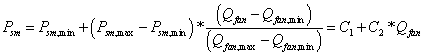
where ![]() and
and 
For Qfan < Qfan,min, Psm = Psm,min; for Qfan > Qfan,max, Psm = Psm,max
The minimum and maximum fan airflows (Qfan,min and Qfan,max) correspond respectively to the minimum and maximum duct static pressure set points (Psm,min and Psm,max).
If no duct static pressure reset scheme is used and the duct static pressure set point is constant, then parameter C2 is set to zero and C1 represents the constant duct static pressure set point.
The required alpha name of the exponential-modified skew normal performance curve (ref: Curve:ExponentialSkewNormal in Performance Curves) that parameterizes the normalized fan static efficiency (ηfan (xfan) / ηfan,max) at each time step for the normal operating (non-stall) region of the fan performance map as a function of xfan, which is defined as log-base-10 of Eu at the fan flow and pressure rise operating point divided by Eu at maximum fan static efficiency [log10(Eu / Eumax)]. In this region, xfan<=0.
The output of this curve is used to calculate the fan efficiency ηfan (xfan) at each time step by modifying ηfan,max (see Maximum Fan Static Efficiency field). This curve should have a maximum of 1.0 and should be valid for the range of volumetric flows and fan pressure rises anticipated for the simulation period.
The required alpha name of the exponential-modified skew normal performance curve (ref: Curve:ExponentialSkewNormal in Performance Curves) that parameterizes the normalized fan static efficiency (ηfan (xfan) / ηfan,max) at each time step for the stall region of the fan performance map as a function of xfan (see Normalized Fan Static Efficiency Curve Name– Non-Stall Region field). In this region, xfan>0.
The output of this curve is used to calculate the fan efficiency ηfan (xfan) at each time step by modifying ηfan,max (see Maximum Fan Static Efficiency field). This curve should have a maximum of 1.0 and should be valid for the range of volumetric flows and fan pressure rises anticipated for the simulation period.
The required alpha name of the sigmoid performance curve (ref: Curve:Sigmoid in Performance Curves) that parameterizes the normalized dimensionless airflow through the fan (φ (xspd) / φmax) at each time step for the normal operating (non-stall) region of the fan performance map as a function of xspd, which is defined as log-base-10 of Eu at the fan flow and pressure rise operating point divided by Eu at maximum fan static efficiency [log10(Eu / Eumax)]. In this region, xspd<=0.
The output of this curve is used to calculate the dimensionless airflow φ (xspd) at each time step by modifying φmax (see Maximum Dimensionless Fan Airflow field). This curve should have a maximum of 1.0 and should be valid for the range of volumetric flows and fan pressure rises anticipated for the simulation period.
The required alpha name of the sigmoid performance curve (ref: Curve:Sigmoid in Performance Curves) that parameterizes the normalized dimensionless airflow through the fan (φ (xspd) / φmax) at each time step for the stall region of the fan performance map as a function of xspd (see Normalized Dimensionless Airflow Curve Name – Non-Stall Region field). In this region, xspd>0.
The output of this curve is used to calculate the dimensionless airflow φ (xspd) at each time step by modifying φmax (see Maximum Dimensionless Fan Airflow field). This curve should have a maximum of 1.0 and should be valid for the range of volumetric flows and fan pressure rises anticipated for the simulation period.
The alpha name of the quartic polynomial performance curve (ref: Curve:Quartic in Performance Curves) that determines the maximum fan drive belt efficiency in logarithmic space (ηbelt,max,ln) as a function of xbelt,max. The curve is:
![]()
where xbelt,max = ln(Fbelt*Hfan,max) with Hfan,max expressed in terms of hp.
Note that ηbelt,max = exp(ηbelt,max,ln).
The output of this curve must be greater than zero and less than or equal to 1.0. If ηbelt,max is known, it is represented by coefficient C1 (=ln(ηbelt,max)). In this case, coefficients C2 through C5 are set to zero. If this field is left blank (e.g., there is no belt), the model assumes that the output of the modifier curve is 1.0 for the entire simulation (maximum belt efficiency = 1.0).
The alpha name of the single rectangular hyperbola type 2 performance curve (ref: Curve:RectangularHyperbola2 in Performance Curves) that determines the normalized (par-load) fan drive belt efficiency (ηbelt (xbelt) /ηbelt,max) as a function of xbelt. Normalized belt efficiency is represented by a segmented curve with three different regions. The curve for Region 1 (0 <= xbelt < xbelt,trans) is:
ηbelt (xbelt) / ηbelt,max = (C1·* xbelt) / (C2+xbelt) + C3·* xbelt
where xbelt = τbelt / τbelt,max; τbelt is the belt output torque that corresponds to the calculated power input to the fan shaft (Hfan, W) by the drive belt and the calculated fan shaft speed (ωfan, rpm).
The output of this curve is used to calculate the belt efficiency ηbelt (xbelt) in Region 1 at each time step by modifying ηbelt,max (see Maximum Belt Efficiency Curve Name field). The output of this curve must be greater than zero and less than or equal to 1.0 and should be valid for the range of volumetric flows and fan pressure rises anticipated for the simulation period.
If this field is left blank, the model assumes that the output of the modifier curve is 1.0 for the entire simulation (i.e., constant belt efficiency at ηbelt,max in Region 1).
The alpha name of the exponential decay performance curve (ref: Curve:ExponentialDecay in Performance Curves) that determines the normalized (part-load) fan drive belt efficiency (ηbelt (xbelt) /ηbelt,max) as a function of xbelt. Normalized belt efficiency is represented by a segmented curve with three different regions. The curve for Region 2 (xbelt,trans<= xbelt <= 1) is:
ηbelt (xbelt) /ηbelt,max = C1 + C2 * exp(C3*xbelt)
where xbelt = τbelt / τbelt,max; τbelt is the belt output torque that corresponds to the calculated power input to the fan shaft (Hfan, W) by the drive belt and the calculated fan shaft speed (ωfan, rpm).
The output of this curve is used to calculate the belt efficiency ηbelt (xbelt) in Region 2 at each time step by modifying ηbelt,max (see Maximum Belt Efficiency Curve Name field). The output of this curve must be greater than zero and less than or equal to 1.0 and should be valid for the range of volumetric flows and fan pressure rises anticipated for the simulation period.
If this field is left blank, the model assumes that the output of the modifier curve is 1.0 for the entire simulation (i.e., constant belt efficiency at ηbelt,max in Region 2).
The alpha name of the single rectangular hyperbola type 2 performance curve (ref: Curve:RectangularHyperbola2 in Performance Curves) that determines the normalized (part-load) fan drive belt efficiency (ηbelt (xbelt) /ηbelt,max) as a function of xbelt. Normalized belt efficiency is represented by a segmented curve with three different regions. The curve for Region 3 (xbelt> 1) is:
ηbelt (xbelt) /ηbelt,max = (C1·* xbelt) / (C2+xbelt) + C3·* xbelt
where xbelt = τbelt / τbelt,max; τbelt is the belt output torque that corresponds to the calculated power input to the fan shaft (Hfan, W) by the drive belt and the calculated fan shaft speed (ωfan, rpm).
The output of this curve is used to calculate the belt efficiency ηbelt (xbelt) in Region 3 at each time step by modifying ηbelt,max (see Maximum Belt Efficiency Curve Name field). The output of this curve must be greater than zero and less than or equal to 1.0 and should be valid for the range of volumetric flows and fan pressure rises anticipated for the simulation period.
If this field is left blank, the model assumes that the output of the modifier curve is 1.0 for the entire simulation (i.e., constant belt efficiency at ηbelt,max in Region 3).
The alpha name of the single rectangular hyperbola type 1 performance curve (ref: Curve: RectangularHyperbola1 in Performance Curves) that determines the maximum fan motor efficiency (ηmotor,max) as a function of xmotor,max. The curve is:
ηmotor,max = (C1 * xmotor,max) / (C2 + xmotor,max) + C3
where xmotor,max=ln(Fmotor * Hbelt,max) with Hbelt,max expressed in terms of hp. Hbelt,max is the maximum output power from the motor to the belt, which corresponds to the calculated maximum power input to the fan shaft (Hfan,max, W).
The output of this curve must be greater than zero and less than or equal to 1.0. If ηmotor,max is known, it is represented by coefficient C3. In this case, coefficients C1 and C2 are set to zero.
If this field is left blank, the model assumes that the output of the modifier curve is 1.0 for the entire simulation (maximum motor efficiency = 1.0).
The name of the HVAC system node to which the fan sends its outlet air.
The alpha name of the single rectangular hyperbola type 2 performance curve (ref: Curve:RectangularHyperbola2 in Performance Curves) that determines the normalized (part-load) fan motor efficiency (ηmotor (xmotor) /ηmotor,max) as a function of the motor load fraction xmotor. The curve is:
ηmotor (xmotor) /ηmotor,max = (C1 * xmotor) / (C2 + xmotor) + (C3·* xmotor)
where xmotor = Hbelt / Hbelt,max. Hbelt is the calculated output power from the motor to the belt (W), which corresponds to the calculated power input to the fan shaft (Hfan, W).
The output of this curve is used to calculate the motor efficiency (ηmotor (xmotor)) at each time step by modifying ηmotor,max (see Maximum Motor Efficiency Curve Name field). The output of this curve must be greater than zero and less than or equal to 1.0 and should be valid for the range of volumetric flows and fan pressure rises anticipated for the simulation period.
If this field is left blank, the model assumes that the output of the modifier curve is 1.0 for the entire simulation (i.e., constant motor efficiency at ηmotor,max).
The alpha name of the single rectangular hyperbola type 2 performance curve (e.g., Curve:RectangularHyperbola2 in Performance Curves) that determines the VFD efficiency (ηVFD (xVFD)) as a function of the fractional input power of the motor or fractional motor speed (xVFD). An example of the curve is:
ηVFD (xVFD) = (C1 * xVFD) / (C2+xVFD) + C3 * xVFD
where xVFD = Hmotor / Hmotor,max or ωmotor / ωmotor,max
The output of this curve is used to calculate the VFD efficiency ηVFD (xVFD) at each time step. The output of this curve must be greater than zero and less than or equal to 1.0 and should be valid for the range of volumetric flows and fan pressure rises anticipated for the simulation period.
If this field is left blank, the model assumes that the output of the modifier curve is 0.97 for the entire simulation (i.e., constant VFD efficiency of 0.97).
Allows you to specify a user-defined end-use subcategory, e.g., "Central System". A new meter for reporting is created for each unique subcategory (ref: Report Meter). Subcategories are also reported in the ABUPS table. If this field is omitted or blank, the fan will be assigned to the "General" end-use subcategory.
An example of use in an IDF:
Fan:ComponentModel,
Supply Fan 1, ! Fan Name
Main Heating Coil 1 Outlet Node, ! Inlet Node Name
VAV Sys 1 Outlet Node, ! Outlet Node Name
FanAvailSched, ! Fan Schedule
autosize, ! Maximum Flow Rate [m3/s]
autosize, ! Minimum Flow Rate [m3/s]
1.0, ! Fan Sizing Factor [-]
0.3048, ! Fan Wheel Diameter [m]
0.0873288576, ! Fan Outlet Area [m2]
0.514, ! Maximum Fan Static Efficiency [-]
9.76, ! Euler Number at Maximum Fan Static Efficiency [-]
0.160331811647483, ! Maximum Dimensionless Fan Airflow [-]
autosize, ! Motor/Fan Pulley Ratio [-]
autosize, ! Belt Maximum Torque [N m]
1.0, ! Belt Sizing Factor [-]
0.167, ! Belt Fractional Torque Transition [-]
1800, ! Motor Maximum Speed [rpm]
autosize, ! Maximum Motor Output Power [W]
1.0, ! Motor Sizing Factor [-]
1.0, ! Motor In Airstream Fraction [-]
Power, ! VFD Efficiency Type
autosize, ! Maximum VFD Output Power [W]
1.0, ! VFD Sizing Factor [-]
VSD Example, ! Fan Pressure Rise Curve Name
DiagnosticSPR, ! Duct Static Pressure Reset Curve Name
FanEff120CPLANormal, ! Fan Efficiency Curve Name – Non-Stall
FanEff120CPLAStall, ! Fan Efficiency Curve Name - Stall
FanDimFlowNormal, ! Dimensionless Airflow Curve Name-Non-Stall
FanDimFlowStall, ! Dimensionless Airflow Curve Name-Stall
BeltMaxEffMedium, ! Maximum Belt Efficiency Curve Name
BeltPartLoadRegion1, ! Normalized Belt Efficiency Curve Name
BeltPartLoadRegion2, ! Normalized Belt Efficiency Curve Name
BeltPartLoadRegion3, ! Normalized Belt Efficiency Curve Name
MotorMaxEffAvg, ! Maximum Motor Efficiency Curve Name
MotorPartLoad, ! Normalized Motor Efficiency Curve Name
VFDPartLoad; ! VFD Efficiency Curve Name
HVAC,Average,Fan Electric Power[W]
HVAC,Average,Fan Delta Temp[C]
HVAC,Sum,Fan Electric Consumption[J]
This output field contains the average electricity consumption rate for the fan in Watts for the timestep being reported.
This output field contains the average rise in air temperature across the fan (outlet air temperature minus inlet air temperature) in degrees Celsius for the timestep being reported.
This output field contains the electricity consumption of the fan in Joules for the timestep being reported. This output is also added to a report meter with Resource Type = Electricity, End Use Key= Fans, Group Key= System (ref. Report Meter).
Several parameters input by the user or calculated during component sizing for the design condition (maximum system airflow) are reported separately in the <filename>.eio file. These parameters include fan airflow and pressure rise; fan shaft input, motor output, VFD output, and VFD input (rated) power; pulley drive ratio; belt output torque; and fan, belt, motor, VFD, and combined system efficiencies. They can be identified by lines in the .eio file beginning with “Component Sizing Information, Fan:ComponentModel”. The same values are also reported under the ComponentSizingSummary heading in the <filename>Table.html file.
The electric steam humidifier is a component that represents an electrically heated, self contained steam humidifier. The component uses electrical energy to convert ordinary tap water to steam which it then injects into the supply air stream by means of a blower fan. The actual unit might be an electrode-type humidifier or a resistance-type humidifier.
The humidifier model includes local control of the humidifier unit to meet a humidity ratio setpoint on its air outlet node. A set point manager is needed to put a setpoint on the exit node but no other local controllers are needed. The humidifier will add moisture to meet the humidity ratio setpoint.
A unique user assigned name for a particular humidifier unit. Any reference to this unit by another object will use this name.
The name of the schedule (ref: Schedule) that denotes whether the unit can run during a given hour. A schedule value greater than 0 (usually 1 is used) indicates that the unit can be on during the hour. A value less than or equal to 0 (usually 0 is used) denotes that the unit must be off for the hour.
The nominal full output water addition rate of the unit in m3/sec of water at 5.05 C.
The nominal full output power consumption of the unit in watts, exclusive of the blower fan power consumption and any standby power.
The nominal full output power consumption of the blower fan in watts.
The standby power consumption in watts. This amount of power will be consumed whenever the unit is available (as defined by the availability schedule).
The name of the HVAC system node from which the unit draws inlet air.
The name of the HVAC system node to which the unit sends its outlet air.
This field is optional. If left blank or omitted, then the humidifier obtains its water directly from the mains water. If the name of a Water Storage Tank is specified, then the humidifier will try to obtain its water from that tank. If the tank can’t provide all the water then the rest will be drawn from the mains and the humidifier will still operate.
An IDF example:
Humidifier:Steam:Electric,
Humidifier 1, !- Name
FanAndCoilAvailSched, !- Availability Schedule Name
0.00000379, !- Rated Capacity {m3/s}
10200., !- Rated Power {W}
27., !- Rated Fan Power {W}
2., !- Standby Power {W}
Cooling Coil Air Outlet Node, !- Air Inlet Node Name
Air Loop Outlet Node; !- Air Outlet Node Name
HVAC,Average,Humidifier Water Consumption Rate[m3/s]
HVAC,Sum,Humidifier Water Consumption[m3]
HVAC,Average,Humidifier Electric Power[W]
HVAC,Sum,Humidifier Electric Consumption[J]
Zone,Meter,Humidifier:Water [m3]
Zone,Meter,Humidifier:Electricity [J]
HVAC,Average,Humidifier Water From Storage Tank Rate [m3/s]
HVAC,Sum,Humidifier Water From Storage Tank [m3]
HVAC,Average,Humidifier Water Starved By Storage Tank Rate [m3/s]
HVAC,Sum,Humidifier Water Starved By Storage Tank [m3]
Zone,Meter,Humidifier:MainsWater [m3]
HVAC,Sum,Humidifier Water Mains Draw [m3]
This field reports the water consumption rate of the steam humidifier in cubic meters of water per second.
This ouput is the cubic meters of water consumed by the steam humidifier over the timestep being reported.
This output is the electricity consumption rate in Watts of the steam humidifier.
This is the electricity consumption in Joules of the steam humidifier over the timestep being reported.
This meter output contains the sum of the water consumed (in cubic neters of water during the report timestep) by all the steam humidifiers at the HVAC level in the simulation.
This meter output contains the sum of the electricity consumed (in Joules during the report timestep) by all the steam humidifiers at the HVAC level in the simulation.
These outputs contain the rate and volume of water obtained from water storage tank. These are only present if the humidifier is connected to a Water Storage Tank for its water supply.
These outputs contain the rate and volume of water that could not be obtained from the water storage tank. The component will still operate as if it did get all the water with the balance obtained directly from the mains
This output contains the volume of water obtained from the mains.
This object models a solid desiccant dehumidifier (excluding associated fans). The process air stream is the air which is dehumidified. The regen air stream is the air which is heated to regenerate the desiccant. This object determines the process air outlet conditions, the load on the regeneration heating coil, the electric power consumption for the wheel rotor motor, and the regeneration air fan mass flow rate. All other heat exchangers are modeled as separate objects connected to the inlet and outlet nodes of the dehumidifier. The solid desiccant dehumidifier is typically used in an AirLoopHVAC:OutdoorAirSystem object, but can also be specified in any AirLoopHVAC.
This alpha field contains the identifying name for the desiccant dehumidifier.
The name of the schedule (ref: Schedule) that denotes whether the desiccant unit can run during a given hour. A schedule value greater than 0 (usually 1 is used) indicates that the unit can be on during the hour. A value less than or equal to 0 (usually 0 is used) denotes that the unit must be off for the hour.
The name of the node entering the process side of the desiccant wheel.
The name of the node leaving the process side of the desiccant wheel.
The name of the node entering the regeneration side of the desiccant wheel after the regeneration coil.
Node name for air entering the regeneration fan, mass flow is set by this desiccant dehumidifier model.
Type of setpoint control. Options are
n LeavingMaximumHumidityRatioSetpoint
n SystemNodeMaximumHumidityRatioSetpoint
LeavingMaximumHumidityRatioSetpoint means that the unit is controlled to deliver air at the Leaving Maximum Humidity Ratio Setpoint, using bypass dampers to prevent overdrying.
SystemNodeMaximumHumidityRatioSetpoint means that the unit is controlled to deliver air at the maximum humidity ratio setpoint (System Node Humidity Ratio Max) on the Process Air outlet node, using bypass dampers to prevent overdrying. This setpoint must be established using a set point manager which sets the MaximumHumidityRatio control variable:
n SetpointManager:SingleZone:Humidity:Maximum
n SetpointManager:MultiZone:MaximumHumidity:Average
n SetpointManager:MultiZone:Humidity:Maximum
This will also require the use of a ZoneControl:Humidistat object. If the dehumidifer is located in the outdoor air stream, it may also be necessary to use SetpointManager:OutdoorAirPretreat.
Fixed setpoint for maximum process air leaving humidity ratio. Applicable only when Control Type = LeavingMaximumHumidityRatioSetpoint.
Process air flow rate in m3/s at nominal conditions.
Process air velocity in m/s at nominal flow.
Power input to wheel rotor motor in W.
Type of heating coil object for regeneration air. Must be one of Coil:Heating:Electric or Coil:Heating:Gas.
Name of heating coil object for regeneration air.
Type of fan object for regeneration air. For UserCurves performance (see below) Fan:VariableVolume and Fan:ConstantVolume are valid. For Default performance (see below) only Fan:VariableVolume is valid.
Name of fan object for regeneration air.
Specifies whether the Default performance model or UserCurves curves should be used to model the performance. The default model is a generic solid desiccant wheel using performance curves of the form:
curve = C1 + C2*edb + C3*edb**2 + C4*ew + C5*ew**2 +
C6*vel + C7*vel**2 + C8*edb*ew + C9*edb**2*ew**2 +
C10*edb*vel + C11*edb**2*vel**2 + C12*ew*vel + C13*ew**2*vel**2 +
C14*ALOG(edb) + C15*ALOG(ew) + C16*ALOG(vel)
edb = process entering drybulb temperature [C]
ew = process entering humidity ratio [kg/kg]
vel = process air velocity [m/s]
The Default curves are valid for the following range of process inlet conditions: dry-bulb temperatures of 1.67C (35F) to 48.9C (120F) and humidity ratios of 0.002857 kg/kg (20 gr/lb) to 0.02857 kg/kg (200 gr/lb). If the process inlet conditions are outside this range, the dehumidifier will not operate.
If UserCurves are specified, then performance is calculated as follows:
Leaving Dry-bulb = (Leaving Dry-Bulb Function of Entering Dry-Bulb and Humidity Ratio Curve) * (Leaving Dry-Bulb Function of Air Velocity Curve)
Leaving Humidity Ratio = (Leaving Humidity Ratio Function of Entering Dry-Bulb and Humidity Ratio Curve) * (Leaving Humidity Ratio Function of Air Velocity Curve)
Regeneration Energy = (Regeneration Energy Function of Entering Dry-Bulb and Humidity Ratio Curve) * (Regeneration Energy Function of Air Velocity Curve)
Regeneration Velocity = (Regeneration Velocity Function of Entering Dry-Bulb and Humidity Ratio Curve) * (Regeneration Velocity Function of Air Velocity Curve)
The UserCurves are limited to the following range of process inlet conditions (essentially not limited): dry-bulb temperatures of –73.3C (-100F) to 65.6C (150F) and humidity ratios of 0.0 kg/kg (0 gr/lb) to 0.21273 kg/kg (1490 gr/lb). If the process inlet conditions are outside this range, the dehumidifier will not operate.
When the Default performance model is selected, the remaining fields are ignored.
This field is applicable only when UserCurves performance model type is specified.
Leaving dry-bulb of process air as a function of entering dry-bulb and entering humidity ratio, biquadratic curve.
curve = C1 + C2*edb + C3*edb**2 + C4*ew + C5*ew**2 + C6*edb*ew
edb = process entering drybulb temperature [C]
ew = process entering humidity ratio [kg/kg]
This field is applicable only when UserCurves performance model type is specified.
Leaving dry-bulb of process air as a function of air velocity, quadratic curve.
curve = C1 + C2*v + C3*v**2
v = process air velocity [m/s]
This field is applicable only when UserCurves performance model type is specified.
Leaving humidity ratio of process air as a function of entering dry-bulb and entering humidity ratio, biquadratic curve
curve = C1 + C2*edb + C3*edb**2 + C4*ew + C5*ew**2 + C6*edb*ew
edb = process entering drybulb temperature [C]
ew = process entering humidity ratio [kg/kg]
This field is applicable only when UserCurves performance model type is specified.
Leaving humidity ratio of process air as a function of process air velocity, quadratic curve.
curve = C1 + C2*v + C3*v**2
v = process air velocity [m/s]
This field is applicable only when UserCurves performance model type is specified.
Regeneration energy [J/kg of water removed] as a function of entering dry-bulb and entering humidity ratio, biquadratic curve
curve = C1 + C2*edb + C3*edb**2 + C4*ew + C5*ew**2 + C6*edb*ew
edb = process entering drybulb temperature [C]
ew = process entering humidity ratio [kg/kg]
This field is applicable only when UserCurves performance model type is specified.
Regeneration energy [J/kg of water removed] as a function of process air velocity, quadratic curve.
curve = C1 + C2*v + C3*v**2
v = process air velocity [m/s]
This field is applicable only when UserCurves performance model type is specified.
Regeneration velocity [m/s] as a function of entering dry-bulb and entering humidity ratio, biquadratic curve
curve = C1 + C2*edb + C3*edb**2 + C4*ew + C5*ew**2 + C6*edb*ew
edb = process entering drybulb temperature [C]
ew = process entering humidity ratio [kg/kg]
This field is applicable only when UserCurves performance model type is specified.
Regeneration velocity [m/s] as a function of process air velocity, quadratic curve.
curve = C1 + C2*v + C3*v**2
v = process air velocity [m/s]
This field is applicable only when UserCurves performance model type is specified.
Nominal regeneration temperature upon which the regeneration energy modifier curve is based. This input is ignored when Performance Model Type = Default, which assume a regeneration temperature of 121C.
An example of this statement in an IDF is:
Dehumidifier:Desiccant:NoFans,
Desiccant 1, !- Name
FanAndCoilAvailSched, !- Availability Schedule Name
Outside Air Inlet Node, !- Process Air Inlet Node Name
Desiccant Process Outlet Node, !- Process Air Outlet Node Name
Regen Coil Out Node, !- Regeneration Air Inlet Node Name
Outside Air Inlet Node 2,!- Regeneration Fan Inlet Node Name
SystemNodeMaximumHumidityRatioSetpoint, !- Control Type
0.007, !- Leaving Maximum Humidity Ratio Setpoint {kg-H2O/kg-air}
1, !- Nominal Process Air Flow Rate {m3/s}
2.5, !- Nominal Process Air Velocity {m/s}
10, !- Rotor Power {W}
Coil:Heating:Gas, !- Regeneration Coil Object Type
Desiccant Regen Coil, !- Regeneration Coil Name
Fan:VariableVolume, !- Regeneration Fan Object Type
Desiccant Regen Fan, !- Regeneration Fan Name
UserCurves, !- Performance Model Type
Desiccant DryBulb fTW Curve, !- Leaving Dry-Bulb Function of Entering Dry-Bulb and Humidity Ratio Curve Name
Desiccant DryBulb fV Curve, !- Leaving Dry-Bulb Function of Air Velocity Curve Name
Desiccant HumRat fTW Curve, !- Leaving Humidity Ratio Function of Entering Dry-Bulb and Humidity Ratio Curve Name
Desiccant HumRat fV Curve, !- Leaving Humidity Ratio Function of Air Velocity Curve Name
Desiccant RegenEnergy fTW Curve, !- Regeneration Energy Function of Entering Dry-Bulb and Humidity Ratio Curve Name
Desiccant RegenEnergy fV Curve, !- Regeneration Energy Function of Air Velocity Curve Name
Desiccant RegenVel fTW Curve, !- Regeneration Velocity Function of Entering Dry-Bulb and Humidity Ratio Curve Name
Desiccant RegenVel fV Curve, !- Regeneration Velocity Function of Air Velocity Curve Name
121; !- Nominal Regeneration Temperature {C}
HVAC,Sum,Desiccant Dehumidifier Water Removed [kg]
HVAC,Average,Desiccant Dehumidifier Water Removal Rate[kg/s]
HVAC,Average,Desiccant Dehumidifier Part Load Ratio[]
HVAC,Average,Desiccant Dehumidifier Electric Power [W]
HVAC,Sum,Desiccant Dehumidifier Electric Consumption [J]
HVAC,Average,Desiccant Dehumidifier Specific Regen Energy [J/kg H2O]
HVAC,Average,Desiccant Dehumidifier Regen Energy Rate[W]
HVAC,Sum,Desiccant Dehumidifier Regen Energy[J]
HVAC,Average,Desiccant Dehumidifier Regen Air Velocity[m/s]
HVAC,Average,Desiccant Dehumidifier Regen Air Mass Flow Rate[kg/s]
HVAC,Average,Desiccant Dehumidifier Process Air Mass Flow Rate[kg/s]
Mass of water removed from process air stream.
Rate of water removal from process air stream.
Dehumidifier water removal rate divided by full-load water removal rate.
Dehumidifier rotor electric power.
Dehumidifier rotor electric energy.
Regeneration heating coil energy divided by water removed.
Regeneration heating coil output rate.
Regeneration heating coil output energy.
Regeneration air velocity.
Regeneration air mass flow rate.
Process air mass flow rate.
The Dehumidifier:Desiccant:System object models the dehumidification of an air stream, normally called the process air stream. A second heated air stream, called the regeneration air stream, is used to remove the collected moisture from the desiccant heat exchanger and this moisture-laden air is then usually exhausted from the building. This Dehumidifier:Desiccant:System object is similar to the Dehumidifier:Desiccant:NoFans object but has some additional modeling capabilities.
The Dehumidifier:Desiccant:System object in EnergyPlus is a compound object that can be placed anywhere in an air loop (AirLoopHVAC). Common locations for this object are in an AirLoopHVAC:OutdoorAirSystem or in the main air loop (AirLoopHVAC) downstream of a cooling coil (postcooling desiccant dehumidifier). This compound object coordinates the operation of several ‘children’ objects: a desiccant heat exchanger, a regeneration air fan, and an optional regeneration air heater. If this dehumidifier is placed in the main air loop immediately downstream of a direct expansion (DX) cooling coil, then the dehumidifier’s operation can be coordinated with the operation of the companion DX coil and it is also possible to specify that the DX system’s condenser waste heat can be used to help regenerate the desiccant heat exchanger. For the case of condenser waste heat regeneration, an optional exhaust fan can also be modeled by this desiccant dehumidifier compound object to help maintain a set point temperature for air entering the regeneration side of the desiccant heat exchanger.
It is important to note that the optional exhaust air fan is modeled internal to the Dehumidifier:Desiccant:System and a separate fan object should not be added to the input data file (idf) for this fan. On the other hand, a separate fan object is required in the input data file for the regeneration air fan.
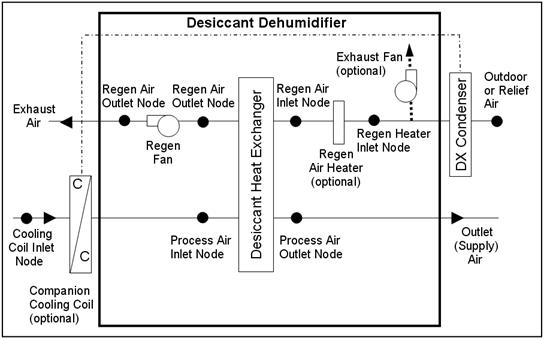
Figure 124. Schematic of Dehumidifier:Desiccant:System with Draw Through Regeneration Fan Placement
A schematic of the compound object Dehumidifier:Desiccant:System is shown in Figure 124 with the draw through regeneration air fan placement. Figure 125 shows the Dehumidifier:Desiccant:System object configured with the blow through regeneration air fan placement.
NOTE: As with any air loop compound object, the Dehumidifier:Desiccant:System object itself is specified on the AirLoopHVAC Branch or in the AirLoopHVAC:OutdoorAirSystem:EquipmentList for an AirLoopHVAC:OutdoorAirSystem. The children objects (e.g., desiccant heat exchanger, regeneration air fan, and optional regeneration air heater) must be specified separately in the input data file and their inlet/outlet connections must be as shown in Figure 124 or Figure 125.
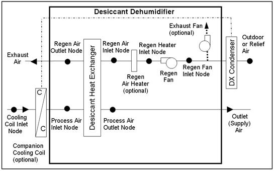
Figure 125. Schematic of Dehumidifier:Desiccant:System with Blow Through Regeneration Fan Placement
Currently the only heat exchanger choice for this object is HeatExchanger:Desiccant: BalancedFlow. So to model a Dehumidifier:Desiccant:System located in an air loop, the input data file should include the following objects:
· Dehumidifier:Desiccant:System (in an air loop (AirLoopHVAC) Branch or AirLoopHVAC:OutdoorAirSystem:EquipmentList for an AirLoopHVAC:OutdoorAirSystem)
· HeatExchanger:Desiccant:BalancedFlow (desiccant heat exchanger child object)
· HeatExchanger:Desiccant:BalancedFlow:PerformanceDataType1 (desiccant heat exchanger data object)
· ZoneControl:Humidistat, and one of:
n SetpointManager:SingleZone:Humidity:Maximum
n SetpointManager:MultiZone:Humidity:Maximum
n SetpointManager:MultiZone:MaximumHumidity:Average
· (when in an air loop (AirLoopHVAC) Branch), and SetpointManager:OutdoorAirPretreat (when in an AirLoopHVAC:OutdoorAirSystem) to place a maximum humidity ratio set point on the sensor node, typically the process air outlet node
· Fan:OnOff or Fan:ConstantVolume (regeneration air fan)
· Coil:Heating:Electric or Coil:Heating:Gas (optional regeneration air heater)
· Coil:Cooling:DX:SingleSpeed or Coil:Cooling:DX:TwoStageWithHumidityControlMode (optional companion cooling coil)
If the user wants to model the Dehumidifier:Desiccant:System in an AirLoopHVAC:OutdoorAirSystem, then the process air path of the dehumidifier should be located in the outdoor air stream and the regeneration air path may be placed in the relief air stream or modeled by the desiccant dehumidifier itself where the first node for the regeneration inlet air stream must be an outdoor air node. If the user wants to model the Dehumidifier:Desiccant:System in an air loop (AirLoopHVAC) Branch, then the process air path of the dehumidifier should be located in the air loop Branch object. For this case, the regeneration air stream is modeled by the desiccant dehumidifier object itself (i.e., not part of an air loop Branch statement) and the first node for the regeneration inlet air stream must be an outdoor air node (ref. Figure 124 or Figure 125).
A description of each input field for this object is provided below:
A unique, user-assigned name for a particular Dehumidifier:Desiccant:System. Any reference to this dehumidifier by another object will use this name.
The name of the schedule (ref: Schedule) that denotes whether the dehumidifier can operate during a given time period. A schedule value greater than 0 (usually 1 is used) indicates that the dehumidifier can operate. A value less than or equal to 0 (usually 0 is used) denotes that the dehumidifier will not operate (i.e., no heat exchange will take place and the regeneration air fan does not operate). For the case where companion cooling coil regeneration air heating has been specified, the desiccant dehumidifier’s exhaust fan serves as the condenser air fan for the cooling coil system so this availability schedule will not disable exhaust fan operation.
This alpha field contains the type of desiccant heat exchanger used with this dehumidifier. Currently, the only valid choice is HeatExchanger:Desiccant:BalancedFlow.
This alpha field contains the name of the desiccant heat exchanger used with this dehumidifier.
This alpha field specifies the name of the air loop node used to control desiccant heat exchanger operation. A set point manager must be used to place a maximum humidity ratio set point on this node (e.g., SetpointManager:SingleZone:Humidity:Maximum or SetpointManager:OutdoorAirPretreat).
This alpha field contains the type of regeneration air fan used. Available fan types are Fan:OnOff and Fan:ConstantVolume.
This alpha field contains the name of the regeneration air fan used with this dehumidifier.
This alpha field specifies the fan configuration used in the desiccant dehumidifier. Valid choices are ‘BlowThrough’ and ‘DrawThrough’, with a default of ‘DrawThrough’ if this field is left blank.
This alpha field contains the type of heating coil used to heat the regeneration air stream. Valid choices are Coil:Heating:Electric and Coil:Heating:Gas. This field may be left blank when no regeneration air heater is required.
This alpha field contains the name of the heating coil used to heat the regeneration air stream. This field may be left blank when no regeneration air heater is required.
This optional numeric field specifies the regeneration air inlet temperature setpoint in Celsius. The regeneration air heater and/or the companion coil regeneration air heating will be controlled to this temperature to the extent possible. This field may be left blank when no regeneration air heater is required or when control of the exhaust fan used with the companion coil regeneration air heating option is not required.
This optional alpha field contains the type of companion cooling coil used with this desiccant dehumidifier. The only valid choices are Coil:Cooling:DX:SingleSpeed and Coil:Cooling:DX:TwoStageWithHumidityControlMode.
This optional alpha field contains the name of the companion cooling coil used with this desiccant dehumidifier. This field may be left blank when no companion cooling coil is being modeled.
This choice field specifies if the companion cooling coil is located immediately upstream of the dehumidifier’s process inlet. Valid choices are Yes and No. If Yes is selected, then the outlet air node for the companion cooling coil must be the same as the dehumidifier’s process air inlet node (i.e., the process air inlet node name for the desiccant heat exchanger specified for this desiccant dehumidifier). For this case, the companion cooling coil and the desiccant dehumidifier are assumed to operate “in tandem”; that is, if the simulation determines that the companion cooling coil is unable to meet the humidity set point specified on the sensor node based on its own operation, then the desiccant dehumidifier operates at the same time and for the same duration as the cooling coil to provide improved dehumidification. If No is selected, then the dehumidifier will control to the humidity set point specified on the sensor node to the extent possible. The default value is No if this field is left blank.
This choice field determines if the companion cooling coil’s condenser waste heat is used to heat the regeneration inlet air. Valid choices are Yes and No. The default value is No if this field is left blank.
This optional numeric field contains the maximum fan volumetric flow rate for the exhaust fan in cubic meters per second. As noted previously, this exhaust fan is modeled internally by the Dehumidifier:Desiccant:System object and a separate fan object should NOT be specified in the input data file for this fan. This field is used only when a companion cooling coil is specified and the ‘Companion Coil Regeneration Air Heating’ field is set to ‘Yes’. This field must be used in conjunction with the ‘Exhaust Fan Maximum Power’ and the ‘Exhaust Fan Power Curve Name’ input fields. The model assumes that the exhaust fan will operate as needed to maintain the ‘Regeneration Inlet Air Setpoint Temperature’, up to the maximum flow rate specified in this input field. If the desiccant dehumidifier is OFF for a simulation timestep but its companion cooling coil is operating and is specified to provide regeneration air heating, then the exhaust fan operates at this maximum air flow rate (i.e., this fan serves as the condenser fan for the companion cooling coil system when regeneration air heating is specified, so the inputs to the companion cooling coil object should not include the condenser fan energy since the condenser fan energy is modeled by the Dehumidifier:Desiccant:System object).
This optional numeric field contains the maximum power for the exhaust fan in Watts (i.e., at the Exhaust Fan Maximum Flow Rate). This field is used only when a companion cooling coil is used and the ‘Companion Coil Regeneration Air Heating’ field is set to ‘Yes’. This field must be used in conjunction with the ‘Exhaust Fan Maximum Flow Rate’ and the ‘Exhaust Fan Power Curve Name’ input fields.
This optional alpha field contains the name of the exhaust fan power modifier curve. This field is used only when a companion cooling coil is used and the ‘Companion Coil Regeneration Air Heating’ field is set to ‘Yes’. This field must be used in conjunction with the ‘Exhaust Fan Maximum Flow Rate’ and the ‘Exhaust Fan Maximum Power’ input fields. If this field is blank, the exhaust fan operates (when required) at the maximum power specified in the field above. The curve object type for this Exhaust Fan Power Curve Name must be Curve:Cubic or Curve:Quadratic. The curve object (Curve:Cubic or Curve:Quadratic) defines the change in exhaust fan power as a function of the ratio of the actual exhaust air flow rate divided by the maximum flow rate.
Following is an example input for this object:
Dehumidifier:Desiccant:System,
Desiccant 1, !- Name
FanAvailSched, !- Availability Schedule Name
HeatExchanger:Desiccant:BalancedFlow, !- Desiccant Heat Exchanger Object Type
Desiccant Heat Exchanger 1, !- Desiccant Heat Exchanger Name
HX Process Outlet Node, !- Sensor Node Name
Fan:ConstantVolume, !- Regeneration Air Fan Object Type
Desiccant Regen Fan, !- Regeneration Air Fan Name
DrawThrough, !- Regeneration Air Fan Placement
Coil:Heating:Gas, !- Regeneration Air Heater Object Type
Desiccant Regen Coil, !- Regeneration Air Heater Name
46.111111, !- Regeneration Inlet Air Setpoint Temperature {C}
Coil:Cooling:DX:SingleSpeed, !- Companion Cooling Coil Object Type
Desiccant DXSystem Cooling Coil, !- Companion Cooling Coil Name
Yes, !- Companion Cooling Coil Upstream of Dehumidifier Process Inlet
Yes, !- Companion Coil Regeneration Air Heating
1.05, !- Exhaust Fan Maximum Flow Rate {m3/s}
50, !- Exhaust Fan Maximum Power {W}
EXHAUSTFANPLF; !- Exhaust Fan Power Curve Name
HVAC,Sum,Desiccant Dehumidifier Water Removed [kg]
HVAC,Average,Desiccant Dehumidifier Water Removal Rate [kg/s]
HVAC,Average,Desiccant Dehumidifier Part Load Ratio []
HVAC,Average,Desiccant Dehumidifier Exhaust Fan Electric Power [W]
HVAC,Sum,Desiccant Dehumidifier Exhaust Fan Electric Consumption [J]
This output is the mass of water removed from the process air stream in kilograms for the timestep being reported.
This output is the average rate of water removal from the process air stream in kilograms per second for the timestep being reported.
This output is the fraction of time that the desiccant heat exchanger (and associated regeneration air heater and fans, if appropriate) operate for the timestep being reported.
This output is the average electric consumption rate for the exhaust fan in Watts for the timestep being reported.
This output is the electric consumption for the exhaust fan in Joules for the timestep being reported. This output is also added to a report meter with Resource Type = Electricity, EndUseKey = Cooling, GroupKey = System (ref. Report Meter).
The Energy Management System (EMS) is one of the high-level control methods available in EnergyPlus. An EMS is able to access a wide variety of “sensor” data and use this data to direct various types of control actions. The concept is to emulate, inside EnergyPlus, the types of controls possible with the digital energy management systems used in real buildings.
In the hierarchy of EnergyPlus controls, the EMS module is a high-level, generalized, supervisory control for building systems. The EMS replicates the functionality of many of the existing high-level control objects in EnergyPlus. Similar to the AvailabilityManager objects, the EMS can turn on and off pumps and fans. Similar to the DemandManager objects, the EMS can turn on and off lights and electric equipment, change the set points on zone thermostats, and dispatch on-site generation. Similar to the SetpointManager objects, the EMS can change the set points on system nodes. Similar to the PlantEquipmentOperation objects, the EMS can turn on and off supply-side heating, cooling, and heat rejection equipment, i.e., boilers, chillers, cooling towers, etc. Similar to the ElectricLoadCenter:Distribution, the EMS can turn on and off on-site generation equipment.
A separate document called Application Guide for EMS contains much more information on how to use the EMS. The EMS uses the EnergyPlus Runtime Language (Erl) for custom programming of control routines.
The EnergyManagmentSystem:Sensor object is used to declare an Erl variable that is linked to EnergyPlus report variables or meters. EMS sensors are used to get information from elsewhere in the model for use in control calculations. The separate output files called eplusout.rdd and eplusout.mdd provide a listing of the output variables and meters that can be used as sensors.
This field contains a unique name for the sensor that becomes the name of a variable for use in Erl programs. No spaces are allowed in the object name. This name will be a global variable in Erl programs and cannot duplicate any other global scope Erl variable.
The key reference for the specified report variable. For example, if System Node Temp is the report variable, the unique node name is the key. The Key Name field should be omitted for weather variables and meters because they do not have a key.
The name of the report variable or meter that is to be mapped to the Erl variable for the sensor. The names that can be used in a specific model are included in the .RDD output file.
Examples of this object follow.
EnergyManagementSystem:Sensor,
T1, !Name
Perimeter_ZN_1 , ! Output:Variable or Output:Meter Index Key Name
Zone Mean Air Temperature ; ! Output:Variable or Output:Meter Name
EnergyManagementSystem:Sensor,
PMV5, !Name
Core_ZN , ! Output:Variable or Output:Meter Index Key Name
FangerPMV ; ! Output:Variable or Output:Meter Name
EnergyManagementSystem:Sensor,
T_VAV5FanIn, !Name
VAV_5_HeatC-VAV_5_FanNode , ! Output:Variable Index Key Name
System Node Temp ; ! Output:Variable or Output:Meter Name
EnergyManagementSystem:Sensor,
cooling_setpoint, ! Name
CLGSETP_SCH , ! Output:Variable or Output:Meter Index Key Name
Schedule Value ; ! Output:Variable or Output:Meter Name
This object maps an Erl variable to a control actuator elsewhere in EnergyPlus. The EMS then initiates control actions by changing the value of this variable inside an Erl program. The Application Guide for EMS contains much more information on EMS actuators. The eplusout.EDD file can contain a listing of the actuators available for a specific model.
The field contains a unique name for the actuator that becomes the name of a variable for use in Erl programs. No spaces are allowed in the object name. This name will be a global variable in Erl programs and cannot duplicate any other global scope Erl variable.
This field defines a unique name for the specific entity that is to be controlled. The names for each individual component are listed in the EDD output file when Verbose mode is used – see the input object Output:EnergyManagementSystem for more on the EDD file. These will often be user-defined names of input objects or system nodes, but some actuators are automatically setup by the program and will not be completely user-defined.
The field defines the type of the entity that is to be controlled by the actuator. The component types available vary with the specifics of individual models. The types of components that can be used as actuators in a specific model are listed in the EDD output file – see the input object Output:EnergyManagementSystem for more on the EDD file. Components can be object types defined elsewhere in the IDD but there are other types of entities such as nodes and system-level actuators that do not directly correspond to IDF objects.
This field defines the type of control to be done on the specific entity being controlled. The control types available are listed in the EDD output. Specific components may have more than one type of control available, such as flow rate or temperature, and this field is used to distinguish between them.
Example input objects.
EnergyManagementSystem:Actuator,
VAV_5_NightCycleStatus, ! Name
VAV_5, ! Actuated Component Unique Name
AirLoopHVAC, ! Actuated Component Type
Availability Status; ! Actuated Component Control Type
EnergyManagementSystem:Actuator,
VAV_1_SAT_setpoint, ! Name
VAV_1 Supply Equipment Outlet Node , ! Actuated Component Unique Name
System Node Setpoint, ! Actuated Component Type
Temperature Setpoint; ! Actuated Component Control Type
EnergyManagementSystem:Actuator,
myCLGSETP_SCH_Override, ! Name
CLGSETP_SCH, !- Actuated Component Unique Name
Schedule:Constant, ! Actuated Component Type
Schedule Value; ! Actuated Component Control Type
The EnergyManagementSystem:ProgramCallingManager object is used to specify when individual Erl programs are run. This object manages two temporal aspects of running Erl programs. The first is when they are run relative to the rest of EnergyPlus, and the second is when they are run relative to each other. EMS applications can use multiple EnergyManagementSystem:ProgramCallingManager objects. For example, one manager may execute an initialization program once at the beginning of the run period while additional managers call various sets of programs from different EMS Calling Points.
Control schemes can be organized using a multiple Erl programs and this object this specifies the order in which they are executed. Program Name 1 is run first, Program Name 2 is run second, etc. The run order can be important if there are interactions or dependencies between two or more programs. Within each program there may be calls to execute subroutine programs but only calling managers are used to execute main-level programs.
This is a unique name for this particular program manager.
This field describes when the Erl programs managed under this object are called during an EnergyPlus simulation. All of the programs listed are called at this same calling point. There are 13 possible calling points summarized below. For more information see the section on EMS Calling Points in the Application Guide for EMS.
· BeginNewEnvironment. This calling point occurs near the beginning of each environment period. Environment periods include sizing periods such as design days and run periods. This calling point will not be useful for control actions but is useful for initialization of Erl program variables and other one-time set up actions for EMS.
· AfterNewEnvironmentWarmUpIsComplete. This calling point occurs at the beginning of each environment period but after warm up days are complete. Warm up days are used to condition the transient aspects of the model with the first day before proceeding. This calling point will not be useful for control actions but is useful for re-initializing Erl programs with fresh values after warm up is complete. Programs called from this point might be used to reset counters or summed variables that would change during warmup.
· BeginTimestepBeforePredictor. This calling point happens near the beginning of each timestep but before predictor executes. “Predictor” refers to the step in EnergyPlus modeling where the zone’s thermal loads are calculated. This calling point is useful for controlling components that affect the thermal loads that the systems will be attempting to meet. Programs called from this point might actuate the building envelope or internal gains based on current weather and the results from the previous timestep.
· AfterPredictorBeforeHVACManagers. This calling point happens each timestep just after predictor executes but before the traditional supervisory control models for SetpointManager and AvailabilityManager are called. This calling point is useful for a variety of control actions. However, if there are conflicts, the EMS control actions may be overwritten by the actions of any traditional SetpointManagers or AvailabilityManagers in the model.
· AfterPredictorAfterHVACManagers. This calling point happens each timestep after predictor executes and after the SetpointManager and AvailabilityManager models are called. This calling point is useful for a variety of control actions. However, if there are conflicts, SetpointManager or AvailabilityManager actions may be overwritten by EMS control actions.
· InsideHVACSystemIterationLoop. This calling point happens each HVAC iteration. The HVAC systems solvers iterate to convergence within each timestep and this calling point is inside this iteration loop. This calling point is useful for a variety of control actions. Being inside the interation loop, this calling point has the advantage that input data need not necessarily be lagged from prior timestep results and can, in some cases, improve the accuracy of controls. The disadvantage is that programs may run an excessive number of times slowing down the execution of the program.
· EndOfZoneTimestepBeforeZoneReporting. This calling point happens each zone timestep just before the output reports are updated for zone-timestep variables and meters. This calling point is useful for custom report variables with “Zone” frequency because they will be in sync with the rest of the zone report variables.
· EndOfZoneTimestepAfterZoneReporting. This calling point happens each zone timestep just after the output reports are updated for zone-timestep variables and meters. This calling point is the last one of a timestep and is useful for making control decisions for the next zone timestep using the final meter values for the current zone timestep.
· EndOfSystemTimestepBeforeHVACReporting. This calling point happens each system timestep just before the output reports are updated for HVAC-timestep variables and meters. This calling point is useful for custom report variables with “HVAC” frequency because they will be in sync with the rest of the system report variables.
· EndOfSystemTimestepAfterHVACReporting. This calling point happens each system timestep just after the output reports are updated for HVAC-timestep variables and meters. This calling point is useful for making control decisions for the next system timestep using the final meter values for the current system timestep.
· EndOfZoneSizing. This calling point happens once during each simulation and only if the run is set to do zone sizing. The calling point occurs just after the native zone sizing calculations are completed but before the sizing results are finalized. This calling point is useful for taking the intermediate results of zone sizing calculations and modifying them based on custom calculations.
· EndOfSystemSizing. This calling pont happens once during each simulation and only if the run is set to do system sizing. The calling point occurs just after the native air system sizing calculations are completed but before the sizing results are finalized. This calling point is useful for taking the intermediate results of zone and system sizing calculations and modifying them based on custom calculations.
· AfterComponentInputReadIn. This calling point occurs early in the simulation when HVAC component’s input data has been processed but before any component-level calculations for automatic sizing. This calling point occurs once for each of the types of HVAC components that have EMS actuators for autosize overrides. This calling point is not directly useful for control actions but is useful for overriding the results of sizing at the component level.
The name of the EnergyManagementSystem:Program object that will be the first to run for the calling point.
The name of the EnergyManagementSystem:Program object that will be the second to run every system time step. Additional programs can be listed. The object is automatically extensible to accommodate as many programs as needed.
IDF examples:
EnergyManagementSystem:ProgramCallingManager,
Initialize EMS for Run , ! Name
BeginNewEnvironment , ! EnergyPlus Model Calling Point
InitializeMyEMS; ! Program Name 1
EnergyManagementSystem:ProgramCallingManager,
EMS-based Setpoint Managers , ! Name
AfterPredictorAfterHVACManagers , ! EnergyPlus Model Calling Point
VAV_5_SchedSetpoint , !Program Name 2
VAV5MixedAirManagers,
VAV_1_SchedSetpoint,
VAV1MixedAirManagers,
VAV_3_SchedSetpoint,
VAV3MixedAirManagers,
VAV_2_SchedSetpoint,
VAV2MixedAirManagers,
CoolSys1_SchedSetpoint,
HeatSys1_SchedSetpoint,
SHWSys1_SchedSetpoint,
VAV_5_NightCycleMGR,
VAV_1_NightCycleMGR,
VAV_2_NightCycleMGR,
VAV_3_NightCycleMGR;
The EnergyManagementSystem:Program object is the central processor of the EMS and the primary container for the EnergyPlus Runtime Language, or Erl. The EnergyManagementSystem:Program objects are run in the order and point during an EnergyPlus simulation that is specified in an EnergyManagementSystem:ProgramCallingManager object. Multiple EnergyManagementSystem:Program objects are allowed and may interact (or interfere) with each other. The Application Guide for EMS provides a comprehensive overview of Erl programming.
The object definition is very simple. There is a name followed by lines of Erl program code.
This field is the unique name of the Erl program. The name can be used to call the program to run from another program or subroutine. No spaces are allowed in the name.
Each remaining field contains a single line of code for the EnergyPlus Runtime Language, or Erl. Erl is a little programming language with its own syntax. The commas separating fields can be thought of as end of line characters. The Application Guide for EMS provides a the details on Erl program code.
Example IDF input objects follow.
EnergyManagementSystem:Program,
RH_OpeningController , ! Name
IF ZoneRH < 25,
SET MyOpenFactor = 0.0 ,
ELSEIF ZoneRH > 60,
SET MyOpenFactor = 1.0 ,
ELSE,
SET MyOpenFactor = (ZoneRH - 25) / (60 - 25),
ENDIF;
EnergyManagementSystem:Program,
AverageZoneTemps , ! Name
SET Zn1vol = 346.0225, ! zone air volume
SET Zn2vol = 205.2650, ! zone air volume
SET Zn3vol = 346.0225, ! zone air volume
SET Zn4vol = 205.2650, ! zone air volume
SET Zn5vol = 456.4551, ! zone air volume
SET SumNumerator = T1*Zn1vol + T2*Zn2vol + T3*Zn3vol + T4*Zn4vol + T5*Zn5vol,
SET SumDenominator = Zn1vol + Zn2vol + Zn3vol + Zn4vol + Zn5vol,
SET AverageBuildingTemp = SumNumerator / SumDenominator;
EnergyManagementSystem:Program,
VAV2MixedAirManagers , ! Name
SET VAV_2_CoolC_Setpoint = Seasonal_Reset_SAT_Sched - ( T_VAV2FanOut - T_VAV2FanIn),
SET VAV_2_HeatC_Setpoint = Seasonal_Reset_SAT_Sched - ( T_VAV2FanOut - T_VAV2FanIn),
SET VAV_2_OA_Setpoint = Seasonal_Reset_SAT_Sched - ( T_VAV2FanOut - T_VAV2FanIn);
The EnergyManagementSystem:Subroutine object contains a block of code written in the EnergyPlus Runtime Language that can be run from another Erl program. If the subroutine is never called, it will never run by itself. Subroutines are useful for encapsulating code that is called in multiple places. It is also helpful for organizing and structuring code. When the subroutine finishes running, control is returned to the object that called it. See the Application Guide for EMS for information on writing Erl programs.
The name uniquely identifying the subroutine. The name can be used to call the subroutine to run from a program or another subroutine or even itself. No spaces are allowed in the name.
Each remaining field contains a single line of code for the EnergyPlus Runtime Language, or Erl. Erl is a little programming language with its own special syntax. The commas separating fields can be thought of as end of line characters. The Application Guide for EMS contains the details on the rules for Erl program code.
IDF examples:
EnergyManagementSystem:Subroutine,
Add4ToN, !- Name
SET N = N + 4; !- EnergyPlus Runtime Language
EnergyManagementSystem:Subroutine,
manage_ext_lights, !- Name
IF inc_solar > 0, !- EnergyPlus Runtime Language
SET ext_lights_pwr = Off,
ELSE,
SET ext_lights_pwr = On,
ENDIF;
EnergyManagementSystem:Subroutine,
manage_solar_collector, !- Name
IF Tout_F < 32, !- EnergyPlus Runtime Language
SET pump_pwr = On,
EXIT,
ENDIF,
SET delta_T = Tcollector – Ttank,
IF delta_T > 0,
SET pump_pwr = On,
ELSE,
SET pump_pwr = Off,
ENDIF;
The EnergyManagementSystem:GlobalVariable object declares one or more global variables that can be accessed by all Erl programs in the EMS. Erl variables declared by the user as sensor and actuators objects are already global variables. Global scope variables are needed to move date in and out of subroutines because Erl does not support passing arguments within such calls. Global scope variables are also needed to pass an Erl variable result to an output variable. Each field in this object names a new global Erl variable.
The name becomes the global Erl variable name that can be referenced in the EnergyPlus Runtime Language. No spaces are allowed in the object name. The name must be unique across all global scope variables including those declared as sensor and actuators and the built-in variables.
IDF examples using this object follow:
EnergyManagementSystem:GlobalVariable,
global_var; !- Name
EnergyManagementSystem:GlobalVariable, Temp_C;
EnergyManagementSystem:GlobalVariable, Temp_F;
EnergyManagementSystem:Subroutine,
CalcFahrenheit, !- Name
SET Temp_F = Temp_C * (9/5) + 32;
EnergyManagementSystem:Program,
DummyProgram, !- Name
SET Temp_C = Tout,
RUN CalcFahrenheit,
SET Tout_F = Temp_F,
IF Tout_F > 32,
RUN FreezeProtect,
ENDIF;
The EnergyManagementSystem:OutputVariable object creates a custom report variable that is mapped to an EMS variable. Thes can be declared by a EnergyManagementSystem:Sensor object, a EnergyManagementSystem:Actuator object, or a EnergyManagementSystem:GlobalVariable object, or any local variable in an Erl program. The custom report variable can then be reported to the output file using the standard EnergyPlus output mechanisms such as with the Output:Variable object.
The EnergyManagementSystem:OutputVariable object is an primary way to obtain data from an Erl program and is likely to be essential for developing and debugging programs. This object also provides a powerful mechanism to create custom report variables. See the Application Guide for EMS for more information.
This field contains the user-defined name for the new report variable. This is the name that will appear in the RDD output file and can be referenced in other input for output such as an Output:Variable object. By convention, the name is in title case for capitalization and includes the units at the end in square brackets, e.g. “[C].”
This field contains the EMS variable name that is to be mapped to the custom report variable. This must be used elsewhere in Erl programs and can not have spaces.
This field describes the nature of the variable. There are two choices, Averaged or Summed. Averaged variables are state variables such as temperature, power, or flow rate. Summed variables are quantities such as energy that accumulate across time.
This field describes which timestep the variable is associated with. There are two choices, ZoneTimestep or SystemTimestep. Variables that are related to the building or zone loads are generally associated with the zone timestep. Variables that are related to HVAC system operation are generally associated with the system timestep.
If the EMS variables is a local scope variable, i.e., not declared as a global scope variable, then this field identifies which program uses the variable. The field references the object name of the Erl program or subroutine object. For global variables, this field should be omitted.
Examples of this object follow.
EnergyManagementSystem:OutputVariable,
Weighted Average Building Zone Air Temperature [C], ! Name
AverageBuildingTemp, ! EMS Variable Name
Averaged, ! Type of Data in Variable
ZoneTimeStep ; ! Update Frequency
The EnergyManagementSystem:TrendVariable object declares a global trend EMS variable that can be accessed by all Erl programs in the EMS. Trend variables store the recent history of the Erl variable they are associated with. The trend data are useful for examining the progression of time series data. The user declares a new trend variable using this object and associates it with another global Erl variable that will be logged. Trend data are pushed into a stack so that the most recent data are always at the beginning of the stack. Once the stack is full, the oldest data are lost from the trend log. Each value in the trend log is for a zone timestep into the past. The first value in the trend is the one from the previous zone time step.
The object name becomes the global EMS trend variable name that can be referenced in the EnergyPlus Runtime Language. No spaces are allowed in the name. Then name must be unique across all global scope variables including those declared as sensor and actuators and the built-in variables.
This field contains the EMS variable name that is to be mapped to the trend variable. This must be a global EMS variable defined elsewhere and can not have spaces.
This field describes how much data are to be held in the trend variable. The trended data are held in an array with one value for each data point going back in time. This field determines how many elements are in that array. If there are six timesteps per hour and this field is set to 144, then the trend will contain data for the most recent 24 hours period.
Examples of this object follow.
EnergyManagementSystem:TrendVariable,
AvgTemptrendLog1, !- Name
AverageBuildingTemp, !- EMS Variable Name
300; !- Number of Timesteps to be Logged
EnergyManagementSystem:TrendVariable,
PMVtrendLog1, , !- Name
PMV5, !- EMS Variable Name
144; !- Number of Timesteps to be Logged
The EMS also provides a method to obtain static data from elsewhere in the model. Whereas EMS sensors are used for time-varying data, there are also data that describe certain design parameters for the building which may be useful for EMS calculations. A method for accessing internal data is provided as a time saver and means of better generalizing Erl programs for wider applicability. Information needed for this input object is output by EnergyPlus to the eplusout.edd file – see the Output:EnergyManagementSystem input object. The EDD file can list the internal data index keys and types that are available for use with this object. The Application Guide for EMS discusse internal variables in more depth.
This field contains a unique name for the internal variable that becomes the name of a variable for use in Erl programs. No spaces are allowed in the name. This name will be a global variable in Erl programs and cannot duplicate any other global scope EMS variable.
This field contains the unique identifier for the internal variable. This is usually a name defined by the user elsewhere in an IDF input object. For example, for an internal variable for the floor area of a zone, this would be the name of the zone.
This field defines the type of internal data source that is to be mapped to the EMS variable. The types of internal source data that can be used as internal variables are listed in the EIO output file whan an input file has any EMS-related objects.
An example of this object follows.
EnergyManagementSystem:InternalVariable,
Zn1vol, !- Name
Perimeter_ZN_1, !- Internal Data Index Key Name
Zone Air Volume; !- Internal Data Type
The ExternalInterface allows coupling EnergyPlus to the Building Controls Virtual Test Bed (BCVTB). The BCVTB is a software environment that allows expert users to couple different simulation programs for distributed simulation or for a real-time simulation that is connected to a building control system. For example, the BCVTB allows simulation of the building envelope and HVAC system in EnergyPlus and the control logic in MATLAB/Simulink, while exchanging data between the two programs as they simulate. The BCVTB can be downloaded from http://simulationresearch.lbl.gov/bcvtb.
This object activates the external interface of EnergyPlus. If the object ExternalInterface is present, then the external interface objects listed below will receive their values from the BCVTB interface at each zone time step. If this object is not present, then the values of these objects will be fixed at the value declared in the “initial value” field of the corresponding object, and a warning will be written to the EnergyPlus error file.
The name of the external interface. The only valid entry is PtolemyServer.
This input object is similar to Schedule:Compact. However, during the time stepping, its value is set to the value received from the external interface. During the warm-up period and the system sizing, its value is set to the value specified by the field “initial value.”
This field should contain a unique (within all DaySchedules) designation for this schedule. It is referenced by WeekSchedules to define the appropriate schedule values.
This field contains a reference to the Schedule Type Limits object. If found in a list of Schedule Type Limits (see above), then the restrictions from the referenced object will be used to validate the current field values.
This field contains the schedule value that is used during the warm-up period and during the system sizing.
This object maps a value received from the external interface to an actuator of the Energy Management System. The object is similar to EnergyManagementSystem:Actuator. However, during the time stepping, its value is set to the value received from the external interface. During the warm-up period and the system sizing, its value is set to the value specified by the field “initial value.”
This field contains a unique name for the actuator. No spaces are allowed in the object name. This name will be a global read-only variable in Erl programs and cannot duplicate any other global scope Erl variable.
This field defines a unique name for the specific entity that is to be controlled. The names for each individual component are listed in the EDD output file when Verbose mode is used – see the input object Output:EnergyManagementSystem for more on the EDD file. These will often be user-defined names of input objects or system nodes, but some actuators are automatically setup by the program and will not be completely user-defined.
The field defines the type of the entity that is to be controlled by the actuator. The component types available vary with the specifics of individual models. The types of components that can be used as actuators in a specific model are listed in the EDD output file – see the input object Output:EnergyManagementSystem for more on the EDD file. Components can be object types defined elsewhere in the IDD but there are other types of entities such as nodes and system-level actuators that do not directly correspond to IDF objects.
This field defines the type of control to be done on the specific entity being controlled. The control types available are listed in the EDD output. Specific components may have more than one type of control available, such as flow rate or temperature, and this field is used to distinguish between them.
This field contains the initial value. If a value is specified, then this value is used during the warm-up period and the system sizing. If no value is specified, then the actuated component will only be updated once the time stepping starts, i.e., after the warm-up and the system-sizing. This allows, for example, to schedule a setpoint with a Schedule:Compact during warm-up and system-sizing, and then overwrite the value of this schedule during each zone time step based on a feedback control loop that is implemented in the BCVTB.
This input object is similar to EnergyManagementSystem:GlobalVariable. However, during the time stepping, its value is set to the value received from the external interface. During the warm-up period and the system sizing, its value is set to the value specified by the field “initial value.” This object can be used to move data into Erl subroutines.
This field becomes the global Erl variable name that can be referenced in the EnergyPlus Runtime Language. No spaces are allowed in the object name. The name must be unique across all global scope variables including those declared as sensor and actuators and the built-in variables.
This field contains the initial value that is used during the warm-up period and during the system sizing.
System Availability Managers are one of the high-level control constructs in EnergyPlus. A System Availability Manager is able to access data from any of the HVAC system nodes and use this data to to make a decision on whether an entire AirLoopHVAC or PlantLoop should be on or off. Some of the zone component objects (e.g. unit heater, unit ventilator, packaged terminal air conditioner, packaged terminal heat pump, zone water source heat pump and window air conditioner) can also individually use availability managers to make a decision regarding whether their fan should be on or off.
System Availability Managers are executed at the start of each HVAC timestep. They reside outside the HVAC system iteration loops. Thus, the System Availability Managers are executed once per HVAC timestep, and they use previous timestep information (except for zone load) to calculate their set points.
Some of the managers monitor the temperature at an air or plant node to determine whether the system should be on or off. If the system is to be controlled on the outdoor dry-bulb temperature, an OutdoorAir:NodeList object can be used to define a node which will have the current outdoor air conditions.
The output from each System Availability Manager is an availability status flag. This flag can have the values NoAction, ForceOff, CycleOn, or CycleOnZoneFansOnly. The availability status flags for the System Availability Managers referenced by an air or plant loop are used to set the availability status flag for each loop. For the air loops and zone components, ForceOff takes precedence: if any of the loop’s (or zone component’s) availability managers are showing status ForceOff, the loop (or zone component fan) status will be ForceOff. Next in precedence is CycleOnZoneFansOnly (only for air loop), followed by CycleOn, and NoAction. For the plant loops, there is no precedence among the System Availability Manager status flag values. Instead, the first availability manager giving a status flag value other than NoAction sets the status for the loop. The System Availability Managers are executed in AvailabilityManagerAssignmentList order.
The actual action of turning on or off a loop is taken by the loop prime movers: fans for AirLoopHVACs and zone components, and pumps for plant loops. For instance when a fan is deciding whether it is on or off, it checks its on/off schedule and whether the loop availability status flag is CycleOn or ForceOff. If the schedule is on and the status flag is ForceOff, the fan will be off. If the fan schedule says off and the status flag is CycleOn, the fan will be on. Thus the availability managers overrule the fan on/off schedule. The availability managers, air loops, and plant loops all have report variables which may be used to verify the action of the loop.
Availability managers for AirLoopHVAC systems also control the availability of zone exhaust fans (Ref. Fan:ZoneExhaust) and terminal unit fans (Ref. AirTerminal:SingleDuct:SeriesPIU: Reheat, AirTerminal:SingleDuct: ParallelPIU:Reheat, and AirTerminal:SingleDuct:VAV: Reheat:VariableSpeedFan) in the zones served by the AirLoopHVAC system.
The simplest System Availability Manager is when the availability is determined by an on/off schedule.The syntax for implementing such an availability manager is shown below. The identifying name refers back to the name recorded in the AvailabilityManagerAssignmentList statement described in the Group – Air Distribution section. The schedule must be the name of a schedule defined elsewhere in the input.
The unique, user-assigned name of an instance of a scheduled availability manager. Other objects that use this scheduled availability manager will reference it by this name.
The name of a schedule defined elsewhere in the input. Schedule values greater than zero (usually 1 is used) indicate that the system is on. Schedule values less than or equal to zero (usually 0 is used) denote that the system is off. This schedule overides the central fan schedule for determining whether the fan is on.
An example of this statement in an IDF is:
AvailabilityManager:Scheduled,
VAV Sys 1 Avail, !- Name
FanAvailSched; !- Schedule Name
AvailabilityManager:Scheduled Outputs
The scheduled availability manager has one output variable.
HVAC,Average, Availability Manager Scheduled Control Status
A value of 1 indicates the manager is signaling ForceOff. A value of 2 means the manager is signaling CycleOn.
The Schedule On Availability Manager is used when equipment must be turned on during a given time period. This availability manager will not turn the equipment off, a separate availability manager must be used to disable the equipment as necessary. The scheduled on availability is determined by an on schedule. Schedule values other than 0 set a CycleOn availability status. Schedule values equal to 0 set a NoAction availability status. The syntax for implementing such an availability manager is shown below. The identifying name refers back to the name recorded in the AvailabilityManagerAssignmentList statement described in the Group – Air Distribution section. The schedule must be the name of a schedule defined elsewhere in the input.
The unique, user-assigned name of an instance of a scheduled on availability manager. Other objects that use this scheduled on availability manager will reference it by this name.
The name of a schedule defined elsewhere in the input. Schedule values greater than zero (usually 1 is used) indicate that the system is on. Schedule values less than or equal to zero (usually 0 is used) denote that NoAction is desired. This schedule overides the central fan schedule for determining whether the fan is on.
An example of this statement in an IDF is:
AvailabilityManager:ScheduledOn,
VAV Sys 1 Avail On, !- Name
FanAvailSched; !- Schedule Name
The scheduled on availability manager has one output variable.
HVAC,Average, Availability Manager ScheduledOn Control Status
A value of 0 indicates the manager is signaling NoAction. A value of 2 means the manager is signaling CycleOn.
The Schedule Off Availability Manager is used when equipment must be turned off during a given time period. This availability manager will not turn the equipment on, a separate availability manager must be used to enable the equipment as necessary. The scheduled off availability is determined by an off schedule. Schedule values equal to 0 set a ForceOff availability status. Schedule values other than 0 (usually a 1 is used) set a NoAction availability status. The syntax for mplementing such an availability manager is shown below. The identifying name refers back to the name recorded in the AvailabilityManagerAssignmentList statement described in the Group – Air Distribution section. The schedule must be the name of a schedule defined elsewhere in the input.
The unique, user-assigned name of an instance of a scheduled off availability manager. Other objects that use this scheduled off availability manager will reference it by this name.
The name of a schedule defined elsewhere in the input. Schedule values equal to zero indicate that the system is off. Schedule values other than (usually 0 is used) denote that NoAction is desired.
An example of this statement in an IDF is:
AvailabilityManager:ScheduledOff,
VAV Sys 1 Avail Off, !- Name
FanAvailSched; !- Schedule Name
The scheduled off availability manager has one output variable.
HVAC,Average, Availability Manager ScheduledOff Control Status
A value of 0 indicates the manager is signaling NoAction. A value of 1 means the manager is signaling ForceOff.
AvailabilityManager:NightCycle
This manager is used for cycling on an air system when one or more zones become too hot or too cold. The usual situation is that the central air handler is turned off at night. However if the building gets too cold there might be condensation on the walls and other damage. Thus the control system is usually programmed to turn the system on if 1 control thermostat or any thermostat shows a zone temperature of less than a night time set point. Similarly there might be a concern about a building getting too hot. Again the control system is programmed to turn the air handler back on if one or any zone temperature exceeds a night time cooling set point.
This object gives the user considerable flexibility in determining how the night time on/off decision will be made. The manager can look at the temperature in 1 zone or it can sample all the zones connected to the air handler. The user can specify a temperature tolerance and a run time for the system once it switches on. There is also an applicability schedule – the user can schedule whether or not this availability manager itself is being applied.
Field: Name
A unique, user-assigned name for an instance of a night cycle availability manager. Other objects that use this availability manager will reference it by this name.
Field: Applicability Schedule Name
The name of a schedule defined elsewhere in the input file. This schedule determines whether or not for a given time period this availability manager is to be applied. Schedule values greater than zero (usually 1 is used) indicate the availability manager is to be applied. Schedule values less than or equal to zero (usually 0 is used) denote that the availability manager is not used for this time period.
Field: Fan Schedule Name
The name of the central fan on/off schedule for the air system that this availability manager will affect.
Field: Control Type
The possible inputs are StayOff, CycleOnAny, CycleOnControlZone, CycleOnAnyZoneFansOnly. StayOff means the availability manager will have no effect – air handler on/off will be determined by the fan schedule. CycleOnAny means that if any zone served by a system whose AvailabilityManagerAssignmentList references this system availability manager has an air temperature outside the cooling or heating set points the central fan will turn on even though the fan schedule indicates the fan is off. CycleOnControlZone means the same thing except the availability manager looks at the temperature in only one zone. CycleOnAnyZoneFansOnly is the same as CycleOnAny except that only the zone fans are cycled on and the central air handler fan is left off. The default is StayOff.
Field: Thermostat Tolerance
The Thermostat Tolerance defines the amount by which the zone temperature must fall outside the current zone heating and cooling setpoints for the Night Cycle manager to turn the system on. The zone temperature must exceed the cooling set point or fall below the heating set point by 1/2 the Thermostat Tolerance in order for the availability manager to signal that the system should turn on. The Thermostat Tolerance is specified in degrees Celsius. The default is 1 degree C.
Field: Cycling Run Time
The time in seconds for which the system will run after it has cycled on. The default is 3600 seconds (1 hour).
Field: Control Zone Name
For the option CycleOnControlZone this is the name of the control zone.
An example of this statement in an IDF is:
AvailabilityManager:NightCycle,
VAV Sys 1 Avail, ! Name
SysAvailApplicSch, ! Applicability Schedule Name
FanAvailSched, ! Fan Schedule Name
CycleOnAny, ! Control Type
4.0, ! Temperature Tolerance {delta C}
7200.; ! Cycle Run Time {s}
The night cycle availability manager has one output variable.
HVAC,Average, Availability Manager Night Cycle Control Status
A value of 0 indicates the manager is signaling NoAction. A value of 2 means the manager is signaling CycleOn. A value of 3 says that the manager is signaling CycleOnZoneFansOnly.
The differential thermostat compares the temperatures at two different system nodes. If the temperature difference (DT) is above the Temperature Difference On Limit, the system is turned on. If the DT is below the Temperature Difference Off Limit, the system is turned off. Between the On Limit and Off Limit the system is either on or off depending on the previous state of the thermostat. Unlike other availability managers, the differential thermostat is always either "On" or "Off"; it does not use the "No Action" state. Therefore, the differential thermostat must be the last manager in the AvailabilityManagerAssignmentList. Any availability managers after the differential thermostat manager will never be simulated.
One application of the differential thermostat is to ensure a useful heat gain for solar heating systems, i.e. the system is only turned on when there is a significant temperature difference between the solar collector outlet node and the storage tank outlet node.
The name of the object. This is referenced in the AvailabilityManagerAssignmentList.
The sensor node with the higher temperature.
The sensor node with the colder temperature.
Temperature difference [deltaC] between hot and cold nodes necessary to turn the system on.
Temperature difference [deltaC] between hot and cold nodes necessary to turn the system off. This field defaults to the Temperature Difference On Limit.
An example of this object in an IDF is:
AvailabilityManager:DifferentialThermostat,
Differential Thermostat Availability Manager, !- Name
Collector Outlet Node, !- Hot Node Name
Water Heater Source Outlet Node, !- Cold Node Name
10.0, !- Temperature Difference On Limit {delta C}
2.0; !- Temperature Difference Off Limit {delta C}
The differential thermostat availability manager has one output variable.
HVAC,Average, Availability Manager Differential Thermostat Control Status
A value of 1 indicates the manager is signaling ForceOff. A value of 2 means the manager is signaling CycleOn.
This manager turns the system off if the temperature at the sensor node is above the specified setpoint temperature.
The name of the object. This is referenced in the AvailabilityManagerAssignmentList.
The air or plant node where the temperature is monitored.
The setpoint temperature [C] at which the system is turned off.
An example of this object in an IDF is:
AvailabilityManager:HighTemperatureTurnOff,
High Temperature Turn Off Availability Manager, !- Name
Water Heater Use Outlet Node, !- Sensor Node Name
60.0; !- Temperature {C}
The high temperature turn off availability manager has one output variable.
HVAC,Average,Availability Manager High Temp Turn Off Control Status
A value of 0 indicates the manager is signaling NoAction. A value of 1 means the manager is signaling ForceOff.
This manager turns the system on if the temperature at the sensor node is above the specified setpoint temperature.
The name of the object. This is referenced in the AvailabilityManagerAssignmentList.
The air or plant node where the temperature is monitored.
The setpoint temperature [C] at which the system is turned on.
An example of this object in an IDF is:
AvailabilityManager:HighTemperatureTurnOn,
High Temperature Turn On Availability Manager, !- Name
Outside Air Inlet Node, !- Sensor Node
30.0; !- Temperature {C}
The high temperature turn on availability manager has one output variable.
HVAC,Average,Availability Manager High Temp Turn On Control Status
A value of 0 indicates the manager is signaling NoAction. A value of 2 means the manager is signaling CycleOn.
This manager turns the system off if the temperature at the sensor node is below the specified setpoint temperature.
The name of the object. This is referenced in the AvailabilityManagerAssignmentList.
The air or plant node where the temperature is monitored.
The setpoint temperature [C] at which the system is turned off.
The name of a schedule defined elsewhere in the input file. This schedule determines whether or not for a given time period this availability manager is to be applied. Schedule values greater than zero (usually 1 is used) indicate the availability manager is to be applied. Schedule values less than or equal to zero (usually 0 is used) denote that the availability manager is not used for this time period. If this field is left blank, this availability manager is always active.
An example of this object in an IDF is:
AvailabilityManager:LowTemperatureTurnOff,
Low Temperature Turn Off Availability Manager, !- Name
Outside Air Inlet Node, !- Sensor Node Name
0.0, !- Temperature {C}
Low Temp Control Schedule; !- Applicability Schedule Name
The low temperature turn off availability manager has one output variable.
HVAC,Average,Availability Manager Low Temp Turn Off Control Status
Availability Manager Low Temp Turn Off Control Status
A value of 0 indicates the manager is signaling NoAction. A value of 1 means the manager is signaling ForceOff.
This manager turns the system on if the temperature at the sensor node is below the specified setpoint temperature.
The name of the object. This is referenced in the AvailabilityManagerAssignmentList.
The air or plant node where the temperature is monitored.
The setpoint temperature [C] at which the system is turned on.
An example of this object in an IDF is:
AvailabilityManager:LowTemperatureTurnOn,
Low Temperature Turn On Availability Manager, !- Name
Collector Outlet Node, !- Sensor Node Name
0.0; !- Temperature {C}
The low temperature turn on availability manager has one output variable.
HVAC,Average,Availability Manager Low Temp Turn On Control Status
A value of 0 indicates the manager is signaling NoAction. A value of 2 means the manager is signaling CycleOn.
This manager allows the user to implement a strategy for precooling a building at night using outdoor air. This strategy can consist of running the system fans with the outdoor air dampers open when outdoor conditions are favorable for a precooling strategy. The zone terminal unit air dampers may also be held at their fully open position to minimize fan energy consumption while precooling. Fan energy consumption is the critical parameter in deciding whether a precooling strategy will save energy.
The inputs for the night ventilation manager consist of an applicability schedule name (determining when the manager is active), a fan schedule name (for the fan(s) that the manager can switch on), a ventilation temperature schedule name (one zone must be above this temperature for night venting to be active), a ventilation temperature difference (indoor – outdoor temperature difference for night venting), a low limit temperature (no conditioned zone may fall below this temperature during night venting), a night venting flow fraction (fraction of the design flow rate at which the fans run during night venting), and the zone name of a control zone.
The night ventilation manager is used in conjunction with another object: FanPerformance:NightVentilation. The performance of the fan during night venting may be very different than during normal operation (a different fan might even be used). The FanPerformance:NightVentilation object allows the user to specify alternate fan performance parameters for use during night ventilation.
A unique, user-assigned name for an instance of a night ventilation availability manager. Other objects that use this availability manager will reference it by this name.
The name of a schedule defined elsewhere in the input file. This schedule determines whether or not for a given time period this availability manager is to be applied. Schedule values greater than zero (usually 1 is used) indicate the availability manager is to be applied. Schedule values less than or equal to zero (usually 0 is used) denote that the availability manager is not used for this time period.
The name of the central fan on/off schedule for the air system that this availability manager will affect.
The name of a temperature schedule defined elsewhere in the input file. At least one conditioned zone in the forced air system using this availability manager must be above the current temperature specified in this schedule for night ventilation to occur or to continue occurring.
This field specifies an indoor / outdoor temperature difference (in degrees C). The control zone temperature minus the outdoor air temperature must be greater than the Ventilation Temperature Difference for night ventilation to occur or to continue occurring. The default is 2 degrees C.
This field specifies a lower limit (in degrees C) on zone temperatures for night ventilation. If any conditioned zone served by the air system using this availability manager is below the ventilation temperature low limit, night ventilation will not occur or will switch off. The default is 15 degrees C.
The fraction (could be greater than 1) of the design flow rate at which the night ventilation will be done. The default is 1.
The name of the control zone used in the ventilation temperature difference check.
An example of this object in an input file:
AvailabilityManager:NightVentilation,
VAV Sys 1 Avail, !- Name
NightVentSched, !- Applicability Schedule Name
FanAvailSched, !- Fan Schedule Name
VentTempSched, !- Ventilation Temperature Schedule Name
2.0, !- Ventilation Temperature Difference {C}
15., !- Ventilation Temperature Low Limit
0.3333, !- Night Venting Flow Fraction
SPACE3-1; !- Control Zone Name
The night ventilation availability manager has one output variable.
HVAC,Average, Availability Manager Night Ventilation Control Status
A value of 0 indicates the manager is signaling NoAction. A value of 2 means the manager is signaling CycleOn.
This availability manager is executed at the start of each HVAC system timestep, before EnergyPlus calculates airflows defined in the objects ZoneInfiltration:*, ZoneVentilation:*, ZoneMixing, and ZoneCrossMixing, and before the AirflowNetwork model calculates multizone airflows. It serves two purposes: 1) prevents simultaneous natural ventilation and HVAC system operation, and 2) allows users to examine various ventilation strategies to maximize natural ventilation in order to reduce heating/cooling loads. The natural ventilation objects controlled by this availability manager have two groups: simple airflow group and AirflowNetwork group. The simple airflow group consists of the ZoneVentilation;* and ZoneMixing objects. The AirflowNetwork group consists of AirflowNetwork:MultiZone:Component:DetailedOpening and AirflowNetwork:MultiZone:Component:SimpleOpening objects used in the AirflowNetwork model. These two groups are not allowed to work simultaneously (see restrictions in the Airflow Network model section). Basically, this object overrides the controls for these opening objects or ZoneVentilation:* and ZoneMixing objects, closing the “openings” or shutting off ventilation/mixing airflows under certain conditions and allowing the HVAC system (AirLoopHVAC) to operate. If the availability manager determines that conditions are favorable for natural ventilation, then the HVAC system (AirLoopHVAC) is disabled and the “opening” objects or ventilation/mixing objects are able to operate based on the controls specified for those objects.
Each AirLoopHVAC can have a corresponding hybrid ventilation availability manager. Each hybrid ventilation manager can control natural ventilation in the zones served by the AirLoopHVAC. The hybrid ventilation availability manager is triggered by zone air conditions for the controlled zone specified in an object input field. Presently, this availability manager must be used either with the ZoneVentilation:* and ZoneMixing objects or with the AirflowNetwork model.
The inputs for this availability manager consist of the name for the air loop (AirLoopHVAC) being controlled, the controlled zone name to determine which zone air conditions are used to determine system availability, a ventilation control mode schedule, maximum wind speed and rain indicator to determine whether natural ventilation is allowed or not, a low limit and high limit for dry-bulb temperature, enthalpy and dewpoint temperature to determine the hybrid ventilation control, and a minimum outdoor air ventilation schedule. The last control allows user to use a wind speed modifier to adjust openness when the AirflowNetwork opening objects are selected. The other inputs include how to control simple airflow objects and AirflowNetwork opening objects.
The hybrid ventilation availability manager works independently of all other system availability manager objects, so this manager is not a valid system availability manager type in the AvailabilityManagerAssignmentList object.
A unique, user-assigned name for an instance of a hybrid ventilation availability manager. Other objects that use this availability manager will reference it by this name.
The name of the air loop (AirLoopHVAC object) to be controlled by this system availability manager.
The name of a controlled zone served by the air loop defined in the previous field. The air conditions in this zone are used to determine if natural ventilation should be provided.
The name of a schedule defined elsewhere in the input file. This schedule determines whether or not for a given time the hybrid ventilation control mode is to be applied. Schedule values equal to zero indicate no ventilation control, resulting in natural ventilation and HVAC system operation being performed based on their own controls. Schedule values equal to one denote temperature control for either cooling or heating, which is determined internally based on thermostat set point and temperature control type. The temperature control is restricted between the minimum and maximum outdoor temperatures provided in two additional input fields (below). Schedule values equal to two denote enthalpy control, which is restricted between minimum and maximum outdoor enthalpy values given in two additional input fields (below). Schedule values equal to three denote dewpoint control for either dehumidification or humidification. Schedule values equal to four represent outdoor ventilation air control. The outdoor ventilation air control works with AirflowNetwork opening objects only, and is not allowed to work with ZoneVentilation:* and ZoneMixing objects.
The detailed control logic is given in the EnergyPlus Engineering Reference.
This logical alpha field indicates whether or not the rain indicator is used to shut off natural ventilation or not. The valid choices for Rain Indicator are Yes and No, with the default being Yes. This can help simulate conditions where one would normally close windows to avoid rain penetration in a space. Any possible rain getting into a space will not be counted as a zone load.
This is the wind speed (m/s) above which hybrid ventilation is shut off. This can help simulate conditions where one would normally close windows to avoid wind problems in a space (papers blowing around, etc).
This is the outdoor temperature (in Celsius) below which hybrid ventilation is shut off when the ventilation control mode = 1 (Temperature). This lower temperature limit is intended to avoid overcooling a space, which could result in a heating load.
This is the outdoor temperature (in Celsius) above which hybrid ventilation is shut off when the ventilation control mode = 1 (Temperature). This upper temperature limit is intended to avoid overheating a space, which could result in a cooling load.
This is the outdoor enthalpy (in J/kg) below which hybrid ventilation is shut off when the ventilation control mode = 2 (Enthalpy).
This is the outdoor enthalpy (in J/kg) above which hybrid ventilation is shut off when the ventilation control mode = 2 (Enthalpy).
This is the outdoor dewpoint (in Celsius) below which hybrid ventilation is shut off when the ventilation control mode = 3 (Dewpoint). This lower dewpoint temperature limit is intended to avoid dehumidifying a space.
This is the outdoor dewpoint temperature (in Celsius) above which hybrid ventilation is shut off when the ventilation control mode = 3 (Dewpoint). This upper dewpoint temperature limit is intended to avoid humidifying a space.
The name of a schedule defined elsewhere in the input file. This field applies only if Ventilation Control Mode = 4 (Outdoor Ventilation Air Control). This schedule determines the minimum outdoor ventilation air for a given time in the units of air change per hour (ACH). The program calculates the natural (outdoor) ventilation in the controlled zone first and compares the amount of outdoor air introduced by opening windows or doors and other small openings to this minimum value. If the amount of outdoor air from natural ventilation is less than the minimum value, the natural ventilation is shut off (i.e., the window or door openings are closed) and the HVAC system may operate if needed. Otherwise, the natural ventilation is on and the HVAC system is shut off. The amount of outdoor ventilation air entering the controlled zone is determined as air from outdoors and not from other adjacent zones. Therefore, this option is only applied to a zone having a window or door exposed to outdoors.
The name of a linear or quadratic performance curve (ref: Performance Curves) that parameterizes the variation of opening factor as a function of outdoor wind speed. The output of this curve is multiplied by the opening factor of opening objects to give the final openness. This field only works with the AirflowNetwork opening objects.
The name of a schedule defined elsewhere in the input file. This field works with the AirflowNetwork opening objects only. This schedule determines for a given simulation timestep how the opening objects respond to the hybrid ventilation control when the hybrid ventilation control allows the objects to operate.
Schedule values equal to zero indicate individual ventilation control based on the control requirements specified for each individual AirflowNetwork opening object. Schedule values equal to one denote ”group” control. The opening objects exposed to outdoors in the controlled zone served by the primary air loop (Ref. Field “HVAC Air Loop Name”) will be considered as a master to provide group control.
The name of a schedule defined elsewhere in the input file. This field works with ZoneVentilation:* and ZoneMixing objects only. This schedule determines for a given simulation timestep how the ZoneVentilation:* and ZoneMixing objects respond to the hybrid ventilation control when the hybrid ventilation control allows the objects to operate.
Schedule values equal to zero indicate the individual ventilation control based on the control requirements from their own objects. Schedule values equal to one denote group control. The ZoneVentilation:* and ZoneMixing objects in the zones served by the primary air loop defined in a previous input field (Ref. Field “HVAC Air Loop Name”) are controlled by a single object, whose name is provided in the following input field.
The name of a ZoneVentilation:* object whose zone name is the controlled zone name defined in a previous input field for this availability manager object (Ref. Field “Controlled Zone Name”). The controls defined for this specific ZoneVentilation:* object to enable ventilation air will be applied to other ZoneVentilation:* and ZoneMixing objects served by the air loop controlled by this availability manager, regardless of the controls defined for the other ZoneVentilation:* and ZoneMixing objects. In other words, when ventilation is enabled by this specific ZoneVentilation:* object, the other ZoneVentilation:* and ZoneMixing objects in the zones served by the primary air loop are also enabled.
Note: A ZoneInfiltration:* object indicates any one of ZoneInfiltration:DesignFlowRate, ZoneInfiltration:EffectiveLeakageArea,and ZoneInfiltration:FlowCoefficient objects. A object of ZoneVentilation:* indicates any one of ZoneVentilation:DesignFlowRate and ZoneVentilation:WindandStackOpenArea objects.
The hybrid ventilation availability manager has two output variables.
HVAC,Average,Hybrid Ventilation Control Mode
HVAC,Average,Hybrid Ventilation Control Status
This is the hybrid ventilation control mode given in the Ventilation Control Mode Schedule.
This is the hybrid ventilation control status, which can have three integer values: 0, 1, and 2. A zero value indicates no hybrid ventilation control, corresponding to zero value defined in the previous output variable. A value of one indicates that natural ventilation is allowed. A value of two denotes that the natural ventilation is not allowed, so all window/door openings are closed.
Setpoint Managers are one of the high-level control constructs in EnergyPlus. A Setpoint Manager is able to access data from any of the HVAC system nodes and use this data to calculate a setpoint (usually a temperature setpoint) for one or more other HVAC system nodes. Setpoints are then used by Controllers or Plant or Condenser Loops as a goal for their control actions.
Setpoint Managers are executed at the start of each HVAC timestep, and they reside outside the HVAC system iteration loops. Thus, the Setpoint Managers are executed once per HVAC timestep, and they use previous timestep information (except for zone load) to calculate their setpoints.
The following situations require the use of a Setpoint Manager:
1) any use of Controller:WaterCoil; either in “Temperature” control only or 2 Setpoint Managers for the " TemperatureAndHumidityRatio " control variable option.
2) use of Controller:OutdoorAir with Economizer Control Type set to anything but NoEconomizer;
3) use of Coil:Heating:Gas or Coil: Heating: Electric with the field Temperature Setpoint Node Name set to a node name;
4) any use of AirLoopHVAC:UnitaryCoolOnly;
5) any use of Humidifier:Steam:Electric.
6) Any use of PlantLoop or CondenserLoop which doesn't use an environment reference such as AIR or GROUND as a set point
Setpoint managers will place a calculated or scheduled setpoint value on the setpoint node and overwrite any previous value. This value may represent one of several control types (e.g., Temperature, HumidityRatio, MassFlowRate, etc.). No two setpoint managers should use the same setpoint node for like control types.
For the case when two setpoint managers place a setpoint on the same setpoint node (e.g., a temperature setpoint placed on the same node by two different setpoint managers), the setpoint value on the node is calculated by the last setpoint manager simulated. Within a specific type of setpoint manager (e.g., Scheduled), the setpoint managers are simulated in the order found in the input data file (idf) when viewed using a text editor. It is also possible for two different types of setpoint managers to place setpoints of like control variable on the same node. In this case, the order of simulation for the type of setpoint manager determines which setpoint manager is the last to write a setpoint value to the node. This conflict in setpoint node data is most likely to cause inaccurate simulation results. For this reason, a conflicting setpoint node name warning message is issued so that the conflict can be resolved. Duplicate setpoint node names found within a specific node list will not typically cause problems with the simulation (the same value is written twice to the same node). In this case a duplicate setpoint node name warning is issued, however, this could be an error in the spelling of the node name and should be corrected.
Simulation order for setpoint managers:
n SetpointManager:Scheduled
n SetpointManager:Scheduled:DualSetpoint
n SetpointManager:OutdoorAirReset
n SetpointManager:SingleZone:Reheat
n SetpointManager: SingleZone:Heating
n SetpointManager: SingleZone:Cooling
n SetpointManager: SingleZone:Humidity:Minimum
n SetpointManager: SingleZone:Humidity:Maximum
n SetpointManager:Warmest
n SetpointManager:Coldest
n SetpointManager:WarmestTemperatureFlow
n SetpointManager:ReturnAirBypassFlow
n SetpointManager:MixedAir
n SetpointManager:OutdoorAirPretreat
n SetpointManager:MultiZone:Cooling:Average
n SetpointManager:MultiZone:Heating:Average
n SetpointManager:MultiZone:MinimumHumidity:Average
n SetpointManager:MultiZone:MaximumHumidity:Average
n SetpointManager:MultiZone:Humidity:Minimum
n SetpointManager:MultiZone:Humidity:Maximum
The simplest Setpoint Manager simply uses a schedule to determine one or more setpoints. No node data is used as input. The input consists of the Setpoint Manager name, the control variable, the schedule name, and the name of a node list. The node list contains the name of those nodes at which the setpoint is to be applied. Of course, a node list name can always be simply the name of a single node.
Note that although this object provides a very general method of setting the values of many different control variables on nodes, the component models and system solvers may or may not be able to use them. Therefore, it is important to understand that simply setting a control variable using this object will not necessarily always produce the desired behavior.
A unique, user-assigned name for an instance of a scheduled setpoint manager. Anywhere in the input that this setpoint manager is used, it is referred to by this name.
The type of variable that will be controlled. There are several choices for this type of set point manager. The most common control variable is Temperature but other major choices include: HumidityRatio and MassFlowRate. The versatility of control variables available here (probably) exceeds what is actually available in the component and systems models. However, a large number of possible control variables are made available here for maximum flexibility and because some (but not all) component models will be able to use them. The complete list of key words and the units required in the associated schedules follow.
· Temperature Temperture of fluid at node (°C)
· MaximumTemperature Maximum temperature of fluid at node (°C)
· MinimumTemperature Minimum temperature of fluid at node (°C)
· HumidityRatio Humidity ratio of fluid at node (kg water/ kg dry air)
· MaximumHumidityRatio Maximum humidity ratio of fluid at node (kg water/kg dry air)
· MinimumHumidityRatio Minimum humidity ratio of fluid at node (kg water/kg dry air)
· MassFlowRate Mass flow rate of fluid at node (kg/s)
· MaximumMassFlowRate Maximum mass flow rate of fluid at node (kg/s)
· MinimumMassFlowRate Minimum mass flow rate of fluid at node (kg/s)
The name of a schedule whose values are to be used as setpoints on the node or node list. The schedule value for each time period is the setpoint for this type of setpoint manager. The schedule must have values that are in the appropriate units as defined in the previous field.
The name of a NodeList object containing the names of the HVAC system nodes or the HVAC System Node Name for which setpoints will be established by this setpoint manager.
Following is an example of the input for a Scheduled Setpoint Manager.
SetpointManager:Scheduled,
Supply Air Temp Manager 1, !- Name
Temperature, !- Control Variable
Seasonal Reset Supply Air Temp Sch, !- Schedule Name
VAV Sys 1 Outlet Node; !- Setpoint Node or NodeList Name
This setpoint manager places a high and low schedule value on one or more nodes. The input consists of the Setpoint Manager name, the control variable, the high and low set point schedule names, and the name of a node list. The node list contains the name of those nodes at which the setpoint is to be applied. Of course, a node list name can simply be the name of a single node. Currently the DualSetpoint Manager will be used with PlantLoop when the Plant Loop Demand Calculation Scheme is set to “DualSetpointDeadband”.
A unique, user-assigned name for an instance of this scheduled setpoint manager. Anywhere in the input that this setpoint manager is used, it is referred to by this name.
The type of variable that will be controlled. There is only one choice for this type of setpoint manager: Temperature.
The name of a schedule that contains the high setpoint values. The schedule value for each time period is the high setpoint for this type of setpoint manager.
The name of a schedule that contains the low setpoint values. The schedule value for each time period is the low setpoint for this type of setpoint manager.
The name of a NodeList object containing the names of the HVAC system nodes or the HVAC System Node Name for which temperature setpoints will be established by this setpoint manager.
Following is an example of the input for a SetpointManager:Scheduled:DualSetpoint object.
SetpointManager:Scheduled:DualSetpoint,
Water Loop Setpoint Manager, !- Name
Temperature, !- Control Variable
Plant Loop High Temp Schedule, !- High Setpoint Schedule Name
Plant Loop Low Temp Schedule, !- Low Setpoint Schedule Name
Plant Supply Outlet Node; !- Setpoint Node or NodeList Name
The Outdoor Air Reset Setpoint Manager sets the supply air temperature according to the outdoor air temperature using a reset rule. The reset rule is determined by 2 points: the supply air setpoint temperature at the outdoor high temperature (SATOH) and the supply air setpoint temperature at the outdoor low temperature (SATOL). If the outdoor temperature is above the outdoor high temperature, the supply air temperature is set to SATOH. If the outdoor temperature is below the outdoor low temperature, the supply air temperature is set to SATOL. If the outdoor temperature is between the outdoor high and outdoor low temperatures, the supply air temperature is linearly interpolated between SATOH and SATOL.
The input consists of the setpoint manager name, the type of control variable, a node list name of the nodes affected by the setpoint, and the data for the reset rule: the supply air setpoint temperature at the outdoor low temperature, the outdoor low temperature, the supply air setpoint temperature at the outdoor high temperature, and the outdoor high temperature.
There are optional inputs for a second reset rule. First there is the name of a schedule that indicates which rule to use: a schedule value of 1 means use the first rule; a schedule value of 2 means use the second rule. Next, there are the 4 inputs specifying the second reset rule.
A unique, user-assigned name for an instance of an outdoor air reset setpoint manager. Anywhere in the input that this setpoint manager is used, it is referred to by this name.
The type of variable that will be controlled. There is only one choice for this type of setpoint manager: Temperature.
The supply air temperature setpoint in oC at the outdoor low temperature for the first reset rule.
The outdoor air low temperature in oC for the first supply air temperature reset rule. Generally, at this outdoor air temperature the supply temperature is at its maximum.
The supply air temperature setpoint in oC at the outdoor high temperature for the first reset rule.
The outdoor air high temperature in oC for the first supply air temperature reset rule. Generally, at this outdoor air temperature the supply temperature is at its minimum.
The name of a NodeList object containing the names of the HVAC system nodes or the HVAC System Node Name for which temperature setpoints will be established by this setpoint manager.
The name of a schedule whose values indicate which reset rule to use. Schedule values of 1 indicate that the first reset rule will be used. Schedule values of 2 select the second reset rule.
The supply air temperature setpoint in oC at the outdoor low temperature for the second reset rule.
The outdoor air low temperature in oC for the second supply air temperature reset rule. Generally, at this outdoor air temperature the supply temperature is at its maximum.
The supply air temperature setpoint in oC at the outdoor high temperature for the second reset rule.
The outdoor air high temperature in oC for the second supply air temperature reset rule. Generally, at this outdoor air temperature the supply temperature is at its minimum.
Below is an example of the input for an Outdoor Air Reset Setpoint Manager:
SetpointManager:OutdoorAirReset,
Supply Air Temp Manager 1, !- Name
Temperature, !- Control Variable
16.7, !- Setpoint at Outdoor Low Temperature {C}
0.0, !- Outdoor Low Temperature {C}
12.8, !- Setpoint at Outdoor High Temperature {C}
32.0, !- Outdoor High Temperature {C}
Supply Air Temp Nodes; !- Setpoint Node or NodeList Name
NodeList,
Supply Air Temp Nodes, !- Name
Air Loop Outlet Node; !- Node 1 Name
The Single Zone Reheat Setpoint Manager allows the simulation of a single zone reheat system. This setpoint manager detects the control zone load, zone inlet node flow rate, and zone node temperature and calculates a setpoint temperature for the supply air that will satisfy the zone load for the control zone. This setpoint manager creates a variable temperature system. The input consists of the setpoint manager name, the control variable type, the minimum and maximum supply air temperatures, the name of the control zone, the name of the control zone node, the name of the control zone inlet node, and the name of a node or node list containing the nodes whose setpoint temperatures are to be set by this manager.
A unique, user-assigned name for an instance of this setpoint manager. Anywhere in the input that this setpoint manager is used, it is referred to by this name.
The type of variable that will be controlled. There is only one choice for this type of setpoint manager: Temperature.
The minimum supply air temperature (in oC) that is allowed for this system (as set by this setpoint manager).
The maximum supply air temperature (in oC) that is allowed for this system (as set by this setpoint manager)
The name of the control zone for this single zone reheat system. The heating or cooling load for this zone determines the supply air temperature setpoint.
The name of the zone node for the control zone.
The name of the zone inlet node that is supplying air to the control zone.
The name of a NodeList object containing the names of the HVAC system nodes or the HVAC System Node Name for which temperature setpoints will be established by this setpoint manager.
Below is an example input for a SetpointManager:SingleZone:Reheat object.
SetpointManager:SingleZone:Reheat,
Supply Air Temp Manager, !- Name
Temperature, !- Control Variable
13., !- Minimum Supply Air Temperature {C}
45., !- Maximum Supply Air Temperature {C}
NORTH ZONE, !- Control Zone Name
Zone 3 Node, !- Zone Node Name
Zone 3 Inlet Node, !- Zone Inlet Node Name
Supply Air Temp Nodes; !- Setpoint Node or NodeList Name
NodeList,
Supply Air Temp Nodes, !- Name
Heating Coil Air Inlet Node, !- Node 1 Name
Air Loop Outlet Node; !- Node 2 Name
The Single Zone Heating Setpoint Manager allows a component to be controlled based on the load required to meet the zone heating setpoint. Ths setpoint manager detects the control zone load to meet the current heating setpoint, zone inlet node flow rate, and zone node temperature, and calculates a setpoint temperature for the supply air that will satisfy the zone heating load for the control zone. This setpoint manager creates a variable temperature system. The input consists of the setpoint manager name, the controlled variable type, the minimum and maximum supply air temperatures, the name of the control zone, the name of the control zone node, the name of the control zone inlet node, and the name of a node or node list containing the nodes whose setpoint temperatures are to be set by this manager.
A unique, user-assigned name for an instance of a single zone heating setpoint manager. Anywhere in the input that this setpoint manager is used, it is referred to by this name.
The type of variable that will be controlled. There is only one choice for this type of setpoint manager: Temperature.
The minimum supply air temperature (in oC) that is allowed for this system (as set by this setpoint manager).
The maximum supply air temperature (in oC) that is allowed for this system (as set by this setpoint manager)
The name of the control zone for this setpoint manager. The heating load for this zone (to meet the zone heating setpoint) determines the supply air temperature setpoint.
The name of the zone node for the control zone.
The name of the zone inlet node that is supplying air to the control zone.
The name of a NodeList object containing the names of the HVAC system nodes or the HVAC System Node Name for which temperature setpoints will be established by this setpoint manager.
Below is an example input for a SetpointManager:SingleZone:Heating object.
SetpointManager:SingleZone:Heating,
Zone 1 Heating Supply Air Temp Manager, !- Name
Temperature, !- Control Variable
7.22, !- Minimum Supply Air Temperature {C}
45., !- Maximum Supply Air Temperature {C}
Zone 1, !- Control Zone Name
Zone 1 Zone Node, !- Zone Node Name
Zone 1 Supply Inlet, !- Zone Inlet Node Name
Zone 1 Heating Coil Outlet; !- Setpoint Node or NodeList Name
The Single Zone Cooling Setpoint Manager allows a component to be controlled based on the load required to meet the zone cooling setpoint. This setpoint manager detects the control zone load to meet the current cooling setpoint, zone inlet node flow rate, and zone node temperature, and calculates a setpoint temperature for the supply air that will satisfy the zone cooling load for the control zone. This setpoint manager creates a variable temperature system. The input consists of the setpoint manager name, the controlled variable type, the minimum and maximum supply air temperatures, the name of the control zone, the name of the control zone node, the name of the control zone inlet node, and the name of a node or node list containing the nodes whose setpoint temperatures are to be set by this manager.
A unique, user-assigned name for an instance of a single zone cooling setpoint manager. Anywhere in the input that this setpoint manager is used, it is referred to by this name.
The type of variable that will be controlled. There is only one choice for this type of setpoint manager: Temperature.
The minimum supply air temperature (in oC) that is allowed for this system (as set by this setpoint manager).
The maximum supply air temperature (in oC) that is allowed for this system (as set by this setpoint manager)
The name of the control zone for this setpoint manager. The cooling load of this zone (to meet the zone cooling set point) determines the supply air temperature setpoint.
The name of the zone node for the control zone.
The name of the zone inlet node that is supplying air to the control zone.
The name of a Node List object containing the names of the HVAC system nodes or the HVAC System Node Name for which temperature setpoints will be established by this setpoint manager.
Below is an example input for a SetpointManager:SingleZone:Cooling object.
SetpointManager:SingleZone:Cooling,
Zone 1 Cooling Supply Air Temp Manager, !- Name
Temperature, !- Control Variable
7.22, !- Minimum Supply Air Temperature {C}
45., !- Maximum Supply Air Temperature {C}
Zone 1, !- Control Zone Name
Zone 1 Zone Node, !- Zone Node Name
Zone 1 Supply Inlet, !- Zone Inlet Node Name
Zone 1 Cooling Coil Outlet; !- Setpoint Node or NodeList Name
The Single Zone Minimum Humidity Setpoint Manager allows the control of a single zone minimum humidity level. This setpoint manager detects the humidity level in a control zone and, using air and moisture mass balance, calculates the supply air humidity ratio needed to maintain the zone relative humidity at or above a given setpoint. The calculated supply air humidity ratio is then used as the setpoint for the designated setpoint node. A humidifier component placed upstream of the setpoint node can then use the humidity ratio setpoint to control its moisture addition rate.
The use of this object requires that a “ZoneControl:Humidistat” object be specified with a humidifying relative humidity schedule for the controlling zone. The humidistat’s controlling zone must correspond with the control zone air node name specified in this setpoint manager.
A unique, user-assigned name for an instance of a single zone minimum humidity setpoint manager. Anywhere in the input that this setpoint manager is used, it is referred to by this name.
Deprecated Field. This field is not used and will be deleted in a future release.
Deprecated Field. This field is not used and will be deleted in a future release.
The name of the HVAC system node where the calculated humidity ratio setpoint is set. If the setpoint is being placed on more than one node, this input should be the name of a NodeList.
The name of the zone node for the humidity control zone (as specified in the object ZoneHVAC:EquipmentConnections).
An IDF example for this setpoint manager is shown below with the required humidistat:
SetpointManager:SingleZone:Humidity:Minimum,
Zone Min Set Point Manager, !- Name
, !- Control Variable
, !- Schedule Name
Air Loop Outlet Node, !- Setpoint Node or NodeList Name
Zone 2 Node; !- Control Zone Air Node Name
ZoneControl:Humidistat,
Zone 2 Humidistat, !- Name
ZONE 2, !- Zone Name
Min rel Hum Set Sch2; !- Humidifying Relative Humidity Setpoint Schedule Name
The Single Zone Maximum Humidity Setpoint Manager allows the control of a single zone maximum humidity level. This setpoint manager, used in conjunction with object ZoneControl:Humidistat, detects the air humidity level in a single control zone and uses air/moisture mass balances to calculate the supply air humidity ratio needed to maintain the zone relative humidity at or below a given setpoint. The calculated supply air humidity ratio is then used as the setpoint for the designated setpoint node. A dehumidification component placed upstream of this node can then use the humidity ratio setpoint to control its moisture removal rate (e.g., desiccant dehumidifiers).
In the case of a chilled water coil which is used for both temperature and high humidity control, this setpoint manager works in conjunction with a Controller:WaterCoil object to determine the minimum supply air temperature required to meet both the temperature (sensible) and humidity (latent) load in the control zone. See object Controller:WaterCoil in the EnergyPlus Engineering Reference for a detailed discussion of how this is achieved.
The use of this object requires that a “ZoneControl:Humidistat” object be specified with a relative humidity setpoint schedule for the controlling zone. The humidistat’s controlling zone must correspond with the control zone air node name specified in this setpoint manager..
A unique, user-assigned name for an instance of a single zone maximum humidity setpoint manager. Anywhere in the input that this setpoint manager is used, it is referred to by this name.
Deprecated Field. This field is not used and will be deleted in a future release.
Deprecated Field. This field is not used and will be deleted in a future release.
The name of the HVAC system node where the calculated humidity ratio setpoint is set. If the setpoint is being placed on more than one node, this input should be the name of a NodeList.
The name of the zone air node for the humidity control zone (as specified in the object ZoneHVAC:EquipmentConnections).
An example of this object in an input data file (IDF), along with a temperature set point manager, humidistat, and a simple controller, is shown below:
SetpointManager:SingleZone:Humidity:Maximum,
Zone Max Set Point Manager, !- Name
, !- Control Variable
, !- Schedule Name
VAV Sys 1 Outlet Node, !- Setpoint Node or NodeList Name
Zone 2 Node; !- Control Zone Air Node Name
SetpointManager:Scheduled,
Scheduled Set Point Manager 1, !- Name
Temperature, !- Control Variable
Seasonal Reset Supply Air Temp Sch, !- Schedule Name
VAV Sys 1 Outlet Node; !- Setpoint Node or NodeList Name
ZoneControl:Humidistat,
Zone 2 Humidistat, !- Name
ZONE 2, !- Zone Name
Min rel Hum Set Sch2; !- Humidifying Relative Humidity Setpoint Schedule Name
Controller:WaterCoil,
Central Cooling Coil Contoller 1, !- Name
TEMPandHUMRAT, !- Control Variable
Reverse, !- Action
FLOW, !- Actuator Variable
VAV Sys 1 Outlet Node, !- Sensor Node Name
Main Cooling Coil 1 Water Inlet Node, !- Actuator Node Name
0.002, !- Controller Convergence Tolerance {deltaC}
0.025, !- Maximum Actuated Flow {m3/s}
0.0; !- Minimum Actuated Flow {m3/s}
The Mixed Air Setpoint Manager is meant to be used in conjunction with a Controller:OutdoorAir object. This setpoint manager is used to establish a temperature setpoint at the mixed air node. The Controller:OutdoorAir then operates the outdoor air damper to attempt to meet this setpoint.
In EnergyPlus the relief and outdoor air dampers, the economizer, and any outdoor air conditioning equipment form a separate subsystem of an air loop system (ref. AirLoopHVAC). The outdoor air controller operates within the subsystem. Consequently the mixed air temperature setpoint must take into account any downstream system fan heat if it is to meet a desired system supply air leaving temperature. The Mixed Air Setpoint Manager accomplishes this by referencing a supply air setpoint set by another setpoint manager (most likely at the AirLoopHVAC outlet node). The supply fan inlet and outlet nodes are also inputs to the Mixed Air Setpoint Manager. From this information the Mixed Air Setpoint Manager calculates the supply fan air temperature rise, subtracts it from the reference setpoint temperature, and sets the result as the mixed air node setpoint temperature.
Of course any type of setpoint manager can be used to establish a temperature setpoint at the mixed air node. But the Mixed Air Setpoint Manager is likely to be the most useful.
A unique, user-assigned name for an instance of a mixed air setpoint manager. Anywhere in the input that this setpoint manager is used, it is referred to by this name.
The type of variable that will be controlled. There is only one choice for this type of setpoint manager: Temperature.
The name of an HVAC system node where the system supply air temperature is set. Normally this would be the AirLoopHVAC outlet node. The temperature setpoint at this reference node is set by a different setpoint manager.
The name of the supply fan inlet node.
The name of the supply fan outlet node.
The name of a NodeList object containing the names of the HVAC system nodes or the HVAC System Node Name where temperature setpoints will be established by this setpoint manager.
Below is an example input for a Mixed Air Setpoint Manager.
SetpointManager:SingleZone:Reheat, ! establishes the setpoint at the system outlet node
Supply Air Temp Manager, !- Name
Temperature, !- Control Variable
13., !- Minimum Supply Air Temperature
45., !- Maximum Supply Air Temperature
NORTH ZONE, !- Control Zone Name
Zone 3 Node, !- Zone Node Name
Zone 3 Inlet Node, !- Zone Inlet Node Name
Supply Air Temp Nodes; !- Setpoint Node or NodeList Name
SetpointManager:MixedAir, ! uses the system outlet setpoint to establish the mixed air setpoint
Mixed Air Temp Manager 1, !- Name
Temperature, !- Control Variable
Air Loop Outlet Node, !- Reference Setpoint Node Name
Heating Coil Air Outlet Node, !- Fan Inlet Node Name
Air Loop Outlet Node, !- Fan Outlet Node Name
Mixed Air Nodes; !- Setpoint Node or NodeList Name
NodeList, Supply Air Temp Nodes,
Air Loop Outlet Node; ! Setpoint Nodes
NodeList, Mixed Air Nodes,
Mixed Air Node; ! Setpoint Nodes
The Outdoor air Pretreat Setpoint Manager is meant to be used in conjunction with an OutdoorAir:Mixer object. The Outdoor air Pretreat Setpoint Manager is used to establish a temperature or humidity ratio setpoint in the outdoor air stream flowing into the "Outdoor Air Stream Node" of an OutdoorAir:Mixer object. This setpoint manager determines the required setpoint in the outdoor air stream to produce the reference setpoint in the mixed air stream after mixing with return air. For example, if the temperature setpoint at the mixed air node is 15°C, the return air temperature is 20°C, and the outdoor air flow fraction is 0.5, the Outdoor Air Pretreat setpoint would be set to 10°C.
Of course any type of setpoint manager can be used to establish setpoints in the outdoor air stream, but this setpoint manager is likely to be the most useful for systems which precondition outdoor air with equipment such as a DX cooling coil or desiccant dehumidifier.
A unique, user-assigned name for an instance of an outdoor air pretreat setpoint manager. Anywhere in the input that this setpoint manager is used, it is referred to by this name.
The type of variable that will be controlled. The choices are:
n Temperature – references and sets the "System Node Setpoint Temp" property. This single temperature setpoint is set and used by all temperature setpoint managers and equipment controls except dual-setpoint equipment.
n MaximumHumidityRatio – references and sets the "System Node Humidity Ratio Max" property. This type of reference setpoint may be set using SetpointManager:SingleZone:Humidity:Maximum, SetpointManager:MultiZone:MaximumHumidity:Average, or SetpointManager:MultiZone:Humidity:Maximum and is used by equipment such as Controller:WaterCoil (with control variable “TemperatureAndHumidityRatio”) and Dehumidifier:Desiccant:NoFans.
n MinimumHumidityRatio – references and sets the "System Node Humidity Ratio Min" property. This type of reference setpoint may be set using SetpointManager:SingleZone:Humidity:Minimum, SetpointManager:Multizone:MinimumHumidity:Average or SetpointManager:MultiZone:Humidity:Minimum and is used by equipment such as Humidifier:Steam:Electric.
n HumidityRatio – references and sets the "System Node Setpoint Humidity Ratio" property. This type of reference setpoint may be set using (no applicable setpoint managers at this time) and is used by equipment such as Controller:WaterCoil (with control variable ”HumidityRatio”).
The system node properties listed above are all available as an Output:Variable to facilitate tracking these setpoints both at the reference node and the setpoint nodes.
The minimum temperature (in oC) that is allowed by this setpoint manager. Applicable only if Control variable is Temperature.
The maximum temperature (in oC) that is allowed by this setpoint manager. Applicable only if Control variable is Temperature.
The minimum humidity ratio (in kg/kg) that is allowed by this setpoint manager. Applicable only if Control variable is MaximumHumidityRatio, MinimumHumidityRatio, or HumidityRatio. Note that zero is not allowed as the computed setpoint humidity ratio, because zero is used as a special value to indicate that no humidification or dehumidification is needed. If the reference humidity ratio setpoint value is zero, the zero value will be passed directly to the Set Point Node(s).
The maximum humidity ratio (in kg/kg) that is allowed by this set point manager. Applicable only if Control variable is MaximumHumidityRatio, MinimumHumidityRatio, or HumidityRatio.
The name of an HVAC system node where the desired mixed air condition has been set. Normally this would be the mixed air node leaving the OutdoorAir:Mixer. The temperature or humidity setpoint at this reference node must be set by a different setpoint manager of the approriate type (see Control Variable above).
The name of the mixed air node. This node is used to obtain the flow rate of the combined air stream. This node is usually the same node at the Reference Setpoint Node Name, but does not have to be.
The name of a node in the outdoor air stream. This node is used to obtain the flow rate of the outdoor air stream.
The name of a node in the return air stream. This node is used to obtain the flow rate of the return air stream.
The name of a NodeList object containing the names of the HVAC system nodes or the HVAC System Node Name for which temperature or humidity ratio setpoints will be established by this setpoint manager.
Below is an example input for an Outdoor Air Pretreat Setpoint Manager.
SetpointManager:OutdoorAirPretreat,
DXSystem 1 Desiccant Set Point Manager, !- Name
MaximumHumidityRatio, !- Control Variable
-99, !- Minimum Setpoint Temperature {C}
99, !- Maximum Setpoint Temperature {C}
0.00001, !- Minimum Setpoint Humidity Ratio {kg/kg}
1.0, !- Maximum Setpoint Humidity Ratio {kg/kg}
DXSystem 1 Fan Air Inlet Node, !- Reference Setpoint Node Name
DXSystem 1 Mixed Air Node, !- Mixed Air Stream Node Name
Heat Recovery Outlet Node, !- Outdoor Air Stream Node Name
DXSystem 1 Air Loop Inlet Node, !- Return Air Stream Node Name
Desiccant Process Outlet Node; !- Setpoint Node or NodeList Name
The Warmest Setpoint Manager resets the cooling supply air temperature of a central forced air HVAC system according to the cooling demand of the warmest zone. For each zone in the system at each system timestep, the manager calculates a supply air temperature that will meet the zone cooling load at the maximum zone supply air flow rate. The lowest of the possible supply air temperatures becomes the new supply air temperature setpoint, subject to minimum and maximum supply air temperature constraints. The resulting temperature setpoint is the highest supply air temperature that will meet the cooling requirements of all the zones. When compared to a fixed cooling supply air temperature setpoint, this strategy minimizes zone reheat coil energy (or overcooling) and central chiller energy consumption (if the chilled water temperature is also reset) at the cost of possible increased fan energy.
A unique, user-assigned name for an instance of a warmest setpoint manager. Anywhere in the input that this setpoint manager is used, it is referred to by this name.
The type of variable that will be controlled. Currently there is only one choice: Temperature.
The name of the AirLoopHVAC object (the central air system) which will use this setpoint manager to set its cooling supply air temperature.
The minimum allowed setpoint temperature in degrees C. If the calculated setpoint temperature is less than this minimum, the setpoint is set to the minimum.
The maximum allowed setpoint temperature in degrees C. If the calculated setpoint is greater than this value the setpoint is set to the maximum. This value is also used as the setpoint temperature when none of the zones have a cooling load.
Currently, the only choice for this field is MaximumTemperature.
The name of a NodeList object containing the names of the HVAC system nodes or the HVAC System Node Name for which temperature setpoints will be established by this setpoint manager.
Below is an example input for a Warmest Setpoint Manager.
SetpointManager:Warmest,
Supply Air Temperature Manager 1, !- Name
Temperature, !- Control Variable
VAV Sys 1, !- HVAC Air Loop Name
11.2, !- Minimum Setpoint Temperature
16., !- Maximum Setpoint Temperature
MaximumTemperature, !- Strategy
Supply Air Temp Nodes 1; !- Setpoint Node or NodeList Name
SetpointManager:MixedAir,
Mixed Air Temp Manager 1, !- Name
Temperature, !- Control Variable
VAV Sys 1 Outlet Node, !- Reference Setpoint Node Name
Main Heating Coil 1 Outlet Node, !- Fan Inlet Node Name
VAV Sys 1 Outlet Node, !- Fan Outlet Node Name
Mixed Air Node 1; !- Setpoint Node or NodeList Name
NodeList, Supply Air Temp Nodes 1,
VAV Sys 1 Outlet Node; ! Setpoint Node
The Coldest Setpoint Manager is used in dual duct systems to reset the setpoint temperature of the air in the heating supply duct. Usually it is used in conjunction with a Warmest Setpoint Manager resetting the temperature of the air in the cooling supply duct. For each zone in the system at each system timestep, the manager calculates a supply air temperature that will meet the zone heating load at the maximum zone supply air flow rate. The highest of the possible supply air temperatures becomes the new supply air temperature setpoint, subject to minimum and maximum supply air temperature constraints. The resulting temperature setpoint is the lowest supply air temperature that will meet the heating requirements of all the zones. When compared to a fixed heating supply air temperature setpoint, this strategy minimizes central boiler energy consumption (if the hot water temperature is also reset or there are variable speed pumps) at the cost of possible increased fan energy (if there is variable volume control in the air system).
A unique, user-assigned name for an instance of a coldest setpoint manager. Anywhere in the input that this setpoint manager is used, it is referred to by this name.
The type of variable that will be controlled. Currently there is only one choice: Temperature.
The name of the AirLoopHVAC object (the central air system) which will use this setpoint manager to set its heating supply air temperature.
The minimum allowed setpoint temperature in degrees C. If the calculated setpoint temperature is less than this minimum, the setpoint is set to the minimum. This value is also used as the setpoint temperature when none of the zones have a heating load.
The maximum allowed setpoint temperature in degrees C. If the calculated setpoint is greater than this value the setpoint is set to the maximum.
Currently, the only choice for this field is MinimumTemperature.
The name of a NodeList object containing the names of the HVAC system nodes or the HVAC System Node Name for which temperature setpoints will be established by this setpoint manager.
Below is an example input for a Coldest Setpoint Manager.
Controller:Simple,
Central Cooling Coil Controller 1, !- Name
Temperature, !- Control Variable
Reverse, !- Action
Flow, !- Actuator Variable
VAV Sys 1 Cold Outlet Node, !- Sensor Node Name
Main Cooling Coil 1 Water Inlet Node, !- Actuator Node Name
0.001, !- Controller Convergence Tolerance {deltaC}
autosize, !- Maximum Actuated Flow {m3/s}
0.0; !- Minimum Actuated Flow {m3/s}
Controller:WaterCoil,
Central Heating Coil Controller 1, !- Name
Temperature, !- Control Variable
Normal, !- Action
Flow, !- Actuator Variable
VAV Sys 1 Hot Outlet Node, !- Sensor Node Name
Main Heating Coil 1 Water Inlet Node, !- Actuator Node Name
0.001, !- Controller Convergence Tolerance {deltaC}
autosize, !- Maximum Actuated Flow {m3/s}
0.0; !- Minimum Actuated Flow {m3/s}
SetpointManager:Warmest,
Supply Air Temperature Manager 1, !- Name
Temperature, !- Control Variable
VAV Sys 1, !- HVAC Air Loop Name
11.2, !- Minimum Setpoint Temperature {C}
16., !- Maximum Setpoint Temperature {C}
MaximumTemperature, !- Strategy
Supply Air Temp Nodes 1; !- Setpoint Node or NodeList Name
NodeList,
Supply Air Temp Nodes 1, !- Name
VAV Sys 1 Cold Outlet Node; !- Node 1 Name
SetpointManager:Coldest,
Supply Air Temperature Manager 2, !- Name
Temperature, !- Control Variable
VAV Sys 1, !- HVAC Air Loop Name
25., !- Minimum Setpoint Temperature {C}
50., !- Maximum Setpoint Temperature {C}
MinimumTemperature, !- Strategy
Supply Air Temp Nodes 2; !- Setpoint Node or NodeList Name
NodeList,
Supply Air Temp Nodes 2, !- Name
VAV Sys 1 Hot Outlet Node; !- Node 1 Name
This manager is user in conjunction with a return air bypass configuration. This type of air system is basically a standard single duct system with the addition of a bypass duct that bypasses return air around the main system components – in particular, the central cooling coil. This allows the central cooling coil to sufficiently dehumidify the mixed air; the bypassed air is then added to the supply air stream to bring the supply air temperature up to the desired temperature set point. This scheme is very useful in situations where an higher than normal supply air temperature is used – for instance, in underfloor air distribution systems.
This manager relies on the program to figure out the system configuration and to extract the needed data from the system nodes. All the user needs to input is the name of the air system and a schedule giving the desired supply air temperature setpoint. No node names are required. The manager will establish a bypass air flow rate that upon mixing with the non-bypassed air will yield the temperature given in the schedule.
A unique, user-assigned name for an instance of an Return Air Bypass Flow setpoint manager. Anywhere in the input that this setpoint manager is used, it is referred to by this name.
The type of variable that will be controlled. Currently there is only one choice: Flow.
The name of the AirLoopHVAC object (the central air system) which will use this setpoint manager to set its return air bypass flow rate.
The name of a schedule whose values are temperatures in oC. The schedule value for the time period is the setpoint for this type of setpoint manager. The setpoint is assumed to be at the air handler outlet.
The following shows an example input for SetpointManager:ReturnAirBypassFlow.
SetpointManager:ReturnAirBypassFlow,
RETURN AIR BYPASS Manager 1, !- Name
Flow, !- Control Variable
VAV Sys 1, !- HVAC Air Loop Name
Seasonal Reset Supply Air Temp Sch; !- Temperature Setpoint Schedule Name
The Warmest Temperature Flow Setpoint Manager resets the cooling supply air temperature of a central forced air HVAC system according to the cooling demand of the warmest zone. The user can select one of two strategies: TemperatureFirst or FlowFirst.
For TemperatureFirst the manager tries to find the highest setpoint temperature that will satisfy all the zone cooling loads at minimum supply air flow rate. If this setpoint temperature is less than the minimum, the setpoint temperature is set to the minimum, and the supply air flow rate is increased to meet the loads.
For FlowFirst the manager tries to find the lowest supply air flow rate that will satisfy all the zone cooling loads at the maximum setpoint temperature. If this flow is greater than the maximum, the flow is set to the maximum and the setpoint temperature is reduced to satisfy the cooling loads.
When compared to a fixed cooling supply air temperature setpoint, the TemperatureFirst strategy minimizes fan energy at the cost of possible increased zone reheat coil energy (or overcooling) and central chiller energy consumption, whereas the FlowFirst strategy minimizes zone reheat coil energy (or overcooling) and central chiller energy consumption at the cost of possible increased fan energy.
A unique, user-assigned name for an instance of this setpoint manager. Anywhere in the input that this setpoint manager is used, it is referred to by this name.
The type of variable that will be controlled. For this setpoint manager, this input should be Temperature.
he name of the AirLoopHVAC object (the central air system) which will use this setpoint manager to set its cooling supply air temperature.
The minimum allowed setpoint temperature in degrees C. If the calculated setpoint temperature is less than this minimum, the setpoint is set to the minimum.
The maximum allowed setpoint temperature in degrees C. If the calculated setpoint is greater than this value the setpoint is set to the maximum. This value is also used as the setpoint temperature when none of the zones have a cooling load.
The choices for this field are TemperatureFirst and FlowFirst. See discussion above for a description of what each strategy does.
The name of a NodeList object containing the names of the HVAC system nodes or the HVAC System Node Name for which temperature setpoints will be established by this setpoint manager.
The minimum value of the ratio of the actual air flow rate to the maximum air flow rate, either for the supply fan if there are no VAV terminal boxes, or for the VAV boxes if present. If there are VAV boxes, it is assumed that the same value of minimum turndown applies to all boxes.
Below is an example input for a SetpointManager:WarmestTemperatureFlow object.
SetpointManager:WarmestTemperatureFlow,
Supply Air Temperature Manager 1, !- Name
Temperature, !- Control Variable
VAV Sys 1, !- HVAC Air Loop Name
11.2, !- Minimum Setpoint Temperature
16., !- Maximum Setpoint Temperature
TemperatureFirst, !- Strategy
Supply Air Temp Nodes 1, !- Setpoint Node or NodeList Name
0.3; !- Minimum Turndown Ratio
SetpointManager:MixedAir,
Mixed Air Temp Manager 1, !- Name
Temperature, !- Control Variable
VAV Sys 1 Outlet Node, !- Reference Setpoint Node Name
Main Heating Coil 1 Outlet Node, !- Fan Inlet Node Name
VAV Sys 1 Outlet Node, !- Fan Outlet Node Name
Mixed Air Node 1; !- Setpoint Node or NodeList Name
NodeList, Supply Air Temp Nodes 1,
VAV Sys 1 Outlet Node; ! Set Point Node
This setpoint manager is used to establish a supply air temperature setpoint for a central forced air HVAC system (air loop) based on the predicted sensible cooling loads and actual supply air mass flow rates for all zones served by the system. For all controlled zones in the air loop (i.e., zones with a thermostat object), the setpoint manager calculates an average supply air temperature that will meet the zone cooling loads based on the actual zone supply air mass flow rates (lagged by one time step). The calculated setpoint temperature is subject to the minimum and maximum setpoint temperature constraints specified by the user. When compared to a fixed cooling supply air temperature setpoint, this strategy may reduce zone reheat coil energy (or overcooling) and central chiller energy consumption (if the chilled water temperature is also reset) at the cost of possible increased fan energy.
A unique, user-assigned name for an instance of this multizone average cooling setpoint manager. Anywhere in the input that this setpoint manager is used, it is referred to by this name.
The name of the AirLoopHVAC object (the central air system) which will use this setpoint manager to set its cooling supply air temperature.
The minimum allowed setpoint temperature in degrees C. If the calculated setpoint temperature is less than this minimum, the setpoint is set to the minimum. The default value is 12C.
The maximum allowed setpoint temperature in degrees C. If the calculated setpoint temperature is greater than this value, the setpoint is set to this maximum value. The default value is 18C.
The name of a NodeList object containing the names of the HVAC system nodes, or the HVAC System Node Name, for which temperature setpoints will be established by this setpoint manager.
Below is an example of this object in an input file.
SetpointManager:MultiZone:Cooling:Average,
Cooling Coil Air Sys Branch Set Point, !- Name
Main Dual Duct Air Loop, !- HVAC Air Loop Name
12.0, !- Minimum Setpoint Temperature {C}
22.0, !- Maximum Setpoint Temperature {C}
Cooling Coil Supply Air Temp Nodes; !- Setpoint Node or NodeList Name
This setpoint manager is used to establish a supply air temperature setpoint for a central forced air HVAC system (air loop) based on the predicted sensible heating loads and actual supply air mass flow rates for all zones served by the system. For all controlled zones in the air loop (i.e., zones with a thermostat object), the setpoint manager calculates an average supply air temperature that will meet the zone heating loads based on the actual zone supply air mass flow rates (lagged by one time step). The calculated setpoint temperature is subject to the minimum and maximum setpoint temperature constraints specified by the user. When compared to a fixed heating supply air temperature setpoint, this strategy may reduce central boiler energy consumption (if the hot water temperature is also reset or there are variable speed pumps) at the cost of possible increased fan energy (if there is variable volume control for the air system).
A unique, user-assigned name for an instance of a multizone average heating setpoint manager. Anywhere in the input that this setpoint manager is used, it is referred to by this name.
The name of the AirLoopHVAC object (the central air system) which will use this setpoint manager to set its heating supply air temperature.
The minimum allowed setpoint temperature in degrees C. If the calculated setpoint temperature is less than this minimum, the setpoint is set to the minimum. The default value is 20C.
The maximum allowed setpoint temperature in degrees C. If the calculated setpoint temperature is greater than this value, the setpoint is set to this maximum value. The default value is 50C.
The name of a NodeList object containing the names of the HVAC system nodes, or the HVAC System Node Name, for which temperature setpoints will be established by this setpoint manager.
Below is an example of this object in an input file.
SetpointManager:MultiZone:Heating:Average,
Heating Coil Air Sys Branch Set Point, !- Name
Main Dual Duct Air Loop, !- HVAC Air Loop Name
24.0, !- Minimum Setpoint Temperature {C}
41.0, !- Maximum Setpoint Temperature {C}
Heating Coil Supply Air Temp Nodes; !- Setpoint Node or NodeList Name
This setpoint manager allows for controlling the minimum humidity level is multiple zones served by a central forced air HVAC system (air loop). This setpoint manager, used in conjunction with one or more ZoneControl:Humidistat objects, detects the air humidity level in multiple controlled zones served by the HVAC air loop and uses air/moisture mass balances to calculate an average supply air humidity ratio needed to maintain the zone relative humidity levels near their respective humidifying setpoints. The calculated humidity ratio is then used as the minimum humidity ratio setpoint for the designated setpoint node(s). A humidification component (e.g., Humidifier:Steam:Electric) placed upstream of the setpoint node can then use the minimum humidity ratio setpoint to control humidification rate. The use of this object requires that a “ZoneControl:Humidistat” object be specified with a humidifying relative humidity schedule for one or more controlled zones served by the HVAC air loop.
A unique, user-assigned name for an instance of an average minimum humidity (humidifying) multizone setpoint manager. Anywhere in the input that this setpoint manager is used, it is referred to by this name.
The name of the AirLoopHVAC object (the central air system) which will use this setpoint manager to set its humidification setpoint (minimum air humidity ratio).
The minimum humidity ratio (in kg/kg) that is allowed by this setpoint manager. If the calculated setpoint humidity ratio is less than this value, then the setpoint is set to this minimum value. The default value is 0.005 kg/kg.
The maximum humidity ratio (in kg/kg) that is allowed by this setpoint manager. If the calculated setpoint humidity ratio is greater than this value, then the setpoint is set to this maximum value. The default value is 0.012 kg/kg.
The name of a NodeList object containing the names of the HVAC system nodes, or the HVAC System Node Name, for which humidity ratio setpoints will be established by this setpoint manager.
An example of this object in an input data file (IDF), along with a humidistat object, is shown below.
SetpointManager:MultiZone:MinimumHumidity:Average,
VAV_1 Humidifier HUMRAT setpoint, !- Name
VAV_1, !- HVAC Air Loop Name
0.003, !- Minimum Setpoint Humidity Ratio {kg/kg}
0.012, !- Maximum Setpoint Humidity Ratio {kg/kg}
VAV_1 Humidifier-Outlet Nodes List; !- Setpoint Node or NodeList Name
ZoneControl:Humidistat,
ICU_NURSESTN_LOBBY_FLR_2 Humidistat, !- Name
ICU_NURSESTN_LOBBY_FLR_2, !- Zone Name
MinRelHumSetSch, !- Humidifying Relative Humidity Setpoint Schedule Name
MaxRelHumSetSch; !- Dehumidifying Relative Humidity Setpoint Schedule Name
This setpoint manager allows for controlling the maximum humidity level is multiple zones served by a central forced air HVAC system (air loop). This setpoint manager, used in conjunction with one or more ZoneControl:Humidistat objects, detects the air humidity level in multiple controlled zones served by the HVAC air loop and uses air/moisture mass balances to calculate an average supply air humidity ratio needed to maintain the zone relative humidity levels near their respective dehumidifying setpoints. The calculated humidity ratio is then used as the maximum humidity ratio setpoint for the designated setpoint node(s). A dehumidification component (e.g., desiccant dehumidifiers) placed upstream of the setpoint node can then use the maximum humidity ratio setpoint to control its moisture removal rate. The use of this object requires that a “ZoneControl:Humidistat” object be specified with a dehumidifying relative humidity schedule for one or more controlled zones served by the HVAC air loop.
In the case of a chilled water coil which is used for both temperature and high humidity control, this setpoint manager works in conjunction with a Controller:WaterCoil object to determine the supply air temperature required to meet both the temperature (sensible) and humidity (latent) load in the control zone. See object Controller:WaterCoil in the EnergyPlus Engineering Reference for a detailed discussion of how this is achieved.
A unique, user-assigned name for an instance of an average maximum humidity ratio (dehumidifying) multizone setpoint manager. Anywhere in the input that this setpoint manager is used, it is referred to by this name.
The name of the AirLoopHVAC object (the central air system) which will use this setpoint manager to set its dehumidification setpoint (maximum air humidity ratio).
The minimum humidity ratio (in kg/kg) that is allowed by this setpoint manager. If the calculated setpoint humidity ratio is less than this value, then the setpoint is set to this minimum value. The default value is 0.008 kg/kg.
The maximum humidity ratio (in kg/kg) that is allowed by this set point manager. If the calculated setpoint humidity ratio is greater than this value, then the setpoint is set to this maximum value. The default value is 0.015 kg/kg.
The name of a NodeList object containing the names of the HVAC system nodes, or the HVAC System Node Name, for which humidity ratio setpoints will be established by this setpoint manager.
An example of this object in an input data file (IDF), along with a humidistat object, is shown below:
SetpointManager:MultiZone:MaximumHumidity:Average,
VAV_1_CoolC HUMRAT setpoint, !- Name
VAV_1, !- HVAC Air Loop Name
0.005, !- Minimum Setpoint Humidity Ratio {kg/kg}
0.015, !- Maximum Setpoint Humidity Ratio {kg/kg}
VAV_1 DeHumidifier-Outlet Nodes List; !- Setpoint Node or NodeList Name
ZoneControl:Humidistat,
ICU_NURSESTN_LOBBY_FLR_2 Humidistat, !- Name
ICU_NURSESTN_LOBBY_FLR_2, !- Zone Name
MinRelHumSetSch, !- Humidifying Relative Humidity Setpoint Schedule Name
MaxRelHumSetSch; !- Dehumidifying Relative Humidity Setpoint Schedule Name
This setpoint manager allows for controlling the minimum humidity level in multiple zones served by a central forced air HVAC system (air loop). This setpoint manager, used in conjunction with one or more ZoneControl:Humidistat objects, detects the air humidity level in multiple controlled zones served by the HVAC air loop and uses air/moisture mass balances to calculate a supply air minimum humidity ratio based on a zone with the critical humidification requirement (i.e., a zone with the highest humidity ratio setpoint) to maintain the zone relative humidity levels near their respective humidifying setpoints. The calculated humidity ratio is then used as the minimum humidity ratio setpoint for the designated setpoint node(s). A humidification component (e.g., Humidifier:Steam:Electric) placed upstream of the setpoint node can then use the minimum humidity ratio setpoint to control humidification rate. The use of this object requires that a “ZoneControl:Humidistat” object be specified with a humidifying relative humidity schedule for one or more controlled zones served by the HVAC air loop. If “ZoneControl:Humidistat” object is defined for only one of the zones served by the air loop then the SetpointManager:MultiZone:Humidity:Minimum perform as SepointManager:SingleZone:Humidity:Minimum.
A unique, user-assigned name for an instance of a multizone minimum humidity (humidifying) setpoint manager. Anywhere in the input that this setpoint manager is used, it is referred to by this name.
The name of the AirLoopHVAC object (the central air system) which will use this setpoint manager to set its humidification setpoint (minimum air humidity ratio).
The minimum humidity ratio (in kg/kg) that is allowed by this setpoint manager. If the calculated setpoint humidity ratio is less than this value, then the setpoint is set to this minimum value. The default value is 0.005 kg/kg.
The maximum humidity ratio (in kg/kg) that is allowed by this setpoint manager. If the calculated setpoint humidity ratio is greater than this value, then the setpoint is set to this maximum value. The default value is 0.012 kg/kg.
The name of a NodeList object containing the names of the HVAC system nodes, or the HVAC System Node Name, for which humidity ratio setpoints will be established by this setpoint manager.
An example of this object in an input data file (IDF), along with a humidistat object, is shown below.
SetpointManager:MultiZone:Humidity:Minimum,
Main Humidifier setpoint Mgr, !- Name
VAV Sys 1, !- HVAC Air Loop Name
0.003, !- Minimum Setpoint Humidity Ratio {kg/kg}
0.015, !- Maximum Setpoint Humidity Ratio {kg/kg}
Main Humidifier Outlet Node; !- Setpoint Node or NodeList Name
ZoneControl:Humidistat,
Space5-1 Humidistat, !- Name
SPACE5-1, !- Zone Name
HumidifyingHumSetSch, !- Humidifying Relative Humidity Setpoint Schedule Name
DehumidifyingHumSetSch; !- Dehumidifying Relative Humidity Setpoint Schedule Name
This setpoint manager allows for controlling the maximum humidity level in multiple zones served by a central forced air HVAC system (air loop). This setpoint manager, used in conjunction with one or more ZoneControl:Humidistat objects, detects the air humidity level in multiple controlled zones served by the HVAC air loop and uses air/moisture mass balances to calculate the maximum supply air humidity ratio based on a zone with the critical dehumidification requirement (i.e., a zone with the lowest humidity ratio setpoint) to maintain the zone relative humidity levels near their respective dehumidifying setpoints. The calculated humidity ratio is then used as the maximum humidity ratio setpoint for the designated setpoint node(s). A dehumidification component (e.g., desiccant dehumidifiers) placed upstream of the setpoint node can then use the maximum humidity ratio setpoint to control its moisture removal rate. The use of this object requires that a “ZoneControl:Humidistat” object be specified with a dehumidifying relative humidity schedule for one or more controlled zones served by the HVAC air loop. If “ZoneControl:Humidistat” object is defined for only one of the zones served by the air loop then the SetpointManager:MultiZone:Humidity:Maximum perform as SetpointManager:SingleZone:Humidity:Maximum.
In the case of a chilled water coil which is used for both temperature and high humidity control, this setpoint manager works in conjunction with a Controller:WaterCoil object to determine the supply air temperature required to meet both the temperature (sensible) and dehumidification (latent) load in the control zone. See object Controller:WaterCoil in the EnergyPlus Engineering Reference for a detailed discussion of how this is achieved.
A unique, user-assigned name for an instance of a multizone maximum humidity ratio (dehumidifying) setpoint manager. Anywhere in the input that this setpoint manager is used, it is referred to by this name.
The name of the AirLoopHVAC object (the central air system) which will use this setpoint manager to set its dehumidification setpoint (maximum air humidity ratio).
The minimum humidity ratio (in kg/kg) that is allowed by this setpoint manager. If the calculated setpoint humidity ratio is less than this value, then the setpoint is set to this minimum value. The default value is 0.008 kg/kg.
The maximum humidity ratio (in kg/kg) that is allowed by this set point manager. If the calculated setpoint humidity ratio is greater than this value, then the setpoint is set to this maximum value. The default value is 0.015 kg/kg.
The name of a NodeList object containing the names of the HVAC system nodes, or the HVAC System Node Name, for which humidity ratio setpoints will be established by this setpoint manager.
An example of this object in an input data file (IDF), along with a humidistat object, is shown below.
SetpointManager:MultiZone:Humidity:Maximum,
Maximum Mzone HUMRAT setpoint, !- Name
VAV Sys 1, !- HVAC Air Loop Name
0.003, !- Minimum Setpoint Humidity Ratio {kg/kg}
0.015, !- Maximum Setpoint Humidity Ratio {kg/kg}
DeHumidifier-Outlet Nodes; !- Setpoint Node or NodeList Name
ZoneControl:Humidistat,
Space5-1 Humidistat, !- Name
SPACE5-1, !- Zone Name
HumidifyingHumSetSch, !- Humidifying Relative Humidity Setpoint Schedule Name
This setpoint manager is used to place a temperature setpoint on a system node that is derived from the current outdoor air environmental conditions. The outdoor air conditions are obtained from the weather information during the simulation.
A unique user-defined name for an instance of this setpoint manager.
The type of variable that will be controlled. There are three choices available: Temperature, MaximumTemperature, or MinimumTemperature.
The field specifies the type of temperature value to obtain from the system node referenced in the previous field. The two available options are OutdoorDryBulb and OutdoorWetBulb.
This field provides a temperature offset that will be applied to the value of the reference temperature (outdoor air wetbulb/drybulb). If this value is zero, and the limits are met, then the resulting setpoint will be exactly the same as the outdoor air wetbulb/drybulb temperature. The sign convention is that a positive value here will increase the resulting setpoint to higher than the outdoor air wetbulb/drybulb.
This field provides an upper limit to the resulting setpoint value.
This field provides a lower limit to the resulting setpoint value.
The name of a NodeList object containing the names of the HVAC system nodes or the HVAC System Node Name for which setpoints will be established by this setpoint manager.
An IDF example of use:
SetpointManager:FollowOutdoorAirTemperature,
MyCondenserControl, !- Name
Temperature, !- Control Variable
OutdoorAirDryBulb, !- Reference Temperature Type
0.5, !- Offset Temperature Difference {deltaC}
200, !- Maximum Setpoint Temperature {C}
21.1, !- Minimum Setpoint Temperature {C}
CondSupplyOutletNode; !- Setpoint Node or NodeList Name
This setpoint manager is used to place a temperature setpoint on a system node that is derived from the current temperatures at a separate system node. The current value of the temperature at a reference node are obtained and used to generate setpoint on a second system node. If the reference node is also designated to be an outdoor air (intake) node, then this setpoint manager can be used to follow outdoor air conditions that are adjusted for altitude.
A unique user-defined name for an instance of this setpoint manager.
The type of variable that will be controlled. There are three choices available: Temperature, MaximumTemperature, or MinimumTemperature.
The name of a system node where this setpoint manager will obtain a reference temperature to follow. Note that the temperature to obtained is the current temperature on the node and not the current value of a temperature setpoint.
The field specifies the type of temperature value to obtain from the system node referenced in the previous field. The two available options are NodeDryBulb and NodeWetBulb.
This field provides a temperature offset that will be applied to the value obtained from the reference system node. If this value is zero, and the limits are met, then the resulting setpoint will be exactly the same as the reference system node temperature. The sign convention is that a positive value here will increase the resulting setpoint to higher than the temperature at the reference node.
This field provides an upper limit to the resulting setpoint value.
This field provides a lower limit to the resulting setpoint value.
The name of a NodeList object containing the names of the HVAC system nodes or the HVAC System Node Name for which setpoints will be established by this setpoint manager.
An IDF example of use:
SetpointManager:FollowSystemNodeTemperature,
MyCondenserControl, !- Name
Temperature, !- Control Variable
MyOAinletNode, !- Reference Node Name
NodeDryBulb, !- Reference Temperature Type
0.5, !- Offset Temperature Difference {deltaC}
200, !- Maximum Setpoint Temperature {C}
24.0, !- Minimum Setpoint Temperature {C}
CondSupplyOutletNode; !- Setpoint Node or NodeList Name
This setpoint manager is used to place a temperature setpoint on a system node that is derived from a current ground temperature. The ground temperatures are specified in different Site:GroundTemperature:* objects and used during the simulation. This setpoint manager is primarily intended for condenser or plant loops using some type of ground heat exchanger.
A unique user-defined name for an instance of this setpoint manager.
The type of variable that will be controlled. There are three choices available: Temperature, MaximumTemperature, or MinimumTemperature.
This field is used to specify the type of ground temperature to be used by the setpoint manager. There are four options, Site:GroundTemperature:BuildingSurface, Site:GroundTemperature:Shallow, Site:GroundTemperature:Deep, or Site:GroundTemperature:FCfactorMethod. Generally the deep ground temperatures are the most useful for a plant loop serving a vertical borehole ground heat exchanger.
This field provides a temperature offset that will be applied to the value of the ground temperature. If this value is zero, and the limits are met, then the resulting setpoint will be exactly the same as the ground temperature. The sign convention is that a positive value here will increase the resulting setpoint to higher than the ground temperature.
This field provides an upper limit to the resulting setpoint value.
This field provides a lower limit to the resulting setpoint value.
The name of a NodeList object containing the names of the HVAC system nodes or the HVAC System Node Name for which setpoints will be established by this setpoint manager.
An IDF example of use:
SetpointManager:FollowGroundTemperature,
MyCondenserControl, !- Name
Temperature, !- Control Variable
Site:GroundTemperature:Deep, !- Reference Ground Temperature Object Type
1.5, !- Offset Temperature Difference {deltaC}
50.0, !- Maximum Setpoint Temperature {C}
10.0, !- Minimum Setpoint Temperature {C}
CondSupplyOutletNode; !- Setpoint Node or NodeList Name
A controller mimics the function of an actual physical controller in a somewhat rudimentary way. It can sense one node variable, compare it with its setpoint, and determine the desired value for another node variable. It should be noted that a controller cannot span a loop manager boundary (but a Setpoint Manager can). Thus, in an air loop (AirLoopHVAC), the sensed node and the controlled device must be in the air loop simulation. This means that a single zone system cannot be modeled with a simple controller sensing zone temperature and controlling coil water flow. Instead this must be modeled as a Setpoint Manager sensing a zone temperature and resetting the supply air temperature setpoint each timestep. This is artificial but should simplify the control modeling task. It should also be noted that there are various types of controllers and that each controller might hook into loops in a slightly different way. As a result, each controller type is described separately below.
This controller is really a solution inverter. For a water coil the simulation cannot be inverted where the mass flow rate of the water through the coil can be solved directly given an air temperature. Thus, this “controller” will numerically step through all of the water flow possibilities by an interval-halving technique until the mass flow rate is determined to meet the specified outlet air temperature within a specified user tolerance.
As the reader probably noted when reading the descriptions of the coil syntax shown earlier in this section, there were no controls attached directly to a particular component. This is because the input can be simplified somewhat by entering node names to be controlled. This avoids having to search through multiple lists of component types for the sake of simply controlling components. The Controller:WaterCoil shown below is a way of controlling variables at one node based on conditions at another node. After the identifying name for the controller, the user must define which control variable the controller is managing. These options include Temperature, Humidity Ratio, TemperatureAndHumidityRatio), or Flow.
The next parameter in the input syntax is the Action of the control, which determines how the controlled variable (e.g., mass flow rate through a water coil) is changed based on the control signal. The following input parameter is the actuator variable, which is currently limited to mass flow through a water coil.
The next two parameters in the input syntax are node names corresponding to the node that is being sensed and the actuated node which controls the water mass flow through the coil. For example, in the case of a cooling coil the control variable might be the outlet air temperature of the coil while the actuated variable might be the water flow rate through the coil. These two parameters are followed by the controller convergence tolerance. Finally, the last two input parameters represent the maximum and minimum values allowed for the actuated variable at the actuated node.
This is the unique name of the controller.
This was setup to be generic but to date has only been used for temperature control, or temperature and humidity ratio control, of a water coil in the air loop simulation. The keyword Temperature is used for air temperature control and is normally specified for the coil’s outlet air node. The keyword TemperatureAndHumidityRatio is used for controlling both air temperature and high humidity levels, and is normally specified for a cooling coil’s outlet air node. The keyword HumidityRatio is used for humidity control and would normally be specified for a dehumidifier outlet node. These two keywords require a ZoneControl:Humidistat object and a maximum humidity setpoint manager object (“SetPointManager:SingleZone:Humidity:Maximum”, “SetPointManager:MultiZone:MaximumHumidity:Average” or “SetPointManager:MultiZone:Humidity:Maximum”). If the coil is located in the outdoor air stream, it may also be necessary to use SetpointManager:OutdoorAirPretreat.
The next input refers to the “action” of the control. This can be best described by an example. In a coil where water mass flow rate is to be controlled, a coil will increase the mass flow rate through the coil when more heating or cooling is requested. In a heating coil, this increases the value of heat transfer from the water to the air stream. As a result, this is considered a “Normal” action controller. In a cooling coil, an increase in water mass flow rate through the coil decreases the value of heat transfer from the water to the air stream (absolute value increases, but since cooling is traditionally described as a negative number, an increase in absolute value results in a decrease in the actual heat transfer value). Thus, the cooling coil controller has “Reverse” action since an increase in flow rate results in a decrease in heat transfer.
This was again meant to be more generic but currently has only been used to control the water mass flow rate of a heating or cooling coil. This actuator variable must be set to the keyword Flow to control the water mass flow rate.
Name of the node where the temperature, humidity ratio or flow is sensed.
Name of the actuated node that controls the water mass flow rate through the coil.
The coil is controlled by knowing the outlet temperature and/or humidity ratio specified by the setpoint managers, and setting the outlet conditions from the coil to meet these setpoints. The hot and chilled water coils use complex models that cannot be inverted directly. Therefore, to determine the correct mass flow rate for the hot or cold water the models are inverted numerically using an iterative procedure. The iterative solution uses an interval-halving routine and needs a termination criteria that is set with the Controller Convergence Tolerance parameter. The convergence tolerance is the maximum difference between the actual temperature at the setpoint node and the setpoint temperature. This control offset is set to a small temperature difference, such as 0.01 to denote 1/100 degree C. The default is 0.1 degree C.
This is the maximum water flow (m3/sec) through the coil. Set to the maximum design water flow for the coil.
Set to the minimum design water flow (m3/sec) for the water coil, normally a shut off valve that is set to zero.
An example of this object in an IDF, along with appropriate setpoint managers, is shown below:
Controller:WaterCoil,
Central Cooling Coil Contoller 1, !- Name
TemperatureAndHumidityRatio, !- Control Variable
Reverse, !- Action
Flow, !- Actuator Variable
VAV Sys 1 Outlet Node, !- Sensor Node Name
Main Cooling Coil 1 Water Inlet Node, !- Actuator Node Name
0.002, !- Controller Convergence Tolerance {deltaC}
0.025, !- Maximum Actuated Flow {m3/s}
0.0; !- Minimum Actuated Flow {m3/s}
SetpointManager:SingleZone:Humidity:Maximum,
Zone Max Set Point Manager, !- Name
, !- Control Variable
, !- Schedule name
VAV Sys 1 Outlet Node, !- Setpoint Node or NodeList Name
Zone 2 Node; !- Control Zone Air Node Name
SetpointManager:Scheduled,
Scheduled Set Point Manager 1, !- Name
Temperature, !- Control Variable
Seasonal Reset Supply Air Temp Sch, !- Schedule Name
VAV Sys 1 Outlet Node; !- Setpoint Node or NodeList Name
A mixed air box has its own controller type called Controller:OutdoorAir. The purpose of the outdoor air controller is to provide outdoor air for ventilation and also provide free cooling (through additional outdoor air and/or bypassing an air-to-air heat exchanger) whenever possible. The outdoor air controller includes a number of user-selectable limit controls. If any of the selected limits are exceeded, the outdoor airflow rate is set to the minimum.
If all the limits are satisfied, the outdoor air controller does the following for continuous air flow systems: if the outdoor air temperature is greater than or equal to the mixed air temperature setpoint, the outdoor air flow rate is set to the maximum; if the outdoor air temperature is less than the mixed air temperature setpoint, the outdoor air controller will modulate the outdoor air flow so that the mixed air temperature will match the mixed air setpoint temperature.
A time-of-day schedule may also be used to simulate an increase in outdoor air flow rate for “push-button” type economizer applications. When the schedule permits (i.e., schedule values are greater than 0), the outdoor air flow rate is increased to the user-specified maximum outdoor air flow rate.
The outdoor air controller can also account for changes in the outdoor air flow rate during times when indoor humidity levels are high. A zone humidistat must be used with this control option. During high indoor humidity, the outdoor air flow rate is modified in response to a high indoor humidity condition. If high humidity control is based on the outdoor air humidity ratio and the outdoor humidity ratio is greater than the indoor humidity ratio, high humidity control is terminated. When the economizer is used in conjunction with the high humidity control option, high humidity control has priority and controls the change in air flow rates. The Night Ventilation Availability Manager has priority over high humidity control and will use the controller’s maximum outdoor air flow rate when this Availability Manager cycles the fan on (Ref. System Availability Managers – AvailabilityManager:NightVentilation)
The mixed air box connections are defined separately in the OutdoorAir:Mixer object.
Although the mixer will commonly be connected directly to the outdoor air, other components may be placed on the outdoor air path upstream of the mixer. When this is the case, any modulation will be determined by the conditions at the inlet node of the mixer rather than the outdoor air. This means that the controller will account for any heat recovery or other preheating/precooling components that may modify the condition of outdoor air before it reaches the mixer.
If all the limits are satisfied, the outdoor air controller does the following for cycling fan systems: the outdoor air flow rate is set to the maximum when the fan cycles on. If the limits are not satisfied, the outdoor air flow rate is at the minimum when the fan cycles on.
The unique user-assigned name for an instance of an outdoor air controller. Any other object referencing this outdoor air controller will use this name.
The name of the relief air node of the outdoor air mixer associated with this outdoor air controller.
The name of the return air node of the outdoor air mixer associated with this outdoor air controller.
Name of the node where the mixed air setpoint is set. The outdoor air controller senses the temperature at this node and attempts to control that temperature to the node setpoint.
The name of the node that is associated with the outdoor air damper. This should be the outermost air node on the outdoor air path connected to the outdoor air stream for the mixer associated with this outdoor air controller.
Input for this field is the minimum outdoor air flow rate for the system in cubic meters per second.
Input for this field is the maximum outdoor air flow rate for the system in cubic meters per second.
The options for this field are
n FixedDryBulb
n DifferentialDryBulb
n FixedEnthalpy
n DifferentialEnthalpy
n ElectronicEnthalpy
n FixedDewPointAndDryBulb
n DifferentialDryBulbAndEnthalpy
n NoEconomizer
Choosing NoEconomizer means the economizer will not operate and the outdoor airflow rate will be at the minimum for the entire simulation.
Choosing FixedDryBulb means the economizer will set the outdoor airflow rate at minimum if the outdoor air temperature is higher than a specified dry-bulb temperature limit.
Choosing DifferentialDryBulb will trigger the outdoor airflow to minimum when the dry-bulb temperature of outdoor air is higher than the dry-bulb temperature of the return air.
FixedEnthalpy checks the upper limit of the enthalpy given as a field input against the enthalpy content of outdoor air and will set the outdoor airflow rate to minimum if the latter is greater than the former.
DifferentialEnthalpy does the same thing but compares the return air enthalpy with the enthalpy of outdoor air. When the enthalpy of outdoor air is greater than the enthalpy of the return air, the outdoor air flow rate is set to minimum.
Choosing ElectronicEnthalpy enables the simulation to calculate the humidity ratio limit of outdoor air based on the dry-bulb temperature of outdoor air and a quadratic/cubic curve, and compare it to the actual outdoor air humidity ratio. If the actual outdoor humidity ratio is greater than the calculated humidity ratio limit, then the outdoor airflow rate is set to minimum.
Choosing FixedDewPointAndDryBulb compares both the outdoor dewpoint temperature and the outdoor dry-bulb temperature to their specified high limit values. If either outdoor temperature exceeds the high limit value, the outdoor airflow rate is set to minimum.
Another option DifferentialDryBulbAndEnthalpy enables the control strategy to be based on both the DifferentialDryBulb and DifferentialEnthalpy economizer control strategies.
In addition to all economizer control types listed above, each control type checks for user-entered values for the upper limit of dry-bulb temperature, enthalpy limit, humidity ratio limit and dewpoint limit. The outdoor air flow rate is set to minimum if any of these entered limits are exceeded.
The default for this field is NoEconomizer.
There are two choices for this field: MinimumFlowWithBypass and ModulateFlow, with the default being ModulateFlow if this input field is left blank.
ModulateFlow means the outdoor air flow rate will be increased to meet the mixed air setpoint temperature, subject to the limits imposed via other inputs for this object (e.g., Economizer Maximum Limit Dry-Bulb Temperature, Maximum Outdoor Air Flow Rate, etc.).
MinimumFlowWithBypass is used exclusively in conjunction with air-to-air heat exchanger:objects (Ref. HeatExchanger:*) for providing free cooling operation in the absence of a conventional air-side economizer (i.e., when outdoor air flow rate is not increased during economizer mode). The MinimumFlowWithBypass choice forces the outdoor air flow rate to always remain at the minimum. However, when high humidity control is used, the outdoor air flow rate is set to the product of the maximum outdoor air flow rate multiplied by the high humidity outdoor air flow ratio. The heat exchanger uses the limit checking in the outdoor air controller to decide whether or not to bypass the outdoor air around the heat exchanger – or turn off the wheel motor in the case of a rotary heat exchanger. Heat exchange is also suspended when high humidity control is active.
The ModulateFlow option can also be used with the HeatExchanger:AirToAir:FlatPlate or HeatExchanger:AirToAir:SensibleAndLatent objects.
Input for this field is the outdoor air temperature high limit (ºC) for economizer operation. If the outdoor air temperature is above this limit, the outdoor airflow rate will be set to the minimum. This field is required if Economizer Control Type ‘FixedDryBulb’ or ‘FixedDewPointAndDryBulb’ has been specified.
No input (blank) in this field means that there is no outdoor air temperature high limit control. This limit applies to the conditions at the Actuator Node regardless of whether or not there are any other components in the outdoor air path upstream of the mixer.
Input for this field is the outdoor air enthalpy limit (in J/kg) for economizer operation. If the outdoor air enthalpy is above this value, the outdoor airflow rate will be set to the minimum. This field is required if Economizer Control Type ‘FixedEnthalpy’ has been specified.
No input (blank) in this field means that there is no outdoor air enthalpy limit control. This limit applies to the conditions at the Actuator Node regardless of whether or not there are any other components in the outdoor air path upstream of the mixer.
Input for this field is the outdoor air dewpoint limit (ºC) for economizer operation. If the outdoor air dewpoint temperature is above this value, the outdoor airflow rate will be set to the minimum. This field is required if the Economizer Control Type ‘’FixedDewPointAndDryBulb’ has been specified.
No input (blank) in this field means that there is no outdoor air dewpoint limit control. This limit applies to the conditions at the Actuator Node regardless of whether or not there are any other components in the outdoor air path upstream of the mixer.
Input for this field is the name of a quadratic or cubic curve which provides the maximum outdoor air humidity ratio (function of outdoor air dry-bulb temperature) for economizer operation. If the outdoor air humidity ratio is greater than the curve’s maximum humidity ratio (evaluated at the outdoor air dry-bulb temperature), the outdoor air flow rate will be set to the minimum. This limit applies to the conditions at the Actuator Node regardless of whether or not there are any other components in the outdoor air path upstream of the mixer. No input (blank) in this field means that there is no electronic enthalpy limit control.
Input for this field is the outdoor air temperature low limit (ºC) for economizer operation. If the outdoor air temperature is below this limit, the outdoor airflow rate will be set to the minimum.
No input (blank) in this field means that there is no outdoor air temperature low limit control. This limit applies to the conditions at the Actuator Node regardless of whether or not there are any other components in the outdoor air path upstream of the mixer.
Choices for this field are NoLockout, LockoutWithHeating, and LockoutWithCompressor. This field is used for packaged systems with DX coils. LockoutWithHeating means that if the packaged unit is in heating mode, the economizer is locked out – i.e., the economizer dampers are closed and there is minimum outdoor air flow. LockoutWithCompressor means that in addition to locking out the economizer when the unit is in heating mode the economizer is locked out when the DX unit compressor is operating to provide cooling. In other words, the economizer must meet the entire cooling load – it isn’t allowed to operate in conjunction with the DX cooling coil. This option (LockoutWithCompressor) is sometimes called a “nonintegrated” economizer.
The default is NoLockout.
Choices for this field are FixedMinimum or ProportionalMinimum. FixedMinimum means that the minimum outdoor airflow rate is fixed no matter what the actual system flow rate is. ProportionalMinimum means the minimum outdoor airflow rate varies in proportion to the total system air flow rate. The default is ProportionalMinimum.
The name of a schedule which uses decimal values (0.0 – 1.0). These values are multiplied by the minimum outdoor air flow rate. This schedule is useful for reducing the outdoor air flow rate to zero during unoccupied or start up hours. If this field is not entered, the minimum outdoor air flow rate either remains constant during the simulation period (Minimum Outdoor Air Control Type = FixedMinimum) or varies in proportion to the supply air flow rate (Minimum Outdoor Air Control Type = ProportionalMinimum).
The name of a schedule which uses decimal values (0.0 – 1.0) These values are multiplied by the total (design) air flow rate. This is an alternate method for specifying the minimum outdoor air amount. (The other method is the Minimum Outdoor Air Schedule described above.) Note: This field overrides Minimum Outdoor Air Schedule and Minimum Outdoor Air Flowrate.
This is an optional field with the schedule values in decimal fractions (0.0-1.0). This field enables the user to limit the maximum of amount of outdoor air permissible and thus also limits the permissible maximum outdoor air into the system.
If both the above schedules are given values of 1.0, the system works at 100% outdoor air, so in a system if 100% outdoor air is required regardless of any other condition, these fields are helpful.
This optional field is the name of the mechanical ventilation controller object to be used in conjunction with this outdoor air controller. The Controller:MechanicalVentilation object allows the user to define the minimum outdoor air flow rate based on air flow per unit floor area and air flow per person (occupant) for the zones being served by the air loop that utilizes this controller.
This feature allows the user to perform a first-order evaluation of carbon dioxide(CO2)-based demand controlled ventilation (outdoor ventilation varied according to occupancy levels).
If a valid name for a Controller:MechanicalVentilation object is entered in this field, the minimum outdoor air flow rate delivered will be the greater of:
n the minimum outdoor air flow rate calculated by the fields Minimum Outdoor Air Flow Rate, Minimum Limit Type, and Minimum Outdoor Air Schedule Name as defined for this outdoor air controller, or
n the outdoor air flow rate calculated using the Controller:MechanicalVentilation object named in this input field.
Leaving this input field blank will bypass the Controller:MechanicalVentilation object calculations and the minimum outdoor air flow rate will be based on the other inputs associated with this outdoor air controller object. Actual outdoor air flow rates may be higher than the minimum if free cooling is available and the object inputs are properly selected. Regardless, the maximum outdoor air flow rate is limited by the field Maximum Outdoor Air Flow Rate.
This alpha field is the name of a schedule which controls the outdoor air flow rate based on a time-of-day economizer. Schedule values equal to 0 disable this feature. Schedule values greater than 0 cause the outdoor air flow rate to increase to the maximum. When an economizer is used in conjunction with the high humidity control option, high humidity control has priority.
This choice field establishes whether or not the outdoor air flow rate is modified in response to high indoor relative humidity. Valid choices are Yes and No. If Yes is selected, the outdoor air flow rate may be modified when the indoor relative humidity is above the humidstat setpoint. If No is selected, this option is disabled and the following three fields are not used.
This input defines the zone name where the humidistat is located. This is the same name used in the ZoneControl:Humidistat object. This field is required when the input field High Humidity Control is specified as Yes.
This input is the ratio of the modified outdoor air flow rate to the maximum outdoor air flow rate. When the high humidity control algorithm determines that the outdoor air flow rate will be changed (i.e., increased or decreased), the operating outdoor air flow rate is equal to the maximum outdoor air flow rate multiplied by this ratio. The minimum value for this field is 0. If this field is blank, the default value is 1. This field is used only when the input field High Humidity Control is specified as Yes. When an economizer is used in conjunction with the high humidity control option, high humidity control has priority.
This choice field determines if high humidity control is activated based on high indoor relative humidity alone or is activated only when the indoor relative humidity is above the humidstat setpoint and the indoor humidity ratio is greater than the outdoor humidity ratio. Valid choices are Yes and No. If No is selected, high humidity control is active any time the zone humidistat senses a moisture load. If Yes is selected, the model also verifies that the outdoor humidity ratio is less than the humidistat’s zone air humidity ratio. This field is used only when the input field High Humidity Control is specified as Yes. The default value is Yes.
This choice field determines if specialized control is used to optimize the use of heat recovery. Valid choices are BypassWhenWithinEconomizerLimits and BypassWhenOAFlowGreaterThanMinimum. If BypassWhenWithinEconomizerLimits is selected, heat recovery is disabled any time the controller determines that the economizer is active (i.e., all controls are within limits). If BypassWhenOAFlowGreaterThanMinimum is selected, the model first verifies that the economizer is active and then checks to see if the outdoor air flow rate is greater than the minimum, if so heat recovery is disabled. This means that heat recovery is active any time the outdoor air flow rate is equal to the minimum even when the economizer requests free cooling. For this case, the use of supply air temperature control for the heat exchanger is recommended (Ref HeatExchanger) This field is used only when heat recovery equipment is used in the outside air system. The default value is BypassWhenWithinEconomizerLimits.
An Example IDF specification:
Controller:OutdoorAir,
OA Controller 1, !- Name
Relief Air Outlet Node, !- Relief Air Outlet Node Name
Outdoor Air Mixer Inlet Node, !- Return Air Node Name
Mixed Air Node, !- Mixed Air Node Name
Outdoor Air Inlet Node, !- Actuator Node Name
0.25, !- Minimum Outdoor Air Flow Rate {m3/s}
1.6, !- Maximum Outdoor Air Flow Rate {m3/s}
ElectronicEnthalpy, !- Economizer Control Type
ModulateFlow, !- Economizer Control Action Type
23., !- Economizer Maximum Limit Dry-Bulb Temperature {C}
, !- Economizer Maximum Limit Enthalpy {J/kg}
13.5, !- Economizer Maximum Limit Dewpoint Temperature {C}
ElectronicEnthalpyCurveA,!- Electronic Enthalpy Limit Curve Name
14., !- Economizer Minimum Limit Dry-Bulb Temperature {C}
NoLockout, !- Lockout Type
FixedMinimum, !- Minimum Limit Type
OAFractionSched, !- Minimum Outdoor Air Schedule Name
, !- Minimum Fraction of Outdoor Air Schedule Name
, !- Maximum Fraction of Outdoor Air Schedule Name
, !- Mechanical Ventilation Controller Name
TimeOfDayEconomizerSch, !- Time of Day Economizer Control Schedule Name
Yes, !- High Humidity Control
EAST ZONE, !- Humidistat Control Zone Name
0.9, !- High Humidity Outdoor Air Flow Ratio
Yes; !- Control High Indoor Humidity Based on Outdoor Humidity Ratio
Curve:Cubic,
ElectronicEnthalpyCurveA,!- Name
0.01342704, !- Coefficient1 Constant
-0.00047892, !- Coefficient2 x
0.000053352, !- Coefficient3 x**2
-0.0000018103, !- Coefficient4 x**3
16.6, !- Minimum Value of x
29.13; !- Maximum Value of x
Note that the key value for these outputs is the AirLoopHVAC name, not the name of the Controller:OutdoorAir.
HVAC,Average,AirLoopHVAC Outdoor Air Economizer Status
HVAC,Average,AirLoopHVAC Outdoor Air High Humidity Control Status
HVAC,Average,AirLoopHVAC Actual Outdoor Air Fraction
HVAC,Average,AirLoopHVAC Minimum Outdoor Air Fraction
HVAC,Average,AirLoopHVAC Outdoor Air Mass Flow Rate [kg/s]
HVAC,Average,AirLoopHVAC Mixed Air Mass Flow Rate [kg/s]
Reports the average operating status of an air economizer over the reporting interval. The economizer status is set to 1 when the conditions are favorable for the economizer to operate (i.e., none of the control limits have been exceeded). While conditions may be favorable for economizer operation, it does not guarantee that the air-side economizer has increased outdoor air flow above the minimum level since the actual outdoor air flow rate is also governed by other controls (e.g., mixed air set point tempeature, time of day economizer control, maximum humidity setpoint, etc.). This variable is set to 0 if conditions disable economizer operation or NoEconomizer (Economizer Control Type) is specified.
Reports the average operating status of the controller’s high humidity control over the reporting interval. The high humidity control status is set to 1 when the controller determines that a zone high humidity condition exists according to the settings specified in the controller. This variable is set to 0 if conditions disable high humidity control operation or High Humidity Control is specified as No.
Reports the average actual outdoor air fraction for the outdoor air controller over the reporting interval.
Reports the average minimum limit of the outdoor air fraction for the outdoor air controller over the reporting interval.
Reports the average outdoor air mass flow rate introduced by the outdoor air controller over the reporting interval.
Reports the average mixed air mass flow rate of the HVAC air loop associated with this outdoor air controller over the reporting interval.
This object is used in conjunction with an outdoor air controller (Ref. Controller:OutdoorAir, Field: Mechanical Ventilation Controller Name) to establish the minimum outdoor air flow rate provided by a mixed air box.
Ventilation standards provide guidance on appropriate levels of outdoor ventilation air required for acceptable indoor air quality. The Ventilation Rate Procedure (VRP) of ASHRAE Standard 62.1-2007 (www.ashrae.org) requires outdoor ventilation rates to be determined based on the floor area of each occupied zone plus the number of people in each zone and considers the zone air distribution effectiveness and system ventilation efficiency. The outdoor air ventilation rate can be reset dynamically as operating conditions change (e.g., variations in occupancy). The Controller:MechanicalVentilation object implements the VRP for calculating these outdoor air ventilation requirements and resetting them based on varying occupancy levels and zone diversification. This is particularly useful for large air distribution systems that serve a number of different zone types with varying occupancy levels. This object can also be used to model the Indoor Air Quality Procedure (IAQP) as defined in Standard 62.1
The first four inputs for this object are the name, the availability schedule, the zone outdoor air method, and the system outdoor air method. The next six input fields define the zone name (or zone list name), the ventilation rate per unit floor area, the ventilation rate per occupant, zone air distribution effectiveness in cooling mode, zone air distribution effectiveness in heating mode, and zone air distribution effectiveness schedule name to be applied to this zone (or zone list). The last six fields are extensible. If the zone air distribution effectiveness schedule is specified, the other two filed inputs will be ignored - zone air distribution effectiveness in cooling mode, and zone air distribution effectiveness in heating mode.
The unique user assigned name for an instance of mechanical ventilation. Any other object referencing this mechanical ventilation object will use this name.
The name of a schedule whose values are greater than 0 when mechanical ventilation, as calculated by this object, is desired. If this field is left blank, outdoor ventilation occurs according to the parameters specified in the Controller:OutdoorAir object as if the Controller:MechanicalVentilation object has not been specified. This schedule is useful for purging the building of contaminants prior to occupancy (i.e., ventilation rate per unit floor area will be provided even if the occupancy is zero).
This field indicates whether the air loop is capable of doing demand controlled ventilation (DCV) to vary the amount of outdoor air based on actual number of occupants in spaces. Two choices: Yes and No. Default is No.
The method used to calculate the system minimum outdoor air flow. Several choices are allowed: ZoneSum, VentilationRateProcedure, IndoorAirQualityProcedure and ProportionalControl. ZoneSum sums the outdoor air flows across all zones served by the system. VentilationRateProcedure (VRP) uses the multi-zone equations defined in 62.1-2007 to calculate the system outdoor air flow. VRP considers zone air distribution effectiveness and zone diversification of outdoor air fractions. IndoorAirQualityProcedure (IAQP) is the other procedure defined in ASHRAE Standard 62.1-2007 for calculate the amount of outdoor air necessary to maintain the levels of indoor air carbon dioxide at or below the setpoint defined in the ZoneControl:ContaminantController object. Appendix A of the ASHRAE 62.1-2010 user’s manual discusses another method for implementing CO2-based DCV in a single zone system. This method (Proportional Control) calculates the required outdoor air flow rate which varies in proportion to the percentage of the CO2 signal range.
Note: When System Outdoor Air Method = IndoorAirQualityProcedure is specified, only the Zone <x> Name fields are used. The other field inputs described below are not used.
The following five fields are needed to define the parameters for the ventilation. This object is extensible by duplicating these five fields.
The zone name or zone list to apply the ventilation rates specified in theDesignSpecification:OutdoorAir object.
The positive numeric input for this field is the zone air distribution effectiveness when the zone is in cooling mode. ASHRAE Standard 62.1-2007 provides typical values.
The positive numeric input for this field is the zone air distribution effectiveness when the zone is in heating mode. ASHRAE Standard 62.1-2007 provides typical values as follows:
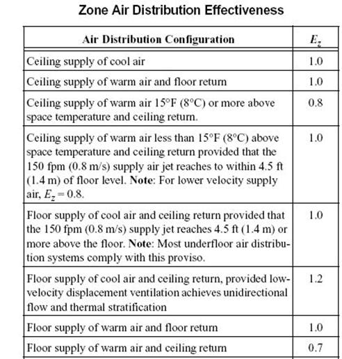
Figure 126. Controller:MechanicalVentilation Zone Air Distribution Effectiveness (Source: ASHRAE Standard 62.1-2007)
This optional field input points to a schedule with values of zone air distribution effectiveness. It provides a more flexible way of specifying zone air distribution effectiveness if it changes with time and/or system operating status and controls. If the schedule is specified, the zone air distribution effectiveness in cooling mode and heating mode will be ignored.
As described previously, the Controller:MechanicalVentilation object works in conjunction with Controller:OutdoorAir. As such, the minimum quantity of outdoor air delivered via the mixed air box will be the greater of:
n the minimum outdoor air flow rate calculated by the fields Minimum Outdoor Air Flow Rate, Minimum Limit and Minimum Outdoor Air Schedule Name in the associated Controller:OutdoorAir object, or
n the outdoor air flow rate calculated by the VRP (details in the Engineering Reference) with inputs specified in this object and the referenced DesignSpecification:OutdoorAir object.
The actual outdoor air flow rate may be higher than the minimum if free cooling is available. Regardless, the outdoor air flow rate will not exceed the Maximum Outdoor Air Flow Rate specified in the associated Controller:OutdoorAir object.
An example input for this object is shown below:
Controller:MechanicalVentilation,
VentObject, !- Name
VentSchedule, !- Availability Schedule Name
Sum, !- Zone Outdoor Air Method
VentilationRateProcedure, !- System Outdoor Air Method
Resistive Zone, !- Zone 1 Name
DSO_Z1, !- Design Specification Outdoor Air Object Name 1
1.0, !- Zone Air Distribution Effectiveness in Cooling Mode 1
1.0, !- Zone Air Distribution Effectiveness in Heating Mode 1
, !- Zone Air Distribution Effectiveness Schedule Name 1
DCV Zone List, !- Zone 2 Name
DSO_ZList, !- Design Specification Outdoor Air Object Name 2
1.2, !- Zone Air Distribution Effectiveness in Cooling Mode 2
0.7, !- Zone Air Distribution Effectiveness in Heating Mode 2
; !- Zone Air Distribution Effectiveness Schedule Name 2
ZoneList,
DCV Zone List, !- Zone List Name
East Zone, !- Zone Name 1
North Zone; !- Zone Name 2
|
|
|
In addition, the outdoor air flow rate may be modified and heat exchange suspended in response to high indoor relative humidities. When the indoor relative humidity exceeds the zone humidistat’s relative humidity set point, high humidity control is activated. When activated, if high humidity control is based on the outdoor air humidity ratio and the outdoor humidity ratio is greater than the indoor humidity ratio, high humidity control is terminated.

Figure 127. Schematic of the ZoneHVAC:EnergyRecoveryVentilator compound object
A unique user-assigned name for the stand alone ERV controller. Any reference to this controller by another object will use this name.
The input for this field is the outdoor air temperature high limit (°C) for economizer operation. If the outdoor air temperature is above this limit, economizer (free cooling) operation is terminated. No input (blank) in this field means that there is no outdoor air temperature high limit control.
The input for this field is the outdoor air temperature low limit (°C) for economizer operation. If the outdoor air temperature is below this limit, economizer (free cooling) operation is terminated. No input (blank) in this field means that there is no outdoor air temperature low limit control.
The input for this field is the outdoor air enthalpy limit (in J/kg) for economizer operation. If the outdoor air enthalpy is above this value, economizer (free cooling) operation is terminated. No input (blank) in this field means that there is no outdoor air economizer limit control.
Input for this field is the outdoor air dewpoint limit (°C) for economizer operation. If the outdoor air dewpoint temperature is above this value, the outdoor airflow rate will be set to the minimum. No input (blank) in this field means that there is no outdoor air dewpoint limit control. This limit applies to the conditions at the Actuated Node regardless of whether or not there are any other components on the outdoor air path upstream of the mixer.
Input for this field is the name of a quadratic or cubic curve which provides the maximum outdoor air humidity ratio (function of outdoor air dry-bulb temperature) for economizer operation. If the outdoor air humidity ratio is greater than the curve’s maximum humidity ratio (evaluated at the outdoor air dry-bulb temperature), the outdoor air flow rate will be set to the minimum. This limit applies to the conditions at the Actuated Node regardless of whether or not there are any other components on the outdoor air path upstream of the mixer. No input (blank) in this field means that there is no electronic enthalpy limit control.
This input establishes whether or not there is a limit control on the exhaust air temperature. The choices are ExhaustAirTemperatureLimit or NoExhaustAirTemperatureLimit. If ExhaustAirTemperatureLimit is chosen, the controller deactivates economizer mode whenever the outdoor air temperature is greater than the exhaust air temperature. If NoExhaustAirTemperatureLimit is chosen, no limit check on the exhaust air temperature is performed.
This input establishes whether or not there is a limit control on the exhaust air enthalpy. The choices are ExhaustAirEnthalpyLimit or NoExhaustAirEnthalpyLimit. If ExhaustAirEnthalpyLimit is chosen, the controller deactivates economizer mode whenever the outdoor air enthalpy is greater than the exhaust air enthalpy. If NoExhaustAirEnthalpyLimit is chosen, no limit check on the exhaust air enthalpy is performed.
This alpha field is the name of a schedule which controls the change in air flow rate based on time-of-day. Schedule values equal to 0 disable this feature. Schedule values greater than 0 activate the economizer. Note that heat exchange between the air streams is suspended when the economizer is active. This schedule can be used with or without the high humidity control option. When an economizer is used in conjunction with the high humidity control option, high humidity control has priority.
This optional choice field establishes whether or not the supply and exhaust air flow rates are modified in response to high indoor relative humidity. Valid choices are Yes and No. If Yes is selected, the supply and exhaust air flow rates may be modified when the indoor relative humidity is above the humidstat set point. If No is selected, this option is disabled and the following three fields are not used. Note that heat exchange between the air streams is suspended during times when high humidity control is active. The default value is No.
This optional input defines the zone name where the humidistat is located. This is the same zone name used in the Zone Control:Humidistat object. This field is required when the High Humidity Control Flag is specified as Yes.
This optional input is the ratio of the modified supply (outdoor) air flow rate to the supply air flow rate specified in the Energy Recovery Ventilator:Stand Alone ERV object. When the high humidity control algorithm determines that the supply air flow rate will be changed (i.e. increased or decreased), the operating supply air flow rate is equal to the supply air flow rate specified in the Energy Recovery Ventilator:Stand Alone ERV object multiplied by this ratio. The minimum value for this field is 0. This field is used to modify both the supply and exhasut air flow rates when high humidity control is active. The supply and exhasut air fan volumetric flow rates must be able to account for the increase in air flow when this input is greater than 1. The default value is 1.
This optional choice field determines if high humidity control is activated based on high indoor relative humidity alone or is activated only when the indoor relative humidity is above the humidstat set point and the outdoor humidity ratio is less than the indoor humidity ratio. Valid choices are Yes and No. If No is selected, high humidity control is active any time the zone humidistat senses a moisture load. If yes is selected, the model also verifies that the outdoor humidity ratio is less than the humidistat’s zone air humidity ratio. This field is used only when the High Humidity Control Flag is specified as Yes. The default value is Yes.
Following is an example input for this stand alone ERV controller object:
ZoneHVAC:EnergyRecoveryVentilator:Controller,
ERV OA Controller 1, !- ERV controller name
19., !- Temperature high limit {C}
14., !- Temperature low limit {C}
, !- Enthalpy high limit {J/kg}
15.55, !- dew point temperature limit (C)
ElectronicEnthalpyCurveA, !- electronic enthalpy limit curve name
NoExhaustAirTemperatureLimit, !- Exhaust air temperature limit
NoExhaustAirEnthalpyLimit, !- Exhaust air enthalpy limit
OutsideAirFlowSchedule, !- Time of Day Economizer Flow Control Schedule Name
Yes, !- High Humidity Control Flag
East Zone, !- Humidistat Control Zone Name
1.2, !- High Humidity Outdoor air Flow Ratio
Yes; !- Control High Indoor Humidity based on Outdoor Humidity Ratio
Curve:Cubic,
ElectronicEnthalpyCurveA, !- Name
0.01342704, !- Coefficient1 Constant
-0.00047892, !- Coefficient2 x
0.000053352, !- Coefficient3 x**2
-0.0000018103, !- Coefficient4 x**3
16.6, !- Minimum Value of x
29.13; !- Maximum Value of x
This group of objects describes the properties and configuration for the evaporative coolers models for the HVAC section.
The direct stage, shown in the figure below, consists of a rigid media evaporative pad, with water recirculated from a reservoir. The water is pumped from the reservoir to a water distribution header, for water feed by gravity from above the media. The evaporative pad provides the area for the adiabatic saturation of the air. While the process provides a lower dry-bulb temperature, the moisture content of the leaving air is higher than the entering condition. The direct stage is used for comfort cooling in a building where adding humidity to the air can be tolerated.
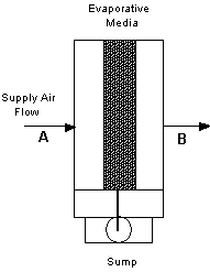
Figure 128. Direct Stage Evaporative Cooler
The thermodynamic process is a simultaneous heat and mass transfer, or adiabatic cooling, and follows a constant enthalpy line on the psychrometric chart, it is shown in the figure below as a process from A to B. Since the deviation of the constant wet-bulb line and the constant enthalpy line is small, it is assumed that the wet-bulb temperature is constant across the direct evaporative stage.
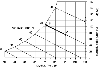
Figure 129. Psychrometric Chart -- Constant Enthalpy
If the direct evaporative process were 100% efficient, the leaving dry-bulb temperature would equal the entering wet-bulb temperature. The efficiency of the direct evaporative process is less than 100% and by defining saturation efficiency (![]() se) for the direct stage or evaporative pad, the leaving dry-bulb temperature can be expressed by the following equation.
se) for the direct stage or evaporative pad, the leaving dry-bulb temperature can be expressed by the following equation.
![]()
A unique identifying name for each evaporative cooler.
The name of a schedule which defines when the evaporative cooler is available.
The face area of the evaporative pad in m2. With the area and mass flow rate, the air velocity is calculated and is used to determine the saturation efficiency.
The depth of the evaporative pad in meters. The pad depth is used to determine the saturation efficiency.
This field is used to specify the power consumed by the evaporative cooler recirculating pump in Watts.
The name of the evaporative cooler air inlet node from the Air Loop Simulation.
The name of the evaporative cooler air outlet node from the Air Loop Simulation.
This input field is currently unused and can be left blank.
This field is optional. It is used to describe where the cooler obtains water used for evaporative cooling. If blank or omitted, then the cooler will obtain water directly from the mains. If the name of a WaterUse:Storage object is used here, then the cooler will obtain its water from that tank. If a tank is specified, the cooler will attempt to obtain all the water it uses from the tank. However if the tank cannot provide all the water the cooler needs, then the cooler will still operate and obtain the rest of the water it needs from the mains.
An IDF example showing how this object is:
EvaporativeCooler:Direct:CelDekPad,
Evaporative Cooler, !- Name
System Availability Schedule, !- Availability Schedule Name
0.6, !- Direct Pad Area {m2}
0.2, !- Direct Pad Depth {m}
225, !- Recirculating Water Pump Power Consumption {W}
Evap Cooler Inlet Node, !- Air Inlet Node Name
Supply Outlet Node; !- Air Outlet Node Name
The output variables that are available for this direct evaporative cooler are shown below:
HVAC,Average, Direct Evap Saturation Efficiency
HVAC,Average, Evap Cooler Electric Power[W]
HVAC,Sum, Evap Cooler Electric Energy[J]
HVAC,Sum, Evap Cooler Water Consumption[m3]
HVAC,Sum,Evap Cooler Mains Water Mains Draw [m3]
HVAC,Sum,Evap Cooler Tank Water Consumption [m3]
HVAC,Sum,Evap Cooler Starved Water Consumption [m3]
HVAC,Sum,Evap Cooler Starved Water Mains Draw [m3]
The saturation efficiency is the temperature change of the supply air divided by the difference between the inlet air dry-bulb and wet-bulb temperatures. In other words, it is a measure of the approach to the inlet air wet-bulb temperature.
These output variables report the electric power and electric energy required to operate the water pump.
The water consumption is the water evaporated from the pad. This water consumption is only from the direct thermodynamics of water evaporation and does not include other sources of consumption such as drift or concentration blow down. This report variable appears when mains water is supplied to the cooler.
This is the source of the water consumed. This report variable appears when mains water is supplied to the cooler.
The water consumption is the water evaporated from the pad. This water consumption is only from the direct thermodynamics of water evaporation and does not include other sources of consumption such as drift or concentration blow down. This report variable appears when storage tank water is supplied to the cooler.
This is the water consumed by the evaporative cooler that could not accually be met by the storage tank. This report variable appears when storage tank water is supplied to the cooler.
This is the source (mains) of water consumed by the evaporative cooler that could not accually be met by the storage tank. This report variable appears when storage tank water is supplied to the cooler.
This cooler is similar in principal to the EvaporativeCooler:Direct:CelDekPad. The model differs in that it gives the user a simple way of specify the cooler effectiveness. Using the ResearchSpecial input object also allows the cooler to control the amount of cooling based on node setpoints (controlled by SetpointManagers). This avoid problems from over cooling when conditions are such that loads are low and cooling power is high. Water pump power is assumed to vary linearly when the cooler is operating at less than full capacity.
A unique identifying name for each cooler.
The name of a schedule that defines when the evaporative cooler is available.
This field specifies the effectiveness that is applied to the wetbulb depression to determine the conditions leaving the cooler. This model assumes that the effectiveness is constant.
This field is used to specify the power consumed by the water pump that circulates water in Watts.
The name of the air inlet node for the primary air flow path through the cooler.
The name of the air outlet node for the primary air flow path through the cooler.
This field specifies the name of a node that will provide system air temperature setpoint information. A separate SetpointManager object should be setup to update this node.
This field is optional. It is used to describe where the cooler obtains water used for evaporative cooling. If blank or omitted, then the cooler will obtain water directly from the mains. If the name of a WaterUse:Storage object is used here, then the cooler will obtain its water from that tank. If a tank is specified, the cooler will attempt to obtain all the water it uses from the tank. However, if the tank cannot provide all the water the cooler needs, then the cooler will still operate and obtain the rest of the water it needs from the mains.
This field is optional and can be used to model additional water consumed by the cooler from drift. Drift is water that leaves the cooling media as droplets and does not evaporate into the process air stream. For example, water may get blown off the evaporative media by winds and escape the air system. The value entered here is a simple fraction of the water consumed by the cooler for normal process evaporation. The amount of drift is this fraction times the water evaporated for the normal cooling process. This field can be left blank and then there will be no added water consumption from drift.
This field is optional and can be used to model additional water consumed by the cooler from blowdown. Blowdown is water that is intentionally drained from the cooler’s sump to offset the build up of solids in the water that would otherwise occur because of evaporation. The value entered here is dimensionless. It can be characterized as the ratio of solids in the blowdown water to solids in the make up water. Typical values are 3 to 5. The default is 3.0.
An example IDF entry is
EvaporativeCooler:Direct:ResearchSpecial,
Direct Evap Cooler, !- Name
ALWAYS_ON, !- Availability Schedule Name
0.7 , !- Cooler Effectiveness
30.0 , !- Recirculating Water Pump Power Consumption
OAIndRDD Evap Cooler- OADirect Evap CoolerNode , !- Air Inlet Node Name
OADirect Evap Cooler- OAMixing BoxNode, !- Air Outlet Node Name
OADirect Evap Cooler- OAMixing BoxNode, !- Sensor Node Name
, !- Water Supply Storage Tank Name
0.0, !- Drift Loss Fraction
3; !- Blowdown Concentration Ratio
The output variables that are available for this direct evaporative cooler are shown below:
HVAC,Average, Evap Cooler Electric Power[W]
HVAC,Sum, Evap Cooler Electric Energy[J]
HVAC,Sum, Evap Cooler Water Consumption[m3]
HVAC,Sum,Evap Cooler Mains Water Mains Draw [m3]
HVAC,Sum,Evap Cooler Tank Water Consumption [m3]
HVAC,Sum,Evap Cooler Starved Water Consumption [m3]
HVAC,Sum,Evap Cooler Starved Water Mains Draw [m3]
These output variables report the electric power and electric energy required to operate the water pump.
The water consumption is the water evaporated from the pad. This water consumption is only from the direct thermodynamics of water evaporation and does not include other sources of consumption such as drift or concentration blow down. This report variable appears when mains water is supplied to the cooler.
This is the source of the water consumed. This report variable appears when mains water is supplied to the cooler.
The water consumption is the water evaporated from the pad. This water consumption is only from the direct thermodynamics of water evaporation and does not include other sources of consumption such as drift or concentration blow down. This report variable appears when storage tank water is supplied to the cooler.
This is the water consumed by the evaporative cooler that could not accually be met by the storage tank. This report variable appears when storage tank water is supplied to the cooler.
This is the source (mains) of water consumed by the evaporative cooler that could not accually be met by the storage tank. This report variable appears when storage tank water is supplied to the cooler.
The dry coil indirect evaporative cooler, shown in the figure below, has a rigid media pad, similar to the direct evaporative stage, where the adiabatic cooling takes place. The secondary air leaves the rigid media pad and enters an air to air heat exchanger where it cools the supply air flowing through the heat exchanger tubes. The moist secondary air is then exhausted to the environment. The secondary air stream has its own fan and consists of a rigid media evaporative pad, with water recirculated from a reservoir. The water is pumped from the reservoir to a water distribution header, for water feed by gravity from above the media. The evaporative pad provides the area for the adiabatic saturation of the air.
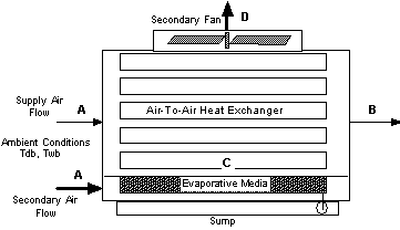
Figure 130. Evaporative Cooler -- Indirect Dry Coil
The process that the secondary air goes through, A to C to D, is shown by the dashed lines in the following figure. Process A to C is adiabatic cooling in the rigid media pad. Then the air enters the shell side of the heat exchanger and is sensibly heated from C to D by the warm supply air passing through the tube side. The secondary air inlet is modeled as a separate stream of outdoor air and the user has the option of defining the name of an outdoor air node.
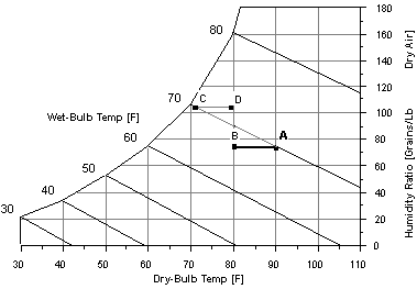
Figure 131. Secondary Air Process -- Indirect Dry Coil Evap Cooler
The advantage of the dry coil heat exchanger is that the heat exchanger does not have the evaporation taking place on the outside of the tubes, thus no mineral deposits are left on the heat exchange surface to reduce the efficiency of the heat exchanger. The rigid media pads are designed to flush the mineral deposits to the sump, so the saturation efficiency of the pad stays relatively constant.
A unique identifying name for each evaporative cooler.
The name of a schedule which defines when the evaporative cooler is available.
The face area of the evaporative pad in m2. With the area and mass flow rate, the air velocity is calculated and is used to determine the saturation efficiency on the secondary side of the evaporative cooler.
The depth of the evaporative pad in meters. The pad depth is used to determine the saturation efficiency on the secondary side of the evaporative cooler.
This field is used to specify the power consumed by the evaporative cooler recirculating pump in Watts.
This field is used to specify the secondary fan flow rate and is specified in m3/sec.
This field is used to specify the efficiency of the fan and is used to calculate the power consumed by the evaporative cooler secondary fan. Input values should be > 0.0 and <= 1.0.
This field is used to specify the delta pressure across the secondary stage of the evaporative cooler in Pascals.
This field is used to specify the effectiveness of the indirect heat exchanger between the primary and secondary air flow.
The name of the evaporative cooler’s primary air inlet node from the Air Loop Simulation. This is the air flow being cooled indirectly.
The name of the evaporative cooler’s primary air outlet node from the Air Loop Simulation.
This input field is currently unused and can be left blank.
This field is optional. It is used to describe where the cooler obtains water used for evaporative cooling. If blank or omitted, then the cooler will obtain water directly from the mains. If the name of a WaterUse:Storage object is used here, then the cooler will obtain its water from that tank. If a tank is specified, the cooler will attempt to obtain all the water it uses from the tank. However if the tank cannot provide all the water the cooler needs, then the cooler will still operate and obtain the rest of the water it needs from the mains.
This field is optional. It is used to explicitly define an outdoor air node for the inlet for secondary air stream. Defining an outdoor air node here allows using the height-dependent model for outdoor air conditions.
And an IDF example showing how this object is specified:
EvaporativeCooler:Indirect:CelDekPad,
IndirectEvapCooler1, !- Name
FanAndCoilAvailSched, !- Availability Schedule Name
0.6, !- Direct Pad Area {m2}
0.2, !- Direct Pad Depth {m}
225., !- Recirculating Water Pump Power Consumption {W}
1.0, !- Secondary Fan Flow Rate {m3/s}
0.7, !- Secondary Fan Efficiency
200.0, !- Secondary Fan Delta Pressure {Pa}
0.67, !- Indirect Heat Exchanger Effectiveness
EvapCoolerIndirectInletAirNode, !- Primary Air Inlet Node Name
EvapCoolerDirectInletAirNode, !- Primary Air Outlet Node Name
, !- Control Type
, !- Water Supply Storage Tank Name
Secondary side OA inlet node; !- Secondary Air Inlet Node Name
The output variables that are available for the indirect dry evaporative cooler are shown below:
HVAC,Average, Indirect Dry Evap Saturation Efficiency
HVAC,Average, Indirect Dry Evap Total Stage Efficiency
HVAC,Average, Evap Cooler Electric Power[W]
HVAC,Sum, Evap Cooler Electric Energy[J]
HVAC,Sum, Evap Cooler Water Consumption[m3]
HVAC,Sum,Evap Cooler Mains Water Mains Draw [m3]
HVAC,Sum,Evap Cooler Tank Water Consumption [m3]
HVAC,Sum,Evap Cooler Starved Water Consumption [m3]
HVAC,Sum,Evap Cooler Starved Water Mains Draw [m3]
The dry evaporation saturation efficiency is the saturation efficiency of the secondary or wet side air stream defined as the temperature change of the supply air divided by the difference between the outdoor dry-bulb and wet-bulb temperatures. In other words, it is a measure of the approach to the outdoor wet-bulb temperature.
The total stage efficiency includes the sensible heat exchanger effectiveness of the heat exchanger in the supply air stream. It is the saturation efficiency multiplied by the heat exchanger effectiveness.
These output variables report the electric power and energy consumed by the secondary air fan and the sump pump.
The water consumption is the water evaporated from the pad. This water consumption is only from the direct thermodynamics of water evaporation and does not include other sources of consumption such as drift or concentration blow down. This report variable appears when mains water is supplied to the cooler.
This is the source of the water consumed. This report variable appears when mains water is supplied to the cooler.
The water consumption is the water evaporated from the pad. This water consumption is only from the direct thermodynamics of water evaporation and does not include other sources of consumption such as drift or concentration blow down. This report variable appears when storage tank water is supplied to the cooler.
This is the water consumed by the evaporative cooler that could not accually be met by the storage tank. This report variable appears when storage tank water is supplied to the cooler.
This is the source (mains) of water consumed by the evaporative cooler that could not accually be met by the storage tank. This report variable appears when storage tank water is supplied to the cooler.
The wetted coil evaporative cooler shown in the figure below, has water sprayed directly on the tubes of the heat exchanger where latent cooling takes place. The vaporization of the water on the outside of the heat exchanger tubes allows the simultaneous heat and mass transfer which removes heat from the supply air on the tube side. Then the moist secondary air is exhausted. The secondary air stream has its own fan.
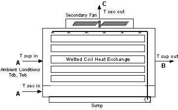
Figure 132. Evaporative Cooler – Indirect Wet Coil
The process that the secondary air goes through, A to C on the following figure, is a path of simultaneous heat and mass transfer, but it does not follow a line of constant enthalpy as in the direct stage. The process is not adiabatic due to the heat gain from the supply air flowing through the tubes of the heat exchanger.
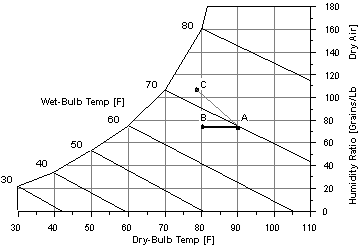
Figure 133. Secondary Air Process – Indirect Wet Coil Evap Cooler
The wet coil heat exchanger can have a higher stage efficiency than the dry coil due to a higher heat transfer rate on the outside of the heat exchanger tubes. Over the operating lifetime of the heat exchanger, the vaporization taking place on the heat exchange surface can leave mineral deposits which will decrease the effectiveness of the heat exchanger.
A unique identifying name for each evaporative cooler.
The name of a schedule which defines when the evaporative cooler is available.
The maximum efficiency of the stage is a combination of the efficiency due to the simultaneous heat and mass transfer on the outside of the tube and the efficiency of the heat exchanger. This value can be higher than the dry coil overall efficiency since the convective coefficients on the outside of the tube are larger.
The Coil Flow Ratio is determined from performance data. The Coil Flow Ratio tells how quickly the efficiency of the stage would decrease with a mismatch of the supply and secondary flows.
This field is used to specify the power consumed by the evaporative cooler recirculating pump in Watts.
This field is used to specify the secondary fan flow rate and is specified in m3/sec.
This field is used to specify the efficiency of the fan and is used to calculate the power consumed by the evaporative cooler secondary fan. Input values should be > 0.0 and <= 1.0.
This field is used to specify the delta pressure across the secondary stage of the evaporative cooler in Pascals.
The name of the evaporative cooler air inlet from the Air Loop Simulation.
The name of the evaporative cooler air outlet from the Air Loop Simulation.
This input field is currently unused and can be left blank.
This field is optional. It is used to describe where the cooler obtains water used for evaporative cooling. If blank or omitted, then the cooler will obtain water directly from the mains. If the name of a WaterUse:Storage object is used here, then the cooler will obtain its water from that tank. If a tank is specified, the cooler will attempt to obtain all the water it uses from the tank. However if the tank cannot provide all the water the cooler needs, then the cooler will still operate and obtain the rest of the water it needs from the mains.
This field is optional. It is used to explicitly define an outdoor air node for the inlet for secondary air stream. Defining an outdoor air node here allows using the height-dependent model for outdoor air conditions.
This field is optional and can be used to model additional water consumed by the cooler from drift. Drift is water that leaves the cooling media as droplets and does not evaporate into the process air stream. For example, water may get blown off the evaporative media by winds and escape the air system. The value entered here is a simple fraction of the water consumed by the cooler for normal process evaporation. The amount of drift is this fraction times the water evaporated for the normal cooling process. This field can be left blank and then there will be no added water consumption from drift.
This field is optional and can be used to model additional water consumed by the cooler from blowdown. Blowdown is water that is intentionally drained from the cooler’s sump to offset the build up of solids in the water that would otherwise occur because of evaporation. The value entered here is dimensionless. It can be characterized as the ratio of solids in the blowdown water to solids in the make up water. Typical values are 3 to 5. The default is 3.0.
And an IDF example showing how this object is specified:
EvaporativeCooler:Indirect:WetCoil,
IndirectEvapCooler1, !- Name
FanAndCoilAvailSched, !- Availability Schedule Name
0.8, !- Coil Maximum Efficiency
0.16, !- Coil Flow Ratio
225., !- Recirculating Water Pump Power Consumption {W}
1.0, !- Secondary Fan Flow Rate {m3/s}
0.7, !- Secondary Fan Efficiency
200.0, !- Secondary Fan Delta Pressure {Pa}
EvapCoolerIndirectInletAirNode, !- Primary Air Inlet Node Name
EvapCoolerDirectInletAirNode, !- Primary Air Outlet Node Name
, !- Control Type
, !- Water Supply Storage Tank Name
Secondary side OA inlet node; !- Secondary Air Inlet Node Name
The output variables that are available for the wet indirect evaporative cooler are shown below:
HVAC,Average, Indirect Wet Evap Total Stage Efficiency
HVAC,Average, Evap Cooler Electric Power[W]
HVAC,Sum, Evap Cooler Electric Energy[J]
HVAC,Sum, Evap Cooler Water Consumption[m3]
HVAC,Sum,Evap Cooler Mains Water Mains Draw [m3]
HVAC,Sum,Evap Cooler Tank Water Consumption [m3]
HVAC,Sum,Evap Cooler Starved Water Consumption [m3]
HVAC,Sum,Evap Cooler Starved Water Mains Draw [m3]
The Total Stage Efficiency is defined as the temperature change of the supply air divided by the difference between the outdoor dry-bulb and wet-bulb temperatures, including the effect of the reduction in flow because of the secondary air stream. In other words, it is a measure of the approach to the outdoor wet-bulb temperature.
These output variables report the electric power and energy that are consumed by the secondary air fan and the sump pump.
The water consumption is the water evaporated from the pad. This water consumption is only from the direct thermodynamics of water evaporation and does not include other sources of consumption such as drift or concentration blow down. This report variable appears when mains water is supplied to the cooler.
This is the source of the water consumed. This report variable appears when mains water is supplied to the cooler.
The water consumption is the water evaporated from the pad. This water consumption is only from the direct thermodynamics of water evaporation and does not include other sources of consumption such as drift or concentration blow down. This report variable appears when storage tank water is supplied to the cooler.
This is the water consumed by the evaporative cooler that could not accually be met by the storage tank. This report variable appears when storage tank water is supplied to the cooler.
This is the source (mains) of water consumed by the evaporative cooler that could not accually be met by the storage tank. This report variable appears when storage tank water is supplied to the cooler.
This cooler is similar in principal to the EvaporativeCooler:Indirect:CelDekPad and EvaporativeCooler:Indirect:WetCoil (see Figure 131, Figure 132, and Figure 133). The model differs in that it gives the user more flexibility to specify the source of secondary air. The cooler effectiveness with respect to wetbulb depression is allowed to go beyond 1.0. Using the ResearchSpecial input object also allows the cooler to control the amount of cooling based on node setpoints (controlled by SetpointManagers). This avoid problems from over cooling when conditions are such that loads are low and cooling power is high. Fan power is assumed to vary linearly when the cooler is operating at less than full capacity.
A unique identifying name for each cooler.
The name of a schedule that defines when the evaporative cooler is available.
This field specifies the maximum effectiveness that is applied to the wetbulb depression to determine the conditions leaving the cooler. This effectiveness is a complicated function of the efficiency with which heat and mass are transferred on the secondary side and the efficiency of heat exchange between the secondary and primary flows. The model assumes that the effectiveness is constant.
Not used in this model.
This field is used to specify the power consumed by the water pump that circulates water in Watts. The pump power and energy consumption is reduced by cycling when the amount of cooling needs to be restricted for control purposes.
This field is used to specify the secondary fan flow rate and is specified in m3/s. This flow rate would typically be similar in magnitude to the flow through the primary side. This field can be autosized. When it is autosized, the program detects if the component is in the main air loop or on an outdoor air path. If it is on the main air loop, then the flow rate is set to the AirLoopHVAC system’s design supply air flow rate (which is the maximum required for heating and cooling). If it is on the outdoor air path, then the flow rate is set to the larger of either the design minimum outdoor air flow rate or one-half of the main air loop design flow rate. The flow rate is used to determine parasitic fan energy and does not impact the modeling of cooler effectiveness. The flow rate (and fan power) is effectively reduced by cycling when the amount of cooling needs to be restricted for control purposes.
This field is used to specify the total efficiency for the secondary fan. This efficiency is used to calculate the energy use for the secondary fan and should be a value >0.0 and <=1.0.
This field is used to specify the pressure difference in Pascals experienced by the secondary fan as it moves air through the wet side of the cooler.
The name of the air inlet node for the primary air flow path through the cooler.
The name of the air outlet node for the primary air flow path through the cooler.
This input field is not used by this model. But using this model does implement controlling of the primary outlet temperature.
This field specifies an effectiveness that is applied to the dewpoint depression to determine a bound for the conditions leaving the cooler. The model uses the warmer of the two temperatures determined from wetbulb depression and dewpoint depression.
This field specifies the name of the node providing air to the secondary/wet side of the cooler. Typically this node could appear in an outdoor air node list or be part of an air system loop.
This field specifies the name of a node that will provide system air temperature setpoint information. A separate SetpointManager object should be setup to update this node.
This field is optional, but can be used to feed two sources of secondary air into the wet side of the cooler. Typical use is to run the air system relief air into the system. The model first uses all of the air flow available from this node and then adds the air flow from the secondary air inlet node to make up the total defined by Secondary Fan Flow Rate.
This field is optional. It is used to describe where the cooler obtains water used for evaporative cooling. If blank or omitted, then the cooler will obtain water directly from the mains. If the name of a WaterUse:Storage object is used here, then the cooler will obtain its water from that tank. If a tank is specified, the cooler will attempt to obtain all the water it uses from the tank. However, if the tank cannot provide all the water the cooler needs, then the cooler will still operate and obtain the rest of the water it needs from the mains.
This field is optional and can be used to model additional water consumed by the cooler from drift. Drift is water that leaves the cooling media as droplets and does not evaporate into the process air stream. For example, water may get blown off the evaporative media by winds and escape the air system. The value entered here is a simple fraction of the water consumed by the cooler for normal process evaporation. The amount of drift is this fraction times the water evaporated for the normal cooling process. This field can be left blank and then there will be no added water consumption from drift.
This field is optional and can be used to model additional water consumed by the cooler from blowdown. Blowdown is water that is intentionally drained from the cooler’s sump to offset the build up of solids in the water that would otherwise occur because of evaporation. The value entered here is dimensionless. It can be characterized as the ratio of solids in the blowdown water to solids in the make up water. Typical values are 3 to 5. The default is 3.0.
An IDF example is shown below:
EvaporativeCooler:Indirect:ResearchSpecial,
Indirect Evap ZN1, !- Name
On_Except_Winter_Night, !- Availability Schedule Name
1.2, !- Cooler Maximum Effectiveness
, !- Cooler Flow Ratio
30, !- Recirculating Water Pump Power Consumption {W}
autosize, !- Secondary Fan Flow Rate {m3/s}
0.7, !- Secondary Fan Efficiency
300, !- Secondary Fan Delta Pressure {Pa}
Mixed Air Node ZN1, !- Primary Air Inlet Node Name
Evap Cooler Outlet Node ZN1, !- Primary Air Outlet Node Name
, !- Control Type
0.9, !- Dewpoint Effectiveness Factor
Purge Air Inlet ZN1, !- Secondary Air Inlet Node Name
Air Loop Outlet Node ZN1,!- Sensor Node Name
Relief Air Outlet Node ZN1; !- Relief Air Inlet Node Name
The output variables that are available for the EvaporativeCooler:Indirect:ResearchSpecial object are shown below:
HVAC,Average,Indirect Wet Evap Total Stage Efficiency
HVAC,Average,Indirect Wet Evap Part Load Fract
HVAC,Average,IEC RDDSpecial Dewpoint Bound
HVAC,Sum,Evap Cooler Electric Energy [J]
HVAC,Average,Evap Cooler Electric Power [W]
HVAC,Sum,Evap Cooler Tank Water Consumption [m3]
HVAC,Sum,Evap Cooler Starved Water Consumption [m3]
HVAC,Sum,Evap Cooler Starved Water Mains Draw [m3]
The Total Stage Efficiency is defined as the temperature change of the supply air divided by the difference between the outdoor dry-bulb and wet-bulb temperatures, including the effect of the reduction in flow because of the secondary air stream. In other words, it is a measure of the approach to the outdoor wet-bulb temperature.
This report variable provides the part load fraction of the indirect cooler. The ResearchSpecial cooler model is able to modulate to meet a temperature set point to avoid over cooling. This report variable is the fraction formed by the ratio of the capacity needed over the maximum cooling capacity available. A value of 1.0 corresponds to full capacity cooling.
This report variable is a flag that indicates if the modeling was based on dewpoint effectivenss rather than wetbulb effectiveness The ResearchSpecial model is usually based on wet-bulb approach, but since values in excess of 1.0 are allowed, there is a secondary constraint imposed by dewpoint. If the dewpoint effectiveness was applied, then this flag variable will have the value 1.0, otherwise it is 0.0.
These output variables report the electric power and energy that are consumed by the secondary air fan and the sump pump.
The water consumption is the water evaporated from the pad. This water consumption is only from the direct thermodynamics of water evaporation and does not include other sources of consumption such as drift or concentration blow down. This report variable appears when mains water is supplied to the cooler.
This is the source of the water consumed. This report variable appears when mains water is supplied to the cooler.
The water consumption is the water evaporated from the pad. This water consumption is only from the direct thermodynamics of water evaporation and does not include other sources of consumption such as drift or concentration blow down. This report variable appears when storage tank water is supplied to the cooler.
This is the water consumed by the evaporative cooler that could not accually be met by the storage tank. This report variable appears when storage tank water is supplied to the cooler.
This is the source (mains) of water consumed by the evaporative cooler that could not accually be met by the storage tank. This report variable appears when storage tank water is supplied to the cooler.
The air-to-air flate plate heat exchanger is an HVAC component typically used for exhaust or relief air heat recovery. The user can choose the flow arrangement type: counter flow, parallel flow, or cross flow with both streams unmixed. The input requires no geometric data. Performance is defined by specifying primary outlet air temperature at nominal (user specified) inlet conditions. In addition, the ratio (h.A)p / (h.A)s at nominal flow needs to be input, where h is the convective heat transfer coefficient, A is the surface area, p stands for primary side, s for secondary side.
If the heat exchanger is operated in conjunction with an outdoor air economizer (economizer lockout set to Yes), the nominal supply air flow rate should be set equal to the minimum outdoor air flow rate specified in the Controller:OutdoorAir. The heat exchanger detects that the economizer is operating by the fact that its inlet air flow rate is greater than its nominal supply air flow rate.
A unique user-assigned name for a particular air-to-air flat plate heat exchanger unit. Any reference to this unit by another object will use this name.
The name of the schedule (ref: Schedule) that denotes whether the unit can run during a given hour. A schedule value greater than 0 (usually 1 is used) indicates that the unit can be on during the hour. A value less than or equal to 0 (usually 0 is used) denotes that the unit must be off for the hour.
The user specified flow arrangement of the heat exchanger. The possible inputs are CounterFlow, ParallelFlow, or CrossFlowBothUnmixed.
This input denotes whether the heat exchanger unit is locked out (bypassed) when the air-side economizer is operating. Both the economizer and high humidity control (Ref. Controller:OutdoorAir) activate the heat exchanger lockout as specified by this input. The input choices are Yes (meaning locked out) or No. The default input for this field is Yes.
The ratio (h.A)p / (h.A)s at nominal flow. h is the surface convective heat transfer coefficient, A is the heat transfer area, and p and s stand for primary side and secondary side respectively. A typical value for this ratio is 1.0.
The nominal primary side air flow rate in cubic meters per second. If the unit is operated in conjunction with an outdoor air economizer this should be equal to the minimum outdoor air flow rate.
The nominal primary side air inlet temperature in Celsius.
The nominal primary side air outlet temperature in Celsius.
The nominal secondary side air flow rate in cubic meters per second.
The nominal secondary side air inlet temperature in Celsius.
The electric consumption rate of the unit in watts. Electric power is considered constant whenever the unit operates. This input can be used to model electric power consumption by controls (transformers, relays, etc.) and/or a motor for a rotary heat exchanger. None of this electric power contributes thermal load to the supply or exhaust air streams. The default value for this field is 0.
The name of the HVAC system node from which the unit draws its primary inlet air.
The name of the HVAC system node to which the unit sends its primary outlet air.
The name of the HVAC system node from which the unit draws its secondary inlet air.
The name of the HVAC system node to which the unit sends its secondary outlet air.
An IDF example:
HeatExchanger:AirToAir:FlatPlate,
OA Heat Recovery 1, !- Name
FanAndCoilAvailSched, !- Availability Schedule Name
CounterFlow, !- Flow Arrangement Type
Yes, !- Economizer Lockout
1.0, !- Ratio of Supply to Secondary hA Values
0.4333, !- Nominal Supply Air Flow Rate {m3/s}
5.0, !- Nominal Supply Air Inlet Temperature {C}
15.0, !- Nominal Supply Air Outlet Temperature {C}
0.4333, !- Nominal Secondary Air Flow Rate {m3/s}
20.0, !- Nominal Secondary Air Inlet Temperature {C}
0.0, !- Nominal Electric Power {W}
Desiccant Process Outlet Node, !- Supply Air Inlet Node Name
Heat Recovery Outlet Node, !- Supply Air Outlet Node Name
Relief Air Outlet Node, !- Secondary Air Inlet Node Name
Heat Recovery Secondary Outlet Node; !- Secondary Air Outlet Node Name
HVAC,Average,Heat Exchanger Sensible Heating Rate[W]
HVAC,Sum,Heat Exchanger Sensible Heating Energy[J]
HVAC,Average,Heat Exchanger Latent Heating Rate[W]
HVAC,Sum,Heat Exchanger Latent Heating Energy[J]
HVAC,Average,Heat Exchanger Total Heating Rate[W]
HVAC,Sum,Heat Exchanger Total Heating Energy[J]
HVAC,Average,Heat Exchanger Sensible Cooling Rate[W]
HVAC,Sum,Heat Exchanger Sensible Cooling Energy[J]
HVAC,Average,Heat Exchanger Latent Cooling Rate[W]
HVAC,Sum,Heat Exchanger Latent Cooling Energy[J]
HVAC,Average,Heat Exchanger Total Cooling Rate[W]
HVAC,Sum,Heat Exchanger Total Cooling Energy[J]
HVAC,Average,Heat Recovery Electric Power[W]
HVAC,Sum,Heat Recovery Electric Consumption[J]
This output is the sensible heating rate of the supply air by the heat exchanger in Watts. This rate is determined using the supply air mass flow rate through the heat exchanger unit, the supply air inlet and outlet conditions, and the specific heat of the inlet supply air. A positive value is reported if the supply air is heated by the heat exchanger, else the rate is set to zero.
This output is the sensible heating energy added to the supply air by the heat exchanger in Joules over the timestep being reported.
This output is the latent heating rate (humidification) of the supply air by the heat exchanger in Watts. This rate is determined by taking the difference between the Heat Exchanger Total Heating Rate and the Heat Exchanger Sensible Heating Rate. A positive value is reported if the supply air is humidified by the heat exchanger, else the rate is set to zero.
This output is the latent heating energy added to the supply air by the heat exchanger in Joules over the timestep being reported.
This output is the total heating rate of the supply air by the heat exchanger in Watts. This rate is determined using the supply air mass flow rate through the heat exchanger unit, and the enthalpy of the supply air entering and leaving the unit. A positive value is reported if the enthalpy of the supply air is increased by the heat exchanger, else the rate is set to zero.
This output is the total heating energy added to the supply air by the heat exchanger in Joules over the timestep being reported. This output is also added to a report meter with ResouceType = EnergyTransfer, EndUseKey = HeatRecoveryforHeating, GroupKey = System (ref. Report Meter).
This output is the sensible cooling rate of the supply air by the heat exchanger in Watts. This rate is determined using the supply air mass flow rate through the heat exchanger unit, the supply air inlet and outlet conditions, and the specific heat of the inlet supply air. A positive value is reported if the supply air is cooled by the heat exchanger, else the rate is set to zero.
This output is the sensible cooling energy added to the supply air by the heat exchanger in Joules over the timestep being reported.
This output is the latent cooling rate (dehumidification) of the supply air by the heat exchanger in Watts. This rate is determined by taking the difference between the Heat Exchanger Total Cooling Rate and the Heat Exchanger Sensible Cooling Rate. A positive value is reported if the supply air is dehumidified by the heat exchanger, else the rate is set to zero.
This output is the latent cooling energy added to the supply air by the heat exchanger in Joules over the timestep being reported.
This output is the total cooling rate of the supply air by the heat exchanger in Watts. This rate is determined using the supply air mass flow rate through the heat exchanger unit, and the enthalpy of the supply air entering and leaving the unit. A positive value is reported if the enthalpy of the supply air is decreased by the heat exchanger, else the rate is set to zero.
This output is the total cooling energy added to the supply air by the heat exchanger in Joules over the timestep being reported. This output is also added to a report meter with ResouceType = EnergyTransfer, EndUseKey = HeatRecoveryforCooling, GroupKey = System (ref. Report Meter).
This output is the electric consumption rate of the unit in Watts. This rate is applicable whenever the unit operates (i.e., whenever the unit is scheduled to be available and supply and exhaust air flows exist).
This output is the electric consumption of the unit in Joules for the timestep being reported. This ouput is also added to a report meter with ResourceType = Electricity, EndUseKey = HeatRecovery, GroupKey = System (ref. Report Meter).
Figure 134. Schematic of the Sensible and Latent Air-to-Air Heat Exchanger
Table 30. Operating Conditions for Defining Heat Exchanger Performance
|
Parameter |
Conditions |
|
|
Heating |
Cooling |
|
|
Entering supply air temperature: Dry-bulb Wet-bulb |
1.7ºC (35ºF) 0.6ºC (33ºF) |
35ºC (95ºF) 26ºC (78ºF) |
|
Entering exhaust air temperature: Dry-bulb Wet-bulb |
21ºC (70ºF) 14ºC (58ºF) |
24ºC (75ºF) 17ºC (63ºF) |
Note: Conditions consistent with the Air-Conditioning and Refrigeration Institute’s (ARI) Standard 1060-2001.
This object models the basic operation of an air-to-air heat exchanger. Heat exchange between the supply and exhaust air streams occurs whenever the unit is scheduled to be available (Availability schedule) and supply/exhaust air flow is present. This heat exchanger object can be used in conjunction with a conventional air-side economizer (i.e., specify ModulateFlow in the Controller:OutdoorAir object), whereby heat exchange is suspended whenever the air-side economizer (or high humidity control) is active (i.e., air flow is fully bypassed around a fixed-plate heat exchanger or the rotation of a rotary heat exchanger is stopped). This object is also able to suspend heat exchange for the purpose of providing free cooling operation in the absence of a conventional air-side economizer (i.e., specify MinimumFlowWithBypass in the Controller:OutdoorAir object).
During winter weather, humid exhaust air entering the heat exchanger can form frost on the cold heat exchanger surfaces, which can reduce air flow and the amount of energy recovery. Several methods are used to control or eliminate frost formation, and the following types can be modeled for this heat exchanger object: supply air preheat, minimum exhaust air temperature, exhaust air recirculation and exhaust only. For preheat frost control, a separate heating coil object must be placed in the supply inlet air stream to keep the air temperature above the frost threshold temperature. The other frost control types are modeled within this object itself (i.e., do not require a separate object to be defined) based on alpha and numeric inputs to this heat exchanger object.
Air-to-air heat exchangers are sometimes controlled to maintain a fixed supply air outlet temperature to avoid overheating when the heat exchanger is heating the supply (primary) air. To model this control in EnergyPlus, a set point manager object is used to establish a temperature set point at the supply air outlet node of the heat exchanger. Wheel speed modulation or plate supply air bypass is used to control the supply air exiting conditions to this set point. The set point for supply air temperature control should be set at the minimum economizer temperature set point if an air-side economizer is also being used by the air system. If frost control and supply air outlet temperature control are used, frost control takes precedence over supply air temperature control (e.g., frost control defrost time fraction is determined as if wheel speed modulation or plate supply air bypass is not used).
To model a sensible and latent air-to-air heat exchanger located in an air loop, the input data file should include the following objects:
· AirLoopHVAC:OutdoorAirSystem
· Controller:OutdoorAir
· OutdoorAir:Mixer
· HeatExchanger:AirToAir:SensibleAndLatent
· Coil:Heating:Water, Coil:Heating:Electric or Coil:Heating:Gas (if preheat frost control is to be modeled)
· SetpointManager:Scheduled (if supply air outlet temperature control is used)
The sensible and latent air-to-air heat exchanger can also be used in a number of other applications, including conditioning outdoor ventilation air and supplying it directly to a zone without an air loop. See object ZoneHVAC:EnergyRecoveryVentilator for further details on this specific application.
A description of each input field for this object is provided below.
A unique user-assigned name for a particular sensible/latent air-to-air heat exchanger. Any reference to this heat exchanger by another object will use this name.
The name of the schedule (ref: Schedule) that denotes whether the unit can operate during a given hour. A schedule value greater than 0 (usually 1 is used) indicates that the unit can operate during the hour. A value less than or equal to 0 (usually 0 is used) denotes that the unit will not operate (i.e., no heat exchange will take place).
The nominal primary side (supply) air flow rate in cubic meters per second. The actual supply and exhaust air flow rates must be between 50% and 130% of this value or a warning will be issued.
The sensible heat exchange effectiveness at the heating condition defined in Table 30 above with both the supply and exhaust air volume flow rates equal to 100% of the nominal supply air flow rate specified in the previous input field. The default value for this field is 0.
The latent heat exchange effectiveness at the heating condition defined in Table 30 with both the supply and exhaust air volume flow rates equal to 100% of the nominal supply air flow rate. Specify this value as 0.0 if the heat exchanger does not transfer latent energy. The default value for this field is 0.
The sensible heat exchange effectiveness at the heating condition defined in Table 30 with both the supply and exhaust air volume flow rates equal to 75% of the nominal supply air flow rate. The default value for this field is 0.
The latent heat exchange effectiveness at the heating condition defined in Table 30 with both the supply and exhaust air volume flow rates equal to 75% of the nominal supply air flow rate. Specify this value as 0.0 if the heat exchanger does not transfer latent energy. The default value for this field is 0.
The sensible heat exchange effectiveness at the cooling condition defined in Table 30 with both the supply and exhaust air volume flow rates equal to 100% of the nominal supply air flow rate. The default value for this field is 0.
The latent heat exchange effectiveness at the cooling condition defined in Table 30 with both the supply and exhaust air volume flow rates equal to 100% of the nominal supply air flow rate. Specify this value as 0.0 if the heat exchanger does not transfer latent energy. The default value for this field is 0.
The sensible heat exchange effectiveness at the cooling condition defined in Table 30 with both the supply and exhaust air volume flow rates equal to 75% of the nominal supply air flow rate. The default value for this field is 0.
The latent heat exchange effectiveness at the cooling condition defined in Table 30 with both the supply and exhaust air volume flow rates equal to 75% of the nominal supply air flow rate. Specify this value as 0.0 if the heat exchanger does not transfer latent energy. The default value for this field is 0.
The name of the HVAC system node from which the unit draws its supply (primary) inlet air.
The name of the HVAC system node to which the unit sends its supply (primary) outlet air.
The name of the HVAC system node from which the unit draws its exhaust (secondary) inlet air.
The name of the HVAC system node to which the unit sends its exhaust (secondary) outlet air.
The electric consumption rate of the unit in watts. Electric power is considered constant whenever the unit operates. This numeric input can be used to model electric power consumption by controls (transformers, relays, etc.) and/or a motor for a rotary heat exchanger. None of this electric power contributes thermal load to the supply or exhaust air streams. The default value for this field is 0.
This alpha field determines if the heat exchanger’s supply air outlet is controlled to a temperature set point when the heat exchanger is heating the supply (primary) air. The choices for this input field are “Yes” or “No”, with the default being “No”. When supply air outlet temperature control is used, the wheel rotational speed modulates or supply air is bypassed around the plate heat exchanger to maintain the desired setpoint temperature. A setpoint manager object is required to establish the desired set point at the supply air outlet node (reference: SetpointManager:Scheduled). When an air-side economizer is also being modeled for this air system, the set point for the supply air outlet temperature control should be equal to the economizer outdoor air temperature lower limit (reference: Controller:OutdoorAir, field Economizer Minimum Limit Dry-Bulb Temperature).
This alpha field denotes the type of heat exchanger being modeled: Plate (e.g., fixed plate) or Rotary (e.g., rotating cylinder or wheel). The default choice for this field is “Plate”. The heat exchanger type affects the modeling of frost control options and supply air outlet temperature control. For rotary heat exchangers, rotational speed is varied to control frost formation or the supply air outlet temperature. For plate exchangers, air bypass around the heat exchanger is used to obtain the desired effect.
This alpha field has four choices: None, ExhaustAirRecirculation, ExhaustOnly and MinimumExhaustTemperature. If this field is left blank, the default frost control type is “None”. For modeling preheat frost control, specify “None” for this input field and insert a separate heating coil object in the supply inlet air stream to keep the air temperature above the desired frost threshold temperature.
ExhaustAirRecirculation: dampers are used to direct exhaust air back into the zone through the supply side of the heat exchanger when the supply (outdoor) air inlet temperature falls below a threshold temperature (defined in the next input field). The fraction of time that exhaust air is circulated through the supply side of the heat exchanger is dependent on the supply (outdoor) air inlet temperature with respect to the threshold temperature, the initial defrost time fraction, and the rate of change of defrost time fraction (see Field: Rate of Defrost Time Fraction Increase). When exhaust air is being recirculated, no supply (outdoor ventilation) air is being provided through the heat exchanger unit (which may or may not be acceptable regarding ventilation for occupants).
ExhaustOnly (supply air bypass): this control cycles off the supply air flow through the heat exchanger for a certain period of time while the exhaust air continues to flow through the exhaust side of the heat exchanger. The fraction of time that the supply flow through the heat exchanger is cycled off is dependent on the supply (outdoor) air inlet temperature with respect to the threshold temperature, the initial defrost time fraction, and the rate of change of defrost time fraction (see Field: Rate of Defrost Time Fraction Increase). When implemented in real applications, provisions are usually made to avoid building depressurization when this frost control is operating (automatic or pressure-operated dampers, or a bypass air damper around the supply side of the heat exchanger). For this frost control type, it is assumed that the supply air is bypassed around the heat exchanger during frost control operation (i.e., the total supply flow is not reduced during defrost, but merely bypassed around the heat exchanger).
MinimumExhaustTemperature: the temperature of the exhaust air leaving the heat exchanger is monitored and the heat exchanger effectiveness is decreased (by slowing heat exchanger rotation or bypassing supply air around the plate exchanger) to keep the exhaust air from falling below the threshold temperature.
This numeric field defines the dry-bulb temperature of air which is used to initiate frost control. The default value is 1.7ºC. For ExhaustAirRecirculation and ExhaustOnly frost control, the threshold temperature defines the supply (outdoor) air inlet temperature below which frost control is active. For MinimumExhaustTemperature frost control, heat exchanger effectiveness is controlled to keep the exhaust air outlet temperature from falling below this threshold temperature value.
The appropriate threshold temperature varies with exhaust (inlet) air temperature and humidity, frost control type, heat exchanger type, and whether the heat exchanger transfers sensible energy alone or both sensible and latent energy (enthalpy). Typical threshold temperatures are provided in Table 31 below. However, it is recommended that the user consult manufacturer’s information for the specific air-to-air heat exchanger being modeled.
Table 31. Typical threshold temperatures
|
Frost control type |
Heat exchanger type |
Energy exchange |
Threshold temperature |
|
Exhaust air recirculation |
Plate |
Sensible-only |
-1.1ºC (30ºF) |
|
Sensible + latent |
-12.2ºC (10ºF) |
||
|
Rotary |
Sensible-only |
-12.2ºC (10ºF) |
|
|
Sensible + latent |
-23.3ºC (-10ºF) |
||
|
Exhaust only |
Plate |
Sensible-only |
-1.1ºC (30ºF) |
|
Sensible + latent |
-12.2ºC (10ºF) |
||
|
Rotary |
Sensible-only |
-12.2ºC (10ºF) |
|
|
Sensible + latent |
-23.3ºC (-10ºF) |
||
|
Minimum exhaust temperature |
Plate |
Sensible-only |
1.7ºC (35ºF) |
|
Sensible + latent |
1.7ºC (35ºF) |
||
|
Rotary |
Sensible-only |
1.7ºC (35ºF) |
|
|
Sensible + latent |
1.7ºC (35ºF) |
||
|
Preheat** |
Plate |
Sensible-only |
-1.1ºC (30ºF) |
|
Sensible + latent |
-12.2ºC (10ºF) |
||
|
Rotary |
Sensible-only |
-12.2ºC (10ºF) |
|
|
Sensible + latent |
-23.3ºC (-10ºF) |
Source: Indoor Humidity Assessment Tool, U.S. Environmental Protection Agency, http://www.epa.gov/iaq/schooldesign/saves.html
** To model preheat frost control, specify frost control type as “None” and place a heating coil in the supply inlet air stream controlled to the keep the air temperature above the frost threshold temperature.
This numeric field defines the fraction of the simulation timestep when frost control will be invoked when the threshold temperature is reached. This field is only used for the ExhaustAirRecirculation and ExhaustOnly frost control types. The value for this field must be ≥ 0 and ≤ 1. The default time fraction is 0.083 (e.g., 5 min / 60 min) which is typical for ExhaustAirRecirculation frost control. Higher initial defrost time fractions (e.g., 0.167 = 10 min / 60 min) are typically required for ExhaustOnly frost control. For best results, the user should obtain this information from the manufacturer.
This numeric field defines the rate of increase in the defrost time fraction as the supply (outdoor) air inlet temperature falls below the threshold temperature. This field is only used for the ExhaustAirRecirculation and ExhaustOnly frost control types. The value for this field must be ≥ 0. The default value is 0.012 (e.g., 0.72 min / 60 min per degree C temperature difference) which is typical for ExhaustAirRecirculation frost control. Higher values (e.g., 0.024 = 1.44 min / 60 min per degree C temperature difference) are typically required for ExhaustOnly frost control. For best results, the user should obtain this information from the manufacturer.
This value is used to determine the total defrost time fraction as follows:
Total defrost time fraction = Initial Defrost Time Fraction +
Rate of Defrost Time Fraction Increase * (Tthreshold – Tsupply air inlet)
The model does not allow the total defrost time fraction to exceed 1.0 or be less than 0.
This input denotes whether the heat exchanger unit is locked out (bypassed for plate type heat exchangers or the rotation is suspended for rotary type heat exchangers) when the air-side economizer is operating. Both the economizer and high humidity control (Ref. Controller:OutdoorAir) activate the heat exchanger lockout as specified by this input. The input choices are Yes (meaning locked out) or No. The default input for this field is Yes.
Following is an example input for this heat exchanger object:
HeatExchanger:AirToAir:SensibleAndLatent,
OA Heat Recovery 1, !- Name
FanAndCoilAvailSched, !- Availability Schedule Name
0.4333, !- Nominal Supply Air Flow Rate {m3/s}
.76, !- Sensible Effectiveness at 100% Heating Air Flow {dimensionless}
.68, !- Latent Effectiveness at 100% Heating Air Flow {dimensionless}
.81, !- Sensible Effectiveness at 75% Heating Air Flow {dimensionless}
.73, !- Latent Effectiveness at 75% Heating Air Flow {dimensionless}
.76, !- Sensible Effectiveness at 100% Cooling Air Flow {dimensionless}
.68, !- Latent Effectiveness at 100% Cooling Air Flow {dimensionless}
.81, !- Sensible Effectiveness at 75% Cooling Air Flow {dimensionless}
.73, !- Latent Effectiveness at 75% Cooling Air Flow {dimensionless}
Outside Air Inlet Node Preheated, !- Supply Air Inlet Node Name
Heat Recovery Outlet Node, !- Supply Air Outlet Node Name
Relief Air Outlet Node, !- Exhaust Air Inlet Node Name
Heat Recovery Secondary Outlet Node, !- Exhaust Air Outlet Node Name
200.0, !- Nominal Electric Power {W}
No, !- Supply Air Outlet Temperature Control
Plate, !- Heat Exchanger Type
None; !- Frost Control Type
HVAC,Average,Heat Exchanger Sensible Heating Rate[W]
HVAC,Sum,Heat Exchanger Sensible Heating Energy[J]
HVAC,Average,Heat Exchanger Latent Heating Rate[W]
HVAC,Sum,Heat Exchanger Latent Heating Energy[J]
HVAC,Average,Heat Exchanger Total Heating Rate[W]
HVAC,Sum,Heat Exchanger Total Heating Energy[J]
HVAC,Average,Heat Exchanger Sensible Cooling Rate[W]
HVAC,Sum,Heat Exchanger Sensible Cooling Energy[J]
HVAC,Average,Heat Exchanger Latent Cooling Rate[W]
HVAC,Sum,Heat Exchanger Latent Cooling Energy[J]
HVAC,Average,Heat Exchanger Total Cooling Rate[W]
HVAC,Sum,Heat Exchanger Total Cooling Energy[J]
HVAC,Average,Heat Recovery Electric Power[W]
HVAC,Sum,Heat Recovery Electric Consumption[J]
HVAC,Average,Heat Recovery Sensible Effectiveness[-]
HVAC,Average,Heat Recovery Latent Effectiveness[-]
HVAC,Average,Heat Recovery Supply Air Bypass Mass Flow [kg/s]
HVAC,Average,Heat Recovery Exhaust Air Bypass Mass Flow [kg/s] HVAC,Average,Heat Recovery Defrost Time Fraction[-]
This output is the sensible heating rate of the supply air by the heat exchanger in Watts. This rate is determined using the supply air mass flow rate through the heat exchanger unit, the supply air inlet and outlet conditions, and the specific heat of the inlet supply air. A positive value is reported if the supply air is heated by the heat exchanger, else the rate is set to zero.
This output is the sensible heating energy added to the supply air by the heat exchanger in Joules over the timestep being reported.
This output is the latent heating rate (humidification) of the supply air by the heat exchanger in Watts. This rate is determined by taking the difference between the Heat Exchanger Total Heating Rate and the Heat Exchanger Sensible Heating Rate. A positive value is reported if the supply air is humidified by the heat exchanger, else the rate is set to zero.
This output is the latent heating energy added to the supply air by the heat exchanger in Joules over the timestep being reported.
This output is the total heating rate of the supply air by the heat exchanger in Watts. This rate is determined using the supply air mass flow rate through the heat exchanger unit, and the enthalpy of the supply air entering and leaving the unit. A positive value is reported if the enthalpy of the supply air is increased by the heat exchanger, else the rate is set to zero.
This output is the total heating energy added to the supply air by the heat exchanger in Joules over the timestep being reported. This output is also added to a report meter with ResouceType = EnergyTransfer, EndUseKey = HeatRecoveryforHeating, GroupKey = System (ref. Report Meter).
This output is the sensible cooling rate of the supply air by the heat exchanger in Watts. This rate is determined using the supply air mass flow rate through the heat exchanger unit, the supply air inlet and outlet conditions, and the specific heat of the inlet supply air. A positive value is reported if the supply air is cooled by the heat exchanger, else the rate is set to zero.
This output is the sensible cooling energy added to the supply air by the heat exchanger in Joules over the timestep being reported.
This output is the latent cooling rate (dehumidification) of the supply air by the heat exchanger in Watts. This rate is determined by taking the difference between the Heat Exchanger Total Cooling Rate and the Heat Exchanger Sensible Cooling Rate. A positive value is reported if the supply air is dehumidified by the heat exchanger, else the rate is set to zero.
This output is the latent cooling energy added to the supply air by the heat exchanger in Joules over the timestep being reported.
This output is the total cooling rate of the supply air by the heat exchanger in Watts. This rate is determined using the supply air mass flow rate through the heat exchanger unit, and the enthalpy of the supply air entering and leaving the unit. A positive value is reported if the enthalpy of the supply air is decreased by the heat exchanger, else the rate is set to zero.
This output is the total cooling energy added to the supply air by the heat exchanger in Joules over the timestep being reported. This output is also added to a report meter with ResouceType = EnergyTransfer, EndUseKey = HeatRecoveryforCooling, GroupKey = System (ref. Report Meter).
This output is the electric consumption rate of the unit in Watts. This rate is applicable whenever the unit operates (i.e., whenever the unit is scheduled to be available and supply and exhaust air flows exist).
This output is the electric consumption of the unit in Joules for the timestep being reported. This ouput is also added to a report meter with ResourceType = Electricity, EndUseKey = HeatRecovery, GroupKey = System (ref. Report Meter).
This output is the average sensible effectiveness of the heat exchanger (excluding bypass air, if any) over the timestep being reported.
This output is the average latent effectiveness of the heat exchanger (excluding bypass air, if any) over the timestep being reported.
This output is the average mass flow rate in kg/second of the supply (primary) air stream that is bypassing the heat exchanger over the timestep being reported. This flow rate is equal to the total supply mass flow rate through the heat exchanger unit minus the amount passing through the supply side of the heat exchanger core.
This output is the average mass flow rate in kg/second of the exhaust (secondary) air stream that is bypassing the heat exchanger over the timestep being reported. This flow rate is equal to the total exhaust mass flow rate through the heat exchanger unit minus the amount passing through the exhaust side of the heat exchanger core.
This output is the average fraction of the reporting timestep when frost control is being implemented.
This desiccant heat exchanger object is an HVAC component used to model both temperature (sensible) and moisture (latent) heat exchange between two air streams (Figure 135). The model assumes balanced air flow through the regeneration and process sides of the heat exchanger (i.e., regeneration and process air volume flow rates and face velocities are the same). Heat exchanger performance is specified through a performance data type object (e.g., HeatExchanger:Desiccant:BalancedFlow:PerformanceDataType1).
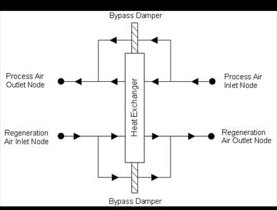
Figure 135. Schematic of the Balanced Flow Desiccant Heat Exchanger
Currently, this desiccant heat exchanger model can be referenced by two compound objects: CoilSystem:Cooling:DX:HeatExchangerAssisted and Dehumidifier:Desiccant:System, both of which are used to provide enhanced dehumidification over conventional systems. If this heat exchanger is referenced by a compound object, the compound object will control heat exchanger operation (i.e., tell the heat exchanger if heat exchange is needed or not for each simulation timestep).
This desiccant heat exchanger object may also be specified directly in an AirLoopHVAC (air loop BranchList) or in an AirLoopHVAC:OutdoorAirSystem (AirLoopHVAC:OutdoorAirSystem:EquipmentList) without being referenced by a compound object. If specified directly in an AirLoopHVAC or AirLoopHVAC:OutdoorAirSystem, then the heat exchanger can be controlled to provide heat exchange based on a maximum and/or minimum humidity set point placed on the process air outlet node (ref. Setpoint Managers). If no humidity set points are provided on this node, then heat exchange will be provided whenever the heat exchanger is available to operate (via its availability schedule) and there is a temperature and/or humidity ratio difference between the two air streams.
Inputs to this model include an availability schedule name, inlet and outlet air node names, and the type and name of the heat exchanger performance data object. A description of each input field for this object is provided below.
A unique, user-assigned name for a particular balanced flow desiccant heat exchanger. Any reference to this heat exchanger by another object will use this name.
The name of the schedule (ref: Schedule) that denotes whether the heat exchanger can operate during a given hour. A schedule value greater than 0 (usually 1 is used) indicates that the heat exchanger can operate during the hour. A value less than or equal to 0 (usually 0 is used) denotes that the heat exchanger will not operate (i.e., no heat exchange will take place).
The name of the HVAC system node from which the unit draws its regeneration inlet air.
The name of the HVAC system node to which the unit sends its regeneration outlet air.
The name of the HVAC system node from which the unit draws its process inlet air.
The name of the HVAC system node to which the unit sends its process outlet air.
This alpha field contains the type of model used to simulate the desiccant heat exchanger’s thermal performance and electrical energy use. Currently, the only valid choice is HeatExchanger:Desiccant:BalancedFlow:PerformanceDataType1.
This alpha field contains the identifying name of the specific heat exchanger performance type object (e.g., HeatExchanger:Desiccant:BalancedFlow:PerformanceDataType1) that defines the performance for this heat exchanger. A single heat exchanger performance type object may be used to define performance for many HeatExchanger:Desiccant:BalancedFlow objects (i.e., the same name may be used in this input field for more than one balanced flow desiccant heat exchanger).
This input denotes whether the heat exchanger unit is locked out (heat exchanger rotation is suspended) when the air-side economizer is operating. Both the economizer and high humidity control (Ref. Controller:OutdoorAir) activate the heat exchanger lockout as specified by this input. The input choices are Yes (meaning locked out) or No. Economizer lockout is typically not used for this type of heat exchanger. For this reason, the default input for this field is No.
Following is an example input for this heat exchanger object:
HeatExchanger:Desiccant:BalancedFlow,
Desiccant Heat Exchanger 1, !- Name
OfficeHeatCoolAvail, !- Availability Schedule Name
DXSystem 1 Mixed Air Node, !- Regeneration Air Inlet Node Name
DX Cooling Coil Air Inlet Node, !- Regeneration Air Outlet Node Name
DX Cooling Coil Air Outlet Node, !- Process Air Inlet Node Name
DXSystem 1 Fan Air Inlet Node, !- Process Air Outlet Node Name
HeatExchanger:Desiccant:BalancedFlow:PerformanceDataType1, !- Heat Exchanger Performance Object Type
HXDesPerf1; !- Heat Exchanger Performance Name
HVAC,Average,Heat Exchanger Sensible Heating Rate[W]
HVAC,Sum,Heat Exchanger Sensible Heating Energy[J]
HVAC,Average,Heat Exchanger Latent Heating Rate[W]
HVAC,Sum,Heat Exchanger Latent Heating Energy[J]
HVAC,Average,Heat Exchanger Total Heating Rate[W]
HVAC,Sum,Heat Exchanger Total Heating Energy[J]
HVAC,Average,Heat Exchanger Sensible Cooling Rate[W]
HVAC,Sum,Heat Exchanger Sensible Cooling Energy[J]
HVAC,Average,Heat Exchanger Latent Cooling Rate[W]
HVAC,Sum,Heat Exchanger Latent Cooling Energy[J]
HVAC,Average,Heat Exchanger Total Cooling Rate[W]
HVAC,Sum,Heat Exchanger Total Cooling Energy[J]
HVAC,Average,Heat Recovery Electric Power[W]
HVAC,Sum,Heat Recovery Electric Consumption[J]
This output is the sensible heating rate of the process air by the heat exchanger in Watts. This rate is determined using the process air mass flow rate through the heat exchanger unit, the process air inlet and outlet temperatures, and the specific heat of the inlet process air. A positive value is reported if the process air is heated by the heat exchanger, else the rate is set to zero.
This output is the sensible heating energy added to the process air by the heat exchanger in Joules over the timestep being reported.
This output is the latent heating rate (humidification) of the process air by the heat exchanger in Watts. This rate is determined by taking the difference between the heat exchanger’s total heat recovery rate and the sensible heat recovery rate. A positive value is reported if the process air is humidified by the heat exchanger, else the rate is set to zero.
This output is the latent heating energy added to the process air by the heat exchanger in Joules over the timestep being reported.
This output is the total heating rate of the process air by the heat exchanger in Watts. This rate is determined using the process air mass flow rate through the heat exchanger unit and the enthalpy of the air entering and leaving the process side of the unit. A positive value is reported if the enthalpy of the process air is increased by the heat exchanger, else the rate is set to zero.
This output is the total heating energy added to the process air by the heat exchanger in Joules over the timestep being reported. This output is also added to a report meter with ResouceType = EnergyTransfer, EndUseKey = HeatRecoveryforHeating, GroupKey = System (ref. Report Meter).
This output is the sensible cooling rate of the process air by the heat exchanger in Watts. This rate is determined using the process air mass flow rate through the heat exchanger unit, the process air inlet and outlet temperatures, and the specific heat of the inlet process air. A positive value is reported if the process air is cooled by the heat exchanger, else the rate is set to zero.
This output is the sensible cooling energy added to the process air by the heat exchanger in Joules over the timestep being reported.
This output is the latent cooling rate (dehumidification) of the process air by the heat exchanger in Watts. This rate is determined by taking the difference between the heat exchanger’s total heat recovery rate and the sensible heat recovery rate. A positive value is reported if the process air is dehumidified by the heat exchanger, else the rate is set to zero.
This output is the latent cooling energy added to the process air by the heat exchanger in Joules over the timestep being reported.
This output is the total cooling rate of the process air by the heat exchanger in Watts. This rate is determined using the process air mass flow rate through the heat exchanger unit and the enthalpy of the air entering and leaving the process side of the unit. A positive value is reported if the enthalpy of the process air is decreased by the heat exchanger, else the rate is set to zero.
This output is the total cooling energy added to the process air by the heat exchanger in Joules over the timestep being reported. This output is also added to a report meter with ResouceType = EnergyTransfer, EndUseKey = HeatRecoveryforCooling, GroupKey = System (ref. Report Meter).
This output is the average electric consumption rate of the unit in Watts. This average rate includes portions of the simulation timestep when the heat exchanger may be cycled off (i.e., average of on and off periods, as appropriate).
This output is the electric consumption of the unit in Joules for the timestep being reported. This ouput is also added to a report meter with ResourceType = Electricity, EndUseKey = HeatRecovery, GroupKey = System (ref. Report Meter).
This object specifies a performance model and model coefficients for a balanced flow desiccant heat exchanger. A HeatExchanger:Desiccant:BalancedFlow object will reference a HeatExchanger:Desiccant:BalancedFlow:PerformanceDataType1 object. This performance data object is used to specify the thermal performance and electric consumption of the heat exchanger. Some representative inputs for this object are provided in the EnergyPlus Reference DataSets (PerfCurves.idf and AllDataSets.idf).
This model predicts the regeneration air stream outlet temperature and humidity ratio values based on the entering regeneration and process air stream temperature, humidity ratio and face velocity. The process air stream outlet humidity ratio and temperatures are calculated based on a simple heat and moisture balance. The model requires that the user enter the nominal volumetric flow rate and a nominal face velocity, electric power consumption, empirical model coefficients for the regeneration outlet air temperature and humidity ratio equations, and the applicable minimum and maximum values for both the independent and dependent variables for the empirical model coefficients provided. This model is based on the following equations:
n The dry-bulb temperature of the regeneration outlet air is defined using the following equation:
![]()
where,
![]() = Regeneration outlet air dry-bulb temperature (C)
= Regeneration outlet air dry-bulb temperature (C)
![]() = Regeneration inlet air humidity ratio (kg/kg)
= Regeneration inlet air humidity ratio (kg/kg)
![]() = Regeneration inlet air dry-bulb temperature (C)
= Regeneration inlet air dry-bulb temperature (C)
![]() = Process inlet air humidity ratio (kg/kg)
= Process inlet air humidity ratio (kg/kg)
![]() = Process inlet air dry-bulb temperature (C)
= Process inlet air dry-bulb temperature (C)
![]() = Regeneration (and process) face velocity (m/s)
= Regeneration (and process) face velocity (m/s)
n The humidity ratio of the regeneration outlet air is defined using the same empirical equation form; however, different coefficients are used as follows:
![]()
where,
![]() = Regeneration outlet air humidity ratio (kg/kg)
= Regeneration outlet air humidity ratio (kg/kg)
n The process outlet air conditions are then calculated based on the regeneration outlet air conditions (temperature or humidity ratio) calculated above, the actual regeneration inlet air conditions entering the heat exchanger, and assuming the same amount of sensible and total energy transfer across both the process and regeneration sides of the heat exchanger. The difference between the actual inlet air conditions and RTI/RWI/PTI/PWI is made here because user-defined limits for RTI/RWI/PTI/PWI may result in a difference between the actual conditions and those used in the equations shown above (see the EnergyPlus Engineering Reference for further discussion).
A description of each input field for this object is provided below.
This alpha field contains the identifying name for this set of desiccant heat exchanger performance data. Any reference to this performance data set by another object (e.g., HeatExchanger:Desiccant:BalancedFlow) will use this name.
The nominal air volume flow rate in cubic meters per second. This model assumes balanced air flow (i.e., the same air volume flow rate across the process and regeneration sides of the heat exchanger). The minimum value should be greater than 0.
This numeric field contains the nominal air velocity across the heat exchanger face area in meters per second. It is assumed that this air velocity is the same for both sides of the heat exchanger. This value, along with the Nominal Air Flow Rate sets the heat exchanger face area. With this fixed face area, the air face velocity is calculated every simulation timestep based on the actual air volume flow rate for the timestep. The minimum value should be greater than 0 and less than or equal to 6.
This numeric field contains the nominal electric consumption rate of the heat exchanger in watts. This electric power is considered constant and is consumed only when the heat exchanger operates (e.g., for all or a portion of the simulation timestep, as appropriate). This numeric input can be used to model electric power consumption by controls (transformers, relays, etc.) and/or a motor for a rotary heat exchanger. None of this electric power contributes thermal load to the process or regeneration air streams. The minimum value should be greater than or equal to 0. The default value for this field is also 0.
The coefficients for the regeneration air outlet temperature equation described above are defined in the following eight fields:
The constant coefficient (B1) in the temperature equation shown above (RTO).
The coefficient (B2) in the temperature equation shown above (RTO).
The coefficient (B3) in the temperature equation shown above (RTO).
The coefficient (B4) in the temperature equation shown above (RTO).
The coefficient (B5) in the temperature equation shown above (RTO).
The coefficient (B6) in the temperature equation shown above (RTO).
The coefficient (B7) in the temperature equation shown above (RTO).
The coefficient (B8) in the temperature equation shown above (RTO).
The following 16 fields are used to establish the valid range for the dependent and independent variables associated with the coefficients defined above (B1 through B8) for the regeneration outlet air temperature equation.
The minimum allowable value of RWI in the temperature equation shown above (kg/kg). Values of RWI less than the minimum will be replaced by this minimum when calculating the regeneration outlet air temperature and a warning message will be issued. The valid range for this input field is 0.0 to 1.0.
The maximum allowable value of RWI in the temperature equation shown above (kg/kg). Values of RWI greater than the maximum will be replaced by this maximum when calculating the regeneration outlet air temperature and a warning message will be issued. The valid range for this input field is 0.0 to 1.0.
The minimum allowable value of RTI in the temperature equation shown above (C). Values of RTI less than the minimum will be replaced by this minimum when calculating the regeneration outlet air temperature and a warning message will be issued.
The maximum allowable value of RTI in the temperature equation shown above (C). Values of RTI greater than the maximum will be replaced by this maximum when calculating the regeneration outlet air temperature and a warning message will be issued.
The minimum allowable value of PWI in the temperature equation shown above (kg/kg). Values of PWI less than the minimum will be replaced by this minimum when calculating the regeneration outlet air temperature and a warning message will be issued. The valid range for this input field is 0.0 to 1.0.
The maximum allowable value of PWI in the temperature equation shown above (kg/kg). Values of PWI greater than the maximum will be replaced by this maximum when calculating the regeneration outlet air temperature and a warning message will be issued. The valid range for this input field is 0.0 to 1.0.
The minimum allowable value of PTI in the temperature equation shown above (C). Values of PTI less than the minimum will be replaced by this minimum when calculating the regeneration outlet air temperature and a warning message will be issued.
The maximum allowable value of PTI in the temperature equation shown above (C). Values of PTI greater than the maximum will be replaced by this maximum when calculating the regeneration outlet air temperature and a warning message will be issued.
The minimum allowable value of RFV in the temperature equation shown above (m/s). Values of RFV less than the minimum will be replaced by this minimum when calculating the regeneration outlet air temperature and a warning message will be issued. The minimum value for this input field should be greater than 0.
The maximum allowable value of RFV in the temperature equation shown above (m/s). Values of RFV greater than the maximum will be replaced by this maximum value when calculating the regeneration outlet air temperature and a warning message will be issued. The minimum value for this input field should be greater than 0.
The minimum value of RTO resulting from the temperature equation shown above (C). If RTO is less than this value, RTO will be replaced by this minimum value and a warning message will be issued.
The maximum value of RTO resulting from the temperature equation shown above (C). If RTO is greater than this value, RTO will be replaced by this maximum value and a warning message will be issued.
The minimum relative humidity of the regeneration inlet air for the temperature equation shown above (percent). If the relative humidity of the regeneration inlet air is below this value, a warning message will be issued. The valid range for this input field is 0.0 to 100.0.
The maximum relative humidity of the regeneration inlet air for the temperature equation shown above (percent). If the relative humidity of the regeneration inlet air is above this value, a warning message will be issued. The valid range for this input field is 0.0 to 100.0.
The minimum relative humidity of the process inlet air for the temperature equation shown above (percent). If the relative humidity of the process inlet air is below this value, a warning message will be issued. The valid range for this input field is 0.0 to 100.0.
The maximum relative humidity of the process inlet air for the temperature equation shown above (percent). If the relative humidity of the process inlet air is above this value, a warning message will be issued. The valid range for this input field is 0.0 to 100.0.
The coefficients for the regeneration outlet air humidity ratio equation are defined in the following eight fields:
The constant coefficient (C1) in the humidity ratio equation shown above (RWO).
The coefficient (C2) in the humidity ratio equation shown above (RWO).
The coefficient (C3) in the humidity ratio equation shown above (RWO).
The coefficient (C4) in the humidity ratio equation shown above (RWO).
The coefficient (C5) in the humidity ratio equation shown above (RWO).
The coefficient (C6) in the humidity ratio equation shown above (RWO).
The coefficient (C7) in the humidity ratio equation shown above (RWO).
The coefficient (C8) in the humidity ratio equation shown above (RWO).
The following 16 fields are used to establish the valid range for the dependent and independent variables associated with the coefficients defined above (C1 through C8) for the regeneration outlet air humidity ratio equation.
The minimum allowable value of RWI in the humidity ratio equation shown above (kg/kg). Values of RWI less than the minimum will be replaced by this minimum when calculating the regeneration outlet air humidity ratio and a warning message will be issued. The valid range for this input field is 0.0 to 1.0.
The maximum allowable value of RWI in the humidity ratio equation shown above (kg/kg). Values of RWI greater than the maximum will be replaced by this maximum when calculating the regeneration outlet air humidity ratio and a warning message will be issued. The valid range for this input field is 0.0 to 1.0.
The minimum allowable value of RTI in the humidity ratio equation shown above (C). Values of RTI less than the minimum will be replaced by this minimum when calculating the regeneration outlet air humidity ratio and a warning message will be issued.
The maximum allowable value of RTI in the humidity ratio equation shown above (C). Values of RTI greater than the maximum will be replaced by this maximum when calculating the regeneration outlet air humidity ratio and a warning message will be issued.
The minimum allowable value of PWI in the humidity ratio equation shown above (kg/kg). Values of PWI less than the minimum will be replaced by this minimum when calculating the regeneration outlet air humidity ratio and a warning message will be issued. The valid range for this input field is 0.0 to 1.0.
The maximum allowable value of PWI in the humidity ratio equation shown above (kg/kg). Values of PWI greater than the maximum will be replaced by this maximum when calculating the regeneration outlet air humidity ratio and a warning message will be issued. The valid range for this input field is 0.0 to 1.0.
The minimum allowable value of PTI in the humidity ratio equation shown above (C). Values of PTI less than the minimum will be replaced by this minimum when calculating the regeneration outlet air humidity ratio and a warning message will be issued.
The maximum allowable value of PTI in the humidity ratio equation shown above (C). Values of PTI greater than the maximum will be replaced by this maximum when calculating the regeneration outlet air humidity ratio and a warning message will be issued.
The minimum allowable value of RFV in the humidity ratio equation shown above (m/s). Values of RFV less than the minimum will be replaced by this minimum when calculating the regeneration outlet air humidity ratio and a warning message will be issued. The minimum value for this input field should be greater than 0.
The maximum allowable value of RFV in the humidity ratio equation shown above (m/s). Values of RFV greater than the maximum will be replaced by this maximum when calculating the regeneration outlet air humidity ratio and a warning message will be issued. The minimum value for this input field should be greater than 0.
The minimum value of RWO resulting from the humidity ratio equation shown above (kg/kg). If RWO is less than this value, RWO will be replaced by this minimum value and a warning message will be issued. The valid range for this input field is 0.0 to 1.0.
The maximum value of RWO resulting from the humidity ratio equation shown above (kg/kg). If RWO is greater than this value, RWO will be replaced by this maximum value and a warning message will be issued. The valid range for this input field is 0.0 to 1.0.
The minimum relative humidity of the regeneration inlet air for the humidity ratio equation shown above (percent). If the relative humidity of the regeneration inlet air is below this value, a warning message will be issued. The valid range for this input field is 0.0 to 100.0.
The maximum relative humidity of the regeneration inlet air for the humidity ratio equation shown above (percent). If the relative humidity of the regeneration inlet air is above this value, a warning message will be issued. The valid range for this input field is 0.0 to 100.0.
The minimum relative humidity of the process inlet air for the humidity ratio equation shown above (percent). If the relative humidity of the process inlet air is below this value, a warning message will be issued. The valid range for this input field is 0.0 to 100.0.
The maximum relative humidity of the process inlet air for the humidity ratio equation shown above (percent). If the relative humidity of the process inlet air is above this value, a warning message will be issued. The valid range for this input field is 0.0 to 100.0.
Following is an example input for this heat exchanger performance data type object:
HeatExchanger:Desiccant:BalancedFlow:PerformanceDataType1,
HXDesPerf1, !- Name
1.05, !- Nominal Air Flow Rate {m3/s}
3.25, !- Nominal Air Face Velocity {m/s}
50.0, !- Nominal Electric Power {W}
-2.53636E+00, !- Temperature Equation Coefficient 1
2.13247E+01, !- Temperature Equation Coefficient 2
9.23308E-01, !- Temperature Equation Coefficient 3
9.43276E+02, !- Temperature Equation Coefficient 4
-5.92367E+01, !- Temperature Equation Coefficient 5
-4.27465E-02, !- Temperature Equation Coefficient 6
1.12204E+02, !- Temperature Equation Coefficient 7
7.78252E-01, !- Temperature Equation Coefficient 8
0.007143, !- Minimum Regeneration Inlet Air Humidity Ratio for Temperature Equation {kg/kg}
0.024286, !- Maximum Regeneration Inlet Air Humidity Ratio for Temperature Equation {kg/kg}
46.111110, !- Minimum Regeneration Inlet Air Temperature for Temperature Equation {C}
46.111112, !- Maximum Regeneration Inlet Air Temperature for Temperature Equation {C}
0.005000, !- Minimum Process Inlet Air Humidity Ratio for Temperature Equation {kg/kg}
0.015714, !- Maximum Process Inlet Air Humidity Ratio for Temperature Equation {kg/kg}
4.583333, !- Minimum Process Inlet Air Temperature for Temperature Equation {C}
21.83333, !- Maximum Process Inlet Air Temperature for Temperature Equation {C}
2.286, !- Minimum Regeneration Air Velocity for Temperature Equation {m/s}
4.826, !- Maximum Regeneration Air Velocity for Temperature Equation {m/s}
35.0, !- Minimum Regeneration Outlet Air Temperature for Temperature Equation {C}
50.0, !- Maximum Regeneration Outlet Air Temperature for Temperature Equation {C}
5.0, !- Minimum Regeneration Inlet Air Relative Humidity for Temperature Equation {percent}
45.0, !- Maximum Regeneration Inlet Air Relative Humidity for Temperature Equation {percent}
80.0, !- Minimum Process Inlet Air Relative Humidity for Temperature Equation {percent}
100.0, !- Maximum Process Inlet Air Relative Humidity for Temperature Equation {percent}
-2.25547E+01, !- Humidity Ratio Equation Coefficient 1
9.76839E-01, !- Humidity Ratio Equation Coefficient 2
4.89176E-01, !- Humidity Ratio Equation Coefficient 3
-6.30019E-02, !- Humidity Ratio Equation Coefficient 4
1.20773E-02, !- Humidity Ratio Equation Coefficient 5
5.17134E-05, !- Humidity Ratio Equation Coefficient 6
4.94917E-02, !- Humidity Ratio Equation Coefficient 7
-2.59417E-04, !- Humidity Ratio Equation Coefficient 8
0.007143, !- Minimum Regeneration Inlet Air Humidity Ratio for Humidity Ratio Equation {kg/kg}
0.024286, !- Maximum Regeneration Inlet Air Humidity Ratio for Humidity Ratio Equation {kg/kg}
46.111110, !- Minimum Regeneration Inlet Air Temperature for Humidity Ratio Equation {C}
46.111112, !- Maximum Regeneration Inlet Air Temperature for Humidity Ratio Equation {C}
0.005000, !- Minimum Process Inlet Air Humidity Ratio for Humidity Ratio Equation {kg/kg}
0.015714, !- Maximum Process Inlet Air Humidity Ratio for Humidity Ratio Equation {kg/kg}
4.583333, !- Minimum Process Inlet Air Temperature for Humidity Ratio Equation {C}
21.83333, !- Maximum Process Inlet Air Temperature for Humidity Ratio Equation {C}
2.286, !- Minimum Regeneration Air Velocity for Humidity Ratio Equation {m/s}
4.826, !- Maximum Regeneration Air Velocity for Humidity Ratio Equation {m/s}
0.007914, !- Minimum Regeneration Outlet Air Humidity Ratio for Humidity Ratio Equation {kg/kg}
0.026279, !- Maximum Regeneration Outlet Air Humidity Ratio for Humidity Ratio Equation {kg/kg}
5.0, !- Minimum Regeneration Inlet Air Relative Humidity for Humidity Ratio Equation {percent}
45.0, !- Maximum Regeneration Inlet Air Relative Humidity for Humidity Ratio Equation {percent}
80.0, !- Minimum Process Inlet Air Relative Humidity for Humidity Ratio Equation {percent}
100.0; !- Maximum Process Inlet Air Relative Humidity for Humidity Ratio Equation {percent}
No variables are reported for this object. However, outputs are provided by the HeatExchanger:Desiccant:BalancedFlow object that references this PerformanceDataType1 object.
Demand limiting, or demand management, is a strategy for reducing a building's demand for utilities, e.g., electricity. Utility companies typically charge a monthly fee for "demand charges" that is based on the peak demand during a certain time period. Often the peak demand charge is set by one exceptional day that is much higher than the peak demand for an average day during the month. Therefore, to save utility costs, it is in the interest of building owners to find ways to manage the demand on peak days. While demand management is generally concerned with the demand for electricity, the future will likely see demand management of other utilities, such as natural gas or water.
Demand limiting controls shut off or reduce the power to non-essential loads in order to reduce the overall building demand. Some typical controls:
§ shut off or dim electric lights, equipment, or HVAC systems
§ reset the thermostatic set points on HVAC systems
§ reduce the load of a set of similar components by rotating one or more components "off" for a short time interval
§ turn on generators to meet some or all of the building's demand.
The demand limiting controls implemented in EnergyPlus are intended to allow some of the more common demand limiting strategies. Currently, only Exterior:Lights, Lights, ElectricEquipment, and ZoneControl:Thermostat objects can be demand limited. Additional components will be demand limited in future releases.
The DemandManagerAssignmentList object is a high level control that makes demand limiting decisions based on a list of possible demand limiting strategies. Each demand limiting strategy is described in a separate DemandManager object. (This is structured like the relationship between the AvailabilityManagerAssignmentList and the AvailabilityManager objects.)
Each DemandManagerAssignmentList monitors and demand limits one meter. Only electricity meters are currently allowed. In many cases, the meter will be Electricity:Facility. A schedule and safety factor are used to set the demand limit above which the DemandManagers become activated. The billing month schedule and demand window are also taken into account when calculating the demand limit.
DemandManagers in the list are activated based on the Demand Manager Priority. If the Sequential option is used, each manager in the list is activated in sequence from first to last until demand is reduced below the limit or until all managers are activated. If the All option is used, all managers are activated simultaneously to achieve the maximum demand reduction.
A DemandManager is skipped if it cannot reduce the demand. Possible reasons that a manager cannot reduce demand include:
§ not enough load to limit
§ not available because of its Availability Schedule
§ already activated; load limited during a previous timestep.
The name of the DemandManagerAssignmentList object.
This field references the meter that is to be monitored and demand limited. Only electricity meters are currently allowed.
The reference to the schedule object specifying the target demand limits [schedule values should be in Watts].
This field is a multiplier that is applied to the target demand limit (above). When the metered demand exceeds (target demand limit * safety fraction), the DemandManagers begin to limit the demand. This helps to ensure that the target limit is not exceeded.
The reference to the schedule object that defines the monthly billing periods. The peak demand during the peak period of the billing period typically determines the demand charge. This should reference the same schedule that is used in the Month Schedule Name field of the UtilityCost:Tariff object. If left blank, it defaults to the regular divisions between months.
The reference to the schedule object that defines the peak/off-peak time-of-use periods. The peak demand during the peak period of the billing period typically determines the demand charge. This should reference the same schedule that is used in the Time of Use Period Schedule Name field of the UtilityCost:Tariff object. A value of 1 indicates the peak period; any other value is off-peak. If left blank, it defaults to always on the peak period. The DemandManagerAssignmentList only attempts to demand limit during peak periods.
This field is similar to the field of the same name in the UtilityCost:Tariff object. However, the user may not want to limit using the same demand window as the utility company. This field allows the user to input the number of minutes over which to calculate the current demand. The minutes are rounded to match the nearest multiple of time steps.
This field indicates what logic should be used to activate the individual DemandManagers in the list. Sequential treats the list of DemandManagers as a sequential priority list, i.e., the first DemandManager in the list is activated first, then the second, etc., until the demand falls below the limit. All activates all demand managers to achieve the maximum demand reduction.
The key word defining the type of DemandManager.
The name of a DemandManager object defined elsewhere in the input file.
DemandManagers are listed by pairs of data items: Demand Manager Type and Demand Manager Name. Ten managers are accomodated in the list by default. The IDD specification, however, is extensible and additional pairs may be added by directly editing the IDD.
An example IDF showing how this object is used is provided below:
DemandManagerAssignmentList,
Demand Manager, !- Name
Electricity:Facility, !- Meter Name
Limit Schedule, !- Demand Limit Schedule Name
1.0, !- Demand Limit Safety Fraction
, !- Billing Period Schedule Name
, !- Peak Period Schedule Name
15, !- Demand Window Length {minutes}
Sequential, !- Demand Manager Priority
DemandManager:ExteriorLights, !- DemandManager 1 Object Type
Ext Lights Manager, !- DemandManager 1 Name
DemandManager:ElectricEquipment, !- DemandManager 2 Object Type
Eq Mgr Stage 1, !- DemandManager 2 Name
DemandManager:ElectricEquipment, !- DemandManager 3 Object Type
Eq Mgr Stage 2, !- DemandManager 3 Name
DemandManager:ElectricEquipment, !- DemandManager 4 Object Type
Eq Mgr Stage 3, !- DemandManager 4 Name
DemandManager:Lights, !- DemandManager 5 Object Type
Lights Manager, !- DemandManager 5 Name
DemandManager:Thermostats, !- DemandManager 6 Object Type
Thermostats Manager; !- DemandManager 6 Name
The following output variables are reported for the DemandManagerAssignmentList object:
Zone,Average,Demand Manager Meter Demand [W]
Zone,Average,Demand Manager Average Demand [W]
Zone,Average,Demand Manager Peak Demand [W]
Zone,Average,Demand Manager Scheduled Limit [W]
Zone,Average,Demand Manager Demand Limit [W]
Zone,Average,Demand Manager Avoided Demand [W]
Zone,Average,Demand Manager Over Limit [W]
Zone,Sum,Demand Manager Over Limit Duration [hr]
Zone,Sum,Demand Manager Exterior Energy Iterations []
Zone,Sum,Demand Manager Heat Balance Iterations []
Zone,Sum,Demand Manager HVAC Iterations []
The current demand for the designated meter.
The current demand for the designated meter averaged over the Demand Window Length.
The peak demand in the billing month so far.
The scheduled target demand limit from the Demand Limit Schedule.
The actual demand limit after multiplication by the Demand Limit Safety Fraction.
The demand that was avoided by the active DemandManagers.
The difference between the demand limit and the average demand.
The number of hours that the demand limit was exceeded.
The number times that the exterior energy use was resimulated for demand limiting.
The number times that the zone heat balance was resimulated for demand limiting.
The number times that the HVAC system was resimulated for demand limiting.
The DemandManager:ExteriorLights object is used for demand limiting Exterior:Lights objects.
The name of the DemandManager:ExteriorLights object.
The reference to the schedule object specifying the availability of this DemandManager.
This field specifies the type of limiting control. The Fixed option reduces the power to the controlled loads by a fixed amount determined by the Maximum Limit Fraction field. The Off option disables the DemandManager in the simulation.
The minimum amount of time [minutes] that the DemandManager will continue to demand limit after being activated. This prevents loads from turning on and off every time step.
This field specifies a fraction of the Design Level power for the load that determines the lowest allowable power level. With Limit Control set to Fixed, the power is reduced to Maximum Limit Fraction * Design Level whenever the manager is activated. For example, if the Maximum Limit Fraction is 0.8, then a 100 W design level load is reduced to 80 W when limiting. A Maximum Limit Fraction of zero means that the load can be shut off entirely.
NOT YET IMPLEMENTED.
This field specifies which loads are selected to be limited. The All option simultaneously limits all of the loads listed in this DemandManager. The RotateMany option limits all loads except for one which rotates sequentially through the loads listed. The RotateOne limits only one load which rotates sequentially through the loads listed. The time interval between rotations is set by the Rotation Duration field.
If the RotateOne or RotateMany option is used for Selection Control, this field sets the time interval [minutes] between rotations.
The names of Exterior:Lights objects defined elsewhere in the input file. These are the loads to be limited by this DemandManager.
Ten objects are accomodated in the list by default. The IDD specification, however, is extensible and additional fields may be added by directly editing the IDD.
An example IDF showing how this object is used is provided below:
DemandManager:ExteriorLights,
Ext Lights Manager, !- Name
, !- Availability Schedule Name
Fixed, !- Limit Control
60, !- Minimum Limit Duration {minutes}
0.0, !- Maximum Limit Fraction
, !- Limit Step Change
All, !- Selection Control
, !- Rotation Duration {minutes}
Exterior Lights; !- Exterior Lights 1 Name
There are no output variables reported for the DemandManager:ExteriorLights object.
The DemandManager:Lights object is used for demand limiting Lights objects.
The name of the DemandManager:Lights object.
The reference to the schedule object specifying the availability of this DemandManager.
This field specifies the type of limiting control. The Fixed option reduces the power to the controlled loads by a fixed amount determined by the Maximum Limit Fraction field. The Off option disables the DemandManager in the simulation.
The minimum amount of time [minutes] that the DemandManager will continue to demand limit after being activated. This prevents loads from turning on and off every time step.
This field specifies a fraction of the Design Level power for the load that determines the lowest allowable power level. With Limit Control set to Fixed, the power is reduced to Maximum Limit Fraction * Design Level whenever the manager is activated. For example, if the Maximum Limit Fraction is 0.8, then a 100 W design level load is reduced to 80 W when limiting. A Maximum Limit Fraction of zero means that the load can be shut off entirely.
NOT YET IMPLEMENTED.
This field specifies which loads are selected to be limited. The All option simultaneously limits all of the loads listed in this DemandManager. The RotateMany option limits all loads except for one which rotates sequentially through the loads listed. The RotateOne limits only one load which rotates sequentially through the loads listed. The time interval between rotations is set by the Rotation Duration field.
If the RotateOne or RotateMany option is used for Selection Control, this field sets the time interval [minutes] between rotations.
The names of Lights objects defined elsewhere in the input file. These are the loads to be limited by this DemandManager.
Ten objects are accomodated in the list by default. The IDD specification, however, is extensible and additional fields may be added by directly editing the IDD.
If a global lights statement is used (Ref: Lights), then only that name need be entered and the demand limiting will be applied to all the zones for that lighting. If only one of a set of zones from a global lights statement is desired, then the name to be entered is: <Zone Name> <Name of Lights Global Object>.
An example IDF showing how this object is used is provided below:
DemandManager:Lights,
Lights Manager, !- Name
, !- Availability Schedule Name
Fixed, !- Limit Control
60, !- Minimum Limit Duration {minutes}
0.5, !- Maximum Limit Fraction
, !- Limit Step Change
All, !- Selection Control
, !- Rotation Duration {minutes}
Space1-1 Lights 1, !- Lights 1 Name
Space2-1 Lights 1, !- Lights 2 Name
Space3-1 Lights 1, !- Lights 3 Name
Space4-1 Lights 1, !- Lights 4 Name
Space5-1 Lights 1; !- Lights 5 Name
There are no output variables reported for the DemandManager:Lights object.
The DemandManager:ElectricEquipment object is used for demand limiting ElectricEquipment objects.
The name of the DemandManager:ElectricEquipment object.
The reference to the schedule object specifying the availability of this DemandManager.
This field specifies the type of limiting control. The Fixed option reduces the power to the controlled loads by a fixed amount determined by the Maximum Limit Fraction field. The Off option disables the DemandManager in the simulation.
The minimum amount of time [minutes] that the DemandManager will continue to demand limit after being activated. This prevents loads from turning on and off every time step.
This field specifies a fraction of the Design Level power for the load that determines the lowest allowable power level. With Limit Control set to Fixed, the power is reduced to Maximum Limit Fraction * Design Level whenever the manager is activated. For example, if the Maximum Limit Fraction is 0.8, then a 100 W design level load is reduced to 80 W when limiting. A Maximum Limit Fraction of zero means that the load can be shut off entirely.
NOT YET IMPLEMENTED.
This field specifies which loads are selected to be limited. The All option simultaneously limits all of the loads listed in this DemandManager. The RotateMany option limits all loads except for one which rotates sequentially through the loads listed. The RotateOne limits only one load which rotates sequentially through the loads listed. The time interval between rotations is set by the Rotation Duration field.
If the RotateOne or RotateMany option is used for Selection Control, this field sets the time interval [minutes] between rotations.
The names of ElectricEquipment objects defined elsewhere in the input file. These are the loads to be limited by this DemandManager.
Ten objects are accomodated in the list by default. The IDD specification, however, is extensible and additional fields may be added by directly editing the IDD.
If a global Electric Equipment statement is used (Ref: ElectricEquipment), then only that name need be entered and the demand limiting will be applied to all the zones for that equipment. If only one of a set of zones from a global electric equipment statement is desired, then the name to be entered is: <Zone Name> <Name of ElectricEquipment Global Object>.
An example IDF showing how this object is used is provided below:
DemandManager:ElectricEquipment,
Eq Mgr Stage 3, !- Name
, !- Availability Schedule Name
Fixed, !- Limit Control
60, !- Minimum Limit Duration {minutes}
0.0, !- Maximum Limit Fraction
, !- Limit Step Change
All, !- Selection Control
, !- Rotation Duration {minutes}
Space5-1 ElecEq 1; !- Electric Equipment 1 Name
There are no output variables reported for the DemandManager:ElectricEquipment object.
The DemandManager:Thermostats object is used for demand limiting ZoneControl:Thermostat objects.
The name of the DemandManager:Thermostats object.
The reference to the schedule object specifying the availability of the DemandManager.
This field specifies the type of limiting control. The Fixed option resets the thermostats to a fixed temperature determined by the Maximum Heating Setpoint Reset and Maximum Cooling Setpoint Reset fields. The Off option disables the DemandManager in the simulation.
The minimum amount of time [minutes] that the DemandManager will continue to demand limit after being activated. This prevents thermostats from resetting on and off every time step.
This field specifies the thermostat heating setpoint temperature [C] that represents the largest allowable temperature reset or setback. With Reset Control set to Fixed, the setpoint temperature is reset to the Maximum Heating Setpoint Reset whenever the manager is activated. For example, if the heating setpoint is normally 22 C and the Maximum Heating Setpoint Reset is 20 C, then the setpoint is reset to 20 C when limiting.
This field specifies the thermostat cooling setpoint temperature [C] that represents the largest allowable temperature reset or setback. With Reset Control set to Fixed, the setpoint temperature is reset to the Maximum Cooling Setpoint Reset whenever the manager is activated. For example, if the cooling setpoint is normally 22 C and the Maximum Cooling Setpoint Reset is 24 C, then the setpoint is reset to 24 C when limiting.
NOT YET IMPLEMENTED.
This field specifies which loads are selected to be limited. The All option simultaneously limits all of the loads listed in this DemandManager. The RotateMany option limits all loads except for one which rotates sequentially through the loads listed. The RotateOne limits only one load which rotates sequentially through the loads listed. The time interval between rotations is set by the Rotation Duration field.
If the RotateOne or RotateMany option is used for Selection Control, this field sets the time interval [minutes] between rotations.
The names of ZoneControl:Thermostat objects defined elsewhere in the input file. These are the loads to be limited by this DemandManager.
Ten objects are accomodated in the list by default. The IDD specification, however, is extensible and additional fields may be added by directly editing the IDD.
If a global thermostat statement is used (Ref: ZoneControl:Thermostat), then only that name need be entered and the demand limiting will be applied to all the zones for that thermostatic control. If only one of a set of zones from a global thermostat statement is desired, then the name to be entered is: <Zone Name> <Name of Thermostat Global Object>.
An example IDF showing how this object is used is provided below:
DemandManager:Thermostats,
Thermostats Manager, !- Name
, !- Availability Schedule Name
Fixed, !- Reset Control
60, !- Minimum Reset Duration {minutes}
19, !- Maximum Heating Setpoint Reset {C}
26, !- Maximum Cooling Setpoint Reset {C}
, !- Reset Step Change
All, !- Selection Control
, !- Rotation Duration {minutes}
SPACE1-1 Control, !- Thermostat 1 Name
SPACE2-1 Control, !- Thermostat 2 Name
SPACE3-1 Control, !- Thermostat 3 Name
SPACE4-1 Control, !- Thermostat 4 Name
SPACE5-1 Control; !- Thermostat 5 Name
There are no output variables reported for the DemandManager:Thermostats object.
This object is used to model the energy losses of transformers when they are used to transfer electricity from the grid to a building (as distribution transformers) or transfer electricity from onsite generators to the grid. Distribution transformers reduce the voltage on utility distribution lines (34.5 kV or less) to a lower secondary voltage (600 V or less) suitable for customer equipment. According to the medium used for cooling and insulation, distribution transformers can be classified into liquid-immersed and dry type transformers. According to the input voltages, distribution transformers can be classified into medium-voltage (between 600 V and 34.5kV) and low-voltage transformer (less than 600 V). The transformers used to output the surplus electricity from onsite generators to the grid usually match the cogeneration voltage to the grid. This object can be used for all types of distribution transformers and the transformers used to output electricity from onsite generators to the grid, but the model defaults applies to the low-voltage dry type transformers because they are the most common type found in commercial and industrial facilities.
Energy losses in transformers consist of the no load (core) loss and the load (winding) loss. The no load loss comes primarily from the switching of the magnetic fields in the core material. It is roughly constant and exists continuously in the core material as long as the transformer is energized. The load loss comes from the electrical resistance in the windings when there is a load on the transformer. The load loss is proportional to the load squared with a small temperature correction. The energy losses at a given load depend on the transformer’s performance. This object provides the user two alternative ways to indicate the transformer’s performance. First, the user can provide the no load loss and load loss at rated conditions. Second, the user can provide the nameplate efficiency and the corresponding reference conditions. The detailed algorithms to calculate the energy losses are described in the Engineering Reference.
The user needs to specify which loads are connected to the transformer. This is achieved in different manners depending on the transformer usage. For a distribution transformer, the user needs to provide a number of electric meters wired to that transformer. The input object can currently accommodate up to ten meters, but it is extensible by modifying the Energy+.idd entry. For a transformer used to output electricity from onsite generators to the grid, the user needs to indicate the transformer name in the served electric load center.
This alpha field contains the schedule name (ref. Schedule) that contains information on the availability of the transformer. A schedule value greater than 0 (usually 1 is used) indicates that the transformer is available to convert AC power from one voltage to another. A value less than or equal to 0 (usually 0 is used) denotes that the transformer is not available.
This field indicates one of the two supported transformer application types: PowerInFromGrid and PowerOutFromOnsiteGeneration. The first type of transformer is used to step down voltage from the electricity grid to a building. The second type of transformer is used to match voltage from building onsite generators to the electricity grid.
This field contains the name of the thermal zone where the transformer is located. Entering a valid name of zone here will direct EnergyPlus to include the transformer’s losses as heat gains to the named thermal zone. If the transformer is not within a thermal zone, this field can be left blank and the thermal energy associated with transformer losses is removed from the building model.
This field contains the fraction of transformer’s losses that enter the zone as long-wave thermal radiation. This numeric filed should have a value between 0.0 and 1.0. The balance of the losses is convective. This field is not used if the previous field for zone name is left blank.
This field defines the rated capacity of the transformer in VA.
This field indicates whether the transformer is a single phase or three phase type. The two alternative values are 1 or 3. The default is 3. This field is currently not used in the model.
This field specifies the winding material used by the transformer. There are two options: Copper and Aluminum. The choice will determine the thermal coefficient of resistance used to calculate the temperature correction factor for the transformer load losses. The default is Aluminum.
This numeric field defines the temperature rise of the windings above the ambient temperature, when the transformer is loaded at its nameplate rating. For liquid-immersed distribution transformers, the full load temperature rise usually takes the value of 65 °C. For dry-type transformers, the temperature rise usually takes three optional values: 80, 115 and 150 °C. This field accepts any value between the minimum (50 °C) and the maximum (180 °C). The default is 150 °C.
This field defines the fraction of load losses resulting from the eddy currents. Transformer’s load losses comprise two parts: the ohmic loss due to the current flowing in the resistance of the windings and the eddy and stray losses due to the eddy currents. This field indicates the fraction of the load losses due to the eddy currents. This numeric field should have a value between 0.0 and 1.0. The default is 0.1.
This alpha field contains the method by which the user will specify the transformer performance: “RatedLosses” or “NominalEfficiency”. If this field is left blank in the input data file, the default input method is assumed to be “RatedLosses”. If the method “NominalEfficiency” is selected, the user must enter the fields for the nameplate efficiency and the corresponding reference coditions as described below. If the method “RatedLosses” is selected, then the fields for rated no load loss and load loss must be entered as described below.
This field defines the no load loss (W) at rated load and conditions. The no load loss is roughly constant and exists whenever the transformer is energized. The no load loss is also called the core loss. This field is used only if the field of Performance Input Method is specified as “RatedLosses”.
This field defines the load loss (W) at rated load and conditions. The load loss varies with the square of the load being served by the transformer. The load loss is also called the winding loss because the load loss occurs in the primary and secondary windings around the core. This field is used only if the field of Performance Input Method is specified as “RatedLosses”.
This field contains the value for transformer efficiency at a given per unit load and specified reference temperature. This field is used only if the field of Performance Input Method is specified as “NominalEfficiency”. The default is 0.98.
This field defines the percentage of the rated capacity at which the nameplate efficiency is measured. According to the NEMA (National Electrical Manufactures Association) Standard TP-1, the per unit load takes the value of 0.35 for dry-type distribution transformers and it takes the value of 0.50 for liquid-filled distribution transformers. The default is 0.35.
This field defines the conductor temperature at which the nameplate efficiency is measured. This field is used only if the field of Performance Input Method is specified as “NominalEfficiency”. According to the NEMA Standard TP-1, the reference temperature takes the value of 75 °C for dry-type distribution transformers and it takes the value of 55 °C for liquid-filled distribution transformers. The default is 75 °C.
This field defines the percentage of the rated capacity at which the maximum efficiency is obtained. This field is used only if the field of Performance Input Method is specified as “NominalEfficiency”. A blank field indicates that it takes the same value as the per unit load for nameplate efficiency.
This field indicates whether the transformer losses are considered to calculate utility cost. In some cases, the transformer losses are required but they are not part of the energy consumption for utility cost calculation. For example, the transformer is owned by the utility company but it locates in the building. In this case, it might be desired to model transformer energy losses for HVAC operation but the energy losses will not be accounted for utility cost.
A transformer may serve different loads such as plug loads, some lighting loads, and some HVAC equipment loads. The user needs to specify which loads are connected to the transformer. This is achieved by providing a list of electric meters wired to the transformer. The input object can currently accommodate up to ten meters, but it is extensible by modifying the Energy+.idd entry. Any valid electric meter name can be used here to wire to the transformer loads. Many different meters are automatically generated by the program and will depend on the objects used throughout the input file. The typical process of determining the exact name to enter in this field involves doing an initial run of EnergyPlus and then examining the *.mdd file which will list the meters and their resulting names. A custom meter is also supported. The meter must have electricity as its resource type.
An example input of the ElectricLoadCenter:Transformer input is:
ElectricLoadCenter:Transformer,
Transformer 1, !-Name
Always On, !- Availability Schedule Name
PowerInFromGrid, !- Transformer Usage
, !- Zone Name
, !- Radiative Fraction
15000, !- Nameplate Rating {VA}
3, !- Phase
Aluminum, !- Conductor Material
150, !- Full Load Temperature Rise {°C}
0.1, !- Fraction of Eddy Current Losses
NominalEfficiency, !- Performance Input Method
, !- Rated No Load Loss {W}
, !- Rated Load Loss {W}
0.985, !- Nameplate Efficiency
0.35, !- Per Unit Load for Nameplate Efficiency
75, !- Reference Temperature for Nameplate Efficiency {°C}
, !- Per Unit Load for Maximum Efficiency
Yes, !- Consider Transformer Loss for Utility Cost
Electricity:Building; !- Meter 1 Name
Schedule:Compact,
Always On, !- Name
Fraction, !- ScheduleType
Through: 12/31, !- Field #1
For: AllDays, !- Field #2
Until: 24:00, !- Field #3
1.0; !- Field #4
HVAC,Average,Transformer Efficiency[]
HVAC,Average,Transformer Power Output[W]
HVAC,Sum,Transformer Energy Output[J]
HVAC,Average,Transformer Power Input[W]
HVAC,Sum,Transformer Energy Input[J]
HVAC,Average,Transformer No Load Loss Rate[W]
HVAC,Sum,Transformer No Load Loss Energy[J]
HVAC,Average,Transformer Load Loss Rate[W]
HVAC,Sum,Transformer Load Loss Energy[J]
HVAC,Average,Transformer Thermal Loss Rate[W]
HVAC,Sum,Transformer Thermal Loss Energy[J]
HVAC,Sum,Energy Consumption for Distribution Transformer[J]
HVAC,Sum,Energy Produced for Cogeneration Transformer[J]
This output field is the efficiency at which the distribution transformer changes alternating current from the higher primary voltage to a lower secondary voltage. The efficiency is calculated for each HVAC system timestep being simulated, and the results are averaged for the timestep being reported.
These outputs are the total electricity power or energy provided by the transformer. They are equal to the metered loads which are wired to the transformer. These values are calculated for each HVAC system timestep being simulated, and the results are averaged (for power) or summed (for energy) for the timestep being reported.
These outputs are the total electricity power or energy fed into the transformer. These values are calculated for each HVAC system timestep being simulated, and the results are averaged (for power) or summed (for energy) for the timestep being reported.
These outputs are the no load loss occurred in the transformer. These values are calculated for each HVAC system timestep being simulated, and the results are averaged (for rate) or summed (for energy) for the timestep being reported.
These outputs are the load loss occurred in the transformer. These values are calculated for each HVAC system timestep being simulated, and the results are averaged (for rate) or summed (for energy) for the timestep being reported.
These outputs are the total energy losses occurred in the transformer. They are equal to the sum of the no load loss and the load loss. These values are calculated for each HVAC system timestep being simulated, and the results are averaged (for rate) or summed (for energy) for the timestep being reported.
This output is the total energy losses occurred in the transformer when it is used for input power from grid to building. It is set as zero if the transformer is used to transfer energy from onsite power generators to the electricity grid. This output is also added to a report meter with ResourceType = Electricity, GroupKey = System.
This output is the total energy losses occurred in the transformer when it is used for input onsite cogeneration to the grid. It is set as zero if the transformer is used to transfer the electricity grid to building. This output is also added to a report meter with ResourceType = ElectricityProduced, EndUseKey = Cogeneration, GroupKey = System.
ElectricLoadCenter:Distribution objects are used to include on-site electricity generators in a simulation. The electric load center dispatches generators according to operation schemes and tracks and reports the amount of electricity generated and purchased. When using on-site generators, the program provides a “net” report where the total electricity used is reduced by the amount generated on site. Electrical demand tracking is done by the internal or custom meters used by EnergyPlus for reporting. The thermal demand tracking uses internal load calculations from the plant simulation. The dispatching of different generators is based on expectations based on their nominal/rated electric power output. If the current conditions are such that the generator model determines that generation was higher or lower, then the results of the dispatch may differ from expectations.
Multiple different ElectricLoadCenter:Distribution objects can be included in an input file. A great deal of flexibility is available by mixing different load centers and operating schemes. If multiple load centers are used, the supervisory control will dispatch generators sequentially across the load centers. Therefore, the order of these input objects in the IDF file becomes important with the generators associated with first load center in the file being the first to be managed. A certain amount of caution is needed to avoid conflicting operating schemes.
The electricity produced from photovoltaic arrays will be reported in the electricity produced report variable and will reduce the demand that the generators will try to meet for that timestep.
This alpha field contains the identifying name for the electric load center.
This alpha field contains the identifying name for the list of generators in the set.
This alpha field specifies the type of operating scheme for the generator set. The available operating schemes are “Baseload,” “DemandLimit,” “TrackElectrical,” “TrackSchedule,“ “TrackMeter,” “FollowThermal,” and “FollowThermalLimitElectrical.” The Baseload scheme operates the generators at their rated (requested) electric power output when the generator is scheduled ON (ref. ElectricLoadCenter:Generators). The Baseload scheme requests all generators scheduled ON (available) to operate, even if the amount of electric power generated exceeds the total facility electric power demand. The DemandLimit scheme limits the amount of purchased electrical from the utility to the amount specified in the input object. The DemandLimit scheme tries to have the generators meet all of the demand above the purchased electric limit set by the user in the next field. The TrackElectrical scheme tries to have the generators meet all of the electrical demand for the building. The TrackSchedule scheme tries to have the generators meet all of the electrical demand determined in a user-defined schedule. The TrackMeter scheme tries to have the generators meet all the electrical demand from a meter, which could also be a user-defined custom meter.
The DemandLimit, TrackElectrical, TrackSchedule, and TrackMeter schemes will sequentially load the available generators. All demand not met by available generator capacity will be met by purchased electrical. Therefore, if DemandLimit, TrackElectrical, TrackSchedule, or TrackMeter is utilized and the available generators are not enough to meet demand, then purchased electrical will offset the difference. If a generator is needed in the simulation for a small load and it is less than the minimum part load ratio the generator will operate at the minimum part load ratio and the excess will either reduce demand or the excess energy will be available for returning to the electric grid.
The FollowThermal and FollowThermalLimitElectrical schemes are for heat following cogeneration and run the generators to meet the thermal demand. The FollowThermal schemes allow excess electrical generation to be exported to the grid, while the FollowThermalLimitElectrical scheme restricts generator output to a maximum of the building’s current electrical demand (so that no electricity is exported). The thermal demand is determined from the plant modeling and depends on the flow requested by other components on the demand side of the plant loop, the loop temperatures, and the loop temperature set point. The electric load center converts the thermal load to an electrical load using a nominal ratio of the thermal to electrical power production for each generator. For these schemes, the generator needs to be connected to the supply side of a plant loop and components that request hot water need to be on the demand side of the plant loop. This is different than the usual configuration for electrical following schemes where the generator is put on the demand side and request flow for the purposes of cooling the generator. Therefore a switch from one of the electrical-based operating schemes to one of the thermal-based operating schemes requires a substantial change in plant topology.
If the load center includes electrical storage, then the choice of operating schemes will also affect how storage is managed.
This numerical field is the user input for the demand limit above which the generators will try and meet the entire electrical load on the building minus the photovoltaic array if available.
This alpha field is the user input for the name of a schedule defined elsewhere in the input file that contains values for the “demand” loads placed on the generator(s). The schedule values should be in Watts.
This alpha field is the user input for the name of a meter. Any valid meter name can be used here to control the loads that the generator(s) will try to meet. Many different meters are automatically generated by the program and will depend on the objects used throughout the input file. The typical process of determining the exact name to enter in this field involves doing an initial run of EnergyPlus and then examining the *.rdd file which will list the meters and their resulting names. The *.mtd file will also be useful to understand what exactly is included in a meter. The user can also use the Output:CustomMeter objects to redefine meter names and to control what electrical loads are included on them in a flexible manner.
This alpha field is used to describe how the electric load center is configured with respect to any power conditioning and/or storage equipment. There are five configurations for load centers available by using one of these keywords:
n AlternatingCurrent
n AlternatingCurrentWithStorage
n DirectCurrentWithInverter
n DirectCurrentWithInverterDCStorage
n DirectCurrentWithInverterACStorage
AlternatingCurrent is the default. All the generators connected to a specific load center need to be of the same type (all AC or all DC). If the generators are DC, then an inverter is needed to convert the DC to AC. If there are DC generators and a DC electrical storage device on the buss along with an inverter, then use DirectCurrentWithInverterDCStorage in this field. See the Engineering Reference for more information including diagrams of the load center configurations.
This field is used to identify the inverter connected to this load center (if any). This field is only used if the Electrical Buss Type is set to DirectCurrentWithInverter and should contain the user-defined name of an inverter object. There are three types of inverter models available—see ElectricLoadCenter:Inverter:Simple, ElectricLoadCenter:Inverter:LookUpTable, or ElectricLoadCenter:Inverter:FunctionOfPower. Enter the name of one of these types of inverter objects defined elsewhere in the input file.
This field is used to identify the electrical storage connected to this load center (if any). This field is only used if the Electrical Buss Type is set to DirectCurrentWithInverterDCStorage or DirectCurrentWithInverterACStorage. Enter the name of an ElectricLoadCenter:Storage:Simple object defined elsewhere in the input file.
This field is used to identify the transformer connected to this load center (if any). This field can be used for any electrical buss types. Enter the name of an ElectricLoadCenter:Transformer object defined elsewhere in the input file.
Examples of this object are:
ElectricLoadCenter:Distribution,
SOFC Electric Load Center, !- Name
Micro-Generators, !- Generator List Name
Baseload, !- Generator Operation Scheme Type
0.0, !- Demand Limit Scheme Purchased Electric Demand Limit {W}
, !- Track Schedule Name Scheme Schedule Name
, !- Track Meter Scheme Meter Name
AlternatingCurrent, !- Electrical Buss Type
, !- Inverter Object Name
; !- Electrical Storage Object Name
ElectricLoadCenter:Distribution,
Electric Load Center, !- Name
Backup Generators, !- Generator List Name
DemandLimit, !- Generator Operation Scheme Type
10000.0, !- Demand Limit Scheme Purchased Electric Demand Limit {W}
, !- Track Schedule Name Scheme Schedule Name
, !- Track Meter Scheme Meter Name
AlternatingCurrent, !- Electrical Buss Type
, !- Inverter Object Name
; !- Electrical Storage Object Name
There are three levels of results reporting related to electric load centers and generators. The top level of reporting provides results across the whole building and all the different electric load centers and generators. The second level of reporting provides results for individual load centers. The third level is for each type of generator (see individual generator descriptions). This section discusses the first two levels.
The whole-building summary report variables are:
HVAC,Average,Total Electric Power Produced [W]
HVAC,Sum,Total Electric Energy Produced [J]
HVAC,Average,Total Electric Power Purchased [W]
HVAC,Sum,Total Electric Energy Purchased [J]
HVAC,Average,Total Building Electric Demand [W]
HVAC,Average,Total HVAC Electric Demand [W]
HVAC,Average,Total Electric Demand [W]
These report variables all use a default keyword “Whole Building.”
These report variables can also be accessed without specifying generation equipment by including the syntax shown below:
ElectricLoadCenter:Distribution,
Electric Load Center; !- Name
Even if no ElectricLoadCenter:Distribution object is included, these report variables are also available for all simulations that have any electricity consuming equipment with the default keyword name “Electrical Service.”
These outputs are the total generator and photovoltaic electricity produced on-site for the entire model, and they are in both Power and Energy units. When electrical storage is used with on-site production, the electricity put into storage is decremented from production and the electricity removed storage is added to production. This means that losses from a round trip through electrical storage decrease on-site electricity production.
These outputs are the total of electricity purchased for the entire model in both Power and Energy units. This value is always positive and indicates the amount of energy is purchased from the utility.
This output is the excess electricity produced and sent out to the electrical grid. This value is always positive and indicates the surplus electricity from generation that exceeds whole-building demand and fed into the grid.
This report variable includes all of the electric demand from the building (non-HVAC) portion of the simulation, which would contain lights, electrical equipment, exterior lights and equipment, etc.
This report variable includes all of the electric demand from the HVAC portion of the simulation, which would contain fans, electric coils, pumps, chillers, cooling towers, etc.
This is the total of the whole Building and HVAC electric demands.
These outputs are the net electricity purchased in both Power and Energy units. This value can be either positive or negative. Positive values are defined as electricity purchased from the utility. Negative values are defined as surplus electricity fed back into the grid.
Each ElectricLoadCenter also collects results from the individual generators that are connected to that load center. The report variables available at the ElectricLoadCenter level are:
HVAC,Average,Load CenterElectric Power Request [W]
HVAC,Average,Load Center Electric Power Produced [W]
HVAC,Sum,Load Center Electric Energy Produced [J]
HVAC,Average,Load Center Thermal Power Produced [W]
HVAC,Sum,Load Center Thermal Energy Produced [J]
This report variable is the average electric power supply (in watts) requested by the load center from its generators for the time step being reported. For the baseload operating scheme, this output variable should equal the sum of the power supply requests for the ‘available’ generators associated with this load center (ref. ElectricLoadCenter:Generators). In other cases, this output could be different from the sum of the power supply requests for the generators associated with this load center. For example, a generator might be requested to provide a certain amount of power but can only provide a fraction of the requested amount. In this case the load center will detect this shortfall and include it when calculating the power request for the next available generator. Therefore, the sum of the power supply requests for the individual generators associated with this load center (ref. ElectricLoadCenter:Generators) could be greater than the Load Center Electric Power Request report variable.
These outputs are the sum of electrical energy and power produced by the generators attached to a particular load center. The keywords for these reports are the unique names of ElectricLoadCenter:Distribution objects.
These outputs are the sum of the thermal energy and power produced by the generators attached to a particular load center. The keywords for these reports are the unique names of ElectricLoadCenter:Distribution objects.
The ElectricLoadCenter:Generators object is used to provide a list of the generators to include in the simulation. The list includes the names and types of all the generators along with separate availability schedules, the rated power output, and thermal-to-electrical power ratio for each. Sets of five input fields are repeated for each generator. If more than 30 generators are needed, EnergyPlus will “auto-extend” to suit the needs but other interfaces (such as the IDF Editor may not). The user can always modify the Energy+.idd file to accommodate the extra fields necessary, but it is likely the next release of EnergyPlus will overwrite any user modifications.
This alpha field contains the identifying name for the generators in the set.
Each generator is specified by a set of 5 input fields that contain an identifying name, a keyword that indicates the type of generator, the rated output of the generator, the availability schedule of the generator, and the thermal to electrical power production ratio.
This alpha field contains the identifying name for the first generator in the list.
This alpha field contains the keyword for the type of generator. The available types include:
n Generator:InternalCombustionEngine
n Generator:CombustionTurbine
n Generator:Photovoltaic
n Generator:FuelCell
n Generator:MicroCHP
n Generator:MicroTurbine
n Generator:WindTurbine
These keywords are the names of the input objects for the type of generator.
This numeric field contains the nominal electric power output to be requested from generator 1. It is normally equal to the rated power output of the generator in Watts. This value is used only for supervisory control and generator dispatch; the actual power output for each time step is determined by the generator models. This value affects how much a generator is loaded (i.e., requested electric power output) and can also impact the operation of an electric storage unit (e.g., LoadCenter:Storage:Simple) if one is connected to the associated load distribution center (ref. ElectricLoadCenter:Distribution). Refer to Electrical Storage in the EnergyPlus Engineering Reference for more details regarding this input field and its relationship with electric storage.
This alpha field is used as an identifying field for the generator availability schedule. This field should contain the name of a schedule defined elsewhere in the input file. A schedule value of <=0.0 indicates the generator is not available, while a schedule value > 0.0 indicates that the generator is available to operate.
This numeric field contains the ratio of the rated thermal output to the rated electric output. It is only needed and used if the operation scheme is set to FollowThermal or FollowThermalLimitElectrical. This nominal ratio is only used for control and dispatch decisions. This value should be generally consistent with the more detailed performance input for the individual generator component models but it is not used in those component models.
An example IDF showing how this object is used is provided below:
ElectricLoadCenter:Generators,
Backup Generators, !- Name
Cat Diesel, !- Generator 1 Name
Generator:InternalCombustionEngine, !- Generator 1 Object Type
50000, !- Generator 1 Rated Electric Power Output
ON PEAK GENERATOR SCHEDULE, !- Generator 1 Availability Schedule Name
, !- Generator 1 Rated Thermal to Electrical Power Ratio
Solar Turbine, !- Generator 2 Name
Generator:CombustionTurbine, !- Generator 2 Object Type
30000, !- Generator 2 Rated Electric Power Output
OFF PEAK GENERATOR SCHEDULE, !- Generator 2 Availability Schedule Name
, !- Generator 2 Rated Thermal to Electrical Power Ratio
Capstone C65, !- Generator 3 Name
Generator:Microturbine, !- Generator 3 Object Type
65000, !- Generator 3 Rated Electric Power Output
MID PEAK GENERATOR SCHEDULE, !- Generator 3 Availability Schedule Name
; !- Generator 3 Rated Thermal to Electrical Power Ratio
A single output variable is available for each generator specified via this object as described below:
HVAC,Average,Generator Power Supply Request [W]
This output variable represents the average electric power supply in Watts that is being requested from a specific generator for the time step being reported. In some instances the output value may be the Rated Electric Power Output specified for the generator in the ElectricLoadCenter:Generators object. If the generator is not available for a simulation time step (as indicated by its availability schedule), then the power supply request will be zero. The power supply request may be less than the rated electric power output if the overall electric power reduction target has already been met, partially or completely, by electric power produced by other generators. If an EnergyPlus Energy Management System is used to specify an electric power supply request for this generator, then that EMS request will be reflected in this output variable.
This input object is used to model conversion from Direct Current (DC) to Alternating Current (AC) in an electric load center that contains photovoltaic modules. Such a load center has an array of photovoltaic modules that feed an inverter DC power and the inverter produces AC power. This input object is for the simplest inverter model and uses a fixed efficiency. There are two other types of inverters with more complex models described below.
This field contains a unique name for the inverter. The name entered must also be unique across all other types of inverters that may also be in the input file.
This field contains the name of a schedule that describes when the inverter is available. If the inverter is scheduled to not be available, by scheduling a value of 0, then it cannot produce AC power and will not consume ancillary power during standby. Any non-zero schedule value means the inverter is available to produce AC power and consume ancillary power during standby. If the Inverter is schedule to be unavailable but it is being supplied with DC power anyway, then the energy is dissipated as heat.
This field contains the name of the thermal zone where the inverter is located. Entering a valid name of zone here will direct EnergyPlus to include the inverter’s losses as heat gains to the named thermal zone. If the inverter is not within a thermal zone, then this field can be left blank (and the thermal energy associated with inverter losses is removed from the building model).
This field contains the fraction of inverter thermal losses that enter the zone as long-wave thermal radiation. This should be a factor between 0.0 and 1.0. The balance of the losses is convective. This field is not used if the previous field for zone name is left blank.
This field contains the value for inverter efficiency. In the simple model, efficiency is a constant. This is the so-called 1-term model. Input data for different types of inverters is available at http://www.gosolarcalifornia.org/equipment/inverter_tests/summaries where the “CEC Efficiency” would be the value to enter here.
An example IDF showing how this object is used is provided below:
ElectricLoadCenter:Inverter:Simple,
Simple Ideal Inverter, !- Name
Always On, !- Availability Schedule Name
, !- Zone Name
0.0, !- Radiative Fraction
1.0; !- Inverter Efficiency
This input object is used to model conversion from Direct Current (DC) to Alternating Current (AC) in an electric load center that contains photovoltaic modules. Such a load center has an array of photovoltaic modules that feed an inverter DC power and the inverter produces AC power. This input object is for an inverter model where efficiency is a function of normalized power.
This field contains a unique name for the inverter. The name entered must also be unique across all other types of inverters that may also be in the input file.
This field contains the name of a schedule that describes when the inverter is available. If the inverter is scheduled to not be available, by scheduling a value of 0, then it cannot produce AC power, nor contribute heat gains to the zone, and will not consume ancillary power during standby. Any non-zero schedule value means the inverter is available to produce AC power, contribute heat gains to the zone and consume ancillary power during standby.
This field contains the name of the thermal zone where the inverter is located. Entering a valid name of zone here will direct EnergyPlus to include the inverter’s losses as heat gains to the named thermal zone. If the inverter is not within a thermal zone, then this field can be left blank (and the thermal energy associated with inverter losses is removed from the building model).
This field contains the fraction of inverter thermal losses that enter the zone as long-wave thermal radiation. This should be a factor between 0.0 and 1.0. The balance of the losses is convective. This field is not used if the previous field for zone name is left blank.
This field contains the name of curve representing the relationship between DC power input into the inverter and the efficiency with which that power is converted to AC. The curve can be either a Curve:Linear, Curve:Quadratic, or Curve:Cubic. The curve’s “x” value is DC power input normalized by the following field. The result of the curve should be power conversion efficiency expressed as a fraction between 0.0 and 1.0.
This field contains the rated power input in watts. This is value used to normalize input power for use with the curve named in the previous field. This is DC power from the PV arrays going into the inverter.
This field contains a minimum bound on the inverter efficiency. This value will be used as a limit on the curve’s result.
This field contains a maximum bound on the inverter efficiency. This value will be used as a limit on the curve’s result.
This field contains a lower limit on the AC power produced by the inverter. If the resulting power output would be below this level, then the inverter is assumed to not produce any power and is in stand by mode. All DC power input is lost (unless it is going into storage).
This field contains an upper limit on the AC power produced by the inverter. If the resulting power output would be above this level, then the power produced is capped at this level with the rest of input power converted to losses (unless it is going into storage).
This field contains the ancillary power in watts used by the inverter when not producing AC power. This is AC electricity consumed in standby mode. Standby mode occurs when the inverter is scheduled to be available but the incoming DC power is too low.
An example IDF showing how this object is used is provided below:
ElectricLoadCenter:Inverter:FunctionOfPower,
Curve Inverter, !- Name
ALWAYS_ON, !- Availability Schedule Name
, !- Zone Name
0.3, !- Radiative Fraction
Inverter Curve, !- Efficiency Function of Power Curve Name
15000, !- Rated Maximum Continuous Input Power {W}
0.0, !- Minimum Efficiency
1.0, !- Maximum Efficiency
200, !- Minimum Power Output {W}
20000, !- Maximum Power Output {W}
0.0; !- Ancillary Power Consumed In Standby {W}
This input object is used to model conversion from Direct Current (DC) to Alternating Current (AC) in an electric load center that contains photovoltaic modules. Such a load center has an array of photovoltaic modules that feed an inverter DC power and the inverter produces AC power. This input object is for an inverter model where efficiency is interpolated using a look up table.
This object was designed for use with data contained in the Inverter Performance Test Summaries available at http://www.gosolarcalifornia.org/equipment/inverter_tests/summaries. All of the data needed for this object can be found there by make and model of inverter. The core of the data set is a 3x6 matrix of efficiency at different voltage and power levels. These form the look up table used in the model. Note that EnergyPlus’ PV models currently model only power and not the voltage and current situation. Therefore, only the nominal voltage data are used. This is the middle row of data in the Go Solar summaries.
This field contains a unique name for the inverter. The name entered must also be unique across all other types of inverters that may also be in the input file.
This field contains the name of a schedule that describes when the inverter is available. If the inverter is scheduled to not be available, by setting a value of 0, then it cannot produce AC power, nor contribute heat gains to the zone, and will not consume ancillary power during standby. Any non-zero schedule value means the inverter is available to produce AC power, contribute heat gains to the zone and consume ancillary power during standby.
This field contains the name of the thermal zone where the inverter is located. Entering a valid name of zone here will direct EnergyPlus to include the inverter’s losses as heat gains to the named thermal zone. If the inverter is not within a thermal zone, then this field can be left blank (and the thermal energy associated with inverter losses is removed from the building model).
This field contains the fraction of inverter thermal losses that enter the zone as long-wave thermal radiation. This should be a factor between 0.0 and 1.0. The balance of the losses is convective. This field is not used if the previous field for zone name is left blank.
This field contains the rated maximum continuous output power in watts.
This field contains the “night tare loss” in watts. This is modeled as ancillary power consumed during standby.
This field contains the nominal DC input voltage in volts. This is “Vnom” in the Go Solar test summaries.
This field contains the fractional efficiency at nominal voltage and 10% power.
This field contains the fractional efficiency at nominal voltage and 20% power.
This field contains the fractional efficiency at nominal voltage and 30% power.
This field contains the fractional efficiency at nominal voltage and 50% power.
This field contains the fractional efficiency at nominal voltage and 75% power.
This field contains the fractional efficiency at nominal voltage and 100% power.
An example IDF showing how this object is used is provided below:
ElectricLoadCenter:Inverter:LookUpTable,
PV Inverter, !- Name
ALWAYS_ON, !- Availability Schedule Name
, !- Zone Name
0.25, !- Radiative Fraction
14000, !- Rated Maximum Continuous Output Power {W}
200.0, !- Night Tare Loss Power {W}
368, !- Nominal Voltage Input {V}
0.839, !- Efficiency at 10% Power and Nominal Voltage
0.897, !- Efficiency at 20% Power and Nominal Voltage
0.916, !- Efficiency at 30% Power and Nominal Voltage
0.931, !- Efficiency at 50% Power and Nominal Voltage
0.934, !- Efficiency at 75% Power and Nominal Voltage
0.930; !- Efficiency at 100% Power and Nominal Voltage
Each inverter can report the following seven output variables.
HVAC,Average,Inverter DC to AC Efficiency [ ]
HVAC,Average,Inverter DC Power Input [W]
HVAC,Sum,Inverter DC Energy Input [J]
HVAC,Average,Inverter AC Power Output [W]
HVAC,Sum,Inverter AC Energy Output [J]
HVAC,Average,Inverter Thermal Loss Rate [W]
HVAC,Sum,Inverter Thermal Loss Energy [J]
This is the efficiency with which DC power is converted to AC power by the inverter.
These outputs are total electricity power or energy fed into the inverter. This is Direct Current from photovoltaics (or DC-based electrical storage) going into the inverter.
These outputs are the total electricity power or energy produced by the inverter. This is Alternating Current going out of the inverter.
These outputs are the thermal power or energy losses in the inverter that stem from converting from DC to AC.
These outputs are the Alternating Current electricity consumed by the inverter. These are ancillary, or night tare loss, power uses by the inverter and modeled as if powered by the building’s grid connection. These ancillary power draws generally occur when the inverter is not generating power but waiting in a standby mode ready to begin generating power.
This input object is used to model storage of electricity in an electric load center. This is a simple model that does not attempt to represent any of the characteristics of a real storage device such as a battery. The type of power, AC or DC, depends on the configuration chosen as the Electrical Buss Type in the ElectricLoadCenter:Distribution object.
This field contains a unique name for the electric storage device.
This field contains the name of a schedule that describes when the storage device is available. If storage is not available, by scheduling a value of 0, then no electrical energy can be stored or drawn from the device. Any non-zero schedule value means the devices is available.
This field contains the name of the thermal zone where the storage device is located. Entering a valid name of a zone here will direct EnergyPlus to include the storage losses as heat gains to the name thermal zone. If the storage is not within a therma zone, then this field can be left blank.
This field contains the fraction of storage losses that enter the zone as long-wave thermal radiation. This should be a factor between 0.0 and 1.0. The balance of the losses are convective. This field is not used if the previous field for zone name is left blank.
This field contains the charging efficiency. This is the energetic efficiency of storing electrical energy in the storage device. A value of 1.0 means the device does not lose any energy when charging.
This field contains the discharging efficiency. This is the energetic efficiency of drawing electrical energy from the storage device. A value of 1.0 means the device does not lose any energy when drawing power.
This field describes the maximum amount of energy that can be stored in the device in Joules. Once the storage device is full, no additional energy can be stored in it.
This field describes the maximum rate at which electrical power can be discharged from the storage device in watts.
This field describes the maximum rate at which electrical power can be stored in the device in watts.
This field describes the value for the initial state of charge in Joules. This is used to model the storage device as having some amount of stored energy at the beginning of the simulation period.
An example IDF showing how this object is used is provided below:
ElectricLoadCenter:Storage:Simple,
Battery, !- Name
ALWAYS_ON, !- Availability Schedule Name
, !- Zone Name
0.0, !- Radiative Fraction for Zone Heat Gains
0.7, !- Nominal Energetic Efficiency for Charging
0.7, !- Nominal Discharging Energetic Efficiency
1.0E11, !- Maximum Storage Capacity {J}
50000, !- Maximum Power for Discharging {W}
25000, !- Maximum Power for Charging {W}
1.0E10; !- Initial State of Charge {J}
Each electrical storage device can report the following seven output variables.
HVAC,Average,Electrical Storage State of Charge [J]
HVAC,Average,Electrical Storage Power Into Storage [W]
HVAC,Sum,Electrical Storage Energy Into Storage [J]
HVAC,Average,Electrical Storage Power From Storage [W]
HVAC,Sum,Electrical Storage Energy From Storage [J]
HVAC,Average,Electrical Storage Thermal Loss Rate [W]
HVAC,Sum,Electrical Storage Thermal Loss Energy [J]
This output is the state of charge of the storage device. State of charge is the amount of electrical energy stored in the device at a point of time. The amount of energy stored in tracked in Joules.
These outputs are total electricity power or energy fed into the storage device. This is the rate or amount of charging.
This output is the total electricity energy decremented from electricity production because it has fed into the storage device. This output has the opposite sign of “Electrical Storage Energy Into Storage” but is otherwise similar. This decrement output variable is also a meter associated with the resource type “ElectricityProduced” that reduces the metered electricity production to account for power that went into storage after production.
These outputs are total electricity power or energy drawn from the storage device. This is the rate or amount of discharging. The energy from storage output variable is also a meter associated with the resource type “ElectricityProduced” that increases the metered electricity production to account for power that has come back out of storage.
These outputs are the thermal power or energy losses from both charging and drawing electrical power in or out of the storage device. These losses are the result of inefficiencies in charging and drawing.
This object uses the kinetic battery model (KiBaM) to simulate rechargeable battery banks in an electrical load center. The battery bank is a collection of one or more individual battery modules. Given the surplus or deficit power from the electrical system and the state of charge from the previous time step, this object can model the voltage, current, and energy losses with charging and discharging during each time step. The cumulative battery damage can be also modeled and reported at the end of each simulation run.
This object allows the simulation of both lead-acid and Nickel Cadmium batteries. With input parameters derived from specific battery tests, the object is expected to support other battery types such as Lithium-ion batteries.
The kinetic battery model assumes that part of the battery’s energy storage capacity is immediately available in discharging or charging while the rest is chemically bound. As a function of constant current, the battery capacity is related to three parameters: the maximum capacity at infinitesimal current, the capacity ratio of available charges, and the conversion ratio between available charges and bound charges. These parameters are usually obtained via curve fitting based on battery data sheets or test data.
Each individual battery module is modeled as a voltage source in series with an electrical resistance. KiBaM assumes that the internal resistance is constant and the open circuit voltage varies with the electric current, the state of charge and the operation mode (charging or discharging). For an individual battery module, the open circuit voltage at any time is correlated to the voltage at fully charged/discharged state and three other regression coefficients. These regression coefficients are usually obtained via curve fitting based on battery test data.
The object offers user the option to perform battery life calculation. If battery life is modeled, the user needs to provide a group of coefficients for the correlation between the number of cycles for battery failure and the corresponding cycle range. More detailed information can be found from the Engineering Reference.
This alpha field contains the identifying name for the battery bank.
This alpha field contains the schedule name (ref. Schedule) that describes when the battery is available. A schedule value greater than 0 (usually 1 is used) indicates that electrical energy can be stored or drawn from the battery. A value less than or equal to 0 (usually 0 is used) denotes that the battery is not available.
This field contains the name of the thermal zone where the battery is located. Entering a valid name of zone here will direct EnergyPlus to include the energy storage losses as heat gains to the named thermal zone. If the battery is not within a thermal zone, this field can be left blank and the thermal energy associated with storage losses is removed from the building model.
This field contains the fraction of storage losses that enter the zone as long-wave thermal radiation. This numeric filed should have a value between 0.0 and 1.0. The balance of the losses is convective. This field is not used if the previous field for zone name is left blank.
This field defines the number of modules connected in parallel in the battery bank.
This field defines the number of modules connected in series in the battery bank. The total number of modules in a battery bank is equal to the number of modules in parallel times the number of modules in series.
This field indicates the maximum capacity of one battery module. It is evaluated as the total Amp-hours available when a full battery is discharged at infinitesimal current. This capacity is for an individual battery module, not for the whole battery bank. The maximum capacity can be found from manufacture’s data or derived from test data by curve fitting.
This field describes the initial state of charge in terms of the fraction of maximum capacity as defined in the previous field.
The kinetic battery model assumes that battery is a two-tank electrical energy storage device: an available tank and a bound tank. The available tank can be immediately charged or discharged, while the bound tank can only be charged or discharged via the available tank. This field specifies the fraction of total charge in the battery that is part of the available tank. The ratio of available charge capacity to total capacity is a parameter usually derived from test data by curve fitting.
This field specifies the rate at which the charge flows between the available tank and the bound tank. It is a parameter used to calculate the conversion between available charge and chemically bound charge when charging and discharging the battery. This parameter is usually derived from test data by curve fitting.
This field indicates the open circuit voltage for a fully charged battery module. It can be found from manufacture’s data or battery tests.
This field indicates the open circuit voltage for a fully discharged battery module. It can be found from manufacture’s data or battery tests.
This field specifies the name of a rectangular hyperbola type 2 performance curve (ref: Curve:RectangularHyperbola2 in Performance Curves) that determines the change of open circuit voltage (![]() ) as a function of the battery state of charge in charging. The change of open circuit voltage is relative to a fully discharged battery.
) as a function of the battery state of charge in charging. The change of open circuit voltage is relative to a fully discharged battery.
The curve has the following form:
![]()
where X is the battery charge divided by the maximum capacity at a given current. More details can be found from the Engineering Reference.
This field specifies the name of a rectangular hyperbola type 2 performance curve (ref: Curve:RectangularHyperbola2 in Performance Curves) that determines the change of open circuit voltage (![]() ) as a function of the battery state of charge in discharging. The change of open circuit voltage is relative to a fully charged battery.
) as a function of the battery state of charge in discharging. The change of open circuit voltage is relative to a fully charged battery.
The curve has the following form:
![]()
where X is the removed charge divided by the maximum capacity at a given current. More details can be found from the Engineering Reference.
This field specifies the battery internal resistance in ohms. In theory, the electrical resistance within the battery varies with the state of charge and depends on whether it is in charging or discharging. In the kinetic battery model, the internal resistance is assumed as constant and the terminal voltage varies with current and state of charge. The internal resistance may be obtained from the battery manufacture or battery test data. Note that the field is for an individual module, not for the whole battery bank.
This field indicates the maximum current at which the battery can be discharged continuously. The limit on discharge current is usually defined by the battery manufacture to avoid battery damage. The limit is for an individual battery module.
This field specifies the minimum allowable voltage, below which the battery is generally regarded as empty. The cut-off voltage is usually defined by the battery manufacture and it is for an individual battery module.
This field specifies the limit on charging current relative to the remaining charge until the battery is full. This limit reflects the common practice that the charge rate is reduced as the battery gets more charged.
This field indicates whether the battery life model is activated in the simulation. If the battery life model is activated, the following five inputs on curve coefficients are required; otherwise, they are not used.
This field specifies the number of equally ranged cycle bins in battery life simulation. If 10 bins are used, the cycle ranges will include 10%, 20%, …, 100%.
This field specifies the name of a double exponential decay curve (ref: Curve:DoubleExponentialDecay in Performance Curves) that correlates the cycles of battery failure (CF) and fractional depth of discharge (R). The curve is:
![]()
An example input of the ElectricLoadCenter:Storage: Battery input is:
ElectricLoadCenter:Storage:Battery,
Lead Acid Battery A, !-Name
Always On, !- Availability Schedule Name
, !- Zone Name
, !- Radiative Fraction
1, !- Number of Battery Modules in Parallel
1, !- Number of Battery Modules in Series
86.1, !- Maximum Module Capacity {Ah}
1.0, !- Initial Fractional State of Charge
0.3747, !- Fraction of Available Charge Capacity
0.5874, !- Change Rate from Bound Charge to Available Charge {hr-1}
12.60, !- Fully Charged Module Open Circuit Voltage {V}
12.37, !- Fully Discharged Module Open Circuit Voltage {V}
BatteryChargeCurve, !- Voltage Change Curve Name for Charging
BatteryDischargeCurve,!- Voltage Change Curve Name for Discharging
0.0538, !- Module Internal Electrical Resistance {Ohm}
100, !- Maximum Module Discharging Current {A}
10.2, !- Module Cut-off Voltage {V}
1, !- Module Charge Rate Limit {1/hr}
Yes, !- Battery Life Calculation
10, !- Number of Cycle Bins
BatteryCycleCurve; !- Battery Cycle Life Curve Name
Curve:RectangularHyperbola2,
BatteryChargeCurve, !- Name
-0.2765, !- Coefficient1 C1
-93.27, !- Coefficient2 C2
0.0068, !- Coefficient3 C3
0, !- Minimum Value of x
1.0, !- Maximum Value of x
-100, !- Minimum Curve Output
100; !- Maximum Curve Output
Curve:RectangularHyperbola2,
BatteryDischargeCurve, !- Name
0.0899, !- Coefficient1 C1
-98.24, !- Coefficient2 C2
-0.0082, !- Coefficient3 C3
0, !- Minimum Value of x
1.0, !- Maximum Value of x
-100, !- Minimum Curve Output
100; !- Maximum Curve Output
Curve:DoubleExponentialDecay,
BatteryCycleCurve, !- Name
1380, !- Coefficient1 C1
6834, !- Coefficient2 C2
-8.75, !- Coefficient3 C3
6747, !- Coefficient4 C4
-6.22, !- Coefficient5 C5
0, !- Minimum Value of x
1.0; !- Maximum Value of x
HVAC,Average,Electrical Storage Mode of Operation[]
HVAC,Average,Electrical Storage State of Charge[Ah]
HVAC,Average, Electrical Storage Fractional State of Charge[]
HVAC,Average,Electrical Storage Power Into Storage[W]
HVAC,Sum,Electrical Storage Energy Into Storage[J]
HVAC,Average,Electrical Storage Power From Storage[W]
HVAC,Sum,Electrical Storage Energy From Storage[J]
HVAC,Average,Electrical Storage Total Current[A]
HVAC,Average,Electrical Storage Total Voltage[V]
HVAC,Average,Electrical Storage Thermal Loss Rate[W]
HVAC,Average,Electrical Storage Fractional Damage[]
This output reports the battery mode of operation: 0 for idle; 1 for discharging; 2 for charging. It is expected that more operation modes would be added when a smart and active power dispatch controller is used in future.
The state of charge is expressed as the amount of charge stored in the battery at a point of time. It has the same unit as the maximum capacity. This value is given for an individual battery module
This output is the ratio between the electrical storage state of charge and the maximum capacity.
These outputs are total electricity power or energy fed into the battery. This is the rate of amount of charging.
This output is the total electricity energy decremented from electricity production because it has fed into the battery. This output has the opposite sign of “Electrical Storage Energy Into Storage” but is otherwise similar. This decrement output variable is also a meter associated with the resource type “ElectricityProduced” that reduces the metered electricity production to account for power that went into storage after production.
These outputs are total electricity power or energy drawn from the battery. This is the rate or amount of discharging. The energy from storage output variable is also a meter associated with the resource type “ElectricityProduced” that increases the metered electricity production to account for power that has come back out of storage.
This output is the current to or from the battery bank depending on whether the battery is in the state of charging or discharging. The value is positive for discharging and negative for charging.
This output is the total terminal voltage of the battery bank.
These outputs are the thermal power or energy losses from both charging and drawing electrical power in or out of the storage device. These losses are due to the battery internal resistance in charging and discharging.
This output reports the fractional battery life used up at a point of time. For example, a value of 0.4 at the end of one year simulation means that the 40% of the battery life is used up, so the battery needs to be replaced every two and a half years.
The Internal Combustion (IC) Engine generator uses a modified Otto cycle. This generator model uses the electrical load and rated engine generator size to compute part-load ratios (PLR). Fuel energy input and recoverable jacket and lube oil heat are then computed. Finally, the recoverable exhaust heat is calculated.
Manufacturer's curves or tables must be obtained for IC engine generators to derive the equipment performance parameters that are specified in the quadratic curve fits. Note that simple transformation of the form of the manufacturer's curves may be required. Electric energy output/fuel energy input is related to the part-load ratio (i.e., electric/load generator capacity) with a polynomial. Recoverable jacket heat/fuel energy equipment, recoverable lube oil heat/fuel energy input equipment performance, total exhaust heat/fuel energy input equipment, exhaust gas temperature/fuel energy input equipment performance parameters are all specified with a quadratic curve fit.
When the heat recovery curve fits = 0.0, this means that no heat recovery is done on the IC engine generator exhaust gas; and no heat recovery is specified.
This alpha field contains the identifying name for the IC engine generator.
The design nominal capacity of the generator in Watts [W].
This named node contains where the electric power is put in the program simulation for use by the electric equipment in the Load Center.
This field contains the minimum allowed operating fraction of full load. The input value must be >=0.0 and <=1.0.
This field contains the maximum allowed operating fraction of full load. The input value must be >0.0 and <=1.0.
This alpha field contains the optimal operating fraction of full load. This is the part load ratio that gives the optimal production of electric power with the least amount of fuel usage.
This alpha field contains the name of the shaft power curve. The curve itself is specified separately using a curve object (see Curve:Quadratic). The Shaft Power Curve is a quadratic equation that determines the electric output versus the fuel used. Used to calculate the electric energy output divided by the fuel energy consumption as a function of part-load ratio. The defining equation is:
![]()
where RL is the Ratio of Load to Rated Power Output.
This alpha field contains the name of the Recovery Jacket Heat curve. The curve itself is specified separately using a curve object (see Curve:Quadratic). The Jacket Heat Recovery Curve is a quadratic equation that determines the ratio of recovery jacket heat to fuel energy. Used to calculate the recoverable jacket heat as a function of part-load ratio.
The defining equation is:
![]()
where RL is the Ratio of Load to Rated Power Output.
This alpha field contains the name of the Recovery Lube Heat curve. The curve itself is specified separately using a curve object (see Curve:Quadratic). The Lube Heat Recovery Curve is a quadratic equation that determines the ratio of recovery lube heat to fuel energy. Used to calculate the recoverable lube oil heat as a function of part-load ratio. The defining equation is:
![]()
where RL is the Ratio of Load to Rated Power Output.
This alpha field contains the name of the Total Exhaust Energy curve. The curve itself is specified separately using a curve object (see Curve:Quadratic). The Total Exhaust Energy Curve is a quadratic equation that determines the ratio of total exhaust energy to fuel energy. Used to calculate the total exhaust heat as a function of part-load ratio. The defining equation is:
![]()
where RL is the Ratio of Load to Rated Power Output.
This alpha field contains the name of the Exhaust Temperature curve. The curve itself is specified separately using a curve object (see Curve:Quadratic). The Exhaust Temperature Curve is a quadratic equation that determines the absolute exhaust temperature. Used to determine the exhaust gas temperature as a function of part-load ratio. The defining equation is:
![]()
where RL is the Ratio of Load to Rated Power Output.
The UA curve applies to the exhaust gas heat exchanger. The curve is an equation that determines the overall heat transfer coefficient for the exhaust gases with the stack. The heat transfer coefficient ultimately helps determine the exhaust stack temperature. The defining equation is:
![]()
The following two fields contain the coefficients for the equation.
This numeric field contains the first coefficient for the overall heat transfer coefficient curve.
This numeric field contains the second (exponential) coefficient for the overall heat transfer coefficient curve.
Maximum exhaust flow per unit capacity for the generator. The parameter sets an upper limit on exhaust gas flow and exhaust gas heat recovery for the generator. Units: kg/sec per kW capacity
This is the design engine stack saturated steam temperature in degrees C.
This numeric field contains the higher heating value of the fuel used in kJ/kg.
Design water volumetric flow rate through heat recovery loop in m3/sec.
This alpha field contains the identifying name for the generator’s heat recovery side inlet node.
This alpha field contains the identifying name for the generator’s heat recovery side outlet node.
This alpha field determines the type of fuel that the generator uses. The default is Diesel. Valid values are: NaturalGas, PropaneGas, Diesel, Gasoline, FuelOil#1, FuelOil#2.
This field sets the maximum temperature that this piece of equipment can produce for heat recovery. The idea behind this field is that the current models do not take temperatures into account for availability and they just pass Q's around the loop without a temperature limit. This temperature limit puts an upper bound on the recovered heat and limits the max temperatures leaving the component.
As temperatures in the loop approach the maximum temperature, the temperature difference between the entering water and the surfaces in the piece of equipment becomes smaller. For the given heat recovery flow rate and that temperature difference the amount of heat recovered will be reduced, and eventually there will be no heat recovered when the entering water temperature is equal to the maximum temperature specified by the user in this field. The reduced amount of heat recovered will diminish if the temperature of the loop approach is the maximum temperature, and this will show up in the reporting. This allows the user to set the availability or the quality of the heat recovered for usage in other parts of the system or to heat domestic hot water supply.
The temperature is specified in degrees C.
An IDF example showing how it is used is provided below:
Generator:InternalCombustionEngine,
Cat Diesel, !- Name
50000, !- Rated Power Output {W}
Generator Diesel Electric Node, !- Electric Circuit Node Name
0.15, !- Minimum Part Load Ratio
1.0, !- Maximum Part Load Ratio
0.65, !- Optimum Part Load Ratio
BG Shaft Power Curve, !- Shaft Power Curve Name
BG Recovery Jacket Heat Curve, !- Jacket Heat Recovery Curve Name
BG Recovery Lube Heat Curve, !- Lube Heat Recovery Curve Name
BG Total Exhaust Energy Curve, !- Total Exhaust Energy Curve Name
BG Exhaust Temperature Curve, !- Exhaust Temperature Curve Name
0.00952329, !- Coefficient 1 of U-Factor Times Area Curve
0.9, !- Coefficient 2 of U-Factor Times Area Curve
0.00000063, !- Maximum Exhaust Flow per Unit of Power Output {(kg/s)/W}
150, !- Design Minimum Exhaust Temperature {C}
45500, !- Fuel Higher Heating Value {kJ/kg}
0.0, !- Design Heat Recovery Water Flow Rate {m3/s}
, !- Heat Recovery Inlet Node Name
, !- Heat Recovery Outlet Node Name
Diesel; !- Fuel Type
Curve:Quadratic,
BG Shaft Power Curve, !- Name
0.09755, !- Coefficient1 Constant
0.6318, !- Coefficient2 x
-0.4165, !- Coefficient3 x**2
0, !- Minimum Value of x
1; !- Maximum Value of x
Curve:Quadratic,
BG Recovery Jacket Heat Curve, !- Name
0.25, !- Coefficient1 Constant
0, !- Coefficient2 x
0, !- Coefficient3 x**2
0, !- Minimum Value of x
1; !- Maximum Value of x
Curve:Quadratic,
BG Recovery Lube Heat Curve, !- Name
0.15, !- Coefficient1 Constant
0, !- Coefficient2 x
0, !- Coefficient3 x**2
0, !- Minimum Value of x
1; !- Maximum Value of x
Curve:Quadratic,
BG Total Exhaust Energy Curve, !- Name
0.1, !- Coefficient1 Constant
0, !- Coefficient2 x
0, !- Coefficient3 x**2
0, !- Minimum Value of x
1; !- Maximum Value of x
Curve:Quadratic,
BG Exhaust Temperature Curve, !- Name
425, !- Coefficient1 Constant
0, !- Coefficient2 x
0, !- Coefficient3 x**2
0, !- Minimum Value of x
1; !- Maximum Value of x
The output variables that are available for the IC engine generator are:
HVAC,Average,Generator Electric Power Produced [W]
HVAC,Sum,Generator Electric Energy Produced [J]
Zone,Meter,ElectricityProduced:Plant [J]
Zone,Meter,ElectricityProduced:Facility [J]
Zone,Meter,Cogeneration:ElectricityProduced [J]
HVAC,Average,Generator Lube Heat Recovery Rate [W]
HVAC,Sum,Generator Lube Heat Recovery [J]
HVAC,Average,Generator Jacket Heat Recovery Rate [W]
HVAC,Sum,Generator Jacket Heat Recovery [J]
HVAC,Average,Generator Exhaust Heat Recovery Rate [W]
HVAC,Sum,Generator Exhaust Heat Recovery [J]
HVAC,Average,Generator Total Heat Recovery Rate [W]
HVAC,Sum,Generator Total Heat Recovery [J]
HVAC,Average,Generator Exhaust Stack Temp [C]
HVAC,Average,Generator Heat Recovery Inlet Temp [C]
HVAC,Average,Generator Heat Recovery Outlet Temp [C]
HVAC,Average,Generator Heat Recovery Mass Flow Rate [kg/s]
HVAC,Average,Generator Fuel Consumption Rate HHV Basis [W]
HVAC,Sum,Generator Fuel Consumption HHV Basis [J]
HVAC,Average,Generator <fuel type> Consumption Rate [W]
HVAC,Sum,Generator <fuel type> Consumption [J]
Zone,Meter,Cogeneration:<fuel type> [J]
HVAC,Average,Generator <fuel type> Mass Flow Rate [kg/s]
These outputs are the electric power output from the electric generator. Energy is metered on Cogeneration:ElectricityProduced, ElectricityProduced:Plant, and ElectricityProduced:Facility.
For electric generators with heat recovery these outputs are the components of recoverable energy available. For the IC engine generator, the following heat recovery components are reported: Lube (engine lubricant), Jacket (engine coolant), and Exhaust (engine exhaust). These components are totaled together for Generator Thermal Power Produced and Generator Thermal Energy Produced reports. Generator Lube Heat Recovery, Generator Jacket Heat Recovery, and Generator Exhaust Heat Recovery are metered on HeatRecovery:EnergyTransfer, EnergyTransfer:Plant, and EnergyTransfer:Facility.
This is the exhaust temperature leaving the engine.
These outputs are the heat recovery inlet and outlet temperatures and flow rate for generators with heat recovery.
These outputs are the generator’s fuel energy and use rate. The energy content of the fuel is based on the higher heating value (HHV).
If the fuel type is Diesel, then Diesel is shown as the fuel type. They are the diesel fuel input to the electric generator. Consumption is metered on Cogeneration:Diesel, Diesel:Plant, and Diesel:Facility.
If the fuel type is Natural Gas, then Gas is shown as the fuel type. They are the natural gas fuel input to the electric generator. Consumption is metered on Cogeneration:Gas, Gas:Plant, and Gas:Facility.
If the fuel type is Propane, then Propane is shown as the fuel type. They are the propane fuel input to the electric generator. Consumption is metered on Cogeneration:Propane, Propane:Plant, and Propane:Facility.
If the fuel type is Gasoline, then Gasoline is shown as the fuel type. They are the gasoline fuel input to the electric generator. Consumption is metered on Cogeneration:Gasoline, Gasoline:Plant, and Gasoline:Facility.
If the fuel type is FuelOil#1, then FuelOil#1 is shown as the fuel type. They are the fuel oil input to the electric generator. Consumption is metered on Cogeneration:FuelOil#1, FuelOil#1:Plant, and FuelOil#1:Facility.
If the fuel type is FuelOil#2, then FuelOil#2 is shown as the fuel type. They are the fuel oil input to the electric generator. Consumption is metered on Cogeneration:FuelOil#2, FuelOil#2:Plant, and FuelOil#2:Facility.
EnergyPlus has two different models for combustion turbine style generators. This one stems for a model that was originally in the BLAST computer program. A newer model with a different formulation is also available—see the Generator:MicroTurbine input object. The basic combustion-turbine cycle is the Brayton Cycle or open cycle, which consists of an adiabatic compression, constant pressure heating, and adiabatic expansion. The Combustion turbine model uses the electrical load and engine generator size to compute part-load ratios (PLR). Fuel energy input and recoverable lube oil heat are then computed. Finally, the recoverable exhaust heat is calculated.
Combustion turbine generators use performance parameters to compute fuel energy consumption as a function of part-load and ambient (entering) air temperature. Recoverable fuel energy equipment, recoverable lube oil heat/fuel energy input equipment performance, total exhaust heat/fuel energy input equipment, exhaust gas temperature/fuel energy input equipment performance parameters are all specified with a quadratic curve fit.
When the heat recovery curve fits = 0.0, this means that no heat recovery is done on the diesel generator exhaust gas; and no heat recovery is specified.
Unique name to identify this combustion turbine generator.
The design nominal capacity of the combustion turbine generator in Watts [W].
This Named node contains where the electric power is put in the program simulation for use by the electric equipment in the Load Center.
This field contains the minimum allowed operating fraction of full load. The input value must be >=0.0 and <=1.0.
This field contains the maximum allowed operating fraction of full load. The input value must be >0.0 and <=1.0.
This alpha field contains the optimal operating fraction of full load. This is the part load ratio that gives the optimal production of electric power with the least amount of fuel usage.
Needs a Curve:Quadratic object to be specified.
Fuel Input = a + b*PLR + c*PLR**2
PLR = Ratio of Generator Load to Rated Power Output. This curve is multiplied to the Temperature Based Fuel Input Curve to determine Fuel Energy In.
Needs a Curve:Quadratic object to be specified.
Fuel Input = a + b*AT + c*AT**2 where: AT = Ambient Delta T
The Total Exhaust Energy Curve is a quadratic equation that needs to be specified by a curve object. Used to calculate the total exhaust heat as a function of part-load ratio.
The Exhaust Temperature Curve is a quadratic equation that needs to be specified by a curve object. Used to determine the exhaust gas temperature as a function of part-load ratio.
The Exhaust Temperature Curve is a quadratic equation that needs to be specified by a curve object. Used to determine the exhaust gas temperature as a function of part-load ratio.
This alpha field contains the name of the Recovery Lube Heat curve. The curve itself is specified separately using a curve object (see Curve:Quadratic). The Recovery Lubricant Heat Curve is a quadratic equation that determines the ratio of recovery lube heat to fuel energy. Used to calculate the recoverable lube oil heat as a function of part-load ratio. The defining equation is:
![]()
where RL is the Ratio of Load to Rated Power Output.
The UA curve applies to the exhaust gas heat exchanger. The curve is an equation that determines the overall heat transfer coefficient for the exhaust gases with the stack. The heat transfer coefficient ultimately helps determine the exhaust stack temperature. The defining equation is:
![]()
The following two fields contain the coefficients for the equation.
This numeric field contains the first coefficient for the overall heat transfer coefficient curve.
This numeric field contains the second (exponential) coefficient for the overall heat transfer coefficient curve.
Maximum exhaust flow per unit capacity for diesel engines. The parameter sets an upper limit on exhaust gas flow and exhaust gas heat recovery for diesel engines. Units: kg/sec per kW capacity
This is the design engine stack saturated steam temperature in degrees C.
Design air inlet temperature in degrees C.
This numeric field contains the higher heating value of the fuel used in kJ/kg.
Design water volumetric flow rate through heat recovery loop in m3/sec.
This alpha field contains the identifying name for the combustion turbine generator heat recovery side inlet node.
This alpha field contains the identifying name for the combustion turbine generator heat recovery side outlet node.
This alpha field determines the type of fuel that the generator uses. The default is Natural Gas.
This field sets the maximum temperature that this piece of equipment can produce for heat recovery. The idea behind this field is that the current models do not take temperatures into account for availability and they just pass Q's around the loop without a temperature limit. This temperature limit puts an upper bound on the recovered heat and limits the max temperatures leaving the component.
As temperatures in the loop approach the maximum temperature, the temperature difference between the entering water and the surfaces in the piece of equipment becomes smaller. For the given heat recovery flow rate and that temperature difference the amount of heat recovered will be reduced, and eventually there will be no heat recovered when the entering water temperature is equal to the maximum temperature specified by the user in this field. The reduced amount of heat recovered will diminish if the temperature of the loop approach is the maximum temperature, and this will show up in the reporting. This allows the user to set the availability or the quality of the heat recovered for usage in other parts of the system or to heat domestic hot water supply.
The temperature is specified in degrees C.
This field is optional. It is used to explicitly define an outdoor air node for the inlet for combustion air stream. Defining an outdoor air node here allows using the height-dependent model for outdoor air conditions.
An IDF example showing how it is used is provided below:
Generator:CombustionTurbine,
Solar Turbine, !- Name
30000, !- Rated Power Output {W}
GT gen Electric Node, !- Electric Circuit Node Name
0.15, !- Minimum Part Load Ratio
1.0, !- Maximum Part Load Ratio
0.65, !- Optimum Part Load Ratio
BG PL Based Fuel Input Curve, !- Part Load Based Fuel Input Curve Name
BG Temp Based Fuel Input Curve, !- Temperature Based Fuel Input Curve Name
BG Exhaust Flow Curve, !- Exhaust Flow Curve Name
BG PL Based Exhaust Temp Curve, !- Part Load Based Exhaust Temperature Curve Name
BG Temp Based Exhaust Temp Curve, !- Temperature Based Exhaust Temperature Curve Name
BG Tur Recovery Lube Heat Curve, !- Heat Recovery Lube Energy Curve Name
0.01907045, !- Coefficient 1 of U-Factor Times Area Curve
0.9, !- Coefficient 2 of U-Factor Times Area Curve
0.00000504, !- Maximum Exhaust Flow per Unit of Power Output {(Kg/s)/W}
150, !- Design Minimum Exhaust Temperature {C}
25, !- Design Air Inlet Temperature {C}
43500, !- Fuel Higher Heating Value {kJ/kg}
0.0, !- Design Heat Recovery Water Flow Rate {m3/s}
, !- Heat Recovery Inlet Node Name
, !- Heat Recovery Outlet Node Name
NaturalGas, !- Fuel Type
, !- Heat Recovery Maximum Temperature {C}
CT OA inlet; !- Outdoor Air Inlet Node Name
Curve:Quadratic,
BG PL Based Fuel Input Curve, !- Name
9.41, !- Coefficient1 Constant
-9.48, !- Coefficient2 x
4.32, !- Coefficient3 x**2
0, !- Minimum Value of x
1; !- Maximum Value of x
Curve:Quadratic,
BG Temp Based Fuel Input Curve, !- Name
1.0044, !- Coefficient1 Constant
-0.0008, !- Coefficient2 x
0, !- Coefficient3 x**2
-30, !- Minimum Value of x
+30; !- Maximum Value of x
Curve:Quadratic,
BG Exhaust Flow Curve, !- Name
0.05, !- Coefficient1 Constant
0.0, !- Coefficient2 x
0.0, !- Coefficient3 x**2
0, !- Minimum Value of x
1; !- Maximum Value of x
Curve:Quadratic,
BG PL Based Exhaust Temp Curve, !- Name
450, !- Coefficient1 Constant
0, !- Coefficient2 x
0, !- Coefficient3 x**2
0, !- Minimum Value of x
1; !- Maximum Value of x
Curve:Quadratic,
BG Temp Based Exhaust Temp Curve, !- Name
1.005, !- Coefficient1 Constant
0.0018, !- Coefficient2 x
0, !- Coefficient3 x**2
-30, !- Minimum Value of x
+30; !- Maximum Value of x
Curve:Quadratic,
BG Tur Recovery Lube Heat Curve, !- Name
0.223, !- Coefficient1 Constant
-0.4, !- Coefficient2 x
0.2286, !- Coefficient3 x**2
0, !- Minimum Value of x
1; !- Maximum Value of x
The output variables that are available for the combustion turbine generator are:
HVAC,Average,Generator Electric Power Produced [W]
HVAC,Sum,Generator Electric Energy Produced [J]
Zone,Meter,ElectricityProduced:Facility [J]
Zone,Meter,ElectricityProduced:Plant [J]
Zone,Meter,Cogeneration:ElectricityProduced [J]
HVAC,Average,Generator Lube Heat Recovery Rate [W]
HVAC,Sum,Generator Lube Heat Recovery [J]
HVAC,Average,Generator Exhaust Heat Recovery Rate [W]
HVAC,Sum,Generator Exhaust Heat Recovery [J]
HVAC,Average,Generator Total Heat Recovery Rate [W]
HVAC,Sum,Generator Total Heat Recovery [J]
HVAC,Average,Generator Exhaust Stack Temp [C]
HVAC,Average,Generator Heat Recovery Inlet Temp [C]
HVAC,Average,Generator Heat Recovery Outlet Temp [C]
HVAC,Average,Generator Heat Recovery Mass Flow Rate [kg/s]
HVAC,Average,Generator Gas Consumption Rate [W]
Zone,Meter,Cogeneration:Gas [J]
HVAC,Sum,Generator Gas Consumption [J]
HVAC,Average,Generator Gas Mass Flow Rate [kg/s]
All of these outputs, except for the Combustion use outputs, are described above under "Generator:InternalCombustionEngine Outputs."
These outputs are the natural gas fuel input to the electric generator. Consumption is metered on Cogeneration:Gas, Gas:Plant, and Gas:Facility.
MicroTurbine generators are small combustion turbines that produce electricity on a relatively small scale (e.g., 25kW to 500kW). This model uses nominal performance at reference conditions along with several modifier curves to determine electrical power output and fuel use at non-reference conditions. Standby and ancillary power can also be taken into account. Furthermore, energy recovery from exhaust air can be used to heat water. Similar to electrical power output, thermal power (heat recovery) output is calculated using nominal performance at reference conditions with modifier curves to account for variations at non-reference conditions.
The following inputs define the MicroTurbine electric generator. The ElectricLoadCenter:Generators and ElectricLoadCenter:Distribution objects are used to define the availability and control of all electric generators included in the simulation (ref. ElectricLoadCenter:Generators and ElectricLoadCenter:Distribution).
This alpha field specifies a unique user-defined name to identify this generator. This is a required input.
This numeric field specifies the full-load electrical power output of the microturbine generator in Watts at reference conditions. The reference conditions are defined via additional input fields for this object (see below). This is a required input, and the value entered in this field must be greater than zero.
This numeric field specifies the minimum electrical power output in Watts at full-load conditions. The electrical power output of the generator is determined by multiplying the Reference Electrical Power Output by the Electrical Power Function of Temperature and Elevation modifier curve. If the result is less than the numeric value specified in this input field, then the generator’s electrical power output is reset to the minimum full-load value specified in this input field. The value entered in this field must be greater than or equal to zero. If this field is left blank, the default value of 0.0 will be used.
This numeric field specifies the maximum electrical power output in Watts at full-load conditions. The electrical power output of the generator is determined by multiplying the Reference Electrical Power Output by the Electrical Power Function of Temperature and Elevation Modifier curve. If the result is greater than the numeric value specified in this input field, then the generator’s electrical power output is reset to the maximum full-load value specified in this input field. The value entered in this field must be greater than zero. If this field is left blank, then the value entered for the Reference Electrical Power Output field (above) will be used as the Maximum Full Load Electrical Power Output.
This numeric field contains the electrical efficiency of the generator at reference conditions, based on the lower heating value of the fuel. The electrical efficiency is the electric power output divided by the fuel energy consumption rate (LHV basis). The reference conditions are defined via additional input fields for this object (see below). This is a required input, and the value entered in this field must be greater than zero and less than or equal to 1.0.
This numeric field specifies the reference temperature for the combustion inlet air in degrees Celsius. If this field is left blank, the default value of 15°C will be used.
This numeric field specifies the reference humidity ratio for the combustion inlet air in kg-H2O/kg-air. The value specified for this field must be greater than zero. If this field is left blank, the default value of 0.00638 kg-H2O/kg-air will be used.
This numeric field specifies the reference elevation in meters (relative to sea level). The value specified for this field must be greater than or equal to -300.0 meters. If this field is left blank, the default value of 0.0 meters will be used.
This alpha field specifies the name of a bi-quadratic performance curve (ref: Performance Curves) that parameterizes the variation of electrical power output as a function of the combustion air inlet temperature and elevation. The output of this curve is multiplied by the Reference Electrical Power Output to give the full-load power output at a specific combustion air inlet temperature and elevation (i.e., at values different from the reference conditions). This curve should be normalized to have a value of 1.0 at the reference conditions, and the curve should be valid for the range of inlet air temperatures anticipated for the simulation period and for the actual elevation of the generator.
This alpha field specifies the name of a quadratic or cubic performance curve (ref: Performance Curves) that parameterizes the variation of electrical efficiency as a function of the combustion air inlet temperature. The output of this curve is multiplied by the Reference Electrical Efficiency Using Lower Heating Value to give the full-load electrical efficiency at specific combustion air inlet temperatures (i.e., at inlet air temperatures different from the Reference Combustion Air Inlet Temperature). This curve should be normalized to have a value of 1.0 at the Reference Combustion Air Inlet Temperature, and the curve should be valid for the range of inlet air temperatures anticipated for the simulation period.
This alpha field specifies the name of a quadratic or cubic performance curve (ref: Performance Curves) that parameterizes the variation of electrical efficiency as a function of the generator’s part-load ratio (part-load ratio is the actual electrical power output divided by the full-load electrical power output at the current operating conditions). The output of this curve is multiplied by the Reference Electrical Efficiency Using Lower Heating Value and the output of the Electrical Efficiency Function of Temperature modifier curve to give the electrical efficiency at specific part-load and combustion air inlet (temperature) conditions. This curve should be normalized to have a value of 1.0 when the generator’s part-load ratio is 1.0, and the curve should be valid for the range of part-load ratios anticipated for the simulation period.
This choice field specifies the type of fuel used by the generator. If the field is left blank, the fuel type will be assumed to be NaturalGas.
This numeric field specifies the higher heating value of the fuel used in kJ/kg. The value specified for this field must be greater than zero and greater than the specified Fuel Lower Heating Value. If this field is left blank, the default value of 50,000 kJ/kg will be used.
This numeric field specifies the lower heating value of the fuel used in kJ/kg. The value specified for this field must be greater than zero but less than the specified Fuel Higher Heating Value. If this field is left blank, the default value of 45,450 kJ/kg will be used.
This numeric field specifies the standby electric power consumed by the generator in Watts. The standby power is the electrical power consumed by the generator (e.g., air fans and controls) when the generator is available to operate but the generator electrical power output is zero (power output is not being requested by the electric load center). The value specified for this field must be greater than or equal to zero. If this field is left blank, the default value of 0.0 W will be used.
This numeric field specifies the ancillary electric power consumed by the generator in Watts. The ancillary power is the electrical power consumed by other associated equipment (e.g., external fuel pressurization pumps) when the generator is operating. Specify this input as 0.0 if the Reference Electrical Power Output and Reference Electrical Efficiency Using Lower Heating Value input fields and associated modifier curves reflect the “net” electrical power output from the generator (i.e., ancillary power already deducted from the generator’s gross electrical power output). A value greater than zero indicates that this electrical power is consumed whenever the generator is operating and will be deducted from the generator’s overall electrical power output (Generator Electric Power Produced). The value specified for this field must be greater than or equal to zero. If this field is left blank, the default value of 0.0 W will be used.
This alpha field specifies the name of a quadratic performance curve (ref: Performance Curves) that parameterizes the variation of ancillary power as a function of the generator’s input fuel mass flow rate (kg/s). The output of this curve is multiplied by the ancillary power to give the ancillary power at a specific fuel mass flow rate. If this field is left blank, the model assumes that the modifier curve is 1.0 for the entire simulation (i.e., the ancillary power is constant whenever the generator operates).
This alpha field specifies the identifying name for the generator’s heat recovery water inlet node.
This alpha field specifies the identifying name for the generator’s heat recovery water outlet node.
This numeric field specifies the thermal efficiency (heat recovery to water) at reference conditions, based on the lower heating value of the fuel. The thermal efficiency is the thermal power output (to water) divided by the fuel energy consumption rate (LHV basis). The reference conditions are defined via additional input fields for this object. This value must be from 0.0 to 1.0. If this field is left blank, the default value of 0.0 will be used.
This numeric field specifies the reference temperature for the inlet water to the heat recovery heat exchanger in degrees Celsius.
This field is used to choose between different modes of controlling the mass flow rate of water being heated by energy recovered from exhaust air. There are two options available for this field: “PlantControl” or “InternalControl.” The “PlantControl” option indicates that the heat recovery water flow rate through the generator is determined externally (by the wider balance of plant). In this case, the generator will request the Reference Heat Recovery Water Flow Rate whenever it operates but the actual flow rate may be limited by other plant components (e.g., pump). The “InternalControl” option indicates the flow of water is controlled inside the generator based on current operating conditions. For InternalControl, the generator should (probably) include a bypass branch when connecting to the plant loop.
This numeric field is the reference heat recovery (volumetric) water flow rate in cubic meters per second. Entered values must be greater than zero.
This alpha field specifies the name of a bi-quadratic performance curve (ref: Performance Curves) that parameterizes the variation of heat recovery water flow rate as a function of the inlet water temperature and net electrical power output. This field is only used if the Heat Recovery Water Flow Operating Mode is ‘InternalControl’. The output of this curve is multiplied by the Reference Heat Recovery Water Flow Rate to give the water flow rate at the specific inlet water temperature and net power operating conditions. This curve should be normalized to have a value of 1.0 at the reference conditions, and the curve should be valid for the range of inlet water temperatures and net electrical power output anticipated for the simulation period. If this field is left blank, the model assumes that the modifier curve is 1.0 for the entire simulation.
This alpha field specifies the name of a bi-quadratic performance curve (ref: Performance Curves) that parameterizes the variation of thermal efficiency as a function of the combustion air inlet temperature and elevation. The output of this curve is multiplied by the Reference Thermal Efficiency Using Lower Heating Value to give the full-load thermal efficiency at a specific combustion air inlet temperature and elevation (i.e., at values different from the reference conditions). This curve should be normalized to have a value of 1.0 at the reference conditions, and the curve should be valid for the range of inlet air temperatures anticipated for the simulation period and for the actual elevation of the generator. If this field is left blank, the model assumes that the modifier curve is 1.0 for the entire simulation.
This alpha field specifies the name of a quadratic or cubic performance curve (ref: Performance Curves) that parameterizes the variation of heat recovery to water (thermal power output) as a function of the generator’s part-load ratio (part-load ratio is the actual electrical power output divided by the full-load electrical power output at the current operating conditions). The output of this curve is multiplied by the steady-state heat recovery at the current combustion inlet air temperature and elevation to give the heat recovery rate (thermal power output) at specific part-load operating conditions. This curve should be normalized to have a value of 1.0 when the generator’s part-load ratio is 1.0, and the curve should be valid for the range of part-load ratios anticipated for the simulation period. If this field is left blank, the model assumes that the modifier curve is 1.0 for the entire simulation.
This alpha field specifies the name of a quadratic performance curve (ref: Performance Curves) that parameterizes the variation of heat recovery to water (thermal power output) as a function of the inlet water temperature. The output of this curve is multiplied by the steady-state heat recovery at the current combustion inlet air temperature and elevation to give the heat recovery rate (thermal power output) at non-reference inlet water conditions. This curve should be normalized to have a value of 1.0 at the Reference Inlet Water Temperature, and the curve should be valid for the range of inlet water temperatures anticipated for the simulation period. If this field is left blank, the model assumes that the modifier curve is 1.0 for the entire simulation.
This alpha field specifies the name of a quadratic performance curve (ref: Performance Curves) that parameterizes the variation of heat recovery to water (thermal power output) as a function of the heat recovery water flow rate. The output of this curve is multiplied by the steady-state heat recovery at the current combustion inlet air temperature and elevation to give the heat recovery rate (thermal power output) at non-reference heat recovery water flow rates. This curve should be normalized to have a value of 1.0 at the Reference Heat Recovery Water Flow Rate, and the curve should be valid for the range of water flow rates anticipated for the simulation period. If this field is left blank, the model assumes that the modifier curve is 1.0 for the entire simulation.
This numeric field specifies the minimum (volumetric) water flow rate through the heat recovery heat exchanger in cubic meters per second. The minimum input value is 0.0, and a value of 0.0 is assumed if this field is left blank.
This numeric field specifies the maximum (volumetric) water flow rate through the heat recovery heat exchanger in cubic meters per second. The minimum input value for this field is 0.0, and a value of 0.0 is assumed if this field is left blank. The maximum heat recovery water flow rate must be greater than or equal to the minimum heat recovery water flow rate.
This field sets the maximum water temperature, in degrees Celsius, that this generator can produce via heat recovery. This temperature limit puts an upper bound on the recovered heat and limits the max temperatures leaving the component.
As temperatures in the water loop approach this maximum temperature, the temperature difference between the entering water and the surfaces in generator’s heat recovery heat exchanger becomes smaller. For the given heat recovery flow rate and that temperature difference the amount of heat recovered will be reduced, and eventually there will be no heat recovered when the entering water temperature is equal to the maximum temperature specified by the user in this field. The amount of heat recovered will diminish if the inlet water temperature approaches the maximum temperature, and this will show up in the reporting.
This alpha field specifies the name of the combustion air inlet node. If a node name is specified, this node must be an outdoor air node and must also be specified elsewhere in the input (ref: OutdoorAir:Node and OutdoorAir:NodeList). If this field is left blank, the combustion air inlet conditions are assumed to be the outdoor weather conditions used for the simulation.
This alpha field specifies the name of the combustion air outlet node.
This numeric field is the reference exhaust air mass flow rate in kilograms per second. Entered values must be greater than zero.
This alpha field specifies the name of a quadratic or cubic performance curve (ref: Performance Curves) that parameterizes the variation of exhaust air flow rate as a function of the combustion air inlet temperature. The output of this curve is multiplied by the Reference Exhaust Air Mass Flow Rate to give the exhaust air mass flow rate at non-reference combustion air inlet temperatures. This curve should be normalized to have a value of 1.0 at the Reference Combustion Air Inlet Temperature, and the curve should be valid for the range of inlet air temperatures anticipated for the simulation period. If this field is left blank, the model assumes that the modifier curve is 1.0 for the entire simulation.
This alpha field specifies the name of a quadratic or cubic performance curve (ref: Performance Curves) that parameterizes the variation of exhaust air flow rate as a function of the generator’s part-load ratio (part-load ratio is the actual electrical power output divided by the full-load electrical power output at the current operating conditions). The output of this curve is multiplied by the Reference Exhaust Air Mass Flow Rate to give the exhaust air mass flow rate at specific part-load operating conditions. This curve should be normalized to have a value of 1.0 when the generator’s part-load ratio is 1.0, and the curve should be valid for the range of part-load ratios anticipated for the simulation period. If this field is left blank, the model assumes that the modifier curve is 1.0 for the entire simulation.
This numeric field is the exhaust air outlet temperature at nominal (reference) conditions in degrees Celsius.
This alpha field specifies the name of a quadratic or cubic performance curve (ref: Performance Curves) that parameterizes the variation of exhaust air outlet temperature as a function of the combustion air inlet temperature. The output of this curve is multiplied by the Nominal Exhaust Air Outlet Temperature to give the exhaust air temperature at non-reference combustion air inlet temperatures. This curve should be normalized to have a value of 1.0 at the Reference Combustion Air Inlet Temperature, and the curve should be valid for the range of inlet air temperatures anticipated for the simulation period. If this field is left blank, the model assumes that the modifier curve is 1.0 for the entire simulation.
This alpha field specifies the name of a quadratic or cubic performance curve (ref: Performance Curves) that parameterizes the variation of exhaust air outlet temperature as a function of the generator’s part-load ratio (part-load ratio is the actual electrical power output divided by the full-load electrical power output at the current operating conditions). The output of this curve is multiplied by the Nominal Exhaust Air Outlet Temperature to give the exhaust air temperature at specific part-load operating conditions. This curve should be normalized to have a value of 1.0 when the generator’s part-load ratio is 1.0, and the curve should be valid for the range of part-load ratios anticipated for the simulation period. If this field is left blank, the model assumes that the modifier curve is 1.0 for the entire simulation.
An example IDF showing how this object is used is provided below:
Generator:MicroTurbine,
Generator 3, !- Name
65000, !- Reference Electrical Power Output {W}
29900, !- Minimum Full Load Electrical Power Output {W}
65000, !- Maximum Full Load Electrical Power Output {W}
0.29, !- Reference Electrical Efficiency Using Lower Heating Value
15.0, !- Reference Combustion Air Inlet Temperature {C}
0.00638, !- Reference Combustion Air Inlet Humidity Ratio {kg-H2O/kg-air}
0.0, !- Reference Elevation {m}
Power_vs_Temp_Elev, !- Electrical Power Function of Temperature and Elevation Curve Name
Efficiency_vs_Temp, !- Electrical Efficiency Function of Temperature Curve Name
Efficiency_vs_PLR, !- Electrical Efficiency Function of Part Load Ratio Curve Name
NaturalGas, !- Fuel Type
50000, !- Fuel Higher Heating Value {kJ/kg}
45450, !- Fuel Lower Heating Value {kJ/kg}
300, !- Standby Power {W}
4500; !- Ancillary Power {W}
! Electrical Power Modifier Curve (function of temperature and elevation)
! x = Dry-Bulb Temperature of Combustion Inlet Air (C) and y = Elevation (meters)
Curve:Biquadratic,
Power_vs_Temp_Elev, !- Name
1.2027697, !- Coefficient1 Constant
-9.671305E-03, !- Coefficient2 x
-4.860793E-06, !- Coefficient3 x**2
-1.542394E-04, !- Coefficient4 y
9.111418E-09, !- Coefficient5 y**2
8.797885E-07, !- Coefficient6 x*y
-17.8, !- Minimum Value of x
50.0, !- Maximum Value of x
0.0, !- Minimum Value of y
3050.; !- Maximum Value of y
! Electrical Efficiency Modifier Curve (function of temperature)
! x = Dry-Bulb Temperature of Combustion Inlet Air (C)
Curve:Cubic,
Efficiency_vs_Temp, !- Name
1.0402217, !- Coefficient1 Constant
-0.0017314, !- Coefficient2 x
-6.497040E-05, !- Coefficient3 x**2
5.133175E-07, !- Coefficient4 x**3
-20.0, !- Minimum Value of x
50.0; !- Maximum Value of x
! Electrical Efficiency Modifier Curve (function of part-load ratio)
! x = Part-Load Ratio (electrical load/steady-state electrical power output)
Curve:Cubic,
Efficiency_vs_PLR, !- Name
0.215290, !- Coefficient1 Constant
2.561463, !- Coefficient2 x
-3.24613, !- Coefficient3 x**2
1.497306, !- Coefficient4 x**3
0.03, !- Minimum Value of x
1.0; !- Maximum Value of x!
ElectricLoadCenter:Distribution,
Electric Load Center, !- Name
Backup Generators, !- Generator List Name
DemandLimit, !- Generator Operation Scheme Type
10000.0, !- Demand Limit Scheme Purchased Electric Demand Limit {W}
, !- Track Schedule Name Scheme Schedule Name
, !- Track Meter Scheme Meter Name
AlternatingCurrent, !- Electrical Buss Type
, !- Inverter Object Name
; !- Electrical Storage Object Name
ElectricLoadCenter:Generators,
Backup Generators, !- Name
Generator 1, !- Generator 1 Name
Generator:InternalCombustionEngine, !- Generator 1 Object Type
50000, !- Generator 1 Rated Electric Power Output
ON PEAK GENERATOR SCHEDULE, !- Generator 1 Availability Schedule Name
, !- Generator 1 Rated Thermal to Electrical Power Ratio
Generator 2, !- Generator 2 Name
Generator:CombustionTurbine, !- Generator 2 Object Type
30000, !- Generator 2 Rated Electric Power Output
OFF PEAK GENERATOR SCHEDULE, !- Generator 2 Availability Schedule Name
, !- Generator 2 Rated Thermal to Electrical Power Ratio
Generator 3, !- Generator 3 Name
Generator:MicroTurbine, !- Generator 3 Object Type
65000, !- Generator 3 Rated Electric Power Output
MID PEAK GENERATOR SCHEDULE, !- Generator 3 Availability Schedule Name
; !- Generator 3 Rated Thermal to Electrical Power Ratio
The output variables that are available for the microturbine generator are:
HVAC,Average,Generator Electric Power Produced [W]
HVAC,Sum,Generator Electric Energy Produced [J]
HVAC,Average,Generator Electric Efficiency LHV Basis [-]
HVAC,Average,Generator <Fuel Type> Consumption Rate HHV Basis [W]
HVAC,Average,Generator Fuel Consumption Rate HHV Basis [W]
HVAC,Sum,Generator <Fuel Type> Consumption HHV Basis [J]
HVAC,Sum,Generator Fuel Consumption HHV Basis [J]
HVAC,Average,Generator <Fuel Type> Mass Flow Rate [kg/s]
If Standby Power input field > 0.0:
HVAC,Average,Generator Standby Electric Power [W]
HVAC,Sum,Generator Standby Electric Consumption [J]
If Ancillary Power input field > 0.0:
HVAC,Average,Generator Ancillary Electric Power [W]
HVAC,Sum,Generator Ancillary Electric Consumption [J]
If heat recovery water inlet and outlet node names are entered (and valid):
HVAC,Average,Generator Thermal Power Produced [W]
HVAC,Sum,Generator Thermal Energy Produced [J]
HVAC,Average,Generator Thermal Efficiency LHV Basis [-]
HVAC,Average,Generator Heat Recovery Inlet Temperature [C]
HVAC,Average,Generator Heat Recovery Outlet Temperature [C]
HVAC,Average,Generator Heat Recovery Water Mass Flow Rate [kg/s]
This output variable is the average electric power produced by the generator in Watts for the timestep being reported. This is the “net” electric power produced, accounting for ancillary electric power consumed during generator operation.
This output variable is the electric energy produced by the generator in Joules for the timestep being reported. This output is also added to a report meter with Resource Type = ElectricityProduced, End Use Key = Cogeneration, Group Key = Plant (Ref. Report Meter). This is the “net” electric energy produced, accounting for ancillary electric consumption during generator operation.
This output variable is the average electric efficiency of the generator (lower heating value basis) for the timestep being reported. The electric efficiency is the Generator Electric Power Produced in Watts divided by the generator’s fuel energy consumption rate in Watts (lower heating value basis).
This output variable is the average fuel-specific energy consumption rate of the electric generator in Watts (higher heating value basis) for the timestep being reported. <FuelType> is the name of the fuel used by this electric generator. <FuelType> can be one of the following: Natural Gas (=> ‘Gas’) or Propane Gas (=>’Propane’).
This output variable is the average fuel energy consumption rate of the electric generator in Watts (higher heating value basis) for the timestep being reported. The output variable name is non-fuel specific.
This output variable is the fuel-specific energy consumption of the electric generator in Joules (higher heating value basis) for the timestep being reported. This output is also added to a report meter with Resource Type = <FuelType>, End Use Key = Cogeneration, Group Key = Plant (Ref. Report Meter). <FuelType> is the name of the fuel used by this electric generator. <FuelType> can be one of the following: Natural Gas (=> ‘Gas’) or Propane Gas (=>’Propane’).
This output variable is the fuel energy consumption of the electric generator in Joules (higher heating value basis) for the timestep being reported. The output variable name is non-fuel specific.
This output variable is the average mass flow rate of fuel being consumed by the electric generator in kg/s for the timestep being reported. <FuelType> is the name of the fuel used by this electric generator. <FuelType> can be one of the following: Natural Gas (=> ‘Gas’) or Propane Gas (=>’Propane’).
This output variable is the average standby electric power consumed by the generator in Watts for the timestep being reported. Standby power is electrical power consumed by the generator (e.g., air fans and controls) when the generator is available to operate but the generator electrical power output is zero (power output is not being requested by the electric load center). This output variable is only produced when the user enters a value greater than 0.0 for the input field Standby Power.
This output variable is the standby electric energy consumption for the generator in Joules for the timestep being reported. This output is also added to a report meter with Resource Type = Electricity, End Use Key = Cogeneration, Group Key = Plant (Ref. Report Meter). This output variable is only produced when the user enters a value greater than 0.0 for the input field Standby Power.
This output variable is the average ancillary electric power consumed by the generator in Watts for the timestep being reported. Ancillary power is the electrical power consumed by other associated equipment (e.g., external fuel pressurization pumps) when the generator is operating. This output variable is only produced when the user enters a value greater than 0.0 for the input field Ancillary Power.
This output variable is the ancillary electric energy consumption for the generator in Joules for the timestep being reported. This energy consumption is already deducted from the output variable Generator Electric Energy Produced (“net” electric energy produced by the generator). This output variable is only produced when the user enters a value greater than 0.0 for the input field Ancillary Power.
This output variable is the average thermal power produced (i.e., exhaust energy recovery to heat water) in Watts for the timestep being reported.
This output variable is the thermal energy produced (i.e., exhaust energy recovery to heat water) in Joules for the timestep being reported. This output is also added to a report meter with Resource Type = EnergyTransfer, End Use Key = HeatRecovery, Group Key = Plant (Ref. Report Meter).
This output variable is the average thermal efficiency of the generator (lower heating value basis) for the timestep being reported. The thermal efficiency is the Generator Thermal Power Produced in Watts divided by the generator’s fuel energy consumption rate in Watts (lower heating value basis).
This output variable is the average heat recovery inlet water temperature in degrees Celsius for the timestep being reported.
This output variable is the average heat recovery outlet water temperature in degrees Celsius for the timestep being reported.
This output variable is the average heat recovery water mass flow rate in kilograms per second for the timestep being reported.
This object is used to model small-scale combined heat and power (micro CHP) electric generators using the model developed by IEA/ECBCS Annex 42 – see www.cogen-sim.net. The model was developed for both internal combustion and Stirling cycle engines, but might be used for other types of residential CHP devices.
Note that unlike other component models in EnergyPlus, this model is not normalized. Therefore, performance coefficients developed for one type and capacity of CHP device cannot be used for a device with a different capacity.
This model is an empirical, curve fit model. This object describes the connections to the rest of the building model and includes a reference to another object called Generator:MicroCHP:NonNormalizedParameters that provides the operating characteristics.
This field contains a unique name for the residential CHP device.
This field contains the name of a Generator:MicroCHP:NonNormalizedParameters object defined elsewhere in the input.
This field contains the name of the thermal zone where the CHP device is located in the model. If the device is outdoors, or you do not want skin losses to be added to a zone, then leave this field blank.
This field provides the name of a node that is the inlet to the CHP device. The node should be on the plant loop that will receive the heat from the residential CHP unit. This inlet serves as the cooling water for the CHP device.
This field provides the name of a node that is the outlet to the CHP device. The node should be on the plant loop that will receive the heat from the residential CHP unit. This outlet serves as the exit of the cooling water leaving the CHP unit.
The name of an air node that supplies the CHP unit with air for use inside the generator.
The name of an air node that receives the exhaust from the CHP unit.
This field contains the name of a Generator:FuelSupply object defined elsewhere in the input file.
This field contains the name of a schedule used to control whether or not the unit is available. It is “available” any time the value is greater than zero. If it is available, it may consume standby power at times when there is no request for power from the Electric Load Center. If it is not available (schedule value = 0.0) then the CHP unit is in a completely off “mode” and will not consume standby power.
An example IDF showing how this object is used is provided below:
Generator:MicroCHP,
MicroCoGen1, !- Name
SENERTECH5_5KW, !- Performance Parameters Name
ZN_1_FLR_1_SEC_1, !- Zone Name
MICROCHP SENERTECH Pump-MicroCoGen1Node, !- Cooling Water Inlet Node Name
MICROCHP SENERTECH Supply Equipment Outlet Node, !- Cooling Water Outlet Node Name
MicroCoGen1 air inlet node, !- Air Inlet Node Name
, !- Air Outlet Node Name
NATURALGAS, !- Generator Fuel Supply Name
ALWAYS_ON; !- Availability Schedule Name
This object is referenced by a Generator:MicroCHP object and provides the non-normalized parameters for the MicroCHP generator model.
Unique name to identify this set of parameter data.
This is the size of the CHP unit in terms of the maximum electrical power it can produce [W]. If the electric load center requests more power than this maximum, then the unit will restrict its output to this level.
This is the size of the CHP unit in terms of the minimum electrical power it can produce [W]. If the electric load center requests less power than this minimum, then the unit will hold its output to this level.
This is the minimum flow rate of cooling water that must be available for the unit to operate [kg/s]. If the plant loop is not providing this flow of water, the unit will shut down to protect it from overheating.
This is the maximum temperature of cooling water inlet or outlet that can occur without the unit shutting down to protect from overheating [°C].
This is the name of Curve:Triquadratic object that defines the steady-state net electrical efficiency. The electrical efficiency, ![]() , is a function of the cooling water mass flow rate,
, is a function of the cooling water mass flow rate, ![]() , the temperature of the cooling water at the inlet,
, the temperature of the cooling water at the inlet, ![]() , the steady-state net electrical power produced,
, the steady-state net electrical power produced, ![]() .
.
![]()
The associated Curve:Triquadratic object should be defined with the independent variables ![]() corresponding to x, y, and z, respectively.
corresponding to x, y, and z, respectively.
This is the name of a Curve:Triquadratic object that defines the steady-state net thermal efficiency. The thermal efficiency, ![]() , is a function of the cooling water mass flow rate,
, is a function of the cooling water mass flow rate, ![]() , the temperature of the cooling water at the inlet,
, the temperature of the cooling water at the inlet, ![]() , the steady-state net electrical power produced,
, the steady-state net electrical power produced, ![]() .
.
![]()
The associated Curve:Triquadratic object should be defined with the independent variables ![]() corresponding to x, y, and z, respectively.
corresponding to x, y, and z, respectively.
This field is used to choose between different modes of controlling the mass flow rate of cooling water. There are two options available for this field: “PlantControl” or “InternalControl.” The “PlantControl” option indicates that the cooling water flow rate through the CHP device is determined externally (by the wider balance of plant). The “InternalControl” option indicates the flow of cooling water is controlled inside the CHP device (e.g., like an automobile’s thermostat).
For internal control, the following field is used to define a Biquadratic curve that will determine the cooling water flow rate. For internal control, the CHP device should (probably) include a bypass branch when connecting to the plant loop.
This field contains the name of a Curve:Biquadratic object that defines the mass flow rate of cooling water, ![]() . This field is only used if the prior field is set to “InternalControl.” The mass flow of cooling water is a function of steady-state power,
. This field is only used if the prior field is set to “InternalControl.” The mass flow of cooling water is a function of steady-state power, ![]() , and the inlet temperature of the cooling water,
, and the inlet temperature of the cooling water, ![]() . The associated Curve:Biquadratic should be defined with the independent variables
. The associated Curve:Biquadratic should be defined with the independent variables ![]() and
and ![]() corresponding to x and y, respectively.
corresponding to x and y, respectively.
This is the name of a Curve:Quadratic object that defines the steady state air flow into the CHP device as a function of the mass flow rate of fuel.
This field contains input on the limits for how fast the generator can ramp up or down in terms of the net electrical power.
This field contains input on the limits for how fast the generator can ramp up or down in terms of the fuel flow rates.
This field describes the effective UA value for the heat exchanger that transfers heat from the generator to the cooling water.
This field describes the effective UA value for the heat transfer from the generator to the surrounding air.
This field describes the split between thermal radiation and thermal convection for the heat losses from the skin of the generator.
This field describes the aggregated thermal mass of the energy conversion portion of the generator. This includes the engine block in an internal combustion engine.
This field describes the aggregated thermal mass of the heat recovery portion of the generator. This includes the encapsulated cooling water and heat exchanger shell in immediate thermal contact.
This field describes the power used by the CHP unit’s control systems while in standby operation. Standby operation mode occurs whenever the unit is available but not being called upon to produce power. Power is entered as a positive value but indicates negative generation.
This field is used to choose between different modes of controlling the warm up characteristics. Residential CHP units such as Stirling engines have different warm up characteristics than internal combustion engines. There are two warm up modes available: “NominalEngineTemperature” or “TimeDelay.” If the former mode is input in this field, then the next three fields are used to model warm up. If the later mode is input, then the fourth field below is used to model warm up.
This field describes the value for the coefficient used to determine the rate of fuel flow during warm up. The coefficient, kf, is used in the following relation,
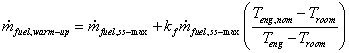
This field describes the nominal engine temperature during normal, steady-state operation, ![]() [°C].
[°C].
This field describes the value for the coefficient used to determine the rate of power production during warm up. The coefficient kp is used in the following relation,
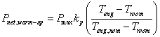
This field is used to describe a limit to the fuel flow rate during warm up. The limit is a ratio multiplied by the maximum fuel flow rate during normal operation (corresponding to the fuel flow for maximum electrical power). If the warm up operating fuel flow rate is twice the steady state fuel flow at maximum power, then a value of 2.0 would be entered in this field. This field is only used with the nominal engine temperature warm up mode and is intended for Stirling engines.
This field is used to model the warm up operation when the warm up mode is “TimeDelay.”
Enter the time between activation and power generation in seconds.
This field describes the power used by the CHP unit’s ancillary systems while in cool down operation mode. Cool down operation mode occurs whenever the unit has recently been told to stop producing power. Power here is consumed and entered as a positive value that indicates negative generation. For example, a component such as a cooling fan might continue to run during cool down.
This field is used to describe the time it takes for the CHP unit to cool off and complete the cool down operation. Enter the time between deactivation and the end of a cool down period in seconds.
This field is used to choose between two different control situations for the cool down operation. The two options for this field are “MandatoryCoolDown” and “OptionalCoolDown.” The former is used to direct the model to complete the entire cool down period before the generator can subsequently enter warm up mode. The latter directs the model to allow immediately switching to warm up mode, if power is requested before the cool down period is completed.
An example IDF showing how this object is used is provided below:
Generator:MicroCHP:NonNormalizedParameters,
SENERTECH5_5KW, !- Name
5500.0000, !- Maximum Electric Power {W}
0.0000, !- Minimum Electric Power {W}
0.0000, !- Minimum Cooling Water Flow Rate {kg/s}
80.0000, !- Maximum Cooling Water Temperature {C}
SenerTechElEff, !- Electrical Efficiency Curve Name
SenerTechThermEff, !- Thermal Efficiency Curve Name
InternalControl, !- Cooling Water Flow Rate Mode
SenerTechCoolWaterflow, !- Cooling Water Flow Rate Curve Name
SenerTechAirFlow, !- Air Flow Rate Curve Name
1000000000.0000, !- Maximum Net Electrical Power Rate of Change {W/s}
1000000000.0000, !- Maximum Fuel Flow Rate of Change {kg/s2}
741.0000, !- Heat Exchanger U-Factor Times Area Value {W/K}
13.7000, !- Skin Loss U-Factor Times Area Value {W/K}
0.5000, !- Skin Loss Radiative Fraction
63605.6000, !- Aggregated Thermal Mass of Energy Conversion Portion of Generator {W/K}
1000.7000, !- Aggregated Thermal Mass of Heat Recovery Portion of Generator {W/K}
0.0000, !- Standby Power {W}
TimeDelay, !- Warm Up Mode
, !- Warm Up Fuel Flow Rate Coefficient
, !- Nominal Engine Operating Temperature {C}
, !- Warm Up Power Coefficient
, !- Warm Up Fuel Flow Rate Limit Ratio
60.0000, !- Warm Up Delay Time {s}
0.0000, !- Cool Down Power {W}
60.0000, !- Cool Down Delay Time {s}
OptionalCoolDown; !- Restart Mode
HVAC,Sum,Generator Time in Off Mode [s]
HVAC,Sum,Generator Time in Standby Mode [s]
HVAC,Sum,Generator Time in Warm up Mode [s]
HVAC,Sum,Generator Time in Normal Operating Mode [s]
HVAC,Sum,Generator Time in Cool Down Mode [s]
HVAC,Average,Generator Electric Power Produced [W]
HVAC,Sum,Generator Electric Energy Produced [J]
HVAC,Average,Generator Electrical Efficiency [ ]
HVAC,Average,Generator Thermal Efficiency [ ]
HVAC,Average,Generator Gross Heat Input Rate to Engine [W]
HVAC,Average,Generator Steady-State Rate of Heat Generation in Engine [W]
HVAC,Average,Generator Rate of Heat Recovery [W]
HVAC,Average,Generator Air Flow Rate [kg/s]
HVAC,Average,Generator Molar Fuel Flow Rate [kmol/s]
HVAC,Average,Generator Fuel Flow Rate [kg/s]
HVAC,Average,Generator Engine Temperature [C]
HVAC,Average,Generator Coolant Inlet Temperature [C]
HVAC,Average,Generator Coolant Outlet Temperature [C]
HVAC,Sum,Generator Fuel Energy Use HHV [J]
HVAC,Average,Generator Fuel Energy Use Rate HHV [W]
HVAC,Sum,Generator Fuel Energy Use LHV [J]
HVAC,Average,Generator Fuel Energy Use Rate LHV [W]
HVAC,Average,Generator Fuel Compressor Electrical Power [W]
HVAC,Sum,Generator Fuel Compressor Electrical Energy [J]
HVAC,Average,Generator Fuel Compressor Skin Losses [W]
HVAC,Average,Generator Heat Loss Rate to Zone [W]
HVAC,Sum,Generator Heat Loss Energy to Zone [J]
HVAC,Average,Generator Convection Heat Loss Rate to Zone [W]
HVAC,Average,Generator Radiation Heat Loss Rate to Zone [W]
This report is the amount of time the generator spent in “Off” mode in seconds.
This report is the amount of time the generator spent in “Stand By” mode in seconds.
This report is the amount of time the generator spent in “Warm Up” mode in seconds.
This report is the amount of time the generator spent in “Normal Operating” mode in seconds.
This report is the amount of time the generator spent in “Cool Down” mode in seconds.
This report is the net electrical power produced by the generator in watts.
This report is the net electrical energy produced by the generator in joules. This report variable is also put on the meter for on-site production.
This is the result for electrical efficiency.
This is the result for thermal efficiency.
This is the gross rate of heat input (from fuel consumption) into the engine control volume.
This is an interim value in the dynamic thermal calculation that describes the steady-state heat generation in the engine.
These are the rate and energy of thermal heat transferred from the engine to the heat recovery fluid in the coolant control volume.
This is the rate of air flow thru the engine on a mass basis.
This is the rate of fuel flow thru the engine on a molar basis.
This is the rate of fuel flow thru the engine on a mass basis.
This is the model result for engine temperature in C. This is the lumped temperature for the engine control volume.
This is the temperature of the inlet water used for heat recovery. It is determined by the balance of plant connected to the generator.
This report is the model prediction for the leaving temperature of water used for heat recovery. If there is no flow this is the modeled prediction for the mass of cooling water in contact with the engine.
This is the energy used by the cogeneration device in terms of higher heating value in joules. This is the report variable is also put on the meter for natural gas.
This is the rate of fuel energy use by the cogeneration device in terms of higher heating value in watts.
This is the fuel energy used by the cogeneration device in terms of lower heating value in joules.
This is the rate of fuel energy use by the cogeneration device in terms of lower heating value in watts
Rate of heat gain to zone from cogeneration unit.
Heat gains to zone from cogeneration unit.
Portion of rate of heat gain to zone in the form of surface convection heat transfer.
Portion of heat gains to zone in the form of surface radiation heat transfer (to other surfaces in zone).
This object is used to model small Fuel Cell (FC) generators. IEA/ECBCS Annex 42 – see www.cogen-sim.net, developed the FC model implemented in EnergyPlus. The model can be used for two general types of fuel cells, solid oxide fuel cells (SOFC) and proton exchange membrane fuel cells (PEMFC). Warning! This is a complicated model, intended primarily for research. Because fuel cells for cogeneration (producing both heat and electricity) are not yet a mature product for building systems, the input data for this model are extremely difficult to obtain. However, the model is designed to allow investigating the relative implications of a broad array of subsystems and interactions with the building.
There should be one Generator:FuelCell object for each individual FC generator in the model. Multiple fuel cell generators can be included in a given simulation. Because there are a large number of inputs to the FC model and numerous, somewhat separable subsystems within a fuel cell, the EnergyPlus input objects have been organized into a number of separate input objects. This object simply refers to the names of all the other input objects that provide the input details for individual subsystems within the fuel cell cogeneration device. The following figure diagrams these separate subsystems. (not shown is an optional stack cooler with separate connections to heat recovery water loop and surrounding zone air).
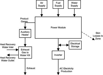
Figure 136. Fuel cell subsystems.
Note that the FC model is formulated using the Lower Heating Value (LHV) of the fuel, whereas most other parts of EnergyPlus use the Higher Heating Value (HHV). LHV has important advantages over HHV in the context of the quality of heat recovered. While model coefficients for input performance descriptions are to be based on LHV, energy consumption and tariff calculations are also reported on HHV basis when using this model.
This field contains a unique name for the fuel cell.
This field contains the name of a Generator:FuelCell:PowerModule input object.
This field contains the name of a Generator:FuelCell:AirSupply input object.
This field contains the name of a Generator:FuelSupply input object.
This field contains the name of a Generator:FuelCell:WaterSupply input object.
This field contains the name of a Generator:FuelCell:AuxiliaryHeater input object.
This field contains the name of a Generator:FuelCell:ExhaustGasToWaterHeatExchanger input object.
This field contains the name of a Generator:FuelCell:ElectricalStorage input object.
This field contains the name of a Generator:FuelCell:Inverter input object.
This field contains the name of a Generator:FuelCell:StackCooler input object. This is optional. The presence of a stack cooler distinguishes between SOFC and PEMFC with PEMFC operating at lower temperatures and requiring a separate subsystem to maintain stack temperatures.
An example input data file (IDF) entry for this object is provided below:
Generator:FuelCell,
FCT SOFC, !- Name
FCT SOFC Power Module, !- Power Module Name
FCT SOFC Air Supply, !- Air Supply Name
FCT SOFC Fuel Supply, !- Fuel Supply Name
FCT SOFC Water Supply, !- Water Supply Name
FCT SOFC Auxiliary Heater, !- Auxiliary Heater Name
FCT SOFC Exhaust HX, !- Heat Exchanger Name
FCT SOFC Battery, !- Electrical Storage Name
FCT SOFC Inverter; !- Inverter Name
The following report variables are available for the fuel cell model.
Output:Variable,*,Generator Electric Power Produced,hourly; !- HVAC Average [W]
Output:Variable,*,Generator Electric Energy Produced,hourly; !- HVAC Sum [J]
Output:Variable,*,Generator Thermal Power Produced,hourly; !- HVAC Average [W]
Output:Variable,*,Generator Thermal Energy Produced,hourly; !- HVAC Sum [J]
Output:Variable,*,Generator Fuel Consumption HHV Basis,hourly; !- HVAC Sum [J]
Output:Variable,*,Generator Fuel Consumption Rate HHV Basis,hourly; !- HVAC Average [W]
Output:Variable,*,Generator Fuel Consumption LHV Basis,hourly; !- HVAC Sum [J]
Output:Variable,*,Generator Fuel Consumption Rate LHV Basis,hourly; !- HVAC Average [W]
Output:Variable,*,FuelCell Heat Loss Rate to Zone,hourly; !- HVAC Average [W]
Output:Variable,*,FuelCell Heat Loss Energy to Zone,hourly; !- HVAC Sum [J]
Output:Variable,*,FuelCell Convection Heat Loss Rate to Zone,hourly; !- HVAC Average [W]
Output:Variable,*,FuelCell Radiation Heat Loss Rate to Zone,hourly; !- HVAC Average [W]
This report is the net electrical power produced by the generator in watts.
This report is the net electrical energy produced by the generator in joules. This report variable is also put on the meter for on-site production.
These are the rate and energy of thermal heat transferred from the engine to the heat recovery fluid in the coolant control volume.
This is the energy used by the cogeneration device in terms of higher heating value in joules. This is the report variable is also put on the meter for natural gas.
This is the rate of fuel energy use by the cogeneration device in terms of higher heating value in watts.
This is the fuel energy used by the cogeneration device in terms of lower heating value in joules.
This is the rate of fuel energy use by the cogeneration device in terms of lower heating value in watts.
This variable provides the results for the total rate of skin losses from the fuel cell to the surrounding zone.
This variable provides the results for the total energy in skin losses from the fuel cell to the surrounding zone.
This variable provides the results for the rate of skin losses in the form of surface convection heat transfer from the fuel cell to the surrounding zone.
This variable provides the results for the rate of skin losses in the form of radiation heat transfer from the fuel cell to the surrounding zone.
Using the FC model with DisplayAdvancedReportVariables (see Diagnostics object or use of operating system’s environment variables) makes the following output variables available as listed in the RDD file. There are a large number of output variables that provide access to the inner workings of the model and individual subsystems that are not likely to be useful for the average user.
HVAC,Average,FC Air Temperature at Inlet [C]
HVAC,Average,FC Air Temperature Entering Power Module [C]
HVAC,Average,FC Air Flow Rate [kmol/s]
HVAC,Average,FC Air Enthalpy Entering Power Module [W]
HVAC,Average,FC Air Blower Electrical Power [W]
HVAC,Sum,FC Air Blower Electrical Energy [J]
HVAC,Average,FC Air Blower Skin Losses [W]
HVAC,Average,FC Fuel Temperature at Inlet [C]
HVAC,Average,FC Fuel Temperature Entering Power Module [C]
HVAC,Average,FC Fuel Flow Rate [kmol/s]
HVAC,Average,FC Fuel Enthalpy Entering Power Module [W]
HVAC,Average,FC Fuel Compressor Electrical Power [W]
HVAC,Sum,FC Fuel Compressor Electrical Energy [J]
HVAC,Average,FC Fuel Compressor Skin Losses [W]
HVAC,Average,FC Reforming Water Temperature at Inlet [C]
HVAC,Average,FC Reforming Water Temperature Entering Power Module [C]
HVAC,Average,FC Reforming Water Flow Rate [kmol/sec]
HVAC,Average,FC Reforming Water Pump Electrical Power [W]
HVAC,Sum,FC Reforming Water Pump Electrical Energy [J]
HVAC,Average,FC Reforming Water Enthalpy Entering Power Module [W]
HVAC,Average,FC Product Gas Temperature [C]
HVAC,Average,FC Product Gas Enthalpy [W]
HVAC,Average,FC Product Gas Flow Rate [kmol/s]
HVAC,Average,FC Product Gas Argon Flow Rate [kmol/s]
HVAC,Average,FC Product Gas Carbon Dioxide Flow Rate [kmol/s]
HVAC,Average,FC Product Gas Water Vapor Flow Rate [kmol/s]
HVAC,Average,FC Product Gas Nitrogen Flow Rate [kmol/s]
HVAC,Average,FC Product Gas Oxygen Flow Rate [kmol/s]
HVAC,Average,FC Power Conditioning Losses [W]
HVAC,Average,FC DC Power Generated [W]
HVAC,Average,FC DC Power Efficiency [ ]
HVAC,Average,FC Electrical Storage State of Charge [J]
HVAC,Average,FC DC Power Into Storage [W]
HVAC,Sum,FC DC Energy Into Storage [J]
HVAC,Average,FC DC Power From Storage [W]
HVAC,Sum,FC DC Energy From Storage [J]
HVAC,Average,FC AC Ancillaries Power [W]
HVAC,Sum,FC AC Ancillaries Energy [J]
HVAC,Average,FC Heat Loss Rate to Zone [W]
HVAC,Sum,FC Heat Loss Energy to Zone [J]
HVAC,Average,FC Convection Heat Loss Rate to Zone [W]
HVAC,Average,FC Radiation Heat Loss Rate to Zone [W]
HVAC,Sum,FC Model Iterations [ ]
HVAC,Sum,FC Regula Falsi Iterations [ ]
This variable provides the temperature of air supplied to the FC.
This variable provides the temperature of the air supplied to the power module after it has gone through the blower and received any heat recovered from other subsystems.
This variable provides the results for ![]() , the flow rate of air into the FC.
, the flow rate of air into the FC.
This variable provides the results for ![]() , which is the enthalpy flow in the air stream entering the power module relative to 25ºC.
, which is the enthalpy flow in the air stream entering the power module relative to 25ºC.
This variable provides the results for ![]() , which is the electrical power used by the air supply blower.
, which is the electrical power used by the air supply blower.
This variable provides the results for the energy used by the air supply blower. It is also added to the appropriate meters.
This variable provides the results for ![]() , which is the rate of energy “lost” to the surroundings.
, which is the rate of energy “lost” to the surroundings.
This variable provides the temperature of the fuel supplied to the FC.
This variable provides the temperature of the fuel supplied to the power module after it has gone through the compressor.
This variable provides the results for ![]() , which is the flow rate of fuel into the FC.
, which is the flow rate of fuel into the FC.
This variable provides the results for ![]() , which is the enthalpy flow in the fuel stream entering the power module relative to 25ºC.
, which is the enthalpy flow in the fuel stream entering the power module relative to 25ºC.
This variable provides the results for ![]() , which is the electrical power used by the fuel supply compressor.
, which is the electrical power used by the fuel supply compressor.
This variable provides the results for the energy used by the fuel supply compressor. It is also added to the appropriate meters.
This variable provides the results for the rate of energy “lost” to the surroundings.
This variable provides the temperature of the water supplied to the FC for reforming.
This variable provides the temperature of the water supplied to the power module after it has gone through the pump.
This variable provides the results for ![]() , which the flow rate of reforming water into the FC.
, which the flow rate of reforming water into the FC.
This variable provides the results for ![]() , which is the electrical power used by the water pump.
, which is the electrical power used by the water pump.
This variable provides the results for energy used by the water pump. It is also added to the appropriate meters.
This variable provides the results for ![]() which is the enthalpy flow of the water stream entering the power module relative to 25ºC.
which is the enthalpy flow of the water stream entering the power module relative to 25ºC.
This variable provides the results for the temperature of the product gas stream leaving the fuel cell power module.
This variable provides the results for ![]() , which is the enthalpy flow in the product gas stream leaving the power module relative to 25ºC.
, which is the enthalpy flow in the product gas stream leaving the power module relative to 25ºC.
This variable provides the results for the flow rate of all the product gases leaving the fuel cell power module.
This variable provides the results for the flow rate of the argon gas leaving the fuel cell power module.
This variable provides the results for the flow rate of the carbon dioxide gas leaving the fuel cell power module.
This variable provides the results for the flow rate of the water gas leaving the fuel cell power module.
This variable provides the results for the flow rate of the nitrogen gas leaving the fuel cell power module.
This variable provides the results for the flow rate of the oxygen gas leaving the fuel cell power module.
This variable provides the results for the power losses associated with inefficiencies in the inverter.
This variable provides the results for ![]() , which is the net DC electrical power produced by the fuel cell power module.
, which is the net DC electrical power produced by the fuel cell power module.
This variable provides the results for ![]() , which is the electrical efficiency of the fuel cell power module.
, which is the electrical efficiency of the fuel cell power module.
This variable provides the results for state of charge of the electrical storage device inside the fuel cell. Although the units are Joules, this is a state variable and is reported as an average rather than a sum.
This variable provides the rate at which power was stored into the fuel cell’s electrical storage subsystem.
This variable provides the energy stored into the fuel cell’s electrical storage subsystem.
This variable provides the rate at which power was drawn from the fuel cell’s electrical storage subsystem.
This variable provides the energy drawn from the fuel cell’s electrical storage subsystem.
This variable provides the results for ![]() , which is the rate at which ancillary devices within the power module use electricity supplied to the fuel cell by an external source.
, which is the rate at which ancillary devices within the power module use electricity supplied to the fuel cell by an external source.
This variable provides the results for the energy used by AC ancillaries. It is also added to the appropriate meters.
This variable provides information on the numerical method used to calculate the FC model. EnergyPlus uses a sequential substitution iterative algorithm to solve the main heat balance equation for the FC model. This report variable indicates the number of iterations needed to converge.
This variable provides information on the numerical method used to calculate product gas temperature as a function of the product gas’s enthalpy. A Regula Falsi numerical method is used to invert the Shomate equation for enthalpy as a function of temperature. This report variable indicates the number of iterations needed for the Regula Falsi method to converge.
This object is used to describe the core power module subsystem of the FC. This includes the fuel cell stack, fuel reformer, and whatever ancillary devices are included inside. If the model has multiple FC generators that are of the exact same type, then only one of these objects is needed and all the Generator:FuelCell can reference it. The model uses a number of curves to describe operating performance. Input data for specific models of FC are not yet available but will be produced by IEA Annex 42 and should be available in the future.
This field contains a unique name for the fuel cell power module subsystem.
This field is used to choose between different modes of inputting the electrical efficiency curve. There are two options available for this field: “Annex42” and “Normalized”. The “Annex42” option indicates that the efficiency curves are not normalized and are used for the single size and type of FC product. The “Normalized” option indicates that the efficiency curves are normalized (as is standard practice in EnergyPlus) relative to a single rating point. In the Annex42 mode, the curves directly represent efficiency as a function of fuel use, but in the Normalized mode, the curves represent an efficiency modification that is applied to the efficiency at the rating point.
This field contains the name of a Curve:Quadratic input object described elsewhere in the input file. The curve is a function of the net DC electric power, ![]() (W), produced by the power module and describes either the electrical efficiency or the how the efficiency is modified depending on the mode selected in the previous field. This quadratic curve is just one part of the entire parametric relation used to describe electrical efficiency
(W), produced by the power module and describes either the electrical efficiency or the how the efficiency is modified depending on the mode selected in the previous field. This quadratic curve is just one part of the entire parametric relation used to describe electrical efficiency ![]() . For the Annex42 mode the full relation for efficiency is,
. For the Annex42 mode the full relation for efficiency is,
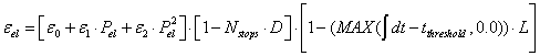
where the Curve:Quadratic input object named in this field serves to define the quadratic portion in the first set of brackets. For the Normalized mode the full relation for efficiency is,
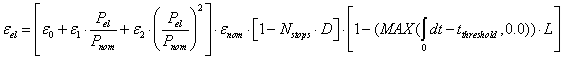
where ![]() is the nominal electrical efficiency at the rating point
is the nominal electrical efficiency at the rating point ![]() which are described in the next two fields. The Normalized mode may be more useful for a simulation study that needs to vary the capacity of the FC.
which are described in the next two fields. The Normalized mode may be more useful for a simulation study that needs to vary the capacity of the FC.
This field is used for the “Normalized” efficiency curve mode and provides the nominal efficiency ![]() (dimensionless) at the rating point. This field can be left blank if using the “Annex42” mode.
(dimensionless) at the rating point. This field can be left blank if using the “Annex42” mode.
This field is used for the “Normalized” efficiency curve mode and provides the nominal net DC electrical power produced ![]() (W) at the rating point. This field can be left blank if using the “Annex42” mode.
(W) at the rating point. This field can be left blank if using the “Annex42” mode.
This field is used to describe the number of times the FC has been cycled on and off prior to the start of the simulation. FC products might degrade as a result of starting and stopping the fuel cell stack, so the model includes terms to model the degradation effects of cycling FC units on and off. This is the initial value of the ![]() term in the efficiency relation above.
term in the efficiency relation above.
This field is used to describe the fixed value representing the fractional performance degradation associated with each start and stop cycle. This is the value of ![]() in the efficiency relations above. If there is no degradation from cycling, then D should be 0.0.
in the efficiency relations above. If there is no degradation from cycling, then D should be 0.0.
This field is used to describe the amount of time the FC has been operating prior to the start of the simulation. FC products might degrade over time so the model includes terms to model the degradation effects of FC run time. This is the initial value of the integrated run time term ![]() .
.
This field is used to describe the fixed value representing the fractional performance degradation associated with the total amount of run time. This is the value of ![]() in the efficiency relations above. If there is no degradation from run time, the L should be 0.0.
in the efficiency relations above. If there is no degradation from run time, the L should be 0.0.
This field is used to describe the time period for which there is no degradation associated with the amount of run time. This provides the ability to model a system that initially operates without degradation for some period time before it starts to degrade. This is the value of ![]() in the efficiency relations above.
in the efficiency relations above.
This field is used to describe the maximum allowable rate at which the fuel cell can increase the level of power it produces (W/s). This is a time derivative of the net DC electrical power used to limit how fast the FC can ramp up.
This field is used to describe the maximum allowable rate at which the fuel cell can decrease the level of power it produces (W/s). This is a time derivative of the net DC electrical power used to limit how fast the FC can ramp down.
This field is used to describe the length of time (seconds) of the start up period when the FC is turned on.
This field is used to describe the amount of fuel (kmol) used during the entire start up period. The fuel is the same type as what is described in the Generator:FuelSupply object elsewhere in the input file.
This field is used to describe the amount of electricity (Joules) used by ancillary equipment during the entire start up period.
This field is used to describe the amount of electricity (Joules) produced by the power module during the entire start up period.
This field is used to describe the length of time (seconds) of the shut down period.
This field is used to describe the amount of fuel (kmol) used during the entire shut down period. The fuel is the same type as what is described in the Generator:FuelSupply object elsewhere in the input file.
This field is used to describe the amount of electricity (J) used by ancillary equipment during the entire shut down period.
This field is used to describe the constant term, ![]() , in a relation that describes the AC electrical power used by ancillary equipment located inside the power module,
, in a relation that describes the AC electrical power used by ancillary equipment located inside the power module, ![]() . The model uses this relation,
. The model uses this relation,
![]()
where ![]() is the rate of fuel use in the power module (kmol/s).
is the rate of fuel use in the power module (kmol/s).
This field is used to describe the linear term, ![]() , in the relation shown in the previous field.
, in the relation shown in the previous field.
This field is used to select the mode for how skin losses are modeled. Skin losses are heat energy “lost” from the power module and transferred to the surrounding thermal zone named in the following field. There are three alpha options to choose from: “ConstantRate”, “UAForProcessGasTemperature”, or “QuadraticFunctionOfFuelRate.” Enter ConstantRate in this field to model skin losses using a constant rate, e.g. 100 watts. Enter UAForProcessGasTemperature to model skin losses using a “UA-Delta-T” calculation method with the temperature difference determined by the power module’s product gas temperature and the surrounding zone. Enter QuadraticFunctionOfFuelRate to model skin losses as a function of the rate of fuel use.
This field is used to describe the thermal zone that will receive skin and other heat losses from the FC. This should be the name of a Zone input object declared elsewhere in the input file.
This field is used to describe the portion of skin losses that are in the form of thermal radiation. This controls the radiative/convective split for the energy transferred to the zone by the FC.
This field is used to describe the constant rate of skin losses (W). This field is used with the ConstantRate mode. It can be left blank for other skin loss modes.
This field is used to describe the “UA” term (W/K). This field is used with the UAForProcessGasTemperature mode. It can be left blank for other skin loss modes. “UA” is the product of the overall heat transfer coefficient “U” and the area “A.”
This field is used to refer to the name of a quadratic curve object defined elsewhere in the input file. The quadratic curve should define skin heat loss rate as a function of the fuel use rate (kmol/s) so that,
![]()
This field is used to describe the rate of dilution air (kmol/sec) drawn into, or through, the power module. This air stream may not be present in all FC products. It is used for limiting skin and stack heat losses and for strategies that mitigate potential safety issue were fuel gases to escape the stack.
This field is used to describe the rate at which the fuel cell stack adds energy to the dilution air stream. It is entered as a constant heat rate (W).
This field is used to describe the air node where the dilution air is drawn from. This would typically be the name of the air node associated with the thermal zone where the FC is located.
This field is used to describe the air node where the dilution air is exhausted to. This could be the inlets to a heat recovery ventilator or an exhaust node.
This field is used to describe the minimum operating point for the net DC electric power, ![]() (W).
(W).
This field is used to describe the maximum operating point for the net DC electric power, ![]() (W).
(W).
An example input data file (IDF) entry for this object is provided below:
Generator:FuelCell:PowerModule,
FCT SOFC Power Module, !- Name
Annex42, !- Efficiency Curve Mode
FCT Power Curve, !- Efficiency Curve Name
0.354, !- Nominal Efficiency
3400, !- Nominal Electrical Power {W}
0, !- Number of Stops at Start of Simulation
0.0, !- Cycling Performance Degradation Coefficient
0, !- Number of Run Hours at Beginning of Simulation {hr}
0.0, !- Accumulated Run Time Degradation Coefficient
10000, !- Run Time Degradation Initiation Time Threshold {hr}
1.4, !- Power Up Transient Limit {W/s}
0.2, !- Power Down Transient Limit {W/s}
0.0, !- Start Up Time {s}
0.2, !- Start Up Fuel {kmol}
, !- Start Up Electricity Consumption {J}
0.0, !- Start Up Electricity Produced {J}
0.0, !- Shut Down Time {s}
0.2, !- Shut Down Fuel {kmol}
, !- Shut Down Electricity Consumption {J}
0.0, !- Ancilliary Electricity Constant Term
0.0, !- Ancilliary Electricity Linear Term
ConstantRate, !- Skin Loss Calculation Mode
ZN_1_FLR_1_SEC_5, !- Zone Name
0.6392, !- Skin Loss Radiative Fraction
729, !- Constant Skin Loss Rate {W}
0.0, !- Skin Loss U-Factor Times Area Term {W/K}
, !- Skin Loss Quadratic Curve Name
6.156E-3, !- Dilution Air Flow Rate {kmol/s}
2307, !- Stack Heat loss to Dilution Air {W}
SOFC Air HR Inlet, !- Dilution Inlet Air Node Name
SOFC Air HR Outlet, !- Dilution Outlet Air Node Name
3010, !- Minimum Operating Point {W}
3728; !- Maximum Operating Point {W}
This object is optional and is used to define details needed to model the stack cooler on PEMFC.
This field contains a unique name for the PEM fuel cell stack cooler
This field contains the node name for the water inlet to the stack cooler.
This field contains the node name for the water outlet from the stack cooler.
This field contains the nominal stack operating temperature for the PEMFC, ![]() . This field and the next five provide values for use in the empirical equation for the rate of heat extracted from the fuel cell power module by the stack cooler using the following relation
. This field and the next five provide values for use in the empirical equation for the rate of heat extracted from the fuel cell power module by the stack cooler using the following relation
![]()
This field contains the actual stack operating temperature for the PEMFC, ![]() .
.
This field contains the coefficient r0 in the equation above.
This field contains the coefficient r1 in the equation above.
This field contains the coefficient r2 in the equation above.
This field contains the coefficient r3 in the equation above.
The stack cooler is assumed to have a closed water circulation loop that is used to extract heat from the stack and move it to a cogeneration heat exchanger and/or an air cooler. This field is used to enter the flow rate of coolant in this loop.
This is the heat transfer coefficient between the stack and the coolant.
This field provides the value for an adjustment factor, ![]() , used in the following relation for the cogeneration heat transfer coefficient,
, used in the following relation for the cogeneration heat transfer coefficient, ![]() :
:
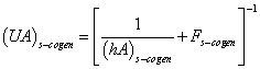
This field provides the value for the cogeneration heat exchanger area, ![]()
This field provides the value for ![]() in the following relation for the cogeneration heat exchanger convection coefficient,
in the following relation for the cogeneration heat exchanger convection coefficient, ![]() :
:

This field provides the value for ![]() in the relation above for the cogeneration heat exchanger convection coefficient,
in the relation above for the cogeneration heat exchanger convection coefficient, ![]() .
.
This field provides the value for ![]() is the relation above for the cogeneration heat exchanger convection coefficient,
is the relation above for the cogeneration heat exchanger convection coefficient, ![]() .
.
This field is the power used by the stack cooler’s circulating pump in Watts. It is a constant power draw whenever the stack cooler is active.
This field is the fraction of the pump power consumption that is lost to the surround zone.
This field and the next two are used to define coefficients for the following relation for the power used by the air-cooler’s fan to dump excess heat into the surrounding zone:
![]()
This field provides a value for the coefficient f1 in the relation above.
This field provides a value for the coefficient f2 in the relation above.
This object is used to define details of the air supply subsystem.
This field contains a unique name for the fuel cell air supply subsystem.
This field is used to define the air node where the inlet air stream is drawn from. If the FC uses outdoor air then the node named here should be designated an outdoor air node. If the FC draws air from its surroundings, then this would be the name of the air node associated with the thermal zone containing the FC.
This field contains the name of a Curve:Cubic input object described elsewhere in the input file. The curve provides the power used by the air blower (W) as a cubic function of the rate of air supply (kmol/s).
![]()
This field describes the portion of blower electrical power that is “lost” to the surroundings. The rest of the energy is added to the air stream. A heat loss factor of 1.0 indicates that all the heat is lost to the surroundings and no energy is added to the air inlet stream.
This field describes how the model will calculate the air supply rate. There are three options to choose from: “AirRatiobyStoics”, “QuadraticFunctionofElectricPower”, and “QuadraticFunctionofFuelRate.” The choice will determine how the model calculates the rate of air and will depend on the formulations used to develop model input data. The choices are described in the next four fields.
This field describes the excess air ratio beyond stoichiometric air supply. This field is only used if the air supply rate calculation mode is AirRatiobyStoics. The total air supply ratio will be the value entered here plus 1.0. Thus if 1.0 is entered in this field, the total air flow will be 2.0 times what is needed to exactly match stoichiometry with the fuel supply.
This field contains the name of a QuadraticCurve input object described elsewhere in the input file. This field is only used if the air supply rate calculation mode is QuadraticFunctionofElectricPower. The quadratic curve named here describes the first part of the relation below used to calculate the rate of inlet air, ![]() (kmol/s). It is a quadratic function of the net DC electrical power,
(kmol/s). It is a quadratic function of the net DC electrical power, ![]() (W).
(W).
![]()
![]()
This field is used to describe the air temperature coefficient, ![]() , used to adjust inlet air flow rate in the relations for inlet air rate.
, used to adjust inlet air flow rate in the relations for inlet air rate.
This field contains the name of a Curve:Quadratic input object described elsewhere in the input file. This field is only used if the air supply rate calculation mode is QuadraticFunctionofFuelRate. The quadratic curve named here describes the first part of the relation used to calculate the rate of inlet air, ![]() (kmol/s). It is a quadratic function of the fuel flow rate,
(kmol/s). It is a quadratic function of the fuel flow rate, ![]() .
.
![]()
![]()
This field is used to control how heat losses from three other subsystems within the FC may or may not be recovered by the air inlet. There are six possible choices for what to use in this field: “NoRecovery” “RecoverBurnerInverterStorage” “RecoverAuxiliaryBurner” “RecoverInverterandStorage” “RecoverInverter” and “RecoverElectricalStorage”. If heat is recovered then that means that energy “losses” from those subsystems are added to the inlet air and fed back into the FC power module. The following table clarifies the meaning of the six possible choices.
Table 32. Air Intake Heat Recovery Mode Choices
|
Field Choice |
Inverter Heat Losses Recovered? |
Electrical Storage Heat Losses Recovered? |
Auxiliary Heater Losses Recovered? |
|
NoRecovery” |
No |
No |
No |
|
RecoverBurnerInverterStorage |
Yes |
Yes |
Yes |
|
RecoverAuxiliaryBurner |
No |
No |
Yes |
|
RecoverInverterandStorage |
Yes |
Yes |
No |
|
RecoverInverter |
Yes |
No |
No |
|
RecoverElectricalStorage |
No |
Yes |
No |
This field is used to choose between two different modes for describing the make up of the inlet air stream. There are two possible choices: “AmbientAir” or “UserDefinedConstituents.” Choosing the AmbientAir mode will automatically set the composition of air to be usual at: 77.28% nitrogen, 20.73% oxygen, 1.04% water, 0.92% argon, and 0.03% carbon dioxide. Choosing UserDefinedConstituents allows the user to customize the make up the inlet air in the remaining fields.
This field is used to describe the number of constituents in the inlet air. This field is only used if the air supply constituent mode is set to UserDefinedConstituents. The maximum number is 5.
The remaining fields in this object are repeating pairs of fields with one pair for each constituent and the same number as described in the previous field. The pairs consist of the name of the constituent followed by the molar fraction of that constituent.
These fields describe the air stream constituents by name. The name field for each pair must be filled with one of these choices: “CarbonDioxide”, “Nitrogen,” “Oxygen,” “Water,” or “Argon.”
These fields describe the molar fraction of the air stream constituents. It is very important that the sum of the molar fractions add up to 1.0.
An example input data file (IDF) entry for this object is provided below:
Generator:FuelCell:AirSupply,
FCT SOFC Air Supply, !- Name
SOFC Air Inlet Node, !- Air Inlet Node Name
FCT Blower Power Curve, !- Blower Power Curve Name
1.0, !- Blower Heat Loss Factor
QuadraticFunctionofElectricPower, !- Air Supply Rate Calculation Mode
, !- Stoichiometric Ratio
FCT Excess Air Ratio Curve, !- Air Rate Function of Electric Power Curve Name
2.83507E-3, !- Air Rate Air Temperature Coefficient
, !- Air Rate Function of Fuel Rate Curve Name
NoRecovery, !- Air Intake Heat Recovery Mode
UserDefinedConstituents, !- Air Supply Constituent Mode
5, !- Number of UserDefined Constituents
Nitrogen, !- Constituent 1 Name
0.7728, !- Molar Fraction 1
Oxygen, !- Constituent 2 Name
0.2073, !- Molar Fraction 2
Water, !- Constituent 3 Name
0.0104, !- Molar Fraction 3
Argon, !- Constituent 4 Name
0.0092, !- Molar Fraction 4
CarbonDioxide, !- Constituent 5 Name
0.0003; !- Molar Fraction 5
This object is used to provide details of the water supply subsystem. This water is used for steam reforming of the fuel and is not the same as the water used for thermal heat recovery.
Generator:FuelCell:WaterSupply,
A1, \field Name
\required-field
\reference FCWaterSupNames
A2, \field Reformer Water Flow Rate Function of Fuel Rate Curve Name
\type object-list
\object-list QuadraticCurves
A3, \field Reformer Water Pump Power Function of Fuel Rate Curve Name
\type object-list
\object-list QubicCurves
N1, \field Pump Heat Loss Factor
A4, \field Water Temperature Modeling Mode
\type choice
\key TemperatureFromAirNode
\key TemperatureFromWaterNode
\key TemperatureFromSchedule
\key MainsWaterTemperature
A5, \field Water Temperature Reference Node Name
A6; \field Water Temperature Schedule Name
\type object-list
\object-list ScheduleNames
This field contains a unique name for the fuel cell water supply subsystem.
This field contains the name of a Curve:Quadratic input object described elsewhere in the input file. The curve provides the rate of water flow (kmol/sec) as a function of fuel flow rate (kmol/sec).
![]()
If the unit does not use water for reforming then use a “null” quadratic where all the coefficients are 0.0.
This field contains the name of a Curve:Cubic input object described elsewhere in the input file. The curve provides the power used by the water pump (W) as a cubic function of the rate of water supply (kmol/s).
![]()
If the unit does not use water for reforming then use a “null” cubic where all the coefficients are 0.0.
This field describes the portion of pump electrical power that is “lost” to the surroundings. The rest of the energy is added to the water stream. A heat loss factor of 1.0 indicates that all the heat is lost to the surroundings and no energy is added to the water inlet stream.
This field describes how the model will determine the inlet temperature of the water stream. There are four options to choose from: “TemperatureFromAirNode,” “TemperatureFromWaterNode,” “TemperatureFromSchedule,” and “MainsWaterTemperature.” For the first two options, the temperature of the water inlet is determined by the temperature at the node named in the next field. For the third option, the temperature is determined by the schedule in the last field. Using the MainsWaterTemperature option requires also defining a separate “Site:WaterMainsTemperature” input object elsewhere in the input file.
This field is used to define the node where the temperature of the inlet water stream is obtained. This can be either an air node or a water node.
This field is used to define the name of a schedule, defined elsewhere in the input file, that will be used to determine the temperature of the water inlet stream when using the TemperatureFromSchedule mode.
An example input data file (IDF) entry for this object is provided below:
Generator:FuelCell:WaterSupply,
FCT SOFC Water Supply, !- Name
Null Quadratic, !- Reformer Water Flow Rate Function of Fuel Rate Curve Name
Null Cubic, !- Reformer Water Pump Power Function of Fuel Rate Curve Name
0.0, !- Pump Heat Loss Factor
TemperatureFromAirNode, !- Water Temperature Modeling Mode
SOFC Air Inlet Node, !- Water Temperature Reference Node Name
; !- Water Temperature Schedule Name
Curve:Quadratic,
Null Quadratic, !- Name
0.0, !- Coefficient1 Constant
0.0, !- Coefficient2 x
0.0, !- Coefficient3 x**2
-1.0E+10, !- Minimum Value of x
1.0E+10; !- Maximum Value of x
Curve:Cubic,
Null Cubic, !- Name
0.0, !- Coefficient1 Constant
0.0, !- Coefficient2 x
0.0, !- Coefficient3 x**2
0.0, !- Coefficient4 x**3
-1.0E+10, !- Minimum Value of x
1.0E+10; !- Maximum Value of x
This object is intended for modeling an auxiliary heater, however this portion of the model is not yet available in EnergyPlus. An auxiliary heater may be present in fuel cell products so that the unit can meet much higher thermal loads than would be possible using only cogeneration. This portion of the model will be added in the future once suitable cogeneration control capabilities are also available. The input fields are described for future reference but may change. The program still requires one of these objects be included even though the data are not yet used (so that internal data structures can be allocated).
This field contains a unique name for the fuel cell auxiliary heater subsystem.
This field describes the excess air ratio beyond stoichiometric air supply for the heater. The total air supply ratio will be the value entered here plus 1.0. Thus if 1.0 is entered in this field, the total air flow will be 2.0 times what is needed to exactly match stoichiometry with the fuel supply.
This field describes the constant term, ![]() , used to model the auxiliary burner’s ancillary devices such as fans and ignition controls. The electrical power for ancillaries is calculated using,
, used to model the auxiliary burner’s ancillary devices such as fans and ignition controls. The electrical power for ancillaries is calculated using,
![]()
This field describes the linear term, ![]() , used to model the auxiliary burner’s ancillary devices.
, used to model the auxiliary burner’s ancillary devices.
This field describes the “UA” term (W/K) for calculating skin losses in the auxiliary burner. “UA” is the product of the overall heat transfer coefficient “U” and the area “A.” The skin heat losses are calculated using,
![]()
where, ![]() is temperature of product gases leaving the auxiliary burner and includes the mixing of the product gases from the fuel cell power module. Thus, the input for UA should reflect this choice of reference temperature rather than an exterior surface temperature of the auxiliary burner.
is temperature of product gases leaving the auxiliary burner and includes the mixing of the product gases from the fuel cell power module. Thus, the input for UA should reflect this choice of reference temperature rather than an exterior surface temperature of the auxiliary burner.
This field describes the user’s choice for what happens to the skin losses. There are two options: “SurroundingZone” and “AirInletForFuelCell”. Entering SurroundingZone will direct the model to put the “lost” energy into the surrounding thermal Zone named in the next field. Entering AirInletForFuelCell will direct the model to put the “lost” energy into the air inlet stream for the fuel cell to preheat that air.
This field is used to determine the zone that will receive the skin losses. Enter the name of a Zone declared elsewhere in the input file. This field is only used if the “SurroundingZone” mode is used in the previous field.
This field describes the user’s choice for how the capacity of the auxiliary heater will be defined. There are two options: “Watts” or “kmol/s.” Entering Watts will direct the program to use the next two fields to determine the maximum and minimum heating capacity. Entering kmol/s will direct the program to use the last two fields to determine the maximum and minimum heating capacities.
This field is used to describe the maximum heating capacity of the auxiliary burner (W).
This field is used to describe the minimum heating capacity of the auxiliary burner (W).
This field is used to describe the maximum fuel use rate for the auxiliary burner (kmol/s).
This field is used to describe the minimum fuel use rate for the auxiliary burner (kmol/s).
An example input data file (IDF) entry for this object is provided below:
Generator:FuelCell:AuxiliaryHeater,
FCT SOFC Auxiliary Heater, !- Name
0.0, !- Excess Air Ratio
0.0, !- Ancilliary Power Constant Term
0.0, !- Ancilliary Power Linear Term
0.5, !- Skin Loss U-Factor Times Area Value
SurroundingZone, !- Skin Loss Destination
ZN_1_FLR_1_SEC_5, !- Zone Name to Receive Skin Losses
Watts, !- Heating Capacity Units
0.0, !- Maximum Heating Capacity in Watts
0.0, !- Minimum Heating Capacity in Watts
, !- Maximum Heating Capacity in Kmol per Second
; !- Minimum Heating Capacity in Kmol per Second
Generator:FuelCell:ExhaustGasToWaterHeatExchanger
This object is used to describe the exhaust gas heat exchanger subsystem of the FC used to recovery thermal energy.
This field contains a unique name for the fuel cell power module subsystem.
This field contains the name of the node that connects the heat exchanger’s inlet to the plant loop. This water is used for heat recovery.
This field contains the name of the node that connects the heat exchanger’s outlet to the plant loop.
This field describes the design maximum flow rate of the heat recovery water (m3/s). The value should match the design flow rate of the plant loop connected to the FC.
This field is used to determine which node will receive the exhaust air stream leaving the FC. This node will usually be outside and not be referenced elsewhere. However, if the exhaust stream is used in a heat recovery ventilator (as described in section 11 of the Annex 42 specification) then the node would be reference in the heat recovery ventilator object.
This field is used to direct how EnergyPlus will calculate heat exchanger performance. The Annex 42 model provides for four different methods of modeling the heat exchanger. The choices available for this field are: “FixedEffectiveness” (method 1 in Annex 42 specification), “EmpiricalUAeff ” (method 2), “FundementalUAeff ” (method 3), or “Condensing” (method 4). The remaining fields provide input data for the different methods. The heat exchanger correlations are described below.
This field describes constant heat exchanger effectiveness, ![]() . This field is only used with the “FixedEffectiveness” mode, which corresponds to “method 1” in the Annex 42 specification. For this mode, the heat exchange between the exhaust gases and the heat recovery water are calculated using,
. This field is only used with the “FixedEffectiveness” mode, which corresponds to “method 1” in the Annex 42 specification. For this mode, the heat exchange between the exhaust gases and the heat recovery water are calculated using,
![]()
where, ![]() is the minimum value of
is the minimum value of ![]() and
and ![]() .
.
This field describes the value of ![]() in the relation below for effective UA. This field is used with the “EmpiricalUAeff” mode, which corresponds to “method 2” in the Annex 42 specification and with the “Condensing” mode, which corresponds to “method 4”. This method uses the log mean temperature difference (LMTD) approach to calculate the heat exchange:
in the relation below for effective UA. This field is used with the “EmpiricalUAeff” mode, which corresponds to “method 2” in the Annex 42 specification and with the “Condensing” mode, which corresponds to “method 4”. This method uses the log mean temperature difference (LMTD) approach to calculate the heat exchange:
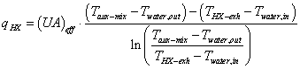
The user input in this field, and the next four fields, describe coefficients in an empirical relation for ![]() :
:
![]()
This field describes the value of ![]() in the relation above for effective UA. This field is used with the “EmpiricalUAeff” mode, which corresponds to “method 2” in the Annex 42 specification and with the “Condensing” mode, which corresponds to “method 4”.
in the relation above for effective UA. This field is used with the “EmpiricalUAeff” mode, which corresponds to “method 2” in the Annex 42 specification and with the “Condensing” mode, which corresponds to “method 4”.
This field describes the value of ![]() in the relation below. This field is only used with the “FundementalUAeff” mode, which corresponds to “method 3” in the Annex 42 specification. For this mode, the heat exchange is calculated using the LMTD method, but the effective UA is determined using:
in the relation below. This field is only used with the “FundementalUAeff” mode, which corresponds to “method 3” in the Annex 42 specification. For this mode, the heat exchange is calculated using the LMTD method, but the effective UA is determined using:
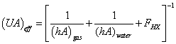
where,
![]() is an adjustment factor,
is an adjustment factor,
 ,
,

This field describes the value of ![]() in the relation above. This field is only used with the “FundementalUAeff” mode, which corresponds to “method 3” in the Annex 42 specification.
in the relation above. This field is only used with the “FundementalUAeff” mode, which corresponds to “method 3” in the Annex 42 specification.
This field describes the value of ![]() in the relation below for the rate of condensation of water from the gas stream,
in the relation below for the rate of condensation of water from the gas stream, ![]() . This field is only used with the “Condensing” mode, which corresponds to “method 4” in the Annex 42 specification. This method uses a modified version of the LMTD approach to calculate heat exchange:
. This field is only used with the “Condensing” mode, which corresponds to “method 4” in the Annex 42 specification. This method uses a modified version of the LMTD approach to calculate heat exchange:
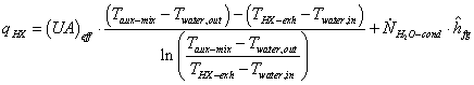
where,
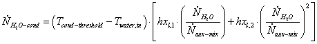
This field describes the value of ![]() in the relation above for the rate of condensation of water from the gas stream,
in the relation above for the rate of condensation of water from the gas stream, ![]() . This field is only used with the “Condensing” mode, which corresponds to “method 4” in the Annex 42 specification.
. This field is only used with the “Condensing” mode, which corresponds to “method 4” in the Annex 42 specification.
An example input data file (IDF) entry for this object is provided below:
Generator:FuelCell:ExhaustGasToWaterHeatExchanger,
FCT SOFC Exhaust HX, !- Name
Small SOFC Heat Rec Inlet Node, !- Heat Recovery Water Inlet Node Name
Small SOFC Heat Rec Outlet Node, !- Heat Recovery Water Outlet Node Name
0.0004, !- Heat Recovery Water Maximum Flow Rate {m3/s}
SOFC Air Outlet Node, !- Exhaust Outlet Air Node Name
CONDENSING, !- Heat Exchanger Calculation Method
, !- Method 1 Heat Exchanger Effectiveness
83.1, !- Method 2 Parameter hxs0
4798, !- Method 2 Parameter hxs1
-138E+3, !- Method 2 Parameter hxs2
-353.8E+3, !- Method 2 Parameter hxs3
5.15E+8, !- Method 2 Parameter hxs4
, !- Method 3 h0Gas Coefficient
, !- Method 3 NdotGasRef Coefficient
, !- Method 3 n Coefficient
, !- Method 3 Gas Area
, !- Method 3 h0 Water Coefficient
, !- Method 3 N dot Water ref Coefficient
, !- Method 3 m Coefficient
, !- Method 3 Area Water Coefficient
, !- Method 3 F Adjustment Factor
-1.96E-4, !- Method 4 hxl1 Coefficient
3.1E-3, !- Method 4 hxl2 Coefficient
35.0; !- Method 4 Condensation Threshold {C}
This object is used to describe the electrical storage subsystem for the FC. The electrical storage model is a very simple “constrained bucket” model. Future developments made add additional models for battery systems. Note that this electrical storage is embedded within the FC device.
This field contains a unique name for the fuel cell electrical storage subsystem.
This field is used to direct how EnergyPlus will model electrical storage. The only choice currently available is “SimpleEfficiencyWithConstraints,” which should be entered in this field. Future developments may expand the number of models available for electrical storage.
This field describes the value of ![]() in the relation for the State of Charge,
in the relation for the State of Charge, ![]() :
:
![]()
This is the energetic efficiency of charging the storage device. A value of 1.0 means that the storage device does not lose any energy when charging. Note that the model can recover the “lost” energy into the air supply intake.
This field describes the value of ![]() in the relation for the State of Charge,
in the relation for the State of Charge, ![]() :
:
![]()
This is the energetic efficiency of discharging the storage device. A value of 1.0 means that the storage device does not lose any energy when discharging. Note that the model can recover the “lost” energy into the air supply intake.
This field describes the maximum amount of electrical energy that can be stored in the device (J).
This field describes the maximum rate at which electrical power can be discharged from the storage device (W).
This field describes the maximum rate at which electrical power can charge the storage device (W).
This field describes the value for the initial state of charge (J). This allows the storage device to contain some amount of stored electricity at the beginning of the simulation period.
An example input data file (IDF) entry for this object is provided below:
Generator:FuelCell:ElectricalStorage,
FCT SOFC Battery, !- Name
SimpleEfficiencyWithConstraints, !- Choice of Model
1.0, !- Nominal Charging Energetic Efficiency
1.0, !- Nominal Discharging Energetic Efficiency
0, !- Simple Maximum Capacity {J}
0, !- Simple Maximum Power Draw {W}
0, !- Simple Maximum Power Store {W}
0; !- Initial Charge State {J}
This object is used to describe the power condition unit subsystem of the FC. This object models an inverter system contained within a fuel cell system that converts from direct current (DC) to alternating current (AC).
This field contains a unique name for the fuel cell inverter subsystem.
This field is used to direct how EnergyPlus will calculate the inverter efficiency. There are two possible choices: “Constant” or “Quadratic”.
This field describes the value for inverter efficiency when using the Constant mode.
This field names a Curve:Quadratic object defined elsewhere in the input file. The curve determines inverter efficiency as a function of the DC power entering the inverter as follows:
![]()
An example input data file (IDF) entry for this object is provided below:
Generator:FuelCell:Inverter,
FCT SOFC Inverter, !- Name
Quadratic, !- Inverter Efficiency Calculation Mode
, !- Inverter Efficiency
FCT Inverter Quadratic; !- Efficiency Function of DC Power Curve Name
Curve:Quadratic,
FCT Inverter Quadratic, !- Name
0.560717, !- Coefficient1 Constant
1.24019E-4, !- Coefficient2 x
-2.01648E-8, !- Coefficient3 x**2
-1.0E+10, !- Minimum Value of x
1.0E+10; !- Maximum Value of x
This object is used to define details of the fuel supply for certain generators. This object allows the user to describe a wide array of possible fuel mixtures. The program contains data and internal methods to calculate the properties of the various mixtures of gaseous fuels. The program will calculate the Lower Heating Value (LHV), Higher Heating Value (HHV), and molecular weight for the fuel mixture. The fuel properties are then use by both fuel cell and Micro CHP models. Results of the gas phase thermochemistry modeling are also reported in the EIO file.
In addition to gaseous mixtures, the Micro CHP model is able to use generic liquid fuels and this object is used to describe the properties.
Note that the fuel consumption metering is currently handled by the Natural Gas meter. So no matter what fuel mixture is defined in this object, the aggregated reports from EnergyPlus meters for (natural) Gas will include the fuel used for the generator (with the Joule content based on HHV).
This field contains a unique name for the fuel cell fuel supply subsystem.
This field describes how the model will determine the temperature of the fuel. There are two options for this field to choose from: “TemperatureFromAirNode” and “Scheduled.” If this field contains TemperatureFromAirNode then the fuel is modeled as having the same temperature as the air node that is named in the next field. If this field contains Scheduled then the fuel is modeled as having the temperature described in a schedule defined elsewhere in the input file.
This field contains the name of the air node used to obtain the inlet temperature of the fuel. This field is only used if the Fuel Temperature Modeling Mode is set to TemperatureFromAirNode.
This field contains the name of a temperature schedule defined elsewhere in the input file. This field is only used if the Fuel Temperature Modeling Mode is set to Scheduled. The temperature of the fuel inlet will be obtained from the schedule.
This field contains the name of a Curve:Cubic input object described elsewhere in the input file. The curve provides the electrical power used by the fuel compressor (W) as a cubic function of the rate of fuel supply (kmol/s).
![]()
This field describes the portion of the compressor electrical power that is “lost” to the surroundings. The rest of the energy is added to the fuel stream. A heat loss factor of 1.0 indicates that all the heat is lost to the surroundings and no energy is added to the fuel inlet stream.
Choose between “GaseousConstituents” or “LiquidGeneric”.
For fuel type “LiquidGeneric,” this field is used to enter the lower heating value of the fuel in units of kJ/kg.
For fuel type “LiquidGeneric,” this field is used to enter the higher heating value of the fuel in units of kJ/kg.
For fuel type “LiquidGeneric,” this field is used to enter the molecular weight of the fuel in units of g/mol.
This field is not used. This part of the Annex 42 model was not implemented in EnergyPlus; see the FuelFactors object.
This field is used to describe the number of constituents in the inlet fuel supply. The maximum number of different types of constituents is currently set to 12.
The remaining fields in this object are repeating pairs of fields with one pair for each constituent and the same number as described in the previous field. The field set pairs consist of the name of the constituent followed by the molar fraction of that constituent.
These fields describe the fuel stream constituents by name. The name field for each pair must be filled with one of these 14 choices: “CarbonDioxide”, “Nitrogen”, “Oxygen”, “Water”, “Argon”, “Hydrogen”, “Methane”, “Ethane”, “Propane”, “Butane”, “Pentane”, “Hexane”, “Methanol”, and “Ethanol”. No other fuel constituents can currently be modeled. The properties of the constituents are already contained inside the program as provided in the Annex 42 model specification.
These fields describe the molar fraction of the fuel stream constituents. It is very important that the sum of the molar fractions add up to 1.0.
In addition to the following report variables, the resulting fuel heating values are also reported to the eio file.
HVAC,Average,FuelCell Fuel Compressor Electrical Power [W]
HVAC,Sum,FuelCell Fuel Compressor Electrical Energy [J]
HVAC,Average,FuelCell Fuel Compressor Skin Losses [W]
This is the rate of energy use by the gas compressor, if any, that provides fuel at a higher pressure.
This is the energy used by the gas compressor, if any, that provides fuel at a higher pressure.
Convective heat gains to zone from gas compressor, if any, that provides fuel at a higher pressure.
EnergyPlus offers different options for predicting the electricity produced by solar electric photovoltaic (PV) panels. The three different options are “Simple”, “Equivalent One-Diode” and “Sandia” and the choice will determine the mathematical models used to determine energy production. The first allows the user to input an arbitrary efficiency. The other two models use empirical relationships to predict PV operating performance based on many environmental variables such as cell temperature. The PV models can be used with either normal PV modules or as part of a hybrid photovoltaic/thermal (PVT) flat plat collector.
The generator is connected to an Electric Load Center. The PV models refer to surface input objects defined elsewhere in the input file. This object describes an array that is “attached” to a surface object in order to describe its orientation and to access results of the solar insolation calculations. These can be either Heat Transfer or Shading objects (see Surfaces). This will define the orientation of the solar panel for the detailed models and also the area for the simple model. The exposure of that surface to incident solar radiation is calculated using the full set of models in EnergyPlus that are used to account for solar thermal loads arising from building windows and walls. Therefore the incident solar radiation is calculated to include the effects of shading and reflections from other surfaces declared in the input file. In addition to the output variables associated with PV models, there are numerous related output variables available for the surfaces including: 'Surface Ext Sunlit Area', 'Surface Ext Sunlit Fraction', 'Surface Ext Solar Incident', 'Surface Ext Solar Beam Incident', 'Surface Ext Solar Sky Diffuse Incident', 'Surface Ext Solar Ground Diffuse Incident', 'Surface Ext Solar Beam Cosine Of Incidence Angle', 'Surface Ext Solar From Sky Diffuse Refl From Ground', 'Surface Ext Solar From Sky Diffuse Refl From Obstructions', 'Surface Ext Beam Sol From Bm-To-Bm Refl From Obstructions', 'Surface Ext Diff Sol From Bm-To-Diff Refl From Obstructions', and 'Surface Ext Solar From Bm-To-Diff Refl From Ground.’ Note that it is possible to define a PV array area that doesn’t conform to the surface area (i.e. model a PV array area that is larger or smaller than what is available on the surface) so it is the users responsibility to not over-specify area when determining how many modules will fit onto a surface. However this type of input is allowed.
EnergyPlus does not include models for ancillary equipment for a PV array including charge controllers or power-point trackers. The operation of the entire electrical system that must go along with a PV array is not currently modeled in EnergyPlus and is therefore assumed to operate in ideal ways. The PV production models do not resolve voltage and current, only power (and energy). Electricity production is metered based on the output of the inverter. Output results are available before and after the inverter. One assumption is that the array is assumed to be always operating at the maximum power point. Energy production is based on the assumption that the quasi-steady power prediction is constant and continuous over the simulation timestep.
For a variety of reasons, actual installations of photovoltaics are often observed to exhibit system-level problems that significantly reduce electricity production. Therefore this modeling should be considered a method of bracketing the upper end of electricity production rather than an accurate prediction of what the panels will produce. Also note that the model predictions are closely related to the solar radiation data (typically of of TMY2 origin) in the EnergyPlus weather file, that the solar data in these is usually from a model rather than direct measurements, and that solar resources encountered by a real installation in a given year are likely to differ from the weather data file.
This object is used to describe an array of PV modules and how they are to be modeled. A series of different PV arrays can be connected to a single electric load center (and inverter) by listing them all in an ElectricLoadCenter:Generator object.
This field is a unique name for the PV array.
This field is the name of a surface that defines the location and geometry of the array.
This field is the type of PV performance model. The choices are the class names for the three modeling options:
PhotovoltaicPerformance:Simple
PhotovoltaicPerformance:EquivalentOne-Diode
PhotovoltaicPerformance:Sandia.
This is the name of the PV performance object define elsewhere (corresponding to the object type listed in the previous field)
The PV model allows for different ways of integrating with other EnergyPlus heat transfer surfaces and models and calculating cell temperature. For Building Integrated PV (BIPV), the “Integrated” options allow for the PV modeling to be coupled to the surface heat transfer models elsewhere in EnergyPlus. The user must select one of these options for this field:
· Decoupled. The cell temperature of modules in the array is computed based on a energy balance relative to NOCT conditions. The input fields for Module Heat Capacity and Module Heat Loss Coefficient are ignored.
· DecoupledUllebergDynamic the cell temperature is calculated based on a dynamic model developed by Ulleberg[13]. The input fields for Module Heat Capacity and Module Heat Loss Coefficient are required.
· IntegratedSurfaceOutsideFace The cell temperature is obtained from the outside face of the Surface:Heat Transfer named in the previous field. Energy exported by the module is removed from the heat transfer surface (at the position determined by the associated Construction with Internal Source). The input fields for Module Heat Capacity and Module Heat Loss Coefficient are ignored.
· IntegratedTranspiredCollector The cell temperature is obtained from the collector surface temperature in the unglazed transpired collector model. Energy exported by the module is removed from the collector surface. The input fields for Module Heat Capacity and Module Heat Loss Coefficient are ignored.
· IntegratedExteriorVentedCavity The cell temperature is obtained from the exterior baffle temperature in the naturally ventilated exterior cavity model. Energy exported by the module is removed from the exterior baffle surface. The input fields for Module Heat Capacity and Module Heat Loss Coefficient are ignored.
· PhotovoltaicThermalSolarCollector The cell temperature is obtained from the photovoltaic/thermal solar collector model. If the PV layer is inside the collector, then the incident solar is modified by the photovoltaic/thermal solar collector model.
This field is the number of modules wired in parallel to form the PV array.
This field is the number of modules wired in series to form the PV array.
Using the Generator:PV:Simple object makes a number of output variables available.
This output variable is the power of DC electricity delivered.
This output variable is the energy in DC electricity.
This output variable is the resulting efficiency .
The two more detailed PV models also have the following output variables.
This output variable represents the temperature of the solar cell used in the calculation of cell performance.
This output variable represents the short circuit current of the PV array. This is provided to describe the I-V characteristics.
This output variable represents the open circuit voltage of the PV array. This is provided to describe the I-V characteristics.
The PhotovoltaicPerformance:Simple object describes a simple model of photovoltaics that may be useful for early phase design analysis. In this model the user has direct access to the efficiency with which surfaces convert incident solar radiation to electricity and need not specify arrays of specific modules. The full geometric model for solar radiation is used, including shading and reflections, to determine the incident solar resource. This model is intended to be useful for design purposes to quickly get an idea of the levels for annual production and peak power. The model can also accept arbitrary conversion efficiencies and does not require actual production units be tested to obtain performance coefficients.
This field is the name of the PV array. The name is only used as an identifier. Multiple instances need have unique names.
This field is the user defined fraction for the area of surface named in the parent PV object that will have active PV cells on it. The area actually covered with solar cells will be the net area of the surface (gross area less any subsurfaces like windows) times the fraction entered here. This fraction includes the difference between PV module area and active cells within it and any losses for how closely packed modules can be arranged on surface. The value should be between 0.0 and 1.0.
This field specifies how the PV array efficiency values are input. There are two choices, Fixed and Scheduled. If this field is set to ‘Fixed’ then the PV array always has the efficiency value specified in the next field. If this field is set to ‘Scheduled’ then the efficiency is determined by a user defined schedule named in the second field to follow.
This field specifies the efficiency with which solar incident energy is converted to electricity. Efficiency = (electrical power generated [W])/(power of incident solar[W]). These efficiency values are dimensionless and should be between 0.0 and 1.0.
This field should be set to the name of schedule defined elsewhere in the input file. This schedule should specify dimensionless efficiency values between 0.0 and 1.0. This could be used for example to vary the efficiency to match results computed with more detailed models.
An example idf instance of this object follows:
PhotovoltaicPerformance:Simple,
Simple PV Flat, !- Name
0.1044 , !- Fraction of Surface area that has active solar cells
FIXED , !- Conversion efficiency input mode
0.12 , !- Value for cell efficiency if fixed
; !- Name of Schedule that Defines Efficiency
This object describes the performance characteristics of Photovoltaic (PV) modules to be modeled using an equivalent one-diode circuit. This model is also known at the 4- or 5-parameter TRNSYS model for photovoltaics.
The following table shows several sample PV array types with their input values.
Table 33. Photovoltaics Array Types with Values
|
|
Short Circuit Current |
Open Circuit Voltage |
Voltage at Maximum Power |
Current at Maximum Power |
Temperature Coefficient of Short Circuit Current |
Temperature Coefficient of Open Circuit Voltage |
Number of Cells in Series per Module |
Cell Temperature at NOCT Conditions |
Module Area |
|
Units: |
[A] |
[V] |
[V] |
[A] |
{A/K] |
[V/K] |
[-] |
[K] |
[m2] |
|
ASE |
6.2 |
60 |
50.5 |
5.6 |
0.001 |
-0.0038 |
216 |
318 |
2.43 |
|
BPsolar 275 |
4.75 |
21.4 |
17 |
4.45 |
0.00065 |
-0.08 |
36 |
320 |
0.63 |
|
BPsolar 3160 |
4.8 |
44.2 |
35.1 |
4.55 |
0.00065 |
-0.16 |
72 |
320 |
1.26 |
|
BPsolar 380 |
4.8 |
22.1 |
17.6 |
4.55 |
0.00065 |
-0.08 |
36 |
320 |
0.65 |
|
BPsolar 4160 |
4.9 |
44.2 |
35.4 |
4.52 |
0.00065 |
-0.16 |
72 |
320 |
1.26 |
|
BPsolar 5170 |
5 |
44.2 |
36 |
4.72 |
0.00065 |
-0.16 |
72 |
320 |
1.26 |
|
BPsolar 585 |
5 |
22.1 |
18 |
4.72 |
0.00065 |
-0.08 |
36 |
320 |
0.65 |
|
Shell |
6.9 |
21.7 |
17.5 |
6.3 |
0.0028 |
-0.076 |
36 |
318 |
0.86856 |
|
Shell |
3.45 |
43.5 |
35 |
3.15 |
0.0014 |
-0.152 |
72 |
318 |
0.86856 |
|
Shell SP70 |
4.7 |
21.4 |
16.5 |
4.25 |
0.002 |
-0.076 |
36 |
318 |
0.6324 |
|
Shell SP75 |
4.8 |
21.7 |
17 |
4.4 |
0.002 |
-0.076 |
36 |
318 |
0.6324 |
|
Shell SP140 |
4.7 |
42.8 |
33 |
4.25 |
0.002 |
-0.152 |
72 |
318 |
1.320308 |
|
Shell SP150 |
4.8 |
43.4 |
34 |
4.4 |
0.002 |
-0.152 |
72 |
318 |
1.320308 |
|
Shell S70 |
4.5 |
21.2 |
17 |
4 |
0.002 |
-0.076 |
36 |
317 |
0.7076 |
|
Shell S75 |
4.7 |
21.6 |
17.6 |
4.2 |
0.002 |
-0.076 |
36 |
317 |
0.7076 |
|
Shell S105 |
4.5 |
31.8 |
25.5 |
3.9 |
0.002 |
-0.115 |
54 |
317 |
1.037 |
|
Shell S115 |
4.7 |
32.8 |
26.8 |
4.2 |
0.002 |
-0.115 |
54 |
317 |
1.037 |
|
Shell ST40 |
2.68 |
23.3 |
16.6 |
2.41 |
0.00035 |
-0.1 |
16 |
320 |
0.424104 |
|
UniSolar |
4.8 |
23.8 |
16.5 |
3.88 |
0.00065 |
-0.1 |
40 |
323 |
0.65 |
|
UniSolar |
4.8 |
47.6 |
33 |
3.88 |
0.00065 |
-0.2 |
80 |
323 |
1.25 |
Where:
Shunt Resistance: the value of shunt resistance is finite only if the PV Module being modeled is a thin film variety. For all crystaline silicon modules the value is essentially infinite
Shunt Resistance value: 1,000,000 W (ohms)
Module Heat Loss Coefficient: this value is dependent more on the array configuration than on the module itself.
Module Heat Loss Coefficient value: 30 W/m2-K
Module Heat Capacity: this is a typical value for a silicon based sandwich construction framed PV panel.
Module Heat Capacity Value: 50,000 J/m2-K
Reference Temperature: 298K (25C)
Insolation at Reference Conditions: 1000 W/m2
Ambient Temperature at NOCT conditions: 293K (20C)
Insolation at NOCT Conditions: 800 W/m2
Average tau-alpha Product: .9
Semiconductor Bandgap: 1.12 eV
This field contains the uniqe name for the photovoltaic module performance data. The name is only used as an identifier.
This field is used to describe the type of technology used in the PV module. There are two options available, CrystallineSilicon and AmorphousSilicon. The choice affects the modeling.
This field is an integer representing the number of individual cells wired in series to make up a single module. The typical number for a 12V crystalline silicon PV module is 36.
This field is the active area of the PV module in m2.
This field indicates the transmittance-absorptance product at normal incidence angles for the PV modules. If the ta product is positive, that value will be used for all angles of incidence. If the value specified is negative, then the magnitude of the given value will be used for normal incidence and the IAM modifier correlation will be used for all other angles.
This field is the semiconductor bandgap for the PV material. The bandgap for silicon is 1.12 eV (electron volts).
This field is the shunt (parallel) resistance (in W) in the single diode electrical model of the PV. The shunt resistance is effectively infinite for crystalline silicon based PV modules and is finite for thin film and exotic metal modules.
This field is the short circuit current (in Amps) for an individual module in the PV array at reference conditions.
This field is the open circuit voltage (in Volts) for an individual module in the PV array at reference conditions.
This field is the ambient temperature (in Kelvin) at reference conditions. The value is usually 298K
This field is the radiation level (in W/m2) at reference conditions. The value is usually 1000 W/m2.
This field is module current (in Amps) at the maximum power point and reference conditions.
This field is module voltage (in Volts) at the maximum power point and reference conditions.
This field accounts for the fact that the module short circuit current is temperature dependent. The coefficient is given in Amps/Kelvin.
This field accounts for the fact that the module open circuit voltage is temperature dependent. The coefficient is given in Volts/Kelvin.
This field is the ambient temperature (in Kelvin) from the Nominal Operating Cell Temperature (NOCT) test. The value is usually 293 K
This field is the cell temperature (in Kelvin) from the Nominal Operating Cell Temperature (NOCT) test.
This field is the insolation level (in W/m2) from the Nominal Operating Cell Temperature (NOCT) test. The value is usually 800 W/m2.
This field is the heat loss coefficient (in W/m2.K) for the array. The heat loss coefficient is dependent upon measures taken to actively or passively promote airflow over the array surface. The heat loss coefficient value is used only if the Integration and Cell Temperature Mode is set to “Decoupled Ulleberg Dynamic.”
This field is the heat capacity (in J/m2.K) of the modules in the array. It describes the module’s ability to store incident solar radiation internally. Such energy storage is manifested as a temperature increase in the modules that is considered to be undesirable. The total heat capacity value is used only if the Integration and Cell Temperature Mode is set to “Decoupled Ulleberg Dynamic.”
An IDF example:
PhotovoltaicPerformance:EquivalentOne-Diode,
Siemens, ! Name
CrystallineSilicon, !cell Type
36, !cells in series [-]
1.0, !module area [m2]
0.9, !tau alpha product at normal incidence [-]
1.12, !electron bandgap [eV]
1000000, !shunt resistance [ohms]
6.5, !short circuit current at reference conditions [A/K]
21.6, !open circuit voltage at reference conditions [V/K]
25, !temperature at reference conditions [C]
1000, !radiation at reference conditions [W/m2]
5.9, !current at max power
17, !voltage at max power
0.002, !temperature coefficient of short circuit current
-0.079, !temperature coefficient of open circuit voltage
20, !ambient temperature at NOCT [C]
45, !cell temperature at NOCT [C]
800, !radiation at NOCT [W/m2]
30, !heat loss coefficient [W/m2.K]
50000; !total heat capacity (only used in TC mode 1)
This ‘PhotovoltaicPerformance:Sandia’ object describes the performance of a single type of module. The model used with this object for predicting the electricity generated by photovoltaics is referred to as the Sandia model. This model is based on work done at Sandia National Lab, Albuquerque, NM by David King -- with the help of many others.
This object describes performance input data needed for specific makes and models of production PV panels using the empirical coefficients assembled by Sandia National Laboratory. There are a large number of empirical coefficients required to use the Sandia model. These data are obtained after extensive measurements and data reduction. This testing has been performed for some types of production panels and Sandia publishes a database of module and array performance parameters on the web at www.sandia.gov/pv. The entries in the database as of January 15, 2004 were converted to idf segments and are included with the EnergyPlus release in the library file SandiaPVData.imf. There are more than hundred different module types included in the library and identified by the manufacturer’s model names listed at the beginning of the file SandiaPVData.imf. This data library file is arranged for use with EpMacro but the user can also copy .idf segments directly from the macro data set.
The Sandia model itself can aggregate multiple PV modules. Therefore, an instance of a ‘PhotovoltaicPerformance:Sandia’ object could actually represent an array of modules as well as the more usual single module. These can be can be thought of as simple larger modules and used by Generator:PV:Sandia objects in the usual manner.
The many empirical coefficients for the model are listed below and are described in more more detail in the EnergyPlus engineering documentation EngineeringDoc.pdf.
The field descriptions below focus on providing the parameter’s variable name as identified in the Sandia database. See the the EngineeringDoc.pdf for details on how the input fields are used in the correlations. The user generally would not need to worry about the details of the fields since he/she is not likely to generate the data on their own.
This field provides a unique name for the PV module. This is often the manufacturer’s identifier for a particular model of a PV module.
Units m2 , real number, area of active solar electric cell for the entire module.
“Series_Cells” in Sandia Database.
“Parallel_Cells” in Sandia Database
“Isco” in Sandia Database. Short-circuit current is a basic parameter Typically supplied by manufacturers at Standard Report Conditions. (Amps)
“Voco” in Sandia Database, Open-circuit voltage is a basic parameter typically provided by manufacturers a t Standard Report Conditions. (Volts)
“Impo” in Sandia Database. Current at maximum powerpoint is a basic parameter provided by manufacturers at Standard Report Conditions. (Amps)
“Vmpo” in Sandia Database. Voltage at maximum powerpoint is a a basic parameter typically provided by manufacturers a t Standard Report Conditions. (Volts)
“aIsc in Sandia Database” (1/degC)
“aImp” in Sandia Database (1/degC)
“C0” in Sandia Database, (non-dimensional)
“C1” in Sandia Database (non-dimensional)
“Bvoco” in Sandia Database (Volts/degC)
“mBVoc” in Sandia Database (Volts/degC)
“Bvmpo” in Sandia Database (Volts/degC)
“mBVmp” in Sandia Database (Volts/degC)
“n” in Sandia Database (non-dimensional)
“C2” in Sandia Database (non-dimensional)
“C3” in Sandia Database (non-dimensional)
“A0” in Sandia Database (non-dimensional)
“A1” in Sandia Database (non-dimensional)
“A2” in Sandia Database (non-dimensional)
“A3” in Sandia Database (non-dimensional)
“A4” in Sandia Database (non-dimensional)
“B0” in Sandia Database (non-dimensional)
“B1” in Sandia Database (non-dimensional)
“B2” in Sandia Database (non-dimensional)
“B3” in Sandia Database (non-dimensional)
“B4” in Sandia Database (non-dimensional)
“B5” in Sandia Database (non-dimensional)
“d(Tc)” in Sandia Database (deg C)
“fd” in Sandia Database (non-dimensional)
“a” in Sandia Database (non-dimensional)
“b” in Sandia Database (non-dimensional)
“C4” in Sandia Database (non-dimensional)
“C5” in Sandia Database (non-dimensional)
“Ix0” in Sandia Database (Amps)
“Ixx0” in Sandia Database (Amps)
“C6” in Sandia Database (non-dimensional)
“C7” in Sandia Database (non-dimensional)
An example of the object follows:
PhotovoltaicPerformance:Sandia,
ASE-50-ATF-17_45, ! Module Name (production Name)
0.43, ! field Active Area Acoll {m2}, single module
36, ! NcellSer {unitless}
1, ! NparSerCells
2.90, ! Isc0 {Amps}
20.70, ! Voc0 {Volts}
2.65, ! Imp0 {Amps}
17.00, ! Vmp0 {Volts}
7.8e-04, ! aIsc {1/degC}
1.0e-04, ! aImp {1/degC}
0.99, ! C0 {unitless}
3.0e-03, ! C1 {unitless}
-0.07, ! BVoc0 {Volts/degC}
0.00, ! mBVoc {Volts/degC}
-0.07, ! BVmp0 {Volts/degC}
0.00, ! mBVmp {Volts/degC}
1.29, ! Diode Factor (n) {Unitless}
0.20, ! C2 {Unitless}
-8.60, ! C3 {Unitless}
0.93, ! A0 {Unitless}
0.05, ! A1 {Unitless}
-7.9402e-03, ! A2 {Unitless}
5.2228e-04, ! A3 {Unitless}
-1.3142e-05, ! A4 {Unitless}
1.00, ! B0 {Unitless}
-2.438e-03, ! B1 {Unitless}
3.103e-04, ! B2 {Unitless}
-1.246e-05, ! B3 {Unitless}
2.112e-07, ! B4 {Unitless}
-1.359e-09, ! B5 {Unitless}
3.00, ! dT0 {degC}
1.00, ! fd {Unitless}
-3.47, ! a {Unitless}
-0.05, ! b {Unitless}
0.98, ! C4 {Unitless}
0.01, ! C5 {Unitless}
2.86, ! Ix0 {Amps}
1.85, ! Ixx0 {Amps}
1.13, ! C6 {Unitless}
-0.13, ! C7 {Unitless}
-1.359e-09, ! B5 {Unitless}
3.00, ! dT0 {degC}
1.00; ! fd {Unitless}
When using EpMacro with an typical installation of EnergyPlus, the above entry can be included in an input file by adding the following two lines to an input macro file (*.imf).
##include C:\EnergyPlus\MacroDataSets\SandiaPVdata.imf
ASE-50-ATF-17_45[]
A wind turbine is a component that converts the kinetic energy of the surrounding airstream into electricity. This model is intended to calculate the electrical power that a wind turbine system produces. The performance of wind turbine systems is dependent on the local environmental conditions such as wind speed and density of air at the height of the systems. An analysis of these conditions is necessary to accurately estimate power output. The model obtains the weather information from the weather data file in EnergyPlus and then determines the wind speed and air density at the specific height of the system. It also requires the user to input the annual average wind speed measured at the local site and the height of the measurement so that it factors in differences between the weather file wind data and the local wind data.
The model employs the general kinetic energy equation to calculate the performance characteristics of the horizontal axis wind turbine (HAWT) systems. It provides a simple approximation algorithm when the power coefficient, Cp, is available which represents the efficiency of the wind turbine in the wind power extraction from the ambient air stream. It also allows the user to input experimental constants so that the power coefficient can precisely be determined according to the characteristic of the airfoil of the system. As for the vertical axis wind turbine (VAWT) systems, it employs the general mathematical equations for straight-bladed Darrieus-type VAWT systems, which are common to VAWT systems. Various types of VAWT systems such as the Savonius-type and the curved-blade (or Egg-beater) type may be simulated with this same model.
It includes two different types of dynamic power control: FixedSpeedFixedPitch (FSFP) and VariableSpeedFixedPitch (VSFP). Currently, it does not include an algorithm for modeling pitch control such as FixedSpeedVariablePitch (FSVP) and VariableSpeedVariablePitch (VSVP). If the control type of the wind turbine is either FSVP or VSVP, the control type of VSFP will be assumed. In addition, constant power generation is assumed when the ambient wind speed is between the rated wind speed and the cut out wind speed, if the user specifies one of the last three options. The model also has the ability to account for transient losses associate with the power produced during dynamic control by a user-specified fraction.
The model does not include detailed algorithms for generators and inverters due to concerns for computational convergence, time, and usability. Instead, all conversion losses of these subsystems are included by applying a user-supplied total system efficiency to the maximum power extraction of the wind turbine. The field of the total system efficiency must be specified by the user.
A unique user assigned name for a particular wind turbine system. Any reference to this unit by another object will use this name.
The name of the schedule (ref: Schedule) that denotes whether the wind turbine system can run during a given hour. A schedule value greater than 0 (usually 1 is used) indicates that the unit can be on during the hour. A value less than or equal to 0 (usually 0 is used) denotes that the unit is off and will not operate for the hour.
This field is the type of axis of the wind turbine. The user specifies either a horizontal axis wind turbine or a vertical axis wind turbine. Each type of wind turbine employs a different algorithm for the calculation of the electrical power output of the wind turbine. The default value is HorizontalAxisWindTurbine.
This field is the type of rotor control for the wind turbine. This protects the system against the overloading for a system with no speed or pitch control and also to maximize the energy yield for the system. Four different control types are classified in the literature: FixedSpeedFixedPitch (FSFP), FixedSpeedVariablePitch (FSVP), VariableSpeedFixedPitch (VSFP), and VariableSpeedVariablePitch (VSVP). Currently, FSFP and VSFP types can be modeled in EnergyPlus. The other two types will be modeled as VSFP. If the first FSFP control type is chosen, the model assumes the maximum power at a fixed rotor speed when the power output predicted is greater than the maximum until the rotor speed reaches the maximum wind speed (see next field). If one of the last three control options is chosen, the model assumes that the system produces a constant power at the rated wind speed when the wind speed is between the rated wind speed and cut-out wind speed. The default value is VariableSpeedFixedPitch (VSFP).
This field is the maximum rotational speed of the rotor at the rated power of the wind turbine in rev/min (revolution per minute). It is used to determine the tip speed ratio of the rotor and relative flow velocity incident on a single blade of the VAWT systems.
This field is the diameter of the rotor in meters. Note that this field is not the height of the blade, but the diameter of the perpendicular circle from the vertical pole in the VAWT systems. It determines the swept area of the rotor of the HAWT systems and the chordal velocity of the VAWT systems.
This field is the height of the hub of the HAWT system, or of the pole of the VAWT system in meters. It is necessary to estimate local air density and the wind speed at this particular height where the wind turbine system is installed.
This field is the number of blades of the wind turbine. The azimuth angle of the rotor of the VAWT system is determined by dividing 360 degree by this field so that the model determines the chordal velocity component and the normal velocity component of the system. The default value is 3.
This field is the nominal power output of the wind turbine system at the rated wind speed in Watts. Note that the user should input the maximum power of the system with no control, i.e., FSFP control type, can physically produce. Manufacturers’ data also indicates it as “peak power” or “rated capacity”. If the local wind speed is greater than the rated wind speed, the model assumes constant power output of this field.
This field is the wind speed that the wind turbine system indicates the peak in the power curve in m/s. The system produces the maximum power at this speed and the speed of the rotor is managed based on this wind speed.
This field is the lowest wind speed where the wind turbine system can be operated in m/s. No power generation is achieved as long as the ambient wind speed is lower than this speed.
This field is the greatest wind speed in m/s. When the wind speed exceeds this value, the wind turbine system needs to be stopped because of inefficiencies in the system. All systems that have either pitch or speed control must be stopped when the ambient wind speed exceeds this speed. Note that the user should input a wind speed above which physical damage to the system might be caused in the case of a FSFP system. It appears as “extreme/survival/design wind speed” in the literature. The system will be turned off when the ambient wind speed is over this speed.
This field is the overall system efficiency of the wind turbine system. It includes all the conversion losses as well as transient losses during the dynamic control when the ambient wind speed is between the rated wind speed and cut-out wind speed (see previous fields). The user also has the ability to specify delivery losses from the system to the local area. If the user does not enter a fraction, the model assumes the default value of 0.835. Note that the fraction must be between zero and one.
This field is the maximum tip speed ratio between the rotor velocity and ambient wind velocity. The rotor speed varies with this ratio to maximize the power output when the rotor control types are variable speed ones. This field allows the user to adjust the power output from the particular system or to find the optimal tip speed ratio of the system. Optimal tip speed ratio is dependent on the number of blades. It is typically about 6, 5, and 3 for two-bladed, three-bladed, and four-bladed rotor, respectively. For the vertical axis wind turbine, it is smaller than horizontal axis wind turbine, and varies with the chord area. The default and maximum values are 5.0 and 12.0.
This field is the maximum fraction of power extraction from ambient wind. If the user inputs this field, the simple approximation model is assumed. The model simply employs the value of this field into the general kinetic energy equation, so that the power output is obtained. The user can obtain this field with a simple calculation from the power curve published in almost all manufacturers' specifications by using the kinetic energy equation as:
![]()
where
P = power production at the rated wind speed [W]
ρ = density of air [kg/m3]
A = swept area of rotor [m2]
V = rated wind speed [m/s]
Cp = power coefficient
The maximum and default values are 0.59 and 0.35.
This field is the local annual average wind speed that represents a representative wind profile at the location of the system in m/s. It is used to factor the difference in wind speed between the weather file wind data and the locally measured wind data so that the model minimizes uncertainties caused by improper wind data at the particular location. Considerable differences between the weather file wind data and the local wind data typically appear. The user thus needs to enter this field in order to obtain accurate local wind data. The model internally determines a multiplier and it is multiplied by the weather file wind data adjusted at the height of the system. If this field is not entered, then the model will use the wind speed from the design day or weather file information with only adjustment at the height of the rotor.
This field is the height that the local wind speed is measured in meters. The annual average wind speed (see previous field) input by the user is internally recalculated by existing EnergyPlus functions at the height of the local station. This modified wind speed is then factored and applied to the weather file wind data. If the annual local average wind speed is not entered, this field is then assumed as zero. The minimum and default values are zero and 50 meters.
This field is the blade chord area of a single blade of VAWT system in m2. It is necessary to determine the net tangential and normal forces of a single blade.
This field is the blade drag coefficient for a specific blade. It is for determining the tangential and normal force coefficients with the blade lift coefficient (see next field) so that the model can calculate the power output from the system. The user should be able to obtain this parameter for a specific blade from the manufacturers’ data. This field is only valid for VAWT systems.
This field is the blade lift coefficient for a specific blade. It is for determining the tangential and normal force coefficients with the blade drag coefficient (see previous field) so that the model can calculate the power output from the system. The user should also be able to obtain it for a specific blade from the manufacturers’ data. This field is only valid for VAWT systems.
These six fields are the parameters for the power coefficient equation shown below. These fields are used to determine the power coefficient of the system. The analytical approximation model of the power coefficient in EnergyPlus is:
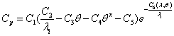
with
![]()
where
Cp = power coefficient
C1- 6 = empirical power coefficient parameters
λ = tip speed ratio (often known as TSR)
λi = tip speed ratio at ith time step
θ = azimuth angle of the pitch, 0 [degree]
If the user does not input any field of these parameters, the simple approximation model for the power coefficient will be used (see previous maximum power coefficient field). That is, the analytical approximation model of the power coefficient will be chosen only if the user inputs all these six parameters. The user also has the ability to modify each parameter when the specific value of the system is available. The default values are given in the table below.
|
C1 |
C2 |
C3 |
C4 |
C5 |
C6 |
|
0.5176 |
116 |
0.4 |
0.0 |
5.0 |
21 |
These fields are only valid for HAWT systems.
An example input for the wind turbine is shown in below.
Generator:WindTurbine,
WT1, ! Name
WT Schedule, ! Available schedule
HorizontalAxisWindTurbine, ! Rotor type
FixedSpeedVariablePitch, ! Power control type
41, ! Maximum rotational speed of the rotor {rev/min}
19.2, ! Diameter of the rotor {m}
30.5, ! Overall height of the system {m}
3, ! Number of blades
55000, ! Rated power output at the rated wind speed {W}
11, ! Rated wind speed {m/s}
3.5, ! Cut In wind speed {m/s}
25, ! Cut Out wind speed {m/s}
0.835, ! Overall wind turbine system efficiency
8, ! Maximum tip speed ratio
0.4, ! Maximum power coefficient
6.4, ! Annual local wind speed {m/s}
50, ! Height of local meteorological station {m}
, ! Blade chord area {m2}
, ! Blade drag coefficient
, ! Blade lift coefficient
0.5176, ! Power Coefficient C1
116, ! Power Coefficient C2
0.4, ! Power Coefficient C3
0, ! Power Coefficient C4
5, ! Power Coefficient C5
21; ! Power Coefficient C6
HVAC,Average, Wind Turbine Electric Power Produced [W]
HVAC,Sum, Wind Turbine Electric Energy Produced [J]
HVAC,Average, Wind Turbine Ambient Wind Speed [m/s]
HVAC,Average, Wind Turbine Ambient Air Density [kg/m3]
HVAC,Average, Wind Turbine Power Coefficient
HVAC,Average, Wind Turbine Tip Speed Ratio
HVAC,Average, Wind Turbine Chordal Velocity Component [m/s]
HVAC,Average, Wind Turbine Normal Velocity Component [m/s]
HVAC,Average, Wind Turbine Relative Flow Velocity [m/s]
HVAC,Average, Wind Turbine Angle of Attack [degree]
This report is the electric power that the wind turbine system produces.
This report is the electric energy that the wind turbine system produces.
This report is the local wind speed at the specific height of the wind turbine.
This report is the local density of the air at the specific height of the wind turbine.
This report is the ratio between the rotational speed of the tip of the blades and the ambient wind speed at the height of the hub or pole of the wind turbine.
This report represents the efficiency of the power extraction from the ambient wind of the wind turbine. It is function of the tip speed ratio and pitch angle. It is only valid for HAWT systems.
This report is the axial velocity component along the chord of the wind turbine system. It is only valid for VAWT systems.
This report is the axial velocity component of the rotor of the wind turbine system. It is only valid for VAWT systems.
This report is the local relative flow velocity that represents actual direction and velocity incident on the blades. It is the square root of the sum of both chordal velocity component and normal velocity component. It is only valid for VAWT systems.
This report is the azimuth angle between the relative flow velocity and the plane of chord. It varies as the wind speed increases, so that the lift and drag forces change.
This group of objects is used to describe the water systems in the building. EnergyPlus offers water modeling capabilities than include not only hot water systems but also the overall water systems including cold water uses, on-site water collection (e.g., from rain, condensate, or well), and storage. HVAC components may consume or collect a significant portion of the water making it appropriate to include water modeling in EnergyPlus.
All water systems are collected into an end use category called “Water Systems”. This category includes hot and cold water. Water consumed by an HVAC component will be assigned to the end use category for that component. End use subcategories are available to separate hot water from cold water if desired. Simple hot water systems can be configured as stand-alone or use a PlantLoop. The Water Systems can be connected to PlantLoops for modeling heated water end uses. However PlantLoops are not used to model cold water and the WaterUse:Storages portions of the water system. Cold water systems are connected together using WaterUse:Storage objects. WaterUse:Connections are used at the zone level to connect to both cold and hot water.
In addition to the input objects described in this section below, there are a variety of HVAC components that can be configured to interact with the water systems. These component input objects include optional fields that allow describing how the water systems are connected to them by providing the name of a storage tank. The following table lists EnergyPlus input objects that include provisions for connecting to the water systems but are described elsewhere in this document:
Table 34. Water Systems Objects
|
Input Object Name |
Type of Water Interactions |
|
Site:Precipitation |
Describes rainfall for WaterUse:RainCollector |
|
Coil:Cooling:Water |
Condensate collection to WaterUse:Storage |
|
Coil:Cooling:Water:DetailedGeometry |
Condensate collection to WaterUse:Storage |
|
Coil:Cooling:DX:SingleSpeed |
Optional evaporative condenser can be supplied by WaterUse:Storage Condensate collection to WaterUse:Storage |
|
Coil:Cooling:DX:TwoSpeed |
Evaporative condenser supplied by WaterUse:Storage Condensate collection to WaterUse:Storage |
|
Coil:Cooling:DX:TwoStageWithHumidityControlMode |
Evaporative condenser supplied by WaterUse:Storage Condensate collection to WaterUse:Storage |
|
Coil:Cooling:DX:MultiSpeed |
Evaporative condenser supplied by WaterUse:Storage Condensate collection to WaterUse:Storage |
|
Humidifier:Steam:Electric |
Water supplied by WaterUse:Storage |
|
CoolingTower:SingleSpeed |
Water supplied by WaterUse:Storage |
|
CoolingTower:TwoSpeed |
Water supplied by WaterUse:Storage |
|
CoolingTower:VariableSpeed |
Water supplied by WaterUse:Storage |
|
ZoneCoolTower:Shower |
Water supplied by WaterUse:Storage |
|
Refrigeration:CompressorRack |
Water supplied by WaterUse:Storage |
|
Refrigeration:Condenser:EvaporativeCooled |
Water supplied by WaterUse:Storage |
|
EvaporativeCooler:Direct:CelDekPad |
Evaporation water supplied by WaterUse:Storage |
|
EvaporativeCooler:Indirect:CelDekPad |
Evaporation water supplied by WaterUse:Storage |
|
EvaporativeCooler:Indirect:WetCoil |
Evaporation water supplied by WaterUse:Storage |
|
EvaporativeCooler:Indirect:ResearchSpecial |
Evaporation water supplied by WaterUse:Storage |
The WaterUse:Equipment object is a generalized object for simulating all water end uses. Hot and cold water uses are included, as well as controlled mixing of hot and cold water at the tap. The WaterUse:Equipment object can be used stand-alone, or coupled into a plant loop using the WaterUse:Connections object (see below). The WaterUse:Connections object allows water uses to be linked to WaterUse:Storage objects to store and draw reclaimed water. The WaterUse:Connections object can also simulate drainwater heat recovery.
The WaterUse:Equipment object serves all of the same purposes as the existing objects: Exterior:WaterEquipment, and HotWaterEquipment.
The WaterUse:Equipment object does a better job of modeling domestic hot water by allowing mixing at the tap in order to account for both hot and cold water used at sinks, showers, etc. It also improves on the stand-alone energy modeling of domestic hot water. Because all of the temperatures and flow rates can be solved, the energy usage can be accounted for as "Purchased Heating".
In either stand-alone mode or used with the WaterUse:Connections object, the WaterUse:Equipment object will attempt to meet a scheduled target temperature at the tap by mixing hot and cold water flows. If the hot water flow is not hot enough, or if the flow is limited by plant loop constraints, the result is a cooler mixed water temperature and the target temperature will not be met. In stand-alone mode the hot and cold water temperatures are specified by schedules. However, if the cold water schedule is omitted, the water temperature will be calculated by the Site:WaterMainsTemperature object. If the hot water schedule or target temperature schedule are omitted, all water is delivered as cold water. If only using cold water, the WaterUse:Equipment object is similar to the Exterior:WaterEquipment object.
The WaterUse:Equipment object improves on the internal gains object HotWaterEquipment by associating actual water usage with a sensible and latent gain to a zone. Equipment, such as showers, that generate a significant heat gain can be modeled using the Sensible Fraction Schedule and Latent Fraction Schedule fields. The schedules are used to set the fraction of the maximum possible heat gain (based on inlet water conditions and ambient zone conditions) that should be added to the zone. The split between sensible and latent will vary depending on the type of equipment that is to be modeled. Typically, both fractions should be small numbers.
The unique object name for reference by other objects.
Allows you to specify a user-defined end-use subcategory, e.g., "Laundry", "Dish Washing", etc. A new meter for reporting is created for each unique subcategory (ref: Report Meter). Subcategories are also reported in the ABUPS table under the "Water Systems" end-use category. If this field is omitted or blank, the water use will be assigned to the "General" end-use subcategory.
The peak demanded hot water flow rate [m3/s]. This value is multiplied by the Flow Rate Fraction Schedule (below) to determine the actual volumetric flow rate.
Reference to the schedule object specifying the flow rate fraction relative to the Peak Flow Rate (above). If blank, the schedule defaults to 1.0 at all times.
Reference to the schedule object specifying the target water temperature [C]. Hot and cold water are mixed at the tap to attain the target temperature. If insufficient hot water is available to reach the target temperature, the result is cooler water at the tap. If blank, the target temperature defaults to the hot water supply temperature.
Reference to the schedule object specifying the hot water temperature [C]. The hot water temperature is used to calculate the "Purchased Heating" energy usage in stand-alone mode. If blank in stand-alone mode, the hot water supply temperature defaults to the cold water supply temperature. This field is ignored if the object is used with the WaterUse:Connections object.
Reference to the Schedule object specifying the cold water temperature [C] from the supply mains that provides the cold water to the tap and makes up for all water lost down the drain. If blank, water temperatures are calculated by the Site:WaterMainsTemperature object. This field is ignored if the object is used with the WaterUse:Connections object.
Reference to the zone name where the water equipment will be considered as latent load to the zone.
Reference to the schedule object specifying the fraction of the maximum possible sensible heat gain (based on inlet water conditions and ambient zone conditions) that is added to the zone. If blank, the schedule defaults to 0 at all times.
Reference to the schedule object specifying the fraction of the maximum possible latent heat gain (based on inlet water conditions and ambient zone conditions) that is added to the zone. If blank, the schedule defaults to 0 at all times.
IDF examples:
WaterUse:Equipment,
Landscaping, !- Name
Landscaping, !- End-Use Subcategory
0.003; !- Peak Flow Rate {m3/s}
WaterUse:Equipment,
Dishwashing, !- Name
Domestic Hot Water, !- End-Use Subcategory
0.001, !- Peak Flow Rate {m3/s}
Dishwashing Schedule, !- Flow Rate Fraction Schedule Name
Dishwashing Target Temp, !- Target Temperature Schedule Name
Hot Water Temp, !- Hot Water Supply Temperature Schedule Name
Mains Water; !- Cold Water Supply Temperature Schedule Name
WaterUse:Equipment,
Showers, !- Name
Domestic Hot Water, !- End-Use Subcategory
0.0002, !- Peak Flow Rate {m3/s}
Shower Schedule, !- Flow Rate Fraction Schedule Name
Shower Target Temp, !- Target Temperature Schedule Name
Hot Water Temp, !- Hot Water Supply Temperature Schedule Name
, !- Cold Water Supply Temperature Schedule Name
Shower Room, !- Zone Name
Sensible Frac Schedule, !- Sensible Fraction Schedule Name
Latent Frac Schedule; !- Latent Fraction Schedule Name
The following output variables are reported for the WaterUse:Equipment object:
HVAC,Average,Water Use Equipment Hot Water Mass Flow Rate [kg/s]
HVAC,Average,Water Use Equipment Cold Water Mass Flow Rate [kg/s]
HVAC,Average,Water Use Equipment Total Mass Flow Rate [kg/s]
HVAC,Average,Water Use Equipment Hot Water Consumption Rate [m3/s]
HVAC,Average,Water Use Equipment Cold Water Consumption Rate [m3/s]
HVAC,Average,Water Use Equipment Total Consumption Rate [m3/s]
HVAC,Sum,Water Use Equipment Hot Water Consumption [m3]
HVAC,Sum,Water Use Equipment Cold Water Consumption [m3]
HVAC,Sum,Water Use Equipment Total Consumption [m3]
HVAC,Average,Water Use Equipment Hot Water Temperature [C]
HVAC,Average,Water Use Equipment Cold Water Temperature [C]
HVAC,Average,Water Use Equipment Target Water Temperature [C]
HVAC,Average,Water Use Equipment Mixed Water Temperature [C]
HVAC,Average,Water Use Equipment Drain Water Temperature [C]
HVAC,Average,Water Use Equipment Heating Rate [W]
HVAC,Sum,Water Use Equipment Heating Energy [J]
HVAC,Average,Water Use Equipment Sensible Heat Rate To Zone [W]
HVAC,Sum,Water Use Equipment Sensible Heat Gain To Zone [J]
HVAC,Average,Water Use Equipment Latent Heat Rate To Zone [W]
HVAC,Sum,Water Use Equipment Latent Heat Gain To Zone [J]
HVAC,Average,Water Use Equipment Moisture Rate To Zone [kg/s]
HVAC,Sum,Water Use Equipment Moisture Gain To Zone [kg]
The mass flow rate of hot water supplied to the equipment.
The mass flow rate of cold water supplied to the equipment.
The total mass flow rate of water (hot + cold) supplied to the equipment.
The volumetric flow rate of hot water supplied to the equipment and consumed down the drain.
The volumetric flow rate of cold water supplied to the equipment and consumed down the drain.
The total volumetric flow rate of water (hot + cold) supplied to the equipment and consumed down the drain.
The volume of hot water supplied to the equipment and consumed down the drain.
The volume of cold water supplied to the equipment and consumed down the drain.
The total volume of water (hot+cold) supplied to the equipment and consumed down the drain.
The temperature of hot water supplied to the equipment.
The temperature of cold water supplied to the equipment.
The user-specified target temperature for the mixing of hot and cold supply flows.
The actual mixed water temperature possible with the available hot and cold temperatures and flow rates.
The water temperature at the drain equal to the mixed water temperature minus any heat loss to the zone.
The heating rate defined by the hot water flow and the temperature difference between the hot water supply and the cold makeup return water.
The heating energy accumulated by the heating rate above.
The sensible heat rate to the zone due to the water flow being exposed to zone air.
The sensible heat energy accumulated by the latent heat rate above.
The latent heat rate to the zone due to the water flow being exposed to zone air.
The latent heat energy accumulated by the latent heat rate above.
The moisture rate of evaporation to the zone due to the water flow being exposed to zone air.
The moisture mass accumulated by the moisture rate above.
The WaterUse:Connections object can be thought of as a subsystem that groups together multiple WaterUse:Equipment components. As its name suggests, the object provides connections that are shared by these components, including:
n Inlet node and outlet node connections to a plant loop
n Connections to WaterUse:Storage objects to store and draw reclaimed water
n Internal connections to simulate drainwater heat recovery.
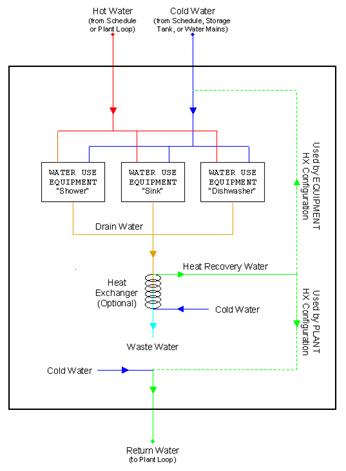
Figure 137. Diagram of internal connections for WaterUse:Connections
The WaterUse:Connections object can be used stand-alone or coupled into a plant loop. In stand-alone mode, the Hot and Cold Water Supply Temperature Schedules override the values for the listed WaterUse:Equipment objects. When coupled to the plant, the Hot Water Supply Temperature Schedule is overridden by the actual plant loop inlet water temperature. When coupled to the plant, the WaterUse:Connections object should be on a Branch object whose control type is set to “Active.”
The unique object name for reference by other objects.
The hot water inlet node when connected to a plant loop. The hot water supplies all of the WaterUse:Equipment objects that demand hot water. Insufficient supply temperature or flow results in cooler water at the tap.
The cold water outlet node, i.e. the cold water supply mains, when connected to a plant loop. The return node provides make-up water for the hot water lost down the drain.
Reference to the WaterUse:Storage object that supplies cold water to the listed WaterUse:Equipment objects. If the field is blank, or the tank is empty, fresh water is supplied from the water mains.
Reference to the WaterUse:Storage object that stores the resulting graywater from the listed WaterUse:Equipment objects. If the field is blank, the graywater is not reclaimed.
Reference to the schedule object specifying the hot water temperature [C]. If blank in stand-alone mode, the hot water supply temperature defaults to the cold water supply temperature. This field (even if blank) overrides the Hot Water Supply Temperature Schedule in all of the listed WaterUse:Equipment objects.
Reference to the schedule object specifying the cold water temperature [C] from the supply mains that provides the cold water to the tap and makes up for all water lost down the drain. If blank, water temperatures are calculated by the Site:WaterMainsTemperature object.
This field (even if blank) overrides the Cold Water Supply Temperature Schedule in all of the listed WaterUse:Equipment objects.
The heat exchanger type to be used for drainwater heat recovery. None indicates no heat recovery is to be simulated. Ideal sets a heat exchanger effectiveness of 1.0. Effectiveness is calculated dynamically for CounterFlow and CrossFlow options.
One popular type of drainwater heat exchanger is the Gravity-Film Heat Exchanger (GFX). The GFX is most closely approximated with the CounterFlow option, but keep in mind that the UA varies more with flow rate for the GFX than for most traditional heat exchangers.
The heat exchanger configuration to be used for drainwater heat recovery. The configuration determines where the heat will be used after it is recovered.
Plant indicates that the all of the recovered heat will be sent to the return flow at the outlet node of the WaterUse:Connections object to preheat the make-up cold water from the water mains.
Equipment indicates that the all of the recovered heat will be used to preheat the cold water flow side of the WaterUse:Equipment objects listed in this WaterUse:Connections object
PlantAndEquipment indicates the recovered heat will be divided between the plant and the WaterUse:Equipment objects, as described above. This is the only option where the flow rates are equal in the drain and the heat exchanger.
The UA is the heat transfer coefficient [W/K] for the heat exchanger and is the product of U, the overall heat transfer coefficient, and A, the heat exchanger surface area.
References to WaterUse:Equipment objects.
IDF examples:
WaterUse:Connections,
Domestic Water Uses, !- Name
Water Eq Inlet Node, !- Inlet Node Name
Water Eq Outlet Node, !- Outlet Node Name
Rainwater Storage, !- Supply Water Storage Tank Name
Graywater Storage, !- Reclamation Water Storage Tank Name
, !- Hot Water Supply Temperature Schedule Name
, !- Cold Water Supply Temperature Schedule Name
CounterFlow, !- Drain Water Heat Exchanger Type
Plant, !- Drain Water Heat Exchanger Destination
1500, !- Drain Water Heat Exchanger U-Factor Times Area {W/K}
Sinks, !- Water Use Equipment 1 Name
Showers, !- Water Use Equipment 2 Name
Dishwasher, !- Water Use Equipment 3 Name
Clotheswasher; !- Water Use Equipment 4 Name
The following output variables are reported for the WaterUse:Connections object:
HVAC,Average,Water Use Connections Hot Water Mass Flow Rate [kg/s]
HVAC,Average,Water Use Connections Cold Water Mass Flow Rate [kg/s]
HVAC,Average,Water Use Connections Total Mass Flow Rate [kg/s]
HVAC,Average,Water Use Connections Drain Mass Flow Rate [kg/s]
HVAC,Average,Water Use Connections Heat Recovery Mass Flow Rate [kg/s]
HVAC,Average,Water Use Connections Hot Water Consumption Rate [m3/s]
HVAC,Average,Water Use Connections Cold Water Consumption Rate [m3/s]
HVAC,Average,Water Use Connections Total Consumption Rate [m3/s]
HVAC,Sum,Water Use Connections Hot Water Consumption [m3]
HVAC,Sum,Water Use Connections Cold Water Consumption [m3]
HVAC,Sum,Water Use Connections Total Consumption [m3]
HVAC,Average,Water Use Connections Hot Water Temperature [C]
HVAC,Average,Water Use Connections Cold Water Temperature [C]
HVAC,Average,Water Use Connections Drain Water Temperature [C]
HVAC,Average,Water Use Connections Return Water Temperature [C]
HVAC,Average,Water Use Connections Waste Water Temperature [C]
HVAC,Average,Water Use Connections Heat Recovery Water Temperature [C]
HVAC,Average,Water Use Connections Heat Recovery Effectiveness []
HVAC,Average,Water Use Connections Heat Recovery Rate [W]
HVAC,Sum,Water Use Connections Heat Recovery Energy [J]
HVAC,Sum,Water Use Connections Plant Hot Water Consumption [J]
The mass flow rate of hot water supplied to all equipment.
The mass flow rate of cold water supplied to all equipment.
The total mass flow rate of water (hot + cold) supplied to all equipment.
The mass flow rate of drainwater from all equipment.
The mass flow rate of make-up water in the heat exchanger.
The volumetric flow rate of hot water supplied to all equipment and consumed down the drain.
The volumetric flow rate of cold water supplied to all equipment and consumed down the drain.
The total volumetric flow rate of water (hot + cold) supplied to all equipment and consumed down the drain.
The volume of hot water supplied to all equipment and consumed down the drain.
The volume of cold water supplied to all equipment and consumed down the drain.
The total volume of water (hot+cold) supplied to all equipment and consumed down the drain.
The temperature of hot water supplied to all equipment.
The temperature of cold water supplied to all equipment.
The water temperature at the drain equal to the mixed water temperature minus any heat losses to the zone.
The temperature of make-up water returned to the plant loop.
The temperature of the water leaving the heat exchanger. If no heat exchanger, the waste water temperature equals the drain water temperature.
The temperature of the water leaving the heat exchanger. If no heat exchanger, the waste water temperature equals the drain water temperature.
The effectiveness value of the heat exchanger.
The heat recovered by the heat exchanger and used to preheat the cold make-up water.
The energy recovered by the heat exchanger and used to preheat the cold make-up water.
The plant loop energy consumed by the hot water used.
The WaterUse:Storage object is a central component for complex water systems. This object is not needed if the only use of water is directly from the mains, or utility service water. If the building model is to include any on-site collection or wells or storing and reuse of graywater, then a WaterUse:Storage is needed. Each WaterUse:Storage can serve as a central node and make connections to numerous sources of supply or numerous components with demand. If a maximum capacity is not specified, the tank is assumed to have unlimited capacity. This is useful for sizing.
Storage tanks may handle a lot of water but show no use. This is because water usage is metered at the component level were water is “used up.” The only water a storage tank might use up is overflow water if it is discarded.
The unique object name for reference by other objects.
Describes the quality of the water contained in the tank. Used for reporting and to check that the uses and supply match the category of water quality.
The maximum volumetric capacity [m3] of the water tank. If blank, this field defaults to unlimited capacity.
The volume of water in the storage tank at the beginning of each simulation environmental period [m3]. This provides a starting point for the amount of water in storage.
The design flow rate [m3/s] of fittings that provide water into the tank from external sources. In a scenario where a heavy rain fall is being harvested, the actual reclamation rate might be limited by pipe size or filtration. If blank, this field defaults to unlimited rate.
The design flow rate [m3/s] of fitting that withdraw water from the tank to end uses. Heavy demand (landscaping?) might be limited by pipe size or filtration. If Blank, this field defaults to unlimited rate.
Name of a second WaterUse:Storage that would receive overflow. Overflow could occur if the maximum capacity is reached or if the design in flow rate is exceeded. If left blank, then the overflow is discarded and lost from the water system.
The storage tank can include the capability of modeling a float valve that will call for water to be added to the tank. This field is used to select the type of system used to respondto fill requests made by a float valve. The available options are ‘None’, ‘Mains’, ‘GroundwaterWell’, or ‘OtherTank.’ The float valve settings are described in the next two fields.
The volumetric capacity [m3] of the water tank when a floating valve would turn on to allow filling the tank.
The volumetric capacity [m3] of the water tank when a floating valve would turn off after having been filling the tank.
The volumetric capacity of the tank that indicates where a secondary float valve will maintain the volume by calling for mains water. Used if the well or other tank cannot keep up with the needs of the main float valve. If left blank or equal 0.0, then there is no mains water backup. If specified, then mains water will be drawn once the storage tank reaches this level and then the mains water will fill all the way to capacity specified in the previous field.
This field contains the name of another WaterUse:Storage defined elsewhere in the input file. This field is only used if the Type of Controlled Supply field is set to ‘OtherTank’ and the current tank is to be configured to be supplied by a second tank in response to a float valve.
Controls the method of determining the temperature of the water in the storage tank. The only available option at the current time is ScheduledTemperature.
Reference to the schedule object specifying the temperature [C] of the water in the tank. This takes the place of a full thermal model of the tank.
Reserved for future use. The field can be Schedule, Zone, or Outdoors.
Reserved for future use. Schedule name for ambient temperature when previous field is Schedule.
Reserved for future use. Name of zone where the tank is located.
Reserved for future zone thermal model.
Reserved for future zone thermal model.
Reserved for future zone thermal model.
IDF examples:
WaterUse:Storage,
Tower 2 water tank, !- Name
Tower water make up Holding tank, !- Water Quality Subcategory
30.0 , !- Maximum Capacity {m3}
10.0 , !- Initial Volume {m3}
20.0, !- Design In Flow Rate {m3}
20.0, !- Design Out Flow Rate {m3}
, !- Overflow Destination
Mains, !- Type of Supply Controlled by Float Valve
8.0 , !- Float Valve On Capacity {m3}
10.0, !- Float Valve Off Capacity {m3}
3.0, !- Backup Mains Capacity {m3}
, !- Other Tank Name
ScheduledTemperature , !- Water Thermal Mode
Water Tank Temp Sched , !- Water Temperature Schedule Name
, !- Ambient Temperature Indicator
, !- Ambient Temperature Schedule Name
, !- Zone Name
, !- Tank Surface Area {m2}
, !- Tank U Value {W/m2-K}
; !- Tank Outside Surface Material Name
The following output variables are available for reporting for each WaterUse:Storage object.
This is the volume of water stored in the storage tank
This is the net rate of flows in and out of the storage tank.
This is the rate of flows into the storage tank
This is the rate of flows out of the storage tank
This is the volume of water drawn from the mains in order to fill the tank.
This is the rate of water draw from the mains in order to fill the tank.
This is the temperature of the water in the tank.
This is the rate of water flows that overflow the tank either because of limits on how fast the tank can fill or because the tank is full and cannot handle the water provided.
This is the volume of water overflowing the tank because of limits on how fast the tank can fill or because the tank is full and cannot handle the water provided.
The WaterUse:RainCollector object is used for harvesting rainwater falling on building surfaces. The rainwater is sent to a WaterUse:Storage object. In order to use this object it is necessary to also include a Site:Precipitation object to describe the rates of rainfall.
The unique object name for reference by other objects.
A reference to a WaterUse:Storage object where the rainwater will be collected and stored for later use.
The WaterUse:RainCollector model includes a loss factor that indicates the portion of incident rain that is not successfully collected. Two modes are available: Constant and Scheduled. Enter Constant in this field for the model to use a simple fixed loss factor defined in the next field. For versatility, the loss factor can follow a schedule by entering Scheduled in this field and then the name of a schedule in the second field below.
Constant loss factor for how much of the incident rainwater is lost and not collected. The factor should be between 0 and 1.
Name of a schedule that defines a variable collection loss factor if the mode is selected as Scheduled.
The maximum flow rate [m3/s] for rainwater collection. In a scenario where a heavy rain fall is being harvested, the actual reclamation rate might be limited by pipe size or the filtration system.
A reference to the name of a surface object which will collect the rain. Typically the collection surfaces would correspond to roof surfaces on the building. The effective area for rainwater collection is the horizontal component (area * cosine of the slope, etc.). More detailed modeling of rainwater collection can be added later to account for factors such as wind speed and direction, etc.
IDF examples:
WaterUse:RainCollector,
My Test Rain Collector ,!- Name
My Test Tank , !- Storage Tank Name
CONSTANT, !- Loss Factor Mode
0.9 , !- Collection Loss Factor
, !- Collection Loss Factor Schedule Name
1.0 , !- Maximum Collection Rate
SouthRoof , !- Collection Surface 1 Name
NorthRoof1, !- Collection Surface 2 Name
NorthRoof3 , !- Collection Surface 3 Name
NorthRoof2 ; !- Collection Surface 4 Name
HVAC,Average,Rainwater Collector Volumetric Rate [m3/s]
HVAC,Sum,Rainwater Collector Water [m3]
These output variables provide the rate and volume of water collected by the WaterUse:RainCollector.
The WaterUse:Well object is for simulating on-site water supply from a well. Well water is pumped out of the ground and into a WaterUse:Storage. The operation of the ground water well is controlled by the associated WaterUse:Storage which is assumed to be operated as a vented cistern with no pressure tank. The current implementation is very simple and only requires two numeric inputs: the rated pump flow and power. A more elaborate well model may be added and many input fields are reserved for this future expansion.
Unique name of this well.
A reference to a WaterUse:Storage object where the rainwater will be collected and stored for later use.
Reserved for future use. Effective depth of well [m]
This is the nominal pump flow rate [m3/s]. This field is required.
Reserved for future use [Pa]. Pump head at rated conditions in Pascals.
This is the pump power at the nominal pump flow rate [W]. This field is required.
Reserved for future use.
Reserved for future use. Rate at which ground water enters well during a sustained draw, e.g., 2 hour well test [m3/s].
Reserved for future use. Capacity in well after long period of inactivity and the usual water table depth. [m3]
Reserved for future use. Two options available: Constant or Scheduled
Reserved for future use. Depth of water table from WaterUse:Storage
Reserved for future use.
An example input object:
WaterUse:Well,
My Test Well, !- Name
Tower 1 Water Tank, !- Storage Tank Name
, !- Pump Depth
0.1, !- Pump Rated Flow Rate {m3/s}
, !- Pump Rated Head {Pa}
120, !- Pump Rated Power Consumption {W}
, !- Pump Efficiency
, !- Well Recovery Rate {m3/s}
, !- Nominal Well Storage Volume {m3}
, !- Water Table Depth Mode
, !- Water Table Depth
; !- Water Table Depth Schedule Name
This group of objects primarily consists of polynomial curves that are used to characterize the performance of HVAC equipment. Several other non-polynomial curves are also included to characterize the performance of pumps and fans. All of the curves are input, stored, and evaluated entirely within the CurveManager module. The curves are usually derived from fits or regressions to data covering a limited range. Results for independent variable values outside this range are likely to be invalid, so curve input always contains a range of validity (maximum and minimum permitted values) for each independent variable and can optionally have limits on the curve ouput. No error or warning message is issued if an independent variable is outside the range. Instead, the curve manager uses the minimum value if an independent variable is less than the minimum, and the maximum if a variable exceeds the maximum. Similarly, no error or warning message is issued if the curve output is outside the range of the optional minimum and maximum curve output limits. Instead, the curve manager uses the minimum and maximum curve limits to cap the output of the performance curve.
Input for the linear curve consists of a curve name, the two coefficients, and the maximum and minimum valid independent variable values. Optional inputs for curve minimum and maximum may be used to limit the output of the performance curve (e.g., limit extrapolation). The equation represented by the linear curve is:
![]()
A user assigned unique name for an instance of a linear curve. When a curve is used, it is referenced by this name.
The constant coefficient (C1) in the equation.
The linear coefficient (C2) in the equation.
The minimum allowable value of x. Values of x less than the minimum will be replaced by the minimum.
The maximum allowable value of x. Values of x greater than the maximum will be replaced by the maximum.
The minimum allowable value of the evaluated curve. Values less than the minimum will be replaced by the minimum.
The maximum allowable value of the evaluated curve. Values greater than the maximum will be replaced by the maximum.
This field is used to indicate the kind of units that may be associated with the x values. It is used by IDF Editor to display the appropriate SI and IP units for the Minimum Value of X and Maximum Value of x. The unit conversion is not applied to the coefficients. The available options are shown below. If none of these options are appropriate, select Dimensionless which will have no unit conversion.
n Dimensionless
n Temperature
n VolumetricFlow
n MassFlow
n Distance
n Power
This field is used to indicate the kind of units that may be associated with the output values. It is used by IDF Editor to display the appropriate SI and IP units for the Minimum Curve Output and Maximum Curve Output. The unit conversion is not applied to the coefficients. The available options are shown below. If none of these options are appropriate, select Dimensionless which will have no unit conversion.
n Dimensionless
n Capacity
n Power
Following is an example input:
Curve:Linear,
Curve-Linear, ! name
-1, ! Coefficient1 Constant
2, ! Coefficient2 x
0.0, ! min curve output
1.0; ! max curve output
The following is another example, as might be applied in the Fan:ComponentModel to characterize duct static pressure reset (using a constant duct static pressure set point of 248.84 Pa in this case):
Curve:Linear,
DiagnosticSPR, ! Curve Name f = C1 + C2*x
248.84, ! Coefficient1 Constant [Pa]
0., ! Coefficent 2 Press/Flow [Pa-s/m3]
0., ! Minimum Value of x (Qfan) [m3/s]
100., ! Maximum Value of x (Qfan) [m3/s]
62.5, ! Minimum Curve Output [Pa]
248.84; ! Maximum Curve Output [Pa]
Input for a quadratic curve consists of the curve name, the three coefficients, and the maximum and minimum valid independent variable values. Optional inputs for curve minimum and maximum may be used to limit the output of the performance curve (e.g., limit extrapolation). The equation represented by the quadratic curve is:
![]()
A user assigned unique name for an instance of a quadratic curve. When a curve is used, it is referenced by this name.
The constant coefficient (C1) in the equation.
The linear coefficient (C2) in the equation.
The quadratic coefficient (C3) in the equation.
The minimum allowable value of x. Values of x less than the minimum will be replaced by the minimum.
The maximum allowable value of x. Values of x greater than the maximum will be replaced by the maximum.
The minimum allowable value of the evaluated curve. Values less than the minimum will be replaced by the minimum.
The maximum allowable value of the evaluated curve. Values greater than the maximum will be replaced by the maximum.
This field is used to indicate the kind of units that may be associated with the x values. It is used by IDF Editor to display the appropriate SI and IP units for the Minimum Value of X and Maximum Value of x. The unit conversion is not applied to the coefficients. The available options are shown below. If none of these options are appropriate, select Dimensionless which will have no unit conversion.
n Dimensionless
n Temperature
n VolumetricFlow
n MassFlow
n Distance
n Power
This field is used to indicate the kind of units that may be associated with the output values. It is used by IDF Editor to display the appropriate SI and IP units for the Minimum Curve Output and Maximum Curve Output. The unit conversion is not applied to the coefficients. The available options are shown below. If none of these options are appropriate, select Dimensionless which will have no unit conversion.
n Dimensionless
n Capacity
n Power
Following is an example input.
Curve:Quadratic,
WindACCBFFFF, ! name
-2.277, ! Coefficient1 Constant
5.2114, ! Coefficient2 x
-1.9344, ! Coefficient3 x**2
0.0, ! Minimum Value of x
1.0; ! Maximum Value of x
Input for a cubic curve consists of the curve name, the 4 coefficients, and the maximum and minimum valid independent variable values. Optional inputs for curve minimum and maximum may be used to limit the output of the performance curve (e.g., limit extrapolation). The equation represented by the cubic curve is:
![]()
A user assigned unique name for an instance of a cubic curve. When a curve is used, it is referenced by this name.
The constant coefficient (C1) in the equation.
The linear coefficient (C2) in the equation.
The quadratic coefficient (C3) in the equation.
The cubic coefficient (C4) in the equation.
The minimum allowable value of x. Values of x less than the minimum will be replaced by the minimum.
The maximum allowable value of x. Values of x greater than the maximum will be replaced by the maximum.
The minimum allowable value of the evaluated curve. Values less than the minimum will be replaced by the minimum.
The maximum allowable value of the evaluated curve. Values greater than the maximum will be replaced by the maximum.
This field is used to indicate the kind of units that may be associated with the x values. It is used by IDF Editor to display the appropriate SI and IP units for the Minimum Value of X and Maximum Value of x. The unit conversion is not applied to the coefficients. The available options are shown below. If none of these options are appropriate, select Dimensionless which will have no unit conversion.
n Dimensionless
n Temperature
n VolumetricFlow
n MassFlow
n Distance
n Power
This field is used to indicate the kind of units that may be associated with the output values. It is used by IDF Editor to display the appropriate SI and IP units for the Minimum Curve Output and Maximum Curve Output. The unit conversion is not applied to the coefficients. The available options are shown below. If none of these options are appropriate, select Dimensionless which will have no unit conversion.
n Dimensionless
n Capacity
n Power
Following is an input example.
Curve:Cubic,
WindACEIRFPLF, ! name
.00000273404, ! Coefficient1 Constant
1.05259, ! Coefficient2 x
-.0552087, ! Coefficient3 x**2
.00262236, ! coeff4
0.0, ! min
1.1; ! max
Input for a Quartic (fourth order polynomial) curve consists of the curve name, the five coefficients, and the maximum and minimum valid independent variable values. Optional inputs for curve minimum and maximum may be used to limit the output of the performance curve (e.g., limit extrapolation). The equation represented by the quartic curve is:
![]()
A user assigned unique name for an instance of a Quartic curve. When a curve is used, it is referenced by this name.
The constant coefficient (C1) in the equation.
The linear coefficient (C2) in the equation.
The quadratic coefficient (C3) in the equation.
The cubic coefficient (C4) in the equation.
The fourth-order coefficient (C5) in the equation.
The minimum allowable value of x. Values of x less than the minimum will be replaced by the minimum.
The maximum allowable value of x. Values of x greater than the maximum will be replaced by the maximum.
The minimum allowable value of the evaluated curve. Values less than the minimum will be replaced by the minimum.
The maximum allowable value of the evaluated curve. Values greater than the maximum will be replaced by the maximum.
This field is used to indicate the kind of units that may be associated with the x values. It is used by IDF Editor to display the appropriate SI and IP units for the Minimum Value of X and Maximum Value of x. The unit conversion is not applied to the coefficients. The available options are shown below. If none of these options are appropriate, select Dimensionless which will have no unit conversion.
n Dimensionless
n Temperature
n VolumetricFlow
n MassFlow
n Distance
n Power
This field is used to indicate the kind of units that may be associated with the output values. It is used by IDF Editor to display the appropriate SI and IP units for the Minimum Curve Output and Maximum Curve Output. The unit conversion is not applied to the coefficients. The available options are shown below. If none of these options are appropriate, select Dimensionless which will have no unit conversion.
n Dimensionless
n Capacity
n Power
Following is an input example.
Curve:Quartic,
BGSeries60, !- y = -611.41x4 + 192.68x3 - 88.843x2 + 4.7634x + 5.5656
5.5656, !- Constant
4.7634, !- 1st coefficient
-88.843, !- 2nd coefficient
192.68, !- 3rd coefficient
-611.41, !- 4th coefficient
0.0, !- Min Phi Value
0.2412; !- Max Phi Value
The following is another example, as might be applied in the Fan:ComponentModel to characterize belt maximum efficiency (using a medium efficiency belt in this case):
Curve:Quartic,
BeltMaxEffMedium, ! Curve Name
-0.09504, ! CoefficientC1
0.03415, ! CoefficientC2
-0.008897, ! CoefficientC3
0.001159, ! CoefficientC4
-0.00006132, ! CoefficientC5
-1.2, ! Minimum Value of x
6.2, ! Maximum Value of x
-4.6, ! Minimum Curve Output
0.; ! Maximum Curve Output
Input for a exponent curve consists of the curve name, the 3 coefficients, and the maximum and minimum valid independent variable values. Optional inputs for curve minimum and maximum may be used to limit the output of the performance curve (e.g., limit extrapolation). The equation represented by the exponent curve is:
![]()
A user assigned unique name for an instance of an exponent curve. When a curve is used, it is referenced by this name.
The constant coefficient (C1) in the equation.
The linear coefficient (C2) in the equation.
The exponent coefficient (C3) in the equation.
The minimum allowable value of x. Values of x less than the minimum will be replaced by the minimum.
The maximum allowable value of x. Values of x greater than the maximum will be replaced by the maximum.
The minimum allowable value of the evaluated curve. Values less than the minimum will be replaced by the minimum.
The maximum allowable value of the evaluated curve. Values greater than the maximum will be replaced by the maximum.
This field is used to indicate the kind of units that may be associated with the x values. It is used by IDF Editor to display the appropriate SI and IP units for the Minimum Value of X and Maximum Value of x. The unit conversion is not applied to the coefficients. The available options are shown below. If none of these options are appropriate, select Dimensionless which will have no unit conversion.
n Dimensionless
n Temperature
n VolumetricFlow
n MassFlow
n Distance
n Power
This field is used to indicate the kind of units that may be associated with the output values. It is used by IDF Editor to display the appropriate SI and IP units for the Minimum Curve Output and Maximum Curve Output. The unit conversion is not applied to the coefficients. The available options are shown below. If none of these options are appropriate, select Dimensionless which will have no unit conversion.
n Dimensionless
n Capacity
n Power
Following is an input example.
Curve:Exponent,
! Curve = C1 + C2*x**C3, x = fan speed ratio
FanPowerExponentCurve, !- Name
0.0, !- Coefficient1 Constant
1.0, !- Coefficient2 Constant
3.0, !- Coefficient3 Constant
0.0, !- Minimum Value of x
1.5, !- Maximum Value of x
0.1, !- Minimum Curve Output
1.5; !- Maximum Curve Output
This curve type is a function of two independent variables. Input consists of the curve name, the ten coefficients, and the minimum and maximum values for each of the independent variables. Optional inputs for curve minimum and maximum may be used to limit the output of the performance curve (e.g., limit extrapolation). The equation represented by the bicubic curve is:
![]()
A user assigned unique name for an instance of a bicubic curve. When a curve is used by another object, it is referenced by this name.
The constant coefficient (C1) in the equation.
The coefficient C2 in the equation.
The coefficient C3 in the equation.
The coefficient C4 in the equation.
The coefficient C5 in the equation.
The coefficient C6 in the equation.
The coefficient C7 in the equation.
The coefficient C8 in the equation.
The coefficient C9 in the equation.
The coefficient C10 in the equation.
The minimum allowable value of x. Values of x less than this minimum will be replaced by the minimum.
The maximum allowable value of x. Values of x greater than this maximum will be replaced by the maximum.
The minimum allowable value of y. Values of y less than this minimum will be replaced by the minimum.
The maximum allowable value of y. Values of y greater than this maximum will be replaced by the maximum.
The minimum allowable value of the evaluated curve. Values less than the minimum will be replaced by the minimum.
The maximum allowable value of the evaluated curve. Values greater than the maximum will be replaced by the maximum.
This field is used to indicate the kind of units that may be associated with the x values. It is used by IDF Editor to display the appropriate SI and IP units for the Minimum Value of X and Maximum Value of x. The unit conversion is not applied to the coefficients. The available options are shown below. If none of these options are appropriate, select Dimensionless which will have no unit conversion.
n Dimensionless
n Temperature
n VolumetricFlow
n MassFlow
n Power
n Distance
This field is used to indicate the kind of units that may be associated with the y values. It is used by IDF Editor to display the appropriate SI and IP units for the Minimum Value of Y and Maximum Value of Y. The unit conversion is not applied to the coefficients. The available options are shown below. If none of these options are appropriate, select Dimensionless which will have no unit conversion.
n Dimensionless
n Temperature
n VolumetricFlow
n MassFlow
n Power
n Distance
This field is used to indicate the kind of units that may be associated with the output values. It is used by IDF Editor to display the appropriate SI and IP units for the Minimum Curve Output and Maximum Curve Output. The unit conversion is not applied to the coefficients. The available options are shown below. If none of these options are appropriate, select Dimensionless which will have no unit conversion.
n Dimensionless
n Capacity
n Power
Below is an example input.
Curve:Bicubic,
Main Chiller EIRFPLR, !- Name
7.086284E-02, !- Coefficient1 Constant
2.787561E-03, !- Coefficient2 x
-8.917038E-06, !- Coefficient3 x**2
2.309734E-01, !- Coefficient4 y
1.250442E+00, !- Coefficient5 y**2
-2.161029E-03, !- Coefficient6 x*y
0.000000E+00, !- Coefficient7 x**3
-5.630094E-01, !- Coefficient8 y**3
0.000000E+00, !- Coefficient9 x**2*y
0.000000E+00, !- Coefficient10 x*y**2
20.33, !- Minimum Value of x
35.00, !- Maximum Value of x
0.25, !- Minimum Value of y
1.01; !- Maximum Value of y
This curve is a function of two independent variables. Input consists of the curve name, the six coefficients, and min and max values for each of the independent variables. Optional inputs for curve minimum and maximum may be used to limit the output of the performance curve (e.g., limit extrapolation). The equation represented by the bicubic curve is:
![]()
A user assigned unique name for an instance of a biquadratic curve. When a curve is used, it is referenced by this name.
The constant coefficient (C1) in the equation.
The coefficient C2 in the equation.
The coefficient C3 in the equation.
The coefficient C4 in the equation.
The coefficient C5 in the equation.
The coefficient C6 in the equation.
The minimum allowable value of x. Values of x less than the minimum will be replaced by the minimum.
The maximum allowable value of x. Values of x greater than the maximum will be replaced by the maximum.
The minimum allowable value of y. Values of y less than the minimum will be replaced by the minimum.
The maximum allowable value of y. Values of y greater than the maximum will be replaced by the maximum.
The minimum allowable value of the evaluated curve. Values less than the minimum will be replaced by the minimum.
The maximum allowable value of the evaluated curve. Values greater than the maximum will be replaced by the maximum.
This field is used to indicate the kind of units that may be associated with the x values. It is used by IDF Editor to display the appropriate SI and IP units for the Minimum Value of X and Maximum Value of x. The unit conversion is not applied to the coefficients. The available options are shown below. If none of these options are appropriate, select Dimensionless which will have no unit conversion.
n Dimensionless
n Temperature
n VolumetricFlow
n MassFlow
n Power
n Distance
This field is used to indicate the kind of units that may be associated with the y values. It is used by IDF Editor to display the appropriate SI and IP units for the Minimum Value of Y and Maximum Value of Y. The unit conversion is not applied to the coefficients. The available options are shown below. If none of these options are appropriate, select Dimensionless which will have no unit conversion.
n Dimensionless
n Temperature
n VolumetricFlow
n MassFlow
n Power
n Distance
This field is used to indicate the kind of units that may be associated with the output values. It is used by IDF Editor to display the appropriate SI and IP units for the Minimum Curve Output and Maximum Curve Output. The unit conversion is not applied to the coefficients. The available options are shown below. If none of these options are appropriate, select Dimensionless which will have no unit conversion.
n Dimensionless
n Capacity
n Power
Below is an example input.
Curve:Biquadratic,
WindACCoolCapFT, ! name
0.942587793, ! Coefficient1 Constant
0.009543347, ! Coefficient2 x
0.000683770, ! Coefficient3 x**2
-0.011042676, ! Coefficient4 y
0.000005249, ! Coefficient5 y**2
-0.000009720, ! Coefficient6 x*y
15., 22., ! min and max of first independent variable
29., 47.; ! min and max of second independent variable
This curve is a function of two independent variables. Input consists of the curve name, the six coefficients, and min and max values for each of the independent variables. Optional inputs for curve minimum and maximum may be used to limit the output of the performance curve (e.g., limit extrapolation). The equation represented by the quadratic linear curve:
![]()
A user assigned unique name for an instance of a quadratic-linear curve. When a curve is used, it is referenced by this name.
The constant coefficient (C1) in the equation.
The coefficient C2 in the equation.
The coefficient C3 in the equation.
The coefficient C4 in the equation.
The coefficient C5 in the equation.
The coefficient C6 in the equation.
The minimum allowable value of x. Values of x less than the minimum will be replaced by the minimum.
The maximum allowable value of x. Values of x greater than the maximum will be replaced by the maximum.
The minimum allowable value of y. Values of y less than the minimum will be replaced by the minimum.
The maximum allowable value of y. Values of y greater than the maximum will be replaced by the maximum.
The minimum allowable value of the evaluated curve. Values less than the minimum will be replaced by the minimum.
The maximum allowable value of the evaluated curve. Values greater than the maximum will be replaced by the maximum.
This field is used to indicate the kind of units that may be associated with the x values. It is used by IDF Editor to display the appropriate SI and IP units for the Minimum Value of X and Maximum Value of x. The unit conversion is not applied to the coefficients. The available options are shown below. If none of these options are appropriate, select Dimensionless which will have no unit conversion.
n Dimensionless
n Temperature
n VolumetricFlow
n MassFlow
n Power
n Distance
This field is used to indicate the kind of units that may be associated with the y values. It is used by IDF Editor to display the appropriate SI and IP units for the Minimum Value of Y and Maximum Value of Y. The unit conversion is not applied to the coefficients. The available options are shown below. If none of these options are appropriate, select Dimensionless which will have no unit conversion.
n Dimensionless
n Temperature
n VolumetricFlow
n MassFlow
n Power
n Distance
This field is used to indicate the kind of units that may be associated with the output values. It is used by IDF Editor to display the appropriate SI and IP units for the Minimum Curve Output and Maximum Curve Output. The unit conversion is not applied to the coefficients. The available options are shown below. If none of these options are appropriate, select Dimensionless which will have no unit conversion.
n Dimensionless
n Capacity
n Power
Below is an example input.
Curve:QuadraticLinear,
DischargeCurve, !- Curve Name
0.0, !- Coefficient1 Constant
0.09, !- Coefficient2 x
-0.15, !- Coefficient3 x**2
0.612, !- Coefficient4 y
-0.324, !- Coefficient5 x*y
-0.216, !- Coefficient6 x**2*y
0.0, !- Minimum Value of x
1.0, !- Maximum Value of x
0.0, !- Minimum Value of y
9.9; !- Maximum Value of y
This curve is a 2nd order polynomial function of three variable polynomial independent variables. Input consists of the curve name, the twenty seven coefficients, and min and max values for each of the independent variables. Optional inputs for curve minimum and maximum may be used to limit the output of the performance curve (e.g., limit extrapolation). The equation represented by the triquadratic curve:
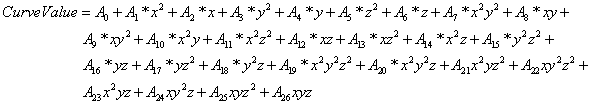
The constant coefficient (A0) in the equation.
The coefficient (A1) in the equation.
The coefficient (A2) in the equation.
The coefficient (A3) in the equation.
The coefficient (A4) in the equation.
The coefficient (A5) in the equation.
The coefficient (A6) in the equation.
The coefficient (A7) in the equation.
The coefficient (A8) in the equation.
The coefficient (A9) in the equation.
The coefficient (A10) in the equation.
The coefficient (A11) in the equation.
The coefficient (A12) in the equation.
The coefficient (A13) in the equation.
The coefficient (A14) in the equation.
The coefficient (A15) in the equation.
The coefficient (A16) in the equation.
The coefficient (A17) in the equation.
The coefficient (A18) in the equation.
The coefficient (A19) in the equation.
The coefficient (A20) in the equation.
The coefficient (A21) in the equation.
The coefficient (A22) in the equation.
The coefficient (A23) in the equation.
The coefficient (A24) in the equation.
The coefficient (A25) in the equation.
The coefficient (A26) in the equation.
The minimum allowable value of x. Values of x less than the minimum will be replaced by the minimum.
The maximum allowable value of x. Values of x greater than the maximum will be replaced by the maximum.
The minimum allowable value of y. Values of y less than the minimum will be replaced by the minimum.
The maximum allowable value of y. Values of y greater than the maximum will be replaced by the maximum.
The minimum allowable value of z. Values of z less than the minimum will be replaced by the minimum.
The maximum allowable value of z. Values of z greater than the maximum will be replaced by the maximum.
The minimum allowable value of the evaluated curve. Values less than the minimum will be replaced by the minimum.
The maximum allowable value of the evaluated curve. Values greater than the maximum will be replaced by the maximum.
This field is used to indicate the kind of units that may be associated with the x values. It is used by IDF Editor to display the appropriate SI and IP units for the Minimum Value of X and Maximum Value of x. The unit conversion is not applied to the coefficients. The available options are shown below. If none of these options are appropriate, select Dimensionless which will have no unit conversion.
n Dimensionless
n Temperature
n VolumetricFlow
n MassFlow
n Power
n Distance
This field is used to indicate the kind of units that may be associated with the y values. It is used by IDF Editor to display the appropriate SI and IP units for the Minimum Value of Y and Maximum Value of Y. The unit conversion is not applied to the coefficients. The available options are shown below. If none of these options are appropriate, select Dimensionless which will have no unit conversion.
n Dimensionless
n Temperature
n VolumetricFlow
n MassFlow
n Power
n Distance
This field is used to indicate the kind of units that may be associated with the z values. It is used by IDF Editor to display the appropriate SI and IP units for the Minimum Value of Z and Maximum Value of Z. The unit conversion is not applied to the coefficients. The available options are shown below. If none of these options are appropriate, select Dimensionless which will have no unit conversion.
n Dimensionless
n Temperature
n VolumetricFlow
n MassFlow
n Power
n Distance
This field is used to indicate the kind of units that may be associated with the output values. It is used by IDF Editor to display the appropriate SI and IP units for the Minimum Curve Output and Maximum Curve Output. The unit conversion is not applied to the coefficients. The available options are shown below. If none of these options are appropriate, select Dimensionless which will have no unit conversion.
n Dimensionless
n Capacity
n Power
Input for a pressure drop curve consists of the curve name, a varying number of parameters, and the maximum and minimum valid independent variable values. The equation represented by the pressure drop curve is:
![]()
A user assigned unique name for an instance of a pressure drop curve. When a curve is used, it is referenced by this name.
This diameter represents an equivalent diameter for the given branch. This is parameter (D) in the equation, and has units of {m}. Since varying components may be found on the same branch, this value must be selected along with the other inputs in order to provide a proper value of pressure drop. This is used to calculate the velocity in addition to being used directly in the frictional pressure drop calculation.
This is the pressure drop coefficient typically applied to components such as fittings and occasionally heat pumps. This is parameter (K) in the equation and is dimensionless. This coefficient is used to describe the amount of dynamic pressure lost during the process. This value may be left blank if the user only wants to account for frictional losses in this branch.
This is the length of a pressure drop process in which friction is applied. This is parameter (L) in the equation and has units of {m}. In a pipe, this would be the length of the pipe, however in many cases, pressure drop in other components are applied as an “equivalent length.” This is only required if the user is wanting to perform frictional pressure drop calculations.
This field represents the first method to simulate frictional losses. This parameter does not appear directly in the equation above, as it is only used to develop the friction factor (f), but the roughness will have units of {m} if entered. If the user enters this roughness value, the pressure system will use it along with an approximation to the Moody chart to estimate the friction factor given the current flow conditions. This allows the friction calculate to be dynamic throughout the simulation.
This field represents the second method to simulate frictional losses. This is parameter (f) in the equation and is dimensionless. This parameter is a fixed value of friction factor which would override any calculations performed based on roughness, etc. If the user has a known friction factor for a given component, this is where it should be entered.
Following is an input example.
Curve:Functional:PressureDrop,
PressureMinorAndFriction,!- Name
0.05, !- Diameter
53.8, !- Minor Loss Coefficient
200, !- Length
, !- Roughness
0.008; !- Fixed Friction Factor
Input for the fan total pressure rise curve consists of the curve name, the four coefficients, and the maximum and minimum valid independent variable values. Optional inputs for the curve minimum and maximum may be used to limit the output of the performance curve (e.g., limit extrapolation). The equation is:
![]()
where ΔPfan,tot is the fan total pressure rise (Pa) as a function of volumetric flow through the fan (Qfan, m3/s), duct static pressure set point (Psm, Pa), and static pressure surrounding the ducts (Po, Pa). Po is assumed to be zero.
The first term of the curve looks like the common system curve in which the fan pressure rise is proportional to the square of the fan flow, but here it also depends implicitly on supply and return pressure losses, and in part on the fraction of the fan flow that is outdoor air (essentially “leaks” into and out of the return side of the system). Very often it is the only term considered, but that would only be correct with fixed-position dampers, no distribution system leakage, no linear resistance components, and no duct static pressure control.
The second term accounts for significant flow resistances in the system where the pressure difference is linearly proportional to the flow. Some filters and coils in the return may need this term to be adequately described. This term could be ignored if there are no linear components or if their pressure drops are very small compared to the other terms.
The third term, which depends on the fan flow and square root of the supply duct pressure Psm, accounts in part for leakage from the supply system when damper positions are fixed or are changed independently of static pressure or fan flow. In this case, reducing or eliminating supply leakage results in a different system curve. This, however, might be only a minor “correction” to the simple system curves generally used. The third term is zero when the VAV box dampers are modulated to control flow. Consequently, with variable-position supply dampers, reducing or eliminating supply leakage does not change the system curve.
The last term also accounts in part for leakage from the supply system when damper positions are fixed or are changed independently of static pressure or fan flow. This term indicates that the same fan pressure rise can be achieved by raising the duct pressure and closing dampers. The only change in the system in such a case is that the leakage flow may increase. The coefficient for this term is one when the VAV box dampers are modulated to control flow. In both cases, this term may be the most important “correction” to the simple system curves generally used, especially at low flows.
The required user-assigned unique alpha name for an instance of this curve. When a curve of this type is used, it is referenced by this name.
The required numeric constant coefficient C1 (Pa s2/m6) in the curve. Must be greater than zero.
The required numeric constant coefficient C2 (Pa s/m3) in the curve.
The required numeric constant coefficient C3 (Pa0.5 s/m3) in the curve.
The required numeric constant coefficient C4 (dimensionless) in the curve.
The required numeric minimum allowable value of Qfan (m3/s). Values of Qfan less than the minimum will be replaced within this curve by the minimum.
The required numeric maximum allowable value of Qfan (m3/s). Values of Qfan greater than the maximum will be replaced within this curve by the maximum.
The required numeric minimum allowable value of Psm (Pa). Values of Psm less than the minimum will be replaced within this curve by the minimum.
The required numeric maximum allowable value of Psm (Pa). Values of Psm greater than the maximum will be replaced within this curve by the maximum.
The optional numeric minimum allowable value of the evaluated curve (Pa). Values less than the minimum will be replaced within this curve by the minimum.
The optional numeric maximum allowable value of the evaluated curve (Pa). Values greater than the maximum will be replaced within this curve by the maximum.
The following is an input example describing the fan total pressure rise for a VAV system with a constant non-zero duct static pressure set point (the set point is described separately; see the Curve:Linear object for a related example):
Curve:FanPressureRise,
VSD Example, ! Curve Name f = C1*Qfan**2+C2*Qfan+C3*Qfan*(Psm-Po)**0.5+C4*(Psm-Po) with Po=0
1446.75833497653, ! CoefficientC1 Alpha [Pa s2/m6]
0., ! CoefficientC2 Beta [Pa s/m3]
0., ! CoefficientC3 Gamma [Pa0.5 s/m3]
1., ! CoefficientC4 Delta [-]
0., ! Minimum Value of Qfan [m3/s]
100., ! Maximum Value of Qfan [m3/s]
62.5, ! Minimum Value of Psm [Pa]
300., ! Maximum Value of Psm [Pa]
0.; ! Minimum Curve Output [Pa]
5000.; ! Maximum Curve Output [Pa]
Input for the exponential-modified skew normal curve consists of the curve name, the four coefficients, and the maximum and minimum valid independent variable values. Optional inputs for the curve minimum and maximum may be used to limit the output of the performance curve (e.g., limit extrapolation). The equation is:
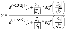
where Z1 = (x – C1) / C2; Z2 = [(exp(C3*x) * C4*x) - C1] / C2; Z3 = -C1 / C2
The required user-assigned unique alpha name for an instance of this curve. When a curve of this type is used, it is referenced by this name.
The required numeric constant coefficient C1 in the curve.
The required numeric constant coefficient C2 in the curve. Must be non-zero.
The required numeric constant coefficient C3 in the curve.
The required numeric constant coefficient C4 in the curve.
The required numeric minimum allowable value of x. Values of x less than the minimum will be replaced by the minimum.
The required numeric maximum allowable value of x. Values of x greater than the maximum will be replaced by the maximum.
The optional numeric minimum allowable value of the evaluated curve. Values less than the minimum will be replaced by the minimum.
The optional numeric maximum allowable value of the evaluated curve. Values greater than the maximum will be replaced by the maximum.
This optional field is provided for future purposes so that the IDF Editor could display the appropriate SI or IP units for the Minimum Value of x and Maximum Value of x (currently dimensionless). At this time, only the Dimensionless option is provided so that no unit conversion is used for this curve.
This optional field is provided for future purposes so that the IDF Editor could display the appropriate SI or IP units for the Minimum Curve Output and Maximum Curve Output (currently dimensionless). At this time, only the Dimensionless option is provided so that no unit conversion is used for this curve.
The following are input examples describing the normalized fan efficiency for the normal (non-stall) and stall operating regions of a backward-curved airfoil centrifugal fan:
Curve:ExponentialSkewNormal,
FanEff120CPLANormal, ! Curve Name
0.072613, ! CoefficientC1 Afan
0.833213, ! CoefficientC2 Bfan
0., ! CoefficientC3 Cfan
0.013911, ! CoefficientC4 Dfan
-4., ! Minimum Value of x
5., ! Maximum Value of x
0.1, ! Minimum Curve Output
1.; ! Maximum Curve Output
Curve:ExponentialSkewNormal,
FanEff120CPLAStall, ! Curve Name
-1.674931, ! CoefficientC1 Afan
1.980182, ! CoefficientC2 Bfan
0., ! CoefficientC3 Cfan
1.844950, ! CoefficientC4 Dfan
-4., ! Minimum Value of x
5., ! Maximum Value of x
0.1, ! Minimum Curve Output
1.; ! Maximum Curve Output
Input for the sigmoid curve consists of the curve name, the five coefficients, and the maximum and minimum valid independent variable values. Optional inputs for the curve minimum and maximum may be used to limit the output of the performance curve (e.g., limit extrapolation). The equation is:

The required user-assigned unique alpha name for an instance of this curve. When a curve of this type is used, it is referenced by this name.
The required numeric constant coefficient C1 in the equation.
The required numeric constant coefficient C2 in the equation.
The required numeric constant coefficient C3 in the equation.
The required numeric constant coefficient C4 in the equation.
The required numeric constant coefficient C5 in the equation.
The required numeric minimum allowable value of x. Values of x less than the minimum will be replaced by the minimum.
The required numeric maximum allowable value of x. Values of x greater than the maximum will be replaced by the maximum.
The optional numeric minimum allowable value of the evaluated curve. Values less than the minimum will be replaced by the minimum.
The optional numeric maximum allowable value of the evaluated curve. Values greater than the maximum will be replaced by the maximum.
This optional field is provided for future purposes so that the IDF Editor could display the appropriate SI or IP units for the Minimum Value of x and Maximum Value of x (currently dimensionless). At this time, only the Dimensionless option is provided so that no unit conversion is used for this curve.
This optional field is provided for future purposes so that the IDF Editor could display the appropriate SI or IP units for the Minimum Curve Output and Maximum Curve Output (currently dimensionless). At this time, only the Dimensionless option is provided so that no unit conversion is used for this curve.
The following are input examples describing the normalized dimensionless flow for normal (non-stall) and stall operating regions of a backward-curved airfoil centrifugal fan:
Curve:Sigmoid,
FanDimFlowNormal, ! Curve Name
0., ! CoefficientC1 Aspd
1.001423, ! CoefficientC2 Bspd
0.123935, ! CoefficientC3 Cspd
-0.476026, ! CoefficientC4 Dspd
1., ! CoefficientC5 Espd
-4., ! Minimum Value of x
5., ! Maximum Value of x
0.05, ! Minimum Curve Output
1.; ! Maximum Curve Output
Curve:Sigmoid,
FanDimFlowStall, ! Curve Name
0., ! CoefficientC1 Aspd
5.924993, ! CoefficientC2 Bspd
-1.91636, ! CoefficientC3 Cspd
-0.851779, ! CoefficientC4 Dspd
1., ! CoefficientC5 Espd
-4., ! Minimum Value of x
5., ! Maximum Value of x
0.05, ! Minimum Curve Output
1.; ! Maximum Curve Output
Input for the single rectangular hyperbola type 1 curve consists of the curve name, the three coefficients, and the maximum and minimum valid independent variable values. Optional inputs for the curve minimum and maximum may be used to limit the output of the performance curve (e.g., limit extrapolation). The equation is:
y = (C1·* x) / (C2+x) + C3
The required user-assigned unique alpha name for an instance of this curve. When a curve of this type is used, it is referenced by this name.
The required numeric constant coefficient C1 in the equation.
The required numeric constant coefficient C2 in the equation.
The required numeric constant coefficient C3 in the equation.
The required numeric minimum allowable value of x. Values of x less than the minimum will be replaced by the minimum.
The required numeric maximum allowable value of x. Values of x greater than the maximum will be replaced by the maximum.
The optional numeric minimum allowable value of the evaluated curve. Values less than the minimum will be replaced by the minimum.
The optional numeric maximum allowable value of the evaluated curve. Values greater than the maximum will be replaced by the maximum.
This optional field is provided for future purposes so that the IDF Editor could display the appropriate SI or IP units for the Minimum Value of x and Maximum Value of x (currently dimensionless). At this time, only the Dimensionless option is provided so that no unit conversion is used for this curve.
This optional field is provided for future purposes so that the IDF Editor could display the appropriate SI or IP units for the Minimum Curve Output and Maximum Curve Output (currently dimensionless). At this time, only the Dimensionless option is provided so that no unit conversion is used for this curve.
The following is an input example describing the maximum efficiency variation for a “mid- or average-efficiency” type of motor:
Curve:RectangularHyperbola1,
MotorMaxEffAvg, ! Curve Name
0.29228, ! CoefficientC1
3.368739, ! CoefficientC2
0.762471, ! CoefficientC3
0., ! Minimum Value of x
7.6, ! Maximum Value of x
0.01, ! Minimum Curve Output
1.; ! Maximum Curve Output
Input for the single rectangular hyperbola type 2 curve consists of the curve name, the three coefficients, and the maximum and minimum valid independent variable values. Optional inputs for the curve minimum and maximum may be used to limit the output of the performance curve (e.g., limit extrapolation). The equation is:
y = (C1·* x) / (C2+x) + C3·* x
The required user-assigned unique alpha name for an instance of this curve. When a curve of this type is used, it is referenced by this name.
The required numeric constant coefficient C1 in the equation.
The required numeric constant coefficient C2 in the equation.
The required numeric constant coefficient C3 in the equation.
The required numeric minimum allowable value of x. Values of x less than the minimum will be replaced by the minimum.
The required numeric maximum allowable value of x. Values of x greater than the maximum will be replaced by the maximum.
The optional numeric minimum allowable value of the evaluated curve. Values less than the minimum will be replaced by the minimum.
The optional numeric maximum allowable value of the evaluated curve. Values greater than the maximum will be replaced by the maximum.
This optional field is provided for future purposes so that the IDF Editor could display the appropriate SI or IP units for the Minimum Value of x and Maximum Value of x (currently dimensionless). At this time, only the Dimensionless option is provided so that no unit conversion is used for this curve.
This optional field is provided for future purposes so that the IDF Editor could display the appropriate SI or IP units for the Minimum Curve Output and Maximum Curve Output (currently dimensionless). At this time, only the Dimensionless option is provided so that no unit conversion is used for this curve.
The following are input examples describing part-load efficiency variations for a “medium efficiency” type of V-belt (Regions 1 and 3), for a “mid- or average-efficiency” nominal 25 hp 4-pole motor, and a nominal 30 hp VFD:
Curve:RectangularHyperbola2,
BeltPartLoadRegion1, ! Curve Name
0.920797, ! CoefficientC1
0.0262686, ! CoefficientC2
0.151594, ! CoefficientC3
0., ! Minimum Value of x
1., ! Maximum Value of x
0.01, ! Minimum Curve Output
1.; ! Maximum Curve Output
Curve:RectangularHyperbola2,
BeltPartLoadRegion3, ! Curve Name
1.037778, ! CoefficientC1
0.0103068, ! CoefficientC2
-0.0268146, ! CoefficientC3
0., ! Minimum Value of x
1., ! Maximum Value of x
0.01, ! Minimum Curve Output
1.; ! Maximum Curve Output
Curve:RectangularHyperbola2,
MotorPartLoad, ! Curve Name
1.137209, ! CoefficientC1
0.0502359, ! CoefficientC2
-0.0891503, ! CoefficientC3
0., ! Minimum Value of x
1., ! Maximum Value of x
0.01, ! Minimum Curve Output
1.; ! Maximum Curve Output
Curve:RectangularHyperbola2,
VFDPartLoad, ! Curve Name
0.987405, ! CoefficientC1
0.0155361, ! CoefficientC2
-0.0059365, ! CoefficientC3
0., ! Minimum Value of x
1., ! Maximum Value of x
0.01, ! Minimum Curve Output
1.; ! Maximum Curve Output
Input for the exponential decay curve consists of the curve name, the three coefficients, and the maximum and minimum valid independent variable values. Optional inputs for the curve minimum and maximum may be used to limit the output of the performance curve (e.g., limit extrapolation). The equation is:
y = C1 + C2 * exp(C3 * x)
The required user-assigned unique alpha name for an instance of this curve. When a curve of this type is used, it is referenced by this name.
The required numeric constant coefficient C1 in the equation.
The required numeric constant coefficient C2 in the equation.
The required numeric constant coefficient C3 in the equation.
The required numeric minimum allowable value of x. Values of x less than the minimum will be replaced by the minimum.
The required numeric maximum allowable value of x. Values of x greater than the maximum will be replaced by the maximum.
The optional numeric minimum allowable value of the evaluated curve. Values less than the minimum will be replaced by the minimum.
The optional numeric maximum allowable value of the evaluated curve. Values greater than the maximum will be replaced by the maximum.
This optional field is provided for future purposes so that the IDF Editor could display the appropriate SI or IP units for the Minimum Value of x and Maximum Value of x (currently dimensionless). At this time, only the Dimensionless option is provided so that no unit conversion is used for this curve.
This optional field is provided for future purposes so that the IDF Editor could display the appropriate SI or IP units for the Minimum Curve Output and Maximum Curve Output (currently dimensionless). At this time, only the Dimensionless option is provided so that no unit conversion is used for this curve.
The following is an input example describing the part-load efficiency variation for a “medium efficiency” type of V-belt (Region 2):
Curve:ExponentialDecay,
BeltPartLoadRegion2, ! Curve Name
1.011965, ! CoefficientC1
-0.339038, ! CoefficientC2
-3.43626, ! CoefficientC3
0., ! Minimum Value of x
1., ! Maximum Value of x
0.01, ! Minimum Curve Output
1.; ! Maximum Curve Output
Input for the double exponential decay curve consists of the curve name, the five coefficients, and the maximum and minimum valid independent variable values. Optional inputs for the curve include the minimum and maximum output of the performance curve. The equation is:
![]()
This field indicates the required user-assigned name for an instance of this curve. When a curve of this type is used, it is referenced by this name.
The required numeric constant coefficient C1 in the equation.
The required numeric constant coefficient C2 in the equation.
The required numeric constant coefficient C3 in the equation.
The required numeric constant coefficient C4 in the equation.
The required numeric constant coefficient C5 in the equation.
The required numeric minimum allowable value of x. Values of x less than the minimum will be replaced by the minimum
The required numeric maximum allowable value of x. Values of x greater than the maximum will be replaced by the maximum
The optional numeric minimum allowable value of the evaluated curve. Values less than the minimum will be replaced by the minimum
The optional numeric maximum allowable value of the evaluated curve. Values greater than the maximum will be replaced by the maximum
The optional field is provided for future purposes so that the IDF Editor could display the appropriate SI or IP units for the Minimum and Maximum Value of x. Currently, only Dimensionless option is provided so that no unit conversion is used for this curve
The optional field is provided for future purposes so that the IDF Editor could display the appropriate SI or IP units for the Minimum and Maximum Curve Ouput. Currently, only Dimensionless option is provided so that no unit conversion is used for this curve.
An example input of the Curve:DoubleExponentialDecay input is:
Curve:DoubleExponentialDecay,
BatteryCycleCurve, !- Name
1380, !- Coefficient1 C1
6834, !- Coefficient2 C2
-8.75, !- Coefficient3 C3
6747, !- Coefficient4 C4
-6.22, !- Coefficient5 C5
0, !- Minimum Value of x
1.0; !- Maximum Value of x
The current value of the performance curve. This value is averaged over the time step being reported. Inactive or unused performance curves will show a value of -999 (e.g., equipment is off, a specific performance curve is not required for this aspect of the equipment model at this time step, etc.). This value means that the performance curve was not called during the simulation and, therefore, not evaluated. This inactive state value is only set at the beginning of each environment. When averaging over long periods of time, this inactive state value may skew results. In this case, use a detaled reporting frequency (ref. Output:Variable) to view results at each HVAC time step.
The current value of the nth independent variable passed to the performance curve. The order of the independent variables is in the same order as the model equation represented by this performance curve object. This value is averaged over the time step being reported.
HVAC,Average,Performance Curve Output []
HVAC,Average,Performance Curve Input 1 []
HVAC,Average,Performance Curve Input 2 []
HVAC,Average,Performance Curve Input 3 []
This group of objects consists of tabular data which are used to characterize the performance of HVAC equipment. The use of performance tables eliminate the need to perform a regression analysis to calculate the performance curve equation coefficients. Two performance tables are available to represent any performance curve having one or two independent variables. The tabular data is entered as data pairs and represent each independent variable followed by the table output at that condition. When using these two performance table objects, a regression analysis may be performed during the simulation to create the associated performance curve. The regression analysis is performed when the user requests to evaluate the curve to the limits specified (see Interpolation Method input field). The performance curve that is created is used throughout the simulation and is also written to the eio file when the user sets the diagnostics output flag DisplayAdvancedVariables (ref. Output:Diagnostic, DisplayAdvancedVariables) This performance curve object may be directly used in future input files. The following descriptions define the input requirements for the performance table objects.
Input for the data table consists of a table name, the curve type, the interpolation method, and the data pairs representing the polynomial equation. Optional inputs for minimum and maximum values for the independent variable and curve minimum and maximum may be used to limit the output of the table when evaluating the regression curve (e.g., limit extrapolation). The existing performance curves represented by this table object are:
![]()
![]()
![]()
![]()
![]()
A unique user assigned name for an instance of a performance table. When a table is used, it is referenced by this name. The name of this table object may be used anywhere a valid performance curve object is allowed.
The form of the polynomial equation used to represent the tabular data. Choices are Linear, Quadratic, Cubic, Quartic and Exponent. This field is used to determine if this table object is representative of the type of performance table (curve) allowed for a particular application (i.e., if this type of polynomial is allowed to be used as the curve type for other objects). This input infers the polynomial order (or degree). This input also specifies the number of interpolation points if the next field, Interpolation Method is set to LagrangeInterpolationLinearExtrapolation. The number of interpolation points for Linear, Quadratic, Cubic, Quartic, and Exponent are set at 2, 3, 4, 5, and 4, respectively.
The method used to evaluate the tabular data. Choices are LinearInterpolationOfTable, LagrangeInterpolationLinearExtrapolation and EvaluateCurveToLimits. When LinearInterpolationOfTable is selected, the tabular data is interpolated within the limits of the data set and the following fields are used only within the boundary of the table limits (i.e., are only used to limit interpolation). Extrapolation of the data set is not allowed. When LagrangeInterpolationLinearExtrapolation is selected, a polynomial interpolation routine is used within the table boundaries along with linear extrapolation. Given the valid one independent variable equations above, the polynomial order is up to 5th order. When EvaluateCurveToLimits is selected, the coefficients (i.e., C in the equations above) of the polynomial equation are calculated and used to determine the table output within the limits specified in the following fields. If these fields are not entered, the limits of the tabular data are used. The minimum number of data pairs required for this choice are 2, 3, 4, 5, and 4 data pairs for linear, quadratic, cubic, quartic, and exponent curves, respectively. If insufficient data is provided, the regression analysis is not performed and the simulation reverts to interpolating the tabular data. The performance curve is written to the eio file when the output diagnotics flag DisplayAdvancedVariables is used (ref. Output:Diagnostics, DisplayAdvancedVariables).
The minimum allowable value of X. Values of X less than the minimum will be replaced by the minimum. This field can only limit extrapolation when the Interpolation Method is selected as EvaluateCurveToLimits or LagrangeInterpolationLinearExtrapolation. This filed can be used to limit interpolation using any Interpolation Method. If this field is left blank, the data set determines the limit.
The maximum allowable value of X. Values of X greater than the maximum will be replaced by the maximum. This field can only limit extrapolation when the Interpolation Method is selected as EvaluateCurveToLimits or LagrangeInterpolationLinearExtrapolation. This filed can be used to limit interpolation using any Interpolation Method. If this field is left blank, the data set determines the limit.
The minimum allowable value of the table output. Values less than the minimum will be replaced by the minimum. This field can only limit extrapolation when the Interpolation Method is selected as EvaluateCurveToLimits or LagrangeInterpolationLinearExtrapolation. This filed can be used to limit interpolation using any Interpolation Method. If this field is left blank, the data set determines the limit.
The maximum allowable value of the table output. Values greater than the maximum will be replaced by the maximum. This field can only limit extrapolation when the Interpolation Method is selected as EvaluateCurveToLimits or LagrangeInterpolationLinearExtrapolation. This filed can be used to limit interpolation using any Interpolation Method. If this field is left blank, the data set determines the limit.
This field is used to indicate the kind of units that may be associated with the x values. It is used by IDF Editor to display the appropriate SI and IP units for the Minimum Value of X and Maximum Value of X. The unit conversion is not applied to the coefficients. The available options are shown below. If none of these options are appropriate, select Dimensionless which will have no unit conversion.
n Dimensionless
n Temperature
n VolumetricFlow
n MassFlow
n Distance
n Power
This field is used to indicate the kind of units that may be associated with the output values. It is used by IDF Editor to display the appropriate SI and IP units for the Minimum Curve Output and Maximum Curve Output. The unit conversion is not applied to the coefficients. The available options are shown below. If none of these options are appropriate, select Dimensionless which will have no unit conversion.
n Dimensionless
n Capacity
n Power
The normalization point for the data set. This field provides a method for automatically normalizing a set of data. Equipment performance data is typically normalized based on a specific operating condition. Both the output values and minimum/maximum curve limits are normalized. This normalization can be performed simply by entering the data at the reference point. If this field is left blank or a 1 is entered, the data set is assumed to be in the correct format.
The following inputs describe the data set. Data pairs are entered as X and Output pairs where X is the independent variable (i.e., x in the equation above) and Output is the dependent variable (i.e., Output in the equation above). Any number of data pairs may be entered, however, a minimum number of data pairs must be entered and depends on the polynomial equation. Linear (1st order), Quadratic (2nd order), Cubic (3rd order), Quartic (4th order), and Exponent (nth order) polynomials require a minimum of 2, 3, 4, 5, and 4 data pairs, respectively. This minimum requirement is for performing a regression analysis, not interpolating the tabular data. If a regression analysis is not performed (i.e., only table interpolation is used), these minimum requirements are not enforced. If a regression analysis is performed and these minimum requirements are not met, the simulation will revert to table interpolation. These fields may be repeated as many times as necessary to define the tabular data.
The value of the independent variable n (i.e., independent variable values for data 1 to number of data pairs).
The value of the dependent variable n (i.e., dependent variable values for data 1 to number of data pairs).
Following is an example input for a Table:OneIndependentVariable object:
Table:OneIndependentVariable,
WindACCoolCapFFF, !- Name
Linear, !- Curve Type
EvaluateCurveToLimits, !- Interpolation Type
0, !- Minimum Value of X1,
1.5, !- Maximum Value of X1,
0.8, !- Minimum Table Output
1.1, !- Maximum Table Output
Dimensionless, !- Input Unit Type for X1
Dimensionless, !- Output Unit Type
, !- Normalization Point
0,0.8, !- X Value #1, Output Value #1
1.5,1.1; !- X Value #2, Output Value #2
The current value of the performance table. Performance curves and tables use the same report variable. This value is averaged over the time step being reported. Inactive or unused performance curves will show a value of -999 (e.g., equipment is off, a specific performance curve is not required for this aspect of the equipment model at this time step, etc.). This value means that the performance curve was not called during the simulation and, therefore, not evaluated. This inactive state value is only set at the beginning of each environment. When averaging over long periods of time, this inactive state value may skew results. In this case, use a detaled reporting frequency (ref. Output:Variable) to view results at each HVAC time step.
The current value of the independent variable passed to the performance curve. This value is averaged over the time step being reported.
HVAC,Average,Performance Curve Output []
HVAC,Average,Performance Curve Input 1 []
Input for the data table consists of a table name, the curve type, the interpolation method, and the data pairs representing the polynomial equation. Optional inputs for minimum and maximum values for the independent variable, and curve minimum and maximum may be used to limit the output of the table (e.g., limit extrapolation) when evaluating the regression curve instead of the tabular data. The polynomial equations currently represented by this table object are:
![]()
![]()
A unique user assigned name for an instance of a performance table. When a table is used, it is referenced by this name. The name of this table object may be used anywhere a valid performance curve object is allowed.
The form of the polynomial equation represented by the entered data. The only valid choices are BiQuadratic and QuadraticLinear. This field is used to determine if this table object is representative of the type of performance table (curve) allowed for a particular equipment model (i.e., if this type of polynomial is allowed to be used as the curve type for specific input fields). A minimum of 6 data pairs are required when selecting EvaluateCurveToLimits in the following field. This input also specifies the number of interpolation points if the next field, Interpolation Method is set to LagrangeInterpolationLinearExtrapolation. The number of interpolation points for BiQuadratic and QuadraticLinear are set at 6.
The method used to evaluate the tabular data. Choices are LinearInterpolationOfTable, LagrangeInterpolationLinearExtrapolation, and EvaluateCurveToLimits. When LinearInterpolationOfTable is selected, the data entered is evaluated within the limits of the data set and the following fields are used only within the boundary of the table limits (i.e., are only used to limit interpolation). A complete data set is required. For each X variable, entries must include all Y variables and associated curve output (i.e., a complete table, no gaps or missing data). Extrapolation of the data set is not allowed. When LagrangeInterpolationLinearExtrapolation is selected, a polynomial interpolation routine is used within the table boundaries along with linear extrapolation. Given the valid equations above, the polynomial order is fixed at 2 which infers that 3 data points will be used for interpolation. When EvaluateCurveToLimits is selected, the coefficients (i.e., C in the equations above) of the polynomial equation are calculated and used to determine the table output within the limits specified in the following fields (or the tabular data, whichever provide the larger range). If the following fields are not entered, the limits of the data set are used. A complete table is not required when using this method, however, a minimum number of data is required to perform the regression analysis. The minimum number of data pairs required for this choice is 6 data pairs for both bi-quadratic and quadratic-linear curve types. If insufficient data is provided, the simulation reverts to interpolating the tabular data. The performance curve is written to the eio file when the output diagnotics flag DisplayAdvancedVariables is used (ref. Output:Diagnostics, DisplayAdvancedVariables).
The minimum allowable value of X. Values of X less than the minimum will be replaced by the minimum. This field can only limit extrapolation when the Interpolation Method is selected as EvaluateCurveToLimits or LagrangeInterpolationLinearExtrapolation. This filed can be used to limit interpolation using any Interpolation Method. If this field is left blank, the data set determines the limit.
The maximum allowable value of X. Values of X greater than the maximum will be replaced by the maximum. This field can only limit extrapolation when the Interpolation Method is selected as EvaluateCurveToLimits or LagrangeInterpolationLinearExtrapolation. This filed can be used to limit interpolation using any Interpolation Method. If this field is left blank, the data set determines the limit.
The minimum allowable value of Y. Values of Y less than the minimum will be replaced by the minimum. This field can only limit extrapolation when the Interpolation Method is selected as EvaluateCurveToLimits or LagrangeInterpolationLinearExtrapolation. This filed can be used to limit interpolation using any Interpolation Method. If this field is left blank, the data set determines the limit.
The maximum allowable value of Y. Values of Y greater than the maximum will be replaced by the maximum. This field can only limit extrapolation when the Interpolation Method is selected as EvaluateCurveToLimits or LagrangeInterpolationLinearExtrapolation. This filed can be used to limit interpolation using any Interpolation Method. If this field is left blank, the data set determines the limit.
The minimum allowable value of the table output. Values less than the minimum will be replaced by the minimum. This field can only limit extrapolation when the Interpolation Method is selected as EvaluateCurveToLimits or LagrangeInterpolationLinearExtrapolation. This filed can be used to limit interpolation using any Interpolation Method. If this field is left blank, the data set determines the limit.
The maximum allowable value of the table output. Values greater than the maximum will be replaced by the maximum. This field can only limit extrapolation when the Interpolation Method is selected as EvaluateCurveToLimits or LagrangeInterpolationLinearExtrapolation. This filed can be used to limit interpolation using any Interpolation Method. If this field is left blank, the data set determines the limit.
This field is used to indicate the kind of units that may be associated with the X values. It is used by IDF Editor to display the appropriate SI and IP units for the Minimum Value of X and Maximum Value of X. The unit conversion is not applied to the coefficients. The available options are shown below. If none of these options are appropriate, select Dimensionless which will have no unit conversion.
n Dimensionless
n Temperature
n VolumetricFlow
n MassFlow
n Distance
n Power
This field is used to indicate the kind of units that may be associated with the Y values. It is used by IDF Editor to display the appropriate SI and IP units for the Minimum Value of Y and Maximum Value of Y. The unit conversion is not applied to the coefficients. The available options are shown below. If none of these options are appropriate, select Dimensionless which will have no unit conversion.
n Dimensionless
n Temperature
n VolumetricFlow
n MassFlow
n Distance
n Power
This field is used to indicate the kind of units that may be associated with the output values. It is used by IDF Editor to display the appropriate SI and IP units for the Minimum Curve Output and Maximum Curve Output. The unit conversion is not applied to the coefficients. The available options are shown below. If none of these options are appropriate, select Dimensionless which will have no unit conversion.
n Dimensionless
n Capacity
n Power
The normalization point for the data set. This field provides a method for automatically normalizing a set of data. Equipment performance data is typically normalized based on a specific operating condition. Both the output values and minimum/maximum curve limits are normalized as applicable. This normalization can be performed simply by entering the data at the reference point. If this field is left blank or a 1 is entered, the data set is assumed to be in the correct format.
The following inputs describe the data set. Data pairs are entered as X, Y and Output pairs where X and Y are the independent variables (i.e., x and y in the equations above) and Output is the dependent variable (i.e., Output in the equation above). Any number of data pairs may be entered, however, a minimum number of data pairs must be entered and depends on the polynomial equation. BiQuadratic and QuadraticLinear (2nd order with 2 independent variables) require a minimum of 6 data pairs. This minimum requirement is for performing a regression analysis, not interpolating the tabular data. If a regression analysis is not performed (i.e., only table interpolation is used), these minimum requirements are not enforced. If a regression analysis is performed and these minimum requirements are not met, the simulation will revert to table interpolation. These fields may be repeated as many times as necessary to define the tabular data.
The value of the first independent variable n (i.e., first independent variable values for data pair 1 to number of data pairs).
The value of the second independent variable n (i.e., second independent variable values for data pair 1 to number of data pairs).
The value of the dependent variable n (i.e., dependent variable values for data pair 1 to number of data pairs).
Following is an example input for a Table:TwoIndependentVariable object:
Table:TwoIndependentVariables,
CCOOLEIRFT, !- Name
BiQuadratic, !- Curve Type
EvaluateCurveToLimits, !- Interpolation Type
5.0, !- Minimum Value of x,
60.0, !- Maximum Value of x,
5.0, !- Minimum Value of y,
70.0, !- Maximum Value of y,
0.01, !- Minimum Table Output
0.5, !- Maximum Table Output
Temperature, !- Input Unit Type for x
Temperature, !- Input Unit Type for y
Dimensionless, !- Output Unit Type
0.258266502, !- Normalization Point
17.2222222,18.3333333,0.18275919, !-X Value #1,Y Value #1,Output #1
17.2222222,23.8888889,0.207383768,!-X Value #2,Y Value #2,Output #2
17.2222222,29.4444444,0.237525541,!-X Value #3,Y Value #3,Output #3
17.2222222,35,0.274217751, !-X Value #4,Y Value #4,Output #4
17.2222222,40.5555556,0.318548624,!-X Value #5,Y Value #5,Output #5
17.2222222,46.1111111,0.374560389,!-X Value #6,Y Value #6,Output #6
19.4444444,18.3333333,0.172982816,!-X Value #7,Y Value #7,Output #7
19.4444444,23.8888889,0.19637691, !-X Value #8,Y Value #8,Output #8
19.4444444,29.4444444,0.224789822,!-X Value #9,Y Value #9,Output #9
19.4444444,35,0.258266502, !-X Value #10,Y Value #10,Output #10
19.4444444,40.5555556,0.299896794,!-X Value #11,Y Value #11,Output #11
19.4444444,46.1111111,0.351242021,!-X Value #12,Y Value #12,Output #12
21.6666667,18.3333333,0.164081122,!-X Value #13,Y Value #13,Output #13
21.6666667,23.8888889,0.185603303,!-X Value #14,Y Value #14,Output #14
21.6666667,29.4444444,0.211709812,!-X Value #15,Y Value #15,Output #15
21.6666667,35,0.243492052, !-X Value #16,Y Value #16,Output #16
21.6666667,40.5555556,0.281757875,!-X Value #17,Y Value #17,Output #17
21.6666667,46.1111111,0.331185659;!-X Value #18,Y Value #18,Output #18
The current value of the performance table. Performance curves and tables use the same report variable. This value is averaged over the time step being reported. Inactive or unused performance curves will show a value of -999 (e.g., equipment is off, a specific performance curve is not required for this aspect of the equipment model at this time step, etc.). This value means that the performance curve was not called during the simulation and, therefore, not evaluated. This inactive state value is only set at the beginning of each environment. When averaging over long periods of time, this inactive state value may skew results. In this case, use a detaled reporting frequency (ref. Output:Variable) to view results at each HVAC time step.
The current value of the first and second independent variable passed to the performance curve. The order of the independent variables is in the same order as the model equation represented by this performance curve object. This value is averaged over the time step being reported.
HVAC,Average,Performance Curve Output []
HVAC,Average,Performance Curve Input 1 []
HVAC,Average,Performance Curve Input 2 []
Lookup tables are useful for determining the results of a nth order polynomial without the need to calculate the polynomial coefficients. The Lagrange method for interpolation is currently the only method available for polynomial interpolation. LinearInterpolationOfTable and EvaluateCurveToLimits may also be used. The multi-variable lookup table can represent from 1 to 5 independent variables and can interpolate these independent variables up to a 4th order polynomial. The polynomial order is assumed to be the number of interpolation points (n) minus 1. Polynomial interpolation of tabular data takes place when the values of the independent variables are within the upper table boundary and at least n data points are available when approaching the lower table boundary for any independent variable. When any independent variable value is outside the table limits, linear extrapolation is used to predict the table result and is based on the two nearest data points in the table for that particular independent variable.
Input for the multi-variable data table consists of a table name, the interpolation method, the number of points to be used for interpolation, an optional external file name, and, if an external file name is not entered, the tabular data. Optional inputs for minimum and maximum values for the independent variable, and curve minimum and maximum may be used to limit the output of the table (e.g., limit extrapolation).
A unique user assigned name for an instance of a lookup table. When a table is used, it is referenced by this name. The name of this table object may be used anywhere a valid performance curve object is allowed.
The order of the polynomial used to represent the tabular data. Choices are Linear, Quadratic, Cubic, Quartic, BiQuadratic, QaudraticLinear, BuCibic. This field is used to determine if this table object is representative of the type of performance table (curve) allowed for a particular application (i.e., if this type of polynomial is allowed to be used as the curve type for other objects). This input also infers the polynomial order (or degree).
The method used to evaluate the lookup table. The choices are LinearInterpolationOfTable, LagrangeInterpolationLinearExtrapolation, and EvaluateCurveToLimits. . When LinearInterpolationOfTable is selected, the data entered is evaluated within the limits of the data set and the minimum/maximum value of x and output inputs are used only within the boundary of the table limits (i.e., are only used to limit interpolation). A complete data set is required. For each X variable, entries must include all Y variables and associated curve output (i.e., a complete table, no gaps or missing data). Extrapolation of the data set is not allowed. When LagrangeInterpolationLinearExtrapolation is selected, the lookup table is evaluated using Lagrange’s form of the interpolating polynomial. The order of the polynomial is inferred to be one less than the input in the Number of Interpolation Points field below. When EvaluateCurveToLimits is selected, the coefficients (i.e., C in the equation above) of the polynomial equation are calculated and used to determine the table output within the limits specified in the following fields (or the tabular data, whichever provide the larger range). If the minimum/maximum fields below are not entered, the limits of the data set are used. A complete table is not required when using this method, however, a minimum number of data is required to perform the regression analysis. The minimum number of data pairs required for this choice is 6 data pairs for both bi-quadratic and quadratic-linear curve types. If insufficient data is provided, the simulation reverts to interpolating the tabular data. The performance curve is written to the eio file when the output diagnotics flag DisplayAdvancedVariables is used (ref. Output:Diagnostics, DisplayAdvancedVariables). A regression analysis may only be performed on lookup tables with one or two independent variables.
The format specifier which determines the method used to read the lookup table. The only valid choice at this time is SingleLineIndependentVariableWithMatrix. When SingleLineIndependentVariableWithMatrix is selected, a free format is used as shown below. The format shown below assumes the output values are in ascending order for both independent variables 1 and 2. Tabular data are entered in 3 groups of data, the header, the independent variable values, and the tabular data matrix. A summary of the external file format is shown below.
Key:
IV = independent variable (i.e., the X1, or X2, etc)
NIV = number of independent variables (i.e., number of values for X1, or X2, etc.)
IVV = independent variable value (i.e., the value for X1, or X2, etc.)
NIV1 = number of values for independent variable #1 (i.e., X1)
NIV2 = number of values for independent variable #2 (i.e., X2)
NIV3 = number of values for independent variable #3 (i.e., X3)
NIV4 = number of values for independent variable #4 (i.e., X4)
NIV5 = number of values for independent variable #5 (i.e., X5)
OV = output value
Header:
Row 1: <NIV>, <NIV1>, <NIV2> (only used if NIV>1), <NIV3> (only used if NIV>2),
<NIV4> (only used if NIV>3), <NIV5> (only used if NIV>4)
Independent Variable Values:
Row 2: <IVV1 to IVVn for IV1> where n = NIV1 (max = 10)
Row 2a (row included only when NIV > 1): IVV1 to IVVn for IV2 where n = NIV2 (max = 10)
Row 2b (row included only when NIV > 2): IVV1 to IVVn for IV3 where n = NIV3 (max = 10)
Row 2c (row included only when NIV > 3): IVV1 to IVVn for IV4 where n = NIV4 (max = 10)
Row 2d (row included only when NIV > 4): IVV1 to IVVn for IV5 where n = NIV5 (max = 10)
Tabular Data Matrix Format (repeat rows 3 and 4(1) – 4(m) for each occurrence of a unique data pair for independent variable #3, #4, and #5):
Row 3 (row included only when NIV > 2): IVVn for IV3, IVVn for IV4 (included only when NIV > 3), IVVn for IV5 (included only when NIV > 4), (where n = a unique value for the independent variable)
Row 4(1): OV1/1 to OVn/1 for each value of IV1 where n = NIV1 representing IV2(1)
Row 4(2): OV1/2 to OVn/2 for each value of IV1 where n = NIV1 representing IV2(2)
Row 4(3): OV1/3 to OVn/3 for each value of IV1 where n = NIV1 representing IV2(3)
...
Row 4(m): OV1/m to OVn/m for each value of IV1 where n = NIV1 representing IV2(m) where m = NIV2
This field specifies the number of data points to be used in the lookup table interpolation. The value specified in this field should be 1 greater than the order (or degree) of the polynomial used for interpolation. For example, if 2 is entered here, the polynomial is assumed to be first order where only 2 data points are required to calculate the table solution. If 3 is entered here, the polynomial is assumed to be second order and 3 data points would be required to calculate the table solution. Linear extrapolation is always used when the independent variable values are near the lower edge or outside the range of the table. The interpolation points selected are always the nearest data point greater than the independent variable with 1 or more values less than the independent variable. For example, if 3 interpolation points are used, the data point greater than the independent variable and 2 data points less than the indpenedent variable are used to determine the table solution. If the independent variable exactly equals a table reference point, that value is used as the table solution.
The name of an external file that represents the tabular data. This file would include all data after the Output Unit Type field below starting with the number of independent variables and continuing until all input and output values have been entered. The tabular data may use either comma, space or tab delimited format. The full file name with path is required.
The choice field specifies the order of the lookup table data for the 1st independent variable. Valid choices are Increasing or Decreasing. If increasing is selected, then the order of the data is from lowest value of the 1st independent variable to highest. If decreasing is selected, then the order of the data is from highest value of the 1st independent variable to lowest.
The choice field specifies the order of the lookup table data for the 2nd independent variable. Valid choices are Increasing or Decreasing. If increasing is selected, then the order of the data is from lowest value of the 2nd independent variable to highest. If decreasing is selected, then the order of the data is from highest value of the 2nd independent variable to lowest.
The minimum allowable value of X1. Values of X1 less than the minimum will be replaced by the minimum. This field can only limit extrapolation when the Interpolation Method is selected as EvaluateCurveToLimits or LagrangeInterpolationLinearExtrapolation. This filed can be used to limit interpolation using any Interpolation Method. If this field is left blank, the data set determines the limit.
The maximum allowable value of X1. Values of X1 greater than the maximum will be replaced by the maximum. This field can only limit extrapolation when the Interpolation Method is selected as EvaluateCurveToLimits or LagrangeInterpolationLinearExtrapolation. This filed can be used to limit interpolation using any Interpolation Method. If this field is left blank, the data set determines the limit.
The minimum allowable value of X2. Values of X2 less than the minimum will be replaced by the minimum. This field can only limit extrapolation when the Interpolation Method is selected as EvaluateCurveToLimits or LagrangeInterpolationLinearExtrapolation. This filed can be used to limit interpolation using any Interpolation Method. If this field is left blank, the data set determines the limit. This field is only used when the number of independent variables is greater than 1.
The maximum allowable value of X2. Values of X2 greater than the maximum will be replaced by the maximum. This field can only limit extrapolation when the Interpolation Method is selected as EvaluateCurveToLimits or LagrangeInterpolationLinearExtrapolation. This filed can be used to limit interpolation using any Interpolation Method. If this field is left blank, the data set determines the limit. This field is only used when the number of independent variables is greater than 1.
The minimum allowable value of X3. Values of X3 less than the minimum will be replaced by the minimum. This field can only limit extrapolation when the Interpolation Method is selected as EvaluateCurveToLimits or LagrangeInterpolationLinearExtrapolation. This filed can be used to limit interpolation using any Interpolation Method. If this field is left blank, the data set determines the limit. This field is only used when the number of independent variables is greater than 2.
The maximum allowable value of X3. Values of X3 greater than the maximum will be replaced by the maximum. This field can only limit extrapolation when the Interpolation Method is selected as EvaluateCurveToLimits or LagrangeInterpolationLinearExtrapolation. This filed can be used to limit interpolation using any Interpolation Method. If this field is left blank, the data set determines the limit. This field is only used when the number of independent variables is greater than 2.
The minimum allowable value of X4. Values of X4 less than the minimum will be replaced by the minimum. This field can only limit extrapolation when the Interpolation Method is selected as EvaluateCurveToLimits or LagrangeInterpolationLinearExtrapolation. This filed can be used to limit interpolation using any Interpolation Method. If this field is left blank, the data set determines the limit. This field is only used when the number of independent variables is greater than 3.
The maximum allowable value of X4. Values of X4 greater than the maximum will be replaced by the maximum. This field can only limit extrapolation when the Interpolation Method is selected as EvaluateCurveToLimits or LagrangeInterpolationLinearExtrapolation. This filed can be used to limit interpolation using any Interpolation Method. If this field is left blank, the data set determines the limit. This field is only used when the number of independent variables is greater than 3.
The minimum allowable value of X5. Values of X5 less than the minimum will be replaced by the minimum. This field can only limit extrapolation when the Interpolation Method is selected as EvaluateCurveToLimits or LagrangeInterpolationLinearExtrapolation. This filed can be used to limit interpolation using any Interpolation Method. If this field is left blank, the data set determines the limit. This field is only used when the number of independent variables is greater than 4.
The maximum allowable value of X5. Values of X5 greater than the maximum will be replaced by the maximum. This field can only limit extrapolation when the Interpolation Method is selected as EvaluateCurveToLimits or LagrangeInterpolationLinearExtrapolation. This filed can be used to limit interpolation using any Interpolation Method. If this field is left blank, the data set determines the limit. This field is only used when the number of independent variables is greater than 4.
The minimum allowable value of the evaluated curve. Values less than the minimum will be replaced by the minimum. This field can only limit extrapolation when the Interpolation Method is selected as EvaluateCurveToLimits or LagrangeInterpolationLinearExtrapolation. This filed can be used to limit interpolation using any Interpolation Method. If this field is left blank, the data set determines the limit.
The maximum allowable value of the evaluated curve. Values greater than the maximum will be replaced by the maximum. This field can only limit extrapolation when the Interpolation Method is selected as EvaluateCurveToLimits or LagrangeInterpolationLinearExtrapolation. This filed can be used to limit interpolation using any Interpolation Method. If this field is left blank, the data set determines the limit.
This field is used to indicate the kind of units that may be associated with the X1 values. It is used by IDF Editor to display the appropriate SI and IP units for the Minimum Value of X1 and Maximum Value of X1. The unit conversion is not applied to the coefficients. The available options are shown below. If none of these options are appropriate, select Dimensionless which will have no unit conversion.
n Dimensionless
n Temperature
n VolumetricFlow
n MassFlow
n Distance
n Power
This field is used to indicate the kind of units that may be associated with the X2 values. It is used by IDF Editor to display the appropriate SI and IP units for the Minimum Value of X2 and Maximum Value of X2. The unit conversion is not applied to the coefficients. The available options are shown below. If none of these options are appropriate, select Dimensionless which will have no unit conversion.
n Dimensionless
n Temperature
n VolumetricFlow
n MassFlow
n Distance
n Power
This field is used to indicate the kind of units that may be associated with the X3 values. It is used by IDF Editor to display the appropriate SI and IP units for the Minimum Value of X3 and Maximum Value of X3. The unit conversion is not applied to the coefficients. The available options are shown below. If none of these options are appropriate, select Dimensionless which will have no unit conversion.
n Dimensionless
n Temperature
n VolumetricFlow
n MassFlow
n Distance
n Power
This field is used to indicate the kind of units that may be associated with the X4 values. It is used by IDF Editor to display the appropriate SI and IP units for the Minimum Value of X4 and Maximum Value of X4. The unit conversion is not applied to the coefficients. The available options are shown below. If none of these options are appropriate, select Dimensionless which will have no unit conversion.
n Dimensionless
n Temperature
n VolumetricFlow
n MassFlow
n Distance
n Power
This field is used to indicate the kind of units that may be associated with the X5 values. It is used by IDF Editor to display the appropriate SI and IP units for the Minimum Value of X5 and Maximum Value of X5. The unit conversion is not applied to the coefficients. The available options are shown below. If none of these options are appropriate, select Dimensionless which will have no unit conversion.
n Dimensionless
n Temperature
n VolumetricFlow
n MassFlow
n Distance
n Power
This field is used to indicate the kind of units that may be associated with the output values. It is used by IDF Editor to display the appropriate SI and IP units for the Minimum Curve Output and Maximum Curve Output. The unit conversion is not applied to the coefficients. The available options are shown below. If none of these options are appropriate, select Dimensionless which will have no unit conversion.
n Dimensionless
n Capacity
n Power
The following inputs describe the data set. These values may also be placed in an external file starting with Field #1. If an external file name is entered above, the following fields are not used. Data are entered in a specific order according to the number and quantity of independent variables. The data input format is described here in 3 groups as Header, Independent Variable Values, and the Tabular Data. The header is always the first line in the data set and represents the number of independent varibles followed by the number of values for each independent variable. The independent variable values are listed next and represent the values of each independent variable on a separate line. These values are only listed once at the top of the data set and are listed in ascending order. The number of independent variables, the first number in the header, specifies how many lines, or rows, make up this section of tabular data. The remaining lines are repeated as many times as necessary to completely describe the tabular data. The values of independent variables 3 – n are listed on a single line followed by a matrix of data that represent the table output corresponding to independent variables 1 and 2.
n Header:
Line 1: The first number specified is the number of independent variables followed by the number of variables for each independent variable.
n Independent Variable Values:
Line 1: the n values for the first independent variable as specified in the header.
Line 2: the n values for the second independent variable as specified in the header if the number of independent variables is greater than 1. This line is not required if the number of independent variables is less than 2.
Line 3: the n values for the third independent variable as specified in the header if the number of independent variables is greater than 2. This line is not required if the number of independent variables is less than 3.
Line 4: the n values for the fourth independent variable as specified in the header if the number of independent variables is greater than 3. This line is not required if the number of independent variables is less than 4.
Line 5: the n values for the fifth independent variable as specified in the header if the number of independent variables is greater than 4. This line is not required if the number of independent variables is less than 5.
n Tabular Data:
Line 1: the values of the 3rd through nth independent variables
Line 2 – m (where m-1 equals the number of variables for the second independent variable): the tabular data corresponding to the 1st independent variable (the number of inputs on this line equals the number of values for 1st independent variable), the mth values for the 2nd independent variable and corresponding to the values for the 3rd – nth independent variables (see Line 1 above for Tabular Data).
Three examples are provided here as this can be difficult to describe in text. This example assumes that the table data are listed in ascending order from lowest to highest.
n One Independent Variable:
n Header:
1, 5, (1 independent variable with 5 values for the single independent variable)
n Independent Variable Values:
70, 72, 74, 76, 78, (the five values for the single independent variable, these values are always listed in ascending order)
n Tabular Data:
0.1, 0.3, 0.5, 0.7, 0.9; (the table values associated with the independent variable values listed previously – Note: these values may be read in ascending or descending order based on the input in the X1 Sort Order field above). Example: If X1 Sort Order is ascending, 0.1 corresponds to the value of 70 for the first independent variable. If X1 Sort Order is descending, then 0.1 corresponds to the value of 78 for the first independent variable. The use of ascending order provides a direct correlation to inputs for the Independent Variable Values group above.
n Two Independent Variables:
n Header:
2, 5, 6, (2 independent variables with 5 and 6 values for the 1st and 2nd independent variables, respectively)
n Independent Variable Values:
70, 72, 74, 76, 78, (the five values for the 1st independent variable, these values are always listed in ascending order)
32, 45, 68, 81, 94, 107, (the six values for the 2nd independent variable, these values are always listed in ascending order)
n Tabular Data:
0.1, 0.3, 0.5, 0.7, 0.9, (the first five table values associated with each value of the 1st independent variable and the first value (32) of the second independent variable listed previously – Note: these values may be listed in ascending or descending order based on the input in the X1 Sort Order field above. Each of these rows may also be listed in ascending or descending order based on the input in the X2 Sort Order field above).
0.2, 0.4, 0.6, 0.8, 1.0, (the second five table values associated with each value of the 1st independent variable and the second value (45) of the second independent variable listed previously).
0.3, 0.5, 0.7, 0.9, 1.1, (the third five table values associated with each value of the 1st independent variable and the third value (68) of the second independent variable listed previously).
0.4, 0.6, 0.8, 1.0, 1.2, (the fourth five table values associated with each value of the 1st independent variable and the fourth value (81) of the second independent variable listed previously).
0.5, 0.7, 0.9, 1.1, 1.3, (the fifth five table values associated with each value of the 1st independent variable and the fifth value (94) of the second independent variable listed previously).
0.6, 0.8, 1.0, 1.2, 1.4; (the sixth five table values associated with each value of the 1st independent variable and the sixth value (107) of the second independent variable listed previously).
n Three Independent Variables:
n Header:
3, 5, 6, 2, (3 independent variables with 5, 6 and 2 values for the 1st , 2nd, and 3rd independent variables)
n Independent Variable Values:
70, 72, 74, 76, 78, (the five values for the 1st independent variable, these values are always listed in ascending order)
32, 45, 68, 81, 94, 107, (the six values for the 2nd independent variable, these values are always listed in ascending order)
15.5, 45.5, (the two values for the 3rd independent variable, these values are always listed in ascending order)
n Tabular Data:
15.5, (the first value for the 3rd independent variable – values for the 4th and 5th independent variable are also listed on this line if they are used)
0.1, 0.3, 0.5, 0.7, 0.9, (the table values associated with each value of the 1st independent variable, the first value (32) of the second independent variable, and the first value (15.5) of the 3rd independent variable). Note: these values may be listed in ascending or descending order based on the input in the X1 Sort Order field above).
0.2, 0.4, 0.6, 0.8, 1.0, (the table values associated with each value of the 1st independent variable, the second value (45) of the second independent variable, and the first value (15.5) of the 3rd independent variable).
0.3, 0.5, 0.7, 0.9, 1.1, (the table values associated with each value of the 1st independent variable, the third value (68) of the second independent variable, and the first value (15.5) of the 3rd independent variable).
0.4, 0.6, 0.8, 1.0, 1.2, (the table values associated with each value of the 1st independent variable, the fourth value (81) of the second independent variable, and the first value (15.5) of the 3rd independent variable).
0.5, 0.7, 0.9, 1.1, 1.3, (the table values associated with each value of the 1st independent variable, the fifth value (94) of the second independent variable, and the first value (15.5) of the 3rd independent variable).
0.6, 0.8, 1.0, 1.2, 1.4. (the table values associated with each value of the 1st independent variable, the sixth value (107) of the second independent variable, and the first value (15.5) of the 3rd independent variable).
45.5, (the second value for the 3rd independent variable – values for the 4th and 5th independent variable are also listed on this line if they are used)
1.1, 1.3, 1.5, 1.7, 1.9, (the table values associated with each value of the 1st independent variable, the first value (32) of the second independent variable, and the second value (45.5) of the 3rd independent variable).
1.2, 1.4, 1.6, 1.8, 2.0, (the table values associated with each value of the 1st independent variable, the second value (45) of the second independent variable, and the second value (45.5) of the 3rd independent variable).
1.3, 1.5, 1.7, 1.9, 2.1, (the table values associated with each value of the 1st independent variable, the third value (68) of the second independent variable, and the second value (45.5) of the 3rd independent variable).
1.4, 1.6, 1.8, 2.0, 2.2, (the table values associated with each value of the 1st independent variable, the fourth value (81) of the second independent variable, and the second value (45.5) of the 3rd independent variable).
1.5, 1.7, 1.9, 2.1, 2.3, (the table values associated with each value of the 1st independent variable, the fifth value (94) of the second independent variable, and the second value (45.5) of the 3rd independent variable).
1.6, 1.8, 2.0, 2.2, 2.4. (the table values associated with each value of the 1st independent variable, the sixth value (107) of the second independent variable, and the second value (45.5) of the 3rd independent variable).
Note: The following fields define the tabular data as described in the previous examples. These field values depend on the number and quantity of independent variables used in the table. The tabular data can be entered in the following fields or entered using an external file. These fields are echoed to the eio file as a check when the output diganostics flag DisplayAdvancedVariables is used (ref. Output:Diagnostics, DisplayAdvancedVariables). The normalization value is not included in the echoed values.
The number of independent variables used in the lookup table. This number (n) can range from 1 to 5. The number entered here will define the following n fields as the number of values for these n independent variables. This is the first number in the external file as shown in the previous examples.
The number of values for the first independent variable. This is the second number in the tabular data and resides on the same line as Field #1.
The value specified in this field is dependent on the number entered in Field #1. If a 1 is entered in Field #1, this field represents the first value of the single independent variable. The number of values entered in Field #3-#n will be equal to the number entered in Field #2. Values entered in fields #3-#n are always entered in increasing value (ascending order). If a number greater than 1 is entered in Field #1, this field represents the number of values for the second independent variable.
The value specified in this field is dependent on the number entered in Field #1. If a 1 is entered in Field #1, this field represents the second value of the single independent variable. The number of values entered in Field #3-#n will be equal to the number entered in Field #2. Values entered in fields #3-#n are always entered in increasing value (ascending order). If a 2 is entered in Field #1, this field represents the first value of the first independent variable. If a number greater than 2 is entered in Field #1, this field represents the number of values for the third independent variable.
<reduced for brevity>
Following is an example input for a Table:MultiVariableLookup object:
Table:MultiVariableLookup,
HPACCoolCapFT, !- Name
LagrangeinterpolationLinearExtrapolation, !- Interpolation Method
3, !- Number of Interpolation Points
BiQuadratic, !- Interpolation Type
SingleLineIndependentVariableWithMatrix, !- Table Data Format
, !- External File Name
ASCENDING, !- X1 Sort Order
ASCENDING, !- X2 Sort Order
24999.9597049817, !- Normalization reference
12.77778, !- Minimum Value of X1,
23.88889, !- Maximum Value of X1,
18.0, !- Minimum Value of X2,
46.11111, !- Maximum Value of X2,
, !- Minimum Value of X3
, !- Maximum Value of X3
, !- Minimum Value of X4
, !- Maximum Value of X4
, !- Minimum Value of X5
, !- Maximum Value of X5
, !- Minimum Table Output
, !- Maximum Table Output
Temperature, !- Input Unit Type for X1
Temperature, !- Input Unit Type for X2
, !- Input Unit Type for X3
, !- Input Unit Type for X4
, !- Input Unit Type for X5
Dimensionless, !- Output Unit Type
2, 6, 7,
12.77778, 15, 18, 19.44448943, 21, 23.88889,
18, 24, 30, 35, 36, 41, 46.11111,
24421.69383, 25997.3589, 28392.31868, 29655.22876, 31094.97495, 33988.3473,
22779.73113, 24352.1562, 26742.74198, 28003.546, 29441.02425, 32330.1846,
21147.21662, 22716.4017, 25102.61348, 26361.31143, 27796.52175, 30681.4701,
19794.00525, 21360.49033, 23743.0571, 25000, 26433.32038, 29314.75872,
19524.15032, 21090.0954, 23471.93318, 24728.52506, 26161.46745, 29042.2038,
18178.81244, 19742.05753, 22120.2503, 23375.08713, 24806.13958, 27683.36592,
16810.36004, 18370.84513, 20745.3119, 21998.35468, 23427.47518, 26301.11353;
The current value of the lookup table. Performance curves and tables use the same report variable. This value is averaged over the time step being reported. Inactive or unused performance curves will show a value of -999 (e.g., equipment is off, a specific performance curve is not required for this aspect of the equipment model at this time step, etc.). This value means that the performance curve was not called during the simulation and, therefore, not evaluated. This inactive state value is only set at the beginning of each environment. When averaging over long periods of time, this inactive state value may skew results. In this case, use a detaled reporting frequency (ref. Output:Variable) to view results at each HVAC time step.
The current value of the nth independent variable passed to the performance curve. The order of the independent variables is in the same order as the model equation represented by this performance curve object. This value is averaged over the time step being reported.
HVAC,Average,Performance Curve Output []
HVAC,Average,Performance Curve Input 1 []
HVAC,Average,Performance Curve Input 2 []
HVAC,Average,Performance Curve Input 3 []
HVAC,Average,Performance Curve Input 4 []
HVAC,Average,Performance Curve Input 5 []
The Fluid Property routines in EnergyPlus have been designed for ease of use and to allow users to add refrigerant and glycol data to the input file without having to make any changes to the program code. Fluid properties are calculated by interpolating the tabulated data in the input file. The main input requirement is that in order to add a new fluid, a user must enter a full set of data. The user may determine the interval between data points according to the desired accuracy and range required. Data for a number of common fluids are available in the required format in a reference dataset so that the user may append this data to their input file. In addition, data for Water, Ethylene Glycol (in various concentrations from 0 to 90%), and Propylene Glycol (in various concentrations from 0 to 90%) are available as default values within EnergyPlus.
Each fluid is categorized as either a ‘Refrigerant’ or ‘Glycol’. Refrigerant data is further categorized as either saturated or superheated. Saturated refrigerant data is indexed, in the input data, according to pressure and temperature i.e. the specific heat, density, enthalpy in the input data are given for a given combination of pressure and temperature. Saturated refrigerant data is indexed according to pressure and quality. In the case of saturated pressure data only a temperature index is used. Glycol data is indexed in the input data according to temperature and concentration. The input data structure for each property is essentially two-dimensional (a matrix). However, since all fluid loops are assumed to be of constant concentration, EnergyPlus internally will interpolate from input data to data for the actual concentration being used in a particular loop. This reduces internally to a one-dimensional array of data for various properties where temperature is the only variable. This saves time since it reduces all interpolations for glycols to a single dimension.
In most cases there will be combinations of index variable (e.g. some combination of pressure and temperature) at which either no data is available, or the property data is invalid/irrelevant. For example, in the superheated refrigerant data, some combinations of temperature and pressure may correspond to a state in the saturated rather than superheated region. Similarly, in the case of glycols there may be some combinations of temperature and concentration that would correspond to the frozen state. In these cases, and where data is just not available, a zero should be present in the data at these points to indicate an invalid condition. EnergyPlus uses the presence of zeros to detect invalid conditions and give warning messages.
The names of each fluid for which property data is given in the user input have to be specified in FluidProperties:Name data objects. If data is to be included for a given fluid, either a refrigerant or a glycol, then its name must be included in the FluidProperties:Name objects.
Each fluid name is a unique identifier that will be used in conjunction with the data statements described later in this section. The fluid name is either referred to by a component (in the case of a Refrigerant) or by another input line (in the case of a Glycol). This list is simply a list of user defined fluids present in the input data file.
Each fluid name must be identified by type - either Refrigerant or Glycol. This designation determines what type of data EnergyPlus expects for the fluid name. If the fluid name is defined as a Refrigerant, the user must supply valid data for pressure, enthalpy, specific heat, and density in the saturated region and enthalpy and density in the superheated region. If the fluid name is defined as a Glycol, the user must supply valid data for specific heat, conductivity, viscosity, and density at various concentrations (percentage of non-water liquid) and temperatures.
An example of these statements in an input data file is:
FluidProperties:Name,
R11, Refrigerant;
FluidProperties:Name,
R12, Refrigerant;
FluidProperties:Name,
R22, Refrigerant;
FluidProperties:Name,
NH3, Refrigerant;
FluidProperties:Name,
Steam, Refrigerant;
FluidProperties:Name,
SaltBrine, Glycol;
FluidProperties:Name,
NewGlycol, Glycol;
This input syntax is used to specify fluids that will be used with HVAC loops such as plant and condenser loops. It allows the user to define a mixture of water and some other substance and the particular concentration being used. The fluid name will be referred to by the loops or components and thus used to identify which value is valid for a particular fluid at a particular temperature. A series of three inputs is requires for each fluid concentration definition.
Each glycol concentration name is a unique identifier that will be used to define a particular combination of water and some other substance (usually another fluid). Other input (such as loop definitions) will refer to this name, linking the other input to the proper fluid definition.
This field refers to the substance that is being mixed with water to create the glycol. The user may either select from the two default fluids (EthyleneGlycol or PropyleneGlycol) or specify UserDefinedGlycolType and use a name in the subsequent field for fluids that have been entered elsewhere in the input file. It should be noted that users must enter a complete definition of new glycols—including values for conductivity, specific heat, density, and viscosity at various concentrations and temperatures—in order for them to be used in conjunction with a user defined glycol type.
This field is the name used elsewhere in a FluidProperties:Name object for defining your own glycol properties. This field is left blank unless you enter UserDefinedGlycolType in the previous field.
This field allows the user to specify the actual concentration of glycol being used for this particular fluid. A concentration of 0.0 refers to pure water. A concentration of 1.0 would denote 100% of the fluid referenced in the Glycol Name input discussed above. Users should enter this value as a decimal fraction since EnergyPlus will limit the range of valid input values to between 0.0 and 1.0.
An example of this statement in an input data file is:
FluidProperties:GlycolConcentration,
EthGly25Percent, EthyleneGlycol, ,0.25;
FluidProperties:GlycolConcentration,
ProGly40Percent, PropyleneGlycol, ,0.40;
FluidProperties:GlycolConcentration,
HalfAndHalf, UserDefinedGlycolType, NewBrine, 0.5;
It is assumed that all fluid properties vary with temperature. A common set of temperatures is required for each set of fluid property data. Fluid property data supplied by the user must correspondingly be given at these temperatures. Since in most cases, refrigerant data can be specified at a common set of temperatures, a single set of ‘FluidProperties:Temperatures’ can be referenced by a number of sets of property data. This provides a more compact input structure and avoids listing the temperatures multiple times. In the case of glycol data the same set of temperatures have to be used for each set of data at a given concentration. Units for the temperatures are degrees Celsius.
This field is simply an unique identifier name that is used to cross reference the list of temperatures with a specific list of fluid property data. A single temperature list can be used for more than one thermal property or fluid. For example, the same temperature list can be used for the superheated enthalpy of a refrigerant and the specific heat of a glycol if appropriate.
These fields (up to 250) are the temperatures at which the data for the thermal properties are to be expected. Temperatures are assumed to be in ascending order in units of Celsius.
An example of this statement in an input data file is:
FluidProperties:Temperatures,
R11Temperatures,
-70,-65,-60,-55,-50,-45,-40,-35,-30,-25,-20,-15,-10,-5,0,2,4,6,8,10,12,
14,16,18,20,22,24,26,28,30,32,34,36,38,40,42,44,46,48,50,55,60,65,70,
75,80,85,90,95,100,105,110,115,120,125,130,135,140,145,150,155,160,
165,170,175,180,185,190,198;
Refrigerant property data for the saturated region is entered with the following syntax. For each set of property data a unique name, the type of property, phase and the corresponding list of temperatures have to be specified along with the property values.
This name identifies the fluid for which data follows in the remaining syntax. This fluid name must also be given in the fluid names list (ref: FluidProperties:Names object) as a Refrigerant.
This field identifies the fluid property for which data is being entered with this statement. The options for the saturated region are Enthalpy, Density, SpecificHeat, and Pressure. The units for these properties are J/kg, kg/m3, J/kg-K and Pa, respectively.
In the saturated region, each property has two values: one for the saturated liquid state and one for the saturated gaseous state. Accordingly, the phase for which the saturated property data applies is specified as either Fluid or FluidGas. Data for each phase are required and are interpolated according to quality. However, in the case of saturated pressure data values for only one phase are required (i.e. can be specified with phase specified as either Fluid or FluidGas, as this is irrelevant).
This name refers to the corresponding list of temperatures (ref: FluidProperties:Temperatures object). Each temperature in the temperature list corresponds to a data item found in the remaining fields of this syntax. The first temperature in the temperature list corresponds to the first fluid property value, the second temperature in the temperature list corresponds to the second fluid property value, etc.
These fields (up to 250) are the values of the thermal property specified in the fluid property type field for the phase specified in the fluid phase field. The temperature list specified in the temperature list name field links the data with the corresponding temperatures.
An example of this statement in an input data file is:
FluidProperties:Saturated,
R11,Enthalpy,Fluid,R11Temperatures, ! Enthalpy in J/kg
153580,154600,156310,158580,161300,164380,167740,171330,175100,179020,183060,
187190,191400,195680,200000,201740,203490,205240,207000,208770,210530,212310,
214080,215870,217650,219860,221230,223030,224830,226630,228860,230250,232060,
233860,235700,237520,239350,241180,243010,246350,249450,254080,258730,263480,
268110,272860,277000,282410,287240,292120,297030,302000,307090,312080,317210,
322400,327670,333020,338460,344010,349680,355500,361480,367690,374100,381060,
388850,397280,426300;
The format of the data for the superheated region is similar to that of the saturated region but with the addition of the pressure for which each set of property values applies. A single temperature specification is required for each set of property data at a number of pressures.
This name identifies the fluid for which data follows in the remaining syntax. This fluid name must show up in the fluid names list (ref: FluidProperties:Names object) as a Refrigerant.
This field identifies the fluid property for which data is being entered with this statement. The options for the superheated region are Enthalpy and Density. The units for these properties are J/kg and kg/m3, respectively.
This name refers to the corresponding list of temperatures (ref: FluidProperties:Temperatures object). Each temperature in the temperature list corresponds to a given property data item at each pressure. The first temperature in the temperature list corresponds to the first fluid property value, the second temperature in the temperature list corresponds to the second fluid property value, etc.
In the superheated region, each fluid property is indexed according to temperature and pressure. Thus, a pressure must be listed for each set of property values. The units for pressure are Pascals (Pa). Lists of properties are various pressures and temperatures form a two-dimensional table from which EnergyPlus interpolates to find the property value at a specified temperature and pressure.
These fields (up to 250) are the values of the thermal property specified in the fluid property type field for the phase specified in the fluid phase field. The temperature list specified in the temperature list name field links the data with the corresponding temperatures.
An example of this statement in an input data file is:
FluidProperties:Superheated,
R11,Density,SuperR11Temperatures, ! Density in kg/m^3
62000., !Pressure = 62000Pa
0,0,0,0,0,0,0,0.0139,0.0134,0.0129,0.0124,0.012,0.0116,0.0112,0.0109,0.0105,
0.0102,0.0099,0.0097,0.0094,0.0092,0.0089,0,0,0,0,0,0,0,0,0,0;
A full data set for a glycol fluid type in EnergyPlus includes: a temperature list and lists of values for specific heat at a given concentration. Data have to be given for at least two different concentrations. The syntax lines for the property value lists are described below.
The format of the data for the glycols is similar to that of superheated refrigerants except that data at a number of concentrations is given, rather than pressures. The concentration is listed before the rest of the data and is normalized (i.e. in the range 0.0 to 1.0, rather than a percentage). Note that glycol solutions are assumed to exist in liquid form only in EnergyPlus.
This name identifies the fluid for which data follows in the remaining syntax. This fluid name must show up in the fluid names list (ref: FluidProperties:Names object) as a Glycol.. Note that users should not use Water, EthyleneGlycol, or PropyleneGlycol as names since these are default fluids.
This field identifies the fluid property for which data is being entered with this statement. The required data for glycols includes SpecificHeat with units of J/kg-K, Density with units of kg/m3, Conductivity with units of W/m-K, and Viscosity with units of N-s/m2.
This name refers to the corresponding list of temperatures (ref: FluidProperties:Temperatures object). Each temperature in the temperature list corresponds to a data item found in the remaining fields of this syntax. The first temperature in the temperature list corresponds to the first fluid property value, the second temperature in the temperature list corresponds to the second fluid property value, etc.
A concentration must be listed for the values of specific heat that follow. Lists of properties are various concentrations and temperatures form a two-dimensional table from which EnergyPlus interpolates to find the property value at a specified temperature and concentration. Concentrations are specified in a normalized form (i.e. in the range 0.0 to 1.0, rather than a percentage)
These fields (up to 250) are the values of the thermal property specified in the fluid property type field for the phase specified in the fluid phase field. The temperature list specified in the temperature list name field links the data with the corresponding temperatures.
An example of this statement in an input data file is:
FluidProperties:Concentration,
NewGlycol,SpecificHeat ,GlycolTemperatures, ! Spec. heat in J/kg-K
0.8, ! Concentration
2572,2600,2627,2655,2683,2710,2738,2766,2793,2821,2849,2876,2904,2931,2959,
2987,3014,3042,3070,3097,3125,3153,3180,3208,3236,3263,3291,3319,3346,3374,
3402,3429,3457;
Unlike other EnergyPlus objects, the HVACTemplate objects are not handled by EnergyPlus directly. Instead, they are preprocessed by a program called ExpandObjects. If you use EP-Launch or RunEPlus.bat, this preprocessor step is performed automatically using the following sequence:
1) The preprocessor program, ExpandObjects, reads your IDF file and converts all of the HVACTemplate objects into other EnergyPlus objects.
2) The ExpandObjects program copies the original idf file with the HVACTemplate objects commented out (i.e., inserts a “!” in front of the object name and its input fields) plus all of the new objects created in Step 1 and writes a new file which is saved with the extension “expidf”. This “expidf” file may be used as a standard EnergyPlus IDF file if the extension is changed to idf; however, for safety’s sake, both filename and extension should be changed.
3) The EnergyPlus simulation proceeds using the expidf file as the input stream.
4) If there are error messages from EnergyPlus, they will refer to the contents of the expidf file. Specific objects referred to in error messages may exist in the original idf, but they may be objects created by ExpandObjects and only exist in the expidf. Remember that the expidf will be overwritten everytime the original idf is run using EP-Launch or RunEPlus.bat.
If you are trying to go beyond the capabilities of the HVACTemplate objects, one strategy you can use is to start your specification using the HVACTemplate objects, run EnergyPlus using EP-Launch and producing an expidf file, rename that file and start making modifications. This approach may help with getting all of the objects needed and the node names set consistently.
Users need to remember that no objects related to HVAC except for HVAC template objects are needed in the IDF file. The existence of other objects (unless specifically described in the following sections) may cause unexpected errors to occur. Sizing:Zone, Sizing:System, and Sizing:Plant objects will be generated by the corresponding HVACTemplate objects; the user does not need to create these elsewhere in the input file.
This group of objects allows for the specification of simple zone thermostats and HVAC systems with automatically generated node names. The combinations of HVACTemplate objects are shown below.
For a simple ideal loads system to use for sizing and loads oriented simulations:
HVACTemplate:Thermostat
HVACTemplate:Zone:IdealLoadsAirSystem
For packaged terminal air conditioner (PTAC) systems with optional hot water boiler:
HVACTemplate:Thermostat
HVACTemplate:Zone:PTAC
HVACTemplate:Plant:HotWaterLoop (optional)
HVACTemplate:Plant:Boiler (optional)
For packaged terminal air-to-air heat pump (PTHP) systems:
HVACTemplate:Thermostat
HVACTemplate:Zone:PTHP
For direct-expansion cooling, packaged and split system simulations:
HVACTemplate:Thermostat
HVACTemplate:Zone:Unitary
HVACTemplate:System:Unitary
For direct-expansion heat pump systems:
HVACTemplate:Thermostat
HVACTemplate:Zone:Unitary
HVACTemplate:System:UnitaryHeatPump:AirToAir
For packaged variable air volume systems using direct-expansion cooling:
HVACTemplate:Thermostat
HVACTemplate:Zone:VAV or
HVACTemplate:Zone:VAV:FanPowered
HVACTemplate:System:PackagedVAV
HVACTemplate:Plant:HotWaterLoop
HVACTemplate:Plant:Boiler
For variable air volume systems with boilers and air-cooled chillers:
HVACTemplate:Thermostat
HVACTemplate:Zone:VAV or
HVACTemplate:Zone:VAV:FanPowered
HVACTemplate:System:VAV
HVACTemplate:Plant:ChilledWaterLoop
HVACTemplate:Plant:HotWaterLoop
HVACTemplate:Plant:Chiller
HVACTemplate:Plant:Boiler
For variable air volume systems with boilers and water-cooled chillers, an object related to towers is added:
HVACTemplate:Thermostat
HVACTemplate:Zone:VAV
HVACTemplate:System:VAV or
HVACTemplate:Zone:VAV:FanPowered
HVACTemplate:Plant:ChilledWaterLoop
HVACTemplate:Plant:HotWaterLoop
HVACTemplate:Plant:Chiller
HVACTemplate:Plant:Boiler
HVACTemplate:Plant:Tower
For fan coil systems with boilers and chillers:
HVACTemplate:Thermostat
HVACTemplate:Zone:FanCoil
HVACTemplate:Plant:ChilledWaterLoop
HVACTemplate:Plant:HotWaterLoop
HVACTemplate:Plant:Chiller
HVACTemplate:Plant:Boiler
HVACTemplate:Plant:Tower
For water to air heat pumps with boilers and cooling tower:
HVACTemplate:Thermostat
HVACTemplate:Zone:WaterToAirHeatPump
HVACTemplate:Plant:MixedWaterLoop
HVACTemplate:Plant:Boiler
HVACTemplate:Plant:Tower
The only other HVAC related objects besides the HVACTemplate objects that need to be specified related to HVAC systems are:
n Schedule:Year or Schedule:Compact
n SizingPeriod objects (one for heating and one for cooling) Note: all SizingPeriod objects can be used but for simplicity in the following descriptions, we will only reference SizingPeriod:DesignDay
n SimulationControl
n Sizing:Parameters
This makes the input requirements much smaller but sacrifices some of the flexibility normally found in EnergyPlus.
Each type of HVAC template zone object may reference one of these HVAC template thermostat objects. Multiple HVAC template zones can reference the same HVAC template thermostat object. The object allows the setpoints to be specified either as a constant for the entire simulation or as schedules. Referenced schedules must be defined elsewhere in the idf. Thermostat control type is dual setpoint with deadband. This object may be omitted and the user may define zone thermostat controls directly using standard EnergyPlus objects (ZoneControl:Thermostat and related objects).
A name used to reference this object. This name is referenced by HVACTemplate:Zone objects: i.e., HVACTemplate:Zone:IdealLoadsAirSystem, HVACTemplate:Zone:FanCoil, HVACTemplate:Zone:Unitary, HVACTemplate:Zone:VAV or HVACTemplate:Zone:VAV:FanPowered objects.
Enter the name of a heating setpoint schedule that has values that change at different times of the day or year. If a constant set point is needed simply leave this field blank and use the next field. The values in the schedule are in degrees C.
Enter the heating setpoint temperature in degrees C if constant throughout the year. If the previous field is used this field should be left blank and will be ignored.
Enter the name of a cooling setpoint schedule that has values that change at different times of the day or year. If a constant set point is needed simply leave this field blank and use the next field. The values in the schedule are in degrees C.
Enter the cooling setpoint temperature in degrees C if constant throughout the year. If the previous field is used this field should be left blank and will be ignored.
As shown in an IDF:
HVACTemplate:Thermostat,
Office Thermostat, !- Thermostat Name
Htg-SetP-Sch, !- Heating Setpoint Schedule
, !- Constant Heating Setpoint {C}
Clg-SetP-Sch, !- Cooling Setpoint Schedule
; !- Constant Cooling Setpoint {C}
This object provides an ideal system to supply conditioned air to the zone that meets all the load requirements and consumes no energy. It is often used for load calculations, an evaluation where the load components of the building are all that is being investigated, or as the first step to a more realistic model of a building.
Enter the name of the zone. The name must match a building zone name used in the ZONE object.
Enter the name of a HVACTemplate:Thermostat object. Multiple HVACTemplate:Zone:IdealLoadsAirSystem objects can reference the same HVACTemplate:Thermostat object which makes it easier to revise the thermostat controls for portions of a building.
When this field is blank, it has a special meaning. A blank entry means that traditional thermostat objects referencing the same zone name are used instead of HVACTemplate:Thermostat.
As shown in an IDF:
HVACTemplate:Zone:IdealLoadsAirSystem,
RESISTIVE ZONE, !- Zone Name
All Zones; !- Thermostat Name
This object simulates a 4 pipe fan coil unit with hot water heating coil, chilled water cooling coil, and an outdoor air mixer. The coils are served directly by HVACTemplate:Plant:ChilledWaterLoop and HVACTemplate:Plant:HotWaterLoop objects. No HVACTemplate:System object is required. Reference ZoneHVAC:FourPipeFanCoil for more details about the fan coil model.
Enter the name of the zone. The name must match a building zone name used in the ZONE object.
Enter the name of a HVACTemplate:Thermostat object. Multiple COMPACT zone objects can reference the same HVACTemplate:Thermostat object which makes it easier to revise the thermostat controls for portions of a building.
When this field is blank, it has a special meaning. A blank entry means that traditional thermostat objects referencing the same zone name are used instead of HVACTemplate:Thermostat.
By entering Autosize, the maximum supply air flow rate is automatically determined for the zone based on the loads experienced by the zone during the specified heating SizingPeriod:DesignDay and cooling SizingPeriod:DesignDay. Note that the zone must have a thermostat specified in order to autosize the flow rate. If a value is entered it is used as the maximum supply air flow rate into the zone. It will be multiplied by the Supply Air Sizing Factor and by zone multipliers. The units are in m3/s.
This input is the zone level heating sizing ratio. The zone design heating air flow rate and load will be multiplied by the number input in this field when Supply Air Maximum Flow Rate is autosized. If this field is left blank, the Heating Sizing Factor from Sizing:Parameters will be used.
This input is the zone level cooling sizing ratio. The zone design cooling air flow rate and load will be multiplied by the number input in this field when Supply Air Maximum Flow Rate is autosized. If this field is left blank, the Cooling Sizing Factor from Sizing:Parameters will be used.
The input must be either Flow/Zone, or Flow/Person, Flow/Area, Sum, or Maximum. Flow/Zone means that the program will use the input of the field Outdoor Air Flow as the zone design outdoor air flow rate. Flow/Person means the program will use the input from the field Outdoor Air Flow per Person and the maximum occupancy to calculate a zone design outdoor air flow rate. Flow/Area means the program will use the input from the field Outdoor Air Flow per Zone Floor Area to calculated a zone design outdoor air flow rate. Sum means that the flows calculated from the fields Outdoor Air Flow per Person, Outdoor Air Flow per Area and Outdoor Air Flow per Zone will be added to obtain the zone design outdoor air flow rate. Maximum means that the maximum flow derived from Outdoor Air Flow per Person, Outdoor Air Flow per Area and Outdoor Air Flow per Zone will be used for the zone design outdoor air flow rate. The default is Flow/Person.
If the air handler serves more than one zone, the total outdoor air flow for the system is the sum of the zone outdoor air flows if the system outdoor air flow is autosized. Since the zones share a single outdoor air source, the amount of outdoor air actually delivered to the zone is based on the fraction of supply air delivered to the zone to the total supply air from the system. The amount of outdoor air flow is specified in units of m3/s. The default 0.00944 m3/s is 20 cfm per person
The design outdoor air flow rate per person for this zone in cubic meters per second. The default is 0.00944 (20 cfm per person). An outdoor air flow rate is calculated based on the total number of people for all People statements assigned to the zone. Occupancy schedule values are not applied. This input is used if Outdoor Air Method is one of Outdoor Air Flow per Person, Sum, or Maximum.
The design outdoor air volumetric flow rate per square meter of floor area (units are m3/s-m2). This input is multiplied by the zone area to obtain a flow rate. This input is used if Outdoor Air Method is Flow/Area, Sum or Maximum.
The design outdoor air flow rate for this zone in cubic meters per second. This input field is used if Outdoor Air Method is Flow/Zone, Sum or Maximum.
Leave this field blank if you want the system to be available for the entire year to perform heating or cooling if called for by the thermostat. If a schedule name is specified, those times that the system is available should be specified as 1.0. Those times that the system is not available should have a zero value in the schedule specified. Fan coil systems are modeled with continuous fan operation, so this is also the supply fan operating schedule.
Enter the total efficiency of the supply fan. This is the ratio of the power delivered to the air to the electrical input power at maximum flow. This is also the product of the fan motor efficiency and fan (impeller) efficiency. The motor efficiency is the power delivered to the shaft divided by the electrical power input to the motor. The fan efficiency is the power delivered to the air divided by the shaft power. The power delivered to the fluid is the mass flow rate of the air multiplied by the pressure rise divided by the air density. Must be greater than 0 and less than or equal to 1.
Enter the pressure rise in Pa at full flow and standard conditions. Standard conditions are considered 20o C at sea level, 101325 Pa.
Enter the shaft power of the supply fan divided by the electrical power consumed. Must be greater than 0 and less than or equal to 1.
Enter the fraction of the motor heat that is added to the air stream. A value of 0 means that the motor is completely outside the air stream. A value of 1 means that all of the motor heat will go into the air stream and act to cause a temperature rise. Must be between 0 and 1.
There are two coil types available:
· ChilledWater
· ChilledWaterDetailedFlatModel
Chilled Water uses the COIL:Cooling:Water object with the DetailedAnalysis option. This is the preferred coil model for most applications. ChilledWaterDetailedFlatModel uses the Coil:Cooling:Water:DetailedGeometry object. This option is available for special applications. The default is ChilledWater.
Usually set to blank, which allows the cooling coil to be available anytime the system is operating. If a schedule name is specified, it defines when the coil is available. This is most often used when cooling is only available seasonally. A schedule value of one indicates that the cooling coil can be on during a given time period. A value of zero denotes that the cooling coil cannot be used during that time period.
This is the design supply air temperature in C used to size the cooling supply air flow and the cooling coil.
Only one possible value may be entered here:
· HotWater
Future versions may have additional heating coil types.
Usually set to blank, which allows the heating coil to be available anytime the system is operating. If a schedule name is specified, it defines when the coil is available. This is most often used when heating is only available seasonally. The schedule values denote whether the heating coil can run during a given time period. A schedule value of one indicates that the heating coil can be on during a given time period. A value of zero denotes that the heating coil cannot be used during that time period
This is the design supply air temperature in C used to size the heating supply air flow and the heating coil.
Enter the name of an HVACTemplate:System:DedicatedOutdoorAir object if this zone is served by a dedicated outdoor air system (DOAS). When a Dedicated Outdoor Air System Name is entered, the outdoor air flow rate for this zone equipment object will be set to zero and the DOAS will provide the ventilation air to the zone based on the outdoor air specifications in this object. For fancoil systems, the “Capacity Control Method” will be changed to CyclingFan. If this field is blank, then this zone will not be served by a DOAS, and the fancoil Capacity Control Method will be ConstantFanVariableFlow.
As shown in an IDF:
HVACTemplate:Zone:FanCoil,
SPACE1-1, !- Zone Name
All Zones, !- Template Thermostat Name
autosize, !- Supply Air Maximum Flow Rate {m3/s}
, !- Zone Heating Sizing Factor
, !- Zone Cooling Sizing Factor
flow/person, !- Outdoor Air Method
0.00944, !- Outdoor Air Flow Rate per Person {m3/s}
0.0, !- Outdoor Air Flow Rate per Zone Floor Area {m3/s-m2}
0.0, !- Outdoor Air Flow Rate per Zone {m3/s}
FanAvailSched, !- System Availability Schedule Name
0.7, !- Supply Fan Total Efficiency
75, !- Supply Fan Delta Pressure {Pa}
0.9, !- Supply Fan Motor Efficiency
1, !- Supply Fan Motor in Air Stream Fraction
ChilledWater, !- Cooling Coil Type
, !- Cooling Coil Availability Schedule Name
12.5, !- Cooling Coil Design Setpoint {C}
HotWater, !- Heating Coil Type
, !- Heating Coil Availability Schedule Name
50, !- Heating Coil Design Setpoint {C}
; !- Dedicated Outdoor Air System Name
This object simulates a packaged terminal air conditioner (PTAC) with a DX cooling coil, a heating coil (electric, gas, or hot water), and an outdoor air mixer. The optional hot water heating coil is served directly by HVACTemplate:Plant:HotWaterLoop and HVACTemplate:Plant:Boiler objects. No HVACTemplate:System object is required. Reference ZoneHVAC:PackagedTerminalAirConditioner for more details about the PTAC model.

Figure 138. Schematic of a packaged terminal air conditioner with draw through fan placement
Enter the name of the zone. The name must match a building zone name used in the ZONE object.
Enter the name of a HVACTemplate:Thermostat object. Multiple COMPACT zone objects can reference the same HVACTemplate:Thermostat object which makes it easier to revise the thermostat controls for portions of a building.
When this field is blank, it has a special meaning. A blank entry means that traditional thermostat objects referencing the same zone name are used instead of HVACTemplate:Thermostat.
This field specifies the supply air flow rate when the DX cooling coil is operating. By entering Autosize, the supply air flow rate is automatically determined based on the loads experienced by the zone during the specified cooling SizingPeriod:DesignDay. If a value is entered, it will be multiplied by the Supply Air Sizing Factor and by zone multipliers. The units are in m3/s. The default is autosize.
This field specifies the supply air flow rate when the heating coil is operating. By entering Autosize, the supply air flow rate is automatically determined based on the loads experienced by the zone during the specified heating SizingPeriod:DesignDay. If a value is entered, it will be multiplied by the Supply Air Sizing Factor and by zone multipliers. The units are in m3/s. The default is autosize.
This field specifies the supply air flow rate when neither cooling nor heating is required (i.e., DX coil and heater are off but the supply air fan operates). This field is only used when the supply air fan operating mode schedule specifies continuous fan operation. Values must be greater than or equal to zero, or this field is autosizable. If the air conditioner’s supply air fan operating mode schedule specifies continuous fan operation and this value is set to zero or this field is left blank, then the model assumes that the supply air flow rate when no cooling/heating is needed is equal to the supply air flow rate when the cooling or heating coil was last operating (for cooling operation or heating operation). This field specifies the supply air flow rate when the heating coil is operating. By entering Autosize, the supply air flow rate will be sized to match the smaller of the Cooling and Heating flow rates. A value entered in this field will not be multiplied by the sizing factor or by zone multipliers. It is best to autosize or leave blank when using zone multipliers.The units are in m3/s. The default is autosize.
This input is the zone level heating sizing ratio. The zone design heating air flow rate and load will be multiplied by the number input in this field when Heating Supply Air Flow Rate is autosized. If this field is left blank, the Heating Sizing Factor from Sizing:Parameters will be used.
This input is the zone level cooling sizing ratio. The zone design cooling air flow rate and load will be multiplied by the number input in this field when Cooling Supply Air Flow Rate is autosized. If this field is left blank, the Cooling Sizing Factor from Sizing:Parameters will be used.
The input must be either Flow/Zone, or Flow/Person, Flow/Area, Sum, or Maximum. Flow/Zone means that the program will use the input of the field Outdoor Air Flow as the zone design outdoor air flow rate. Flow/Person means the program will use the input from the field Outdoor Air Flow per Person and the maximum occupancy to calculate a zone design outdoor air flow rate. Flow/Area means the program will use the input from the field Outdoor Air Flow per Zone Floor Area to calculated a zone design outdoor air flow rate. Sum means that the flows calculated from the fields Outdoor Air Flow per Person, Outdoor Air Flow per Area and Outdoor Air Flow per Zone will be added to obtain the zone design outdoor air flow rate. Maximum means that the maximum flow derived from Outdoor Air Flow per Person, Outdoor Air Flow per Area and Outdoor Air Flow per Zone will be used for the zone design outdoor air flow rate. The default is Flow/Person.
If the air handler serves more than one zone, the total outdoor air flow for the system is the sum of the zone outdoor air flows if the system outdoor air flow is autosized. Since the zones share a single outdoor air source, the amount of outdoor air actually delivered to the zone is based on the fraction of supply air delivered to the zone to the total supply air from the system. The amount of outdoor air flow is specified in units of m3/s. The default 0.00944 m3/s is 20 cfm per person
The design outdoor air flow rate per person for this zone in cubic meters per second. The default is 0.00944 (20 cfm per person). An outdoor air flow rate is calculated based on the total number of people for all People statements assigned to the zone. Occupancy schedule values are not applied. This input is used if Outdoor Air Method is one of Outdoor Air Flow per Person, Sum, or Maximum.
The design outdoor air volumetric flow rate per square meter of floor area (units are m3/s-m2). This input is multiplied by the zone area to obtain a flow rate. This input is used if Outdoor Air Method is Flow/Area, Sum or Maximum.
The design outdoor air flow rate for this zone in cubic meters per second. This input field is used if Outdoor Air Method is Flow/Zone, Sum or Maximum.
Leave this field blank if you want the system to be available for the entire year to perform heating or cooling if called for by the thermostat. If a schedule name is specified, those times that the system is available should be specified as 1.0. Those times that the system is not available should have a zero value in the schedule specified. When the fan operating mode schedule indicates continuous fan operation, the fan will operate whenever this schedule is 1.0. If the fan operating schedule indicates cycling fan operation, then fan will only cycle on as needed to meet a load.
This field specifies the name of the supply air fan operating mode schedule. The supply air fan operating mode may vary during the simulation based on time-of-day or with a change of season. Schedule values of 0 denote that the supply air fan and the heating or cooling coil cycle on and off together to meet the heating or cooling load (a.k.a. AUTO fan). Schedule values other than 0 denote that the supply fan runs continuously while the heating or cooling coil cycles to meet the load. The keywords Cycling or Continuous may also be used to specify a single mode of operation for the entire simulation. The default is Cycling.
Enter the supply fan placement type. This alpha field has two choices, DrawThrough or BlowThrough. DrawThrough models a system where the supply air fan is after the cooling and heating coils. BlowThrough models a system where the supply air fan is before the cooling and heating coils. The default is DrawThrough.
Enter the total efficiency of the supply fan. This is the ratio of the power delivered to the air to the electrical input power at maximum flow. This is also the product of the fan motor efficiency and fan (impeller) efficiency. The motor efficiency is the power delivered to the shaft divided by the electrical power input to the motor. The fan efficiency is the power delivered to the air divided by the shaft power. The power delivered to the fluid is the mass flow rate of the air multiplied by the pressure rise divided by the air density. Must be greater than 0 and less than or equal to 1. The default is 0.7.
Enter the pressure rise in Pa at full flow and standard conditions. Standard conditions are considered 20o C at sea level, 101325 Pa. The default is 75.
Enter the shaft power of the supply fan divided by the electrical power consumed. Must be greater than 0 and less than or equal to 1. The default is 0.9.
Enter the type of cooling coil. There is currently only one choices for this field, SingleSpeedDX.
Usually set to blank, which allows the cooling coil to be available anytime the system is operating. If a schedule name is specified, it defines when the coil is available. This is most often used when cooling is only available seasonally. A schedule value of 1.0 indicates that the cooling coil can be on during a given time period. A value of zero denotes that the cooling coil cannot be used during that time period.
Enter autosize to let the automatic sizing algorithm determine the cooling coil capacity based on the maximum cooling loads during the cooling design day. If a value is entered, it represents the full load cooling capacity, including both sensible and latent capacity, in watts of the DX coil unit at rated conditions. Rated conditions are air entering the cooling coil at the maximum supply air flow rate at 26.7°C drybulb/19.4°C wetbulb with air entering the outdoor condenser coil at 35°C drybulb. Capacity should be the “gross” capacity where the impact of supply air fan heat is NOT included. The units are in W. The default is autosize.
Enter Autosize to allow the sizing algorithm to determine the sensible heat ratio based on the rated capacity and air flow rate. Otherwise, enter the value of the ratio of the sensible capacity divided by total cooling capacity of the DX cooling coil at rated conditions. Rated conditions are air entering the cooling coil at the maximum supply air flow rate at 26.7°C drybulb/19.4°C wetbulb with air entering the outdoor condenser coil at 35°C drybulb. Both the sensible and total cooling capacities used to define the Rated Sensible Heat Ratio (SHR) should be “gross” capacity where the impact of supply air fan heat is NOT included. The deafult is autosize.
Enter the coefficient of performance defined as the gross cooling coil capacity in watts divided by electrical power input in watts of the DX cooling coil unit at rated conditions. Rated conditions are air entering the cooling coil at the maximum supply air flow rate at 26.7°C drybulb/19.4°C wetbulb with air entering the outdoor condenser coil at 35°C drybulb. The input power includes electric power for the compressor and condenser fan but does not include the power consumption of the supply air fan. The default is 3.0.
Enter the type of heating coil. The choices for this field are
· Electric
· HotWater
· Gas
If HotWater is specified, then a HVACTemplate:Plant:HotWaterLoop and a HVACTemplate:Plant:Boiler must be included in the input file to serve this hot water coil. The default is Electric.
Usually set to blank, which allows the heating coil to be available anytime the system is operating. If a schedule name is specified, it defines when the coil is available. This is most often used when heating is only available seasonally. The schedule values denote whether the heating coil can run during a given time period. A schedule value of 1.0 indicates that the heating coil can be on during a given time period. A value of zero denotes that the heating coil cannot be used during that time period
Enter autosize to allow the sizing algorithm to determine the proper capacity required based on the loads experienced during the heating design day. If a value is specified, it is the maximum amount of heat that the coil can deliver in Watts. The default is autosize.
Enter gas burner efficiency as a decimal, not as a percent. A burner that is 80% efficient would have an entry of 0.8 here, which is the default. This field applies only if the heating coil type is gas.
Enter the parasitic electric load associated with the gas heating coil operation, such as a combustion fan. The units are in W. This field applies only if the heating coil type is gas.
Enter the name of an HVACTemplate:System:DedicatedOutdoorAir object if this zone is served by a dedicated outdoor air system (DOAS). When a Dedicated Outdoor Air System Name is entered, the outdoor air flow rate for this zone equipment object will be set to zero and the DOAS will provide the ventilation air to the zone based on the outdoor air specifications in this object. If this field is blank, then this zone will not be served by a DOAS.
As shown in an IDF:
HVACTemplate:Zone:PTAC,
SPACE1-1, !- Zone Name
All Zones, !- Template Thermostat Name
autosize, !- Cooling Supply Air Flow Rate {m3/s}
autosize, !- Heating Supply Air Flow Rate {m3/s}
, !- No Load Supply Air Flow Rate {m3/s}
, !- Zone Heating Sizing Factor
, !- Zone Cooling Sizing Factor
flow/person, !- Outdoor Air Method
0.00944, !- Outdoor Air Flow Rate per Person {m3/s}
, !- Outdoor Air Flow Rate per Zone Floor Area {m3/s-m2}
, !- Outdoor Air Flow Rate per Zone {m3/s}
, !- System Availability Schedule Name
Cycling, !- Supply Fan Operating Mode Schedule Name
DrawThrough, !- Supply Fan Placement
0.7, !- Supply Fan Total Efficiency
75, !- Supply Fan Delta Pressure {Pa}
0.9, !- Supply Fan Motor Efficiency
SingleSpeedDX, !- Cooling Coil Type
, !- Cooling Coil Availability Schedule Name
autosize, !- Cooling Coil Rated Capacity {W}
autosize, !- Cooling Coil Rated Sensible Heat Ratio
3, !- Cooling Coil Rated COP
Electric, !- Heating Coil Type
, !- Heating Coil Availability Schedule Name
autosize, !- Heating Coil Capacity {W}
0.8, !- Gas Heating Coil Efficiency
, !- Gas Heating Coil Parasitic Electric Load {W}
; !- Dedicated Outdoor Air System Name
This object simulates a packaged terminal air-to-air heat pump (PTHP) with a DX cooling coil, a DX air-to-air heat pump heating coil, a supplemental heating coil (electric or gas), and an outdoor air mixer. No HVACTemplate:System object is required. Reference ZoneHVAC:PackagedTerminalHeatPump for more details about the PTHP model.
Figure 139. Schematic of a packaged terminal heat pump (draw through fan placement)
Enter the name of the zone. The name must match a building zone name used in the ZONE object.
Enter the name of a HVACTemplate:Thermostat object. Multiple COMPACT zone objects can reference the same HVACTemplate:Thermostat object which makes it easier to revise the thermostat controls for portions of a building.
When this field is blank, it has a special meaning. A blank entry means that traditional thermostat objects referencing the same zone name are used instead of HVACTemplate:Thermostat.
This field specifies the supply air flow rate when the DX cooling coil is operating. By entering Autosize, the supply air flow rate is automatically determined based on the loads experienced by the zone during the specified cooling SizingPeriod:DesignDay. If a value is entered, it will be multiplied by the Supply Air Sizing Factor and by zone multipliers. The units are in m3/s. The default is autosize.
This field specifies the supply air flow rate when the heating coil is operating. By entering Autosize, the supply air flow rate is automatically determined based on the loads experienced by the zone during the specified heating SizingPeriod:DesignDay. If a value is entered, it will be multiplied by the Supply Air Sizing Factor and by zone multipliers. The units are in m3/s. The default is autosize.
This field specifies the supply air flow rate when neither cooling nor heating is required (i.e., DX coil and heater are off but the supply air fan operates). This field is only used when the supply air fan operating mode schedule specifies continuous fan operation. Values must be greater than or equal to zero, or this field is autosizable. If the air conditioner’s supply air fan operating mode schedule specifies continuous fan operation and this value is set to zero or this field is left blank, then the model assumes that the supply air flow rate when no cooling/heating is needed is equal to the supply air flow rate when the cooling or heating coil was last operating (for cooling operation or heating operation). This field specifies the supply air flow rate when the heating coil is operating. By entering Autosize, the supply air flow rate will be sized to match the smaller of the Cooling and Heating flow rates. A value entered in this field will not be multiplied by the sizing factor or by zone multipliers. It is best to autosize or leave blank when using zone multipliers. The units are in m3/s. The default is autosize.
This input is the zone level heating sizing ratio. The zone design heating air flow rate and load will be multiplied by the number input in this field when Heating Supply Air Flow Rate is autosized. If this field is left blank, the Heating Sizing Factor from Sizing:Parameters will be used.
This input is the zone level cooling sizing ratio. The zone design cooling air flow rate and load will be multiplied by the number input in this field when Cooling Supply Air Flow Rate is autosized. If this field is left blank, the Cooling Sizing Factor from Sizing:Parameters will be used.
The input must be either Flow/Zone, or Flow/Person, Flow/Area, Sum, or Maximum. Flow/Zone means that the program will use the input of the field Outdoor Air Flow as the zone design outdoor air flow rate. Flow/Person means the program will use the input from the field Outdoor Air Flow per Person and the maximum occupancy to calculate a zone design outdoor air flow rate. Flow/Area means the program will use the input from the field Outdoor Air Flow per Zone Floor Area to calculated a zone design outdoor air flow rate. Sum means that the flows calculated from the fields Outdoor Air Flow per Person, Outdoor Air Flow per Area and Outdoor Air Flow per Zone will be added to obtain the zone design outdoor air flow rate. Maximum means that the maximum flow derived from Outdoor Air Flow per Person, Outdoor Air Flow per Area and Outdoor Air Flow per Zone will be used for the zone design outdoor air flow rate. The default is Flow/Person.
If the air handler serves more than one zone, the total outdoor air flow for the system is the sum of the zone outdoor air flows if the system outdoor air flow is autosized. Since the zones share a single outdoor air source, the amount of outdoor air actually delivered to the zone is based on the fraction of supply air delivered to the zone to the total supply air from the system. The amount of outdoor air flow is specified in units of m3/s. The default 0.00944 m3/s is 20 cfm per person
The design outdoor air flow rate per person for this zone in cubic meters per second. The default is 0.00944 (20 cfm per person). An outdoor air flow rate is calculated based on the total number of people for all People statements assigned to the zone. Occupancy schedule values are not applied. This input is used if Outdoor Air Method is one of Outdoor Air Flow per Person, Sum, or Maximum.
The design outdoor air volumetric flow rate per square meter of floor area (units are m3/s-m2). This input is multiplied by the zone area to obtain a flow rate. This input is used if Outdoor Air Method is Flow/Area, Sum or Maximum.
The design outdoor air flow rate for this zone in cubic meters per second. This input field is used if Outdoor Air Method is Flow/Zone, Sum or Maximum.
Leave this field blank if you want the system to be available for the entire year to perform heating or cooling if called for by the thermostat. If a schedule name is specified, those times that the system is available should be specified as 1.0. Those times that the system is not available should have a zero value in the schedule specified. When the fan operating mode schedule indicates continuous fan operation, the fan will operate whenever this schedule is 1.0. If the fan operating schedule indicates cycling fan operation, then fan will only cycle on as needed to meet a load.
This field specifies the name of the supply air fan operating mode schedule. The supply air fan operating mode may vary during the simulation based on time-of-day or with a change of season. Schedule values of 0 denote that the supply air fan and the heating or cooling coil cycle on and off together to meet the heating or cooling load (a.k.a. AUTO fan). Schedule values other than 0 denote that the supply fan runs continuously while the heating or cooling coil cycles to meet the load. The keywords Cycling or Continuous may also be used to specify a single mode of operation for the entire simulation. The default is Cycling.
Enter the supply fan placement type. This alpha field has two choices, DrawThrough or BlowThrough. DrawThrough models a system where the supply air fan is after the cooling and heating coils. BlowThrough models a system where the supply air fan is before the cooling and heating coils. The default is DrawThrough.
Enter the total efficiency of the supply fan. This is the ratio of the power delivered to the air to the electrical input power at maximum flow. This is also the product of the fan motor efficiency and fan (impeller) efficiency. The motor efficiency is the power delivered to the shaft divided by the electrical power input to the motor. The fan efficiency is the power delivered to the air divided by the shaft power. The power delivered to the fluid is the mass flow rate of the air multiplied by the pressure rise divided by the air density. Must be greater than 0 and less than or equal to 1. The default is 0.7.
Enter the pressure rise in Pa at full flow and standard conditions. Standard conditions are considered 20o C at sea level, 101325 Pa. The default is 75.
Enter the shaft power of the supply fan divided by the electrical power consumed. Must be greater than 0 and less than or equal to 1. The default is 0.9.
Enter the type of cooling coil. There is currently only one choices for this field, SingleSspeedDX.
Usually set to blank, which allows the cooling coil to be available anytime the system is operating. If a schedule name is specified, it defines when the coil is available. This is most often used when cooling is only available seasonally. A schedule value of 1.0 indicates that the cooling coil can be on during a given time period. A value of zero denotes that the cooling coil cannot be used during that time period.
Enter autosize to let the automatic sizing algorithm determine the cooling coil capacity based on the maximum cooling loads during the cooling design day. If a value is entered, it represents the full load cooling capacity, including both sensible and latent capacity, in watts of the DX coil unit at rated conditions. Rated conditions are air entering the cooling coil at the maximum supply air flow rate at 26.7°C drybulb/19.4°C wetbulb with air entering the outdoor condenser coil at 35°C drybulb. Capacity should be the “gross” capacity where the impact of supply air fan heat is NOT included. The units are in W. The default is autosize.
Enter Autosize to allow the sizing algorithm to determine the sensible heat ratio based on the rated capacity and air flow rate. Otherwise, enter the value of the ratio of the sensible capacity divided by total cooling capacity of the DX cooling coil at rated conditions. Rated conditions are air entering the cooling coil at the maximum supply air flow rate at 26.7°C drybulb/19.4°C wetbulb with air entering the outdoor condenser coil at 35°C drybulb. Both the sensible and total cooling capacities used to define the Rated Sensible Heat Ratio (SHR) should be “gross” capacity where the impact of supply air fan heat is NOT included. The deafult is autosize.
Enter the coefficient of performance defined as the gross cooling coil capacity in watts divided by electrical power input in watts of the DX cooling coil unit at rated conditions. Rated conditions are air entering the cooling coil at the maximum supply air flow rate at 26.7°C drybulb/19.4°C wetbulb with air entering the outdoor condenser coil at 35°C drybulb. The input power includes electric power for the compressor and condenser fan but does not include the power consumption of the supply air fan. The default is 3.0.
Enter the type of heat pump heating coil. There is currently only one choices for this field, SingleSpeedDXHeatPump.
Usually set to blank, which allows the heat pump heating coil to be available anytime the system is operating. If a schedule name is specified, it defines when the coil is available. This is most often used when heating is only available seasonally. A schedule value of 1.0 indicates that the heat pump heating coil can be on during a given time period. A value of zero denotes that the heat pump heating coil cannot be used during that time period.
Enter autosize to let the automatic sizing algorithm determine the heat pump heating coil capacity based on the maximum heating loads during the heating design day. If a value is entered, it represents the full load heating capacity, in watts of the DX heat pump unit at rated conditions. Rated conditions are air entering the heat pump heating coil at the heating supply air flow rate at 21.11°C drybulb/15.55°C wetbulb with air entering the outdoor coil at 8.33°C drybulb/6.11C wetbulb. Capacity should be the “gross” capacity where the impact of supply air fan heat is NOT included. The units are in W. The default is autosize.
Enter the coefficient of performance defined as the gross heating coil capacity in watts divided by electrical power input in watts of the DX heating coil unit at rated conditions. Rated conditions are air entering the heat pump heating coil at the heating supply air flow rate at 21.11°C drybulb/15.55°C wetbulb with air entering the outdoor coil at 8.33°C drybulb/6.11C wetbulb. The input power includes electric power for the compressor and condenser fan but does not include the power consumption of the supply air fan. The default is 2.75.
This numeric field defines the minimum outdoor dry-bulb temperature in degrees Celsius for PTHP compressor operation. The compressor will not operate (for DX heating or DX cooling) when outdoor dry-bulb temperatures fall below this value. The minimum value must be greater than or equal to -20 °C. The default value is -8°C.
This numeric field defines the outdoor air dry-bulb temperature above which outdoor coil defrosting is disabled. The temperature for this input field must be greater than or equal to 0 C and less than or equal to 7.22 C. If this input field is left blank, the default value is 5 C.
This alpha field has two choices: ReverseCycle or Resistive. If the ReverseCycle strategy is selected, the heating cycle is reversed periodically to provide heat to melt frost accumulated on the outdoor coil. If a Resistive defrost strategy is selected, the frost is melted using an electric resistance heater. If this input field is left blank, the default defrost strategy is ReverseCycle.
This alpha field has two choices: Timed or OnDemand. If Timed control is selected, the defrost time period is calculated based on a fixed value or compressor runtime whether or not frost has actually accumulated. For Timed defrost control, the fractional amount of time the unit is in defrost is entered in the input field “Defrost Time Period Fraction” described below. If OnDemand defrost control is selected, the defrost time period is calculated based on outdoor weather (humidity ratio) conditions. Regardless of which defrost control is selected, defrost does not occur above the user specified outdoor temperature entered in the input field “Heat Pump Defrost Maximum Outdoor Dry-Bulb Temperature” described above. If this input field is left blank, the default defrost control is Timed.
This numeric field defines the fraction of compressor runtime when the defrost cycle is active, and only applies to “timed” defrost (see Heat Pump Defrost Control input field above). For example, if the defrost cycle is active for 3.5 minutes for every 60 minutes of compressor runtime, then the user should enter 3.5/60 = 0.058333. The value for this input field must be greater than or equal to 0. If this input field is left blank, the default value is 0.058333.
Enter the type of supplemental heating coil. The choices for this field are
· Electric
· Gas
The default is Electric.
Usually set to blank, which allows the supplemental heating coil to be available anytime the system is operating. If a schedule name is specified, it defines when the coil is available. This is most often used when supplemental heating is only available seasonally. The schedule values denote whether the supplemental heating coil can run during a given time period. A schedule value of 1.0 indicates that the supplemental heating coil can be on during a given time period. A value of zero denotes that the supplemental heating coil cannot be used during that time period
Enter autosize to allow the sizing algorithm to determine the proper capacity required based on the loads experienced during the heating design day. If a value is specified, it is the maximum amount of heat that the supplemental heating coil can deliver in Watts. The default is autosize.
This numeric field defines the outdoor air dry-bulb temperature above which the supplemental heating coil is disabled. The temperature for this input field must be less than or equal to 21 C. If this input field is left blank, the default value is 21 C.
Enter supplemental heating coil gas burner efficiency as a decimal, not as a percent. A burner that is 80% efficient would have an entry of 0.8 here, which is the default. This field applies only if the supplemental heating coil type is gas.
Enter the parasitic electric load associated with the gas supplemental heating coil operation, such as a combustion fan. The units are in W. The default is 0.0. This field applies only if the supplemental heating coil type is gas.
Enter the name of an HVACTemplate:System:DedicatedOutdoorAir object if this zone is served by a dedicated outdoor air system (DOAS). When a Dedicated Outdoor Air System Name is entered, the outdoor air flow rate for this zone equipment object will be set to zero and the DOAS will provide the ventilation air to the zone based on the outdoor air specifications in this object. If this field is blank, then this zone will not be served by a DOAS.
As shown in an IDF:
HVACTemplate:Zone:PTHP,
SPACE1-1, !- Zone Name
All Zones, !- Template Thermostat Name
autosize, !- Cooling Supply Air Flow Rate {m3/s}
autosize, !- Heating Supply Air Flow Rate {m3/s}
, !- No Load Supply Air Flow Rate {m3/s}
, !- Zone Heating Sizing Factor
, !- Zone Cooling Sizing Factor
flow/person, !- Outdoor Air Method
0.00944, !- Outdoor Air Flow Rate per Person {m3/s}
, !- Outdoor Air Flow Rate per Zone Floor Area {m3/s-m2}
, !- Outdoor Air Flow Rate per Zone {m3/s}
, !- System Availability Schedule Name
Cycling, !- Supply Fan Operating Mode Schedule Name
DrawThrough, !- Supply Fan Placement
0.7, !- Supply Fan Total Efficiency
75, !- Supply Fan Delta Pressure {Pa}
0.9, !- Supply Fan Motor Efficiency
SingleSpeedDX, !- Cooling Coil Type
, !- Cooling Coil Availability Schedule Name
autosize, !- Cooling Coil Rated Capacity {W}
autosize, !- Cooling Coil Rated Sensible Heat Ratio
3, !- Cooling Coil Rated COP
SingleSpeedDXHeatPump, !- Heat Pump Heating Coil Type
, !- Heat Pump Heating Coil Availability Schedule Name
autosize, !- Heat Pump Heating Coil Rated Capacity {W}
2.75, !- Heat Pump Heating Coil Rated COP
-8, !- Heat Pump Heating Minimum Outdoor Dry-Bulb Temperature {C}
5, !- Heat Pump Defrost Maximum Outdoor Dry-Bulb Temperature {C}
ReverseCycle, !- Heat Pump Defrost Strategy
Timed, !- Heat Pump Defrost Control
0.058333, !- Heat Pump Defrost Time Period Fraction
Electric, !- Supplemental Heating Coil Type
, !- Supplemental Heating Coil Availability Schedule Name
autosize, !- Supplemental Heating Coil Capacity {W}
21, !- Supplemental Heating Coil Max Outdoor Dry-Bulb Temperature {C}
0.8, !- Supplemental Gas Heating Coil Efficiency
, !- Supplemental Gas Heating Coil Parasitic Electric Load {W}
; !- Dedicated Outdoor Air System Name
This object simulates the zone portion of a constant volume direct-expansion based HVAC configuration with several different heating options. Often a single HVACTemplate:Zone:Unitary object will be used with a single HVACTemplate:System:Unitary object to simulate single zone direct-expansion based air conditioning systems. In addition, multiple HVACTemplate:Zone:Unitary objects may appear that all reference the same HVACTemplate:System:Unitary object in a multiple zone version. For a multizone system, only one zone is specified as the control zone (see HVACTemplate:System:Unitary for more information). Direct expansion includes single packaged rooftop systems commonly seen in commercial applications and split systems commonly seen in residential applications.
Enter the name of the zone. The name must match a building zone name used in the ZONE object.
Enter the name of the HVACTemplate:System:Unitary object serving this zone.
Enter the name of a HVACTemplate:Thermostat object. Multiple HVACTemplate zone objects can reference the same HVACTemplate:Thermostat object which makes it easier to revise the thermostat controls for portions of a building.
When this field is blank, it has a special meaning. A blank entry means that traditional thermostat objects referencing the same zone name are used instead of HVACTemplate:Thermostat.
By entering Autosize, the maximum supply air flow rate is automatically determined for the zone based on the loads experienced by the zone during the specified heating SizingPeriod:DesignDay and cooling SizingPeriod:DesignDay. Note that the zone must have a thermostat specified in order to autosize the flow rate, even if it is not the control zone in a multiple zone unitary system. If a value is entered it is used as the maximum supply air flow rate into the zone. It will be multiplied by the Supply Air Sizing Factor and by zone multipliers. The HVACTemplate:System:Unitary object that is referenced also allows the specification of supply air flow. If the value is specified at the system level it will scale the zone values to match. The units are in m3/s.
This input is the zone level heating sizing ratio. The zone design heating air flow rate and load will be multiplied by the number input in this field when Supply Air Maximum Flow Rate is autosized. If this field is left blank, the Heating Sizing Factor from Sizing:Parameters will be used.
This input is the zone level cooling sizing ratio. The zone design cooling air flow rate and load will be multiplied by the number input in this field when Supply Air Maximum Flow Rate is autosized. If this field is left blank, the Cooling Sizing Factor from Sizing:Parameters will be used.
The input must be either Flow/Zone, or Flow/Person, Flow/Area, Sum, or Maximum. Flow/Zone means that the program will use the input of the field Outdoor Air Flow as the zone design outdoor air flow rate. Flow/Person means the program will use the input from the field Outdoor Air Flow per Person and the maximum occupancy to calculate a zone design outdoor air flow rate. Flow/Area means the program will use the input from the field Outdoor Air Flow per Zone Floor Area to calculated a zone design outdoor air flow rate. Sum means that the flows calculated from the fields Outdoor Air Flow per Person, Outdoor Air Flow per Area and Outdoor Air Flow per Zone will be added to obtain the zone design outdoor air flow rate. Maximum means that the maximum flow derived from Outdoor Air Flow per Person, Outdoor Air Flow per Area and Outdoor Air Flow per Zone will be used for the zone design outdoor air flow rate. The default is Flow/Person.
If the air handler serves more than one zone, the total outdoor air flow for the system is the sum of the zone outdoor air flows if the system outdoor air flow is autosized. Since the zones share a single outdoor air source, the amount of outdoor air actually delivered to the zone is based on the fraction of supply air delivered to the zone to the total supply air from the system. The amount of outdoor air flow is specified in units of m3/s. The default 0.00944 m3/s is 20 cfm per person
The design outdoor air flow rate per person for this zone in cubic meters per second. The default is 0.00944 (20 cfm per person). An outdoor air flow rate is calculated based on the total number of people for all People statements assigned to the zone. Occupancy schedule values are not applied. This input is used if Outdoor Air Method is one of Outdoor Air Flow per Person, Sum, or Maximum.
The design outdoor air volumetric flow rate per square meter of floor area (units are m3/s-m2). This input is multiplied by the zone area to obtain a flow rate. This input is used if Outdoor Air Method is Flow/Area, Sum or Maximum.
The design outdoor air flow rate for this zone in cubic meters per second. This input field is used if Outdoor Air Method is Flow/Zone, Sum or Maximum.
This field allows the user to specify a supply plenum which serves only this zone. The plenum zone is added to the supply air path after the system splitter or system-level supply plenum and before the zone terminal unit. Set to blank if no AirLoopHVAC:SupplyPlenum is to be modeled. If a AirLoopHVAC:SupplyPlenum is modeled, it must be modeled as a zone with surfaces, and the name of the plenum zone should be entered here.
This field allows the user to specify a return plenum which serves only this zone. The plenum zone is added to the return air path immediately after the zone and before the system mixer or system-level return plenum. Set to blank if no zone return plenum is to be modeled. If a zone return plenum is modeled, it must be modeled as a zone with surfaces, and the name of the plenum zone should be entered here.
This field specifies the availability of thermostatically controlled baseboard heat in this zone. The choices are:
· HotWater
· Electric
· None
The default choice is None.
Leave this field blank if you want the baseboard heating to be available for the entire year to perform heating if called for by the thermostat. If a schedule name is specified, those times that the baseboard heating is available should be specified as 1.0. Those times that the basebaord heating is not available should have a zero value in the schedule. Please note that this is not a schedule of when the baseboard is providing heat but a schedule of when it can provide heat.
Enter autosize to allow the sizing algorithm to determine the proper capacity required based on the loads experienced during the heating design day. If a value is specified, it is the maximum amount of heat that the baseboard heating can deliver in Watts. Note that EnergyPlus autosizing will autosize the baseboard heating to meet the full heating load of the zone, regardless of the heating capability of the unitary air handling system. The baseboard heating will be set to heating priority 2, which means it will meet any remaining heating load not met by the unitary system.
As shown in an IDF:
HVACTemplate:Zone:Unitary,
SPACE1-1, !- Zone Name
Furnace DX 1-1, !- Template Unitary System Name
All Zones, !- Template Thermostat Name
autosize, !- Supply Air Maximum Flow Rate {m3/s}
, !- Zone Heating Sizing Factor
, !- Zone Cooling Sizing Factor
flow/person, !- Outdoor Air Method
0.00944, !- Outdoor Air Flow Rate per Person {m3/s}
0.0, !- Outdoor Air Flow Rate per Zone Floor Area {m3/s-m2}
0.0, !- Outdoor Air Flow Rate per Zone {m3/s}
, !- Supply Plenum Name
, !- Return Plenum Name
None, !- Baseboard Heating Type
, !- Baseboard Heating Availability Schedule Name
autosize; !- Baseboard Heating Capacity {W}
This object simulates the zone portion of a variable air volume HVAC configuration with several different heating options. Multiple HVACTemplate:Zone:VAV or HVACTemplate:Zone:VAV:FanPowered objects are usually specified for each HVACTemplate:System:VAV object. Reheat is specified at the zone level. Reference SINGLE DUCT:VAV:REHEAT and SINGLE DUCT:VAV:NOREHEAT for more details about VAV terminal units.
Enter the name of the zone. The name must match a building zone name used in the ZONE object.
Enter the name of the HVACTemplate:System:VAV object serving this zone.
Enter the name of a HVACTemplate:Thermostat object. Multiple COMPACT zone objects can reference the same HVACTemplate:Thermostat object which makes it easier to revise the thermostat controls for portions of a building.
When this field is blank, it has a special meaning. A blank entry means that traditional thermostat objects referencing the same zone name are used instead of HVACTemplate:Thermostat.
By entering Autosize, the maximum supply air flow rate is automatically determined for the zone based on the loads experienced by the zone during the specified heating SizingPeriod:DesignDay and cooling SizingPeriod:DesignDay. If a value is entered it is used as the maximum supply air flow rate into the zone. It will be multiplied by the Supply Air Sizing Factor and by zone multipliers. The HVACTemplate:System:VAV object that is referenced also allows the specification of supply air flow. If the value is specified at the system level it will scale the zone values to match. The units are in m3/s.
This input is the zone level heating sizing ratio. The zone design heating air flow rate and load will be multiplied by the number input in this field when Supply Air Maximum Flow Rate is autosized. If this field is left blank, the Heating Sizing Factor from Sizing:Parameters will be used.
This input is the zone level cooling sizing ratio. The zone design cooling air flow rate and load will be multiplied by the number input in this field when Supply Air Maximum Flow Rate is autosized. If this field is left blank, the Cooling Sizing Factor from Sizing:Parameters will be used.
This field is used to select how the program will determine the minimum flow rate to the zone while the system is operating. There are three choices for selecting how the minimum flow rate is specified: Constant, FixedFlowRate, and Scheduled. If Constant is entered, then the program will use the value for the constant minimum air flow fraction entered in the following field. If FixedFlowRate is entered, then the program will use the value entered in the field below called Fixed Minimum Air Flow Rate. If Scheduled is entered, then the program will obtain the value for minimum flow fraction from the schedule named in the field below called Minimum Air Flow Fraction Schedule Name.
The minimum flow rate to the zone while the system is operating, specified as a fraction of the maximum air flow rate. The minimum zone fraction is normally specified to meet the minimum ventilation requirement for the occupants. The reheat coil operates only when the damper is at this minimum flow rate when Damper Heating Action is set to Normal (the default). This field is used if the previous field is set to Constant. If the previous field is set to Scheduled (and the field Maximum Hot Water or Steam Flow Rate is set to autosize), then this field is optional and can be used to separately control the air flow rate used for sizing normal-action reheat coils. If this field and the following field have values, the greater of the two is used for sizing.
The minimum flow rate to the zone while the system is operating, specified as a fixed minimum air flow rate in meters cubed per second. The minimum air flow rate is normally specified to meet the minimum ventilation requirement for the occupants. The reheat coil operates only when the damper is at this minimum flow rate when Damper Heating Action is set to Normal (the default). This field is used if the Zone Minimum Air Flow Method field is set to FixedFlowRate. If the Zone Minimum Air Flow Method field is set to Scheduled (and the field Maximum Hot Water or Steam Flow Rate is set to autosize), then this field is optional and can be used to separately control the air flow rate used for sizing normal-action reheat coils. Only one of these two minimum air flow fields (i.e., this field and the previous field) should be used at any time. If this field and the previous field have values, the greater of the two is used for sizing.
The name of a schedule that determines the value of the minimum air flow fraction. The schedule should contain fractions from 0.0 to 1.0. These values will define the minimum flow rate to the zone while the system is operating, specified as a fraction of the maximum air flow rate. The reheat coil operates only when the damper is at this minimum flow rate when Damper Heating Action is set to Normal (the default). This field is used if the previous field is set to Scheduled. If the previous field is left blank (and the field Maximum Hot Water or Steam Flow Rate is set to autosize), then the air flow rate used for sizing normal-action reheat coils is the average of the minimum and maximum values in this schedule. The air flow rate used for reheat coil sizing is reported with other component sizing information as “Reheat Coil Sizing Air Volume Flow Rate.”
The input must be either Flow/Zone, or Flow/Person, Flow/Area, Sum, or Maximum. Flow/Zone means that the program will use the input of the field Outdoor Air Flow as the zone design outdoor air flow rate. Flow/Person means the program will use the input from the field Outdoor Air Flow per Person and the maximum occupancy to calculate a zone design outdoor air flow rate. Flow/Area means the program will use the input from the field Outdoor Air Flow per Zone Floor Area to calculated a zone design outdoor air flow rate. Sum means that the flows calculated from the fields Outdoor Air Flow per Person, Outdoor Air Flow per Area and Outdoor Air Flow per Zone will be added to obtain the zone design outdoor air flow rate. Maximum means that the maximum flow derived from Outdoor Air Flow per Person, Outdoor Air Flow per Area and Outdoor Air Flow per Zone will be used for the zone design outdoor air flow rate. The default is Flow/Person.
If the air handler serves more than one zone, the total outdoor air flow for the system is the sum of the zone outdoor air flows if the system outdoor air flow is autosized. Since the zones share a single outdoor air source, the amount of outdoor air actually delivered to the zone is based on the fraction of supply air delivered to the zone to the total supply air from the system. The amount of outdoor air flow is specified in units of m3/s. The default 0.00944 m3/s is 20 cfm per person
The design outdoor air flow rate per person for this zone in cubic meters per second. The default is 0.00944 (20 cfm per person). An outdoor air flow rate is calculated based on the total number of people for all People statements assigned to the zone. Occupancy schedule values are not applied. This input is used if Outdoor Air Method is one of Outdoor Air Flow per Person, Sum, or Maximum.
The design outdoor air volumetric flow rate per square meter of floor area (units are m3/s-m2). This input is multiplied by the zone area to obtain a flow rate. This input is used if Outdoor Air Method is Flow/Area, Sum or Maximum.
The design outdoor air flow rate for this zone in cubic meters per second. This input field is used if Outdoor Air Method is Flow/Zone, Sum or Maximum.
A reheat coil may be added to the VAV box with this field. The choices are:
· HotWater
· Electric
· None
The default choice is None.
Leave this field blank if you want the reheat coil to be available for the entire year to perform heating if called for by the thermostat. If a schedule name is specified, those times that the coil is available should be specified as 1.0. Those times that the coil is not available should have a zero value in the schedule specified. Please note that this is not a schedule of when the coil is providing heat but a schedule of when it can provide heat.
The VAV box flow rate can be controlled in one of two ways during heating operation:
· Normal
· Reverse
Under “Normal” operation, the supply air flow into the zone is the minimum air flow rate of the VAV system during heating, essentially acting like a constant volume system during heating. Under “Reverse” the air flow rate through the VAV box may increase above the minimum air flow when the heating demand cannot be satisfied unless greater air flow is provided. The default value is Normal. Reverse action only applies when Reheat Coil Type is HotWater. For electric reheat coils, Normal and Reverse behave the same. For more details, please see the section for AirTerminal:SingleDuct:VAV:Reheat.
The following two fields are used only when Reheat Coil Object Type = Coil:Heating:Water and Damper Heating Action = Reverse. Maximum Flow per Zone Floor Area During Reheat and Maximum Flow Fraction During Reheat are two optional methods to calculate the maximum allowable air flow rate during reheat operation. If both are entered, the greater resulting flow rate is used. If Design Specification Outdoor Air Object Name is also specified, it may increase this limit to meet the outdoor air flow rate requirement. At no time will the maximum flow rate calculated here exceed the value for Maximum Air Flow Rate. This limit is active only when the zone thermostat requests heating and the VAV box damper is reverse acting.
This factor (m3/s-m2) is multiplied by the zone area, to determine the maximum volume flow rate (m3/s) allowed during reheat operation (see detailed explanation above). This field is autocalculatable. If autocalculate is selected, the value is set to 0.002032 m3/s-m2 (0.4 cfm/ft2). If this field and the following field are entered, the greater of the two inputs is used. If this field and the following field are left blank, the maximum flow will not be limited.
This fraction is multiplied by the Maximum Air Flow Rate to determine the maximum volume flow rate (m3/s) allowed during reheat operation (see detailed explanation above). This field is autocalculatable. If autocalculate is selected, the value is set to 0.002032 m3/s-m2 (0.4 cfm/ft2) multiplied by the zone floor area divided by the Maximum Air Flow Rate. If this field and the previous field are entered, the greater of the two inputs is used. If this field and the previous field are left blank, the maximum flow will not be limited.
This field specifies the maximum allowable supply air temperature (°C) leaving the reheat coil in a VAV terminal unit during heating operation. If left blank, there is no limit, and the supply air temperature to the space may become unrealistically high during heating operation. If unknown, a value of 35C (95F) is recommended. There is no default in order to maintain consistency with prior results.
This alpha field specifies the name of a DesignSpecification:OutdoorAir object. When this field is used, the terminal unit will increase flow as needed to meet this outdoor air requirement. If Outdoor Air Flow per Person is non-zero, then the outdoor air requirement will be computed based on the current number of occupants in the zone. At no time will the supply air flow rate exceed the value for Maximum Air Flow Rate. If this field is blank, then the terminal unit will not be controlled for outdoor air flow. See documentation for the zone HVAC outdoor air object for further information (Ref DesignSpecification:OutdoorAir).
This field allows the user to specify a supply plenum which serves only this zone. The plenum zone is added to the supply air path after the system splitter or system-level supply plenum and before the zone terminal unit. Set to blank if no AirLoopHVAC:SupplyPlenum is to be modeled. If a AirLoopHVAC:SupplyPlenum is modeled, it must be modeled as a zone with surfaces, and the name of the plenum zone should be entered here.
This field allows the user to specify a return plenum which serves only this zone. The plenum zone is added to the return air path immediately after the zone and before the system mixer or system-level return plenum. Set to blank if no zone return plenum is to be modeled. If a zone return plenum is modeled, it must be modeled as a zone with surfaces, and the name of the plenum zone should be entered here.
This field specifies the availability of thermostatically controlled baseboard heat in this zone. The choices are:
· HotWater
· Electric
· None
The default choice is None.
Leave this field blank if you want the baseboard heating to be available for the entire year to perform heating if called for by the thermostat. If a schedule name is specified, those times that the baseboard heating is available should be specified as 1.0. Those times that the basebaord heating is not available should have a zero value in the schedule. Please note that this is not a schedule of when the baseboard is providing heat but a schedule of when it can provide heat.
Enter autosize to allow the sizing algorithm to determine the proper capacity required based on the loads experienced during the heating design day. If a value is specified, it is the maximum amount of heat that the baseboard heating can deliver in Watts. Note that EnergyPlus autosizing will autosize the baseboard heating to meet the full heating load of the zone, regardless of the heating capability of the VAV air handling system. The baseboard heating will be set to heating priority 2, which means it will meet any remaining heating load not met by the VAV system.
As shown in an IDF:
HVACTemplate:Zone:VAV,
SPACE1-1, !- Zone Name
VAV Sys 1, !- Template VAV System Name
All Zones, !- Template Thermostat Name
autosize, !- Supply Air Maximum Flow Rate {m3/s}
, !- Zone Heating Sizing Factor
, !- Zone Cooling Sizing Factor
Constant, !- Zone Minimum Air Flow Input Method
0.3, !- Constant Minimum Air Flow Fraction
, !- Fixed Minimum Air Flow Rate {m3/s}
, !- Minimum Air Flow Fraction Schedule Name
flow/person, !- Outdoor Air Method
0.00944, !- Outdoor Air Flow Rate per Person {m3/s}
0.0, !- Outdoor Air Flow Rate per Zone Floor Area {m3/s-m2}
0.0, !- Outdoor Air Flow Rate per Zone {m3/s}
HotWater, !- Reheat Coil Type
, !- Reheat Coil Availability Schedule Name
Reverse, !- Heating Damper Action
, !- Maximum Flow per Zone Floor Area During Reheat {m3/s-m2}
, !- Maximum Flow Fraction During Reheat
, !- Maximum Reheat Air Temperature
, !- Design Specification Outdoor Air Object Name
, !- Supply Plenum Name
, !- Return Plenum Name
None, !- Baseboard Heating Type
, !- Baseboard Heating Availability Schedule Name
autosize; !- Baseboard Heating Capacity {W}
This object simulates the zone portion of a variable air volume HVAC configuration with a series or parallel fan powered terminal unit (also know as a powered induction unit or PIU) and several different heating options. Multiple HVACTemplate:Zone:VAV or HVACTemplate:Zone:VAV:FanPowered objects are usually specified for each HVACTemplate:System:VAV object. Reheat is specified at the zone level.
The series powered induction unit is an air system terminal unit that mixes varying amounts of secondary (recirculated) air and primary (conditioned supply) air to produce a fixed flow of air to a zone. The unit contains a small fan that acts to induce the secondary air and a heating coil for heating the mixed secondary and primary air. The fan runs at a constant volume flow rate whenever the unit is on (and the fan’s availability schedule is on or it is activated by an availability manager). With HVACTemplate:Zone:VAV:FanPowered, the secondary fan will operate according to the Availability Schedule and Night Cycle Control specified in the HVACTemplate:System:VAV it is served by.) The fan is downstream of the primary and secondary air inlets. The variable mixing is accomplished by a damper in the unit’s primary air supply inlet duct. This damper can move from fully open (100% primary air. 0% secondary air) to a minimum stop that is specified in the input description. At full cooling the damper will be fully open. At minimum cooling and for heating the damper will be at the minimum stop and the secondary air flow will be at its maximum. Reference object AirTerminal:SingleDuct:SeriesPIU:Reheat for more details.
The parallel powered induction unit is an air system terminal unit that mixes varying amounts of secondary (recirculated) air and primary (conditioned supply) air to produce a variable total flow of air to a zone. The unit contains a small fan that acts to induce the secondary air and a heating coil for heating the mixed secondary and primary air. The secondary and primary air streams enter the unit in parallel. The fan sits in the secondary air stream and runs only when the primary air flow is below the Parallel Fan On Flow Fraction and the fan’s availability schedule is on or it is activated by an availability manager.. With HVACTemplate:Zone:VAV:FanPowered, the secondary fan will operate according to the Availability Schedule and Night Cycle Control specified in the HVACTemplate:System:VAV it is served by.). The primary air inlet contains a damper that can move from fully open (maximum primary air) to a minimum stop (minimum primary air). At full cooling load the primary air damper is fully open and the fan is off. The primary air flow is at maximum and there is little or no secondary air flow. As the cooling load decreases, the primary air damper gradually closes and the secondary air flow remains close to zero. At some point, usually when the primary air flow has reached the minimum, the fan switches on and secondary air is induced. The heating coil will switch on as needed to meet any heating demand. Reference object AirTerminal:SingleDuct:ParallelPIU:Reheat for more details.
Enter the name of the zone. The name must match a building zone name used in the ZONE object.
Enter the name of the HVACTemplate:System:VAV object serving this zone.
Enter the name of a HVACTemplate:Thermostat object. Multiple HVACTemplate zone objects can reference the same HVACTemplate:Thermostat object which makes it easier to revise the thermostat controls for portions of a building.
When this field is blank, it has a special meaning. A blank entry means that traditional thermostat objects referencing the same zone name are used instead of HVACTemplate:Thermostat.
In a fan powered VAV terminal unit, the primary air flow is the air supplied by the central air handler. By entering Autosize, the maximum primary supply air flow rate is automatically determined for the zone based on the loads experienced by the zone during the specified and cooling SizingPeriod:DesignDay. If a value is entered it is used as the maximum supply air flow rate into the zone. It will be multiplied by the Supply Air Sizing Factor and by zone multipliers. The HVACTemplate:System:VAV object that is referenced also allows the specification of supply air flow. If the value is specified at the system level it will scale the zone values to match. The units are in m3/s.
This input is the zone level heating sizing ratio. The zone design heating air flow rate and load will be multiplied by the number input in this field when Primary Supply Air Maximum Flow Rate is autosized. If this field is left blank, the Heating Sizing Factor from Sizing:Parameters will be used.
This input is the zone level cooling sizing ratio. The zone design cooling air flow rate and load will be multiplied by the number input in this field when Primary Supply Air Maximum Flow Rate is autosized. If this field is left blank, the Cooling Sizing Factor from Sizing:Parameters will be used.
Enter the fraction that the VAV box can reduce to based on the primary supply air maximum flow rate. This field may be sized automatically by entering Autosize.
In a fan powered VAV terminal unit, the secondary air flow is the air taken from the zone by the terminal unit fan. By entering Autosize, the maximum secondary supply air flow rate is automatically determined for the zone based on the loads experienced by the zone during the specified heating SizingPeriod:DesignDay. If a value is entered, it will be multiplied by the Supply Air Sizing Factor and by zone multipliers. The units are in m3/s.
This field specifies the type of fan powered unit (PIU). The choices for this field are:
· Series
· Parallel
See descriptions of these configurations in the general description for this object, above. For both types, the secondary fan will run according to the System Availability Schedule and Night Cycle Control specified in the HVACTemplate:System:VAV which serves this terminal unit (see Template VAV System above). For Parallel PIU, there is an additional secondary fan control based on the primary air flow fraction (see Parallel Fan On Flow Fraction below).
For parallel PIUs, this field specifies the fraction of the primary air flow at which fan turns on. In the parallel PIU the fan operation is intermittent. If the primary air flow is above this fraction of the maximum, the fan is off. Otherwise the secondary fan will run according to the System Availability Schedule and Night Cycle Control specified in the HVACTemplate:System:VAV which serves this terminal unit. This field does not apply to series PIUs.
The input must be either Flow/Zone, or Flow/Person, Flow/Area, Sum, or Maximum. Flow/Zone means that the program will use the input of the field Outdoor Air Flow as the zone design outdoor air flow rate. Flow/Person means the program will use the input from the field Outdoor Air Flow per Person and the maximum occupancy to calculate a zone design outdoor air flow rate. Flow/Area means the program will use the input from the field Outdoor Air Flow per Zone Floor Area to calculated a zone design outdoor air flow rate. Sum means that the flows calculated from the fields Outdoor Air Flow per Person, Outdoor Air Flow per Area and Outdoor Air Flow per Zone will be added to obtain the zone design outdoor air flow rate. Maximum means that the maximum flow derived from Outdoor Air Flow per Person, Outdoor Air Flow per Area and Outdoor Air Flow per Zone will be used for the zone design outdoor air flow rate. The default is Flow/Person.
If the air handler serves more than one zone, the total outdoor air flow for the system is the sum of the zone outdoor air flows if the system outdoor air flow is autosized. Since the zones share a single outdoor air source, the amount of outdoor air actually delivered to the zone is based on the fraction of supply air delivered to the zone to the total supply air from the system. The amount of outdoor air flow is specified in units of m3/s. The default 0.00944 m3/s is 20 cfm per person
The design outdoor air flow rate per person for this zone in cubic meters per second. The default is 0.00944 (20 cfm per person). An outdoor air flow rate is calculated based on the total number of people for all People statements assigned to the zone. Occupancy schedule values are not applied. This input is used if Outdoor Air Method is one of Outdoor Air Flow per Person, Sum, or Maximum.
The design outdoor air volumetric flow rate per square meter of floor area (units are m3/s-m2). This input is multiplied by the zone area to obtain a flow rate. This input is used if Outdoor Air Method is Flow/Area, Sum or Maximum.
The design outdoor air flow rate for this zone in cubic meters per second. This input field is used if Outdoor Air Method is Flow/Zone, Sum or Maximum.
A reheat coil may be added to the VAV box with this field. The choices are:
· HotWater
· Electric
The default choice is Electric.
Leave this field blank if you want the reheat coil to be available for the entire year to perform heating if called for by the thermostat. If a schedule name is specified, those times that the coil is available should be specified as 1.0. Those times that the coil is not available should have a zero value in the schedule specified. Please note that this is not a schedule of when the coil is providing heat but a schedule of when it can provide heat.
Enter the total efficiency of the zone induction fan. This is the ratio of the power delivered to the air to the electrical input power at maximum flow. This is also the product of the fan motor efficiency and fan (impeller) efficiency. The motor efficiency is the power delivered to the shaft divided by the electrical power input to the motor. The fan efficiency is the power delivered to the air divided by the shaft power. The power delivered to the fluid is the mass flow rate of the air multiplied by the pressure rise divided by the air density. Must be greater than 0 and less than or equal to 1.
Enter the pressure rise of the zone induction fan in Pa at full flow and standard conditions. Standard conditions are considered 20o C at sea level, 101325 Pa.
Enter the shaft power of the zone induction fan divided by the electrical power consumed. Must be greater than 0 and less than or equal to 1. Note that the zone fan motor is assumed to be 100% in the air stream.
This field allows the user to specify a supply plenum which serves only this zone. The plenum zone is added to the supply air path after the system splitter or system-level supply plenum and before the zone terminal unit. Set to blank if no AirLoopHVAC:SupplyPlenum is to be modeled. If a AirLoopHVAC:SupplyPlenum is modeled, it must be modeled as a zone with surfaces, and the name of the plenum zone should be entered here.
This field allows the user to specify a return plenum which serves only this zone. The plenum zone is added to the return air path immediately after the zone and before the system mixer or system-level return plenum. Set to blank if no zone return plenum is to be modeled. If a zone return plenum is modeled, it must be modeled as a zone with surfaces, and the name of the plenum zone should be entered here.
This field specifies the availability of thermostatically controlled baseboard heat in this zone. The choices are:
· HotWater
· Electric
· None
The default choice is None.
Leave this field blank if you want the baseboard heating to be available for the entire year to perform heating if called for by the thermostat. If a schedule name is specified, those times that the baseboard heating is available should be specified as 1.0. Those times that the basebaord heating is not available should have a zero value in the schedule. Please note that this is not a schedule of when the baseboard is providing heat but a schedule of when it can provide heat.
Enter autosize to allow the sizing algorithm to determine the proper capacity required based on the loads experienced during the heating design day. If a value is specified, it is the maximum amount of heat that the baseboard heating can deliver in Watts. Note that EnergyPlus autosizing will autosize the baseboard heating to meet the full heating load of the zone, regardless of the heating capability of the VAV air handling system. The baseboard heating will be set to heating priority 2, which means it will meet any remaining heating load not met by the VAV system.
As shown in an IDF:
HVACTemplate:Zone:VAV:FanPowered,
SPACE1-1, !- Zone Name
VAV Sys 1, !- Template VAV System Name
All Zones, !- Template Thermostat Name
autosize, !- Primary Supply Air Maximum Flow Rate {m3/s}
, !- Zone Heating Sizing Factor
, !- Zone Cooling Sizing Factor
autosize, !- Primary Supply Air Minimum Flow Fraction
autosize, !- Secondary Supply Air Maximum Flow Rate {m3/s}
Series, !- Flow Type
autosize, !- Parallel Fan On Flow Fraction
flow/person, !- Outdoor Air Method
0.00944, !- Outdoor Air Flow Rate per Person {m3/s}
0.0, !- Outdoor Air Flow Rate per Zone Floor Area {m3/s-m2}
0.0, !- Outdoor Air Flow Rate per Zone {m3/s}
HotWater, !- Reheat Coil Type
, !- Reheat Coil Availability Schedule Name
0.7, !- Fan Total Efficiency
1000, !- Fan Delta Pressure {Pa}
0.9, !- Fan Motor Efficiency
, !- Supply Plenum Name
, !- Return Plenum Name
None, !- Baseboard Heating Type
, !- Baseboard Heating Availability Schedule Name
autosize; !- Baseboard Heating Capacity {W}
This object simulates the zone portion of a water source heat pump system. Often many HVACTemplate:Zone:WaterToAirHeatPump objects will be used in a building along with a single HVACTemplate:Plant:MixedWaterLoop that contains a cooling tower and boiler.
Enter the name of the zone. The name must match a building zone name used in the ZONE object.
Enter the name of a HVACTemplate:Thermostat object. Multiple HVACTemplate:Zone:WaterToAirHeatPump objects can reference the same HVACTemplate:Thermostat object which makes it easier to revise the thermostat controls for portions of a building.
When this field is blank, it has a special meaning. A blank entry means that traditional thermostat objects referencing the same zone name are used instead of HVACTemplate:Thermostat.
This field specifies the supply air flow rate when the unit is operating in cooling mode. By entering Autosize, the supply air flow rate is automatically determined based on the loads experienced by the zone during the specified cooling SizingPeriod:DesignDay. If a value is entered, it will be multiplied by the Supply Air Sizing Factor and by zone multipliers. The units are in m3/s. The default is autosize.
This field specifies the supply air flow rate when the unit is operating in heating mode. By entering Autosize, the supply air flow rate is automatically determined based on the loads experienced by the zone during the specified heating SizingPeriod:DesignDay. If a value is entered, it will be multiplied by the Supply Air Sizing Factor and by zone multipliers. The units are in m3/s. The default is autosize.
This field specifies the supply air flow rate when neither cooling nor heating is required (i.e., the coil is off but the supply air fan operates). This field is only used when the supply air fan operating mode schedule specifies continuous fan operation. Values must be greater than or equal to zero, or this field is autosizable. If the supply air fan operating mode schedule specifies continuous fan operation and this value is set to zero or this field is left blank, then the model assumes that the supply air flow rate when no cooling/heating is needed is equal to the supply air flow rate when the cooling or heating coil was last operating (for cooling operation or heating operation). . By entering Autosize, the supply air flow rate will be sized to match the smaller of the Cooling and Heating flow rates. A value entered in this field will not be multiplied by the sizing factor or by zone multipliers. It is best to autosize or leave blank when using zone multipliers. The units are in m3/s. The default is autosize.
This input is the zone level heating sizing ratio. The zone design heating air flow rate and load will be multiplied by the number input in this field when Heating Supply Air Flow Rate is autosized. If this field is left blank, the Heating Sizing Factor from Sizing:Parameters will be used.
This input is the zone level cooling sizing ratio. The zone design cooling air flow rate and load will be multiplied by the number input in this field when Cooling Supply Air Flow Rate is autosized. If this field is left blank, the Cooling Sizing Factor from Sizing:Parameters will be used.
The input must be either Flow/Zone, or Flow/Person, Flow/Area, Sum, or Maximum. Flow/Zone means that the program will use the input of the field Outdoor Air Flow as the zone design outdoor air flow rate. Flow/Person means the program will use the input from the field Outdoor Air Flow per Person and the maximum occupancy to calculate a zone design outdoor air flow rate. Flow/Area means the program will use the input from the field Outdoor Air Flow per Zone Floor Area to calculated a zone design outdoor air flow rate. Sum means that the flows calculated from the fields Outdoor Air Flow per Person, Outdoor Air Flow per Area and Outdoor Air Flow per Zone will be added to obtain the zone design outdoor air flow rate. Maximum means that the maximum flow derived from Outdoor Air Flow per Person, Outdoor Air Flow per Area and Outdoor Air Flow per Zone will be used for the zone design outdoor air flow rate. The default is Flow/Person.
The design outdoor air flow rate per person for this zone in cubic meters per second. The default is 0.00944 (20 cfm per person). An outdoor air flow rate is calculated based on the total number of people for all People statements assigned to the zone. Occupancy schedule values are not applied. This input is used if Outdoor Air Method is one of Outdoor Air Flow per Person, Sum, or Maximum.
The design outdoor air volumetric flow rate per square meter of floor area (units are m3/s-m2). This input is multiplied by the zone area to obtain a flow rate. This input is used if Outdoor Air Method is Flow/Area, Sum or Maximum.
The design outdoor air flow rate for this zone in cubic meters per second. This input field is used if Outdoor Air Method is Flow/Zone, Sum or Maximum.
Leave this field blank if you want the system to be available for the entire year to perform heating or cooling if called for by the thermostat. If a schedule name is specified, those times that the system is available should be specified as 1.0. Those times that the system is not available should have a zero value in the schedule specified. When the fan operating mode schedule indicates continuous fan operation, the fan will operate whenever this schedule is 1.0. If the fan operating schedule indicates cycling fan operation, then fan will only cycle on as needed to meet a load.
This field specifies the name of the supply air fan operating mode schedule. The supply air fan operating mode may vary during the simulation based on time-of-day or with a change of season. Schedule values of 0 denote that the supply air fan and the heating or cooling coil cycle on and off together to meet the heating or cooling load (a.k.a. AUTO fan). Schedule values other than 0 denote that the supply fan runs continuously while the heating or cooling coil cycles to meet the load. The keywords Cycling or Continuous may also be used to specify a single mode of operation for the entire simulation. The default is Cycling.
Enter the supply fan placement type. This alpha field has two choices, DrawThrough or BlowThrough. DrawThrough models a system where the supply air fan is after the cooling and heating coils. BlowThrough models a system where the supply air fan is before the cooling and heating coils. The default is DrawThrough.
Enter the total efficiency of the supply fan. This is the ratio of the power delivered to the air to the electrical input power at maximum flow. This is also the product of the fan motor efficiency and fan (impeller) efficiency. The motor efficiency is the power delivered to the shaft divided by the electrical power input to the motor. The fan efficiency is the power delivered to the air divided by the shaft power. The power delivered to the fluid is the mass flow rate of the air multiplied by the pressure rise divided by the air density. Must be greater than 0 and less than or equal to 1. The default is 0.7.
Enter the pressure rise in Pa at full flow and standard conditions. Standard conditions are considered 20o C at sea level, 101325 Pa. The default is 75.
Enter the shaft power of the supply fan divided by the electrical power consumed. Must be greater than 0 and less than or equal to 1. The default is 0.9.
Enter the type of cooling coil. There is currently only one choices for this field, Coil:Cooling:WaterToAirHeatPump:EquationFit.
Enter autosize to let the automatic sizing algorithm determine the cooling coil capacity based on the maximum cooling loads during the cooling design day. If a value is entered, it represents the full load cooling capacity, including both sensible and latent capacity, in watts of the DX coil unit at rated conditions. Capacity should be the “gross” capacity where the impact of supply air fan heat is NOT included. The units are in W. The default is autosize.
Enter Autosize to allow the sizing algorithm to determine the sensible heat ratio based on the rated capacity and air flow rate. Otherwise, enter the value of the ratio of the sensible capacity divided by total cooling capacity of the DX cooling coil at rated conditions. Both the sensible and total cooling capacities used to define the Rated Sensible Heat Ratio (SHR) should be “gross” capacity where the impact of supply air fan heat is NOT included. The deafult is autosize.
Enter the coefficient of performance defined as the gross cooling coil capacity in watts divided by electrical power input in watts of the DX cooling coil unit at rated conditions. The input power includes electric power for the compressor and condenser fan but does not include the power consumption of the supply air fan.
Enter the type of heat pump heating coil. There is currently only one choices for this field, Coil:Heating:WaterToAirHeatPump:EquationFit.
Enter autosize to let the automatic sizing algorithm determine the heat pump heating coil capacity based on the maximum heating loads during the heating design day. If a value is entered, it represents the full load heating capacity, in watts of the DX heat pump unit at rated conditions. Capacity should be the “gross” capacity where the impact of supply air fan heat is NOT included. The units are in W. The default is autosize.
Enter the coefficient of performance defined as the gross heating coil capacity in watts divided by electrical power input in watts of the DX heating coil unit at rated conditions.. The input power includes electric power for the compressor and condenser fan but does not include the power consumption of the supply air fan.
Usually set to blank, which allows the electric resistance supplemental heating coil to be available anytime the system is operating. If a schedule name is specified, it defines when the coil is available. This is most often used when supplemental heating is only available seasonally. The schedule values denote whether the supplemental heating coil can run during a given time period. A schedule value of 1.0 indicates that the supplemental heating coil can be on during a given time period. A value of zero denotes that the supplemental heating coil cannot be used during that time period
Enter autosize to allow the sizing algorithm to determine the proper capacity required based on the loads experienced during the heating design day. If a value is specified, it is the maximum amount of heat that the electric resistance supplemental heating coil can deliver in Watts. The default is autosize.
This numeric field contains the maximum on-off cycling rate for the compressor, which occurs at 50% run time fraction. Suggested values are shown below (Henderson et al. 1999):
This numeric field contains the time constant for the cooling coil's capacity to reach steady state after startup. Suggested values are shown below (Henderson et al. 1999):
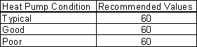
This numeric field contains the fraction of on-cycle power use to adjust the part load fraction based on the off-cycle power consumption due to crankcase heaters, controls, fans, and etc. Suggested value values are below (Henderson et al. 1999):
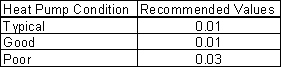
This numeric field contains the time delay in seconds for the heat pump supply air fan to shut off after compressor cycle off. This value can be obtained from the manufacturer or the heat pump catalog. Suggested value is 60 seconds. This value is disregared at times when the WaterToAirHeatPump’s fan operating mode schedule value is greater than 0 (i.e., continuous fan mode).
Enter the name of an HVACTemplate:System:DedicatedOutdoorAir object if this zone is served by a dedicated outdoor air system (DOAS). When a Dedicated Outdoor Air System Name is entered, the outdoor air flow rate for this zone equipment object will be set to zero and the DOAS will provide the ventilation air to the zone based on the outdoor air specifications in this object. If this field is blank, then this zone will not be served by a DOAS.
As shown in an IDF:
HVACTemplate:Zone:WaterToAirHeatPump,
SPACE1-1, !- Zone Name
All Zones, !- Template Thermostat Name
autosize, !- Cooling Supply Air Flow Rate {m3/s}
autosize, !- Heating Supply Air Flow Rate {m3/s}
, !- No Load Supply Air Flow Rate {m3/s}
, !- Zone Heating Sizing Factor
, !- Zone Cooling Sizing Factor
Flow/Person, !- Outdoor Air Method
0.00944, !- Outdoor Air Flow Rate per Person {m3/s}
, !- Outdoor Air Flow Rate per Zone Floor Area {m3/s-m2}
, !- Outdoor Air Flow Rate per Zone {m3/s}
, !- System Availability Schedule Name
Cycling, !- Supply Fan Operating Mode Schedule Name
DrawThrough, !- Supply Fan Placement
0.7, !- Supply Fan Total Efficiency
75, !- Supply Fan Delta Pressure {Pa}
0.9, !- Supply Fan Motor Efficiency
Coil:Cooling:WaterToAirHeatPump:EquationFit, !- Cooling Coil Type
autosize, !- Cooling Coil Rated Capacity {W}
autosize, !- Cooling Coil Rated Sensible Heat Ratio
3, !- Cooling Coil Rated COP
Coil:Heating:WaterToAirHeatPump:EquationFit, !- HPump Heating Coil Type
autosize, !- Heat Pump Heating Coil Rated Capacity {W}
2.75, !- Heat Pump Heating Coil Rated COP
, !- Supplemental Heating Coil Availability Schedule Name
autosize, !- Supplemental Heating Coil Capacity {W}
2.5, !- Maximum Cycling Rate {cycles/hr}
60, !- Heat Pump Time Constant {s}
0.01, !- Fraction of On-Cycle Power Use
60, !- Heat Pump Fan Delay Time {s}
; !- Dedicated Outdoor Air System Name
This object simulates the system portion of a constant volume direct-expansion based HVAC configuration with several different heating options. Often a single HVACTemplate:Zone:Unitary object will be used with a single HVACTemplate:System:Unitary object to simulate single zone direct-expansion based air conditioning systems. In addition, multiple HVACTemplate:Zone:Unitary objects may appear that all reference the same HVACTemplate:System:Unitary object in a multiple zone version. For a multizone system, only one zone is specified as the control zone. Direct expansion includes single packaged rooftop systems commonly seen in commercial buildings and split systems commonly seen in residential buildings.
Enter a name for the HVACTemplate:System:Unitary object. This name is used in the HVACTemplate:Zone:Unitary object to reference this system.
Leave this field blank if you want the system to be available for the entire year to perform heating or cooling if called for by the thermostat. If a schedule name is specified, those times that the system is available should be specified as 1.0. Those times that the system is not available should have a zero value in the schedule specified. If the "Supply Fan Operating Mode" (see below) is set to Cycling, then this is the supply fan operating schedule. If the fan mode is Cycling this is not a schedule of when the system is providing heating, cooling or air flow but a schedule of when it can provide either heating, cooling, or air flow.
Enter the name of the HVACTemplate:Zone:Unitary object that contains the thermostat. While multiple HVACTemplate:Zone:Unitary objects can be part of a HVACTemplate:System:Unitary system, only one of the zones contains a thermostat that controls heating and cooling operation. For a single zone system, this field should contain the name of that zone.
Enter Autosize to set the system maximum air-flow rate to the sum of the zone air flow rates. If a value is entered here for the maximum air-flow rate, it is the upper limit on system flow, even if the zone level air flow inputs sum to a greater value. This flow rate will not be multiplied by a sizing factor or by zone multipliers. If using zone multipliers a value entered here must be large enough to serve the multiplied zones. The units are m3/s.
This field specifies the name of the supply air fan operating mode schedule. The supply air fan operating mode may vary during the simulation based on time-of-day or with a change of season. Schedule values of 0 denote that the supply air fan and the heating or cooling coil cycle on and off together to meet the heating or cooling load (a.k.a. AUTO fan). Schedule values other than 0 denote that the supply fan runs continuously while the heating or cooling coil cycles to meet the load. The keywords Cycling or Continuous may also be used to, specify a single mode of operation for the entire simulation. The default is Cycling.
Enter the total efficiency of the supply fan. This is the ratio of the power delivered to the air to the electrical input power at maximum flow. This is also the product of the fan motor efficiency and fan (impeller) efficiency. The motor efficiency is the power delivered to the shaft divided by the electrical power input to the motor. The fan efficiency is the power delivered to the air divided by the shaft power. The power delivered to the fluid is the mass flow rate of the air multiplied by the pressure rise divided by the air density. Must be greater than 0 and less than or equal to 1.
Enter the pressure rise in Pa at full flow and standard conditions. Standard conditions are considered 20o C at sea level, 101325 Pa.
Enter the shaft power of the supply fan divided by the electrical power consumed. Must be greater than 0 and less than or equal to 1.
Enter the fraction of the motor heat that is added to the air stream. A value of 0 means that the motor is completely outside the air stream. A value of 1 means that all of the motor heat will go into the air stream and act to cause a temperature rise. Must be between 0 and 1.
Enter the type of cooling coil. The choices for this field are:
· None
· SingleSpeedDX
Set this value to “SingleSpeedDX” if you want to simulate a system that provides cooling. You may set this value to “None” if no cooling is desired. The default value is SingleSpeedDX. Future versions may have additional cooling coil types.
Usually set to blank, which allows the cooling coil to be available anytime the system is operating. If a schedule name is specified, it defines when the coil is available. This is most often used when cooling is only available seasonally. A schedule value of 1.0 indicates that the cooling coil can be on during a given time period. A value of zero denotes that the cooling coil cannot be used during that time period.
Enter the cooling supply air temperature in °C to be used for sizing the cooling coil and zone supply air flow rates. The default is 12.8°C.
Enter autosize to let the automatic sizing algorithm determine the cooling coil capacity based on the maximum cooling loads during the cooling design day. If a value is entered, it represents the full load cooling capacity, including both sensible and latent capacity, in watts of the DX coil unit at rated conditions. Rated conditions are air entering the cooling coil at the maximum supply air flow rate at 26.7°C drybulb/19.4°C wetbulb with air entering the outdoor condenser coil at 35°C drybulb. Capacity should be the “gross” capacity where the impact of supply air fan heat is NOT included. The units are in W.
Enter Autosize to allow the sizing algorithm to determine the sensible heat ratio based on the rated capacity and air flow rate. Otherwise, enter the value of the ratio of the sensible capacity divided by total cooling capacity of the DX cooling coil at rated conditions. Rated conditions are air entering the cooling coil at the maximum supply air flow rate at 26.7°C drybulb/19.4°C wetbulb with air entering the outdoor condenser coil at 35°C drybulb. Both the sensible and total cooling capacities used to define the Rated Sensible Heat Ratio (SHR) should be “gross” capacity where the impact of supply air fan heat is NOT included.
Enter the coefficient of performance defined as the gross cooling coil capacity in watts divided by electrical power input in watts of the DX cooling coil unit at rated conditions. Rated conditions are air entering the cooling coil at the maximum supply air flow rate at 26.7°C drybulb/19.4°C wetbulb with air entering the outdoor condenser coil at 35°C drybulb. The input power includes electric power for the compressor and condenser fan but does not include the power consumption of the supply air fan.
Enter the type of heating used in the unitary system. The choices for this field are
· Electric
· Gas
Usually set to blank, which allows the heating coil to be available anytime the system is operating. If a schedule name is specified, it defines when the coil is available. This is most often used when heating is only available seasonally. The schedule values denote whether the heating coil can run during a given time period. A schedule value of 1.0 indicates that the heating coil can be on during a given time period. A value of zero denotes that the heating coil cannot be used during that time period
Enter the heating supply air temperature in °C to be used for sizing the heating coil and zone supply air flow rates. The default is 50°C.
Enter autosize to allow the sizing algorithm to determine the proper capacity required based on the loads experienced during the heating design day. If a value is specified, it is the maximum amount of heat that the coil can deliver in Watts.
Enter gas burner efficiency as a decimal, not as a percent. A burner that is 80% efficient would have an entry of 0.8 here, which is the default
Enter the parasitic electric load associated with the gas heating coil operation, such as a combustion fan. The units are in W.
Enter autosize or a value for the maximum amount of outdoor air flow into the unit when the economizer is operating. Autosize means that 100% of the full supply flow may be taken from outdoor air. If a value is entered, it is used instead of the autosize value. The units are in m3/s. That is, the entered value is used to define the Maximum Outdoor Air Flow Rate for the Controller:OutdoorAir object that will be generated by this template.
Enter autosize or the value for the minimum amount of outdoor air that can enter the unit and be distributed to the zones. Usually this is set to autosize and the value is calculated by the outdoor air requirements of each zone. If a value is entered it overrides the outdoor air specification from the zone level. The units are in m3/s. Note if heat recovery is specified (see Heat Recovery Type below), then a value must be entered in this field, because heat recovery equipment is not yet autosizable. That is, the entered value is used to define the Minimum Outdoor Air Flow Rate for the Controller:OutdoorAir object that will be generated by this template.
Leave this field blank if you want the minimum outdoor air to be the same for all hours in the entire year. If a schedule name is specified, values are decimal fractions (0.0 – 1.0) that multiply the minimum outdoor air flow rate. This schedule is useful for reducing the outdoor air flow rate to zero during unoccupied or start up hours.
The options for this field are
n ‘FixedDryBulb’
n ‘DifferentialDryBulb’
n ‘FixedEnthalpy’
n ‘ DifferentialEnthalpy’
n ‘ElectronicEnthalpy’ (i.e., humidity ratio curve strategy)
n ‘FixedDewPointAndDryBulb’
n ‘DifferentialDryBulbAndEnthalpy’
n ‘NoEconomizer’
Choosing NoEconomizer means the economizer will not operate and the outdoor airflow rate will be at the minimum for the entire simulation.
Choosing FixedDryBulb means the economizer will set the outdoor airflow rate at minimum if the outdoor air temperature is higher than a specified dry-bulb temperature limit.
Choosing DifferentialDryBulb will trigger the outdoor airflow to minimum when the dry-bulb temperature of outdoor air is higher than the dry-bulb temperature of the return air.
FixedEnthalpy checks the upper limit of the enthalpy given as a field input against the enthalpy content of outdoor air and will set the outdoor airflow rate to minimum if the latter is greater than the former.
DifferentialEnthalpy does the same thing but compares the return air enthalpy with the enthalpy of outdoor air. When the enthalpy of outdoor air is greater than the enthalpy of the return air, the outdoor air flow rate is set to minimum.
Choosing ElectronicEnthalpy enables the simulation to calculate the humidity ratio limit of outdoor air based on the dry-bulb temperature of outdoor air and a quadratic/cubic curve, and compare it to the actual outdoor air humidity ratio. If the actual outdoor humidity ratio is greater than the calculated humidity ratio limit, then the outdoor airflow rate is set to minimum.
Choosing FixedDewPointAndDryBulb compares both the outdoor dewpoint temperature and the outdoor dry-bulb temperature to their specified high limit values. If either outdoor temperature exceeds the high limit value, the outdoor airflow rate is set to minimum.
Another option DifferentialDryBulbAndEnthalpy enables the control strategy to be based on both the DifferentialDryBulb and DifferentialEnthalpy economizer control strategies.
In addition to all economizer control types listed above, each control type checks for user-entered values for the upper limit of dry-bulb temperature, enthalpy limit, humidity ratio limit and dewpoint limit. The outdoor air flow rate is set to minimum if any of these entered limits are exceeded.
The default for this field is NoEconomizer.
Enter one of the following choices for this field:
· NoLockout
· LockoutWithHeating
· LockoutWithCompressor
The default value is NoLockout. The LockoutWithHeating means that if the packaged unit is in heating mode, the economizer is locked out – i.e., the economizer dampers are closed and there is minimum outdoor air flow. LockoutWithCompressor means that in addition to locking out the economizer when the unit is in heating mode the economizer is locked out when the DX unit compressor is on. In other words, when the DX coil is off, the economizer must meet the entire cooling load – it isn’t allowed to operate in conjunction with the DX cooling coil. Similarly, when the DX coil is operating, the economizer is not allowed to operate. The LockoutWithCompressor option is sometimes called a “nonintegrated” economizer.
Enter the outdoor air temperature high limit (oC) for economizer operation. If the outdoor air temperature is above this limit, the outdoor air flow rate will be set to the minimum and heat recovery will be enabled if available. No input or zero in this field means that there is no outdoor air temperature high limit control.
Enter the outdoor air temperature low limit (oC) for economizer operation. If the outdoor air temperature is below this limit, the outdoor air flow rate will be set to the minimum and heat recovery will be enabled if available. No input or zero in this field means that there is no outdoor air temperature low limit control.
Enter the outdoor air upper enthalpy limit (in J/kg) for economizer operation. If the outdoor air enthalpy is above this value, the outdoor air flow rate will be set to the minimum and heat recovery will be enabled if available. No input or zero in this field means that there is no outdoor air enthalpy limit control.
Input for this field is the outdoor air dewpoint limit (ºC) for economizer operation. If the outdoor air dewpoint temperature is above this value, the outdoor airflow rate will be set to the minimum. This field is required if the Economizer Control Type ‘FixedDewPointAndDryBulb’ has been specified. No input (blank) in this field means that there is no outdoor air dewpoint limit control.
Set to blank if no supply plenum is to be modeled. If a supply plenum is modeled, it must be modeled as a zone with surfaces, and the name of the plenum zone should be entered here. This supply plenum serves all zones on this system. If any AirLoopHVAC:SupplyPlenums have been specified, the outlet from the system supply plenum will flow through the AirLoopHVAC:SupplyPlenum to the zone terminal unit.
Set to blank if no return plenum is to be modeled. If a return plenum is modeled, it must be modeled as a zone with surfaces, and the name of the plenum zone should be entered here. This return plenum serves all zones on this system. If any zone return plenums have been specified, the return air from the zone will flow through the zone return plenum and then into the system return plenum.
Enter the supply fan placement type. This alpha field has two choices, DrawThrough or BlowThrough. DrawThrough models a system where the supply air fan is after the cooling and heating coils. BlowThrough models a system where the supply air fan is before the cooling and heating coils. The default is BlowThrough.
Enter the system behavior during times when the System Availability Schedule is zero (off). The possible inputs are StayOff, CycleOnAny, or CycleOnControlZone. StayOff means the system will remain off, no matter how hot or cold the zones may be. CycleOnAny means that if any zone served by this system has an air temperature outside the cooling or heating set points the central fan will turn on even though the System Availability Schedule indicates the fan is off. CycleOnControlZone means the same thing except the availability manager looks at the temperature in only the zone specified in Night Cycle Control Zone Name. The default is StayOff.
For the Night Cycle Control option CycleOnControlZone enter the name of the control zone. For other Night Cycle Control options, this field is ignored.
Enter the type of air-to-air heat recovery which is available between the relief air stream and the outdoor air inlet stream. The choices are:
· None
· Sensible
· Enthalpy
The default is None. If heat recovery is specified (i.e., Sensible or Enthalpy), then a value must be entered in the Minimum Outdoor Air Flow Rate field, because heat recovery equipment is not yet autosizable. The entered Minimum Outdoor Air Flow Rate is used to define the Nominal Supply Air Flow Rate for the HeatExchanger:AirToAir:SensibleAndLatent object generated by this template.
Enter the sensible heat recovery effectiveness. This is applied as a constant effectiveness at all conditions. The valid range is from 0.0 to 1.0, and the default is 0.70.
Enter the latent heat recovery effectiveness if Heat Recovery Type is Enthalpy. This is applied as a constant effectiveness at all conditions. The valid range is from 0.0 to 1.0, and the default is 0.65.
There are three dehumidification control type options available:
· None
· CoolReheatHeatingCoil
· CoolReheatDesuperheater
The CoolReheatHeatingCoil option cools beyond the dry-bulb setpoint as required to meet the humidity setpoint if the system is capable of doing so. Reheat is provided as required by the heating coil. In the simulation, two instances of the heating coil are modeled, one for heating, and one for reheat. The two coil objects represent the same physical coil and never operate simultaneously.
The CollReheatDesuperheater option cools beyond the dry-bulb setpoint as required to meet the humidity setpoint if the system is capable of doing so. Reheat is provided by a desuperheater coil (see object Coil:WaterHeating:Desuperheater).
The default is None which meets the sensible cooling load only. The humidistat is located in the same zone that is specified above as the Control Zone or Thermostat Location Name.
This field is deprecated and will be removed. The humidistat is located in the same zone that is specified above as the Control Zone or Thermostat Location Name.
This field specifies the zone humidistat setpoint for dehumidification in percent (0 to 100). The default is 60%.
There are two humidifier type options available:
· None
· ElectricSteam
The ElectricSteam humidifier option uses the Humidifier:Steam:Electric object. The default is None.
If left blank, the humidifier will be available anytime the system is operating. If a schedule name is specified, it defines when the humidifier is available. The schedule values denote whether the humidifier can run during a given time period. A schedule value of 1.0 indicates that the humidifier can be on during a given time period. A value of zero denotes that the humidifier cannot be used during that time period
Enter the rated moisture output rate in m3/s. The humidifier does not currently autosize, so the default is very large to allow for adequate capacity. The default is 0.000001 m3/s.
Enter the electric power input at the rated capacity moisture output. The humidifier does not currently autosize, so the default power input is consistent with the default capacity input (2690 W per 0.000001 m3/s output) Power consumption is proportional to moisture output with no part-load penalty.
This field specifies the zone name where the humidistat is located for controlling humidification.
This field specifies the zone humidistat setpoint for humidification in percent (0 to 100). The default is 30%.
As shown in an IDF:
HVACTemplate:System:Unitary,
AHU 1, !- Air Handling System Name
FanAndCoilAvailSched, !- System Availability Schedule
EAST ZONE, !- Control Zone Name or Thermostat Location
autosize, !- Supply Fan Max Flow Rate {m3/s}
Fan Mode Schedule, !- Supply Fan Operating Mode Schedule
.7, !- Supply Fan Total Efficiency
600, !- Supply Fan Delta Pressure {Pa}
.9, !- Supply Fan Motor Efficiency
1, !- Supply Fan Motor in Air Stream Fraction
SingleSspeedDX, !- Cooling Coil Type
FanAndCoilAvailSched, !- Cooling Coil Availability Schedule
14.0, !- Cooling Design Supply Air Temperature {C}
autosize, !- Cooling Coil Capacity {W}
autosize, !- Cooling Coil Rated SHR
3, !- Cooling Coil Rated COP
Gas, !- Heating Coil Type
FanAndCoilAvailSched, !- Heating Coil Availability Schedule
50.0, !- Heating Design Supply Air Temperature {C}
autosize, !- Heating Coil Capacity {W}
.8, !- Gas Heating Coil Efficiency
0, !- Gas Heating Coil Parasitic Electric Load {W}
autosize, !- Maximum Outdoor air Flow Rate {m3/s}
autosize, !- Minimum Outdoor air Flow Rate {m3/s}
, !- Minimum Outdoor air Schedule Name
NoEconomizer, !- Economizer Type
NoLockout, !- Economizer Lockout
, !- Economizer Upper Temperature Limit {C}
, !- Economizer Lower Temperature Limit {C}
, !- Economizer Upper Enthalpy Limit {J/kg}
, !- Economizer Maximum Limit Dewpoint Temperature {C}
, !- Supply Plenum Name
, !- Return Plenum Name
BlowThrough, !- Supply Fan Placement
CycleOnAny, !- Night Cycle Control
, !- Night Cycle Control Zone Name
None, !- Heat Recovery Type
, !- Sensible Heat Recovery Effectiveness
, !- Latent Heat Recovery Effectiveness
None, !- Dehumidification Control Type
, !- Dehumidification Control Zone Name
60, !- Dehumidification Setpoint {percent}
ElectricSteam, !- Humidifier Type
, !- Humidifier Availability Schedule
0.000001, !- Humidifier Rated Capacity {m3/s}
2690, !- Humidifier Rated Electric Power {W}
EAST ZONE, !- Humidifier Control Zone Name
30; !- Humidifier Setpoint {percent}
This object simulates the system portion of an air to air direct-expansion unitary heat pump. Often a single HVACTemplate:Zone:Unitary object will be used with a single HVACTemplate:System:UnitaryHeatPump:AirToAir object to simulate single zone direct-expansion based heat pump systems. In addition, multiple HVACTemplate:Zone:Unitary objects may appear that all reference the same HVACTemplate:System:UnitaryHeatPump:AirToAir object in a multiple zone version. For a multizone system, only one zone is specified as the control zone. The model can simulate heat pumps seen in commercial buildings and split systems commonly seen in residential buildings.
Enter a name for the HVACTemplate:System:UnitaryHeatPump:AirToAir object. This name is used in the HVACTemplate:Zone:Unitary object to reference this system.
Leave this field blank if you want the system to be available for the entire year to perform heating or cooling if called for by the thermostat. If a schedule name is specified, those times that the system is available should be specified as 1.0. Those times that the system is not available should have a zero value in the schedule specified. During times when the system is available, the supply fan operating mode controls fan operation. (See "Supply Fan Operating Mode Schedule Name" below)
Enter the name of the HVACTemplate:Zone:Unitary object that contains the thermostat. While multiple HVACTemplate:Zone:Unitary objects can be part of a HVACTemplate:System:UnitaryHeatPump:AirToAir system, only one of the zones contains a thermostat that controls heating and cooling operation. For a single zone system, this field should contain the name of that zone.
This field specifies the supply air flow rate when the DX cooling coil is operating. By entering Autosize, the supply air flow rate is automatically determined based on the loads experienced by the zone during the specified cooling SizingPeriod:DesignDay. This flow rate will not be multiplied by a sizing factor or by zone multipliers. If using zone multipliers a value entered here must be large enough to serve the multiplied zones. The units are in m3/s. The default is Autosize.
This field specifies the supply air flow rate when the heating coil is operating. By entering Autosize, the supply air flow rate is automatically determined based on the loads experienced by the zone during the specified heating SizingPeriod:DesignDay. This flow rate will not be multiplied by a sizing factor or by zone multipliers. If using zone multipliers a value entered here must be large enough to serve the multiplied zones. The units are in m3/s. The default is Autosize.
This field specifies the supply air flow rate when neither cooling nor heating is required (i.e., DX coil and heater are off but the supply air fan operates). This field is only used when the supply air fan operating mode schedule specifies continuous fan operation. Values must be greater than or equal to zero, or this field is autosizable. If the air conditioner’s supply air fan operating mode schedule specifies continuous fan operation and this value is set to zero or this field is left blank, then the model assumes that the supply air flow rate when no cooling/heating is needed is equal to the supply air flow rate when the cooling or heating coil was last operating (for cooling operation or heating operation). By entering Autosize, the supply air flow rate will be sized to match the smaller of the Cooling and Heating flow rates. A value entered in this field will not be multiplied by the sizing factor or by zone multipliers. It is best to autosize or leave blank when using zone multipliers. The units are in m3/s. The default is Autosize.
This field specifies the name of the supply air fan operating mode schedule. The supply air fan operating mode may vary during the simulation based on time-of-day or with a change of season. Schedule values of 0 denote that the supply air fan and the heating or cooling coil cycle on and off together to meet the heating or cooling load (a.k.a. AUTO fan). Schedule values other than 0 denote that the supply fan runs continuously while the heating or cooling coil cycles to meet the load. The keywords Cycling or Continuous may also be used to, specify a single mode of operation for the entire simulation. The default is Cycling.
Enter the supply fan placement type. This alpha field has two choices, DrawThrough or BlowThrough. DrawThrough models a system where the supply air fan is after the dx cooling/heating coil and before the supplemental heating coil. BlowThrough models a system where the supply air fan is before the dx cooling/heating coil and the supplemental heating coil. The default is BlowThrough.
Enter the total efficiency of the supply fan. This is the ratio of the power delivered to the air to the electrical input power at maximum flow. This is also the product of the fan motor efficiency and fan (impeller) efficiency. The motor efficiency is the power delivered to the shaft divided by the electrical power input to the motor. The fan efficiency is the power delivered to the air divided by the shaft power. The power delivered to the fluid is the mass flow rate of the air multiplied by the pressure rise divided by the air density. Must be greater than 0 and less than or equal to 1. The default is 0.7.
Enter the pressure rise in Pa at full flow and standard conditions. Standard conditions are considered 20 C at sea level, 101325 Pa. The default is 600 Pa.
Enter the shaft power of the supply fan divided by the electrical power consumed. Must be greater or equal to the Supply Fan Total Efficiency and less than or equal to 1. The default is 0.9.
Enter the fraction of the motor heat that is added to the air stream. A value of 0 means that the motor is completely outside the air stream. A value of 1 means that all of the motor heat will go into the air stream and act to cause a temperature rise. Must be between 0 and 1. The default is 1.0.
Enter the type of cooling coil. There is currently only one choices for this field,
SingleSpeedDX. Future versions may have additional cooling coil types.
Usually set to blank, which allows the cooling coil to be available anytime the system is operating. If a schedule name is specified, it defines when the coil is available. This is most often used when cooling is only available seasonally. A schedule value of 1.0 indicates that the cooling coil can be on during a given time period. A value of zero denotes that the cooling coil cannot be used during that time period.
Enter the cooling supply air temperature in °C to be used for sizing the cooling coil and zone supply air flow rates. The default is 12.8°C.
Enter Autosize to let the automatic sizing algorithm determine the cooling coil capacity based on the maximum cooling loads during the cooling design day. If a value is entered, it represents the full load cooling capacity, including both sensible and latent capacity, in watts of the DX coil unit at rated conditions. Rated conditions are air entering the cooling coil at the maximum supply air flow rate at 26.7°C drybulb/19.4°C wetbulb with air entering the outdoor condenser coil at 35°C drybulb. Capacity should be the “gross” capacity where the impact of supply air fan heat is NOT included. The units are in W. The default is Autosize.
Enter Autosize to allow the sizing algorithm to determine the sensible heat ratio based on the rated capacity and air flow rate. Otherwise, enter the value of the ratio of the sensible capacity divided by total cooling capacity of the DX cooling coil at rated conditions. Rated conditions are air entering the cooling coil at the maximum supply air flow rate at 26.7°C drybulb/19.4°C wetbulb with air entering the outdoor condenser coil at 35°C drybulb. Both the sensible and total cooling capacities used to define the Rated Sensible Heat Ratio (SHR) should be “gross” capacity where the impact of supply air fan heat is NOT included. The default is Autosize.
Enter the coefficient of performance defined as the gross cooling coil capacity in watts divided by electrical power input in watts of the DX cooling coil unit at rated conditions. Rated conditions are air entering the cooling coil at the maximum supply air flow rate at 26.7°C drybulb/19.4°C wetbulb with air entering the outdoor condenser coil at 35°C drybulb. The input power includes electric power for the compressor and condenser fan but does not include the power consumption of the supply air fan. The default is 3.0.
Enter the type of heat pump heating coil. There is currently only one choice for this field, SingleSpeedDXHeatPump.
Enter the heating supply air temperature in °C to be used for sizing the heating coil and zone supply air flow rates. The default is 50°C.
Usually set to blank, which allows the heat pump heating coil to be available anytime the system is operating. If a schedule name is specified, it defines when the coil is available. This is most often used when heating is only available seasonally. A schedule value of 1.0 indicates that the heat pump heating coil can be on during a given time period. A value of zero denotes that the heat pump heating coil cannot be used during that time period.
Enter Autosize to let the automatic sizing algorithm determine the heat pump heating coil capacity based on the maximum heating loads during the heating design day. If a value is entered, it represents the full load heating capacity, in watts of the DX heat pump unit at rated conditions. Rated conditions are air entering the heat pump heating coil at the heating supply air flow rate at 21.11°C drybulb/15.55°C wetbulb with air entering the outdoor coil at 8.33°C drybulb/6.11C wetbulb. Capacity should be the “gross” capacity where the impact of supply air fan heat is NOT included. The units are in W. The default is Autosize.
Enter the coefficient of performance defined as the gross heating coil capacity in watts divided by electrical power input in watts of the DX heating coil unit at rated conditions. Rated conditions are air entering the heat pump heating coil at the heating supply air flow rate at 21.11°C drybulb/15.55°C wetbulb with air entering the outdoor coil at 8.33°C drybulb/6.11C wetbulb. The input power includes electric power for the compressor and condenser fan but does not include the power consumption of the supply air fan. The default is 2.75.
This numeric field defines the minimum outdoor dry-bulb temperature in degrees Celsius for compressor operation. The compressor will not operate (for DX heating or DX cooling) when outdoor dry-bulb temperatures fall below this value. The minimum value must be greater than or equal to -20 °C. The default value is -8°C.
This numeric field defines the outdoor air dry-bulb temperature above which outdoor coil defrosting is disabled. The temperature for this input field must be greater than or equal to 0 C and less than or equal to 7.22 C. If this input field is left blank, the default value is 5 C.
This alpha field has two choices: ReverseCycle or Resistive. If the ReverseCycle strategy is selected, the heating cycle is reversed periodically to provide heat to melt frost accumulated on the outdoor coil. If a Resistive defrost strategy is selected, the frost is melted using an electric resistance heater. If this input field is left blank, the default defrost strategy is ReverseCycle.
This alpha field has two choices: Timed or OnDemand. If Timed control is selected, the defrost time period is calculated based on a fixed value or compressor runtime whether or not frost has actually accumulated. For Timed defrost control, the fractional amount of time the unit is in defrost is entered in the input field “Defrost Time Period Fraction” described below. If OnDemand defrost control is selected, the defrost time period is calculated based on outdoor weather (humidity ratio) conditions. Regardless of which defrost control is selected, defrost does not occur above the user specified outdoor temperature entered in the input field “Heat Pump Defrost Maximum Outdoor Dry-Bulb Temperature” described above. If this input field is left blank, the default defrost control is Timed.
This numeric field defines the fraction of compressor runtime when the defrost cycle is active, and only applies to “timed” defrost (see Heat Pump Defrost Control input field above). For example, if the defrost cycle is active for 3.5 minutes for every 60 minutes of compressor runtime, then the user should enter 3.5/60 = 0.058333. The value for this input field must be greater than or equal to 0. If this input field is left blank, the default value is 0.058333.
Enter the type of supplemental heating coil. The choices for this field are
· Electric
· Gas
The default is Electric.
Usually set to blank, which allows the supplemental heating coil to be available anytime the system is operating. If a schedule name is specified, it defines when the coil is available. This is most often used when supplemental heating is only available seasonally. The schedule values denote whether the supplemental heating coil can run during a given time period. A schedule value of 1.0 indicates that the supplemental heating coil can be on during a given time period. A value of zero denotes that the supplemental heating coil cannot be used during that time period
Enter Autosize to allow the sizing algorithm to determine the proper capacity required based on the loads experienced during the heating design day. If a value is specified, it is the maximum amount of heat that the supplemental heating coil can deliver in Watts. The default is Autosize.
This numeric field defines the outdoor air dry-bulb temperature above which the supplemental heating coil is disabled. The temperature for this input field must be less than or equal to 21 C. If this input field is left blank, the default value is 21 C.
Enter supplemental heating coil gas burner efficiency as a decimal, not as a percent. A burner that is 80% efficient would have an entry of 0.8 here, which is the default. This field applies only if the supplemental heating coil type is gas.
Enter the parasitic electric load associated with the gas supplemental heating coil operation, such as a combustion fan. The units are in W. The default is 0.0. This field applies only if the supplemental heating coil type is gas.
Enter Autosize or a value for the maximum amount of outdoor air flow into the unit when the economizer is operating. Autosize means that 100% of the full supply flow may be taken from outdoor air. The units are in m3/s. That is, the entered value is used to define the Maximum Outdoor Air Flow Rate for the Controller:OutdoorAir object that will be generated by this template.
Enter Autosize or the value for the minimum amount of outdoor air that can enter the unit and be distributed to the zones. Usually this is set to autosize and the value is calculated by the outdoor air requirements of each zone. If a value is entered it overrides the outdoor air specification from the zone level. The units are in m3/s. The default is Autosize. Note if heat recovery is specified (see Heat Recovery Type below), then a value must be entered in this field, because heat recovery equipment is not yet autosizable. That is, the entered value is used to define the Minimum Outdoor Air Flow Rate for the Controller:OutdoorAir object that will be generated by this template.
Leave this field blank if you want the minimum outdoor air to be the same for all hours in the entire year. If a schedule name is specified, values are decimal fractions (0.0 – 1.0) that multiply the minimum outdoor air flow rate. This schedule is useful for reducing the outdoor air flow rate during unoccupied or start up hours.
The options for this field are
n ‘FixedDryBulb’
n ‘DifferentialDryBulb’
n ‘FixedEnthalpy’
n ‘DifferentialEnthalpy’
n ‘ElectronicEnthalpy’ (i.e., humidity ratio curve strategy)
n ‘FixedDewPointAndDryBulb’
n ‘DifferentialDryBulbAndEnthalpy’
n ‘NoEconomizer’
Choosing NoEconomizer means the economizer will not operate and the outdoor airflow rate will be at the minimum for the entire simulation.
Choosing FixedDryBulb means the economizer will set the outdoor airflow rate at minimum if the outdoor air temperature is higher than a specified dry-bulb temperature limit.
Choosing DifferentialDryBulb will trigger the outdoor airflow to minimum when the dry-bulb temperature of outdoor air is higher than the dry-bulb temperature of the return air.
FixedEnthalpy checks the upper limit of the enthalpy given as a field input against the enthalpy content of outdoor air and will set the outdoor airflow rate to minimum if the latter is greater than the former.
DifferentialEnthalpy does the same thing but compares the return air enthalpy with the enthalpy of outdoor air. When the enthalpy of outdoor air is greater than the enthalpy of the return air, the outdoor air flow rate is set to minimum.
Choosing ElectronicEnthalpy enables the simulation to calculate the humidity ratio limit of outdoor air based on the dry-bulb temperature of outdoor air and a quadratic/cubic curve, and compare it to the actual outdoor air humidity ratio. If the actual outdoor humidity ratio is greater than the calculated humidity ratio limit, then the outdoor airflow rate is set to minimum.
Choosing FixedDewPointAndDryBulb compares both the outdoor dewpoint temperature and the outdoor dry-bulb temperature to their specified high limit values. If either outdoor temperature exceeds the high limit value, the outdoor airflow rate is set to minimum.
Another option DifferentialDryBulbAndEnthalpy enables the control strategy to be based on both the DifferentialDryBulb and DifferentialEnthalpy economizer control strategies.
In addition to all economizer control types listed above, each control type checks for user-entered values for the upper limit of dry-bulb temperature, enthalpy limit, humidity ratio limit and dewpoint limit. The outdoor air flow rate is set to minimum if any of these entered limits are exceeded.
The default for this field is NoEconomizer
Enter one of the following choices for this field:
· NoLockout
· LockoutWithHeating
· LockoutWithCompressor
The default value is NoLockout. The LockoutWithHeating means that if the packaged unit is in heating mode, the economizer is locked out – i.e., the economizer dampers are closed and there is minimum outdoor air flow. LockoutWithCompressor means that in addition to locking out the economizer when the unit is in heating mode the economizer is locked out when the DX unit compressor is on. In other words, when the DX coil is off, the economizer must meet the entire cooling load – it isn’t allowed to operate in conjunction with the DX cooling coil. Similarly, when the DX coil is operating, the economizer is not allowed to operate. The LockoutWithCompressor option is sometimes called a “nonintegrated” economizer.
Input for this field is the outdoor air temperature high limit (ºC) for economizer operation. If the outdoor air temperature is above this limit, the outdoor airflow rate will be set to the minimum. This field is required if Economizer Control Type ‘FixedDryBulb’ or ‘FixedDewPointAndDryBulb’ has been specified. No input (blank) in this field means that there is no outdoor air temperature high limit control.
Enter the outdoor air upper enthalpy limit (in J/kg) for economizer operation. If the outdoor air enthalpy is above this value, the outdoor air flow rate will be set to the minimum and heat recovery will be enabled if available. No input or zero in this field means that there is no outdoor air enthalpy limit control.
Input for this field is the outdoor air dewpoint limit (ºC) for economizer operation. If the outdoor air dewpoint temperature is above this value, the outdoor airflow rate will be set to the minimum. This field is required if the Economizer Control Type ‘FixedDewPointAndDryBulb’ has been specified. No input (blank) in this field means that there is no outdoor air dewpoint limit control.
Enter the outdoor air temperature low limit (C) for economizer operation. If the outdoor air temperature is below this limit, the outdoor air flow rate will be set to the minimum and heat recovery will be enabled if available. No input or zero in this field means that there is no outdoor air temperature low limit control.
Set to blank if no supply plenum is to be modeled. If a supply plenum is modeled, it must be modeled as a zone with surfaces, and the name of the plenum zone should be entered here. This supply plenum serves all zones on this system. If any zone supply plenums have been specified, the outlet from the system supply plenum will flow through the zone supply plenum to the zone terminal unit.
Set to blank if no return plenum is to be modeled. If a return plenum is modeled, it must be modeled as a zone with surfaces, and the name of the plenum zone should be entered here. This return plenum serves all zones on this system. If any zone return plenums have been specified, the return air from the zone will flow through the zone return plenum and then into the system return plenum.
Enter the system behavior during times when the System Availability Schedule is zero (off). The possible inputs are StayOff, CycleOnAny, or CycleOnControlZone. StayOff means the system will remain off, no matter how hot or cold the zones may be. CycleOnAny means that if any zone served by this system has an air temperature outside the cooling or heating set points the central fan will turn on even though the System Availability Schedule indicates the fan is off. CycleOnControlZone means the same thing except the availability manager looks at the temperature in only the zone specified in Night Cycle Control Zone Name. The default is StayOff.
For the Night Cycle Control option CycleOnControlZone enter the name of the control zone. For other Night Cycle Control options, this field is ignored.
Enter the type of air-to-air heat recovery which is available between the relief air stream and the outdoor air inlet stream. The choices are:
· None
· Sensible
· Enthalpy
The default is None. If heat recovery is specified (i.e., Sensible or Enthalpy), then a value must be entered in the Minimum Outdoor Air Flow Rate field, because heat recovery equipment is not yet autosizable. The entered Minimum Outdoor Air Flow Rate is used to define the Nominal Supply Air Flow Rate for the HeatExchanger:AirToAir:SensibleAndLatent object generated by this template.
Enter the sensible heat recovery effectiveness. This is applied as a constant effectiveness at all conditions. The valid range is from 0.0 to 1.0, and the default is 0.70.
Enter the latent heat recovery effectiveness if Heat Recovery Type is Enthalpy. This is applied as a constant effectiveness at all conditions. The valid range is from 0.0 to 1.0, and the default is 0.65.
There are two humidifier type options available:
· None
· ElectricSteam
The ElectricSteam humidifier option uses the Humidifier:Steam:Electric object. The default is None.
If left blank, the humidifier will be available anytime the system is operating. If a schedule name is specified, it defines when the humidifier is available. The schedule values denote whether the humidifier can run during a given time period. A schedule value of 1.0 indicates that the humidifier can be on during a given time period. A value of zero denotes that the humidifier cannot be used during that time period
Enter the rated moisture output rate in m3/s. The humidifier does not currently autosize, so the default is very large to allow for adequate capacity. The default is 0.000001 m3/s.
Enter the electric power input at the rated capacity moisture output. The humidifier does not currently autosize, so the default power input is consistent with the default capacity input (2690 W per 0.000001 m3/s output) Power consumption is proportional to moisture output with no part-load penalty.
This field specifies the zone name where the humidistat is located for controlling humidification.
This field specifies the zone humidistat setpoint for humidification in percent (0 to 100). The default is 30%.
As shown in an IDF:
HVACTemplate:System:UnitaryHeatPump:AirToAir,
Heat Pump 1, !- Name
FanAvailSched, !- System Availability Schedule Name
SPACE1-1, !- Control Zone or Thermostat Location Name
autosize, !- Cooling Supply Air Flow Rate {m3/s}
autosize, !- Heating Supply Air Flow Rate {m3/s}
autosize, !- No Load Supply Air Flow Rate {m3/s}
Cycling, !- Supply Fan Operating Mode Schedule Name
BlowThrough, !- Supply Fan Placement
0.7, !- Supply Fan Total Efficiency
600, !- Supply Fan Delta Pressure {Pa}
0.9, !- Supply Fan Motor Efficiency
1, !- Supply Fan Motor in Air Stream Fraction
SingleSpeedDX, !- Cooling Coil Type
, !- Cooling Coil Availability Schedule Name
14, !- Cooling Design Supply Air Temperature {C}
autosize, !- Cooling Coil Capacity {W}
autosize, !- Cooling Coil Rated Sensible Heat Ratio
3, !- Cooling Coil Rated COP
SingleSpeedDXHeatPump, !- Heat Pump Heating Coil Type
, !- Heat Pump Heating Coil Availability Schedule Name
50.0, !- Heating Design Supply Air Temperature {C}
autosize, !- Heat Pump Heating Coil Rated Capacity {W}
2.75, !- Heat Pump Heating Coil Rated COP
-8, !- Heat Pump Heating Minimum Outdoor Dry-Bulb Temperature {C}
5, !- Heat Pump Defrost Maximum Outdoor Dry-Bulb Temperature {C}
ReverseCycle, !- Heat Pump Defrost Strategy
Timed, !- Heat Pump Defrost Control
0.058333, !- Heat Pump Defrost Time Period Fraction
Electric, !- Supplemental Heating Coil Type
, !- Supplemental Heating Coil Availability Schedule Name
autosize, !- Supplemental Heating Coil Capacity {W}
21, !- Supplemental Heating Coil Max Outdoor Dry-Bulb Temperature {C}
0.8, !- Supplemental Gas Heating Coil Efficiency
, !- Supplemental Gas Heating Coil Parasitic Electric Load {W}
autosize, !- Maximum Outdoor Air Flow Rate {m3/s}
autosize, !- Minimum Outdoor Air Flow Rate {m3/s}
Min OA Sched, !- Minimum Outdoor Air Schedule Name
DifferentialDryBulb, !- Economizer Type
NoLockout, !- Economizer Lockout
19, !- Economizer Maximum Limit Dry-Bulb Temperature {C}
, !- Economizer Maximum Limit Enthalpy {J/kg}
, !- Economizer Maximum Limit Dewpoint Temperature {C}
4, !- Economizer Minimum Limit Dry-Bulb Temperature {C}
, !- Supply Plenum Name
, !- Return Plenum Name
CycleOnAny, !- Night Cycle Control
, !- Night Cycle Control Zone Name
None, !- Heat Recovery Type
0.7, !- Sensible Heat Recovery Effectiveness
0.65, !- Latent Heat Recovery Effectiveness
None, !- Humidifier Type
, !- Humidifier Availability Schedule Name
0.000001, !- Humidifier Rated Capacity {m3/s}
2690, !- Humidifier Rated Electric Power {W}
, !- Humidifier Control Zone Name
30; !- Humidifier Setpoint {percent}
This object simulates the system portion of a variable air volume HVAC configuration with several different heating options. Multiple HVACTemplate:Zone:VAV objects are usually specified for each HVACTemplate:System:VAV object.
Enter a name for the HVACTemplate:System:VAV object. This name is used in the HVACTemplate:Zone:VAV object to reference this system.
Leave this field blank if you want the system to be available for the entire year to perform heating or cooling if called for by the thermostat. If a schedule name is specified, those times that the system is available should be specified as 1.0. Those times that the system is not available should have a zero value in the schedule specified. Please note that for this system type, this is a schedule of when the system is providing air flow.
Enter Autosize to set the system maximum air-flow rate to the sum of the zone air flow rates. If a value is entered here for the maximum air-flow rate, it is the upper limit on system flow, even if the zone level air flow inputs sum to a greater value. This flow rate will not be multiplied by a sizing factor or by zone multipliers. If using zone multipliers a value entered here must be large enough to serve the multiplied zones. The units are m3/s.
Enter the minimum supply air volume that may be provided. This field may be set to autosize. The units are in m3/s.
Enter the total efficiency of the supply fan. This is the ratio of the power delivered to the air to the electrical input power at maximum flow. This is also the product of the fan motor efficiency and fan (impeller) efficiency. The motor efficiency is the power delivered to the shaft divided by the electrical power input to the motor. The fan efficiency is the power delivered to the air divided by the shaft power. The power delivered to the fluid is the mass flow rate of the air multiplied by the pressure rise divided by the air density. Must be greater than 0 and less than or equal to 1.
Enter the pressure rise in Pa at full flow and standard conditions. Standard conditions are considered 20o C at sea level, 101325 Pa.
Enter the shaft power of the supply fan divided by the electrical power consumed. Must be greater than 0 and less than or equal to 1.
Enter the fraction of the motor heat that is added to the air stream. A value of 0 means that the motor is completely outside the air stream. A value of 1 means that all of the motor heat will go into the air stream and act to cause a temperature rise. Must be between 0 and 1.
There are two coil types available:
· ChilledWater
· ChilledWaterDetailedFlatModel
ChilledWater uses the COIL:Cooling:Water object with the DetailedAnalysis option. This is the preferred coil model for most applications. ChilledWaterDetailedFlatModel uses the Coil:Cooling:Water:DetailedGeometry object. This option is available for special applications. The default is ChilledWater.
Usually set to blank, which allows the cooling coil to be available anytime the system is operating. If a schedule name is specified, it defines when the coil is available. This is most often used when cooling is only available seasonally. A schedule value of one indicates that the cooling coil can be on during a given time period. A value of zero denotes that the cooling coil cannot be used during that time period.
If a constant setpoint for the cooling coil is to be specified, leave this field blank, and the Cooling Coil Design Setpoint value will be used at all times. If a set point schedule is to be used for the cooling coil specify the schedule name here. The schedule should control the supply air temperature delivered to the zones. For Blow Through fan placement, this is the leaving air temperature from the cooling coil. For Draw Through fan placement, this is the leaving air temperature after the supply fan. The values in the schedule are in degrees C. This field is ignored if the Cooling Coil Setpoint Reset Type is something other than None (see below).
Enter the cooling supply air temperature in C to be used for sizing the cooling coil and zone supply air flow rates. The default is 12.8C. If no Cooling Coil Setpoint Schedule or Cooling Coil Setpoint Reset Type is specified, this value is used as a constant cooling supply air setpoint temperature.
The heating coil is located in the supply air stream, upstream of the cooling coil and after the outdoor air mixing box. If no central heating coil is used in the VAV system, then the option “none” should be specified here. Otherwise this indicates the type of heating coil. It is unlikely that both a heating coil and a preheat coil would be used at the same time. The choices for this field are
· HotWater
· Electric
· Gas
· None
The default value is None. Note that the configuration of HVACTemplate:System:VAV assumes that there will be reheat coils or baseboard heating to provide heating control at the zone level. If a heating coil is specified, the heating and cooling coil setpoint controls and availability schedules must coordinate to prevent the coils from opposing each other.
Usually set to blank, which allows the heating coil to be available anytime the system is operating. If a schedule name is specified, it defines when the coil is available. This is most often used when heating is only available seasonally. The schedule values denote whether the heating coil can run during a given time period. A schedule value of one indicates that the heating coil can be on during a given time period. A value of zero denotes that the heating coil cannot be used during that time period
If a constant setpoint for the heating coil is to be specified, leave this field blank, and the Heating Coil Design Setpoint value will be used at all times. If a set point schedule is to be used for the heating coil specify the schedule name here. The schedule should control the supply air temperature delivered to the zones. For Blow Through fan placement, this is the leaving air temperature from the heating coil. For Draw Through fan placement, this is the leaving air temperature after the supply fan. The values in the schedule are in degrees C. This field is ignored if the Heating Coil Setpoint Reset Type is something other than None (see below).
Enter the heating supply air temperature in C to be used for sizing the heating coil and zone supply air flow rates. If no Heating Coil Setpoint Schedule or Heating Coil Setpoint Reset Type is specified, this value is used as a constant heating supply air setpoint temperature. The default is 10.0C.
Enter gas burner efficiency as a decimal, not as a percent. A burner that is 80% efficient would have an entry of 0.8 here, which is the default
Enter the parasitic electric load associated with the gas heating operation, such as a combustion fan. The units are in W.
The preheat coil is located in the outdoor air stream, upstream of the outdoor air mixing box and tempers the outdoor air. If no preheat coil is used in the VAV system, then the option “none” should be specified here. Otherwise this indicates the type of preheat coil. It is unlikely that both a heating coil and a preheat coil would be used at the same time. The choices for this field are
· Electric
· Gas
· None
The default value is None. If a preheat coil is specified, the preheat and cooling coil setpoint controls and availability schedules must coordinate to prevent the coils from opposing each other.
Usually set to blank, which allows the preheat coil to be available anytime the system is operating. If a schedule name is specified, it defines when the preheat coil is available. This is most often used when preheat is only available seasonally. The schedule values denote whether the preheat coil can run during a given time period. A schedule value of 1.0 indicates that the preheat coil can be on during a given time period. A value of zero denotes that the preheat coil cannot be used during that time period
If a constant setpoint for the preheat coil is to be specified, leave this field blank, and the Preheat Coil Design Setpoint value will be used at all times. If a set point schedule is to be used for the preheat coil specify the schedule name here. The schedule should control the leaving air temperature from the preheat coil. The values in the schedule are in degrees C.
Enter the preheat supply air temperature in C to be used for sizing the preheat coil. If no Preheat Coil Setpoint Schedule is specified, this value is used as a constant preheat supply air setpoint temperature. The default is 7.2C.
Enter gas burner efficiency as a decimal, not as a percent. A burner that is 80% efficient would have an entry of 0.8 here, which is the default
Enter the parasitic electric load associated with the gas heating operation, such as an combustion fan. The units are in W.
Enter autosize or a value for the maximum amount of outdoor air flow into the unit when the economizer is operating. Autosize means that 100% of the full supply flow may be taken from outdoor air. If a value is entered, it is used instead of the autosize value. The units are in m3/s. That is, the entered value is used to define the Maximum Outdoor Air Flow Rate for the Controller:OutdoorAir object that will be generated by this template.
Enter autosize or the value for the minimum amount of outdoor air that can enter the unit and be distributed to the zones. Usually this is set to autosize and the value is calculated by the outdoor air requirements of each zone. If a value is entered it overrides the outdoor air specification from the zone level. The units are in m3/s. Note if heat recovery is specified (see Heat Recovery Type below), then a value must be entered in this field, because heat recovery equipment is not yet autosizable. That is, the entered value is used to define the Minimum Outdoor Air Flow Rate for the Controller:OutdoorAir object that will be generated by this template.
Choices for this field are FixedMinimum or ProportionalMinimum. FixedMinimum means that the minimum outdoor air flow rate is fixed no matter what the actual system flow rate is. ProportionalMinimum means the minimum outdoor air flow rate varies in proportion to the total system air flow rate. The default is ProportionalMinimum.
Leave this field blank if you want the minimum outdoor air to be the same for all hours in the entire year. If a schedule name is specified, values are decimal fractions (0.0 – 1.0) that multiply the minimum outdoor air flow rate. This schedule is useful for reducing the outdoor air flow rate to zero during unoccupied or start up hours.
The options for this field are
n ‘FixedDryBulb’
n ‘DifferentialDryBulb’
n ‘FixedEnthalpy’
n ‘ DifferentialEnthalpy’
n ‘ElectronicEnthalpy’ (i.e., humidity ratio curve strategy)
n ‘FixedDewPointAndDryBulb’
n ‘DifferentialDryBulbAndEnthalpy’
n ‘NoEconomizer’
Choosing NoEconomizer means the economizer will not operate and the outdoor airflow rate will be at the minimum for the entire simulation.
Choosing FixedDryBulb means the economizer will set the outdoor airflow rate at minimum if the outdoor air temperature is higher than a specified dry-bulb temperature limit.
Choosing DifferentialDryBulb will trigger the outdoor airflow to minimum when the dry-bulb temperature of outdoor air is higher than the dry-bulb temperature of the return air.
FixedEnthalpy checks the upper limit of the enthalpy given as a field input against the enthalpy content of outdoor air and will set the outdoor airflow rate to minimum if the latter is greater than the former.
DifferentialEnthalpy does the same thing but compares the return air enthalpy with the enthalpy of outdoor air. When the enthalpy of outdoor air is greater than the enthalpy of the return air, the outdoor air flow rate is set to minimum.
Choosing ElectronicEnthalpy enables the simulation to calculate the humidity ratio limit of outdoor air based on the dry-bulb temperature of outdoor air and a quadratic/cubic curve, and compare it to the actual outdoor air humidity ratio. If the actual outdoor humidity ratio is greater than the calculated humidity ratio limit, then the outdoor airflow rate is set to minimum.
Choosing FixedDewPointAndDryBulb compares both the outdoor dewpoint temperature and the outdoor dry-bulb temperature to their specified high limit values. If either outdoor temperature exceeds the high limit value, the outdoor airflow rate is set to minimum.
Another option DifferentialDryBulbAndEnthalpy enables the control strategy to be based on both the DifferentialDryBulb and DifferentialEnthalpy economizer control strategies.
In addition to all economizer control types listed above, each control type checks for user-entered values for the upper limit of dry-bulb temperature, enthalpy limit, humidity ratio limit and dewpoint limit. The outdoor air flow rate is set to minimum if any of these entered limits are exceeded.
The default for this field is NoEconomizer.
The only choice for this field is
· NoLockout
The default value is NoLockout. Future versions may have additional options.
Enter the outdoor air temperature high limit (oC) for economizer operation. If the outdoor air temperature is above this limit, the outdoor air flow rate will be set to the minimum and heat recovery will be enabled if available. No input or zero in this field means that there is no outdoor air temperature high limit control.
Enter the outdoor air temperature low limit (oC) for economizer operation. If the outdoor air temperature is below this limit, the outdoor air flow rate will be set to the minimum and heat recovery will be enabled if available. No input or zero in this field means that there is no outdoor air temperature low limit control.
Enter the outdoor air upper enthalpy limit (in J/kg) for economizer operation. If the outdoor air enthalpy is above this value, the outdoor air flow rate will be set to the minimum and heat recovery will be enabled if available. No input or zero in this field means that there is no outdoor air enthalpy limit control.
Input for this field is the outdoor air dewpoint limit (ºC) for economizer operation. If the outdoor air dewpoint temperature is above this value, the outdoor airflow rate will be set to the minimum. This field is required if the Economizer Control Type ‘FixedDewPointAndDryBulb’ has been specified. No input (blank) in this field means that there is no outdoor air dewpoint limit control.
Set to blank if no supply plenum is to be modeled. If a supply plenum is modeled, it must be modeled as a zone with surfaces, and the name of the plenum zone should be entered here. This supply plenum serves all zones on this system. If any AirLoopHVAC:SupplyPlenums have been specified, the outlet from the system supply plenum will flow through the AirLoopHVAC:SupplyPlenum to the zone terminal unit.
Set to blank if no return plenum is to be modeled. If a return plenum is modeled, it must be modeled as a zone with surfaces, and the name of the plenum zone should be entered here. This return plenum serves all zones on this system. If any zone return plenums have been specified, the return air from the zone will flow through the zone return plenum and then into the system return plenum.
Enter the supply fan placement type. This alpha field has two choices, DrawThrough or BlowThrough. DrawThrough models a system where the supply air fan is after the cooling and heating coils. BlowThrough models a system where the supply air fan is before the cooling and heating coils. The default is Draw Through.
Select the set of generic pre-defined coefficients to use for the supply fan part-load power consumption. This alpha field has the following choices:
· InletVaneDampers
· OutletDampers
· VariableSpeedMotor
· ASHRAE90.1-2004Appendix G
· VariableSpeedMotorPressureReset
The default is InletVaneDampers. The resulting power curves are shown in Figure 140. VAV Supply Fan Part-Load Power Coefficient Options below. The ASHRAE 90.1-2004 Appendix G coefficients are from TABLE G3.1.3.15, Method 2. The other sets of coefficients are from the EnergyPlus Input Output Reference, Fan Coefficient Values table. The VariableSpeedMotorPressureReset option is based on Good Static Pressure Reset VSD Fan from Energy Design Resources’: Design Guidelines: Advanced Variable Air Volume (VAV) Systems (EDR_DesignGuidelines_VAV.pdf).
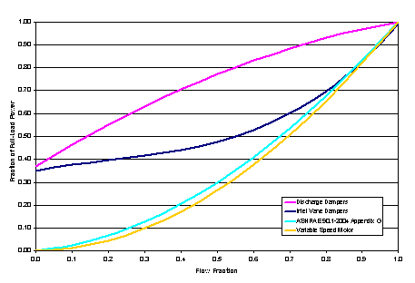
Figure 140. VAV Supply Fan Part-Load Power Coefficient Options
Enter the system behavior during times when the System Availability Schedule is zero (off). The possible inputs are StayOff, CycleOnAny, CycleOnControl Zone or CycleOnAnyZoneFansOnly. StayOff means the system will remain off, no matter how hot or cold the zones may be. CycleOnAny means that if any zone served by this system has an air temperature outside the cooling or heating set points the central fan will turn on even though the System Availability Schedule indicates the fan is off. CycleOnControlZone means the same thing except the availability manager looks at the temperature in only the zone specified in Night Cycle Control Zone Name. CycleOnAnyZoneFansOnly is the same as CycleOnAny except that only the zone fans are cycled on and the central air handler fan is left off (applicable only if using HVACTemplate:Zone:VAV:FanPowered in one or more zones). The default is StayOff.
For the Night Cycle Control option Cycle On Control Zone enter the name of the control zone. For other Night Cycle Control options, this field is ignored.
Enter the type of air-to-air heat recovery which is available between the relief air stream and the outdoor air inlet stream. The choices are:
· None
· Sensible
· Enthalpy
The default is None. If heat recovery is specified (i.e., Sensible or Enthalpy), then a value must be entered in the Minimum Outdoor Air Flow Rate field, because heat recovery equipment is not yet autosizable. The entered Minimum Outdoor Air Flow Rate is used to define the Nominal Supply Air Flow Rate for the HeatExchanger:AirToAir:SensibleAndLatent object generated by this template.
Enter the sensible heat recovery effectiveness. This is applied as a constant effectiveness at all conditions. The valid range is from 0.0 to 1.0, and the default is 0.70.
Enter the latent heat recovery effectiveness if Heat Recovery Type is Enthalpy. This is applied as a constant effectiveness at all conditions. The valid range is from 0.0 to 1.0, and the default is 0.65.
Select the type of automatic reset control for the cooling supply air temperature. The choices are:
· None – no reset, use the Cooling Coil Setpoint Schedule or Cooling Coil Design Setpoint.
· Warmest – reset the cooling supply air temperature to the highest supply air temperature that will meet the cooling requirements of all the zones. The minimum setpoint allowed is the Cooling Coil Design Setpoint. The maximum setpoint allowed is defaulted to 18C. (Reference SetpointManager:Warmest)
· OutdoorAirTemperatureReset – reset the cooling supply air temperature based on the following default rules. When the outdoor dry-bulb temperature (ODB) is at or below 15.6C the setpoint is 18.0C. When the ODB is at or above 26.7C the setpoint is the Cooling Coil Design Setpoint. In between, the setpoint is varied linearly. (Reference SetpointManager:OutdoorAirReset)
The default is None.
Select the type of automatic reset control for the central heating supply air temperature. The choices are:
· None – no reset, use the Heating Coil Setpoint Schedule or Heating Coil Design Setpoint.
· OutdoorAirTemperatureReset – reset the heating supply air temperature based on the following default rules. When the outdoor dry-bulb temperature (ODB) is at or below –6.7C the setpoint is the Heating Coil Design Setpoint. When the ODB is at or above 10.0C the setpoint is 20.0C. In between, the setpoint is varied linearly. (Reference SetpointManager:OutdoorAirReset).
The default is None.
There are two dehumidification control type options available:
· None
· CoolReheat
The CoolReheat option cools beyond the dry-bulb setpoint as required to meet the humidity setpoint if the system is capable of doing so. Reheat is provided as required by the terminal unit reheat coils if available.
The default is None which meets the sensible cooling setpoint only..
This field specifies the zone name where the humidistat is located for controlling dehumidification.
This field specifies the zone humidistat setpoint for dehumidification in percent (0 to 100). The default is 60%.
There are two humidifier type options available:
· None
· ElectricSteam
The ElectricSteam humidifier option uses the Humidifier:Steam:Electric object. The default is None.
If left blank, the humidifier will be available anytime the system is operating. If a schedule name is specified, it defines when the humidifier is available. The schedule values denote whether the humidifier can run during a given time period. A schedule value of 1.0 indicates that the humidifier can be on during a given time period. A value of zero denotes that the humidifier cannot be used during that time period
Enter the rated moisture output rate in m3/s. The humidifier does not currently autosize, so the default is very large to allow for adequate capacity. The default is 0.000001 m3/s.
Enter the electric power input at the rated capacity moisture output. The humidifier does not currently autosize, so the default power input is consistent with the default capacity input (2690 W per 0.000001 m3/s output) Power consumption is proportional to moisture output with no part-load penalty.
This field specifies the zone name where the humidistat is located for controlling humidification.
This field specifies the zone humidistat setpoint for humidification in percent (0 to 100). The default is 30%.
As shown in an IDF:
HVACTemplate:System:VAV,
VAV Sys 1, !- Name
FanAvailSched, !- System Availability Schedule Name
autosize, !- Supply Fan Maximum Flow Rate {m3/s}
autosize, !- Supply Fan Minimum Flow Rate {m3/s}
0.7, !- Supply Fan Total Efficiency
600, !- Supply Fan Delta Pressure {Pa}
0.9, !- Supply Fan Motor Efficiency
1, !- Supply Fan Motor in Air Stream Fraction
ChilledWater, !- Cooling Coil Type
, !- Cooling Coil Availability Schedule Name
, !- Cooling Coil Setpoint Schedule Name
12.8, !- Cooling Coil Design Setpoint {C}
HotWater, !- Heating Coil Type
, !- Heating Coil Availability Schedule Name
, !- Heating Coil Setpoint Schedule Name
10.0, !- Heating Coil Design Setpoint {C}
0.8, !- Gas Heating Coil Efficiency
0.0, !- Gas Heating Coil Parasitic Electric Load {W}
None, !- Preheat Coil Type
, !- Preheat Coil Availability Schedule Name
, !- Preheat Coil Setpoint Schedule Name
, !- Preheat Coil Design Setpoint {C}
0.8, !- Gas Preheat Coil Efficiency
0.0, !- Gas Preheat Coil Parasitic Electric Load {W}
autosize, !- Maximum Outdoor Air Flow Rate {m3/s}
autosize, !- Minimum Outdoor Air Flow Rate {m3/s}
FixedMinimum, !- Minimum Outdoor Air Control Type
Min OA Sched, !- Minimum Outdoor Air Schedule Name
DifferentialDryBulb, !- Economizer Type
NoLockout, !- Economizer Lockout
19, !- Economizer Upper Temperature Limit {C}
4, !- Economizer Lower Temperature Limit {C}
, !- Economizer Upper Enthalpy Limit {J/kg}
, !- Economizer Maximum Limit Dewpoint Temperature {C}
, !- Supply Plenum Name
PLENUM-1, !- Return Plenum Name
DrawThrough, !- Supply Fan Placement
InletVaneDampers, !- Supply Fan Part-Load Power Coefficients
CycleOnAnyZoneFansOnly, !- Night Cycle Control
, !- Night Cycle Control Zone Name
None, !- Heat Recovery Type
0.70, !- Sensible Heat Recovery Effectiveness
0.65, !- Latent Heat Recovery Effectiveness
None, !- Cooling Coil Setpoint Reset Type
None, !- Heating Coil Setpoint Reset Type
None, !- Dehumidification Control Type
, !- Dehumidification Control Zone Name
60.0, !- Dehumidification Setpoint {percent}
None, !- Humidifier Type
, !- Humidifier Availability Schedule Name
0.000001, !- Humidifier Rated Capacity {m3/s}
2690.0, !- Humidifier Rated Electric Power {W}
, !- Humidifier Control Zone Name
30.0; !- Humidifier Setpoint {percent}
This object simulates the system portion of a packaged direct-expansion based variable air volume HVAC configuration with several different heating options. Multiple HVACTemplate:Zone:VAV objects are usually specified for each HVACTemplate:System:PackagedVAV object.
Enter a name for the HVACTemplate:System:PackagedVAV object. This name is used in the HVACTemplate:Zone:VAV object to reference this system.
Leave this field blank if you want the system to be available for the entire year to perform heating or cooling if called for by the thermostat. If a schedule name is specified, those times that the system is available should be specified as 1.0. Those times that the system is not available should have a zero value in the schedule specified. Please note that for this system type, this is a schedule of when the system is providing air flow.
Enter Autosize to set the system maximum air-flow rate to the sum of the zone air flow rates. If a value is entered here for the maximum air-flow rate, it is the upper limit on system flow, even if the zone level air flow inputs sum to a greater value. This flow rate will not be multiplied by a sizing factor or by zone multipliers. If using zone multipliers a value entered here must be large enough to serve the multiplied zones. The units are m3/s. The default is Autosize.
Enter the minimum supply air volume that may be provided. This field may be set to autosize. The units are in m3/s.
Enter the supply fan placement type. This alpha field has two choices, DrawThrough or BlowThrough. DrawThrough models a system where the supply air fan is after the cooling and heating coils. BlowThrough models a system where the supply air fan is before the cooling and heating coils. The default is DrawThrough.
Enter the total efficiency of the supply fan. This is the ratio of the power delivered to the air to the electrical input power at maximum flow. This is also the product of the fan motor efficiency and fan (impeller) efficiency. The motor efficiency is the power delivered to the shaft divided by the electrical power input to the motor. The fan efficiency is the power delivered to the air divided by the shaft power. The power delivered to the fluid is the mass flow rate of the air multiplied by the pressure rise divided by the air density. Must be greater than 0 and less than or equal to 1. The default is 0.7.
Enter the pressure rise in Pa at full flow and standard conditions. Standard conditions are considered 20o C at sea level, 101325 Pa. The default is 1000 Pa.
Enter the shaft power of the supply fan divided by the electrical power consumed. Must be greater or equal to the Supply Fan Total Efficiency and less than or equal to 1. The default is 0.9.
Enter the fraction of the motor heat that is added to the air stream. A value of 0 means that the motor is completely outside the air stream. A value of 1 means that all of the motor heat will go into the air stream and act to cause a temperature rise. Must be between 0 and 1. The default is 1.0.
The coil types available:
· TwoSpeedDX
· TwoSpeedHumidControlDX
TwoSpeedDX uses the Coil:Cooling:DX:TwoSpeed object. This is the preferred coil model for most applications. The TwoSpeedHumidControlDX option uses the Coil:Cooling:DX:TwoStageWithHumidityControlMode object.
Usually set to blank, which allows the cooling coil to be available anytime the system is operating. If a schedule name is specified, it defines when the coil is available. This is most often used when cooling is only available seasonally. A schedule value of one indicates that the cooling coil can be on during a given time period. A value of zero denotes that the cooling coil cannot be used during that time period.
If a constant setpoint for the cooling coil is to be specified, leave this field blank, and the Cooling Coil Design Setpoint value will be used at all times. If a set point schedule is to be used for the cooling coil specify the schedule name here. The schedule should control the supply air temperature delivered to the zones. For Blow Through fan placement, this is the leaving air temperature from the cooling coil. For Draw Through fan placement, this is the leaving air temperature after the supply fan. The values in the schedule are in degrees C. This field is ignored if the Cooling Coil Setpoint Reset Type is something other than None (see below). The default is None.
Enter the cooling supply air temperature in degrees C to be used for sizing the cooling coil and zone supply air flow rates. The default is 12.8C. If no Cooling Coil Setpoint Schedule or Cooling Coil Setpoint Reset Type is specified, this value is used as a constant cooling supply air setpoint temperature.
Enter Autosize to let the automatic sizing algorithm determine the cooling coil capacity based on the maximum cooling loads during the cooling design day. If a value is entered, it represents the full load cooling capacity, including both sensible and latent capacity, in watts of the DX coil unit at rated conditions. Rated conditions are air entering the cooling coil at the maximum supply air flow rate at 26.7°C drybulb/19.4°C wetbulb with air entering the outdoor condenser coil at 35°C drybulb. Capacity should be the “gross” capacity where the impact of supply air fan heat is NOT included. The units are in W. The default is Autosize.
Enter Autosize to allow the sizing algorithm to determine the sensible heat ratio based on the rated capacity and air flow rate. Otherwise, enter the value of the ratio of the sensible capacity divided by total cooling capacity of the DX cooling coil at rated conditions. Rated conditions are air entering the cooling coil at the maximum supply air flow rate at 26.7°C drybulb/19.4°C wetbulb with air entering the outdoor condenser coil at 35°C drybulb. Both the sensible and total cooling capacities used to define the Rated Sensible Heat Ratio (SHR) should be “gross” capacity where the impact of supply air fan heat is NOT included. The default is Autosize.
Enter the coefficient of performance defined as the gross cooling coil capacity in watts divided by electrical power input in watts of the DX cooling coil unit at rated conditions. Rated conditions are air entering the cooling coil at the maximum supply air flow rate at 26.7°C drybulb/19.4°C wetbulb with air entering the outdoor condenser coil at 35°C drybulb. The input power includes electric power for the compressor and condenser fan but does not include the power consumption of the supply air fan. The default is 3.0.
Enter the type of heating used in the unitary system. The choices for this field are
· Electric
· Gas
· HotWater
Usually set to blank, which allows the heating coil to be available anytime the system is operating. If a schedule name is specified, it defines when the coil is available. This is most often used when heating is only available seasonally. The schedule values denote whether the heating coil can run during a given time period. A schedule value of 1.0 indicates that the heating coil can be on during a given time period. A value of zero denotes that the heating coil cannot be used during that time period
If a constant setpoint for the heating coil is to be specified, leave this field blank, and the Heating Coil Design Setpoint value will be used at all times. If a set point schedule is to be used for the heating coil specify the schedule name here. The schedule should control the supply air temperature delivered to the zones. For Blow Through fan placement, this is the leaving air temperature from the heating coil. For Draw Through fan placement, this is the leaving air temperature after the supply fan. The values in the schedule are in degrees C. This field is ignored if the Heating Coil Setpoint Reset Type is something other than None (see below).
Enter the heating supply air temperature in degrees C to be used for sizing the heating coil and zone supply air flow rates. If no Heating Coil Setpoint Schedule or Heating Coil Setpoint Reset Type is specified, this value is used as a constant heating supply air setpoint temperature. The default is 10.0C.
Enter Autosize to allow the sizing algorithm to determine the proper capacity required based on the loads experienced during the heating design day. If a value is specified, it is the maximum amount of heat that the coil can deliver in Watts.
Enter gas burner efficiency as a decimal, not as a percent. A burner that is 80% efficient would have an entry of 0.8 here, which is the default
Enter the parasitic electric load associated with the gas heating coil operation, such as a combustion fan. The units are in W. The default is 0.0 W.
Enter Autosize or a value for the maximum amount of outdoor air flow into the unit when the economizer is operating. Autosize means that 100% of the full supply flow may be taken from outdoor air. If a value is entered, it is used instead of the autosize value. The units are in m3/s. That is, the entered value is used to define the Maximum Outdoor Air Flow Rate for the Controller:OutdoorAir object that will be generated by this template. The default is Autosize.
Enter Autosize or the value for the minimum amount of outdoor air that can enter the unit and be distributed to the zones. Usually this is set to autosize and the value is calculated by the outdoor air requirements of each zone. If a value is entered it overrides the outdoor air specification from the zone level. The units are in m3/s. The default is Autosize. Note if heat recovery is specified (see Heat Recovery Type below), then a value must be entered in this field, because heat recovery equipment is not yet autosizable. That is, the entered value is used to define the Minimum Outdoor Air Flow Rate for the Controller:OutdoorAir object that will be generated by this template.
Choices for this field are FixedMinimum or ProportionalMinimum. FixedMinimum means that the minimum outdoor air flow rate is fixed no matter what the actual system flow rate is. ProportionalMinimum means the minimum outdoor air flow rate varies in proportion to the total system air flow rate. The default is ProportionalMinimum.
Leave this field blank if you want the minimum outdoor air to be the same for all hours in the entire year. If a schedule name is specified, values are decimal fractions (0.0 – 1.0) that multiply the minimum outdoor air flow rate. This schedule is useful for reducing the outdoor air flow rate to zero during unoccupied or start up hours.
The options for this field are
n ‘FixedDryBulb’
n ‘DifferentialDryBulb’
n ‘FixedEnthalpy’
n ‘DifferentialEnthalpy’
n ‘ElectronicEnthalpy’ (i.e., humidity ratio curve strategy)
n ‘FixedDewPointAndDryBulb’
n ‘DifferentialDryBulbAndEnthalpy’
n ‘NoEconomizer’
Choosing NoEconomizer means the economizer will not operate and the outdoor airflow rate will be at the minimum for the entire simulation.
Choosing FixedDryBulb means the economizer will set the outdoor airflow rate at minimum if the outdoor air temperature is higher than a specified dry-bulb temperature limit.
Choosing DifferentialDryBulb will trigger the outdoor airflow to minimum when the dry-bulb temperature of outdoor air is higher than the dry-bulb temperature of the return air.
FixedEnthalpy checks the upper limit of the enthalpy given as a field input against the enthalpy content of outdoor air and will set the outdoor airflow rate to minimum if the latter is greater than the former.
DifferentialEnthalpy does the same thing but compares the return air enthalpy with the enthalpy of outdoor air. When the enthalpy of outdoor air is greater than the enthalpy of the return air, the outdoor air flow rate is set to minimum.
Choosing ElectronicEnthalpy enables the simulation to calculate the humidity ratio limit of outdoor air based on the dry-bulb temperature of outdoor air and a quadratic/cubic curve, and compare it to the actual outdoor air humidity ratio. If the actual outdoor humidity ratio is greater than the calculated humidity ratio limit, then the outdoor airflow rate is set to minimum.
Choosing FixedDewPointAndDryBulb compares both the outdoor dewpoint temperature and the outdoor dry-bulb temperature to their specified high limit values. If either outdoor temperature exceeds the high limit value, the outdoor airflow rate is set to minimum.
Another option DifferentialDryBulbAndEnthalpy enables the control strategy to be based on both the DifferentialDryBulb and DifferentialEnthalpy economizer control strategies.
In addition to all economizer control types listed above, each control type checks for user-entered values for the upper limit of dry-bulb temperature, enthalpy limit, humidity ratio limit and dewpoint limit. The outdoor air flow rate is set to minimum if any of these entered limits are exceeded.
The default for this field is NoEconomizer.
Enter one of the following choices for this field:
· NoLockout
· LockoutWithHeating
· LockoutWithCompressor
The default value is NoLockout. The LockoutWithHeating means that if the packaged unit is in heating mode, the economizer is locked out – i.e., the economizer dampers are closed and there is minimum outdoor air flow. LockoutWithCompressor means that in addition to locking out the economizer when the unit is in heating mode the economizer is locked out when the DX unit compressor is on. In other words, when the DX coil is off, the economizer must meet the entire cooling load – it isn’t allowed to operate in conjunction with the DX cooling coil. Similarly, when the DX coil is operating, the economizer is not allowed to operate. The LockoutWithCompressor option is sometimes called a “nonintegrated” economizer.
Input for this field is the outdoor air temperature high limit (ºC) for economizer operation. If the outdoor air temperature is above this limit, the outdoor airflow rate will be set to the minimum. This field is required if Economizer Control Type ‘FixedDryBulb’ or ‘FixedDewPointAndDryBulb’ has been specified. No input (blank) in this field means that there is no outdoor air temperature high limit control.
Enter the outdoor air upper enthalpy limit (in J/kg) for economizer operation. If the outdoor air enthalpy is above this value, the outdoor air flow rate will be set to the minimum and heat recovery will be enabled if available. No input or zero in this field means that there is no outdoor air enthalpy limit control.
Input for this field is the outdoor air dewpoint limit (ºC) for economizer operation. If the outdoor air dewpoint temperature is above this value, the outdoor airflow rate will be set to the minimum. This field is required if the Economizer Control Type ‘FixedDewPointAndDryBulb’ has been specified. No input (blank) in this field means that there is no outdoor air dewpoint limit control.
Enter the outdoor air temperature low limit (C) for economizer operation. If the outdoor air temperature is below this limit, the outdoor air flow rate will be set to the minimum and heat recovery will be enabled if available. No input or zero in this field means that there is no outdoor air temperature low limit control.
Set to blank if no supply plenum is to be modeled. If a supply plenum is modeled, it must be modeled as a zone with surfaces, and the name of the plenum zone should be entered here. This supply plenum serves all zones on this system. If any zone supply plenums have been specified, the outlet from the system supply plenum will flow through the zone supply plenum to the zone terminal unit.
Set to blank if no return plenum is to be modeled. If a return plenum is modeled, it must be modeled as a zone with surfaces, and the name of the plenum zone should be entered here. This return plenum serves all zones on this system. If any zone return plenums have been specified, the return air from the zone will flow through the zone return plenum and then into the system return plenum.
Select the set of generic pre-defined coefficients to use for the supply fan part-load power consumption. This alpha field has the following choices:
· InletVaneDampers
· OutletDampers
· VariableSpeedMotor
· ASHRAE90.1-2004Appendix G
· VariableSpeedMotorPressureReset
The default is InletVaneDampers. The resulting power curves are shown in Figure 141 below. The ASHRAE 90.1-2004 Appendix G coefficients are from TABLE G3.1.3.15, Method 2. The other sets of coefficients are from the EnergyPlus Input Output Reference, Fan Coefficient Values table. The VariableSpeedMotorPressureReset option is based on Good Static Pressure Reset VSD Fan from Energy Design Resources’: Design Guidelines: Advanced Variable Air Volume (VAV) Systems (EDR_DesignGuidelines_VAV.pdf).
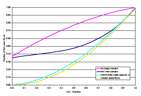
Figure 141. VAV Supply Fan Part-Load Power Coefficient Options
Enter the system behavior during times when the System Availability Schedule is zero (off). The possible inputs are StayOff, CycleOnAny, CycleOnControl Zone or CycleOnAnyZoneFansOnly. StayOff means the system will remain off, no matter how hot or cold the zones may be. CycleOnAny means that if any zone served by this system has an air temperature outside the cooling or heating set points the central fan will turn on even though the System Availability Schedule indicates the fan is off. CycleOnControlZone means the same thing except the availability manager looks at the temperature in only the zone specified in Night Cycle Control Zone Name. CycleOnAnyZoneFansOnly is the same as CycleOnAny except that only the zone fans are cycled on and the central air handler fan is left off (applicable only if using HVACTemplate:Zone:VAV:FanPowered in one or more zones). The default is StayOff.
For the Night Cycle Control option Cycle On Control Zone enter the name of the control zone. For other Night Cycle Control options, this field is ignored.
Enter the type of air-to-air heat recovery which is available between the relief air stream and the outdoor air inlet stream. The choices are:
· None
· Sensible
· Enthalpy
The default is None. If heat recovery is specified (i.e., Sensible or Enthalpy), then a value must be entered in the Minimum Outdoor Air Flow Rate field, because heat recovery equipment is not yet autosizable. The entered Minimum Outdoor Air Flow Rate is used to define the Nominal Supply Air Flow Rate for the HeatExchanger:AirToAir:SensibleAndLatent object generated by this template.
Enter the sensible heat recovery effectiveness. This is applied as a constant effectiveness at all conditions. The valid range is from 0.0 to 1.0, and the default is 0.70.
Enter the latent heat recovery effectiveness if Heat Recovery Type is Enthalpy. This is applied as a constant effectiveness at all conditions. The valid range is from 0.0 to 1.0, and the default is 0.65.
Select the type of automatic reset control for the cooling supply air temperature. The choices are:
· None – no reset, use the Cooling Coil Setpoint Schedule or Cooling Coil Design Setpoint.
· Warmest – reset the cooling supply air temperature to the highest supply air temperature that will meet the cooling requirements of all the zones. The minimum setpoint allowed is the Cooling Coil Design Setpoint. The maximum setpoint allowed is defaulted to 18C. (Reference SetpointManager:Warmest)
· OutdoorAirTemperatureReset – reset the cooling supply air temperature based on the following default rules. When the outdoor dry-bulb temperature (ODB) is at or below 15.6C the setpoint is 18.0C. When the ODB is at or above 26.7C the setpoint is the Cooling Coil Design Setpoint. In between, the setpoint is varied linearly. (Reference SetpointManager:OutdoorAirReset)
The default is None.
Select the type of automatic reset control for the central heating supply air temperature. The choices are:
· None – no reset, use the Heating Coil Setpoint Schedule or Heating Coil Design Setpoint.
· OutdoorAirTemperatureReset – reset the heating supply air temperature based on the following default rules. When the outdoor dry-bulb temperature (ODB) is at or below –6.7C the setpoint is the Heating Coil Design Setpoint. When the ODB is at or above 10.0C the setpoint is 20.0C. In between, the setpoint is varied linearly. (Reference SetpointManager:OutdoorAirReset).
The default is None.
There are two dehumidification control type options available:
· None
· CoolReheat
The CoolReheat option cools beyond the dry-bulb setpoint as required to meet the humidity setpoint if the system is capable of doing so. Reheat is provided as required by the terminal unit reheat coils if available.
The default is None which meets the sensible cooling setpoint only.
This field specifies the zone name where the humidistat is located for controlling dehumidification.
This field specifies the zone humidistat setpoint for dehumidification in percent (0 to 100). The default is 60%.
There are two humidifier type options available:
· None
· ElectricSteam
The ElectricSteam humidifier option uses the Humidifier:Steam:Electric object. The default is None.
If left blank, the humidifier will be available anytime the system is operating. If a schedule name is specified, it defines when the humidifier is available. The schedule values denote whether the humidifier can run during a given time period. A schedule value of 1.0 indicates that the humidifier can be on during a given time period. A value of zero denotes that the humidifier cannot be used during that time period
Enter the rated moisture output rate in m3/s. The humidifier does not currently autosize, so the default is very large to allow for adequate capacity. The default is 0.000001 m3/s.
Enter the electric power input at the rated capacity moisture output. The humidifier does not currently autosize, so the default power input is consistent with the default capacity input (2690 W per 0.000001 m3/s output) Power consumption is proportional to moisture output with no part-load penalty.
This field specifies the zone name where the humidistat is located for controlling humidification.
This field specifies the zone humidistat setpoint for humidification in percent (0 to 100). The default is 30%.
As shown in an IDF:
HVACTemplate:System:PackagedVAV,
DXVAV Sys 1, !- Name
FanAvailSched, !- System Availability Schedule Name
autosize, !- Supply Fan Maximum Flow Rate {m3/s}
autosize, !- Supply Fan Minimum Flow Rate {m3/s}
DrawThrough, !- Supply Fan Placement
0.7, !- Supply Fan Total Efficiency
1000, !- Supply Fan Delta Pressure {Pa}
0.9, !- Supply Fan Motor Efficiency
1, !- Supply Fan Motor in Air Stream Fraction
TwoSpeedDX, !- Cooling Coil Type
, !- Cooling Coil Availability Schedule Name
, !- Cooling Coil Setpoint Schedule Name
12.8, !- Cooling Coil Design Setpoint {C}
autosize, !- Cooling Coil Capacity {W}
autosize, !- Cooling Coil Rated Sensible Heat Ratio
3, !- Cooling Coil Rated COP
Gas, !- Heating Coil Type
, !- Heating Coil Availability Schedule Name
, !- Heating Coil Setpoint Schedule Name
10, !- Heating Coil Design Setpoint {C}
autosize, !- Heating Coil Capacity {W}
0.8, !- Gas Heating Coil Efficiency
, !- Gas Heating Coil Parasitic Electric Load {W}
autosize, !- Maximum Outdoor Air Flow Rate {m3/s}
autosize, !- Minimum Outdoor Air Flow Rate {m3/s}
ProportionalMinimum, !- Minimum Outdoor Air Control Type
Min OA Sched, !- Minimum Outdoor Air Schedule Name
DifferentialDryBulb, !- Economizer Type
NoLockout, !- Economizer Lockout
19, !- Economizer Maximum Limit Dry-Bulb Temperature {C}
, !- Economizer Maximum Limit Enthalpy {J/kg}
, !- Economizer Maximum Limit Dewpoint Temperature {C}
4, !- Economizer Minimum Limit Dry-Bulb Temperature {C}
, !- Supply Plenum Name
PLENUM-1, !- Return Plenum Name
InletVaneDampers, !- Supply Fan Part-Load Power Coefficients
CycleOnAny, !- Night Cycle Control
, !- Night Cycle Control Zone Name
None, !- Heat Recovery Type
0.7, !- Sensible Heat Recovery Effectiveness
0.65, !- Latent Heat Recovery Effectiveness
None, !- Cooling Coil Setpoint Reset Type
None, !- Heating Coil Setpoint Reset Type
None, !- Dehumidification Control Type
, !- Dehumidification Control Zone Name
60, !- Dehumidification Setpoint {percent}
None, !- Humidifier Type
, !- Humidifier Availability Schedule Name
0.000001, !- Humidifier Rated Capacity {m3/s}
2690, !- Humidifier Rated Electric Power {W}
, !- Humidifier Control Zone Name
30; !- Humidifier Setpoint {percent}
The HVACTemplate:System:DedicatedOutdoorAir creates a dedicated outdoor air system which must be used in conjunction with one or more of the following objects:
HVACTemplate:Zone:FanCoil
HVACTemplate:Zone:PTAC
HVACTemplate:Zone:PTHP
HVACTemplate:Zone:WaterToAirHeatPump
It is a constant volume dedicated outdoor air system which can serve multiple zones. It may have any combination of heating coil, cooling coil, and heat recovery. It may have dehumidification and humidification controls as well as several supply temperature control types. It supplies 100% outdoor air when the system is available, and assumes an equal volume of return air is available for heat recovery. If the system to be modeled does not have actual return ducts, but collects flow from exhaust fans to a central heat recovery point, then this approach should be equivalent. If the system does not have heat recovery and the air is exhausted or leaves by exfiltration, then the return path of this system will simply be a path to dump the flow as relief air with no impact on energy use.
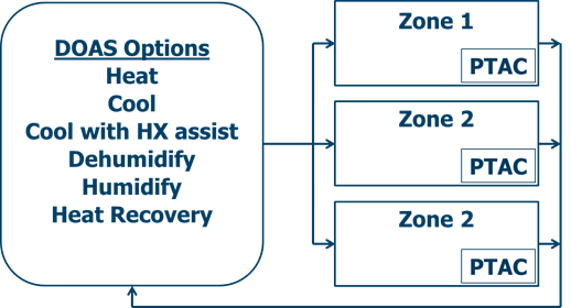
Figure 142. DOAS serving three zones with PTACs.
There may be more than one HVACTemplate:System:DedicatedOutdoorAir object in an idf file. If a zone is to be served by one of these systems, this is specified in the HVACTemplate:Zone:* object using the field “Dedicated Outdoor Air System Name”. For zones which are served by one of these DOAS systems, the outdoor air flow rate in the zone equipment (fan coil, PTAC, etc.) will be set to zero.
This field is a unique name which the user assigns to this system. This name can then be referred to in an HVACTemplate:Zone:* object to specify that this system provides outdoor air to that zone.
Leave this field blank if you want the system to operate at all times. If a schedule name is specified, those times that the system is operating should be specified as 1.0. Those times that the system is not operating should have a zero value in the schedule specified. Please note that for this system type, this is a schedule of when the system is providing air flow.
This field indicates if the air is put directly into the zones being served or into the equipment or systems that serve the spaces. For now, the only support will be for air being used directly into the zones. Only one option is available for this field: DirectIntoZone.
Enter Autosize to set the system maximum air-flow rate to the sum of the zone air flow rates. If a value is entered here for the maximum air-flow rate, it is the upper limit on system flow, even if the zone level air flow inputs sum to a greater value. The units are m3/s.
Enter the total efficiency of the supply fan. This is the ratio of the power delivered to the air to the electrical input power at maximum flow. This is also the product of the fan motor efficiency and fan (impeller) efficiency. The motor efficiency is the power delivered to the shaft divided by the electrical power input to the motor. The fan efficiency is the power delivered to the air divided by the shaft power. The power delivered to the fluid is the mass flow rate of the air multiplied by the pressure rise divided by the air density. Must be greater than 0 and less than or equal to 1.
Enter the pressure rise in Pa at full flow and standard conditions. Standard conditions are considered 20o C at sea level, 101325 Pa.
Enter the shaft power of the supply fan divided by the electrical power consumed. Must be greater than 0 and less than or equal to 1.
Enter the fraction of the motor heat that is added to the air stream. A value of 0 means that the motor is completely outside the air stream. A value of 1 means that all of the motor heat will go into the air stream and act to cause a temperature rise. Must be between 0 and 1.
Enter the supply fan placement type. This alpha field has two choices, DrawThrough or BlowThrough. DrawThrough models a system where the supply air fan is after the cooling and heating coils. BlowThrough models a system where the supply air fan is before the cooling and heating coils. The default is DrawThrough.
There are seven coil types available:
· ChilledWater
· ChilledWaterDetailedFlatModel
· TwoSpeedDX
· TwoStageDX
· TwoStageHumidControlDX
· HeatExchangerAssistedChilledWater
· HeatExchangerAssistedDX
· None
ChilledWater uses the Coil:Cooling:Water object with the DetailedAnalysis option. This is the preferred coil model for most chilled water applications.
ChilledWaterDetailedFlatModel uses the Coil:Cooling:Water:DetailedGeometry object. This option is available for special applications.
TwoSpeedDX uses the Coil:Cooling:DX:TwoSpeed object.
TwoStageDX andTwoStageHumidityControlDX use the Coil:Cooling:DX:TwoStageWithHumidityControlMode object.
HeatExchangerAssistedChilledWater uses the CoilSystem:Cooling:Water:HeatExchangerAssisted, HeatExchanger:AirToAir:SensibleAndLatent, and Coil:Cooling:Water objects.
HeatExchangerAssistedDX uses the CoilSystem:Cooling:DX:HeatExchangerAssisted, HeatExchanger:AirToAir:SensibleAndLatent, and Coil:Cooling:DX:SingleSpeed objects.
The default type is ChilledWater.
Usually left blank, which allows the cooling coil to be available anytime the system is operating. If a schedule name is specified, it defines when the coil is available. This is most often used when cooling is only available seasonally. A schedule value of one indicates that the cooling coil can be on during a given time period. A value of zero denotes that the cooling coil cannot be used during that time period.
Specifies the cooling coil setpoint control type:
· FixedSetpoint
· Scheduled
· OutdoorAirTemperatureReset
FixedSetpoint uses the Cooling Coil Design Setpoint as the supply air setpoint. Scheduled uses the Cooling Coil Setpoint Schedule to set the supply air setpoint. OutdoorAirTemperatureReset varies the supply air setpoint based on the values entered for Cooling Coil Setpoint at Outdoor Dry-Bulb Low, Cooling Coil Reset Outdoor Dry-Bulb Low, Cooling Coil Setpoint at Outdoor Dry-Bulb High, and Cooling Coil Reset Outdoor Dry-Bulb High. The default is FixedSetpoint.
NOTE: The user must ensure that the cooling coil and heating coil setpoints do not overlap to avoid unwanted simultaneous heating and cooling. The simulation will not check this automatically. It is recommended that the cooling setpoint always be at least 0.1C higher than the heating coil setpoint.
Enter the cooling supply air temperature in C to be used for sizing the cooling coil and zone supply air flow rates. The default is 12.8C. If Cooling Coil Setpoint Control Type = FixedSetpoint, then this value is used as the constant cooling supply air setpoint temperature.
This field is used when Cooling Coil Setpoint Control Type = Scheduled. The schedule should control the supply air temperature delivered to the zones. For Blow Through fan placement, this is the leaving air temperature from the cooling coil. For Draw Through fan placement, this is the leaving air temperature after the supply fan. The values in the schedule are in degrees C. This field is ignored if the Cooling Coil Setpoint Reset Type is something other than None (see below).
The cooling coil supply air setpoint temperature in C when the outdoor dry-bulb is at or below the low limit (Cooling Coil Reset Outdoor Dry Bulb Low). Used only when Cooling Coil Setpoint Control Type = OutdoorAirTemperatureReset. The default is 15.6C.
The low limit of outdoor dry-bulb temperature in C for outdoor air reset control. When the outdoor dry-bulb is at or below this temperature, the setpoint is the value of Cooling Coil Setpoint at Outdoor Dry Bulb Low. Used only when Cooling Coil Setpoint Control Type = OutdoorAirTemperatureReset. The default is 15.6C.
The cooling coil supply air setpoint temperature in C when the outdoor dry-bulb is at or above the high limit (Cooling Coil Reset Outdoor Dry Bulb Low). Used only when Cooling Coil Setpoint Control Type = OutdoorAirTemperatureReset. The default is 12.8C.
The high limit of outdoor dry-bulb temperature in C for outdoor air reset control. When the outdoor dry-bulb is at or above this temperature, the setpoint is the value of Cooling Coil Setpoint at Outdoor Dry Bulb High. Used only when Cooling Coil Setpoint Control Type = OutdoorAirTemperatureReset. The default is 23.3C.
Enter Autosize to let the automatic sizing algorithm determine the cooling coil capacity based on the maximum cooling loads during the cooling design day. If a value is entered, it represents the full load cooling capacity, including both sensible and latent capacity, in watts of the DX coil unit at rated conditions. Rated conditions are air entering the cooling coil at the maximum supply air flow rate at 26.7°C drybulb/19.4°C wetbulb with air entering the outdoor condenser coil at 35°C drybulb. Capacity should be the “gross” capacity where the impact of supply air fan heat is NOT included. The units are in W. The default is Autosize. This field is only used when the cooling coil type is set to one of the DX options. For two-speed DX coils, the low speed capacity is assumed to be 0.5 times this value. For two-stage DX coils, the stage 1 capacity is assumed to be 0.5 times this value.
Enter Autosize to allow the sizing algorithm to determine the sensible heat ratio based on the rated capacity and air flow rate. Otherwise, enter the value of the ratio of the sensible capacity divided by total cooling capacity of the DX cooling coil at rated conditions. Rated conditions are air entering the cooling coil at the maximum supply air flow rate at 26.7°C drybulb/19.4°C wetbulb with air entering the outdoor condenser coil at 35°C drybulb. Both the sensible and total cooling capacities used to define the Rated Sensible Heat Ratio (SHR) should be “gross” capacity where the impact of supply air fan heat is NOT included. The default is Autosize. This field is only used when the cooling coil type is set to one of the DX options.
Enter the coefficient of performance defined as the gross cooling coil capacity in watts divided by electrical power input in watts of the DX cooling coil unit at rated conditions. Rated conditions are air entering the cooling coil at the maximum supply air flow rate at 26.7°C drybulb/19.4°C wetbulb with air entering the outdoor condenser coil at 35°C drybulb. The input power includes electric power for the compressor and condenser fan but does not include the power consumption of the supply air fan. The default is 3.0. This field is only used when the cooling coil type is set to one of the DX options. For two-speed DX coils, the low speed COP is assumed to be 1.5 time this value. For two-stage DX coils, the stage 1 COP is assumed to be 0.9 times this value.
The heating coil is located in the supply air stream, upstream of the cooling coil. If no central heating coil is used in the dedicated outdoor air system, then the option “none” should be specified here. Otherwise this indicates the type of heating coil. The choices for this field are
· HotWater
· Electric
· Gas
· None
The default value is HotWater. If a heating coil is specified, the heating and cooling coil setpoint controls and availability schedules must coordinate to prevent the coils from opposing each other. When the dehumidification control type is set to CoolReheatHeatingCoil the heating coil is used for reheat.
Usually left blank, which allows the heating coil to be available anytime the system is operating. If a schedule name is specified, it defines when the coil is available. This is most often used when heating is only available seasonally. The schedule values denote whether the heating coil can run during a given time period. A schedule value of one indicates that the heating coil can be on during a given time period. A value of zero denotes that the heating coil cannot be used during that time period.
Specifies the cooling coil setpoint control type:
· FixedSetpoint
· Scheduled
· OutdoorAirTemperatureReset
FixedSetpoint uses the Heating Coil Design Setpoint as the supply air setpoint. Scheduled uses the Heating Coil Setpoint Schedule to set the supply air setpoint. OutdoorAirTemperatureReset varies the supply air setpoint based on the values entered for Heating Coil Setpoint at Outdoor Dry-Bulb Low, Heating Coil Reset Outdoor Dry-Bulb Low, Heating Coil Setpoint at Outdoor Dry-Bulb High, and Heating Coil Reset Outdoor Dry-Bulb High. The default is FixedSetpoint.
NOTE: The user must ensure that the cooling coil and heating coil setpoints do not overlap to avoid unwanted simultaneous heating and cooling. The simulation will not check this automatically. It is recommended that the cooling setpoint always be at least 0.1C higher than the heating coil setpoint.
Enter the heating supply air temperature in C to be used for sizing the heating coil and zone supply air flow rates. If Heating Coil Setpoint Control Type = FixedSetpoint, then this value is used as the constant heating supply air setpoint temperature. The default is 12.2C.
This field is used when Heating Coil Setpoint Control Type = Scheduled. The schedule should control the supply air temperature delivered to the zones. For Blow Through fan placement, this is the leaving air temperature from the heating coil. For Draw Through fan placement, this is the leaving air temperature after the supply fan. The values in the schedule are in degrees C.
The heating coil supply air setpoint temperature in C when the outdoor dry-bulb is at or below the low limit (Heating Coil Reset Outdoor Dry Bulb Low). Used only when Heating Coil Setpoint Control Type = OutdoorAirTemperatureReset. The default is 15.0C.
The low limit of outdoor dry-bulb temperature in C for outdoor air reset control. When the outdoor dry-bulb is at or below this temperature, the setpoint is the value of Heating coil Setpoint at Outdoor Dry Bulb Low. Used only when Heating Coil Setpoint Control Type = OutdoorAirTemperatureReset. The default is 7.8C.
The heating coil supply air setpoint temperature in C when the outdoor dry-bulb is at or above the high limit (Heating Coil Reset Outdoor Dry Bulb Low). Used only when Heating Coil Setpoint Control Type = OutdoorAirTemperatureReset. The default is 12.2C.
The high limit of outdoor dry-bulb temperature in C for outdoor air reset control. When the outdoor dry-bulb is at or above this temperature, the setpoint is the value of Heating coil Setpoint at Outdoor Dry Bulb High. Used only when Heating Coil Setpoint Control Type = OutdoorAirTemperatureReset. The default is 12.2C.
Enter gas burner efficiency as a decimal, not as a percent. A burner that is 80% efficient would have an entry of 0.8 here, which is the default. This field is only used when the heating coil type is set to gas.
Enter the parasitic electric load associated with the gas heating operation, such as a combustion fan. The units are in W. This field is only used when the heating coil type is set to gas.
Enter the type of air-to-air heat recovery which is available between the relief air stream and the outdoor air inlet stream. The choices are:
· None
· Sensible
· Enthalpy
The default is None.
Enter the sensible heat recovery effectiveness. This is applied as a constant effectiveness at all conditions. The valid range is from 0.0 to 1.0, and the default is 0.70.
Enter the latent heat recovery effectiveness if Heat Recovery Type is Enthalpy. This is applied as a constant effectiveness at all conditions. The valid range is from 0.0 to 1.0, and the default is 0.65.
This alpha field denotes the type of heat exchanger being modeled: Plate (e.g., fixed plate) or Rotary (e.g., rotating cylinder or wheel). The default choice for this field is “Plate”. The heat exchanger type affects the modeling of frost control options and supply air outlet temperature control. For rotary heat exchangers, rotational speed is varied to control frost formation or the supply air outlet temperature. For plate exchangers, air bypass around the heat exchanger is used to obtain the desired effect.
This alpha field has four choices: None, ExhaustAirRecirculation, ExhaustOnly and MinimumExhaustTemperature. If this field is left blank, the default frost control type is “None”. For modeling preheat frost control, specify “None” for this input field and insert a separate heating coil object in the supply inlet air stream to keep the air temperature above the desired frost threshold temperature.
ExhaustAirRecirculation: dampers are used to direct exhaust air back into the zone through the supply side of the heat exchanger when the supply (outdoor) air inlet temperature falls below a threshold temperature. The fraction of time that exhaust air is circulated through the supply side of the heat exchanger is dependent on the supply (outdoor) air inlet temperature with respect to the threshold temperature, the initial defrost time fraction, and the rate of change of defrost time. When exhaust air is being recirculated, no supply (outdoor ventilation) air is being provided through the heat exchanger unit (which may or may not be acceptable regarding ventilation for occupants).
ExhaustOnly (supply air bypass): this control cycles off the supply air flow through the heat exchanger for a certain period of time while the exhaust air continues to flow through the exhaust side of the heat exchanger. The fraction of time that the supply flow through the heat exchanger is cycled off is dependent on the supply (outdoor) air inlet temperature with respect to the threshold temperature, the initial defrost time fraction, and the rate of change of defrost time. When implemented in real applications, provisions are usually made to avoid building depressurization when this frost control is operating (automatic or pressure-operated dampers, or a bypass air damper around the supply side of the heat exchanger). For this frost control type, it is assumed that the supply air is bypassed around the heat exchanger during frost control operation (i.e., the total supply flow is not reduced during defrost, but merely bypassed around the heat exchanger).
MinimumExhaustTemperature: the temperature of the exhaust air leaving the heat exchanger is monitored and the heat exchanger effectiveness is decreased (by slowing heat exchanger rotation or bypassing supply air around the plate exchanger) to keep the exhaust air from falling below the threshold temperature.
There are three dehumidification control type options available:
· None
· CoolReheatHeatingCoil
· Multimode
The CoolReheatHeatingCoil and CoolReheatDesuperheater options cool beyond the dry-bulb setpoint as required to meet the humidity setpoint if the system is capable of doing so. Reheat is provided as required by the heating coil, if available. Multimode is only applicable for cooling coil type TwoStageHumidControlDX.
The default is None which meets the sensible dry-bulb temperature cooling setpoint only.
This field specifies the zone humidistat setpoint for dehumidification as a humidity ratio. The default is 0.00924 kg-H2O/kg-air (12.8C or 55F dewpoint). This value is also used as the Central Cooling Design Supply Air Humidity Ratio in the Sizing:System object.
There are two humidifier type options available:
· None
· ElectricSteam
The ElectricSteam humidifier option uses the Humidifier:Steam:Electric object. The default is None.
If left blank, the humidifier will be available anytime the system is operating. If a schedule name is specified, it defines when the humidifier is available. The schedule values denote whether the humidifier can run during a given time period. A schedule value of 1.0 indicates that the humidifier can be on during a given time period. A value of zero denotes that the humidifier cannot be used during that time period.
Enter the rated moisture output rate in m3/s. The humidifier does not currently autosize, so the default is very large to allow for adequate capacity. The default is 0.000001 m3/s.
Enter the electric power input at the rated capacity moisture output. The humidifier does not currently autosize, so the default power input is consistent with the default capacity input (2690 W per 0.000001 m3/s output) Power consumption is proportional to moisture output with no part-load penalty.
This field specifies the zone humidistat setpoint for humidification as a humidity ratio. The default is 0.003 kg-H2O/kg-air. This value is also used as the Central Heating Design Supply Air Humidity Ratio in the Sizing:System object.
As shown in an IDF:
HVACTemplate:System:DedicatedOutdoorAir,
DOAS, !- Name
, !- System Availability Schedule Name
DirectIntoZone, !- Air Outlet Type
autosize, !- Supply Fan Flow Rate {m3/s}
0.7, !- Supply Fan Total Efficiency
1000, !- Supply Fan Delta Pressure {Pa}
0.9, !- Supply Fan Motor Efficiency
1, !- Supply Fan Motor in Air Stream Fraction
DrawThrough, !- Supply Fan Placement
ChilledWater, !- Cooling Coil Type
, !- Cooling Coil Availability Schedule Name
FixedSetpoint, !- Cooling Coil Setpoint Control Type
, !- Cooling Coil Setpoint Schedule Name
12.8, !- Cooling Coil Design Setpoint {C}
15.6, !- Cooling Coil Setpoint at Outdoor Dry-Bulb Low {C}
15.6, !- Cooling Coil Reset Outdoor Dry-Bulb Low {C}
12.8, !- Cooling Coil Setpoint at Outdoor Dry-Bulb High {C}
23.3, !- Cooling Coil Reset Outdoor Dry-Bulb High {C}
autosize, !- DX Cooling Coil Capacity {W}
autosize, !- DX Cooling Coil Rated Sensible Heat Ratio
3, !- DX Cooling Coil Rated COP
HotWater, !- Heating Coil Type
, !- Heating Coil Availability Schedule Name
FixedSetpoint, !- Heating Coil Setpoint Control Type
, !- Heating Coil Setpoint Schedule Name
12.2, !- Heating Coil Design Setpoint {C}
15, !- Heating Coil Setpoint at Outdoor Dry-Bulb Low {C}
7.8, !- Heating Coil Reset Outdoor Dry-Bulb Low {C}
12.2, !- Heating Coil Setpoint at Outdoor Dry-Bulb High {C}
12.2, !- Heating Coil Reset Outdoor Dry-Bulb High {C}
0.8, !- Gas Heating Coil Efficiency
, !- Gas Heating Coil Parasitic Electric Load {W}
Enthalpy, !- Heat Recovery Type
0.7, !- Sensible Heat Recovery Effectiveness
0.65, !- Latent Heat Recovery Effectiveness
Plate, !- Heat Exchanger Type
None, !- Frost Control Type
None, !- Dehumidification Control Type
0.00924, !- Dehumidification Setpoint {kg-H2O/kg-air}
None, !- Humidifier Type
, !- Humidifier Availability Schedule Name
0.000001, !- Humidifier Rated Capacity {m3/s}
2690, !- Humidifier Rated Electric Power {W}
0.003; !- Humidifier Setpoint {kg-H2O/kg-air}
The piping systems that connect the chilled water coils in the HVAC template objects with the chillers and the cooling towers (if present) are described with this object. The piping systems are called loops and this object describes the controls and pumps on the loops. Only one of these objects may be defined in an input file and all chilled water coils from HVAC template objects are served with this object.
The name used to designate the HVACTemplate:Plant:ChilledWaterLoop.
Leave this field blank if the chilled water and condenser water pumps are always available. If a schedule name is specified, those times that the pumps are available should be specified as 1.0. Those times that the pumps are not available should have a zero value in the schedule specified. Please note that this is not a schedule of when the system is providing chilled water to the coils but a schedule of when it can provide chilled water to the coils.
Applies to both chilled water and condenser loop pumps. The choices for this field are:
· Intermittent
· Continuous
The default value is Intermittent.
If the pump control type is Continuous, the pump will run according to the Pump Schedule (see above) regardless of whether or not there is a load. If the pump control type is Intermittent, the pump will run if a load is sensed and will shut off if there is no load on the loop.
The choices for this field are:
· Default
· UserDefined
Default operation type makes all equipment available at all times operating in order of Priority specified in HVACTemplate:Plant:Chiller objects. If a different scheme is to be used to sequence the chillers, then this entry should be set to User Defined. If the User Defined option is chosen, then additional EnergyPlus objects must be included and completely defined in the IDF file such as shown below depending on the type of plant operation control scheme chosen:
· PlantEquipmentOperationSchemes
· PlantEquipmentOperation:CoolingLoad
· PlantEquipmentList (refer to HVACTemplate:Plant:Chiller object description for chiller key name required in this object).
The default value is Default.
This field should contain the name of a PlantEquipmentOperationSchemes object only when the previous field is set to UserDefined. It is ignored if Chiller Plant Operation Scheme Type is Default.
Enter the name of a chilled water setpoint schedule that has values that change at different times of the year. If a constant set point is needed simply leave this field blank and the value in the next field will be used at all times. The values in the schedule are in degrees C. This field is ignored if the Chilled Water Setpoint Reset Type is something other than None.
Enter the chilled water setpoint temperature to be used for sizing the chilled water loop and associated equipment in degrees C. If the Chilled Water Setpoint Schedule is blank and the Chilled Water Setpoint Reset Type is None, then this value will be used as the setpoint at all times.
The choices for this field are
· VariablePrimaryNoSecondary – variable flow to chillers and coils
· ConstantPrimaryNoSecondary – constant flow to chillers and coils with bypass
· ConstantPrimaryVariableSecondary – constant flow to chillers with bypass, variable flow to coils
· VariablePrimaryConstantSecondary – variable flow to chillers, constant flow to coils with bypass
The default value is ConstantPrimaryNoSecondary.
The operation of a constant speed pump is fairly straightforward. If the user designates a constant speed pump that is operating continuously, the pump will run regardless of whether or not there is a load. This may have the net effect of adding heat to the loop if no equipment is turned on. If the pump is constant speed and operates intermittently, the pump will run at its capacity if a load is sensed and will shut off if there is no load on the loop.
A variable speed pump is defined with maximum and minimum flow rates that are the physical limits of the device. If there is no load on the loop and the pump is operating intermittently, then the pump can shutdown. For any other condition such as the loop having a load and the pump is operating intermittently or the pump is continuously operating (regardless of the loading condition), the pump will operate and select a flow somewhere between the minimum and maximum limits. In these cases where the pump is running, it will try to meet the flow request made by demand side components.
The rated head of the primary chilled water pump in Pa. The default value is 179352 Pa which is equivalent to 60 feet H2O.
The rated head of the secondary chilled water pump in Pa. The default value is 179352 Pa which is equivalent to 60 feet H2O. This field is applicable only if the “Chilled Water Pump Configuration” is Constant Primary Variable Secondary or Variable Primary Constant Secondary.
The choices for this field are:
· Default
· UserDefined
Default operation type makes all equipment available at all times operating in order of Priority specified in HVACTemplate:Plant:Tower objects. If a different scheme is to be used to sequence the towers, then this entry should be set to User Defined. May be left blank if not serving any water cooled chillers.
If User Defined option is chosen, then additional EnergyPlus objects must be included and completely defined in the IDF file such as shown below depending on the type of condenser operation control scheme chosen:
· CondenserEquipmentOperationSchemes
· PlantEquipmentOperation:CoolingLoad
· PlantEquipmentList (refer to the HVACTemplate:Plant:Tower object description for key name required for this object.
The default value is Default.
This field should contain the name of a CondenserEquipmentOperationSchemes object only when the previous field is set to UserDefined. It is ignored if Condenser Plant Operation Scheme Type is Default. May be left blank if not serving any water cooled chillers.
If water cooled chillers are present the condenser water temperature control can be one of the following options:
· OutdoorWetBulbTemperature
· SpecifiedSetpoint
If a specified set point is used then the towers are operated to deliver that condenser water set point. If outdoor wet-bulb is used then the condenser water temperature decreases with decreasing outdoor wet-bulb temperature. May be left blank if not serving any water cooled chillers.
Used when Condenser Water Temperature Control Type is set to Specified Setpoint. Ignored if Condenser Water Temperature Control Type is set to Outdoor Wet-bulb. The field may be left blank if constant setpoint temperature is used for the condenser water temperature. If may also be left blank if not serving any water cooled chillers. If specified, the schedule should contain the set point temperatures in degrees C for the condenser water loop.
Enter the condenser water temperature to be used for sizing the condenser loop and associated equipment. If a constant setpoint control is used for the condenser water, this value will be used as the setpoint at all times. May be left blank if not serving any water cooled chillers. Used when Condenser Water Temperature Control Type is set to Specified Setpoint. Ignored if Condenser Water Temperature Control Type is set to Outdoor Wet Bulb. The units are in C.
The rated head of the condenser water pumps in Pa. May be left blank if not serving any water cooled chillers. The default value is 179352 Pa which is equivalent to 60 feet H2O.
Select the type of automatic reset control for the chilled water supply temperature. The choices are:
· None – no reset, use the Chilled Water Setpoint Schedule or Chilled Water Design Setpoint.
· OutdoorAirTemperatureReset – reset the chilled water supply temperature based on the following default rules. The temperature limits and setpoints are specified using the fields below. If the default values are used, when the outdoor dry-bulb temperature (ODB) is at or below 15.6C the setpoint is 12.2C. When the ODB is at or above 26.7C the setpoint is 6.7C. In between, the setpoint is varied linearly. (Reference SetpointManager:OutdoorAirReset)
The default is None.
The chilled water setpoint temperature in C when the outdoor dry-bulb is at or below the low limit (Chilled Water Reset Outdoor Dry Bulb Low). The default is 12.2C.
The low limit of outdoor dry-bulb temperature in C for outdoor air reset control. When the outdoor dry-bulb is at or below this temperature, the setpoint is the value of Chilled Water Setpoint at Outdoor Dry Bulb Low. The default is 15.6C.
The chilled water setpoint temperature in C when the outdoor dry-bulb is at or above the high limit (Chilled Water Reset Outdoor Dry Bulb Low). The default is 6.7C.
The high limit of outdoor dry-bulb temperature in C for outdoor air reset control. When the outdoor dry-bulb is at or above this temperature, the setpoint is the value of Chilled Water Setpoint at Outdoor Dry Bulb High. The default is 26.7C.
As shown in an IDF:
HVACTemplate:Plant:ChilledWaterLoop,
Chilled Water Loop, !- Plant Loop Name
CoolingPumpAvailSched, !- Pump Schedule
Intermittent, !- Pump Control Type
Default, !- Chiller Plant Operation Scheme Type
, !- Chiller Plant Operation Scheme Name
CW Loop Temp Schedule, !- Chilled Water Setpoint Schedule
7.22, !- Chilled Water Design Setpoint {C}
VariableFlowNoSecondary, !- Chilled Water Pump Configuration
179352, !- Primary Chilled Water Pump Rated Head {Pa}
179352, !- Secondary Chilled Water Pump Rated Head {Pa}
Default, !- Condenser Plant Operation Scheme Type
, !- Condenser Plant Operation Scheme List Name
OutdoorWetBulbTemperature, !- Condenser Water Temperature Control Type
, !- Condenser Water Setpoint Schedule
29.4, !- Condenser Water Design Setpoint {C}
179352, !- Condenser Water Pump Rated Head {Pa}
None, !- Chilled Water Setpoint Reset Type
12.2, !- Chilled Water Setpoint at Outdoor Dry Bulb Low {C}
15.6, !- Chilled Water Reset Outdoor Dry Bulb Low {C}
6.7, !- Chilled Water Setpoint at Outdoor Dry Bulb High {C}
26.7; !- Chilled Water Reset Outdoor Dry Bulb High {C}
A chiller or purchased cooling source is described with this object. To define multiple chillers, use multiple HVACTemplate:Plant:Chiller objects and use the Sizing Factor field to apportion the total capacity if autosizing.
The name used to reference the HVACTemplate:Plant:Chiller object.
While EnergyPlus has a variety of chiller options, the only choices currently for this field are:
· DistrictChilledWater
· ElectricCentrifugalChiller
· ElectricScrewChiller
· ElectricReciprocatingChiller
The EnergyPlus equipment object types which are used are DistrictCooling or Chiller:Electric:EIR. These equipment type keys must be used if setting up a user-defined chiller plant operation scheme.
This field may be set to autosize, which means that the capacity is based on the peak loads during the design days. This numeric field contains the design cooling capacity of the chiller. This capacity should be at the design temperatures and water flow rates. The units are in W.
This numeric field contains the chiller’s coefficient of performance. This value should not include energy use due to pumps, evap-cooled or air-cooled condenser fans, or cooling tower fans. This Nominal COP should be at the design temperatures and water flow rates. Not applicable if Chiller Type is DistrictChilledWater.
The choices for this field are
· AirCooled
· WaterCooled
· EvaporativelyCooled
The default value is WaterCooled. If WaterCooled, then at least one HVACTemplate:Plant:Tower object should be defined. Not applicable if Chiller Type is Purchased Chilled Water.
Enter the priority number of the chiller where 1 is the highest priority, 2 is just lower, 3 is lower than 2, etc. This is used if Chiller Plant Operation Scheme Type is set to Default in HVACTemplate:Plant:ChilledWaterLoop. Equipment is operated in order of the priority number. This allows multiple chillers to be sequenced.
This optional numeric field allows the user to specify a sizing factor for this component. The sizing factor is used when the component design inputs are autosized: the autosizing calculations are performed as usual and the results are multiplied by the sizing factor. For this component the chiller object inputs that would be altered by the sizing factor are: Reference Capacity, Reference Chilled Water Flow Rate and Reference Condenser Water Flow Rate. Sizing Factor allows the user to size a component to meet part of the design load while continuing to use the autosizing feature.
As shown in an IDF:
HVACTemplate:Plant:Chiller,
District Cooling, !- Chiller Name
ElectricCentrifugalChiller, !- Chiller Type
autosize, !- Capacity {W}
3.2, !- COP
WaterCooled, !- Condenser Type
1, !- Priority
1.0; !- Sizing Factor
A cooling tower is described with this object. To define multiple cooling towers, use multiple HVACTemplate:Plant:Tower objects and use the Sizing Factor field to apportion the total capacity if autosizing.
The name used to reference the HVACTemplate:Plant:Tower object.
The choices for this field are
· SingleSpeed
· TwoSpeed
The EnergyPlus equipment object types which are used are CoolingTower:SingleSpeed or CoolingTower:TwoSpeed. These equipment type keys must be used if setting up a user-defined condenser plant operation scheme.
Applicable for Tower Type Single Speed and Two Speed. This field may be set to autosize. If this field is set to autosize, then the Low-Speed Nominal Capacity and the Free Convection Capacity must also be autosized. The units are W. This numeric input field contains the “nominal” heat rejection capacity of the cooling tower in watts under high-speed fan operation, with entering water at 35C (95F), leaving water at 29.4C (85F), entering air at 25.6C (78F) wetbulb and 35C (95F) drybulb temperatures. The design water flow rate is assumed to be 5.382E-8 m3/s per watt of high-speed nominal capacity (3 gpm/ton). 125% of this nominal tower capacity gives the actual tower heat rejection at these operating conditions (based on historical assumption that the tower must dissipate 0.25W of compressor heat for every watt of heat removed by the evaporator).
The tower fan electric consumption when at high speed. Applicable for Tower Type Single Speed and Two Speed. This field may be set to autosize. The units are W.
Applicable only for Tower Type Two Speed. This field may be set to autosize. If this field is set to autosize, then the High-Speed Nominal Capacity and the Free Convection Capacity must also be autosized. The units are W. This numeric input field contains the “nominal” heat rejection capacity of the cooling tower in watts under low-speed fan operation, with entering water at 35C (95F), leaving water at 29.4C (85F), entering air at 25.6C (78F) wetbulb and 35C (95F) drybulb temperatures. The design water flow rate is assumed to be 5.382E-8 m3/s per watt of high-speed nominal tower capacity (input field above). 125% of this nominal tower capacity gives the actual tower heat rejection at these operating conditions (based on historical assumption that the tower must dissipate 0.25W of compressor heat for every watt of heat removed by the evaporator). The value specified for this field must be greater than zero but less than the value specified for the field “Tower High-Speed Nominal Capacity”.
The tower fan electric consumption when at low speed. Applicable only for Tower Type Two Speed. This field may be set to autosize. The units are W.
Applicable for Tower Type Single Speed and Two Speed. This field may be set to autosize. If this field is set to autosize, then the High-Speed Nominal Capacity and the Low-Speed Nominal Capacity must also be autosized. The units are W. This numeric input field contains the “nominal” heat rejection capacity of the cooling tower in watts when the tower is in the “free convection” regime (water flow exists but tower fan is turned off), with entering water at 35C (95F), leaving water at 29.4C (85F), entering air at 25.6C (78F) wetbulb and 35C (95F) drybulb temperatures. The design water flow rate is assumed to be 5.382E-8 m3/s per watt of high-speed nominal tower capacity (input field above). 125% of this free convection tower capacity gives the actual tower heat rejection at these operating conditions (based on historical assumption that the tower must dissipate 0.25W of compressor heat for every watt of heat removed by the evaporator). If the user does not wish to model “free convection”, then this field should be set to 0.0.
Enter the priority number of the tower where 1 is the highest priority, 2 is just lower, 3 is lower than 2, etc. This is used if Condenser Plant Operation Scheme Type is set to Default in HVACTemplate:Plant:ChilledWaterLoop. Equipment is operated in order of the priority number. This allows multiple towers to be sequenced.
Field: Sizing Factor
This optional numeric field allows the user to specify a sizing factor for this component. The sizing factor is used when the component design inputs are autosized: the autosizing calculations are performed as usual and the results are multiplied by the sizing factor. Sizing factor allows the user to size a component to meet part of the design load while continuing to use the autosizing feature.For this component the tower object inputs that would be altered by the sizing factor are:
1. Design Water Flow Rate;
2. Air Flow Rate at High Fan Speed;
3. Fan Power at High Fan Speed;
4. U-Factor Times Area Value at High Fan Speed;
5. Air Flow Rate at Low Fan Speed (for two-speed tower);
6. Fan Power at Low Fan Speed (for two-speed tower);
7. U-Factor Times Area Value at Low Fan Speed (for two-speed tower);
8. Air Flow Rate in Free Convection Regime;
9. U-Factor Times Area Value at Free Convection Air Flow Rate.
Note that the U-Factor Times Area Value at High Fan Speed is not multiplied by the Sizing Factor. Instead the design tower load is multiplied by the sizing factor and the design UA then calculated as usual. The U-Factor Times Area Value at Low Fan Speed is set to 60% of the full load design UA. The U-Factor Times Area Value at Free Convection Air Flow Rate is set to 10% of the design Tower UA.
An example in an IDF:
HVACTemplate:Plant:Tower,
Main Tower, !- Name
SingleSpeed, !- Tower Type
autosize, !- High Speed Nominal Capacity {W}
autosize, !- High Speed Fan Power {W}
autosize, !- Low Speed Nominal Capacity {W}
autosize, !- Low Speed Fan Power {W}
autosize, !- Free Convection Capacity {W}
1, !- Priority
; !- Sizing Factor
The piping systems that connect the hot water coils in the HVAC template objects with the boilers are described with this object. The piping systems are called loops and this object describes the controls and pumps on the loops. Only one of these objects should be defined in an input file and all hot water coils from HVAC template objects are served with this object.
The name used to designate the HVACTemplate:Plant:HotWaterLoop.
Leave this field blank if the hot water pump is always available. If a schedule name is specified, those times that the pump is available should be specified as 1.0. Those times that the pump is not available should have a zero value in the schedule specified. Please note that this is not a schedule of when the system is providing hot water to the coils but a schedule of when it can provide hot water to the coils.
The choices for this field are
· Intermittent
· Continuous
The default value is Intermittent.
If the pump control type is Continuous, the pump will run according to the Pump Schedule (see above) regardless of whether or not there is a load. If the pump control type is Intermittent, the pump will run if a load is sensed and will shut off if there is no load on the loop.
The choices for this field are:
· Default
· UserDefined
Default operation type makes all equipment available at all times operating in order of Priority specified in HVACTemplate:Plant:Boiler objects. If a different scheme is to be used to sequence the boilers, then this entry should be set to User Defined.
If User Defined option is chosen, then additional EnergyPlus objects must be defined in the IDF file such as shown below depending on the type of plant operation control scheme chosen:
· PlantEquipmentOperationSchemes
· PlantEquipmentOperation:HeatingLoad
· PlantEquipmentList (refer to HVACTemplate:Plant:Boiler object description for key name required in this object)
The default value is Default.
This field should contain the name of a PlantEquipmentOperationSchemes object only when the previous field is set to User Defined. It is ignored if Hot Water Plant Operation Scheme Type is Default.
Enter the name of a hot water setpoint schedule that has values that change at different times of the year. If a constant set point is needed simply leave this field blank and the value in the next field will be used at all times. The values in the schedule are in degrees C. This field is ignored if the Hot Water Setpoint Reset Type is something other than None.
Enter the hot water setpoint temperature to be used for sizing the hot water loop and associated equipment in degrees C. If the Hot Water Setpoint Schedule is blank and the Hot Water Setpoint Reset Type is None, then this value will be used as the setpoint at all times.
The choices for this field are
· VariableFlow
· ConstantFlow
The default value is ConstantFlow. The variable flow option simulates a pump with variable flow to boilers and coils, excess bypassed. The constant flow option simulates constant flow to boilers and coils, excess bypassed.
The operation of a constant speed pump is fairly straightforward. If the user designates a constant speed pump that is operating continuously, the pump will run regardless of whether or not there is a load. This may have the net effect of adding heat to the loop if no equipment is turned on. If the pump is constant speed and operates intermittently, the pump will run at its capacity if a load is sensed and will shut off if there is no load on the loop.
A variable speed pump is defined with maximum and minimum flow rates that are the physical limits of the device. If there is no load on the loop and the pump is operating intermittently, then the pump can shutdown. For any other condition such as the loop having a load and the pump is operating intermittently or the pump is continuously operating (regardless of the loading condition), the pump will operate and select a flow somewhere between the minimum and maximum limits. In these cases where the pump is running, it will try to meet the flow request made by demand side components.
The rated head of the hot water pump in Pa. The default value is 179352 Pa which is equivalent to 60 feet H2O.
Select the type of automatic reset control for the Hot Water supply temperature. The choices are:
· None – no reset, use the Hot Water Setpoint Schedule or Hot Water Design Setpoint.
· OutdoorAirTemperatureReset – reset the Hot Water supply temperature based on the following default rules. The temperature limits and setpoints are specified using the fields below. If the default values are used, when the outdoor dry-bulb temperature (ODB) is at or below –6.7C the setpoint is 82.2C. When the ODB is at or above 10.0C the setpoint is 65.6C. In between, the setpoint is varied linearly. (Reference SetpointManager:OutdoorAirReset)
The default is None.
The Hot Water setpoint temperature in C when the outdoor dry-bulb is at or below the low limit (Hot Water Reset Outdoor Dry Bulb Low). The default is –6.7C.
The low limit of outdoor dry-bulb temperature in C for outdoor air reset control. When the outdoor dry-bulb is at or below this temperature, the setpoint is the value of Hot Water Setpoint at Outdoor Dry Bulb Low. The default is 82.2C.
The Hot Water setpoint temperature in C when the outdoor dry-bulb is at or above the high limit (Hot Water Reset Outdoor Dry Bulb Low). The default is 10.0C.
The high limit of outdoor dry-bulb temperature in C for outdoor air reset control. When the outdoor dry-bulb is at or above this temperature, the setpoint is the value of Hot Water Setpoint at Outdoor Dry Bulb High. The default is 65.6C.
As shown in an IDF:
HVACTemplate:Plant:HotWaterLoop,
Hot Water Loop, !- Plant Loop Name
, !- Pump Schedule
Intermittent, !- Pump Control Type
Default, !- Hot Water Plant Operation Scheme Type
, !- Hot Water Plant Operation Scheme List Name
HW Loop Temp Schedule, !- Hot Water Setpoint Schedule
82, !- Hot Water Design Setpoint {C}
VariableFlow, !- Hot Water Pump Configuration
179352, !- Hot Water Pump Rated Head {Pa}
None, !- Hot Water Setpoint Reset Type
82.2, !- Hot Water Setpoint at Outdoor Dry Bulb Low {C}
-6.7, !- Hot Water Reset Outdoor Dry Bulb Low {C}
65.6, !- Hot Water Setpoint at Outdoor Dry Bulb High {C}
10; !- Hot Water Reset Outdoor Dry Bulb High {C}
A boiler or purchased heating source is described with this object. To define multiple boilers, use multiple HVACTemplate:Plant:Boiler objects and use the Sizing Factor field to apportion the total capacity if autosizing.
The name used to reference the HVACTemplate:Plant:Boiler object.
While EnergyPlus has a variety of boiler options, the only choices currently for this field are:
· DistrictHotWater
· HotWaterBoiler
The EnergyPlus equipment object types which are used are DistrictHeating or Boiler:HotWater. These equipment type keys must be used if setting up a user-defined chiller plant operation scheme.
This field may be set to autosize, which means that the capacity is based on the peak loads during the design days. This numeric field contains the design heating capacity of the boiler. This capacity should be at the design water flow rates. The units are in W.
This numeric field contains the heating efficiency (as a fraction between 0 and 1) of the boiler’s burner. Not applicable if Boiler Type is DistrictHotWater.
The choices for this field are
· Electricity
· NaturalGas
· PropaneGas
· FuelOil#1
· FuelOil#2
· Coal
· Diesel
· Gasoline
Not applicable if Boiler Type is DistrictHotWater
Enter the priority number of the boiler where 1 is the highest priority, 2 is just lower, 3 is lower than 2, etc. This is used if Boiler Plant Operation Scheme Type is set to Default in HVACTemplate:Plant:HotWaterLoop. Equipment is operated in order of the priority number. This allows multiple boilers to be sequenced.
This optional numeric field allows the user to specify a sizing factor for this component. The sizing factor is used when the component design inputs are autosized: the autosizing calculations are performed as usual and the results are multiplied by the sizing factor. For this component the boiler object inputs that would be altered by the sizing factor are: Nominal Capacity and Design Water Flow Rate. Sizing factor allows the user to size a component to meet part of the design load while continuing to use the autosizing feature.
An example in an IDF:
HVACTemplate:Plant:Boiler,
Main Boiler, !- Name
HotWaterBoiler, !- Boiler Type
autosize, !- Capacity {W}
0.8, !- Efficiency
NaturalGas, !- Fuel Type
1, !- Priority
; !- Sizing Factor
This object simulates the central plant loop portion of a water source heat pump system. Often many HVACTemplate:Zone:WaterToAirHeatPump objects will be used in a building along with a single HVACTemplate:Plant:MixedWaterLoop that contains one or more cooling towers and boilers. The piping systems are called loops and this object describes the controls and pumps on the loops. Only one of these objects should be defined in an input file.
Note: documentation developed primarily by modifying HVACTemplate:Plant:HotWaterLoop and HVACTemplate:Plant:ChilledWaterLoop
The name used to designate the HVACTemplate:Plant:MixedWaterLoop.
Leave this field blank if the water pump is always available. If a schedule name is specified, those times that the pump is available should be specified as 1.0. Those times that the pump is not available should have a zero value in the schedule specified. Please note that this is not a schedule of when the system is providing water to the water-to-air heat pumps but a schedule of when it can provide water to the water-to-air heat pumps.
The choices for this field are
· Intermittent
· Continuous
The default value is Intermittent.
If the pump control type is Continuous, the pump will run according to the Pump Schedule (see above) regardless of whether or not there is a load. If the pump control type is Intermittent, the pump will run if a load is sensed and will shut off if there is no load on the loop.
The choices for this field are:
· Default
· UserDefined
Default operation type makes all equipment available at all times operating in order of Priority specified in HVACTemplate:Plant:Boiler objects. If a different scheme is to be used to sequence the boilers, then this entry should be set to User Defined.
If User Defined option is chosen, then additional EnergyPlus objects must be defined in the IDF file such as shown below depending on the type of plant operation control scheme chosen:
· PlantEquipmentOperationSchemes
· PlantEquipmentOperation:CoolingLoad
· PlantEquipmentOperation:HeatingLoad
· PlantEquipmentList (refer to HVACTemplate:Plant:Boiler object description for key name required in this object)
The default value is Default.
This field should contain the name of a PlantEquipmentOperationSchemes object only when the previous field is set to User Defined. It is ignored if Hot Water Plant Operation Scheme Type is Default.
Enter the name of a high temperature setpoint schedule that has values that change at different times of the year. If a constant set point is needed simply leave this field blank and the value in the next field will be used at all times. The values in the schedule are in degrees C.
Enter the high temperature setpoint temperature to be used for sizing the water loop and associated equipment in degrees C. If the High Temperature Setpoint Schedule is blank, then this value will be used as the setpoint at all times. The default is 33C.
Enter the name of a low temperature setpoint schedule that has values that change at different times of the year. If a constant set point is needed simply leave this field blank and the value in the next field will be used at all times. The values in the schedule are in degrees C.
Enter the low temperature setpoint temperature to be used for sizing the water loop and associated equipment in degrees C. If the Low Temperature Setpoint Schedule is blank, then this value will be used as the setpoint at all times. The default is 20C.
The choices for this field are
· VariableFlow
· ConstantFlow
The default value is ConstantFlow. The variable flow option simulates a pump with variable flow to boilers, cooling towers, and water to air heat pump, excess bypassed. The constant flow option simulates constant flow to boilers, cooling towers, and water to air heat pumps, excess bypassed.
The operation of a constant speed pump is fairly straightforward. If the user designates a constant speed pump that is operating continuously, the pump will run regardless of whether or not there is a load. This may have the net effect of adding heat to the loop if no equipment is turned on. If the pump is constant speed and operates intermittently, the pump will run at its capacity if a load is sensed and will shut off if there is no load on the loop.
A variable speed pump is defined with maximum and minimum flow rates that are the physical limits of the device. If there is no load on the loop and the pump is operating intermittently, then the pump can shutdown. For any other condition such as the loop having a load and the pump is operating intermittently or the pump is continuously operating (regardless of the loading condition), the pump will operate and select a flow somewhere between the minimum and maximum limits. In these cases where the pump is running, it will try to meet the flow request made by demand side components.
The rated head of the hot water pump in Pa. The default value is 179352 Pa which is equivalent to 60 feet H2O.
As shown in an IDF:
HVACTemplate:Plant:MixedWaterLoop,
Only Water Loop, !- Name
, !- Pump Schedule Name
Intermittent, !- Pump Control Type
Default, !- Operation Scheme Type
, !- Equipment Operation Schemes Name
, !- High Temperature Setpoint Schedule Name
34, !- High Temperature Design Setpoint {C}
, !- Low Temperature Setpoint Schedule Name
20, !- Low Temperature Design Setpoint {C}
ConstantFlow, !- Water Pump Configuration
179352; !- Water Pump Rated Head {Pa}
EnergyPlus contains a number of objects to model construction cost and utility bill calculations.
The objects used by EnergyPlus for construction cost calculations are as follows:
n ComponentCost:Adjustments
n ComponentCost:Reference
n ComponentCost:LineItem
The objects used by EnergyPlus for utility bill calculations are as follows:
n UtilityCost:Tariff
n UtilityCost:Qualify
n UtilityCost:Charge:Simple
n UtilityCost:Charge:Block
n UtilityCost:Ratchet
n UtilityCost:Variable
n UtilityCost:Computation
The objects used for performing a life-cycle cost analysis are:
n LifeCycleCost:Parameters
n LifeCycleCost:RecurringCosts
n LifeCycleCost:NonrecurringCost
n LifeCycleCost:UsePriceEscalation
n LifeCycleCost:UseAdjustment
The object used for specifying the currency symbol of the monetary unit used is:
n CurrencyType
While it is true that monthly utility bills are often directly related to monthly energy consumption and monthly peak demand, due to the elaborate regulatory environment and the changing value of the energy based on load factor, the calculations involved are often complicated. The EnergyPlus approach is to allow you to model the individual component charges that make up the utility bill and report the results on a monthly basis.
To show you how simple the specification of a rate can be here is a simple example for a flat charge of 8 cents for every kWh sold.
UtilityCost:Tariff,
TariffExample1, ! Name
Electricity:Facility, ! Output Meter Name
kWh; ! Conversion Factor Choice
UtilityCost:Charge:Simple,
ChargeExample1, ! Charge Variable Name
TariffExample1, ! Tariff Name
totalEnergy, ! Source Variable
Annual, ! Season
EnergyCharges, ! Category Variable Name
0.08; ! Cost Per Unit Value or Variable Name
Overall, the goals of the economics section of EnergyPlus are to make simple tariffs easy to model and complex tariffs possible to model.
The cost implications of alternative, energy-related design options may be important in determining the whether or not a particular design is viable. Although the main purpose of EnergyPlus is to determine the energy performance of a building, component cost modeling is provided to allow estimating initial construction costs associated with the building and HVAC system being modeled. This is provided in order to ensure that cost estimates are consistent with the EnergyPlus model and it allows using results calculated during a simulation such as equipment sizes and surface areas. The cost estimating capabilities are not comprehensive and are not intended to duplicate all the types of analyses included in cost estimating software. Economics modeling is being implemented in stages. Future versions of EnergyPlus will add other investment related analyses such as life-cycle cost. The objects used by EnergyPlus for calculating first costs for construction projects are as follows:
n ComponentCost:Adjustments
n ComponentCost:Reference
n ComponentCost:LineItem
The results of the cost estimate are reported in a Construction Cost Estimate Summary table provided that the user requests the results using the object Output:Table:SummaryReports object with the Component Cost Economics Summary option selected. The style of this predefined report can be controlled using the OutputControl:Table:Style object. If the Annual Building Performance Report Summary is also requested, then cost estimate results will follow that data in the same output file.
The rest of this Economics section is organized to first present reference material on tariff calculations followed by construction cost estimating.
To understand how to use the utility bill calculation portion of EnergyPlus you first need to understand some important concepts of variables and hierarchy. A variable, for the purposes of this section, is simply a named holder of a series of numbers. In most cases, the variable will be a named holder of 12 numbers, one number for each monthly utility bill. Here is a visualization of a variable called Electric Energy Use:
Table 35. Example Electric Energy Use (for Economics Calculation)
|
Month |
Electric Energy Use |
|
January |
12143 |
|
February |
13454 |
|
March |
14178 |
|
April |
14876 |
|
May |
15343 |
|
June |
16172 |
|
July |
16105 |
|
August |
15762 |
|
September |
14543 |
|
October |
13987 |
|
November |
13287 |
|
December |
12403 |
If you have ever done any computer programming, you can think of a variable as an array. Many of the names used in the utility bill calculation portion of EnergyPlus are names of variables. In the case of the UtilityCost:Charge objects, the name of the object is also used as a name of a variable.
In many of today’s utility rates, the charges for energy or demand are broken into distribution and supply charges. To allow for this, more than one charge may to be defined for a particular category. The variables assigned to the same category are added together.
The categories are combined in following hierarchy:
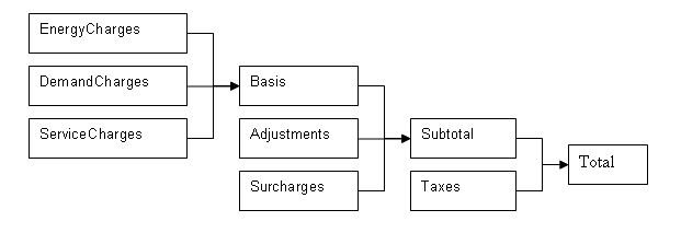
Figure 143. Hierarchy for Economics Charges
Any charges included in the EnergyCharges category are added together. The EnergyCharges, DemandCharges and ServiceCharges are added together to form the Basis. The Basis, Adjustments and Surcharges are added together to form the Subtotal. The Subtotal and Taxes are added together to be the Total. The total represents the total monthly charges on that tariff for the energy source used. The combining of categories together is performed automatically unless the user specifies the UtilityCost:Computation. In addition, each category, which is also a variable, may be used as a source. For example, a tax that is 5% of the subtotal would be shown as:
UtilityCost:Charge:Simple,
TaxOfFivePercent, ! Charge Variable Name
TariffExample1, ! Tariff Name
Subtotal, ! Source Variable
Annual, ! Season
Taxes, ! Category Variable Name
0.05; ! Cost Per Unit Value or Variable Name
As you can see, the UtilityCost:Charge:Simple and UtilityCost:Charge:Block objects do most of the “work” of computing the annual energy cost. The benefit of using this categorization is that totals of each category are shown in the output reports and it organizes the charges in the monthly calculations in a logical way that fits almost all tariffs. If no categorization is desired, theoretically, all charges could be assigned to the Total category. The categories themselves are simply variable names. Charges may also be assigned to the “NotIncluded” category if the result of the charge is used as an intermediate calculation and should not be included in the Total.
The rest of this section is divided into a reference of the objects and the fields, a set of examples, discussion of the reporting, and a description of Complex Tariff Modeling. For most tariffs, simply using a variety of UtilityCost:Charge:Simple’s and UtilityCost:Charge:Block’s will result in a good model but for some more complex tariffs, especially ones with complex block sizes, variables may be computed using a very simple programming language that may appear in the UtilityCost:Computation object. This will be described more in the Complex Tariff Modeling section.
Defines the name of the tariff, the type of tariff, and other details about the overall tariff. Each other object that is part of the tariff model references the tariff name including the UtilityCost:Charge:Simple, UtilityCost:Charge:Block, UtilityCost:Ratchet, UtilityCost:Qualify, UtilityCost:Variable and UtilityCost:Computation objects.
Multiple UtilityCost:Tariff objects can appear in the same IDF file. It is common that electric and gas utilities have more than one rate that may be used. Only one UtilityCost:Tariff for each Report Meter and Group Name is shown in the Economics Summary Report. The one that is shown in that report is chosen by first eliminating UtilityCost:Tariff objects that are not qualified due to their UtilityCost:Qualify objects. If more than one UtilityCost:Tariff object remains, the one that has the lowest cost for a combination of Report Meter and Group Name will be selected. If the Group Name field is not used, then the lowest cost UtilityCost:Tariff is chosen for each Report Meter.
Part of the tariff description is used to transform the annual energy use of any fuel under any meter into a group of named variables containing the values for each of the periods that the bills are calculated (usually monthly). The schedules create a variable for energy use and for demand. If specified it also creates a variable for energy and a variable for demand for the “on-peak”, “off-peak”, and “shoulder” periods for use in time-of-use tariffs. It performs this allocation prior to other calculations for the tariff. The variables that are always created are:
n totalEnergy
n totalDemand
The name of the tariff. Tariffs are sometimes called rates. The name is used in identifying the output results and in associating all of the charges and other objects that make up a tariff.
The name of any meter defined but usually set to either Electricity:Facility or Gas:Facility.
A choice that allows several different predefined conversion factors to be used; otherwise, user defined conversion factors are used as defined in the next two fields.
n UserDefined
n kWh
n Therm
n MMBtu
n MJ
n KBtu
n MCF
n CCF
The following table shows the conversion factors when specifying one of the predefined choices:
Table 36. Built in UtilityCost:Tariff Conversion Factors
|
Choice |
Energy Conversion Factor |
Demand Conversion Factor |
|
kWh |
0.0000002778 |
0.001 |
|
Therm |
9.4781712E-09 |
0.00003412 |
|
MMBtu |
9.4781712E-10 |
0.000003412 |
|
MJ |
0.000001 |
0.0036 |
|
KBtu |
9.4781712E-07 |
0.003412 |
|
MCF |
9.4781712E-10 |
0.000003412 |
|
CCF |
9.4781712E-09 |
0.00003412 |
Is a multiplier used to convert energy into the units specified by the utility in their tariff. If left blank, it defaults to 1 (no conversion). This field will be used only if Conversion Factor Choice is set to UserDefined. Within EnergyPlus energy always has units of J (joules). For conversion from J to kWh use the value of 0.0000002778. This is also used for all objects that reference the UtilityCost:Tariff.
Is a multiplier used to convert demand into the units specified by the utility in their tariff. If left blank, it defaults to 1 (no conversion). This field will be used only if Conversion Factor Choice is set to UserDefined. Within EnergyPlus demand always has units of J/s (joules/sec) which equivalent to W (watts). For conversion from W to kW use the value of 0.001. This is also used for all objects that reference the UtilityCost:Tariff.
The name of the schedule that defines the time-of-use periods that occur each day. The period schedule is used to determine which variables are defined. The values for the different variables are:
n 1 is Peak
n 2 is Shoulder
n 3 is OffPeak
n 4 is MidPeak
The following variables are created automatically if these different periods are used in the schedule and include:
n peakEnergy
n peakDemand
n shoulderEnergy
n shoulderDemand
n offPeakEnergy
n offPeakDemand
n midPeakEnergy
n midPeakDemand
Some special variables are created that include only demand from one period that exceeds the demand from another period. For other months that do not exceed, the values are zero. These variables are seldom used but are available for the occasional rate that includes a clause looking at demands during one period that exceed another period.
n PeakExceedsOffPeak
n OffPeakExceedsPeak
n PeakExceedsMidPeak
n MidPeakExceedsPeak
n PeakExceedsShoulder
n ShoulderExceedsPeak
If no Period Schedule is specified then no peak, offPeak, midPeak or shoulder variables are defined.
The name of a schedule that defines the seasons. The seasons are
n 1 is Winter
n 2 is Spring
n 3 is Summer
n 4 is Autumn
The change in the season schedule must occur at the same time as the change in the Monthly Schedule. In other words, a season must end at the same time as a billing month. Variables are automatically created if a season schedule is used. These variables are set to 1 within the season and 0 for the months that are not in the season. The variables are:
n isWinter
n isNotWinter
n isSpring
n isNotSpring
n isSummer
n isNotSummer
n isAutumn
n isNotAutumn
The name of the schedule that defines the billing periods of the year. Normally this entry is allowed to default and a schedule will be internally used that has the breaks between billing periods occurring at the same time as the breaks between months, i.e., at midnight prior to the first day of the month. If other billing periods are used such as two month cycles or a single bill for an entire season, such as some natural gas companies do in the summer, then the month schedule may be used to redefine it. Make sure that the month schedule and season schedule are consistent, otherwise an error will be issued.
n 1 is the first month, usually January
n 2 is the second month, usually February
n 3 is the third month, usually March
n 4 is the fourth month, usually April
n 5 is the fifth month, usually May
n 6 is the sixth month, usually June
n 7 is the seventh month, usually July
n 8 is the eighth month, usually August
n 9 is the ninth month, usually September
n 10 is the tenth month, usually October
n 11 is the eleventh month, usually November
n 12 is the twelfth month, usually December
Thus, the schedule that represents this would look like the following. If no schedule is specified the following Month Schedule is used which defines the months of the year as the normal calendar months.
Schedule:Compact, defaultMonths, number,
Through: 1/31, For: AllDays, Until: 24:00, 1,
Through: 2/28, For: AllDays, Until: 24:00, 2,
Through: 3/31, For: AllDays, Until: 24:00, 3,
Through: 4/30, For: AllDays, Until: 24:00, 4,
Through: 5/31, For: AllDays, Until: 24:00, 5,
Through: 6/30, For: AllDays, Until: 24:00, 6,
Through: 7/31, For: AllDays, Until: 24:00, 7,
Through: 8/31, For: AllDays, Until: 24:00, 8,
Through: 9/30, For: AllDays, Until: 24:00, 9,
Through: 10/31, For: AllDays, Until: 24:00, 10,
Through: 11/30, For: AllDays, Until: 24:00, 11,
Through: 12/31, For: AllDays, Until: 24:00, 12;
The determination of demand can vary by utility. Some utilities use the peak instantaneous demand measured but most use a fifteen minute average demand or a one hour average demand. Some gas utilities measure demand as the use during the peak day or peak week. The choices for demand window are:
n QuarterHour
n HalfHour
n FullHour
n Day
n Week
If no value is entered, QuarterHour is assumed. The choice may be overridden based on the value of Timestep so that they are consistent. If the Timestep is 6, i.e. 10 minute timesteps, then QuarterHour is not used and instead HalfHour is used instead. If Timestep is 3, i.e. 20 minute timesteps, then QuarterHour and HalfHour are not used and instead FullHour is used instead. Day and Week are primarily used by fuel utilities.
The fixed monthly service charge that many utilities have. The entry may be numeric and gets added to the ServiceCharges variable or if a variable name is entered here, its values for each month are used.
The minimum total charge for the tariff or if a variable name is entered here, its values for each month are used. The sum of the subtotal and taxes usually equals the total unless you have specified the minimum monthly charge. If the minimum monthly charge does not apply to the entire bill, a UtilityCost:Computation object can be specified using a Minimum function for the appropriate variables.
Used with real time pricing rates. The name of a schedule that contains the cost of energy for that particular time period of the year. Real time rates can be modeled using a charge schedule with the actual real time prices entered in the schedule. The charges should be consistent with the conversion factor specified in the tariff.
Used with real time pricing rates and often described as the CBL or customer baseline load. The name of a schedule that contains the baseline energy use for the customer. Many real time rates apply the charges as a credit or debit only to the difference between the baseline use and the actual use. The baseline use is established between the customer and the utility using a contract. If this field is used the baseline use schedule will be used for establishing the totalEnergy and totalDemand instead of the metered value and the real time rate charge is added or subtracted to the rate calculation using the real time charge schedule. If this field is not used, the real time charge schedule applies to all energy from the meter and totalEnergy and totalDemand is based on metered value as usual.
The group name of the tariff such as distribution, transmission, supplier, etc. If more than one tariff with the same group name is present and qualifies, only the lowest cost tariff is used. Usually the group name field is left blank which results in all tariffs using the same meter variable being compared and the lowest cost one being selected.
Sets whether the tariff is used for buying, selling or both to the utility. This should be allowed to default to BuyFromUtility unless a power generation system is included in the building that may generate more power than the building needs during the year. The choices are:
n BuyFromUtility – The values from the metered variable are used and are shown as being purchases from the utility.
n SellToUtility – The values from the metered variable are used for a “sell back” rate to the utility. The charges in the rate should be expressed as negative values.
n NetMetering – Negative values are used to reduce any positive values during the specific period on the tariff when negative values occur.
A warning will be issued if the selection of this field does not match the type of report meter.
Many utilities provide a large number of tariffs and separate their customers by the amount of energy use they have or by the amount of demand. The qualify object allows only certain tariffs that are modeled to be used. If the results of the simulation fall outside of the range of qualifications, that tariff is still calculated but the “Qualified” entry will say “No” and the UtilityCost:Qualify that caused its exclusion is shown. When multiple tariffs from the same utility are modeled and only one of them should be used, make sure that the qualifiers are consistent especially within the same GroupName (see UtilityCost:Tariff). Multiple UtilityCost:Qualify objects can appear for a specific rate and they can be based on any variable.
The energy used and demands for each month vary. Since it is possible that they vary across the minimum and maximum values defined by this object, a choice in how to treat the thresholds is necessary. Say that a utility has two tariffs, a small tariff that has a maximum demand requirement of 50kW and a large tariff that has a minimum demand requirement of 50kW. If the use for a building goes above the 50kW threshold during some summer months and the rest of the time is below 50kW, then how does the utility choose which rate would qualify. The utility probably has very specific requirements about which months or consecutive months can be above or below a threshold to qualify for the rate.
The name used for the UtilityCost:Qualify and displayed if the tariff does not qualify. It is also treated as a variable and contains:
n 1 for each month that does qualify,
n 0 for months that do not qualify, and
n -1 for months that are not part of the season selected.
The name of the UtilityCost:Tariff object that is associated with this UtilityCost:Qualify object.
The name of the variable used. For energy and demand, the automatically created variables, totalEnergy and totalDemand should be used, respectively.
Enter either “Minimum” or “Maximum”.
The minimum or maximum value for the qualify. If the variable has values that are less than this value when the qualify type is minimum then the tariff may be disqualified. If the variable has values that are greater than this value when the qualify type is maximum then the tariff may be disqualified. For demand, it is still the minimum of the demands set each month even though the demands are, by definition, the peak value for the month. Depending on the threshold test entry (see below) this minimum applies to all months, some of the months, or just a single month.
If the UtilityCost:Qualify only applies to a season, enter the season name from the following list:
n Annual
n Winter
n Spring
n Summer
n Fall
If this field is left blank, it defaults to Annual.
Enter either “Count” or “Consecutive”. Uses the number in Number of Months in one of two different ways depending on the Threshold Test. If the Threshold Test is set to “Count” then the qualification is based on the count of the total number of months per year. If the Threshold Test is set to “Consecutive” then the qualification is based on a consecutive number of months. If left blank this field defaults to count and it should be allowed to default for most cases.
A number from 1 to 12. If no value entered, 12 is assumed when the qualify type is minimum and 1 when the qualify type is maximum. This is the number of months that the threshold test applies to determine if the rate qualifies or not. If the season is less than 12 months (if it is not annual) then the value is automatically reduced to the number of months of the season.
The UtilityCost:Charge:Simple is one of the most often used objects for tariff calculation. It is used to compute energy and demand charges that are very simple. It may also be used for taxes, surcharges and any other charges that occur on a utility bill. As many UtilityCost:Charge:Simple objects as needed may be defined for a single tariff and they will be added together.
This is the name associated with the UtilityCost:Charge:Simple object and will appear in the report. In addition, the results of the UtilityCost:Charge:Simple calculation are stored in a variable with the same name. That way, the results may be used for further calculation. Spaces are not significant in Charge Variable Names. They are removed during the utility bill calculation process.
The name of the tariff that this UtilityCost:Charge:Simple is associated with.
The name of the source used by the UtilityCost:Charge:Simple. This is usually the name of the variable holding the energy or demand but may also be the name of any variable including the subtotal or basis if other charges are based on those.
This is the name (or number) of a season for which the UtilityCost:Charge:Simple is calculated. If this is set to Annual, the calculations are performed for the UtilityCost:Charge:Simple for the entire year (all months) otherwise it is calculated only for those months in the season defined. The season is defined by the Season Schedule in the UtilityCost:Tariff object. The choices for seasons are the following names or numbers may be used:
n Annual
n Winter
n Spring
n Summer
n Fall
All charges get added somewhere in the hierarchy described in the introduction to EnergyPlus economics above. This field shows where the charge should be added. The reason to enter this field appropriately is so that the charge gets reported in a reasonable category. The charge automatically gets added to the variable that is the category. The choices for this field are limited to:
n EnergyCharges
n DemandCharges
n ServiceCharges
n Basis
n Adjustment
n Surcharge
n Subtotal
n Taxes
n Total
n NotIncluded
This field contains either a single number or the name of a variable. The number is multiplied with all of the energy or demand or other source that is specified in the source field. If a variable is used, then the monthly values of the variable are multiplied against the variable specified in the source field. This field makes it easy to include a simple charge without specifying block sizes. It is added to any of the block calculations (see later fields) but is most often used by itself. If no value or variable is entered, a zero is assumed. This is a good way to include a tax or cost adjustment. For SellToUtility tariffs, the values in this field are usually expressed as negative numbers.
The UtilityCost:Charge:Block objects is also used extensively for tariff calculation. It is used to compute energy and demand charges that are structured in blocks of charges. It may also be used for taxes, surcharges and any other charges that occur on a utility bill but those are more commonly simple flat charges so UtilityCost:Charge:Simple is more commonly used for those functions. As many UtilityCost:Charge:Block objects as needed may be defined for a single tariff and they will be added together. Blocks are a structure used by almost all utilities for calculating energy and demand charges and they allow the utility to charge more or less per unit of energy or demand if more units are used.
This is the name associated with the UtilityCost:Charge:Block object and will appear in the report. In addition, the results of the UtilityCost:Charge:Block are stored in a variable with the same name. That way, the results may be used for further calculation.
The name of the tariff that this UtilityCost:Charge:Block is associated with.
The name of the source used by the UtilityCost:Charge:Block. This is usually the name of the variable holding the energy or demand but may also be the name of any variable including the subtotal or basis if other charges are based on those.
This is the name (or number) of a season for which the UtilityCost:Charge:Block is calculated. If this is set to annual, the calculations are performed for the UtilityCost:Charge:Block for the entire year (all months) otherwise it is calculated only for those months in the season defined. The season is defined by the Season Schedule in the UtilityCost:Tariff object. The choices for seasons are the following names or numbers may be used:
n Annual
n Summer
n Winter
n Spring
n Fall
All charges get added somewhere in the hierarchy described in the introduction to EnergyPlus economics above. This field shows where the charge should be added. The reason to enter this field appropriately is so that the charge gets reported in a reasonable category. The charge automatically gets added to the variable that is the category. The choices for this field are limited to:
n EnergyCharges
n DemandCharges
n ServiceCharges
n Basis
n Adjustment
n Surcharge
n Subtotal
n Taxes
n Total
n NotIncluded
If the blocks do not use all of the energy or demand from the source, some energy and demand remains, then the remaining amount should be assigned to a variable. If no variable is assigned and some amount of energy or demand is not used in the block structure a warning will be issued.
The sizes of the blocks are usually used directly but if a value or a variable is entered here, the block sizes entered in the rest of the charge are first multiplied by the entered value prior to being used. This is common for rates that are kWh/kW rates and in that case the variable that holds the monthly total electric demand would be entered. If no value is entered, a default value of one is assumed so that the block sizes remain exactly as entered. This field is unusual for the EnergyPlus syntax because it can be either a number or a name of a variable.
The size of the first block of the charges is entered here. For most rates that use multiple blocks, this will be the value for the first block size. Additional block sizes are entered with every other field. A default variable named “remaining” contains a large value and this may be used when the remaining amount should be included in that block. This field and the next field may be repeated in groups of two for as many blocks as are defined. This field is unusual for the EnergyPlus syntax because it can be either a number or a name of a variable.
The cost of the first block. This value is also repeated for every other field in the charge. As many blocks may be entered as are needed. This field and the previous field may be repeated in groups of two for as many blocks as are defined. This field is unusual for the EnergyPlus syntax because it can be either a number or a name of a variable. For SellToUtility tariffs, the values in this field are usually expressed as negative numbers.
These last two fields may be repeated fifteen times. If more blocks are defined by the utility, the computation can be continued using another UtilityCost:Charge:Block and using the variable from Remaining Into Variable as the source variable.
The UtilityCost:Ratchet command allows the modeling of tariffs that include some type of seasonal ratcheting. Ratchets are most common when used with electric demand charges. A ratchet is when a utility requires that the demand charge for a month with a low demand may be increased to be more consistent with a month that set a higher demand charge.
While the details of the UtilityCost:Ratchet command are described further in this section, an example is probably the easiest way to learn the basic functions.
Ratchet Example: A utility has a single ratchet that says that the billing demand for each month of the year is the higher value of the actual demand or 60% of the peak summer demand
UtilityCost:Ratchet,
BillingDemand1, ! Ratchet Variable Name
ExampleTariff1, ! Tariff Name
TotalDemand, ! Baseline Source Variable
TotalDemand, ! Adjustment Source Variable
Summer, ! Season From
Annual, ! Season To
0.60, ! Multiplier Value or Variable Name
0; ! Offset Value or Variable Name
The Ratchet Variable Name (the first field) should be used wherever the ratchet should be applied and is often the source variable for UtilityCost:Charge:Simple or UtilityCost:Charge:Block.
The detailed steps taken for the ratchet are the following:
n AdjSeasonal contains either:
n When SeasonFrom is not set to Monthly, the maximum for all months in Season From in the Adjustment Source Variable. This is a single value.
n When SeasonFrom is set to Monthly, the monthly values of the Adjustment Source Variable.
n AdjPeak = (AdjSeasonal + Offset) * Multiplier
n MaxAdjBase = maximum value of either AdjPeak or Baseline Source Variable
n The resulting Ratchet Variable contains:
n For months not in SeasonTo, the values of Baseline Source Variable
n For months in SeasonTo, the values of MaxAdjBase
If multiple ratchets occur in the same tariff, multiple UtilityCost:Ratchet commands should be “chained” together with the Baseline Source Variable subsequent ratchets referencing the Ratchet Variable Name of the previous UtilityCost:Ratchet.
Since the ratchet command can add together two variables, mutliply two variables, or take the maximum value between two variables, it may be used for other difficult to model tariffs without needing to use UtilityCost:Computation. Clever use of UtilityCost:Ratchet should be well documented with comments.
The name of the ratchet and the name of the result of this single ratchet.
The name of the tariff that this UtilityCost:Ratchet is associated with.
The name of the variable used as the baseline value. When the ratcheted value exceeds the baseline value for a month the ratcheted value is used but when the baseline value is greater then the ratcheted value the baseline value is used. Usually the electric demand charge is used. The baseline source variable can be the results of another ratchet object. This allows utility tariffs that have multiple ratchets to be modeled.
The variable that the ratchet is calculated from. It is often but not always the same as the baseline source variable. The ratcheting calculations using offset and multiplier are using the values from the adjustment source variable. If left blank, the adjustment source variable is the same as the baseline source variable.
The name of the season that is being examined. The maximum value for all of the months in the named season is what is used with the multiplier and offset. This is most commonly Summer or Annual. When Monthly is used, the adjustment source variable is used directly for all months.
n Annual
n Winter
n Spring
n Summer
n Fall
n Monthly
The name of the season when the ratchet would be calculated. This is most commonly Winter. The ratchet only is applied to the months in the named season. The resulting variable for months not in the Season To selection will contain the values as appear in the baseline source variable.
n Annual
n Winter
n Spring
n Summer
n Fall
Often the ratchet has a clause such as “the current month demand or 90% of the summer month demand”. For this case a value of 0.9 would be entered here as the multiplier. This value may be left blank if no multiplier is needed and a value of one will be used as a default.
A less common strategy is to say that the ratchet must be all demand greater than a value, in this case an offset that is added to the demand may be entered here. If entered, it is common for the offset value to be negative representing that the demand be reduced. If no value is entered it is assumed to be zero and not affect the ratchet.
The UtilityCost:Variable object allows for the direct entry of monthly values into a variable.
The name of the variable.
The name of the tariff that is using the variable.
This field is used to indicate the kind of units that may be associated with the variable. It is used by IDF Editor to display the appropriate SI and IP units for the January through December values. The available options are shown below. If none of these options are appropriate, select Dimensionless which will have no unit conversion.
n Energy
n Demand
n Currency
n Dimensionless
An entry (up to 24 are available) of the monthly values of the variable. Normally 12 months are used for most utility rates and so 12 values should be entered. If any values are not entered, the value of the previous entry is used. This allows a variable that is constant for an entire year to be entered using only the first value.
The UtilityCost:Computation object lists a series of computations that are used to perform the bill calculation. The object is only used for complex tariffs that cannot be modeled any other way. For 95% of the utility tariffs, using UtilityCost:Computation is unnecessary and should be avoided. If the UtilityCost:Computation object is used, it must contain references to all objects involved in the rate in the order that they should be computed.
The name of the UtilityCost:Computation.
The name of the tariff that this UtilityCost:Charge:Simple is associated with.
The Compute Step fields contain a simple language that describes the steps used in the computation process similar to a programming language. If no entry is made to any Compute Step fields (as usually the case) a default method of computing the rates shall be used. Compute Step is described later in this section under Complex Tariff Modeling.
Remember, this object should be omitted for almost all tariffs.
One of the best ways to learn the details of EnergyPlus Economics is to see some example tariffs and how they translate into objects. To do this, several different rates of increasing complexity are shown in the following examples.
Another source of examples is the large set of tariff input objects provided with EnergyPlus in the macro data set file called “UtilityTariffObjects.imf” located in the “MacroDataSets” folder where EnergyPlus is installed. This file contains sets of objects that fully define tariffs for commercial customers from a collection of U.S. utility companies.
As an example of the simplest type of tariff.
Customer Charge: $2.51 per month
Energy Charge: 5.5342 cents/kWh
This tariff would use a single UtilityCost:Charge:Simple object. The monthly charge is part of the UtilityCost:Tariff object.
UtilityCost:Tariff,
ExampleA, ! Name
Electricity:Facility, ! Output Meter Name
kWh, ! Conversion Factor Choice
, ! Energy Conversion Factor
, ! Demand Conversion Factor
, ! Time of Use Period Schedule Name
, ! Season Schedule Name
, ! Month Schedule Name
, ! Demand Window Length
2.51; ! Monthly Charge or Variable Name
UtilityCost:Charge:Simple,
FlatEnergyCharge, ! Charge Variable Name
ExampleA, ! Tariff Name
totalEnergy, ! Source Variable
Annual, ! Season
EnergyCharges, ! Category Variable Name
0.055342; ! Cost Per Unit Value or Variable Name
Another simple type of tariff is one where the energy charges vary by the amount of energy consumed each month.
Customer Charge: $5.75 per month
Energy Charge: 7.231 cents/kWh for first 200 kWh
6.656 cents/kWh for next 1000 kWh
5.876 cents/kWh for over 1200 kWh
This tariff would use a single UtilityCost:Charge:Block object. The monthly charge is part of the UtilityCost:Tariff object. Note that the block sizes are every other field at the bottom of the object and the that final block size references a built in variable called “remaining” that contains a very large number.
UtilityCost:Tariff,
ExampleB, ! Name
Electricity:Facility, ! Output Meter Name
kWh, ! Conversion Factor Choice
, ! Energy Conversion Factor
, ! Demand Conversion Factor
, ! Time of Use Period Schedule Name
, ! Season Schedule Name
, ! Month Schedule Name
, ! Demand Window Length
5.75; ! Monthly Charge or Variable Name
UtilityCost:Charge:Block,
BlockEnergyCharge, ! Charge Variable Name
ExampleB, ! Tariff Name
totalEnergy, ! Source Variable
Annual, ! Season
EnergyCharges, ! Category Variable Name
, ! Remaining Into Variable
, ! Block Size Multiplier Value or Variable Name
200, ! Block Size 1 Value or Variable Name
0.07231, ! Block 1 Cost per Unit Value or Variable Name
1000, ! Block Size 2 Value or Variable Name
0.06656, ! Block 2 Cost per Unit Value or Variable Name
remaining, ! Block Size 3 Value or Variable Name
0.05876; ! Block 3 Cost per Unit Value or Variable Name
This example contains both a block for energy and a block for demand and is very similar to the previous example except it now includes demand charges as well. The energy and demand charges vary by the amount of energy and demand consumed each month.
Energy Charge: 4.74 cents/kWh for first 20,000 kWh
4.24 cents/kWh for next 180,000 kWh
3.83 cents/kWh for additional kWh
Demand Charge: 5.38 dollars per kW for first 20 kW
4.23 dollars per kW for next 80 kW
3.60 dollars per kW for additional kW
This tariff would use two UtilityCost:Charge:Block objects. No monthly charge is shown so the UtilityCost:Tariff object can include just the first four fields. Note that the block sizes are every other field at the bottom of the object and the that final block size references a built in variable called “remaining” that contains a very large number.
UtilityCost:Tariff,
ExampleC, ! Name
Electricity:Facility, ! Output Meter Name
KWh; ! Conversion Factor Choice
UtilityCost:Charge:Block,
BlockEnergyCharge, ! Charge Variable Name
ExampleC, ! Tariff Name
totalEnergy, ! Source Variable
Annual, ! Season
EnergyCharges, ! Category Variable Name
, ! Remaining Into Variable
, ! Block Size Multiplier Value or Variable Name
20000, ! Block Size 1 Value or Variable Name
0.0474, ! Block 1 Cost per Unit Value or Variable Name
180000, ! Block Size 2 Value or Variable Name
0.0424, ! Block 2 Cost per Unit Value or Variable Name
remaining, ! Block Size 3 Value or Variable Name
0.0383; ! Block 3 Cost per Unit Value or Variable Name
UtilityCost:Charge:Block,
BlockDemandCharge, ! Charge Variable Name
ExampleC, ! Tariff Name
totalDemand, ! Source Variable
Annual, ! Season
DemandCharges, ! Category Variable Name
, ! Remaining Into Variable
, ! Block Size Multiplier Value or Variable Name
20, ! Block Size 1 Value or Variable Name
5.38, ! Block 1 Cost per Unit Value or Variable Name
80, ! Block Size 2 Value or Variable Name
4.23, ! Block 2 Cost per Unit Value or Variable Name
remaining, ! Block Size 3 Value or Variable Name
3.60; ! Block 3 Cost per Unit Value or Variable Name
Another type of tariff is one where the energy charges vary by the amount of energy consumed each month and are different for the summer and winter. In addition, this example demonstrates the minimum charge field.
Minimum Charge: $7.00 per month
Winter – October through May
Energy Charge: 4.385 cents/kWh for first 650 kWh
3.763 cents/kWh for next 350 kWh
3.704 cents/kWh for over 1000 kWh
Summer – June through September
Energy Charge: 8.385 cents/kWh for first 650 kWh
7.588 cents/kWh for next 350 kWh
7.103 cents/kWh for over 1000 kWh
This tariff would use two UtilityCost:Charge:Block objects. The monthly charge is part of the UtilityCost:Tariff object. Note that the block sizes are every other field at the bottom of the object and the that final block size references a built in variable called “remaining” that contains a very large number.
UtilityCost:Tariff,
ExampleD, ! Name
Electricity:Facility, ! Output Meter Name
KWh, ! Conversion Factor Choice
, ! Energy Conversion Factor
, ! Demand Conversion Factor
, ! Time of Use Period Schedule Name
TwoSeasonSchedule, ! Season Schedule Name
, ! Month Schedule Name
, ! Demand Window Length
, ! Monthly Charge or Variable Name
7.00; ! Minimum Monthly Charge or Variable Name
UtilityCost:Charge:Block,
WinterEnergyCost, ! Charge Variable Name
ExampleD, ! Tariff Name
totalEnergy, ! Source Variable
Winter, ! Season
EnergyCharges, ! Category Variable Name
, ! Remaining Into Variable
, ! Block Size Multiplier Value or Variable Name
650, ! Block Size 1 Value or Variable Name
0.04385, ! Block 1 Cost per Unit Value or Variable Name
350, ! Block Size 2 Value or Variable Name
0.03763, ! Block 2 Cost per Unit Value or Variable Name
remaining, ! Block Size 3 Value or Variable Name
0.03704; ! Block 3 Cost per Unit Value or Variable Name
UtilityCost:Charge:Block,
SummerEnergyCost, ! Charge Variable Name
ExampleD, ! Tariff Name
totalEnergy, ! Source Variable
Summer, ! Season
EnergyCharges, ! Category Variable Name
, ! Remaining Into Variable
, ! Block Size Multiplier Value or Variable Name
650, ! Block Size 1 Value or Variable Name
0.08385, ! Block 1 Cost per Unit Value or Variable Name
350, ! Block Size 2 Value or Variable Name
0.07588, ! Block 2 Cost per Unit Value or Variable Name
remaining, ! Block Size 3 Value or Variable Name
0.07103; ! Block 3 Cost per Unit Value or Variable Name
Schedule:Compact, TwoSeasonSchedule, number,
Through: 5/31, For: AllDays, Until: 24:00, 1,
Through: 9/30, For: AllDays, Until: 24:00, 3,
Through: 12/31, For: AllDays, Until: 24:00, 1;
A more advanced rate varies the size of the blocks based on amount of demand for the month. This creates an effective demand charge if the blocks have declining values.
Customer Charge: $14.00 per month
Energy Charge: 8.756 cents/kWh for all consumption not greater than 200 hours times the demand
6.812 cents/kWh for all consumption in excess of 200 hours and not greater than 400 hours times the demand
5.029 cents/kWh for all consumption in excess of 400 hours times the demand.
This tariff would use a single UtilityCost:Charge:Block object. The monthly charge is part of the UtilityCost:Tariff object. In this case the Block Size Multiplier Value (or Variable) is set to the totalDemand variable.
UtilityCost:Tariff,
ExampleE, ! Name
Electricity:Facility, ! Output Meter Name
KWh, ! Conversion Factor Choice
, ! Energy Conversion Factor
, ! Demand Conversion Factor
, ! Time of Use Period Schedule Name
, ! Season Schedule Name
, ! Month Schedule Name
, ! Demand Window Length
14; ! Monthly Charge or Variable Name
UtilityCost:Charge:Block,
BlockEnergyCharge, ! Charge Variable Name
ExampleE, ! Tariff Name
totalEnergy, ! Source Variable
Annual, ! Season
EnergyCharges, ! Category Variable Name
, ! Remaining Into Variable
totalDemand, ! Block Size Multiplier Value or Variable Name
200, ! Block Size 1 Value or Variable Name
0.08756, ! Block 1 Cost per Unit Value or Variable Name
200, ! Block Size 2 Value or Variable Name
0.06812, ! Block 2 Cost per Unit Value or Variable Name
remaining, ! Block Size 3 Value or Variable Name
0.05029; ! Block 3 Cost per Unit Value or Variable Name
Tariffs sometimes have higher costs for energy consumed during the daytime than at night. This example includes energy charges that vary by the time of day and by the season.
Monthly Charge: $37.75 per month
Winter – October through May
On Peak: 8.315 cents/kWh
Off-Peak: 2.420 cents/kWh
Summer – June through September
On Peak: 14.009 cents/kWh
Off-Peak: 6.312 cents/kWh
The on-peak period is defined as the hours starting at 10am and ending at 7pm, Monday through Friday for June through September and 3pm to 10pm Monday through Friday for October through May. All other hours are considered off-peak.
The tariff is only applicable for customers that use 50KW for at least one month of the year.
This tariff uses four different UtilityCost:Charge:Simple objects to capture the variation with time of the energy cost. The monthly charge is part of the UtilityCost:Tariff object.
UtilityCost:Tariff,
ExampleF, ! Name
Electricity:Facility, ! Output Meter Name
kWh, ! Conversion Factor Choice
, ! Energy Conversion Factor
, ! Demand Conversion Factor
TimeOfDaySchedule, ! Time of Use Period Schedule Name
TwoSeasonSchedule, ! Season Schedule Name
, ! Month Schedule Name
, ! Demand Window Length
37.75; ! Monthly Charge or Variable Name
UtilityCost:Charge:Simple,
SummerOnPeak, ! Charge Variable Name
ExampleF, ! Tariff Name
peakEnergy, ! Source Variable
Summer, ! Season
EnergyCharges, ! Category Variable Name
0.14009; ! Cost per Unit Value or Variable Name
UtilityCost:Charge:Simple,
SummerOffPeak, ! Charge Variable Name
ExampleF, ! Tariff Name
offPeakEnergy, ! Source Variable
Summer, ! Season
EnergyCharges, ! Category Variable Name
0.06312; ! Cost per Unit Value or Variable Name
UtilityCost:Charge:Simple,
WinterOnPeak, ! Charge Variable Name
ExampleF, ! Tariff Name
peakEnergy, ! Source Variable
Winter, ! Season
EnergyCharges, ! Category Variable Name
0.08315; ! Cost per Unit Value or Variable Name
UtilityCost:Charge:Simple,
WinterOffPeak, ! Charge Variable Name
ExampleF, ! Tariff Name
offPeakEnergy, ! Source Variable
Winter, ! Season
EnergyCharges, ! Category Variable Name
0.02420; ! Cost per Unit Value or Variable Name
UtilityCost:Qualify,
MinDemand, ! Name
ExampleF, ! Tariff Name
TotalDemand, ! Variable Name
Minimum, ! Qualify Type
50, ! Threshold Value or Variable Name
Annual, ! Season
Count, ! Threshold Test
1; ! Number of Months
Schedule:Compact, TwoSeasonSchedule, number,
Through: 5/31, For: AllDays, Until: 24:00, 1,
Through: 9/30, For: AllDays, Until: 24:00, 3,
Through: 12/31, For: AllDays, Until: 24:00, 1;
Schedule:Compact, TimeOfDaySchedule, number,
Through: 5/31, For: AllDays, Until: 15:00, 3,
Until: 22:00, 1,
Until: 24:00, 3,
Through: 9/30, For: AllDays, Until: 10:00, 3,
Until: 19:00, 1,
Until: 24:00, 3,
Through: 12/31, For: AllDays, Until: 15:00, 3,
Until: 22:00, 1,
Until: 24:00, 3;
Utilities have come up with many different ways to encourage certain load factors and discourage other load factors. One method that has been used is blocks defined within other blocks. In the following example standard kWh blocks exist within the energy allocated for the first of several kWh/kW blocks.
Monthly Charge: $35 per month
Energy Charge: For all consumption not greater than 200 hours times the demand use
10.32 cents/kWh for the first 1000 kWh
7.43 cents/kWh for the next 4000 kWh
6.23 cents/kWh for the next 5000 kWh
4.27 cents/kWh for the remaining kWh less than 200 hours times the demand
6.82 cents/kWh for all consumption in excess of 200 hours and not greater than 400 hours times the demand
5.03 cents/kWh for all consumption in excess of 400 hours times the demand.
To set up this “block within a block” a UtilityCost:Charge:Block is first used to separate out the first 200 kWh/kW. The “EnergyFirst200kWhPerkW” charge performs this. It uses demand to multiply the first block size by 200 and the “cost” for the block is simply 1 since it passes through the energy to the variable “EnergyFirst200kWhPerkW”. The remaining energy goes into the “restOfEnergy” variable as specified as the “Remaining Into Variable” field. After this is evaluated we have two new variables that hold energy. Each of these variables are then separately used in UtilityCost:Charge:Block objects to evaluate the different parts of the example tariff. By using the “Remaining Into Variable” along with the concept of variables, many very complex tariffs may be modeled.
UtilityCost:Tariff,
ExampleG, !- Name
ElectricityPurchased:Facility, !- Output Meter Name
KWh, !- Conversion Factor Choice
, !- Energy Conversion Factor
, !- Demand Conversion Factor
, !- Time of Use Period Schedule Name
, !- Season Schedule Name
, !- Month Schedule Name
, !- Demand Window Length
35; !- Monthly Charge or Variable Name
UtilityCost:Charge:Block,
EnergyFirst200kWhPerkW, !- Charge Variable Name
ExampleG, !- Tariff Name
totalEnergy, !- Source Variable
Annual, !- Season
NotIncluded, !- Category Variable Name
restOfEnergy, !- Remaining Into Variable
totalDemand, !- Block Size Multiplier Value or Variable Name
200, !- Block Size 1 Value or Variable Name
1; !- Block 1 Cost Per Unit Value or Variable Name
UtilityCost:Charge:Block,
CostOfFirst200kWhPerkW, !- Charge Variable Name
ExampleG, !- Tariff Name
EnergyFirst200kWhPerkW, !- Source Variable
Annual, !- Season
EnergyCharges, !- Category Variable Name
, !- Remaining Into Variable
, !- Block Size Multiplier Value or Variable Name
1000, !- Block Size 1 Value or Variable Name
0.1032, !- Block 1 Cost Per Unit Value or Variable Name
4000, !- Block Size 2 Value or Variable Name
0.0743, !- Block 2 Cost Per Unit Value or Variable Name
5000, !- Block Size 3 Value or Variable Name
0.0623, !- Block 3 Cost Per Unit Value or Variable Name
remaining, !- Block Size 4 Value or Variable Name
0.0427; !- Block 4 Cost Per Unit Value or Variable Name
UtilityCost:Charge:Block,
CostOfRestOfEnergy, !- Charge Variable Name
ExampleG, !- Tariff Name
restOfEnergy, !- Source Variable
Annual, !- Season
EnergyCharges, !- Category Variable Name
, !- Remaining Into Variable
totalDemand, !- Block Size Multiplier Value or Variable Name
200, !- Block Size 1 Value or Variable Name
0.0682, !- Block 1 Cost Per Unit Value or Variable Name
remaining, !- Block Size 2 Value or Variable Name
0.0503; !- Block 2 Cost Per Unit Value or Variable Name
Some utilities have tariffs that can have different prices every hour of the year called Real Time Pricing tariffs. Often the utility will inform the customer of the prices for each hour of the day just one day in advance. To model this type of utility rate a normal schedule is used that contains the prices on an hourly basis. The “Charge Schedule” field is where the Schedule object containing the prices is referenced. In addition, the “Baseline Use Schedule” field is used to set the schedule for the customer baseline load. Not all utilities use a customer baseline load so the field can be left blank if none is needed. The Period, Season and Month Schedules are not needed for these tariffs unless UtilityCost:Charge’s are used. The Schedule:File object can be especially useful to input a complex schedule that changes throughout the year.
Example H, shown below, is an example of how to use the UtilityCost:Tariff object with a schedule to calculate a utility tariff using real time prices. The example real time pricing schedule results in the same energy cost as Example F – Seasonal Time of Use Energy. This is only an example and usually for real time pricing the schedule values would vary throughout the year.
! EXAMPLE H - Real Time Pricing (RTP)
UtilityCost:Tariff,
ExampleH, !- Name
ElectricityPurchased:Facility, !- Output Meter Name
kWh, !- Conversion Factor Choice
, !- Energy Conversion Factor
, !- Demand Conversion Factor
, !- Time of Use Period Schedule Name
, !- Season Schedule Name
, !- Month Schedule Name
, !- Demand Window Length
37.75, !- Monthly Charge or Variable Name
, !- Minimum Monthly Charge or Variable Name
RTPpriceSchedule-H, !- Real Time Pricing Charge Schedule Name
, !- Customer Baseline Load Schedule Name
, !- Group Name
buyFromUtility; !- Buy Or Sell
Schedule:Compact,
RTPpriceSchedule-H, !- Name
Any Number, !- Schedule Type Limits Name
Through: 5/31, !- Field 1
For: AllDays, !- Field 2
Until: 15:00, !- Field 3
0.02420, !- Field 4
Until: 22:00, !- Field 5
0.08315, !- Field 6
Until: 24:00, !- Field 7
0.02420, !- Field 8
Through: 9/30, !- Field 9
For: AllDays, !- Field 10
Until: 10:00, !- Field 11
0.06312, !- Field 12
Until: 19:00, !- Field 13
0.14009, !- Field 14
Until: 24:00, !- Field 15
0.06312, !- Field 16
Through: 12/31, !- Field 17
For: AllDays, !- Field 18
Until: 15:00, !- Field 19
0.02420, !- Field 20
Until: 22:00, !- Field 21
0.08315, !- Field 22
Until: 24:00, !- Field 23
0.02420; !- Field 24
When the building contains a generator, photovoltaics, or other sources of electrical power, there is an opportunity for the building generator to produce more power than the building uses. The excess power can either be sold to the utility or offset the energy purchased.
When the excess power is sold, two utility rates need to be defined. The first can be defined just as in any of the previous examples. Since the “Buy or Sell” field of the UtilityCost:Tariff object defaults to “buyFromUtility” it does not even need to be specified. The meter specified in the “Report Meter” is usually set to “ElectricityPurchased:Facility.”
The second tariff needs to be defined with the “Buy or Sell” field set to “sellToUtility.” The “Report Meter” is usually set to “ElectricitySurplusSold:Facility.” It is important to set the appropriate meters that correspond with the “Buy or Sell” field. The example below shows an tariff that sells the excess electricity back to utility. The UtilityCost:Charge:Simple object contains a “Cost Per Value” with a negative number. A negative number is critical if a credit for selling this electricity is expected.
! EXAMPLE I - Selling
UtilityCost:Charge:Simple,
GeneratedElectricSold, !- Charge Variable Name
ExampleI-Sell, !- Tariff Name
totalEnergy, !- Source Variable
Annual, !- Season
EnergyCharges, !- Category Variable Name
-0.02; !- Cost Per Unit Value (or Variable)
UtilityCost:Tariff,
ExampleI-Sell, !- Name
ElectricitySurplusSold:Facility, !- Output Meter Name
kWh, !- Conversion Factor Choice
, !- Energy Conversion Factor
, !- Demand Conversion Factor
, !- Time of Use Period Schedule Name
, !- Season Schedule Name
, !- Month Schedule Name
, !- Demand Window Length
, !- Monthly Charge or Variable Name
, !- Minimum Monthly Charge or Variable Name
, !- Real Time Pricing Charge Schedule Name
, !- Customer Baseline Load Schedule Name
, !- Group Name
sellToUtility; !- Buy Or Sell
UtilityCost:Charge:Simple,
GeneratedElectricSold, !- Charge Variable Name
ExampleI-Sell, !- Tariff Name
totalEnergy, !- Source Variable
Annual, !- Season
EnergyCharges, !- Category Variable Name
-0.02; !- Cost Per Unit Value or Variable Name
The next part of this example is a rate that uses net-metering. With net metering the meter conceptually turns backwards when the energy is being sold to the utility directly reducing the energy consumption being charged. Effectively, the rate charge for purchased electricity is the same as the rate credited for electricity sold to the utility. In this the “Buy or Sell” field should be set to “netMetering.” It is also important the “Report Meter” is set to a meter that represents net metering such as “ElectricityNet:Facility.” The following example shows a simple example tariff using net metering with a single UtilityCost:Charge:Simple:
! EXAMPLE I – Net Metering
UtilityCost:Tariff,
ExampleI-NetMeter, !- Name
ElectricityNet:Facility, !- Output Meter Name
kWh, !- Conversion Factor Choice
, !- Energy Conversion Factor
, !- Demand Conversion Factor
, !- Time of Use Period Schedule Name
, !- Season Schedule Name
, !- Month Schedule Name
, !- Demand Window Length
30.00, !- Monthly Charge or Variable Name
, !- Minimum Monthly Charge or Variable Name
, !- Real Time Pricing Charge Schedule Name
, !- Customer Baseline Load Schedule Name
, !- Group Name
netMetering; !- Buy Or Sell
UtilityCost:Charge:Simple,
NetMeteredCharge, !- Charge Variable Name
ExampleI-NetMeter, !- Tariff Name
totalEnergy, !- Source Variable
Annual, !- Season
EnergyCharges, !- Category Variable Name
0.065; !- Cost Per Unit Value or Variable Name
A standardized tabular output report is created which shows all components of all categories in the calculation sequence on a variable basis (usually 12 numbers, one for each month). The economics report is automatically created if any UtilityCost:Tariff objects are present. The values reported are in the units specified in the UtilityCost:Tariff object. The report includes:
n Annual Cost – Shows the annual cost for qualified and selected electric and gas tariffs and the total cost
n Tariff Summary – For each tariff included shows if that tariff was selected, if it was qualified, what meter it was connected to, what group it was part of, and the annual cost. The qualified tariff with the lowest annual cost for each of the meters is indicated as “selected” and shown in the Annual Cost section of the report. If multiple groups are defined, a tariff is selected from each group.
Tariff Summary
n Summary table – Shows the if that tariff was selected, if it was qualified, which qualifier disqualified the tariff, what meter it was connected to, what group it was part of, if the computation was based on a user defined computation or was automatic.
n Categories – Shows the monthly results of all the category variables.
n Charges – Shows the monthly results for all of the simple and block charges.
n Ratchets – Shows the monthly results for all ratchets.
n Qualifies – Shows the monthly results for all qualifies.
n Native Variables – Shows the monthly values for the native variables such as TotalEnergy and TotalDemand.
n Other Variables – Shows the monthly values for any other variables not appearing in the other tables.
n Computation – Shows the computational steps used including those generated automatically.
The report is part of the tabular report and is created using the same style as specified for the tabular reports.
Much can be accomplished with the UtilityCost:Charge:Simple and UtilityCost:Charge:Block objects. In almost all cases, these structures are flexible enough to model the tariff. At times the built in approach is not sufficient to model a particular rate. In those cases, the rate may be modeled by using the UtilityCost:Computation object. For most rates this object can be omitted but for difficult to model rates, they may be used to modify the normal way the rate computation is performed.
Each ComputeStep is performed in order and can be either a variable followed by an expression or simply a variable.
n demandMod SUM demand1 demand2
n chargeSummer1
The normal calculations associated with the UtilityCost:Qualify, UtilityCost:Charge:Simple, UtilityCost:Charge:Block, or UtilityCost:Ratchet are performed the first time that object is called. Subsequent times are not recomputed but use the value stored in the appropriate variable. The result of the computation for those objects is available in the expression for further computation. The expressions allow the manipulation of variables directly using simple mathematical functions. Only variable names may be entered along with operators. Numbers may not be entered and should be entered with UtilityCost:Variable. Multiple operators are allowed per step. Variables names do not include spaces. If spaces are found in a variable name then an error is shown. Unused variables are flagged with a warning. All expressions are in the form:
n assignedToVariable OPERATOR variable1 variable2
Each step is performed for each of the months before the next step is taken. The same operation is performed for each step as specified.
The actual evaluation of the expression is performed from the end of the line to the beginning using stack based operations. Some operators pull all values from the stack (SUM, MAXIMUM, MINIMUM) while most use just one or two values from the stack. All operations return a single value to the stack. This stack based approach to expressions is sometimes called Polish Notation. While multiple operators are allowed per line, it reduces confusion if each line has only a single operator.
When the UtilityCost:Computation object is used, it must contain references to all objects involved in the rate in the order that they should be computed. No checking is performed for objects that should or should not be included; instead, the computational process is driven completely by the input of this object.
A typical rate will have a simple series of steps. For example F the following steps would be created automatically by the software:
UtilityCost:Computation,
SpecialStepsForF, !- Name
ExampleF, !- Tariff Name
EnergyCharges SUM SummerOnPeak SummerOffPeak WinterOnPeak WinterOffPeak, Compute Step 1
Basis SUM EnergyCharges DemandCharges ServiceCharges, Compute Step 2
SubTotal SUM Basis Adjustments Surcharges, Compute Step 3
Total SUM SubTotal Taxes, Compute Step 4
MinDemand; Compute Step 5
This example does not have any dependency of different charges that are summed on the same line but if it did the charges could appear by themselves on lines and this would indicate the order that they should be computed. Here is the same example again showing that form.
UtilityCost:Computation,
SpecialStepsForF, !- Name
ExampleF, !- Tariff Name
SummerOnPeak, !- Compute Step 1
SummerOffPeak, !- Compute Step 2
WinterOnPeak, !- Compute Step 3
WinterOffPeak, !- Compute Step 4
EnergyCharges SUM SummerOnPeak SummerOffPeak WinterOnPeak WinterOffPeak, !- Compute Step 5
Basis SUM EnergyCharges DemandCharges ServiceCharges, !- Compute Step 6
SubTotal SUM Basis Adjustments Surcharges, !- Compute Step 7
Total SUM SubTotal Taxes, !- Compute Step 8
MinDemand; !- Compute Step 9
This second expanded format is generated automatically when no UtilityCost:Computation object is provided.
The functions built in are (number of arguments in parentheses):
Adds together all of the variable values for each month for as many variables that are used.
Adds together the first variable value with the second variable value.
Multiplies the first variable value with the second variable value. MULT may also be used.
Subtracts the second variable value from the first variable value. SUBT may also be used.
Divides the first variable value by the second variable value. DIV may also be used.
Takes the absolute value of the variable value. This turns negative values into positive ones. ABS may also be used.
Removes non-integer portions of the variable values. INT may also be used.
Returns a 1 for positive values, -1 for negative values and 0 for zero values.
Selects the maximum value across variables for each of the months. Two or more variables may be used. MAX may also be used.
Selects the minimum value across variables for each of the months. Two or more variables may be used. MIN may also be used.
Returns the difference between the first and second variable if the first variable is greater than the second. If the second variable is greater or equal to the first variable returns a zero.
Returns the minimum value of the twelve months in the variable. Zero values are ignored (see also ANNUALMINZERO). If all values are zero then zero is returned. ANMIN may also be used.
Returns the maximum value of the twelve months in the variable. Zero values are ignored (see also ANNUALMAXZERO). If all values are zero then zero is returned. ANMAX may also be used.
Returns the sum of the twelve months in the variable. ANSUM may also be used.
Returns the sum of the twelve monthly values divided by the number of non-zero monthly values. If all values are zero than zero is returned. If an average is desired that includes zero valued elements the SUM() function should be used divided by 12. ANAVG may also be used.
Returns 1 for all monthly values if any of the monthly values are non-zero. ANOR may also be used.
Returns 1 for all monthly values if all of the monthly values are non-zero. ANAND may also be used.
Returns the maximum value of the twelve monthly values in x. Zeros are counted so if a zero is the largest value (the rest would be negative) a zero may be returned. ANMAXZ may also be used.
Returns the minimum value of the twelve monthly values in x. Zeros are counted. ANMINZ may also be used.
Returns the value of the second variable if the first variable is non-zero otherwise returns the value of the third variable. Usually used with GT, GE, LT, LE, EQ, NE operators.
1 if the first variable value is greater than the second variable value otherwise 0. GT may also be used.
1 if the first variable value is greater than or equal to the second variable value otherwise 0. GE may also be used.
1 if the first variable value is less than the second variable value otherwise 0. LT may also be used.
1 if the first variable value is less than or equal to the second variable value otherwise 0. LE may also be used.
1 if the first variable value is equal to the second variable value otherwise 0. EQ may also be used.
1 if the first variable value is not equal to the second variable value otherwise 0. NE may also be used.
1 if the first variable value and second variable values are both not zero otherwise 0.
1 if the first variable value and second variable values are either not zero, otherwise 0 if both the first and second variable value are both zero.
1 if the first variable value and only variable value is zero otherwise 0 if the first variable value is not zero.
Indicates what variables a variable is dependant on (or derived from). No computation is performed. The algorithm that creates the automatic sequence of equations uses these to indicate when variables are dependant on other variables so that they can be sorted into the correct order.
In order to understand how to include cost estimates, it may be helpful to first define some terminology and provide an overview of the process used in EnergyPlus. There are three broad steps involved. The first involves determining construction costs by summing individual “line items.” The second involves determining project costs by adjusting construction costs to account for things like profit and design fees. The third involves comparing the current simulation to a reference case so that marginal increases can be calculated. Each of these steps involves using one of the three ‘ComponentCost’ objects described below.
Each instance of this object creates a cost line item and will contribute to the total for a cost estimate. Each line item is reported in table form in the tabular report file. The user must request that this report be generated by including a Output:Table:SummaryReports object with the Component Cost Economics Summary option selected. The style of a tabular report can be controlled using the OutputControl:Table:Style object.
Cost estimates are not currently general in that they cannot be performed for every type of component that could be included in an EnergyPlus model. Although a “General” option is available where all information needed for the cost line item is input by the user, the usefulness of cost modeling within EnergyPlus is expected to be enhanced when quantities are obtained from elsewhere in the input file or computed during a simulation. The cost computations are programmed in selected ways for selected objects. The objects available and the type of cost modeling that may be performed are discussed in detail in the discussion of Reference Object Type field. A particular instance of this object will always have many blank fields. Entering values in too many fields may cause an error because the program may determine how a particular cost is to be calculated based on the presence of non-zero values in particular fields. The input object includes fields that are reserved for future use in expanded cost estimate and investment analyses planned for future versions of EnergyPlus. If you would like to request additional objects or different methods of modeling component costs, feel free to describe your needs and submit a request via email to energyplus-support@gard.com.
This field is a user-selected name that will appear in the line item description of the cost report. It is not used in the calculation but allows identifying a line item in the subsequent report.
This field is not yet used and may be left blank.
The cost estimate line item calculation will be controlled by the name entered in this field. The requirements for the remaining input, and the cost calculations performed, will vary depending on the object referenced here. Only selected objects can be entered here. The objects available for cost estimating are listed in the following table showing the active fields and options available for each.
Table 37. Cost Line Item Types (ref Objects)
|
Object Types available |
Cost per each |
Cost per m2 |
Cost per kW |
Cost per kW *COP |
Cost per m3 |
Cost per m3/s |
Cost per W/K |
Qty |
Wildcard for Name |
|
General |
X |
|
|
|
|
|
|
X |
|
|
Construction |
|
X |
|
|
|
|
|
|
|
|
Coil:DX |
X |
|
X |
X |
|
|
|
|
X |
|
Chiller:Electric |
X |
|
X |
X |
|
|
|
|
|
|
|
|
|
|
|
|
|
|
|
|
|
Coil:Heating:Gas |
X |
|
X |
X |
|
|
|
|
X |
|
Daylighting:Controls |
X |
|
|
|
|
|
|
|
X |
|
Shading:Zone:Detailed |
|
X |
|
|
|
|
|
|
|
|
Lights |
X |
|
X |
|
|
|
|
|
|
|
Generator:Photovoltaic |
|
|
X |
|
|
|
|
|
|
|
|
|
|
|
|
|
|
|
|
|
|
|
|
|
|
|
|
|
|
|
|
|
|
|
|
|
|
|
|
|
|
|
General
This choice of object is used to calculate costs in a general way. No quantities from internal calculations are used. All information needed for the cost line item is input by the user. The Cost per Each and the Quantity fields that follow need to have values.
This choice of object type is used to calculate the costs associated with surfaces based on the type of Construction used for the surface. Costs are entered on a per-square-meter basis. The program finds all the surfaces that have the type of Construction named in the Reference Object Name field that follows and determines the total area. If the model includes duplicate surfaces, as for interior partitions or floors, these will be detected and not double-counted. The cost per area should include all the material layers defined in the Construction.
This choice of object type is used to calculate the cost of direct expansion cooling equipment. Cost can be entered in three different ways, (1) per each, (2) per kW total cooling capacity, or (3) per kW total cooling capacity per COP (coefficient of performance). The program will determine which method to use by examining which input fields have non-zero values. It is an error to specify costs in more than one way. The per-each approach is most useful for discrete packages. The per-kW approach is useful for autosizing DX coils with the same COP. The per-kW-per-COP approach is convenient for modeling autosized DX coils with differing COPs as long as a linear relationship is sufficient.
The wildcard character “*” may be used in the object name field that follows to allow a single line item to include all of the DX coils in the model.
Chiller:Electric
This choice of object type is used to calculate the cost of a central chiller. The object name entered in following field must correspond to a Chiller:Electric object name defined elsewhere in the input file. Cost can be entered in three different ways, (1) per each, (2) per kW total cooling capacity or (3) per kW total cooling capacity per COP (coefficient of performance). The program will determine which method to use by examining which input fields have non-zero values. It is an error to specify costs in more than one way. The per-each approach is most useful for discrete chillers. The per-kW approach is useful for autosizing chillers with the same COP. The per-kW-per-COP approach is convenient for modeling autosized chillers with differing COPs as long as a linear relationship is sufficient.
This choice of object type is used to calculate the cost of gas-fired heating equipment. Cost can be entered in three different ways, (1) per each, (2) per kW of heating capacity, or (3) per kW total cooling capacity per nominal efficiency (actually uses the per kW per COP field). The program will determine which method to use by examining which input fields have non-zero values. It is an error to specify costs in more than one way. The per-each approach is most useful for discrete packages. The per-kW approach is useful for autosizing heating coils with the same efficiency. The per-kW-per-Eff approach is convenient for modeling autosized heating coils with differing efficiencies as long as a linear relationship is sufficient.
The wildcard character “*” may be used in the object name field that follows to allow a single line item to include all of the gas heating coils in the model.
These choices of object type are used to include the cost of controllers needed to control electric lighting in response to daylight. The only option for entering costs is “per each”. The wildcard character “*” may be used in the following object name field to allow a single line item to include all of the simple and detailed daylighting controls in the cost model.
This choice of object type is used to calculate the costs associated with attached shading surfaces. Costs are entered on a per-square-meter basis. The cost calculations are similar to those for heat transfer surfaces but are handled separately because “Construction” is not defined for a shading surface. The object name entered in the following field must correspond to a Shading:Zone:Detailed object name defined elsewhere in the input file.
This choice of object is used to calculate the costs associated with electric lighting. Costs are entered on either a cost-per-each basis or as a cost-per-kilowatt-of-design-level. (This design level is an input in the Lights object.). The object name entered into the following field must match the name of a Zone object defined elsewhere in the input file.
This choice of object is used to calculate the costs associated with a photovoltaic system. Costs are entered on a cost-per-kilowatt-of-rated-capacity. The rated capacity of a photovoltaic generator is calculated for cost modeling by exposing the surface to a 1000 W/m2 incident radiation using the area fraction and nominal fixed efficiency input by the user (from the Generator:Photovoltaic object). The object name entered into the following field must match the name of a Generator:Photovoltaic object defined elsewhere in the input file.
This field is used to refer to a specific instance of an object. The wildcard character “*” is acceptable for some objects as described above for the previous field.
This field is not yet used and may be left blank.
This field is used to enter cost information on a per-each basis. The units are dollars ($).
This field is used to enter cost information on a per-area basis. The units are dollars per square meter ($/m2).
This field is used to enter cost information on a per-kilowatt basis. The units are dollars per kilowatt ($/kW).
This field is used to enter cost information on a per-kilowatt-per-COP basis. The units are dollars per kilowatt per non-dimensional COP ($/kW-COP). Note that this field can be used for Coil:Heating:Gas cost modeling in which case the better terminology would be per-kilowatt-per-non-dimensional-efficiency.
This field is not yet used but will be used to enter cost information on a per-cubic-meter basis. The units are dollars per cubic meter ($/m3).
This field is not yet used but will be used to enter cost information on a per-cubic-meter-per-second basis. The units are dollars per cubic meter ($/(m3/s)).
This field is not yet used but will be used to enter cost information on a per-watt-per-Kelvin basis. These units will be used to represent a UA description of coils and the like. The units are dollars per watt per delta K ($/(W/K)).
This field is used to directly enter the line item quantity. The units should correspond to what is used in the Per Each field.
Some examples of this object in an IDF:
ComponentCost:LineItem,
PSZ Equipment from scaling , !- Name
, !- Type
Coil:DX, !- Line Item Type
ACDXCoil ZN1 , !- Item Name
, !- Object End Use Key
, !- Cost per Each {$}
, !- Cost per Area {$/m2}
, !- Cost per Unit of Output Capacity {$/kW}
82.5; !- Cost per Unit of Output Capacity per COP {$/kW}
ComponentCost:LineItem,
Lighting Equip: ZN2_E_Space_1, ,
Lights,!- Line Item Type
ZN2_E_Space_1, ,
,!- Cost per Each {$}
,!- Cost per Area {$/m2}
3300.000;!- Cost per Unit of Output Capacity {$/kW}
ComponentCost:LineItem, DL controls: ZN4_W_Space_1, ,
Daylighting:Detailed, !- Line Item Type
ZN4_W_Space_1, ,!- Item Name
125.000, !- Cost per Each {$}
,!- Cost per Area {$/m2}
;!- Cost per Unit of Output Capacity {$/kW}
This object can be used to perform various modifications to the construction costs to arrive at an estimate for total project costs. This object allows extending the line item model so that the overall costs of the project will reflect various profit and fees. Only one object of this type can be included in the input file. The results are included in the Construction Cost Estimate Summary table by request using the Output:Table:SummaryReports object with the Component Cost Economics Summary option selected.
This optional field can be used to enter a cost model for miscellaneous project costs that are not included in the line item modeling. Miscellaneous costs are entered in dollars per square meter of conditioned floor area. This field allows including the costs of project elements that go beyond what can be modeled using “ComponentCost:LineItem” input objects including such things as structural components, site preparation, finishes, etc. The value input in this field will be multiplied by the conditioned floor area and listed in the Construction Cost Estimate Summary table. The miscellaneous project costs are added to the line item model total to determine the “modeled and miscellaneous Construction costs” that will be multiplied by the fractions in the following five fields.
This optional field can be used to enter a fraction of modeled and miscellaneous construction costs that should be added to account for design and engineering fees. Note that is not the same as a fraction of the total cost estimate.
This optional field can be used to enter a fraction of modeled and miscellaneous construction costs that should be added to account for Contractor fees. Note that is not the same as a fraction of the total cost estimate.
This optional field can be used to enter a fraction of modeled and miscellaneous construction costs that should be added for contingency. Note that is not the same as a fraction of the total cost estimate.
This optional field can be used to enter a fraction of modeled and miscellaneous construction costs that should be added to account for permitting, bonding, and insurance costs to the project. Note that is not the same as a fraction of the total cost estimate.
This optional field can be used to enter a fraction of modeled and miscellaneous construction costs that should be added to account for commissioning services. Note that is not the same as a fraction of the total cost estimate.
This optional field can be used to enter an adjustment factor to account for regional differences is construction costs. The factor will be applied to the modeled and miscellaneous construction costs to determine and amount that should be added, or subtracted, to account for local variations in construction costs. The default factor is 1.0. The additive adjustment is calculated by subtracting 1.0 from the value entered in this field. This field is useful for using national average data in the line item and miscellaneous construction cost models and then altering the results based on regional differences.
An example of this object in an IDF is:
ComponentCost:Adjustments,
467, !- Miscellaneous Cost per Conditioned Area
0.07, !- Design and Engineering Fees
0.07, !- Contractor Fee
0.10, !- Contingency
0.04, !- Permits, Bonding and Insurance
0.015,!- Commissioning Fee
1.136; !- Regional Adjustment Factor
This object can be used to allow comparing the current cost estimate to the results of a previous estimate for a reference building. This object parallels the ComponentCost:Reference object but adds a field for entering the cost line item model result for the reference building. All the various adjustments to the project cost estimate are available here to allow using factors that differ between the current and the reference building models. The factors entered in the field associated with this object are applied to the reference building while the factors listed in the ComponentCost:Reference object are applied to the current building model cost estimate. Only one object of this type can be included in the input file. The results are included in the Construction Cost Estimate Summary table by request using the Output:Table:SummaryReports object with the Component Cost Economics Summary option selected.
This field is used to enter a dollar amount representing the total for the reference building that the user would like to compare to the line item cost model for the current building model. A typical source of data for this would be the “Line Item Subtotal” from a previous EnergyPlus simulation.
This optional field can be used to enter a cost model for miscellaneous project costs that are not included in the line item modeling. Miscellaneous costs are entered in dollars per square meter of conditioned floor area. This field allows including the costs of project elements that go beyond what can be modeled using “ComponentCost:LineItem” input objects including such things as structural components, site preparation, finishes, etc. The value input in this field will be multiplied by the conditioned floor area and listed in the Construction Cost Estimate Summary table. The miscellaneous project costs are added to the reference building line item subtotal to determine the “modeled and miscellaneous construction costs” that will be multiplied by the fractions in the following five fields.
This optional field can be used to enter a fraction of modeled and miscellaneous construction costs that should be added to account for design and engineering fees. Note that is not the same as a fraction of the total cost estimate.
This optional field can be used to enter a fraction of modeled and miscellaneous construction costs that should be added to account for Contractor fees. Note that is not the same as a fraction of the total cost estimate.
This optional field can be used to enter a fraction of modeled and miscellaneous construction costs that should be added for contingency. Note that is not the same as a fraction of the total cost estimate.
This optional field can be used to enter a fraction of modeled and miscellaneous construction costs that should be added to account for permitting, bonding, and insurance costs to the project. Note that is not the same as a fraction of the total cost estimate.
This optional field can be used to enter a fraction of modeled and miscellaneous construction costs that should be added to account for commissioning services. Note that is not the same as a fraction of the total cost estimate.
This optional field can be used to enter an adjustment factor to account for regional differences is construction costs. The factor will be applied to the modeled and miscellaneous construction costs to determine and amount that should be added, or subtracted, to account for local variations in construction costs. The default factor is 1.0. The additive adjustment is calculated by subtracting 1.0 from the value entered in this field. This field is useful for using national average data in the line item and miscellaneous construction cost models and then altering the results based on regional differences.
An example of this object in an IDF is:
ComponentCost:Reference,
683060.000, !- Reference Building Line Item Costs {$}
467.0, !- Reference Building Miscellaneous Cost per Conditioned Area {$/m2}
0.060, !- Reference Building Design and Engineering Fees {dimensionless}
0.070, !- Reference Building Contractor Fee {dimensionless}
0.100, !- Reference Building Contingency
0.04, !- Reference Building Permits, Bonding and Insurance {dimensionless}
0.0075,!- Reference Building Commissioning Fee {dimensionless}
1.136; !- Reference Building Regional Adjustment Factor {dimensionless}
Cost estimate results are only output to tabular reports; they are not available in the standard output file (.eso). The results are included in the Construction Cost Estimate Summary table by request using the object Output:Table:SummaryReports object with the Component Cost Economics Summary option selected. The figure below shows an example of summary output using html style for tabular reporting. A second table is produced that provides the line item details with one line for every line item object. Per-area cost modeling and cost normalization are based on total conditioned floor area which is also provided in the tabular report.
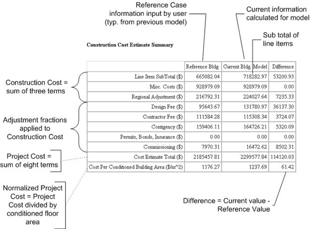
Figure 144. Economics Cost Modeling
“Line Item Subtotal” is the sum of items explicitly modeled in the cost estimate. For the reference building, this value is input by the user. For the current building, this value is the sum of line items which are detailed in Cost Line Item Details table that follows.
“Misc. Cost” is the product of the user-defined Miscellaneous Cost Model (per Square Meter) and the conditioned floor area.
“Regional Adjustment” is the produce of the user-defined Regional Adjustment Factor and the conditioned floor area.
“Design Fee” is the product of the user-defined Design and Engineering Fee Fraction and the subtotal for construction costs (which includes the Line Item Subtotal, Misc. Cost, and Regional Adjustment).
“Contractor Fee” is the product of the user-defined Contractor Fee Fraction and the subtotal for construction costs (which includes the Line Item Subtotal, Misc. Cost, and Regional Adjustment).
“Contingency” is the product of the user-defined Contingency Fraction and the subtotal for construction costs (which includes the Line Item Subtotal, Misc. Cost, and Regional Adjustment).
“Permits, Bonds, and Insurance” is the product of the Permits, Bonding, Insurance Fraction and the subtotal for construction costs (which includes the Line Item Subtotal, Misc. Cost, and Regional Adjustment).
“Commissioning” is the product of the user-defined Commissioning Fee Fraction and the subtotal for construction costs (which includes the Line Item Subtotal, Misc. Cost, and Regional Adjustment).
“Cost Estimate Total” is the sum of eight items above and represents the total project cost estimate.
“Cost per Conditioned Building Area” is the Cost Estimate Total divided by the total conditioned floor area. This represents a normalized cost intensity.
Life-cycle costing is used with building energy simulation in order to justify energy efficiency upgrades. Many alterative building technologies that result in energy savings cost more initially, or may cost more to maintain, than traditional solutions. In order to justify selecting these energy savings technologies, it is essential to combine both initial and future costs in the decision process. Using life-cycle costs provides a framework to combine initial costs and future costs into a single combined measure, called the “present value.” Present value is a metric that combines all costs and reduces (or discounts) those costs that occur in the future. Discounting future costs is based on the principal of the time value of money.
The calculations are based on discounting the future values according to normal life-cycle costing techniques as described in NIST Handbook 135 “Life-Cycle Costing Manual for the Federal Energy Management Program.”
The following is a list of life-cycle costing related objects that provide a way to describe the parameters and costs associated with the life-cycle of a building or building system:
n LifeCycleCost:Parameters
n LifeCycleCost:RecurringCosts
n LifeCycleCost:NonrecurringCost
n LifeCycleCost:UsePriceEscalation
n LifeCycleCost:UseAdjustment
The utility costs (see UtilityCost:Tariff) and first costs (see ComponentCost:LineItem) are calculated by EnergyPlus are used along with other current and future costs input using the LifeCycleCost:RecurringCosts and LifeCycleCost:NonrecurringCost objects and these are combined these into the present value life-cycle cost metric. The LifeCycleCost:Parameters object establishes the set of assumptions for the analysis along with LifeCycleCost:UsePriceEscalation (often from a DataSet) and LifeCycleCost:UseAdjustment.
It is important to understand that the comparison of different simulation results and their present values is not performed by EnergyPlus. Instead, EnergyPlus provides the present value calculations for a specific simulation combining the energy costs, first costs, and future costs and you need to make the comparison between the results of multiple simulations.
The results of using the LifeCycleCost objects are included automatically in the tabular report file whenever the LifeCycleCost:Parameters object is present. The report appearing in the tabular report file is titled “Life Cycle Cost Report.” This report shows the costs and the timing of costs, often called “cash flows,” along with the present value in several different tables. The tabular results would show the present value of all current and future costs.
The datasets file “LCCusePriceEscalationDataSet2010.idf” includes the energy escalation factors from the NIST Handbook 135 annual supplement as of 2010. These are necessary to use because the expected change in price for electricity and various fuels does not change at the same rate as inflation.
Life-cycle costing should not be confused with life-cycle analysis. With life-cycle costing the result is an economic evaluation of current and future expenditures in order to make a decision on alternative investments. In life cycle analysis, the environmental impact such as equivalent CO2 production involved in the materials, delivery, manufacturing, and construction are combined with environmental impacts of the building in operation and the eventual removal of the building and is used to understand the overall environmental impact or embodied energy.
Provides inputs related to the overall life-cycle analysis. It establishes many of the assumptions used in computing the present value. It is important that when comparing the results of multiple simulations that the fields in the LifeCycleCost:Parameters objects are the same for all the simulations. To aide in this comparison, the first table in the Life-Cycle Cost Report shows the inputs to this object. Only one LifeCycleCost:Parameters object is permitted for a file. When this object is present the tabular report file will contain the Life-Cycle Cost Report.
An identifying name used for the LifeCycleCost:Parameters object.
The field specifies if the discounting of future costs should be computed as occurring at the end of each year, the middle of each year, or the beginning of each year. The most common discounting convention uses the end of each year. Without a specific reason, the end of each year should be used. Some military projects may specifically require using the middle of each year. The year being used starts with the base year and month and repeats every full year. All costs assumed to occur during that duration are accumulated and shown as an expense either at the beginning, middle or end of the year. The options are:
n BeginningOfYear
n MidYear
n EndOfYear
This field is used to determine if the analysis should use constant dollars or current dollars which is related to how inflation is treated. The two options are:
n ConstantDollar
n CurrentDollar
The default option is ConstantDollars
If ConstantDollar is selected, then the Real Discount Rate input is used and it excludes the rate of inflation. If CurrentDollar is selected, then the Nominal Discount Rate input is used and it includes the rate of inflation. From NIST Handbook 135:
“The constant dollar approach has the advantage of avoiding the need to project future rates of inflation or deflation. The price of a good or service stated in constant dollars is not affected by the rate of general inflation. For example, if the price of a piece of equipment is $1,000 today and $1,050 at the end of a year in which prices in general have risen at an annual rate of 5 percent, the price stated in constant dollars is still $1,000; no inflation adjustment is necessary. In contrast, if cash flows are stated in current dollars, future amounts include general inflation, and an adjustment is necessary to convert the current-dollar estimate to its constant-dollar equivalent. This adjustment is important because constant- and current-dollar amounts must not be combined in an LCCA [life cycle cost analysis].”
For most analyses, using the ConstantDollar option will be easier since the effect of inflation may be ignored.
Enter the real discount rate as a decimal. For a 3% rate, enter the value 0.03. This input is used when the Inflation Approach is ConstantDollar. The real discount rate reflects the interest rates needed to make current and future expenditures have comparable equivalent values when general inflation is ignored. When Inflation Approach is set to CurrentDollar this input is ignored. If this field is blank and Inflation Approach is ConstantDollar, a warning is issued.
Enter the nominal discount rate as a decimal. For a 5% rate, enter the value 0.05. This input is used when the Inflation Approach is CurrentDollar. The real discount rate reflects the interest rates needed to make current and future expenditures have comparable equivalent values when general inflation is included. When Inflation Approach is set to ConstantDollar this input is ignored. If this field is blank and Inflation Approach is CurrentDollar, a warning is issued.
Enter the rate of inflation for general goods and services as a decimal. For a 2% rate, enter the value 0.02. If this field is not blank and Inflation Approach is ConstantDollar, a warning is issued.
Enter the month that is the beginning of study period, also known as the beginning of the base period. According to NIST 135 “the base date is the point in time to which all project-related costs are discounted in an LCCA [life cycle cost analysis]. The base date is usually the first day of the study period for the project, which in turn is usually the date that the LCCA is performed. In a constant dollar analysis, the base date usually defines the time reference for the constant dollars (e.g. 1995 constant dollars). It is essential that you use the same base data and constant-dollar year for all of the project alternatives to be compared. If you set the base date to the date that the LCCA is performed, then the constant dollar basis for the analysis will be the current date, and you can use actual costs as of that date without adjusting for general inflation.”
The choices are:
n January
n February
n March
n April
n May
n June
n July
n August
n September
n October
n November
n December
The default value is January.
This field could also be referred to as part of “the date of study.” It is used as the date for constant dollars.
Enter the four digit year that is the beginning of study period, such as 2010. The study period is also known as the base period. See more details in the previous field.
Enter the month that is the beginning of building occupancy. Energy costs computed by EnergyPlus are assumed to occur during the year following the service date. The service date must be the same or later than the Base Date. The choices are:
n January
n February
n March
n April
n May
n June
n July
n August
n September
n October
n November
n December
The default value is January. According to NIST Handbook 135:
“The service date is the date on which the project is expected to be implemented; operating and maintenance costs (including energy- and water-related costs) are generally incurred after this date, not before.”
This field could also be referred to as part of “beneficial occupancy date.”
Enter the four digit year that is the beginning of occupancy, such as 2010. See more details in the previous field.
Enter the number of years of the study period. It is the number of years that the study continues based on the start at the base date. The default value is 25 years. Only integers may be used indicating whole years. According to NIST Handbook 135, “the study period for an LCCA is the time over which the costs and benefits related to a capital investment decision are of interest to the decision maker. Thus, the study period begins with the base date and includes both the [planning/construction] period (if any) and the relevant service period for the project. The service period begins with the service date and extends to the end of the study period.”
Enter the overall marginal tax rate for the project costs. This does not include energy or water taxes. The single tax rate entered here is not intended to be a replacement of the complex calculations necessary to compute personal or corporate taxes; instead it is an approximate that may be used for a simple analysis assuming a constant tax rate is applied on all costs. The tax rate entered should be based on the marginal tax rate for the entity and not the average tax rate. Enter the tax rate results in present value calculations after taxes. Most analyses do not factor in the impact of taxes and assume that all options under consideration have roughly the same tax impact. Due to this, many times the tax rate can be left to default to zero and the present value results before taxes are used to make decisions. The value should be entered as a decimal value. For 15% enter 0.15. For an analysis that does not include tax impacts, enter 0.0. The default is 0.
For an analysis that includes income tax impacts, this entry describes how capital costs are depreciated. According to IRS Publication 946 – How to Depreciate Property "Depreciation is an annual income tax deduction that allows you to recover the cost or other basis of certain property over the time you use the property. It is an allowance for Fair market value the wear and tear, deterioration, or obsolescence of the Intangible property.” Details on which depreciation method to choose depends on the property being depreciated and IRS Publication 946 and your accountant are the best sources of information in determining which depreciation method to choose. Only one depreciation method may be used for an analysis and is applied to all capital expenditures. Only analyses that include tax impacts need to select a depreciation method.
The options are:
n ModifiedAcceleratedCostRecoverySystem-3year
n ModifiedAcceleratedCostRecoverySystem-5year
n ModifiedAcceleratedCostRecoverySystem-7year
n ModifiedAcceleratedCostRecoverySystem-10year
n ModifiedAcceleratedCostRecoverySystem-15year
n ModifiedAcceleratedCostRecoverySystem-20year
n StraightLine-27year
n StraightLine-31year
n StraightLine-39year
n StraightLine-40year
n None
Depreciation allowances reduce the actual/nominal tax dollars paid by the owner. Thus, analyses using depreciation should be conducted in nominal dollars. For an analysis that does not include tax effects, None should be selected.
The default value is None.
An example of this object in an IDF:
LifeCycleCost:Parameters,
TypicalLCC, !- Name
EndOfYear, !- Discounting Convention
ConstantDollar, !- Inflation Approach
0.034314, !- Real Discount Rate
, !- Nominal Discount Rate
, !- Inflation
January, !- Base Date Month
2010, !- Base Date Year
January, !- Service Date Month
2010, !- Service Date Year
25, !- Length of Study Period in Years
0.39, !- Tax rate
StraightLine-39year; !- Depreciation Method
Recurring costs are costs that repeat over time on a regular schedule during the study period. If costs associated with equipment do repeat but not on a regular schedule, use LifeCycleCost:NonrecurringCost objects instead.
The identifier used for the object. The name is used in identifying the cash flow equivalent in the output results in the Life-Cycle Cost Report.
Enter the category of the recurring costs. Choose the closest category. The options include:
n EnergyCosts
n WaterCosts
n Maintenance
n Repair
n Operation
n Replacement
n MinorOverhaul
n MajorOverhaul
n OtherOperational
The default value is Maintenance.
For recommendations on estimating other operational costs, see NIST 135 Section 4.6.3.
Enter the cost in dollars (or the appropriate monetary unit) for the recurring costs. Enter the cost for each time it occurs. For example, if the annual maintenance cost is $500, enter 500 here.
Enter when the costs start. The First Year of Cost is based on the number of years past the Start of Costs. For most maintenance costs, the Start of Costs should be Service Period. The options are:
n ServicePeriod
n BasePeriod
The default value is ServicePeriod.
This field and the Months From Start field together represent the time from either the start of the Service Period, on the service month and year, or start of the Base Period, on the base month and year (depending on the Start of Costs field) that the costs start to occur. Normally, for most maintenance costs that begin in the first year that the equipment is in service the Start of Costs is the Service Period and the Years from Start will be 0. Only integers should be entered representing whole years. The default value is 0.
This field and the Years From Start field together represent the time from either the start of the Service Period, on the service month and year, or start of the Base Period, on the base month and year (depending on the Start of Costs field) that the costs start to occur. Normally, for most maintenance costs the Start of Costs is the Service Period and the Months from Start will be 0. Only integers should be entered representing whole months. The Years From Start (times 12) and Months From Start are added together. The default value is 0.
This field and the Repeat Period Months field indicate how much time elapses between reoccurrences of the cost. For costs that occur every year, such as annual maintenance costs, the Repeat Period Years should be 1 and Repeat Period Months should be 0. Only integers should be entered representing whole years. The default value is 1.
This field and the Repeat Period Years field indicate how much time elapses between reoccurrences of the cost. For costs that occur every year the Repeat Period Years should be 1 and Repeat Period Months should be 0. For, costs that occur every eighteen months, the Repeat Period Years should be 1 and the Repeat Period Months should be 6. Only integers should be entered representing whole years. The Repeat Period Years (times 12) and Repeat Period Months are added together. The default value is 0.
Enter the annual escalation rate as a decimal. For a 1% rate, enter the value 0.01. This input is used when the Inflation Approach is CurrentDollar. When Inflation Approach is set to ConstantDollar this input is ignored. The default value is 0.
An example of this object in an IDF:
LifeCycleCost:RecurringCosts,
AnnualMaint, !- Name
Maintenance, !- Category
2000, !- Cost
ServicePeriod, !- Start of Costs
0, !- Years from Start
0, !- Months from Start
1, !- Repeat Period Years
0, !- Repeat Period Months
0; !- Annual escalation rate
A non-recurring cost happens only once during the study period. For costs that occur more than once during the study period on a regular schedule, use the LifeCycleCost:RecurringCost object.
The identifier used for the object. The name is used in identifying the cash flow equivalent in the output results in the Life-Cycle Cost Report.
Enter the category of the non-recurring costs. Choose the closest category. The options include:
n Construction
n Salvage
n OtherCapital
The default is Construction.
For recommendations on estimating capital and salvage (residual) costs, see NIST 135 Section 4.5.
Enter the non-recurring cost value. For construction and other capital costs the value entered is typically a positive value. For salvage costs, the value entered is typically a negative value which represents the money paid to the investor for the equipment at the end of the study period.
Enter when the costs start. The First Year of Cost is based on the number of years past the Start of Costs. For most non-recurring costs the Start of Costs should be Base Period which begins at the base month and year. The options are:
n ServicePeriod
n BasePeriod
The default value is BasePeriod
This field and the Months From Start field together represent the time from either the start of the Service Period, on the service month and year, or start of the Base Period, on the base month and year (depending on the Start of Cost field) that the costs start to occur. Normally, for most capital costs the Start of Costs is the Base Period and the Years from Start will be 0. These would be first costs for the building equipment or system. Salvage costs are usually shown as happening in the last year of the analysis. Only integers should be entered representing whole years. The default value is 0.
This field and the Years From Start field together represent the time from either the start of the Service Period, on the service month and year, or start of the Base Period, on the base month and year (depending on the Start of Cost field) that the costs start to occur. Normally, for most capital costs the Start of Costs is the Base Period and the Months from Start will be 0. Only integers should be entered representing whole months. The Years From Start (times 12) and Months From Start are added together. The default value is 0.
An example of this object in an IDF:
LifeCycleCost:NonrecurringCost,
EstimatedSalvage, !- Name
Salvage, !- Category
-2000, !- Cost
ServicePeriod, !- Start of Costs
20, !- Years from Start
0; !- Months from Start
The LifeCycleCost:UsePriceEscalation object will commonly be part of a dataset on life cycle costs. The values for this object may be found in the annual supplement to NIST Handbook 135 in Tables Ca-1 to Ca-5. A dataset file comes with EnergyPlus in the DataSet directory and includes the LCCusePriceEscalationDataSet2010.idf file which includes the value for the 2010 supplement to NIST 135. The object provides inputs for the escalations of energy and water costs assuming that they change differently than inflation. According to the NIST 135 supplement the values are “present projected fuel price indices for the four Census regions and for the United States. These indices, when multiplied by annual energy costs computed at base-date prices (i.e., as of April 1, 2010), provide estimates of future-year costs (also as of April 1) in constant base-date dollars. Constant-dollar cost estimates are needed when discounting is performed with a real discount rate (i.e., a rate that does not include general price inflation).”
The identifier used for the object. The name usually identifies the location (such as the state, region, country or census area) that the escalations apply to. In addition the name should identify the building class such as residential, commercial, or industrial and the use type such as electricity, natural gas, or water.
Enter the resource such as:
n Electricity
n FuelOil#1
n NaturalGas
n PropaneGas
n FuelOil#2
n Coal
n Steam
n Gasoline
n Diesel
n Water
This field and the Escalation Start Month define the time that corresponds to “Year 1 Escalation” such as 2010, when the escalation rates are applied. This field and the Escalation Start Month define the time that escalation begins.
Escalation Start Month
This field and the Escalation Start Year define the time that corresponds to “Year 1 Escalation” such as 2010, when the escalation rates are applied. This field and the Escalation Start Year define the time that escalation begins.
The choices are:
n January
n February
n March
n April
n May
n June
n July
n August
n September
n October
n November
n December
The default value is January. According to NIST Handbook 135:
The escalation in price of the energy or water use for the first year expressed as a decimal.
The escalation in price of the energy or water use for the n-th year expressed as a decimal. This object is extensible and often includes 25 to 50 years of projected values.
If the number of years in LifeCycleCost:UsePriceEscalation is less than the number of years in the analysis period, the remaining years will assume no escalation. Normal inflation will be the only affect for these years.
An example of this object in an IDF:
LifeCycleCost:UsePriceEscalation,
NorthEast Residential-Electricity, !- Name
Electricity, !- Resource
2010, !- Escalation Start Year
January, !- Escalation Start Month
0.9374, !- Year 1 Escalation
0.9790, !- Year 2 Escalation
1.0138, !- Year 3 Escalation
1.0127, !- Year 4 Escalation
1.0096, !- Year 5 Escalation
1.0177, !- Year 6 Escalation
1.0279, !- Year 7 Escalation
1.0334, !- Year 8 Escalation
1.0327, !- Year 9 Escalation
1.0382, !- Year 10 Escalation
1.0454, !- Year 11 Escalation
1.0494, !- Year 12 Escalation
1.0564, !- Year 13 Escalation
1.0587, !- Year 14 Escalation
1.0549, !- Year 15 Escalation
1.0566, !- Year 16 Escalation
1.0630, !- Year 17 Escalation
1.0707, !- Year 18 Escalation
1.0857, !- Year 19 Escalation
1.0953, !- Year 20 Escalation
1.1063, !- Year 21 Escalation
1.1165, !- Year 22 Escalation
1.1227, !- Year 23 Escalation
1.1292, !- Year 24 Escalation
1.1349, !- Year 25 Escalation
1.1414, !- Year 26 Escalation
1.1480, !- Year 27 Escalation
1.1550, !- Year 28 Escalation
1.1617, !- Year 29 Escalation
1.1686; !- Year 30 Escalation
Used by advanced users to adjust the energy or water use costs for future years. This should not be used for compensating for inflation but should only be used to increase the costs of energy or water based on assumed changes to the actual use of water or energy, such as due to changes in the future function of the building or the impact of future adjacent buildings on energy use. This object is not commonly used and should be used with caution. The adjustments begin at the start of the service period.
The identifier used for the object.
Enter the resource such as:
n Electricity
n NaturalGas
n Steam
n Gasoline
n Diesel
n Coal
n FuelOil #1
n FuelOil #2
n Propane
n Water
The multiplier to be applied to the end use cost for the first year in the service period. The total utility costs for the selected end use is multiplied by this value. For no change enter 1.0.
The multiplier to be applied to the end use cost for each following year. The total utility costs for the selected end use is multiplied by this value. For no change enter 1.0. This object is extensible and often includes 25 to 50 years of values.
An example of this object in an IDF:
LifeCycleCost:UseAdjustment,
ElecAdjustment, !- Name
Electricity, !- Resource
1.0000, !- Year 1 Multiplier
1.0022, !- Year 2 Multiplier
1.0023, !- Year 3 Multiplier
1.0024, !- Year 4 Multiplier
1.0025, !- Year 5 Multiplier
1.0026, !- Year 6 Multiplier
1.0027; !- Year 7 Multiplier
By default, the predefined reports related to economics use the $ symbol. If a different symbol should be shown in the predefined reports to represent the local currency this object can be used. If the object is not used, the $ sign is used in the reports. Only one CurrencyType object is allowed in the input file.
The commonly used three letter currency code for the units of money for the country or region. Based on ISO 4217 currency codes. Common currency codes are USD for the U.S. Dollar represented with ‘$’ and EUR for Euros represented with ‘€’. The three letter currency codes can be seen at the following web sites (as of 2008):
When a three letter currency code is specified, the HTML file will use either an ASCII character if available or one or more UNICODE characters. Since not all browsers and all fonts used by browsers completely support UNICODE, not all currency symbols may be rendered correctly. If a box or a box with four small letters appears, this indicates that the browser and its fonts do not support a specific UNICODE character.
For text reports, an ASCII representation of the currency code will be used. Since ASCII is much more limited than UNICODE, many times the three letter currency code will be shown in the reports.
Since forms of currency change, please contact EnergyPlus support if a new currency code and symbol are needed.
In order to assess a group of alternatives, the Parametric objects can be used in a single file as an alternative of maintaining a group of files with small differences. Updating portions of the multiple files that do not change between permutations becomes tedious and error prone and may lead to incorrect conclusions concerning the energy savings of specific measures. The ParametricPreprocessor.exe program (described in the AuxiliaryPrograms document) interprets the following objects in a single file and creates the group of files automatically. The objects in the group are:
· Parametric:SetValueForRun
· Parametric:Logic
· Parametric:RunControl
· Parametric:FileNameSuffix
A simple example of part of an IDF file is shown below:
Parametric:SetValueForRun,
$insDepth, !- Parameter Name
0.0508, !- Value 1
0.0762, !- Value 2
0.1016, !- Value 3
0.1270; !- Value 4
Material,
IN1, !- Name
VeryRough, !- Roughness
=$insDepth, !- Thickness {m}
2.3000000E-02, !- Conductivity {W/m-K}
24.00000, !- Density {kg/m3}
1590.000, !- Specific Heat {J/kg-K}
0.9000000, !- Thermal Absorptance
0.5000000, !- Solar Absorptance
0.5000000; !- Visible Absorptance
In this example, the parameter $insDepth is used in the Material object to describe the thickness of the material, in this case insulation. For the first simulation, $insDepth is set to 0.0508 (2 inches) shown as the first value in the Parametric:SetValueForRun object. This value is then substituted in where ever the $insDepth is shown in the file, in this example, in the Material object. The simulation would use this first value and produce a set of results based on this insulation thickness. The second simulation would use the second value of the Parametric:SetValueForRun object of 0.0762 (3 inches) for the thickness of the insulation described in the Material object. This would then be simulated with a second set of results. This would be repeated a third time with 0.1015 (4 inches) and 0.1270 (5 inches) of insulation.
A new IDF file is created for each of these simulations and is named the original name of the file plus either a number or a user defined suffix (if Parametric:FileNameSuffix is used). Looking at how these created IDF files show the substituted values can help understand problems that may occur.
The “=$insDepth” is a simple substation but could also be a more complex expression involving operators and predefined functions such as
=$insDepth * 1.1 + 0.0004 * SQRT(12)
Many sets of simulations can be defined just using different Parametric:SetValueForRun objects but for more advanced sets of parametric runs, the Parametric:Logic object can be used to perform additional calculations, logical operations, and to exclude entire objects in the file. The Parametric:RunControl allows individual runs to be performed or not. The Parametric:FileNameSuffix object controls the naming of the resulting sets of output files.
Expressions can occur anywhere in the IDF file as a field value if the expression begins with an equals sign (=) and can also occur in assignment statements in the Parametric:Logic object. The operators include: +, -, *, /, ^ (exponent), && (and), || (or), ==, >, <, <=, >=, <>, and //. These are computed using standard operator precedence rules. The parenthesis are used to execute sub-expressions with higher precedence. Some built in functions, such as ABS, ACOS, ASIN, ATAN, COS, EXP, INT, LEN, LOG, MOD, NOT, SIN, SQRT, TAN are supported in expressions. Theses built in functions all take a single argument.
The order that the parameters are processed is important to understand their values. Like other objects in EnergyPlus, the order that they occur in the file is not important. The order of evaluation is:
1) Parameter values are based on Parametric:SetValueForRun
2) All lines of the Parametric:Logic object are evaluated
3) All embedded expressions in the file are evaluated
The core parametric object is Parametric:SetValueForRun which sets the parameters value to different values depending on which run is being simulated.
For example
Parametric:SetValueForRun
$ConstructionToUse, !- Parameter Name
TiltUpConcreteWall, !- Value for run 1
BlockWall, !- Value for run 2
SteelFrameWall, !- Value for run 3
WoodFrameWall; !- Value for run 4
Parametric:SetValueForRun
$WallRValue, !- Parameter Name
5, !- Value for run 1
8, !- Value for run 2
11, !- Value for run 3
17; !- Value for run 4
Using Parametric:SetValueForRun, the value is set based on the which run number is currently being simulated. Multiple objects can be used and a set of parameter values would be defined for a given simulation. For example, the 3rd simulation would assign the "Value 3" value, 11, to the parameter $WallRValue and the “Value 3” value, “SteelFrameWall” to $ConstructionToUse. Since many Parametric:SetValueForRun objects can be used at once, all of the 3rd values would be assigned to the appropriate parameters. In IDF Editor, this object will appear as a table of values with each row being all the parameter values for a specific simulation and each column belonging to a specific parameter.
The name of the parameter. It must begin with the dollar sign character, and the second character must be a letter. The parameter name, unlike a typical EnergyPlus name, cannot contain spaces or any characters other than letters and numerals.
The value that should be substituted for the parameter on the n-th simulation. If multiple Parametric:SetValueForRun objects exist and they have different number of fields, the last field value will be used for the remaining field values. This means that to set all values the same, only the first value needed to be entered.
The approach of using parameters and expressions, by itself, is very flexible and allows for many possible parametric simulations but it does not allow for objects to be included for some parametric cases and not others. For example, you might want an overhang on a window in some parametric runs and not others. The Parametric:Logic object can help in that scenario.
A single Parametric:Logic object is allowed per file. It has a freeform syntax including IF and SELECT blocks with each field in the object representing a single "line" of code. Essentially, this logic object looks like simple programming code.
Parametric:Logic,
Main, !- name
IF $insDepth < 0.1, !- parametric logic line 1
DISABLE “MaterialWallBoard”, !- parametric logic line 2
DISABLE “MaterialExtFinish”, !- parametric logic line 3
ENDIF; !- parametric logic line 4
In addition, lines could contain assignment statements in the form of
parameter = expression such as the second control line in the following example.
Parametric:Logic,
Main, !- name
PARAMETER $THICKNESS, !- parametric logic line 1
$THICKNESS = 0.01 * $CMDEPTH, !- parametric logic line 2
IF $THICKNESS > 0.5, !- parametric logic line 3
DISABLE “MaterialWallBoard”, !- parametric logic line 4
DISABLE “MaterialExtFinish”, !- parametric logic line 5
ENDIF; !- parametric logic line 6
The statements include PARAMETER, IF, ELSE, ELSEIF, ENDIF, SELECT, CASE, DEFAULT, ENDSELECT, ENABLE, DISABLE, and REMARK. Nested IF and SELECT statements are allowed. All objects are enabled until they are specifically disabled using the DISABLE statement and could be later re-enabled with ENABLE. An object that is named with the DISABLE statement would not appear in that simulation run.
The PARAMETER statement declares the name of the parameter. It is necessary that every parameter used in the Parametric:Logic object be initialized using the PARAMETER statement unless the parametes are created using the Parametric:SetValueForRun object. Requiring explicit parameter declaration reduces errors in software programming. Parameter names would not be case sensitive.
The DISABLE and ENABLE commands can have one or two arguments. If a second argument is present it is the kind of object.
DISABLE “MaterialWallBoard” “Material”, !- parametric control line 4
The following sections describe each type of statement in more detail.
As previously shown, the simplest IF block is in the form of
IF <conditional-expression>
<true-block-of-statements>
ENDIF
The <conditional-expression> usually contains a logical comparison operator such as:
== equal
> greater than
< less than
<= less than or equal to
>= greater than or equal to
<> not equal to
The <true-block-of-statements> can contain other statements including other lines of IF and ENDIF. These statement are only executed when the <conditional-expression> evaluates to true. If the <conditional-expression> is false, none of the statements before the ENDIF are executed and instead execution begins again with the statement after the ENDIF statement.
Another form of the IF block can contain the ELSE statement:
IF <conditional-expression>
<true-block-of-statements>
ELSE
<false-block-of-statements>
ENDIF
Like the simpler IF ENDIF form the <conditional-expression> is computed and the <true-block-of-statements> are executed if it is true. The additional feature of this form is that if the <conditional-expression> is false, the <false-block-of-statements> is executed instead of the <true-block-of-statements>.
The most complex form of the IF block contains both ELSEIF statement (or statements) and the ELSE statement:
IF <conditional-expression-1>
<true-block-of-statements-1>
ELSEIF <conditional-expression-2>
<true-block-of-statements-2>
ELSEIF <conditional-expression-2>
<true-block-of-statements-2>
ELSE
<false-block-of-statements>
ENDIF
This form allows more complex logic to be expressed. If the <conditional-expression-1> is true then <true-block-of-statements-1> executed and when that is complete, execution resumes after the ENDIF statement. If <conditional-expression-1> is false then the ELSEIF <conditional-expression-2> is evaluated and if that is true then <true-block-of-statement-2> is executed. On the other hand, if <conditional-expression-2> is false, then the next ELSEIF conditional expression is evaluated following the same patter if another ELSEIF is present, otherwise, the <false-block-of-statements> after the ELSE are executed. Another way of thinking of this block is that the conditional expressions are evaluated from the top to the bottom until one is found to be true and then the associated block of statements are executed. If none of the conditional expressions is true, the <false-block-of-statements> are executed.
The SELECT block is related to the IF block but is for the specific case of trying to match a variable with several specific values. The form of the SELECT block is:
SELECT <expression>
CASE <constant-1>
<case-block-of-statements-1>
CASE <constant-2>
<case-block-of-statements-2>
CASE <constant-3>
<case-block-of-statements-3>
DEFAULT
<default-block-of-statements>
ENDSELECT
With any number of CASE statements. The <expression> is evaluated and compared to the constants with each CASE statement. If a match is found the corresponding <case-block-of-statements> are executed otherwise if no match if found the <default-block-of-statements> is excecuted. One one matching CASE statement for each SELECT block is executed. An example of how this works is shown below:
Parametric:SetValueForRun,
$EndMonth,
2;
Parametric:Logic,
Main2,
PARAMETER $EndDay,
SELECT $EndMonth,
CASE 1,
$EndDay = 31,
CASE 2,
$EndDay = 28,
CASE 3,
$EndDay = 31,
CASE 4,
$EndDay = 30,
CASE 5,
$EndDay = 31,
CASE 6,
$EndDay = 30,
CASE 7,
$EndDay = 31,
CASE 8,
$EndDay = 31,
CASE 9,
$EndDay = 30,
CASE 10,
$EndDay = 31,
CASE 11,
$EndDay = 30,
CASE 12,
$EndDay = 31,
DEFAULT,
$EndDay = 30,
ENDSELECT;
With this example the $EndDay value would be set to 28.
The ENABLE and DISABLE statements specifically are for removing (and not removing) other objects that appear in the EnergyPlus IDF file. It has two syntaxes:
DISABLE <objectname>
and
DISABLE <objectname>, <kind-of-object>
The DISABLE statement removes the object identified with either <objectname> or the combination of <objectname> and <kind-of-object> if the <objectname> is not unique in the EnergyPlus input file. By default, all objects are enabled in the input file. Objects need to be specifically disabled using the DISABLE statement. After an object is disabled in can later be re-enabled with the ENABLE statement which has similar syntax.
DISABLE <objectname>
and
DISABLE <objectname>, <kind-of-object>
Parametric:Logic,
Main,
DISABLE "SOUTH WALL OVERHANG";
Shading:Zone:Detailed,
SOUTH WALL OVERHANG, !- Name
ZONE SURFACE SOUTH, !- Base Surface Name
SCH 2, !- Transmittance Schedule Name
4, !- Number of Vertices
0.0,-1.0,3.0, !- X,Y,Z ==> Vertex 1 {m}
0.0,0.0,3.0, !- X,Y,Z ==> Vertex 2 {m}
4.0,0.0,3.0, !- X,Y,Z ==> Vertex 3 {m}
4.0,-1.0,3.0; !- X,Y,Z ==> Vertex 4 {m}
An object that is named with the DISABLE statement would not appear in that simulation run.
The REMARK statement is simply a way to include a comment in the Parametric:Logic fields. The text that follows the REMARK statement is ignored.
The definition of the Parametric:Logic object is shown below:
The name of the Parametric:Logic object.
The line that contains one statement in one of the following forms:
<parameter> = <expression>
PARAMETER <parameter>
IF <expression>
ELSEIF <expression>
ELSE
ENDIF
SELECT <expression>
CASE <constant>
DEFAULT
ENDSELECT
ENABLE <constant>
ENABLE <constant> <constant>
DISABLE <constant>
DISABLE <constant> <constant>
REMARK <text to ignore>
The following Parametric:RunControl object controls which runs are simulated. The series of entries indicate if the run should be performed or not. This object is optional and if it is not included all runs are performed.
The name of the optional Parametric:RunControl object.
The value of the field can be either a yes or no. It cannot contain a parameter.
The file name of the IDF files that are created for each run and the output files for each run are based on the name of the file plus a “suffix”. The suffixes can be defined using the Parametric:FileNameSuffix object or if the object is missing will default to the run number.
The name of the optional Parametric:FileNameSuffix object.
The value of the field is added to the IDF file name to create the resulting IDF file and output files. It cannot contain a parameter.
Several items are used to specify what will appear in the output file(s). The output is described in the next section of this document.
One of the most important outputs for EnergyPlus is the Variable Dictionary reports – these contain the key variable names for each simulation. This single input object is used to produce two important reports that are used to identify the specific report variables and meters available for a specific EnergyPlus model. Two output files are produced (eplusout.rdd & eplusout.mdd) that list the names of the report variables and meters for that simulation. You may need to run your simulation once and produce these files before you ask for specific output variables (rdd) or meters (mdd) (see Output:Variable and Output:Meter). Variables available, to some extent, depend on the simulation input. Variables are “set up” during the initial “get input” processing done within the modules. Therefore, an item that is specific to a certain type of coil would not be available if that coil were not used during the simulation. This command will produce a list of variables available for reporting.
For this field there are two choices: IDF and regular. The regular option is the default and produces a listing that shows the type of variable: Zone or HVAC, Average or Sum. “Zone” variables are calculated and can be reported after each Zone/Heat Balance timestep (ref: Timesteps input object). “HVAC” variables are calculated and can be reported with each variable HVAC timestep. “Average” variables will be averaged over the time interval being reported whereas “Sum” variables are summed over that time interval. (Meter variables are always summed.) Units for the variable are shown in “[}”.
For this field there are two choices: Name and Unsorted. By default, the listing of available reporting variables are unsorted – listed in the streaming order that EnergyPlus generates them. Or, you can have them sorted by name.
Examples of the options for this object follow:
Output:VariableDictionary,regular;
Results of this are shown in the Output Details document under the eplusout.rdd (output variables) and eplusout.mdd (meter variables) files.
The eplusout.mdd file has a similar format for meters:
The common workflow process of examining Variable Dictionary Reports and then adding reporting requests to an IDF file can be facilitated by using the following alternate form (Report Name = IDF) of the input object that requests the reports.
Output:VariableDictionary, IDF;
A sorted request would appear similarly:
Output:VariableDictionary, IDF, Name;
There are two specific objects for surfaces: Output:Surfaces:List and Output:Surfaces:Drawing – as the names imply, the list reports are simple text reports that are contained in one of the output files whereas the drawing reports will create files that are used in other graphic tools.
These objects and their use is described in the following:
Examples of using the Output:Surfaces:List object follow:
An example input object for this report follows.
Output:Surfaces:List, Lines;
The above IDF line will produce a simple file of line segments that constitute the surfaces in the IDF file. This file is the “lines” report (eplusout.sln) and is decribed in more detail in the Output Details and Examples document.
An extra option of entering “IDF” in this field directs the Lines report to produce coordinates transformed into Surface Geometry (Lower Left Corner, CounterClockwise, WorldCoordinates). An example of this follows.
Output:Surfaces:List, Lines, IDF;
The result is put on the eplusout.sln file and is nearly ready for putting into a IDF. Again, it is described in more detail in the Output Details and Examples document.
An example input object for this report follows.
Output:Surfaces:List, Details;
This report (in eplusout.eio) contains details about each surface – including surface name, associated zone, area, approximate height and width, tilt, outward facing angle. Specific details on this report can be found in the Output Details and Examples document.
An example input object for this report follows.
Output:Surfaces:List, Vertices;
This report (in eplusout.eio) contains the vertices of each surface along with surface name and other information. Specific details on this report can be found in the Output Details and Examples document.
An example input object for this report follows.
Output:Surfaces:List, DetailsWithVertices;
This report (in eplusout.eio) is the combination of the two preceding reports (Details and Vertices). Specific details on this report can be found in the Output Details and Examples document.
An example input object for this report follows.
Output:Surfaces:List, ViewFactorInfo;
This report (in eplusout.eio) provides details about the thermal radiation exchange view factors and interchange factors. Specific details on this report can be found in the Output Details and Examples document.
Examples of using the Output:Surfaces:Drawing object follow:
Examples input objects follow.
Output:Surfaces:Drawing, DXF;
Output:Surfaces:Drawing, DXF, RegularPolyline;
Output:Surfaces:Drawing, DXF, Triangulate3DFace, mycolorscheme;
The above IDF specification will produce a DXF file (eplusout.dxf) of the surfaces in the IDF file. Only one DXF report can be produced. More specifics on this report can be found in the Output Details and Examples document.
As indicated in the example, you can select among three different ways that surfaces with more than four sides will appear in the DXF file. These are:
n ThickPolyline – surface with >4 sides will be represented as a “thick” line in the appropriate surface color. It will look like a hole in the drawing with a thicker edge.
n RegularPolyline – surface with >4 sides will be represented as a regular line in the appropriate surface color. It will look like a hole in the drawing.
n Triangulate3DFace– surface with >4 sides will be “triangulated” internally within EnergyPlus. This is only for drawing purposes and does not affect the calculations in any way. In a line version of the DXF, it will appear that the surface is split into triangles. In a solid view, the surface will appear similar to surfaces with <=4 sides. The triangulation algorithm is not perfect and warnings do result when the software cannot triangulate the surface.
This field can be used to control the color scheme in the DXF file by entering the name of an OutputControl:SurfaceColorScheme object. Using OutputControl:SurfaceColorScheme, you can define color schemes for surface representation. This feature will let you align the colors with the software of your choice (colors don’t seem to be standard across DXF viewers).
Several software programs can render this file into something viewable and are described in more detail in the Output Details and Examples document under the file name (eplusout.dxf).
An example input object for this report follows.
Output:Surfaces:Drawing, DXF:WireFrame;
The above IDF specification will produce a DXF (Drawing Exchange Format) file (eplusout.dxf) of the surfaces in the IDF file using the DXF “Lines” command – producing only a wire frame capable file. More specifics on this report can be found in the Output Details and Examples document. Only one DXF report can be produced.
Examples input objects for this report follow.
Output:Surfaces:Drawing, VRML;
Output:Surfaces:Drawing, VRML, Triangulate3DFace;
The above IDF specification produces a VRML (Virtual Reality Modeling Language) file (eplusout.wrl) of the surfaces in the IDF file. Only one VRML report can be produced. VRML files can be viewed in many web browsers after adding a “plug-in” and there are some stand-alone viewers as well. More specifics on this report can be found in the Output Details and Examples document.
As indicated in the example, you can select several figure types (for >4 sided surfaces) in the DXF report. These are:
n ThickPolyline – surface with >4 sides will be represented as a “thick” line in the appropriate surface color. It will look like a hole in the drawing with a thicker edge.
n RegularPolyline – surface with >4 sides will be represented as a regular line in the appropriate surface color. It will look like a hole in the drawing.
n Triangulate3DFace – surface with >4 sides will be “triangulated” internally within EnergyPlus. This is only for drawing purposes and does not affect the calculations in any way. In a line version of the VRML, it will appear that the surface is split into triangles. In a solid view, the surface will appear similar to surfaces with <=4 sides. The triangulation algorithm is not perfect and warnings do result when the software cannot triangulate the surface.
Color schemes are not applicable for VRML reports.
This is a condensed reporting that illustrates the full range of schedule values – in the style of input: DaySchedule, WeekSchedule, and Annual Schedule.
This field should contain the word Hourly or TimeStep to obtain the respective reports.
Output:Schedules, Hourly; ! values on hourly increments (day schedule resolution)
Output:Schedules, TimeStep; ! will give them at the timestep of the simulation
This report is placed on the eplusout.eio file. Details of this reporting are shown in the Output Details and Examples document. Schedule values over time can also be obtained in the EnergyPlus Standard Output (in eplusout.eso) using Output:Variable objects.
This report content is added to the “eplusout.eio” file. It shows the calculated results related to conduction transfer functions for each construction. It also includes similar details about the windows. Specific details on this report can be found in the Output Details and Examples document. The following input object is used to obtain the Construction report.
Output:Constructions,Constructions;
Either field can contain the word “Constructions” to get the constructions report.
Or either field can contain the word “Materials” to obtain the Materials report.
This report content is added to the “eplusout.eio” file. It provides a summary of the thermal properties and thickness of the construction and window materials in the model. Specific details on this report can be found in the Output Details and Examples document. The following input object is used to obtain the Materials report.
Output:Constructions,Materials;
Daylight factors are ratios of interior illuminance at a specific location to exterior horizontal illuminance. In EnergyPlus, they are pre-calculated hourly for every shadow calculation day for every exterior window of a daylight zone. The pre-calculated daylight factors are interpolated between hours and for the actual sky conditions in the time-step calculation of the daylighting performance of daylight zones.
EnergyPlus reports the daylight factors for four sky types (clear, turbid clear, intermediate, and overcast) at noon time (12:00pm) for each exterior windows (base window without shading) in the eio file when the daylight factors are first calculated. This new object can report all hourly pre-calculated daylight factors. Details of the report are shown in the Output Details document.
This field is used to select days to report the daylight factors. Two choices are “SizingDays” and “AllShadowCalculationDays”. The SizingDays choice will output the daylight factors for only the sizing calculation days, while the AllShadowCalculationDays choice will output daylight factors for all shadow calculation days.
This report content is added to the “eplusout.edd” file. It shows information useful for the Energy Management System. The user can select the level of detail reported to the file using the fields in this object. However, there must be some other EMS-related input objects in the input file before this report will be generated.
This field is used to control the level of output reporting related to the EMS actuators that are available for a particular model. When EnergyPlus runs with EMS, it sets up a wide array of possible actuators that the EMS could use. (To actually use them requires an EnergyManagementSystem:Actuator object). Actuator availability dictionary reporting is provided to show the user what actuators are available in a particular building model. Regardless of the level of reporting chosen here, the same set of actuators are actually available. There are three levels to choose from. The “None” choice means that no reporting of available actuators is done. The “NotByUniqueNames” level means that the output includes only the types of actuators and their control options but not the unique, user-defined names that identify a specific actuator in the model. The “Verbose” level means that the output includes all combinations of actuator types, control types, and the unique names of specific actuators. The verbose level provides all the information needed for input in an EnergyManagementSystem:Actuator input object.
This field is used to control the level of output reporting related to the EMS internal variables that are available for a particular model. When EnergyPlus runs with EMS, it sets up a wide array of possible internal data sources that the EMS could use. (To actually use them requires an EnergyManagementSystem:InternalVariable object). Internal variable availability dictionary reporting is provided to show the user what internal data are available. Regardless of the level of reporting chosen here, the same internal data are available. There are three levels to choose from. The “None” choice means that no reporting of available internal data is done. The “NotByUniqueNames” level means that the output includes only the types of internal data but not the unique names that identify a specific instances in the model. The “Verbose” level means that the output includes all combinations of internal variables and the unique names of specific instances. The verbose level provides all the information needed for an EnergyManagementSystem:InternalVariable input object.
This field is used to control the level of output reporting related to the execution of EnergyPlus Runtime Language, or Erl. This reporting is valuable for debugging Erl programs. When Erl programs are run inside EnergyPlus they can report error situations (such as divide by zero) or a full trace of each Erl statement. There are three levels of reporting. The “None” choice means that no reporting of Erl debug information is done. The “ErrorsOnly” choice means that Erl debugging traces are only output if the statement produces an error situation. The “Verbose” choice means that Erl debugging traces are done for each line of each Erl program. The verbose setting needs to be used with care because a large model with a long runperiod can easily create an EDD file that is too large for most computer systems (e.g. many GBs of text).
An example of this object follows.
Output:EnergyManagementSystem,
Verbose, ! Actuator Availability Dictionary Reporting
Verbose, ! Internal Variable Availability Dictionary Reporting
ErrorsOnly; ! EnergyPlus Runtime Language Debug Output Level
This object provides control over the colors that appear in the DXF report, by surface. In addition, the Datasets folder contains example objects, including the “original” color scheme (prior to the 2.1 release).
This assigns a unique name to this colorscheme data set. This name is used in the DXF output objects.
This set of fields can range from none (accepting the default colors) up to 15 sets with individual types of building elements assigned a color number. (drawing element types not assigned a color number will use the default color numbers)
This field uses a choice of the drawing types (Text, Walls, Windows, GlassDoors, Doors, Roofs, Floors, DetachedBuildingShades, DetachedFixedShades, AttachedBuildingShades, Photovoltaics, TubularDaylightDomes, TubularDaylightDiffusers, DaylightReferencePoint1, DaylightReferencePoint2) for the color number assignment in the following field.
This is a color “number” from 0 to 255. DXF display software is not standardized – you may need to play around with these numbers if you don’t like the supplied default color scheme.
This input object is created to allow more user control over some aspects of output reporting. Specifically, the reporting of “Time setpoint not met” hours See thermostat reporting (ZoneControl:Thermostat Outputs).
This field allows the entry of a value for the tolerance away from the heating setpoint reporting. If the zone temperature is below the heating setpoint by more than this value, the following report variables will increment as appropriate
Time Heating Setpoint Not Met
Time Heating Setpoint Not Met While Occupied
This also impacts table report "Annual Building Utility Performance Summary" subtable "Comfort and Setpoint Not Met Summary".
This field allows the entry of a value for the tolerance away from the cooling setpoint reporting. If the zone temperature is above the cooling setpoint by more than this value, the following report variables will increment as appropriate
Time Cooling Setpoint Not Met
Time Cooling Setpoint Not Met While Occupied
This also impacts table report "Annual Building Utility Performance Summary" subtable "Comfort and Setpoint Not Met Summary".
As seen in an IDF:
OutputControl:ReportingTolerances,.21,.21;
This input object is used request results reporting. As shown above in the Variable Dictionary Report section, there are many different output variables available for reporting results from EnergyPlus. The Output:Variable object is primarily used for reporting time series data at various frequencys.
Each Output:Variable object causes a specific number assignment for outputs. For example, you could request separate reporting for the outside temperature:
Output:Variable,*,outdoor dry bulb,timestep;
Output:Variable,*,outdoor dry bulb,hourly;
Output:Variable,*,outdoor dry bulb,monthly;
This alpha field can be used to make a specific reference for reporting. In addition to the generic variable names listed in the Variable Dictionary Report for the input file, variables will also have a key designator (such as Zone name or Surface name). You can reference the standard output file (eplusout.eso) to see just how these look.
41,2,ZN001:WALL004,Surface Inside Temperature[C]
42,2,ZN001:WALL004,Surface Outside Temperature[C]
43,2,ZN001:WALL004,Surface Int Convection Coeff[W/m2-K]
44,2,ZN001:WALL004,Surface Ext Convection Coeff[W/m2-K]
46,2,ZONE ONE,Zone Mean Radiant Temperature[C]
47,2,ZONE ONE,Zone Total Internal Latent Gain [J]
51,2,ZONE ONE,Zone Lights Electric Consumption[J]
58,2,ZONE ONE,Zone/Sys Air Temperature[C]
For example, in the previous block, the key for the surface variables is ZN001:WALL004 whereas the key for the zone variables is ZONE ONE (note that the space is required and significant for this key).
You can have all keys listed in the standard output file by putting a “*” in this field or you can have specific items listed by putting in a key value. If this field is left blank, it will use a * as the default (i.e., you will get all variables of Variable Name).
This alpha field is the variable name (you don’t have to put on the units) that is shown in the Variable Dictionary Report file (eplusout.rdd). This field is required.
This field specifies how often the variable will be listed in the output file. “Detailed” will list the value each calculation step (i.e. Zone or HVAC). “Timestep” will be the same as “Detailed” for Zone valued variables and will be aggregated to the Zone timestep (i.e. Timestep in Hour value) for HVAC variables. “Hourly” will aggregate the value to the hour. “Daily” will aggregate to the day (i.e. one value per day). “Monthly” will aggregate to the month (i.e. one value per month). “RunPeriod” will aggregate to the runperiod specified (each Design Day is a runperiod as is each runperiod object). Default for this field if left blank or omitted is Hourly.
The final field is a schedule name. This can be used to limit the number of lines that appear in your output file. For example, a schedule such as “ON PEAK” or “OFF PEAK” could provide a slice of values. Or, a seasonal schedule could be devised. The report variable will be active during any hour in which the schedule value is >0. For daily, monthly, and environment reporting frequencies, the aggregate value will be only for active schedule hours. Summed variables will report the sum for the active hours only. Averaged variables will report the average during the active hours only. If Schedule_Name is omitted, the report variable will be active for all hours.
Other IDF examples:
Output:Variable, * , Zone Mean Air Temperature, hourly;
Output:Variable, * , Zone Mean Radiant Temperature, timestep;
Output:Variable, * , Zone/Sys Sensible Heating Energy, hourly;
Output:Variable, * , Zone/Sys Sensible Cooling Energy, hourly;
Output:Variable, * , Zone/Sys Air Temperature, hourly;
Output:Variable, * , Zone/Sys Air Temperature; ! same as previous line
Appropriate variables are grouped onto “meters” for reporting purposes. (The meters available are listed in the eplusout.mdd file, see Variable Dictionary Report section.) If the “Output:Meter” input object is used, these results written out to both the eplusout.eso and eplusout.mtr files. This allows easy graphing and comparison with “normal” values (such as Zone Temperature or Outdoor Temperature). If the “Output:Meter:MeterFileOnly” input object is used, then the values results written out to only the eplusout.mtr file. The eplusout.mtr file has the same structure as the eplusout.eso file. A companion file, the eplusout.mtd file, contains a detailed list and explanation of all meters for a given run and the component values that are accumulated on each meter.
The cumulative meter outputs (Output:Meter:Cumulative and Output:Meter:Cumulative:MeterFileOnly) use the same meter names but the output is cumulative for the reporting (for each environment). That is, if the reporting frequency for the cumulative meter output is hourly, then hour 1 value will be that for hour 1, hour 2 value will be hour1 + hour2, etc. In other words, the end value for a cumulative meter reporting should be identical if you reported the value of the meter at the RunPeriod frequency.
Meter names applicable for the simulation are shown on the Variable Dictionary Report contained in the eplusout.mdd file described in the Output Details and Examples document.
Meter names are of three forms:
n <ResourceType>:<name>
Or
n <EndUseType>:<ResourceType>:<name>
Or
n <EndUseSubcategory>:<EndUseType>:<ResourceType>:<name>.
The user requests reporting by either specifying the full name above (without Units) or a “wildcard” representation of that name (to obtain all meters of a type). For example, entering “Electricity:*” for the meter name will report on all the Electricity: meters (Electricity:Facility, Electricity:Building, Electricity:Zone:Resistive Zone, Electricity:Zone:East Zone, Electricity:North Zone in the example above). Both the resource types and end-use types are set within the program by the developers. End-use subcategories are user-defined and are an input field for certain objects.
To summarize the previous paragraph, you could use:
Output:Meter,Electricity:*;
To get the same outputs as if you had entered:
Output:Meter,Electricity:Facility;
Output:Meter,Electricity:Building;
Output:Meter,Electricity:Zone:South Zone;
Output:Meter,Electricity:Zone:East Zone;
Output:Meter,Electricity:North Zone;
From a three zone file that had no HVAC electricity (i.e., had only electric equipment or lighting equipment in an uncontrolled three zone building).
Current resource types are shown in the table below:
Table 38. Table of Metered Resource Types
|
Utility/Fuel Types |
|
Electricity |
|
Gas |
|
Gasoline |
|
Diesel |
|
Coal |
|
FuelOil#1 |
|
FuelOil#2 |
|
Propane |
|
Water |
|
Steam |
|
DistrictCooling |
|
DistrictHeating |
|
Other Resource Types |
|
EnergyTransfer |
The end use types are shown in the following table (note that certain end use types apply only to the EnergyTransfer resource):
Table 39. End Use Category Types
|
Utility/Fuel End Use Types |
|
InteriorLights |
|
ExteriorLights |
|
InteriorEquipment |
|
ExteriorEquipment |
|
Fans |
|
Pumps |
|
Heating |
|
Cooling |
|
HeatRejection |
|
Humidifier |
|
HeatRecovery |
|
DHW |
|
Cogeneration |
|
Refrigeration |
|
Miscellaneous |
|
Additional End Use Types Only Used for EnergyTransfer |
|
HeatingCoils |
|
CoolingCoils |
|
Chillers |
|
Boilers |
|
Baseboard |
|
HeatRecoveryForCooling |
|
HeatRecoveryForHeating |
Specific meter types are then used for grouping the fuel type meters:
Table 40. Overall Meter Types
|
Meters |
|
Facility |
|
Building |
|
Zone |
|
System |
|
Plant |
Facility meters contain all the energy of a fuel type. Building meters contain the sum of each zone’s energy. System meters contain the energy from the system components. Plant meters contain the energy from the plant equipments.
Thus, the following relationships should be observed:
![]()
![]()
Similar to the report variables, meters can be reported at different frequencies. Their resolution is the Zone Timestep interval (Number of Timesteps input). For this frequency, the elemental value of the meter will be reported. For more inclusive frequencies, the summed value along with the maximum and minimum values for the time interval will be reported. Default for this field if left blank or omitted is Hourly.
Examples of specifying the object in the IDF follow.
Output:Meter,Electricity:*,RunPeriod;
Output:Meter,ExteriorEquipment*,RunPeriod;
Output:Meter:Cumulative,Electricity:*,Monthly;
The meter details file illustrates what is on each meter and vice versa. It is described in the Output Details and Examples document under the file name.
The Output:EnvironmentalImpactFactors object triggers the necessary Facility meters to be reported and the Pollutants resulting from these on and off-site energy consumptions. These values are put into the eplusout.mtr file. Facility meters contain all the energy of a fuel type. Thus, the following relationships should be observed:
![]()
Information regarding how the coefficients are derived and applied can be found in the Engineering Document.
To turn on the reporting and the calculations for the environmental factors the user enters 3 objects:
Output:EnvironmentalImpactFactors: (with associated reporting frequency, more than one frequency can be requested)
EnvironmentalImpactFactors: (contains additional information necessary for the calculations not included in the Fuel Factors)
FuelFactors: (required for every fuel that is simulated and converted in this simulation input file)
Users will enter environmental impact factors for each Fuel Type or FuelFactor. This is the same for each Fuel Type: Natural Gas, Residual Oil, Distillate Oil, Coal, Off-Site Electricity, Gasoline, and Propane. For District Heating, District Cooling, and Steam there are additional fields in the EnvironmentalImpactFactors object that help in the conversion of their energy to Natural Gas and Electricity.
The energy is obtained internally from the following facility meters:
Electricity:Facility Diesel:Facility
DistrictCooling:Facility DistrictHeating:Facility
Gas:Facility GASOLINE:Facility
COAL:Facility FuelOil#1:Facility
FuelOil#2:Facility Propane:Facility
ElectricityProduced:Facility Steam:Facility
For the pollutant calculation only the total off-site or purchased electric energy is calculated using Electricity Factors. Off-Site Electricity = Electricity:Facility - ElectricityProduced:Facility, pollutants for the fuel type used by the on-site generator will be calculated, for example Diesel, in these cases.
Similar to the report variables and meters the environmental impact calculations can be reported at different frequencies. Their resolution is the Zone Timestep interval (Number of Timesteps input). For this frequency, the elemental value of the Environmental Impact Factors Calculation will be reported. For more inclusive frequencies, the summed value along with the maximum and minimum values for the time interval will be reported.
Valid values are Timestep, Hourly, Daily, Monthly or RunPeriod.
An example of specifying in the IDF:
Output:EnvironmentalImpactFactors,
Monthly; !- Reporting_Frequency
The EnvironmentalImpactFactors object contains additional information that is not individually specified in the FuelFactors object and is the second object needed to complete the calculation. Source to Site conversion factors for District Heating, District Cooling and Steam are entered in this object.
The District Heating Efficiency value is used to convert the district (purchased) heating energy to Natural Gas for the environmental impact calculation. The efficiency is a number between 0 and 1 and divided into the district heating energy and the default is 0.3.
The District Cooling COP value is used to convert the district (purchased) cooling energy to electricity for the environmental impact calculation. The Coefficient of Performance (COP) is a number greater than 0 and divided into the purchased cooling energy with a default of 3.0.
The Steam Conversion Efficiency is used to convert the Steam usage to Natural Gas for the environmental impact calculation. The efficiency is a number between 0 and 1 and divided into the purchased heating energy and the default is 0.25.
The Intergovernmental Panel on Climate Change has studied the effects on the relative radiative forcing effects of various greenhouse gases. This effect, called Global Warming Potential (GWP), is described in terms of the Carbon Equivalent of a particular greenhouse gase. NOx (nitrogen oxides) can be produced by all Fuel Types and has a default of carbon equivalent emission factor of 80.7272 kg C/kg NOz.
The Intergovernmental Panel on Climate Change has studied the effects on the relative radiative forcing effects of various greenhouse gases. This effect, called Global Warming Potential (GWP), is described in terms of the Carbon Equivalent of a particular greenhouse gas. CH4 (methane) can be produced by all Fuel Types and has a default carbon equivalent emission factor of 6.2727 kg C/kg CH4.
The Intergovernmental Panel on Climate Change has studied the effects on the relative radiative forcing effects of various greenhouse gases. This effect, called Global Warming Potential (GWP), is described in terms of the Carbon Equivalent of a particular greenhouse gas. CO2 (carbon dioxide) can be produced by all Fuel Types and has a default carbon equivalent emission factor of 0.2727 kg C/kg CO2.
An example of specifying in the IDF:
EnvironmentalImpactFactors,
0.3, !- Disctrict Heating Efficiency
3.0, !- District Cooling COP
0.25, !- Steam Conversion Efficiency
80.7272, !- Total Carbon Equivalent Emission Factor From NOx
6.2727, !- Total Carbon Equivalent Emission Factor From CH4
0.2727; !- Total Carbon Equivalent Emission Factor From CO2
This is the name of the Fuel that is being described with this object. Source to Site conversion factors for each tool are entered with these objects. Allowable Fuel Types are: Electricity, Natural Gas, FuelOil#1, FuelOil#2, Coal, Gasoline, Propane, Diesel.
Units in mass with kg or by volume in m3.
The higher heating value of the fuel type.
Multiplied by the fuel consumption to compute the source energy contribution for the fuel. If a schedule is also specified in the next field, the value specified here, the schedule value, and the fuel consumption are multiplied together for each timestep to determine the source energy contribution for the fuel. If the multipliers in the schedule specified in the next field fully represent the source energy conversion factor, the value in this field should be set to one. If the TDV files (described in next field) are used the value should be 0.293 for electricity and 0.01 for natural gas to account for the units used in the files. Units of J/J.
This field contains the name of a schedule containing values that are multiplied by the fuel consumption to determine the source energy. Specifically, each value in the schedule are multiplied by the Source Energy Factor field value and by the fuel consumption to determine the source energy consumption for the fuel. If the values in the schedule fully represent the source energy conversion factor, the value in the previous field, Source Energy Factor should be set to one.
The use of this field is required for evaluations using source energy factors that change throughout the year such as Time Dependent Valuation (TDV), the method used to show compliance with to California’s Title 24 under the ACM (Alternative Compliance Method). Data files containing TDV factors are in the DataSets\TDV\ directory. An example file for use with TDV file is in the ExampleFiles directory and is named 5zoneTDV.IDF. When using these TDV files with EnergyPlus it is important that a consistent weather file be used. It is also important that the day of the week for January 1 is set to Tuesday since all the TDV and related weather files use 1991 as the year of reference. Also note that the values in the TDV datasets files are in non SI units of measure. The source energy factor field should contain the value of 0.293 for electricity and 0.01 for natural gas to account for the non-standard units used in the files. A summary report that provides a breakdown of the facility energy use in terms of source energy can be obtained by selecting the 'AllSummary' or 'SourceEnergyEndUseComponentsSummary' keywords in the 'Output:Table:SummaryReports' reporting object. To learn more about TDV see:
http://www.energy.ca.gov/title24/2005standards/archive/rulemaking/documents/tdv/index.html
WARNING
THE TDV CALCULATIONS SHOULD ONLY BE PERFORMED ON SIMULATIONS THAT USE THE CALIFORNIA THERMAL ZONE (CTZ REV2) WEATHER FILES. One must match the correct TDV file to its corresponding CTZ weather file. There are 16 TDV files, one for each of the 16 CTZ weather files. The Time Dependent Valuation of TDV files provides a relative cost estimate of the various fuel sources and their relative costs by time of day, month of year and outside temperature. Outside temperature is important as demand for electricity and thus cost of electricity is influenced by temperature. These TDV files are applicable only to the hourly weather data contained in the California Thermal Zone (CTZ rev2) weather files as the time dependent cost information is partially derived from the timing of temperatures in the weather file. Thus using the TDV files with other weather data would provide meaningless results.
The environmental impact coefficient for the Fuel for calculating the mass of carbon dioxide (CO2) released into the atmosphere. The units are grams per MegaJoule. Carbon dioxide gas is naturally produced by animals during respiration and through decay of biomass, and used by plants during photosynthesis. Although it only constitutes 0.04 percent of the atmosphere, it is one of the most important greenhouse gases. The combustion of fossil fuels is increasing carbon dioxide concentrations in the atmosphere, which is believed to be contributing to global warming.
Similar to the source energy calculation, this field contains the name of a schedule containing values that are multiplied by the fuel consumption to determine the total emission values. Specifically, each value in the schedule are multiplied by the emission factor field value and by the fuel consumption to determine the overall emission factor for the fuel. If the values in the schedule fully represent the emission factor, the value in the previous field, should be set to one.
The environmental impact coefficient for the Fuel for calculating the mass of carbon monoxide (CO) released into the atmosphere. The units are grams per MegaJoule. Carbon monoxide is a colorless, odorless and poisonous gas produced by incomplete fossil fuel combustion. Carbon monoxide combines with the haemoglobin of human beings, reducing its oxygen carrying capacity, with effects harmful to human beings.
Similar to the source energy calculation, this field contains the name of a schedule containing values that are multiplied by the fuel consumption to determine the total emission values. Specifically, each value in the schedule are multiplied by the emission factor field value and by the fuel consumption to determine the overall emission factor for the fuel. If the values in the schedule fully represent the emission factor, the value in the previous field, should be set to one.
The environmental impact coefficient for the Fuel for calculating the mass of methane (CH4) released into the atmosphere. The units are grams per MegaJoule. Methane is a colorless, nonpoisonous, flammable gas created by anaerobic decomposition of organic compounds and is one of the more potent greenhouse gases. A major component of natural gas used in the home.
Similar to the source energy calculation, this field contains the name of a schedule containing values that are multiplied by the fuel consumption to determine the total emission values. Specifically, each value in the schedule are multiplied by the emission factor field value and by the fuel consumption to determine the overall emission factor for the fuel. If the values in the schedule fully represent the emission factor, the value in the previous field, should be set to one.
The environmental impact coefficient for the Fuel for calculating the mass of nitrogen oxides (NOx) released into the atmosphere. The units are grams per MegaJoule. Nitrogen oxides refers to nitric oxide gas (NO) and nitrogen dioxide gas (NO2) and many other gaseous oxides containing nitrogen. The main source of these gases in urban areas are motor vehicle exhaust and indoor gas stoves and kerosene heaters. The brown haze sometimes seen over cities is mainly nitrogen oxides. These gases are also partly responsible for the generation of ozone, which is produced when nitrogen oxides react with other chemicals in the presence of sunlight. Exposure to high levels of nitrogen dioxide can interfere with the ability of blood to carry oxygen, leading to dizziness and shortness of breath. Prolonged exposure can lead to respiratory failure.
Similar to the source energy calculation, this field contains the name of a schedule containing values that are multiplied by the fuel consumption to determine the total emission values. Specifically, each value in the schedule are multiplied by the emission factor field value and by the fuel consumption to determine the overall emission factor for the fuel. If the values in the schedule fully represent the emission factor, the value in the previous field, should be set to one.
The environmental impact coefficient for the Fuel for calculating the mass of nitrous oxide (N2O) released into the atmosphere. The units are grams per MegaJoule. Relatively inert oxide of nitrogen produced as a result of microbial action in the soil, use of fertilizers containing nitrogen, burning of timber and coil, chemical industry, and so forth. This nitrogen compound may contribute to greenhouse and ozone-depleting effects.
Similar to the source energy calculation, this field contains the name of a schedule containing values that are multiplied by the fuel consumption to determine the total emission values. Specifically, each value in the schedule are multiplied by the emission factor field value and by the fuel consumption to determine the overall emission factor for the fuel. If the values in the schedule fully represent the emission factor, the value in the previous field, should be set to one.
The environmental impact coefficient for the Fuel for calculating the mass of sulfur dioxide (SO2) released into the atmosphere. The units are in grams per MegaJoule. Sulfur dioxide gas is formed when fuel containing sulfur, such as coal and oil, is burned, and when gasoline is extracted from oil, or metals are extracted from ore. Sulfur dioxide reacts with other chemicals in the air to form tiny sulfate particles, associated with increased respiratory symptoms and disease, difficulty in breathing, and premature death. Sulfur dioxide and nitrogen oxides react with other substances in the air to form acids, which fall to earth as rain, fog, snow, or dry particles. Acid rain damages forests and crops, changes the makeup of soil, and makes lakes and streams acidic and unsuitable for fish. Sulfur dioxide accelerates the decay of building materials and paints.
Similar to the source energy calculation, this field contains the name of a schedule containing values that are multiplied by the fuel consumption to determine the total emission values. Specifically, each value in the schedule are multiplied by the emission factor field value and by the fuel consumption to determine the overall emission factor for the fuel. If the values in the schedule fully represent the emission factor, the value in the previous field, should be set to one.
The environmental impact coefficient for the Fuel for calculating the mass of particulate matter (PM) released into the atmosphere. The units are grams per MegaJoule. PM is the sum of all particular matter emitted, including PM10 and PM2.5. Particulate matter, or PM, are particles found in the air, including dust, dirt, soot, smoke, and liquid droplets, which can be suspended in the air for long periods of time. Some particles are large or dark enough to be seen as soot or smoke. Others are so small that individually they can only be detected with an electron microscope. Breathing particulate matter is linked to significant respiratory health problems.
Similar to the source energy calculation, this field contains the name of a schedule containing values that are multiplied by the fuel consumption to determine the total emission values. Specifically, each value in the schedule are multiplied by the emission factor field value and by the fuel consumption to determine the overall emission factor for the fuel. If the values in the schedule fully represent the emission factor, the value in the previous field, should be set to one.
The environmental impact coefficient for the Fuel for calculating the mass of particulate matter 10 (PM10) released into the atmosphere. The units are grams per MegaJoule. PM10, includes particles with an aerodynamic diameter of less than 10 microns. These smaller particles are most likely responsible for the adverse health effects on humans because particles so small can reach the thoracic or lower regions of the respiratory tract.
Similar to the source energy calculation, this field contains the name of a schedule containing values that are multiplied by the fuel consumption to determine the total emission values. Specifically, each value in the schedule are multiplied by the emission factor field value and by the fuel consumption to determine the overall emission factor for the fuel. If the values in the schedule fully represent the emission factor, the value in the previous field, should be set to one.
The environmental impact coefficient for the Fuel for calculating the mass of particulate matter 2.5 (PM2.5) released into the atmosphere. The units are grams per MegaJoule. EPA’s national air quality standards for fine particles, also known as “PM2.5 standards,” are levels allowed in the outdoor air for particulate matter 2.5 microns in diameter or smaller. EPA issued the PM2.5 standards in 1997 to protect human health and the environment. Studies have linked increased exposure to PM2.5 to increases in premature death as well as a range of serious respiratory and cardiovascular effects.
Similar to the source energy calculation, this field contains the name of a schedule containing values that are multiplied by the fuel consumption to determine the total emission values. Specifically, each value in the schedule are multiplied by the emission factor field value and by the fuel consumption to determine the overall emission factor for the fuel. If the values in the schedule fully represent the emission factor, the value in the previous field, should be set to one.
The Environmental impact coefficient for the Fuel for calculating the mass of ammonia (NH3) released into the atmosphere. The units are grams per MegaJoule. Ammonia reacts with nitrogen and sulfur compounds in the atmosphere, mainly nitric and sulfuric acids, to form particulate matter.
Similar to the source energy calculation, this field contains the name of a schedule containing values that are multiplied by the fuel consumption to determine the total emission values. Specifically, each value in the schedule are multiplied by the emission factor field value and by the fuel consumption to determine the overall emission factor for the fuel. If the values in the schedule fully represent the emission factor, the value in the previous field, should be set to one.
The Environmental impact coefficient for the Fuel for calculating the mass of non-methane volatile organic compounds (NMVOC) released into the atmosphere. The units are grams per MegaJoule. Non-methane volatile organic compounds (NMVOC), which include propane, butane, and ethane, are emitted primarily from transportation, industrial processes, and non-industrial consumption of organic solvents. Volatile organic compounds react with nitrogen oxides in the atmosphere to form ozone.
Similar to the source energy calculation, this field contains the name of a schedule containing values that are multiplied by the fuel consumption to determine the total emission values. Specifically, each value in the schedule are multiplied by the emission factor field value and by the fuel consumption to determine the overall emission factor for the fuel. If the values in the schedule fully represent the emission factor, the value in the previous field, should be set to one.
The Environmental impact coefficient for the Fuel for calculating the mass lof mercury (Hg) released into the atmosphere. The units are grams per MegaJoule. This heavy metal can accumulate in the environment and is highly toxic if breathed or swallowed. In the U.S., primary sources of mercury air emissions are coal-fired power plants.
Similar to the source energy calculation, this field contains the name of a schedule containing values that are multiplied by the fuel consumption to determine the total emission values. Specifically, each value in the schedule are multiplied by the emission factor field value and by the fuel consumption to determine the overall emission factor for the fuel. If the values in the schedule fully represent the emission factor, the value in the previous field, should be set to one.
The Environmental impact coefficient for the Fuel for calculating the masss of lead (Pb) released into the atmosphere. The units are grams per MegaJoule. A heavy metal that is hazardous to health if breathed or swallowed. Its use in gasoline, paints, and plumbing compounds has been sharply restricted or eliminated by federal laws and regulations.
Similar to the source energy calculation, this field contains the name of a schedule containing values that are multiplied by the fuel consumption to determine the total emission values. Specifically, each value in the schedule are multiplied by the emission factor field value and by the fuel consumption to determine the overall emission factor for the fuel. If the values in the schedule fully represent the emission factor, the value in the previous field, should be set to one.
The environmental impact coefficient for the Fuel for calculating the volume of water (H2O) consumed or evaporated in the generation of electricity. The units are liters per MegaJoule or a volume measurement. This is the water consumed in the production of the energy, ie. electricity off-site evaporated in cooling towers or scrubbers, or in the production or processing of the fuel itself, i.e., refinery for gasoline or diesel.
Similar to the source energy calculation, this field contains the name of a schedule containing values that are multiplied by the fuel consumption to determine the total emission values. Specifically, each value in the schedule are multiplied by the emission factor field value and by the fuel consumption to determine the overall emission factor for the fuel. If the values in the schedule fully represent the emission factor, the value in the previous field, should be set to one.
The environmental impact coefficient for the Fuel for calculating the mass of high-level nuclear waste, removed as spent nuclear fuel from a nuclear reactor once it no longer is efficient at powering the reactor.. The units are grams per MegaJoule. Once a year, approximately one-third of nuclear fuel is replaced with new fuel. This used fuel is called spent nuclear fuel and is highly radioactive; containing plutonium and other radionuclides. Although there is little information on quantities of high-level nuclear waste, a few utilities are beginning to publish this information.
Similar to the source energy calculation, this field contains the name of a schedule containing values that are multiplied by the fuel consumption to determine the total emission values. Specifically, each value in the schedule are multiplied by the emission factor field value and by the fuel consumption to determine the overall emission factor for the fuel. If the values in the schedule fully represent the emission factor, the value in the previous field, should be set to one.
The environmental impact coefficient for the Fuel for calculating the volume of low-level nuclear waste, removed from a nuclear reactor after radiation contamination. The units are cubic meters per MegaJoule or a volume measurement. Low-level waste can come from nuclear reactors or other users of radioactive material, like hospitals or research institutes. Low-level waste is less hazardous than high-level waste.
Similar to the source energy calculation, this field contains the name of a schedule containing values that are multiplied by the fuel consumption to determine the total emission values. Specifically, each value in the schedule are multiplied by the emission factor field value and by the fuel consumption to determine the overall emission factor for the fuel. If the values in the schedule fully represent the emission factor, the value in the previous field, should be set to one.
An example of specifying in the IDF:
FuelFactors, ! USA national average based on eGRID, EIA 1605
Electricity, !- Existing Fuel Resource Name
kg, !- Units of Measure (kg or m3)
, !- Energy per Unit Factor
2.253, !- Source Energy Factor {J/J}
, !- Source Energy Schedule Name
168.33317, !- CO2 Emission Factor {g/MJ}
, !- CO2 Emission Factor Schedule Name
4.20616E-02, !- CO Emission Factor {g/MJ}
, !- CO Emission Factor Schedule Name
1.39858E-03, !- CH4 Emission Factor {g/MJ}
, !- CH4 Emission Factor Schedule Name
4.10753E-01, !- NOx Emission Factor {g/MJ}
, !- NOx Emission Factor Schedule Name
2.41916E-03, !- N2O Emission Factor {g/MJ}
, !- N2O Emission Factor Schedule Name
8.65731E-01, !- SO2 Emission Factor {g/MJ}
, !- SO2 Emission Factor Schedule Name
2.95827E-02, !- PM Emission Factor {g/MJ}
, !- PM Emission Factor Schedule Name
1.80450E-02, !- PM10 Emission Factor {g/MJ}
, !- PM10 Emission Factor Schedule Name
1.15377E-02, !- PM2.5 Emission Factor {g/MJ}
, !- PM2.5 Emission Factor Schedule Name
1.10837E-03, !- NH3 Emission Factor {g/MJ}
, !- NH3 Emission Factor Schedule Name
3.72332E-03, !- NMVOC Emission Factor {g/MJ}
, !- NMVOC Emission Factor Schedule Name
3.36414E-06, !- Hg Emission Factor {g/MJ}
, !- Hg Emission Factor Schedule Name
0, !- Pb Emission Factor {g/MJ}
, !- Pb Emission Factor Schedule Name
2.10074, !- Water Emission Factor {L/MJ}
, !- Water Emission Factor Schedule Name
0, !- Nuclear High Level Emission Factor {g/MJ}
, !- Nuclear High Level Emission Factor Schedule Name
0; !- Nuclear Low Level Emission Factor {m3/MJ}
Various output variables and meters related to emissions are available when modeling with environmental impact and fuel factor inputs. Output is available as either output variables or output meters. The variables and meters available depending on the number of FuelFactor input objects and the type of fuel used in them. Most of the fuel types have the same set of outputs for emissions that correspond to the types of emission factors in the input objects. The exception is electricity which has two additional outputs to track possible net metering situations that can occur with on-site generation.
The following pollution-emission-related outputs are available for environmental impacts.
HVAC,Sum,Source From Natural Gas [J]
HVAC,Sum,CO2 Pollution From Natural Gas [kg]
HVAC,Sum,CO Pollution From Natural Gas [kg]
HVAC,Sum,CH4 Pollution From Natural Gas [kg]
HVAC,Sum,NOx Pollution From Natural Gas [kg]
HVAC,Sum,N2O Pollution From Natural Gas [kg]
HVAC,Sum,SO2 Pollution From Natural Gas [kg]
HVAC,Sum,PM Pollution From Natural Gas [kg]
HVAC,Sum,PM10 Pollution From Natural Gas [kg]
HVAC,Sum,PM2.5 Pollution From Natural Gas [kg]
HVAC,Sum,NH3 Pollution From Natural Gas [kg]
HVAC,Sum,NMVOC Pollution From Natural Gas [kg]
HVAC,Sum,Hg Pollution From Natural Gas [kg]
HVAC,Sum,Pb Pollution From Natural Gas [kg]
HVAC,Sum,Water Consumption From Natural Gas [L]
HVAC,Sum,Nuclear High Level Waste From Natural Gas [kg]
HVAC,Sum,Nuclear Low Level Waste From Natural Gas [m3]
HVAC,Sum,Source From Electricity [J]
HVAC,Sum,CO2 Pollution From Electricity [kg]
HVAC,Sum,CO Pollution From Electricity [kg]
HVAC,Sum,CH4 Pollution From Electricity [kg]
HVAC,Sum,NOx Pollution From Electricity [kg]
HVAC,Sum,N2O Pollution From Electricity [kg]
HVAC,Sum,SO2 Pollution From Electricity [kg]
HVAC,Sum,PM Pollution From Electricity [kg]
HVAC,Sum,PM10 Pollution From Electricity [kg]
HVAC,Sum,PM2.5 Pollution From Electricity [kg]
HVAC,Sum,NH3 Pollution From Electricity [kg]
HVAC,Sum,NMVOC Pollution From Electricity [kg]
HVAC,Sum,Hg Pollution From Electricity [kg]
HVAC,Sum,Pb Pollution From Electricity [kg]
HVAC,Sum,Water Consumption From Electricity [L]
HVAC,Sum,Nuclear High Level Waste From Electricity [kg]
HVAC,Sum,Nuclear Low Level Waste From Electricity [m3]
HVAC,Sum,Source From Electricity Purchased [J]
HVAC,Sum,Source From Surplus Electricity Sold [J]
HVAC,Sum,Source From Coal [J]
HVAC,Sum,CO2 Pollution From Coal [kg]
HVAC,Sum,CO Pollution From Coal [kg]
HVAC,Sum,CH4 Pollution From Coal [kg]
HVAC,Sum,NOx Pollution From Coal [kg]
HVAC,Sum,N2O Pollution From Coal [kg]
HVAC,Sum,SO2 Pollution From Coal [kg]
HVAC,Sum,PM Pollution From Coal [kg]
HVAC,Sum,PM10 Pollution From Coal [kg]
HVAC,Sum,PM2.5 Pollution From Coal [kg]
HVAC,Sum,NH3 Pollution From Coal [kg]
HVAC,Sum,NMVOC Pollution From Coal [kg]
HVAC,Sum,Hg Pollution From Coal [kg]
HVAC,Sum,Pb Pollution From Coal [kg]
HVAC,Sum,Water Consumption From Coal [L]
HVAC,Sum,Nuclear High Level Waste From Coal [kg]
HVAC,Sum,Nuclear Low Level Waste From Coal [m3]
HVAC,Sum,Source From Fuel Oil #2 [J]
HVAC,Sum,CO2 Pollution From Fuel Oil #2 [kg]
HVAC,Sum,CO Pollution From Fuel Oil #2 [kg]
HVAC,Sum,CH4 Pollution From Fuel Oil #2 [kg]
HVAC,Sum,NOx Pollution From Fuel Oil #2 [kg]
HVAC,Sum,N2O Pollution From Fuel Oil #2 [kg]
HVAC,Sum,SO2 Pollution From Fuel Oil #2 [kg]
HVAC,Sum,PM Pollution From Fuel Oil #2 [kg]
HVAC,Sum,PM10 Pollution From Fuel Oil #2 [kg]
HVAC,Sum,PM2.5 Pollution From Fuel Oil #2 [kg]
HVAC,Sum,NH3 Pollution From Fuel Oil #2 [kg]
HVAC,Sum,NMVOC Pollution From Fuel Oil #2 [kg]
HVAC,Sum,Hg Pollution From Fuel Oil #2 [kg]
HVAC,Sum,Pb Pollution From Fuel Oil #2 [kg]
HVAC,Sum,Water Consumption From Fuel Oil #2 [L]
HVAC,Sum,Nuclear High Level Waste From Fuel Oil #2 [kg]
HVAC,Sum,Nuclear Low Level Waste From Fuel Oil #2 [m3]
HVAC,Sum,Source From Fuel Oil #1 [J]
HVAC,Sum,CO2 Pollution From Fuel Oil #1 [kg]
HVAC,Sum,CO Pollution From Fuel Oil #1 [kg]
HVAC,Sum,CH4 Pollution From Fuel Oil #1 [kg]
HVAC,Sum,NOx Pollution From Fuel Oil #1 [kg]
HVAC,Sum,N2O Pollution From Fuel Oil #1 [kg]
HVAC,Sum,SO2 Pollution From Fuel Oil #1 [kg]
HVAC,Sum,PM Pollution From Fuel Oil #1 [kg]
HVAC,Sum,PM10 Pollution From Fuel Oil #1 [kg]
HVAC,Sum,PM2.5 Pollution From Fuel Oil #1 [kg]
HVAC,Sum,NH3 Pollution From Fuel Oil #1 [kg]
HVAC,Sum,NMVOC Pollution From Fuel Oil #1 [kg]
HVAC,Sum,Hg Pollution From Fuel Oil #1 [kg]
HVAC,Sum,Pb Pollution From Fuel Oil #1 [kg]
HVAC,Sum,Water Consumption From Fuel Oil #1 [L]
HVAC,Sum,Nuclear High Level Waste From Fuel Oil #1 [kg]
HVAC,Sum,Nuclear Low Level Waste From Fuel Oil #1 [m3]
HVAC,Sum,Source From Propane [J]
HVAC,Sum,CO2 Pollution From Propane [kg]
HVAC,Sum,CO Pollution From Propane [kg]
HVAC,Sum,CH4 Pollution From Propane [kg]
HVAC,Sum,NOx Pollution From Propane [kg]
HVAC,Sum,N2O Pollution From Propane [kg]
HVAC,Sum,SO2 Pollution From Propane [kg]
HVAC,Sum,PM Pollution From Propane [kg]
HVAC,Sum,PM10 Pollution From Propane [kg]
HVAC,Sum,PM2.5 Pollution From Propane [kg]
HVAC,Sum,NH3 Pollution From Propane [kg]
HVAC,Sum,NMVOC Pollution From Propane [kg]
HVAC,Sum,Hg Pollution From Propane [kg]
HVAC,Sum,Pb Pollution From Propane [kg]
HVAC,Sum,Water Consumption From Propane [L]
HVAC,Sum,Nuclear High Level Waste From Propane [kg]
HVAC,Sum,Nuclear Low Level Waste From Propane [m3]
HVAC,Sum,Source From Gasoline [J]
HVAC,Sum,CO2 Pollution From Gasoline [kg]
HVAC,Sum,CO Pollution From Gasoline [kg]
HVAC,Sum,CH4 Pollution From Gasoline [kg]
HVAC,Sum,NOx Pollution From Gasoline [kg]
HVAC,Sum,N2O Pollution From Gasoline [kg]
HVAC,Sum,SO2 Pollution From Gasoline [kg]
HVAC,Sum,PM Pollution From Gasoline [kg]
HVAC,Sum,PM10 Pollution From Gasoline [kg]
HVAC,Sum,PM2.5 Pollution From Gasoline [kg]
HVAC,Sum,NH3 Pollution From Gasoline [kg]
HVAC,Sum,NMVOC Pollution From Gasoline [kg]
HVAC,Sum,Hg Pollution From Gasoline [kg]
HVAC,Sum,Pb Pollution From Gasoline [kg]
HVAC,Sum,Water Consumption From Gasoline [L]
HVAC,Sum,Nuclear High Level Waste From Gasoline [kg]
HVAC,Sum,Nuclear Low Level Waste From Gasoline [m3]
HVAC,Sum,Source From Diesel [J]
HVAC,Sum,CO2 Pollution From Diesel [kg]
HVAC,Sum,CO Pollution From Diesel [kg]
HVAC,Sum,CH4 Pollution From Diesel [kg]
HVAC,Sum,NOx Pollution From Diesel [kg]
HVAC,Sum,N2O Pollution From Diesel [kg]
HVAC,Sum,SO2 Pollution From Diesel [kg]
HVAC,Sum,PM Pollution From Diesel [kg]
HVAC,Sum,PM10 Pollution From Diesel [kg]
HVAC,Sum,PM2.5 Pollution From Diesel [kg]
HVAC,Sum,NH3 Pollution From Diesel [kg]
HVAC,Sum,NMVOC Pollution From Diesel [kg]
HVAC,Sum,Hg Pollution From Diesel [kg]
HVAC,Sum,Pb Pollution From Diesel [kg]
HVAC,Sum,Water Consumption From Diesel [L]
HVAC,Sum,Nuclear High Level Waste From Diesel [kg]
HVAC,Sum,Nuclear Low Level Waste From Diesel [m3]
HVAC,Sum,Carbon Equivalent Pollution From NOx [kg]
HVAC,Sum,Carbon Equivalent Pollution From CH4 [kg]
HVAC,Sum,Carbon Equivalent Pollution From CO2 [kg]
These outputs provide results for the source energy embodied in each type of fuel that might be used at the site. The units are Joules. The EnergyPlus models energy use at the site and conversion factors are used to determine the added energy used to create, process or deliver a fuel to the building. There are three types of electricity-related source energy results available. The first “Source From Electricity” is for the electricity consumed at the site that was not produced at the site. The second, “Source from Electricity Purchased,” is similar but includes just the electricity purchased form the utility. The third, “Source from Surplus Electricity Sold,” is the source energy associated with any surplus electricity that is exported to the grid.
These outputs provide results for the carbon dioxide reelases associated with consumption of each type of fuel that might be used at the site. The units are kg.
These outputs provide results for the carbon monoxide releases associated with consumption of each type of fuel that might be used at the site. The units are kg.
These outputs provide results for the methane releases associated with consumption of each type of fuel that might be used at the site. The units are kg.
These outputs provide results for the various nitrogen oxide releases associated with consumption of each type of fuel that might be used at the site. The units are kg.
These outputs provide results for the nitrous oxide releases associated with consumption of each type of fuel that might be used at the site. The units are kg.
These outputs provide results for the sulfer dioxide releases associated with consumption of each type of fuel that might be used at the site. The units are kg.
These outputs provide results for particulate matter releases associated with consumption of each type of fuel that might be used at the site. The units are kg.
These outputs provide results for particulate matter of 10 microns or less releases associated with consumption of each type of fuel that might be used at the site. The units are kg.
These outputs provide results for particulate matter of 2.5 microns or less releases associated with consumption of each type of fuel that might be used at the site. The units are kg.
These outputs provide results for ammonia releases associated with consumption of each type of fuel that might be used at the site. The units are kg.
These outputs provide results for non-methane volatile organic compound releases associated with consumption of each type of fuel that might be used at the site. The units are kg.
These outputs provide results for mercury releases associated with consumption of each type of fuel that might be used at the site. The units are kg.
These outputs provide results for lead releases associated with consumption of each type of fuel that might be used at the site. The units are kg.
These outputs provide results for water consumption or evaporation associated with consumption of each type of fuel that might be used at the site. The units are liters.
These outputs provide results for high-level nuclear waste associated with consumption of each type of fuel that might be used at the site. The units are kg.
These outputs provide results for low-level nuclear waste associated with consumption of each type of fuel that might be used at the site. The units are cubic meters.
This output provides the result for equivalent carbon mass associated with the nitrogen oxide releases that stem from the consumption of each type of fuel that might be used at the site. The units are kg.
This output provides the result for equivalent carbon mass associated with the methane releases that stem from the consumption of each type of fuel that might be used at the site. The units are kg.
This output provides the result for equivalent carbon mass associated with the carbon dioxide releases that stem from the consumption of each type of fuel that might be used at the site. The units are kg.
The following different output meters could appear in the standard meter output (.mdd) file:
Zone,Meter,Source:Facility [J]
Zone,Meter,NaturalGasEmissions:Source [J]
Zone,Meter,CO2:Facility [kg]
Zone,Meter,NaturalGasEmissions:CO2 [kg]
Zone,Meter,CO:Facility [kg]
Zone,Meter,NaturalGasEmissions:CO [kg]
Zone,Meter,CH4:Facility [kg]
Zone,Meter,NaturalGasEmissions:CH4 [kg]
Zone,Meter,NOx:Facility [kg]
Zone,Meter,NaturalGasEmissions:NOx [kg]
Zone,Meter,N2O:Facility [kg]
Zone,Meter,NaturalGasEmissions:N2O [kg]
Zone,Meter,SO2:Facility [kg]
Zone,Meter,NaturalGasEmissions:SO2 [kg]
Zone,Meter,PM:Facility [kg]
Zone,Meter,NaturalGasEmissions:PM [kg]
Zone,Meter,PM10:Facility [kg]
Zone,Meter,NaturalGasEmissions:PM10 [kg]
Zone,Meter,PM2.5:Facility [kg]
Zone,Meter,NaturalGasEmissions:PM2.5 [kg]
Zone,Meter,NH3:Facility [kg]
Zone,Meter,NaturalGasEmissions:NH3 [kg]
Zone,Meter,NMVOC:Facility [kg]
Zone,Meter,NaturalGasEmissions:NMVOC [kg]
Zone,Meter,Hg:Facility [kg]
Zone,Meter,NaturalGasEmissions:Hg [kg]
Zone,Meter,Pb:Facility [kg]
Zone,Meter,NaturalGasEmissions:Pb [kg]
Zone,Meter,WaterEnvironmentalFactors:Facility [L]
Zone,Meter,NaturalGasEmissions:WaterEnvironmentalFactors [L]
Zone,Meter,Nuclear High:Facility [kg]
Zone,Meter,NaturalGasEmissions:Nuclear High [kg]
Zone,Meter,Nuclear Low:Facility [m3]
Zone,Meter,NaturalGasEmissions:Nuclear Low [m3]
Zone,Meter,ElectricEmissions:Source [J]
Zone,Meter,ElectricEmissions:CO2 [kg]
Zone,Meter,ElectricEmissions:CO [kg]
Zone,Meter,ElectricEmissions:CH4 [kg]
Zone,Meter,ElectricEmissions:NOx [kg]
Zone,Meter,ElectricEmissions:N2O [kg]
Zone,Meter,ElectricEmissions:SO2 [kg]
Zone,Meter,ElectricEmissions:PM [kg]
Zone,Meter,ElectricEmissions:PM10 [kg]
Zone,Meter,ElectricEmissions:PM2.5 [kg]
Zone,Meter,ElectricEmissions:NH3 [kg]
Zone,Meter,ElectricEmissions:NMVOC [kg]
Zone,Meter,ElectricEmissions:Hg [kg]
Zone,Meter,ElectricEmissions:Pb [kg]
Zone,Meter,ElectricEmissions:WaterEnvironmentalFactors [L]
Zone,Meter,ElectricEmissions:Nuclear High [kg]
Zone,Meter,ElectricEmissions:Nuclear Low [m3]
Zone,Meter,PurchasedElectricEmissions:Source [J]
Zone,Meter,SoldElectricEmissions:Source [J]
Zone,Meter,CoalEmissions:Source [J]
Zone,Meter,CoalEmissions:CO2 [kg]
Zone,Meter,CoalEmissions:CO [kg]
Zone,Meter,CoalEmissions:CH4 [kg]
Zone,Meter,CoalEmissions:NOx [kg]
Zone,Meter,CoalEmissions:N2O [kg]
Zone,Meter,CoalEmissions:SO2 [kg]
Zone,Meter,CoalEmissions:PM [kg]
Zone,Meter,CoalEmissions:PM10 [kg]
Zone,Meter,CoalEmissions:PM2.5 [kg]
Zone,Meter,CoalEmissions:NH3 [kg]
Zone,Meter,CoalEmissions:NMVOC [kg]
Zone,Meter,CoalEmissions:Hg [kg]
Zone,Meter,CoalEmissions:Pb [kg]
Zone,Meter,CoalEmissions:WaterEnvironmentalFactors [L]
Zone,Meter,CoalEmissions:Nuclear High [kg]
Zone,Meter,CoalEmissions:Nuclear Low [m3]
Zone,Meter,FuelOil#2Emissions:Source [J]
Zone,Meter,FuelOil#2Emissions:CO2 [kg]
Zone,Meter,FuelOil#2Emissions:CO [kg]
Zone,Meter,FuelOil#2Emissions:CH4 [kg]
Zone,Meter,FuelOil#2Emissions:NOx [kg]
Zone,Meter,FuelOil#2Emissions:N2O [kg]
Zone,Meter,FuelOil#2Emissions:SO2 [kg]
Zone,Meter,FuelOil#2Emissions:PM [kg]
Zone,Meter,FuelOil#2Emissions:PM10 [kg]
Zone,Meter,FuelOil#2Emissions:PM2.5 [kg]
Zone,Meter,FuelOil#2Emissions:NH3 [kg]
Zone,Meter,FuelOil#2Emissions:NMVOC [kg]
Zone,Meter,FuelOil#2Emissions:Hg [kg]
Zone,Meter,FuelOil#2Emissions:Pb [kg]
Zone,Meter,FuelOil#2Emissions:WaterEnvironmentalFactors [L]
Zone,Meter,FuelOil#2Emissions:Nuclear High [kg]
Zone,Meter,FuelOil#2Emissions:Nuclear Low [m3]
Zone,Meter,FuelOil#1Emissions:Source [J]
Zone,Meter,FuelOil#1Emissions:CO2 [kg]
Zone,Meter,FuelOil#1Emissions:CO [kg]
Zone,Meter,FuelOil#1Emissions:CH4 [kg]
Zone,Meter,FuelOil#1Emissions:NOx [kg]
Zone,Meter,FuelOil#1Emissions:N2O [kg]
Zone,Meter,FuelOil#1Emissions:SO2 [kg]
Zone,Meter,FuelOil#1Emissions:PM [kg]
Zone,Meter,FuelOil#1Emissions:PM10 [kg]
Zone,Meter,FuelOil#1Emissions:PM2.5 [kg]
Zone,Meter,FuelOil#1Emissions:NH3 [kg]
Zone,Meter,FuelOil#1Emissions:NMVOC [kg]
Zone,Meter,FuelOil#1Emissions:Hg [kg]
Zone,Meter,FuelOil#1Emissions:Pb [kg]
Zone,Meter,FuelOil#1Emissions:WaterEnvironmentalFactors [L]
Zone,Meter,FuelOil#1Emissions:Nuclear High [kg]
Zone,Meter,FuelOil#1Emissions:Nuclear Low [m3]
Zone,Meter,PropaneEmissions:Source [J]
Zone,Meter,PropaneEmissions:CO2 [kg]
Zone,Meter,PropaneEmissions:CO [kg]
Zone,Meter,PropaneEmissions:CH4 [kg]
Zone,Meter,PropaneEmissions:NOx [kg]
Zone,Meter,PropaneEmissions:N2O [kg]
Zone,Meter,PropaneEmissions:SO2 [kg]
Zone,Meter,PropaneEmissions:PM [kg]
Zone,Meter,PropaneEmissions:PM10 [kg]
Zone,Meter,PropaneEmissions:PM2.5 [kg]
Zone,Meter,PropaneEmissions:NH3 [kg]
Zone,Meter,PropaneEmissions:NMVOC [kg]
Zone,Meter,PropaneEmissions:Hg [kg]
Zone,Meter,PropaneEmissions:Pb [kg]
Zone,Meter,PropaneEmissions:WaterEnvironmentalFactors [L]
Zone,Meter,PropaneEmissions:Nuclear High [kg]
Zone,Meter,PropaneEmissions:Nuclear Low [m3]
Zone,Meter,GasolineEmissions:Source [J]
Zone,Meter,GasolineEmissions:CO2 [kg]
Zone,Meter,GasolineEmissions:CO [kg]
Zone,Meter,GasolineEmissions:CH4 [kg]
Zone,Meter,GasolineEmissions:NOx [kg]
Zone,Meter,GasolineEmissions:N2O [kg]
Zone,Meter,GasolineEmissions:SO2 [kg]
Zone,Meter,GasolineEmissions:PM [kg]
Zone,Meter,GasolineEmissions:PM10 [kg]
Zone,Meter,GasolineEmissions:PM2.5 [kg]
Zone,Meter,GasolineEmissions:NH3 [kg]
Zone,Meter,GasolineEmissions:NMVOC [kg]
Zone,Meter,GasolineEmissions:Hg [kg]
Zone,Meter,GasolineEmissions:Pb [kg]
Zone,Meter,GasolineEmissions:WaterEnvironmentalFactors [L]
Zone,Meter,GasolineEmissions:Nuclear High [kg]
Zone,Meter,GasolineEmissions:Nuclear Low [m3]
Zone,Meter,DieselEmissions:Source [J]
Zone,Meter,DieselEmissions:CO2 [kg]
Zone,Meter,DieselEmissions:CO [kg]
Zone,Meter,DieselEmissions:CH4 [kg]
Zone,Meter,DieselEmissions:NOx [kg]
Zone,Meter,DieselEmissions:N2O [kg]
Zone,Meter,DieselEmissions:SO2 [kg]
Zone,Meter,DieselEmissions:PM [kg]
Zone,Meter,DieselEmissions:PM10 [kg]
Zone,Meter,DieselEmissions:PM2.5 [kg]
Zone,Meter,DieselEmissions:NH3 [kg]
Zone,Meter,DieselEmissions:NMVOC [kg]
Zone,Meter,DieselEmissions:Hg [kg]
Zone,Meter,DieselEmissions:Pb [kg]
Zone,Meter,DieselEmissions:WaterEnvironmentalFactors [L]
Zone,Meter,DieselEmissions:Nuclear High [kg]
Zone,Meter,DieselEmissions:Nuclear Low [m3]
Zone,Meter,Carbon Equivalent:Facility [kg]
Zone,Meter,CarbonEquivalentEmissions:Carbon Equivalent [kg]
What shows up in the output are the Energy Meters that were utilized in this particular input file, the pollutants, and the Total Carbon Equivalent.
Output from EnergyPlus can be written to SQLite files for manipulation outside some of the standard (such as spreadsheet) tools.
Currently, there are limited capabilities for specifying SQLite generation. The Simple option will include all of the predefined database tables as well as time series related data. Using the SimpleAndTabular choice adds database tables related to the tabular reports that are already output by EnergyPlus in other formats. The description for SQLite outputs is described fully in the Output Details document.
And one includes it in the IDF using the following.
Output:SQLite, Simple;
EnergyPlus produces several output files as shown in the section on “Running EnergyPlus”. This section will discuss the data contained in the “standard” output files (eplusout.eso, eplusout.mtr). They, too, have data dictionaries but unlike the input files, the output data dictionary is contained within the output file. Thus, the basic structure of the standard output file is:
Data Dictionary Information
End of Data Dictionary
Data
…
Data
End of Data
As with the IDF structure, there are rules associated with the interpretation of the standard output data dictionary. These rules are summarized as follows:
n The first item on each line is an integer which represents the “report code”. This “report code” will be listed in the data section where it will also be the first item on each line, identifying the data. Only 2 lines in the output file will not have an integer as the first item (“End of Data Dictionary” and “End of Data” lines).
n The second item on each line is also an integer. This integer corresponds to the number of items left on the dictionary line. Each string consists of a variable name and units in square brackets. Square brackets are required for all strings. If there are no units associated with a particular variable, then there are no characters between the brackets.
Six standard items appear at the start of every EnergyPlus Standard Output File Data Dictionary:
Program Version,EnergyPlus <version number indicated>
1,5,Environment Title[],Latitude[degrees],Longitude[degrees],Time Zone[],Elevation[m]
2,6,Day of Simulation[],Month[],Day of Month[],DST Indicator[1=yes 0=no],Hour[],StartMinute[],EndMinute[],DayType
3,3,Cumulative Day of Simulation[],Month[],Day of Month[],DST Indicator[1=yes 0=no],DayType ! When Daily Report Variables Requested
4,2,Cumulative Days of Simulation[],Month[] ! When Monthly Report Variables Requested
5,1,Cumulative Days of Simulation[] ! When Run Period Report Variables Requested
Item 0 is the program version statement.
Item 1 is produced at the beginning of each new “environment” (design day, run period).
Item 2 is produced prior to any variable reported at the timestep or hourly intervals. Hourly intervals will be shown with a start minute of 0.0 and an end minute of 60.0. Timestep intervals will show the appropriate start and end minutes.
Item 3 is produced prior to any variable reported at the daily interval.
Item 4 is produced prior to any variable reported at the monthly interval.
Item 5 is produced prior to any variable reported at the end of the “environment”.
Following these five standard lines will be the variables requested for reporting from the input file (ref. Report Variable). For example:
6,1,Environment,Outdoor Dry Bulb [C] !Hourly
40,1,ZONE ONE,Zone Total Internal Latent Gain [J] !Hourly
68,1,ZONE ONE,Zone Mean Radiant Temperature [C] !Hourly
69,1,ZONE ONE,Zone Mean Air Temperature [C] !Hourly
70,1,ZONE ONE,Zone Air Balance Surface Convection Rate [W] !Hourly
71,1,ZONE ONE,Zone Air Balance Air Energy Storage Rate [W] !Hourly
This example illustrates the non-consecutive nature of the “report codes”. Internally, EnergyPlus counts each variable that could be reported. This is the assigned “report code”. However, the user may not request each possible variable for reporting. Note that, currently, the requested reporting frequency is shown as a comment (!) line in the standard output file.
The data is produced when the actual simulation is performed (after the warmup days unless the Output:Diagnostics requesting ReportDuringWarmup is used). Data output is simpler in format than the data dictionary lines. From the dictionary above:
1,DENVER STAPLETON INTL ARPT ANN HTG 99% CONDNS DB, 39.74,-105.18, -7.00,1829.00
2,1,12,21, 0, 1, 0.00,60.00,WinterDesignDay
6,-16.
40,0.0
68,-19.8183039170649
69,-19.8220899203323
70,-3.175272922406513E-002
71,-3.181520440307718E-002
…
This output file can be easily turned into a form that is read into commonly used spreadsheet programs where it can be further analyzed, graphed, etc.
More details including graphs are shown in the Output Details and Examples Document under the file eplusout.eso.
The ReadVarsESO program is distributed with EnergyPlus as a simple approach to converting the standard output files (eplusout.eso, eplusout.mtr) into files that can be put directly into a spreadsheet program and then used to create graphs or do other statistical operations. ReadVarsESO can read the complex output files and sort the data into time-based form, it is a very quick application but does not have a lot of features. Note that all the Output:Meter and Output:Meter:Cumulative objects are included on the eplusout.eso file as well as the eplusout.mtr file. You can choose the Output:Meter:MeterFileOnly or Output:Meter:Cumulative:MeterFileOnly objects if you do not want a particular meter to show up on the eplusout.eso file. If you wish to see only the metered outputs, the eplusout.mtr file will typically be a lot smaller than the eplusout.eso file.
The ReadVarsESO program has a very simple set of inputs. By default, you will get all the variables listed in the Output:Variable (eplusout.eso) or Output:Meter (eplusout.mtr) objects into the appropriate output files. The outputs from ReadVarsESO are limited to 255 variables (Microsoft Excel™ limit). You can tailor how many variables to list by specifying variables for the ReadVarsESO runs.
You can override the 255 variable limit by specifying an argument on the command line (EP-Launch has a special option for this). You use “unlimited” or “nolimit” on the command line to get as many variables into your output file as desired. Again, this will be limited either by the number of variables in the eplusout.eso or eplusout.mtr files or the contents of the “rvi” file. If you want to use this option, you must include two arguments to the command line of the ReadVars program – 1) the “rvi” file and 2) the “unlimited” argument.
Table 41. ReadVarsESO Command Line Options
|
Option |
Description |
|
<filename> |
To use any of these options, you must include a file name (“rvi” file) as the first argument. |
|
Unlimited (or Nolimit) |
Variables of any number will be produced on the output file. |
|
Timestep |
Only variables with reported frequency “timestep” (or detailed) will be produced on the output file. |
|
Hourly |
Only variables with reported frequency “hourly” will be produced on the output file. |
|
Daily |
Only variables with reported frequency “daily” will be produced on the output file. |
|
Monthly |
Only variables with reported frequency “monthly” will be produced on the output file. |
|
Annual (or RunPeriod) |
Only variables with reported frequency “runperiod” will be produced on the output file. |
In addition, another argument can be used so that the output file is only one time frequency. (By default, all variables – hourly, monthly, annual, etc. are mixed together in the output file). By using “Timestep” as an argument, you would get only the TimeStep reported variables. Using “Monthly”, only the monthly variables. This is not automated in either EP-Launch or the RunEPlus batch file but can easily be accomplished.
The program is run automatically from the EP-Launch program or the RunEPlus batch file (both these methods for executing EnergyPlus are described in the GettingStarted document). These programs use <filename>.rvi for input to the ReadVarsESO program executed first after the EnergyPlus execution and <filename>.mvi for the second execution. Ostensibly, the .rvi file would apply to the eplusout.eso file and the .mvi would apply to the eplusout.mtr file, BUT the contents of the files actually specify the “input” reporting file and the “output” reorganized file. Typical contents of an .rvi file are:
Table 42. "RVI" file contents
|
.rvi line description |
Actual .rvi File Contents |
|
Input File |
eplusout.eso |
|
Output File |
eplusout.csv |
|
Variable Name |
Outdoor Dry Bulb |
|
Variable Name |
Zone/Sys Air Temp |
|
Variable Name |
Zone Air Humidity Ratio |
|
Variable Name |
Zone/Sys Sensible Cooling Rate |
|
Variable Name |
Zone/Sys Sensible Heating Rate |
|
Variable Name |
Zone-Total Latent Gain |
|
Specific Variable Name |
COOLING COIL AIR OUTLET NODE,System Node Temp |
|
Specific Variable Name |
AIR LOOP OUTLET NODE,System Node Temp |
|
Specific Variable Name |
AIR LOOP OUTLET NODE,System Node Humidity Ratio |
|
Specific Variable Name |
Mixed Air Node,System Node MassFlowRate |
|
Specific Variable Name |
Outdoor air Inlet Node,System Node MassFlowRate |
|
Variable Name |
Humidifier Water Consumption Rate |
|
Variable Name |
Humidifier Electric Power |
|
Variable Name |
Zone Air Relative Humidity |
|
Variable Name |
Zone/Sys Moisture Load Rate Predicted |
|
Termination Line |
0 |
Note that the first two lines of the file are “input file” (where to read the report variable values from) and “output file” (where to put the reorganized data). If you have only those two lines in an “rvi” file, the program will use all the available variables on indicated input file to produce the output.
ReadVarsESO takes the input stream but recognizes the date/time information and appropriately places the required data onto the “output file”. Following these lines are a list of variables to be culled from the “input file” and placed onto the output file. “Variable Name” will take all variables matching that description whereas “Specific Variable Name” will only match the full description of the variable. So, in the above example, “Zone/Sys Air Temp” will report air temperatures for all the zones (but available at the HVAC timestep if you choose the “detailed” reporting frequency in your input file) but “AIR LOOP OUTLET NODE” and “COOLING COIL AIR OUTLET NODE” will be the only values reported for the “System Node Temp” variable (the node temperature is available for all nodes used in the simulation). The termination line (0) is included to terminate the input to the ReadVarsESO program and begin the scanning.
The output from ReadVarsESO is in the form commonly called “comma de-limited” or “comma separated variable”. This format can be read easily in spreadsheet programs, such as Excel™.
Note as described in the “Input for Output” above, only variables as listed on the eplusout.rdd file are available for reporting. If you request others, they will become “Warning” messages in the eplusout.err file.
** Warning ** The following Report Variables were requested but not generated
** ~~~ ** because IDF did not contain these elements or misspelled variable name -- check .rdd file
************* Key=*, VarName=SYSTEM SENSIBLE COOLING RATE
The above message was generated from an IDF that requested reporting of the “SYSTEM SENSIBLE COOLING RATE” but that variable was not available from the components in the execution.
Table 43. Example ReadVarsESO command lines and results
|
Command Line |
Description/Result |
|
ReadVarsESO |
Take eplusout.eso and produce an eplusout.csv file with all variables (up to 255) on it |
|
ReadVarsESO my.rvi |
Use the contents of “my.rvi” to produce the appropriate output file (limited to 255 variables) |
|
ReadVarsESO my.rvi unlimited |
Use the contents of “my.rvi” to produce the appropriate output file (no longer limited to 255 variables) |
|
ReadVarsESO my.rvi Monthly |
Use the contents of “my.rvi” to produce the appropriate output file and only produce those variables reported for “monthly” frequency (up to 255 variables) |
|
ReadVarsESO my.rvi Daily unlimited |
Use the contents of “my.rvi” to produce the appropriate output file and only produce those variables reported for “daily” frequency (no longer limited to 255 variables) |
The following objects allow standard reports to be defined and utilized in EnergyPlus:
n Output:Table:TimeBins
n Output:Table:Monthly
n Output:Table:SummaryReports
n OutputControl:Table:Style
No Output:Meter or Output:Variable objects need to be specified to use the standard reports. A good set of example reports are available in the StandardReports.idf file in the DataSets directory of EnergyPlus.
The Output:Table:TimeBins report shows the amount of time in hours that occurs in different bins for the single specific variable or meter specified. Two different types of binning occur: by month and by hour of the day.
The IntervalStart, IntervalSize and IntervalCount determine the size of the bins for many of the types of reports that can be generated. The IntervalStart value is the lowest value of the first bin. The first bin is for all values greater or equal to IntervalStart and less than IntervalStart+IntervalSize. This gets repeated IntervalCount times. A bin for below the first interval and above the last interval is automatically created. Each table also has totals for the column and the rows. The report produced by Report:Table:TimeBins also indicates the total time simulated (for an annual simulation this would be 8760 hours).
NOTE: For summed variables, such as meters, the values are divided by the length of the timestep in seconds before binning. For example, the bins for a variable in Joules are reported in Joules per second (Watts). The interval values must then be entered accordingly.
The Key Value field indicates which instance of a variable is reported. An asterisk indicates that a table would be produced for every key.
The variable name to be reported. Reference the eplusout.rdd file for names that are specific to your simulation input file. You do not need to include the units [ ] field in your names here.
The lower value of the first bin. The first bin is for all values greater or equal to the IntervalStart and less than IntervalStart + IntervalSize. See note above regarding summed variables.
The amount by which each bin range is to increase, i.e. the difference between the upper and lower limits of each bin. See note above regarding summed variables.
The number of bins desired.
Optional schedule name. If left blank, binning is performed for all hours simulated. If a schedule is specified, binning is performed for non-zero hours in the schedule.
This field is used to indicate the kind of units that may be associated with the variable. It is used by IDF Editor to display the appropriate SI and IP units for the Interval Start and Interval Size values. The available options are shown below.
n Energy
n Temperature
n Flowrate
n Demand
An example of a time bins input object follows.
Output:Table:TimeBins,
*, ! Key Value
Electricity:HVAC, ! Variable Name
4000000, ! Interval Start
500000, ! Interval Size
20; ! Interval Count
The Output:Table:Monthly object provides a generic method of setting up tables of monthly results. These tables are good for creating reports that broadly summarize the building performance. At the bottom of the tables, three rows are added for the sum or average depending on the type of variable, the maximum and the minimum of each column. The report produced has multiple columns that are each defined using a repeated group of fields. The fields for the variable name and the aggregation type can be repeated for any number of columns. A single Output:Table:Monthly object often produces multiple tables in the output. A table is produced for every “key” for a particular output variable. A single table of results shows values only for a specific “key”. The exception to this are environment variables, such as outdoor air temperature, that are included in each table, no matter what the key.
The Name field allows the user to give the output table a label that is shown in the output file.
The Digits After Decimal field is a numeric value that indicates how many digits after the decimal point should be shown on the table of values.
The VariableOrMeterName field and the AggregationType field may be repeated for each column desired in the monthly report. These two fields define each column of the report. The IDD object has been set up to allow up to 25 columns. This object is extensible, so the number of columns may be increased by editing the IDD file and adding the desired number of fields at the end of the object.
The remainder of this input object consists of pairs of fields that can be repeatedVariable Or Meter Name fields contain the name of a variable (see Output:Variable and eplusout.rdd), meter (see Output:Meter and eplusout.mdd), or schedule. This value is shown on a monthly basis using the aggregation method specified. If the selected name is used for both a variable or a meter and a schedule name, the variable or meter will be used.
The aggregation type determines how the variable is aggregated in the table. The choices for aggregation type are described below:
Simple Aggregation Types
SumOrAverage – For “sum” type variables adds up the values for each timestep and reports the sum of the value monthly. For “average” type variables, the value shown will be the average for the month. SumOrAverage is probably the most common choice for aggregation type.
Maximum – Reports the maximum value and the time that the maximum value occurred. When the maximum option is used with a summed variable the value is divided by the length of the timestep in seconds. For example, the maximum for a variable in Joules is reported in Watts.
Minimum – Reports the minimum value and the time that the minimum value occurred. When the minimum option is used with a summed variable the value is divided by the length of the timestep in seconds. For example, the minimum for a variable in Joules is reported in Watts.
HoursNonZero – The HoursNonZero option adds up the elapsed time during the month that this variable is non-zero and would be appropriate to determine the number of hour that a fan operates.
HoursZero – The HoursZero option adds up the elapsed time during the month that this variable has a zero value and would be appropriate to determine the number of hour that a fan does not operate.
HoursPositive – The HoursPositive option adds up the elapsed time during the month that this variable has a positive value. Hours with a zero value are not included.
HoursNonPositive – The HoursNonPositive option adds up the elaspsed time during the month that this variable has non-positive value. Hours with a negative value and hours with a zero value are all included.
HoursNegative – The HoursNegative option adds up the elapsed time during the month that this variable has a negative value. Hours with a zero value are not included.
HoursNonNegative – The HoursNonNegative option adds up the elaspsed time during the month that this variable has non-negative value. Hours with a positive value and hours with a zero value are all included.
Advanced Aggregation Types
The advanced aggregation types are described below. These aggregation types rely on doing an operation on the current variable but only during the time or times defined by a previously defined field. The ValueWhenMaxOrMin displays the value of one variable at the same time as the maximum or minimum is set on a previous field that is defined as either a maximum or minimum. The “Hours—“ aggregation types display then number of hours that a variable meets a condition. The “—DuringHoursShown” aggregation types perform those aggretations but instead of for all the hours in the month, only for the hours that the previous “Hours—“ entry applies. Multiple “—DuringHoursShown” after an “Hours—“ will all be based on that single “Hours—“ entry, in fact the “—DuringHoursShown” is based on the next column to the left that contains an “Hours—“ entry even if other types of aggregations are used in intermediate columns. Order of the variables in the report is important when using the advanced aggregation types since they often depend on a previous entry.
ValueWhenMaximumOrMinimum – The ValueWhenMaximumOrMinimum option looks at the previous variable in the report that sets a maximum or minimum and displays the value of the current variable at that same timestep. Order of the variables in the report is important when using ValueWhenMaxMin. This can be used, for example, when an outdoor temperature should be reported for the time of the maximum cooling load.
SumOrAverageDuringHoursShown – Provides the sum or average of the named variable when during the hours that the previous variable displayed with any of the aggregation types starting with “Hours”. For “sum” type variables adds up the values for each timestep and reports the sum of the value monthly during the hours reported on the previous variable. For “average” type variables, the value shown will be the average for the month during the hours reported on the previous variable. Order of the variables in the report is important when using this aggregation type.
MaximumDuringHoursShown – Reports the maximum value and the time that the maximum value occurred but only during the hours reported with the previous “hours-“ aggregation type. When the maximum option is used with a summed variable the value is divided by the length of the timestep in seconds. For example, the maximum for a variable in Joules is reported in Watts. Order of the variables in the report is important when using this aggregation type.
MinimumDuringHoursShown - Reports the minimum value and the time that the minimum value occurred but only during the hours reported with the previous “hours-“ aggregation type. When the minimum option is used with a summed variable the value is divided by the length of the timestep in seconds. For example, the minimum for a variable in Joules is reported in Watts. Order of the variables in the report is important when using this aggregation type.
An example of this object follows.
Output:Table:Monthly,
Building Monthly Cooling Load Report, ! Name
3, ! Digits After Decimal
Zone/Sys Sensible Cooling Energy, ! Variable or Meter 1 Name
SumOrAverage, ! Aggregation Type for Variable or Meter 1
Zone/Sys Sensible Cooling Energy, ! Variable or Meter 2 Name
Maximum, ! Aggregation Type for Variable or Meter 2
Outdoor Dry Bulb, ! Variable or Meter 3 Name
ValueWhenMaxMin; ! Aggregation Type for Variable or Meter 3
The Output:Table:SummaryReports object controls which predefined tabular reports are produced. The easiest option is to specify “AllSummary” which will produce all of the summary reports described in this section. In addition, “AllMonthly” will produce all of the monthly reports described. If all predefined reports are needed. “AllSummaryAndMonthly” shows all of the summary and monthly predefined reports.
All of the fields in the Output:Table:SummaryReports are the same. A long list of predefined summary reports is available by entering one of the available key choices described below. Each one indicates the name of the predefined reports that should be output. The input AllSummary will cause all the reports described below to be created. The Report <#> Name field can be repeated.
The AnnualBuildingUtilityPerformanceSummary key produces a report that is an overall summary of the utility consumption of the building. It contains a number of subtables that are each described below.
n Site and Source Energy – Indicates the total site and source energy use. For electricity the net electricity from the utility is used for the electric contribution. The site to source conversion factors are based on those entered by the user. These are entered in the EnvironmentalImpactFactors object and FuelFactors objects.
n Building Area – Shows the total floorspace of the building and the conditioned floorspace.
n End Uses – This shows the total use of electricity, natural gas, other fuels, purchased cooling, purchased heating and water for each major end-use category. The end-use categories are Heating, Cooling, Interior Lighting, Exterior Lighting, Interior Equipment, Exterior Equipment, Fans, Pumps, Heat Rejection, Humidification, Heat Recovery, Hot Water, Refrigeration, and Generators. Not all fuels have corresponding end uses. The values in this sub-table are from report meters. To determine which components are attached to each end-use meter, consult the meter details output file (*.mtd). The source of the resource does not affect this table – the amount of electricity used for lights does not change if the electricity is from the utility or from an on-site generator. The Other Fuel column includes fuel oil#1, fuel oil#2, gasoline, coal, propane and diesel. The district heating column also includes steam.
n End Uses By Subcategory – Shows a breakdown of the major end uses by user-defined category. If an end-use subcategory was not input for an object, it is automatically added to the General subcategory for that major end-use category.
n Utility Use Per Floor Area – These two sub-tables show the results from the end-uses table divided by the total floor area defined for the building and for the total conditioned floor area. Only three categories for end-uses are used for these sub-tables, lighting, HVAC and other. HVAC includes fans, pumps, heating, cooling, heat rejection, humidification, and domestic hot water heating. The Other Fuel column includes fuel oil#1, fuel oil#2, gasoline, coal, propane and diesel. The district heating column also includes steam.
n Electric Loads Satisfied – Shows the different methods that electric loads are satisfied in the building. The values shown for on site power generation are: Fuel-Fired Power Generation, High Temperature Geothermal, Photovoltaic Power, and Wind Power. The flows to and from the electric utility are shown next and finally the total electricity used at the site is compared to the total generated on site plus the net amount from the electric utility. The percentages shown are based on the total electricity used by the end-uses. Note that High Temperature Geothermal and Wind Power are not yet implemented in EnergyPlus.
n On-Site Thermal Sources – Shows the on-site thermal sources of energy such as Water-Side Heat Recovery, Air to Air Heat Recovery for Cooling, Air to Air Heat Recovery for Heating, High-Temperature Geothermal, Solar Water Thermal, Solar Air Thermal. Note that High-Temperature Geothermal Solar Water Thermal, and Solar Air Thermal are not yet implemented in EnergyPlus.
n Water Loads Summary – Shows the different methods the water loads were satisfied. This table shows all zeros because water use is not yet implemented in EnergyPlus.
The InputVerificationandResultsSummary key produces a report with several tables including:
n General which includes general information like the Program Version and Build, Weather, Latitude, Longitude, Elevation, Time Zone, North Axis Angle, and Hours Simulated.
n Window-Wall Ratio table for envelope which includes the wall area, the window area and the ratio of the two. These are computed for all walls and for walls that are oriented generally north, south, east and west. All walls are categorized into one of these four cardinal directions. This is computed for walls that have a tilt of 60 degrees or more.
n Skylight-Roof Ratio table for envelope which includes the roof area and the skylight area and the ratio of the two. This includes all surfaces with a tilt of less than 60 degrees.
n Zone Summary includes internal load summary for each zone including area, if conditioned, volume, multipliers, gross wall area, window area, design lighting, design people, design plug and process.
The SourceEnergyEndUseComponentsSummary key produces a report that includes three tables. These tables display source energy by fuel type that is calculated based on site to source energy factors specified by the user in the EnvironmentalImpactFactors and FuelFactors objects. The last two tables display the source energy in terms of area normalized metrics. Following is a description of each table:
n Source Energy End Use Components – This shows the total use of source electricity, source natural gas, source values of other fuels, source purchased cooling and purchased heating for each major end-use category. The end-use categories are Heating, Cooling, Interior Lighting, Exterior Lighting, Interior Equipment, Exterior Equipment, Fans, Pumps, Heat Rejection, Humidification, Heat Recovery, Hot Water, Refrigeration, and Generators. Not all fuels have corresponding end uses. The values in this sub-table are from report meters. To determine which components are attached to each end-use meter, consult the meter details output file (*.mtd). The source of the resource will affect this table – the amount of electricity used for lights will change if the electricity is from the utility or from an on-site generator. The Other Fuel column includes fuel oil#1, fuel oil#2, gasoline, coal, propane and diesel. The district heating column also includes steam.
n Source Energy End Use Components normalized by Conditioned Floor Area – This table shows the total end uses in source energy normalized by conditioned floor area.
n Source Energy End Use Components normalized by Total Floor Area – This table shows the total end uses in source energy normalized by total floor area.
The ClimaticDataSummary key produces a report that includes some of the details on each of the design days including: maximum dry-bulb, daily temperature range, humidity value, humidity type, wind speed, and wind direction.
The EnvelopeSummary key produces a report that includes the following tables:
n Opaque which includes all opaque surfaces and includes the name of the construction, reflectance, U-Factor, gross area, azimuth, tilt, cardinal direction.
n Fenestration which includes all non-opaque surfaces and includes the name of the construction, area, U-Factor, SHGC – the sensible heat gain coefficient based on summer conditions, presence of an overhang, projection factor, overhang multiplier, adjusted SHGC, the name of the parent surface. Not all of these fields are currently functional.
The SurfaceShadowingSummary key produces a report that includes two tables. Note that surfaces starting with “Mir-“ are automatically generated by EnergyPlus and are the mirror images of user entered surfaces.
n Surfaces (Walls, Roofs, etc) that may be Shadowed by Other Surfaces and includes the name of the surface and a list of surfaces that may possibly cast shadows on that named surface. The list of possible shadow casters does not necessarily mean that they do cast shadows during the simulation, only that their relative position makes it possible that shadows from a surface in the list may fall on the named surface.
n Subsurfaces (Windows and Doors) that may be Shadowed by Surfaces, includes the name of the subsurface such as a window or a door and a corresponding list of surfaces that may be casting shadows on the windows and doors.
The ShadingSummary key produces a report that includes the following tables:
n Sunlit Fraction which shows a list of windows and the fraction of the window that is sunlit for nine specific times of the year. The nine specific times include 9am, noon and 3pm on March 21, June 21, and December 21. These nine times were chosen to represent the range of sun angles. The simulation must include those times for the value to be included in the report.
n Window control includes the names of all windows that have a window shading control (see WindowProperty:ShadingControl) and includes the name of the control, the type of shading, the shaded construction, the kind of control, and if glare control is used.
The LightingSummary key produces a report that includes the following tables:
n Interior Lighting which includes the name of the lights object, the zone that it is used in, the lighting power density, zone area, total power, end use subcategory, schedule name, average hours per week, return air fraction, and whether the zone is conditioned.
n Daylighting which includes the names of the daylighting objects, the zone they are used in, the type of daylighting being used, the control type, the fraction of the lighting controlled, the total power of the lighting installed in the zone and the lighting power that is controlled by the daylighting object.
n Exterior Lighting which includes the name of the ExteriorLights object, the total watts described by the object, if the ExteriorLights uses an astronomical clock or just a schedule, the name of the schedule used, and the average hours per week for the named schedule for the year. The effect of the astronomical clock does not get included in the averaged hours per week shown.
The EquipmentSummary key produces a report that includes some details on the major HVAC equipment present. The report has seven parts.
n Central Plant includes details on chillers, boilers, and cooling towers including the capacity and efficiency.
n Cooling Coils includes the nominal total, sensible and latent capacities, the nominal sensible heat ratio, the nominal efficiency, nominal UA value, and nominal surface area for each cooling coil. These values are calculated by calling the cooling coil simulation routine with the rated inlet conditions: inlet air dry bulb temperature = 26.67C, inlet air wet bulb temperature = 19.44C, inlet chilled water temperature = 6.67C.
n DX Cooling Coils summarizes the Standard Rating (Net) Cooling Capacity, SEER, EER and IEER values at AHRI standard test. Currently, these values are only reported for coil type = Coil:Cooling:DX:SingleSpeed with condenser type = AirCooled.
n Heating Coils includes the nominal capacity and efficiency for each heating coil. The capacity is calculated by calling the heating coil simulation routine at the rated inlet conditions: inlet air dry bulb temperature = 16.6C, inlet relative humidity = 50%, inlet hot water temperature = 82.2C.
n Fan includes the type of fan, the total efficiency, delta pressure, max flow rate, motor heat in air fraction, and end use.
n Pumps includes the type of pump, control type, head pressure, electric power, and motor efficiency for each pump.
n Service Water Heating includes the type of water heater, the storage volume, input, thermal efficiency, recovery efficiency, and energy factor.
The HVACSizingSummary key produces a report that includes the following tables:
n Zone Cooling which includes the following columns for each zone: the calculated design load, the user specified design load, the calculated design air flow, the user specified design air flow, the name of the sizing period, the time of the peak load during the sizing period, the temperature at the time of the peak load during the sizing period, and the humidity ratio at the time of the peak load during the sizing period used.
n Zone Heating which includes the following columns for each zone: the calculated design load, the user specified design load, the calculated design air flow, the user specified design air flow, the name of the sizing period, the time of the peak load during the sizing period, the temperature at the time of the peak load during the sizing period, and the humidity ratio at the time of the peak load during the sizing period used.
n System Design Air Flow Rates which includes the following columns for each air loop: the calculated cooling air flow rate, the user specified air flow rate for cooling, the calculated heating air flow rate, the user specified air flow rate for heating.
n Note: values listed as "calculated" are the unaltered result of the zone or system sizing calculations, using the design sizing period weather and schedules specified in the input. Values listed as "user specified" are either the calculated values modified by global or zone sizing factors or values specified with the flow/zone or flow/system design air flow method.
The ComponentSizingSummary key produces a report that includes different tables depending on the kinds of HVAC components that exist in the input file. A table is shown for each type of HVAC component that is sized. The table lists the objects of that type of component that appear in the input file and one or more parameters related to that component. For example, the AirTerminal:SingleDuct:VAV:Reheat component creates a table showing the maximum air flow rate from the sizing calculations and the maximum reheat water flow rate. Another example is the Fan:VariableVolume object which shows a table with both the maximum and minimum flow rates for each fan based on the results from the sizing calculations.
The OutdoorAirSummary key produces a report that includes the following tables:
n Average Outside Air During Occupied Hours table shows for each zone the average and nominal number of occupants, the zone volume, the average air change rate based on mechanical ventilation, infiltration and simple ventilation during occupied hours.
n Minimum Outside Air During Occupied Hours table shows for each zone the average and nominal number of occupants, the zone volume, the minimum air change rate based on mechanical ventilation, infiltration and simple ventilation during occupied hours.
The SystemSummary key produces a report that includes the following tables:
n Economizer which includes the following columns for each Controller:OutdoorAir object: the high limit shutoff control, the minimum outdoor air flow, the maximum outdoor air flow, if the return air temperature has a control limit, if the return air has an enthalpy limit, the outdoor air temperature limit, and the outdoor air enthalpy limit.
n Demand Controlled Ventilation table is for each Controller:MechanicalVentilation object and shows the name, the nominal outdoor air per person and the nominal outdoor air per zone area.
n Time Not Comfortable Based on Simple ASHRAE 55-2004 table shows how many hours that the space is not comfortable for each zone under the criteria of assuming winter clothes, summer clothes or both summer and winter clothes. See the People object for more information about this thermal comfort calculation.
n Time Setpoint is Not Met table shows how many hours the space is more than 0.2C from the setpoint during heating and during cooling. The last two columns indicate those hours that the setpoint is not met while the space is occupied.
The AdaptiveComfortSummary key produces a report tabulating the sum of occupied hours not meeting adaptive comfort acceptability limits for each relevant People object (People objects for which adaptive comfort calculations are requested). These acceptability limits include ASHRAE Std. 55 80%, ASHRAE Std. 55 90%, CEN-15251 Category I, CEN-15251 Category II, and CEN-15251 Category III.
The Sensible Heat Gain Summary provides results for each zone and the overall building for some of the major heat gain components. The first four columns show the loads satisfied by sensible air heating and cooling as well as radiant heating and cooling surfaces in the zone. The heat gains from people, lighting, equipment, windows, interzone air flow, and infiltration are shown when adding heat to the zone and separately when removing heat from the zone (for applicable components). Finally the balance is shown as “Opaque Surface Conduction and Other Heat Addition” and “Opaque Surface Conduction and Other Heat Removal” which is a term indicating the affect of the walls, floors and ceilings/roof to the zone as well as the impact of the delay between heat gains/losses and loads on the HVAC equipment serving the zone. The following shows each output variable that is used for each column. For each timestep in the simulation, positive values are shown as additions and negative values are shown as removal for most variables.
HVAC Input Sensible Air Heating
Zone Air Balance System Air Transfer Rate
HVAC Input Sensible Air Cooling
Zone Air Balance System Air Transfer Rate
HVAC Input Heated Surface Heating
Electric Low Temp Radiant Heating Energy
Ventilated Slab Radiant Heating Energy
Hydronic Low Temp Radiant Heating Energy
Constant Flow Low Temp Radiant Heating Energy
HVAC Input Cooled Surface Cooling
Ventilated Slab Radiant Cooling Energy
Hydronic Low Temp Radiant Cooling Energy
Constant Flow Low Temp Radiant Cooling Energy
People Sensible Heat Addition
Zone People Sensible Heat Gain
Lights Sensible Heat Addition
Zone Lights Total Heat Gain
Equipment Sensible Heat Addition & Equipment Sensible Heat Removal
Zone Electric Equipment Radiant Heat Gain
Zone Gas Equipment Radiant Heat Gain
Zone Steam Equipment Radiant Heat Gain
Zone Hot Water Equipment Radiant Heat Gain
Zone Other Equipment Radiant Heat Gain
Zone Electric Equipment Convective Heat Gain
Zone Gas Equipment Convective Heat Gain
Zone Steam Equipment Convective Heat Gain
Zone Hot Water Equipment Convective Heat Gain
Zone Other Equipment Convective Heat Gain
Window Heat Addition & Window Heat Removal
Zone Window Heat Gain Energy
Interzone Air Transfer Heat Addition & Interzone Air Transfer Heat Removal
Zone Air Balance Interzone Air Transfer Rate
Infiltration Heat Addition & Infiltration Heat Removal
Zone Air Balance Outdoor Air Transfer Rate
The Opaque Surface Conduction and Other Heat Addition and Opaque Surface Conduction and Other Heat Removal columns are also calculated on an timestep basis as the negative value of the other removal and gain columns so that the total for the timestep sums to zero. These columns are derived strictly from the other columns.
The predefined monthly report options are shown below. The key name of the predefined monthly report is all that is needed to have that report appear in the tabular output file. After each report name below are the report variables and aggregation types used. These cannot be modified when using the predefined reports but if changes are desired, a Output:Table:Monthly can be used instead. The StandardReports.idf file in the DataSets directory includes a Output:Table:Monthly that exactly corresponds to the predefined monthly reports shown below. They can be copied into an IDF file and extended if additional variables are desired. A listing of each available key for predefined monthly summary reports follows with a discrption of the variables included.
n Zone/Sys Sensible Cooling Energy (SumOrAverage)
n Zone/Sys Sensible Cooling Rate (Maximum)
n Outdoor Dry Bulb (ValueWhenMaxMin)
n Outdoor Wet Bulb (ValueWhenMaxMin)
n Zone Total Internal Latent Gain (SumOrAverage)
n Zone Total Internal Latent Gain (Maximum)
n Outdoor Dry Bulb (ValueWhenMaxMin)
n Outdoor Wet Bulb (ValueWhenMaxMin)
n Zone/Sys Sensible Heating Energy (SumOrAverage)
n Zone/Sys Sensible Heating Rate (Maximum)
n Outdoor Dry Bulb (ValueWhenMaxMin)
n Zone Lights Electric Consumption (SumOrAverage)
n Zone Lights Electric Consumption (Maximum)
n Zone Electric Equipment Electric Consumption (SumOrAverage)
n Zone Electric Equipment Electric Consumption (Maximum)
n Zone People Total Heat Gain (SumOrAverage)
n Zone Lights Total Heat Gain (SumOrAverage)
n Zone Electric Equipment Total Heat Gain (SumOrAverage)
n Zone Gas Equipment Total Heat Gain (SumOrAverage)
n Zone Hot Water Equipment Total Heat Gain (SumOrAverage)
n Zone Steam Equipment Total Heat Gain (SumOrAverage)
n Zone Other Equipment Total Heat Gain (SumOrAverage)
n Zone Infiltration Sensible Heat Gain (SumOrAverage)
n Zone Infiltration Sensible Heat Loss (SumOrAverage)
n Zone People Total Heat Gain (Maximum)
n Zone Lights Total Heat Gain (Maximum)
n Zone Electric Equipment Total Heat Gain (Maximum)
n Zone Gas Equipment Total Heat Gain (Maximum)
n Zone Hot Water Equipment Total Heat Gain (Maximum)
n Zone Steam Equipment Total Heat Gain (Maximum)
n Zone Other Equipment Total Heat Gain (Maximum)
n Zone Infiltration Sensible Heat Gain (Maximum)
n Zone Infiltration Sensible Heat Loss (Maximum)
n Zone/Sys Sensible Cooling Rate (Maximum)
n Zone People Total Heat Gain (ValueWhenMaxMin)
n Zone Lights Total Heat Gain (ValueWhenMaxMin)
n Zone Electric Equipment Total Heat Gain (ValueWhenMaxMin)
n Zone Gas Equipment Total Heat Gain (ValueWhenMaxMin)
n Zone Hot Water Equipment Total Heat Gain (ValueWhenMaxMin)
n Zone Steam Equipment Total Heat Gain (ValueWhenMaxMin)
n Zone Other Equipment Total Heat Gain (ValueWhenMaxMin)
n Zone Infiltration Sensible Heat Gain (ValueWhenMaxMin)
n Zone Infiltration Sensible Heat Loss (ValueWhenMaxMin)
n Electricity:Facility (SumOrAverage)
n Electricity:Facility (Maximum)
n Gas:Facility (SumOrAverage)
n Gas:Facility (Maximum)
n ElectricityProduced:Facility (SumOrAverage)
n ElectricityProduced:Facility (Maximum)
n Propane:Facility (SumOrAverage)
n Propane:Facility (Maximum)
n Diesel:Facility (SumOrAverage)
n Diesel:Facility (Maximum)
n FuelOil#1:Facility (SumOrAverage)
n FuelOil#1:Facility (Maximum)
n FuelOil#2:Facility (SumOrAverage)
n FuelOil#2:Facility (Maximum)
n DistrictCooling:Facility (SumOrAverage)
n DistrictCooling:Facility (Maximum)
n DistrictHeating:Facility (SumOrAverage)
n DistrictHeating:Facility (Maximum)
n COAL:Facility (SumOrAverage)
n COAL:Facility (Maximum)
n GASOLINE:Facility (SumOrAverage)
n GASOLINE:Facility (Maximum)
n InteriorLights:Electricity (SumOrAverage)
n ExteriorLights:Electricity (SumOrAverage)
n InteriorEquipment:Electricity (SumOrAverage)
n ExteriorEquipment:Electricity (SumOrAverage)
n Fans:Electricity (SumOrAverage)
n Pumps:Electricity (SumOrAverage)
n Heating:Electricity (SumOrAverage)
n Cooling:Electricity (SumOrAverage)
n HeatRejection:Electricity (SumOrAverage)
n Humidifier:Electricity (SumOrAverage)
n HeatRecovery:Electricity (SumOrAverage)
n WaterSystems:Electricity (SumOrAverage)
n Cogeneration:Electricity (SumOrAverage)
n InteriorEquipment:Gas (SumOrAverage)
n ExteriorEquipment:Gas (SumOrAverage)
n Heating:Gas (SumOrAverage)
n Cooling:Gas (SumOrAverage)
n WaterSystems:Gas (SumOrAverage)
n Cogeneration:Gas (SumOrAverage)
n ExteriorEquipment:Diesel (SumOrAverage)
n Cooling:Diesel (SumOrAverage)
n Heating:Diesel (SumOrAverage)
n WaterSystems:Diesel (SumOrAverage)
n Cogeneration:Diesel (SumOrAverage)
n ExteriorEquipment:FuelOil#1 (SumOrAverage)
n Cooling:FuelOil#1 (SumOrAverage)
n Heating:FuelOil#1 (SumOrAverage)
n WaterSystems:FuelOil#1 (SumOrAverage)
n Cogeneration:FuelOil#1 (SumOrAverage)
n ExteriorEquipment:FuelOil#2 (SumOrAverage)
n Cooling:FuelOil#2 (SumOrAverage)
n Heating:FuelOil#2 (SumOrAverage)
n WaterSystems:FuelOil#2 (SumOrAverage)
n Cogeneration:FuelOil#2 (SumOrAverage)
n ExteriorEquipment:Coal (SumOrAverage)
n Heating:Coal (SumOrAverage)
n WaterSystems:Coal (SumOrAverage)
n ExteriorEquipment:Propane (SumOrAverage)
n Cooling:Propane (SumOrAverage)
n Heating:Propane (SumOrAverage)
n WaterSystems:Propane (SumOrAverage)
n Cogeneration:Propane (SumOrAverage)
n ExteriorEquipment:Gasoline (SumOrAverage)
n Cooling:Gasoline (SumOrAverage)
n Heating:Gasoline (SumOrAverage)
n WaterSystems:Gasoline (SumOrAverage)
n Cogeneration:Gasoline (SumOrAverage)
n InteriorLights:Electricity (Maximum)
n ExteriorLights:Electricity (Maximum)
n InteriorEquipment:Electricity (Maximum)
n ExteriorEquipment:Electricity (Maximum)
n Fans:Electricity (Maximum)
n Pumps:Electricity (Maximum)
n Heating:Electricity (Maximum)
n Cooling:Electricity (Maximum)
n HeatRejection:Electricity (Maximum)
n Humidifier:Electricity (Maximum)
n HeatRecovery:Electricity (Maximum)
n WaterSystems:Electricity (Maximum)
n Cogeneration:Electricity (Maximum)
n Electricity:Facility (Maximum)
n InteriorLights:Electricity (ValueWhenMaxMin)
n InteriorEquipment:Electricity (ValueWhenMaxMin)
n ExteriorLights:Electricity (ValueWhenMaxMin)
n ExteriorEquipment:Electricity (ValueWhenMaxMin)
n Fans:Electricity (ValueWhenMaxMin)
n Pumps:Electricity (ValueWhenMaxMin)
n Heating:Electricity (ValueWhenMaxMin)
n Cooling:Electricity (ValueWhenMaxMin)
n HeatRejection:Electricity (ValueWhenMaxMin)
n InteriorEquipment:Gas (Maximum)
n ExteriorEquipment:Gas (Maximum)
n Heating:Gas (Maximum)
n Cooling:Gas (Maximum)
n WaterSystems:Gas (Maximum)
n Cogeneration:Gas (Maximum)
n ExteriorEquipment:Diesel (Maximum)
n Cooling:Diesel (Maximum)
n Heating:Diesel (Maximum)
n WaterSystems:Diesel (Maximum)
n Cogeneration:Diesel (Maximum)
n ExteriorEquipment:FuelOil#1 (Maximum)
n Cooling:FuelOil#1 (Maximum)
n Heating:FuelOil#1 (Maximum)
n WaterSystems:FuelOil#1 (Maximum)
n Cogeneration:FuelOil#1 (Maximum)
n ExteriorEquipment:FuelOil#2 (Maximum)
n Cooling:FuelOil#2 (Maximum)
n Heating:FuelOil#2 (Maximum)
n WaterSystems:FuelOil#2 (Maximum)
n Cogeneration:FuelOil#2 (Maximum)
n ExteriorEquipment:Coal (Maximum)
n Heating:Coal (Maximum)
n WaterSystems:Coal (Maximum)
n ExteriorEquipment:Propane (Maximum)
n Cooling:Propane (Maximum)
n Heating:Propane (Maximum)
n WaterSystems:Propane (Maximum)
n Cogeneration:Propane (Maximum)
n ExteriorEquipment:Gasoline (Maximum)
n Cooling:Gasoline (Maximum)
n Heating:Gasoline (Maximum)
n WaterSystems:Gasoline (Maximum)
n Cogeneration:Gasoline (Maximum)
n Time Heating Setpoint Not Met (HoursNonZero)
n Zone Mean Air Temperature (SumOrAverageDuringHoursShown)
n Time Heating Setpoint Not Met While Occupied (HoursNonZero)
n Zone Mean Air Temperature (SumOrAverageDuringHoursShown)
n Time Cooling Setpoint Not Met (HoursNonZero)
n Zone Mean Air Temperature (SumOrAverageDuringHoursShown)
n Time Cooling Setpoint Not Met While Occupied (HoursNonZero)
n Zone Mean Air Temperature (SumOrAverageDuringHoursShown)
n Time Not Comfortable Summer Clothes (HoursNonZero)
n Zone Mean Air Temperature (SumOrAverageDuringHoursShown)
n Time Not Comfortable Winter Clothes (HoursNonZero)
n Zone Mean Air Temperature (SumOrAverageDuringHoursShown)
n Time Not Comfortable Summer Or Winter Clothes (HoursNonZero)
n Zone Mean Air Temperature (SumOrAverageDuringHoursShown)
n UTSC Overall Efficiency (HoursNonZero)
n UTSC Overall Efficiency (SumOrAverageDuringHoursShown)
n UTSC Average Suction Face Velocity (SumOrAverageDuringHoursShown)
n UTSC Sensible Heating Rate (SumOrAverageDuringHoursShown)
n Zone People Number Of Occupants (HoursNonZero)
n Zone/Sys Air Temperature (SumOrAverageDuringHoursShown)
n Zone Air Relative Humidity (SumOrAverageDuringHoursShown)
n FangerPMV (SumOrAverageDuringHoursShown)
n FangerPPD (SumOrAverageDuringHoursShown)
n Chiller Electric Consumption (SumOrAverage)
n Chiller Electric Power (Maximum)
n Chiller Electric Consumption (HoursNonZero)
n Chiller Evap Heat Trans (SumOrAverage)
n Chiller Cond Heat Trans (SumOrAverage)
n Chiller COP (SumOrAverage)
n Chiller COP (Maximum)
n Tower Fan Electric Consumption (SumOrAverage)
n Tower Fan Electric Consumption (HoursNonZero)
n Tower Fan Electric Power (Maximum)
n Tower Heat Transfer (Maximum)
n Tower Water Inlet Temp (SumOrAverage)
n Tower Water Outlet Temp (SumOrAverage)
n Tower Water Mass Flow Rate (SumOrAverage)
n Boiler Heating Output Energy (SumOrAverage)
n Boiler Gas Consumption (SumOrAverage)
n Boiler Heating Output Energy (HoursNonZero)
n Boiler Heating Output Rate (Maximum)
n Boiler Gas Consumption Rate (Maximum)
n Boiler Water Inlet Temp (SumOrAverage)
n Boiler Water Outlet Temp (SumOrAverage)
n Boiler Water Mass Flow Rate (SumOrAverage)
n Boiler Parasitic Electric Consumption Rate (SumOrAverage)
n DX Coil Total Cooling Energy (SumOrAverage)
n DX Cooling Coil Electric Consumption (SumOrAverage)
n DX Coil Total Cooling Energy (HoursNonZero)
n DX Coil Sensible Cooling Energy (SumOrAverage)
n DX Coil Latent Cooling Energy (SumOrAverage)
n DX Cooling Coil Crankcase Heater Consumption (SumOrAverage)
n DX Cooling Coil Runtime Fraction (Maximum)
n DX Cooling Coil Runtime Fraction (Minimum)
n DX Coil Total Cooling Rate (Maximum)
n DX Coil Sensible Cooling Rate (Maximum)
n DX Coil Latent Cooling Rate (Maximum)
n DX Cooling Coil Electric Power (Maximum)
n DX Cooling Coil Crankcase Heater Power (Maximum)
n Window Transmitted Solar (SumOrAverage)
n Window Transmitted Beam Solar (SumOrAverage)
n Window Transmitted Diffuse Solar (SumOrAverage)
n Window Heat Gain (SumOrAverage)
n Window Heat Loss (SumOrAverage)
n Inside Glass Condensation Flag (HoursNonZero)
n Fraction of Time Shading Device Is On (HoursNonZero)
n Storm Window On/Off Flag (HoursNonZero)
n Window Transmitted Solar Energy (SumOrAverage)
n Window Transmitted Beam Solar Energy (SumOrAverage)
n Window Transmitted Diffuse Solar Energy (SumOrAverage)
n Window Heat Gain Energy (SumOrAverage)
n Window Heat Loss Energy (SumOrAverage)
n Zone Window Heat Gain (SumOrAverage)
n Zone Window Heat Loss (SumOrAverage)
n Zone Transmitted Solar (SumOrAverage)
n Zone Beam Solar from Exterior Windows (SumOrAverage)
n Zone Diff Solar from Exterior Windows (SumOrAverage)
n Zone Diff Solar from Interior Windows (SumOrAverage)
n Zone Beam Solar from Interior Windows (SumOrAverage)
n Zone Window Heat Gain Energy (SumOrAverage)
n Zone Window Heat Loss Energy (SumOrAverage)
n Zone Transmitted Solar Energy (SumOrAverage)
n Zone Beam Solar from Exterior Windows Energy (SumOrAverage)
n Zone Diff Solar from Exterior Windows Energy (SumOrAverage)
n Zone Diff Solar from Interior Windows Energy (SumOrAverage)
n Zone Beam Solar from Interior Windows Energy (SumOrAverage)
n Outdoor Dry Bulb (SumOrAverage)
n Outdoor Wet Bulb (SumOrAverage)
n Outdoor Dew Point (SumOrAverage)
n Wind Speed (SumOrAverage)
n Sky Temperature (SumOrAverage)
n Diffuse Solar (SumOrAverage)
n Direct Solar (SumOrAverage)
n Raining (SumOrAverage)
n Outdoor Dry Bulb (Maximum)
n Outdoor Wet Bulb (ValueWhenMaxMin)
n Outdoor Dew Point (ValueWhenMaxMin)
n Wind Speed (ValueWhenMaxMin)
n Sky Temperature (ValueWhenMaxMin)
n Diffuse Solar (ValueWhenMaxMin)
n Direct Solar (ValueWhenMaxMin)
n Outdoor Wet Bulb (ValueWhenMaxMin)
n Outdoor Dew Point (ValueWhenMaxMin)
n Wind Speed (ValueWhenMaxMin)
n Sky Temperature (ValueWhenMaxMin)
n Diffuse Solar (ValueWhenMaxMin)
n Direct Solar (ValueWhenMaxMin)
n Outdoor Wet Bulb (Maximum)
n Outdoor Dry Bulb (ValueWhenMaxMin)
n Outdoor Dew Point (ValueWhenMaxMin)
n Wind Speed (ValueWhenMaxMin)
n Sky Temperature (ValueWhenMaxMin)
n Diffuse Solar (ValueWhenMaxMin)
n Direct Solar (ValueWhenMaxMin)
n Outdoor Dew Point (Maximum)
n Outdoor Dry Bulb (ValueWhenMaxMin)
n Outdoor Wet Bulb (ValueWhenMaxMin)
n Wind Speed (ValueWhenMaxMin)
n Sky Temperature (ValueWhenMaxMin)
n Diffuse Solar (ValueWhenMaxMin)
n Direct Solar (ValueWhenMaxMin)
n Ground Temperature (SumOrAverage)
n Surface Ground Temperature (SumOrAverage)
n Deep Ground Temperature (SumOrAverage)
n Water Mains Temperature (SumOrAverage)
n Ground Reflected Solar (SumOrAverage)
n Snow On Ground (SumOrAverage)
n Window AC Total Zone Cooling Energy (SumOrAverage)
n Window AC Electric Consumption (SumOrAverage)
n Window AC Total Zone Cooling Energy (HoursNonZero)
n Window AC Sensible Zone Cooling Energy (SumOrAverage)
n Window AC Latent Zone Cooling Energy (SumOrAverage)
n Window AC Total Zone Cooling Rate (Maximum)
n Window AC Sensible Zone Cooling Rate (ValueWhenMaxMin)
n Window AC Latent Zone Cooling Rate (ValueWhenMaxMin)
n Window AC Electric Power (ValueWhenMaxMin)
n Water Heater Total Demand Energy (SumOrAverage)
n Water Heater Use Energy (SumOrAverage)
n Water Heater Burner Heating Energy (SumOrAverage)
n Water Heater Gas Consumption (SumOrAverage)
n Water Heater Total Demand Energy (HoursNonZero)
n Water Heater Loss Demand Energy (SumOrAverage)
n Water Heater Loss Energy (SumOrAverage)
n Water Heater Tank Temperature (SumOrAverage)
n Water Heater Heat Recovery Supply Energy (SumOrAverage)
n Water Heater Source Energy (SumOrAverage)
n Generator Electric Energy Produced (SumOrAverage)
n Generator Diesel Consumption (SumOrAverage)
n Generator Gas Consumption (SumOrAverage)
n Generator Electric Energy Produced (HoursNonZero)
n Generator Total Heat Recovery (SumOrAverage)
n Generator Jacket Heat Recovery (SumOrAverage)
n Generator Lube Heat Recovery (SumOrAverage)
n Generator Exhaust Heat Recovery (SumOrAverage)
n Generator Exhaust Stack Temp (SumOrAverage)
n Exterior Beam Normal Illuminance (HoursNonZero)
n Ltg Power Multiplier from Daylighting (SumOrAverageDuringHoursShown)
n Ltg Power Multiplier from Daylighting (MinimumDuringHoursShown)
n Daylight Illum at Ref Point 1 (SumOrAverageDuringHoursShown)
n Glare Index at Ref Point 1 (SumOrAverageDuringHoursShown)
n Daylight Illum at Ref Point 2 (SumOrAverageDuringHoursShown)
n Glare Index at Ref Point 2 (SumOrAverageDuringHoursShown)
n Time Exceeding Glare Index Setpoint at Ref Point 1
n Time Exceeding Glare Index Setpoint at Ref Point 2
n Time Exceeding Daylight Illuminance Setpoint at Ref Point 1
n Time Exceeding Daylight Illuminance Setpoint at Ref Point 2
n Total Water Heating Coil Energy (SumOrAverage)
n Total Water Heating Coil Rate (Maximum)
n Total Water Cooling Coil Energy (SumOrAverage)
n Sensible Water Cooling Coil Energy (SumOrAverage)
n Total Water Cooling Coil Rate (Maximum)
n Sensible Water Cooling Coil Rate (ValueWhenMaxMin)
n Cooling Coil Area Wet Fraction (SumOrAverage)
n Plant Loop Cooling Demand (SumOrAverage)
n Plant Loop Cooling Demand (Maximum)
n Plant Loop Heating Demand (SumOrAverage)
n Plant Loop Heating Demand (Maximum)
n Fan Electric Consumption (SumOrAverage)
n Fan Delta Temp (SumOrAverage)
n Fan Electric Power (Maximum)
n Fan Delta Temp (ValueWhenMaxMin)
n Pump Electric Consumption (SumOrAverage)
n Pump Heat To Fluid Energy (SumOrAverage)
n Pump Electric Power (Maximum)
n Pump Shaft Power (ValueWhenMaxMin)
n Pump Heat To Fluid (ValueWhenMaxMin)
n Pump Outlet Temp (ValueWhenMaxMin)
n Pump Mass Flow Rate (ValueWhenMaxMin)
n Cond Loop Cooling Demand (SumOrAverage)
n Cond Loop Cooling Demand (Maximum)
n Cond Loop Inlet Temp (ValueWhenMaxMin)
n Cond Loop Outlet Temp (ValueWhenMaxMin)
n Cond Loop Heating Demand (SumOrAverage)
n Cond Loop Heating Demand (Maximum)
n Time Zone Temperature Oscillating (HoursNonZero)
n Zone People Number Of Occupants (SumOrAverageDuringHoursShown)
n Air Loop Hot Water Consumption (SumOrAverage)
n Air Loop Steam Consumption (SumOrAverage)
n Air Loop Chilled Water Consumption (SumOrAverage)
n Air Loop Electric Consumption (SumOrAverage)
n Air Loop Gas Consumption (SumOrAverage)
n Air Loop Water Consumption (SumOrAverage)
n Air Loop Fan Heating Energy (SumOrAverage)
n Air Loop Total Cooling Coil Energy (SumOrAverage)
n Air Loop Total Heating Coil Energy (SumOrAverage)
n Air Loop Total Heat Exchanger Heating Energy (SumOrAverage)
n Air Loop Total Heat Exchanger Cooling Energy (SumOrAverage)
n Air Loop Total Humidifier Heating Energy (SumOrAverage)
n Air Loop Total Evap Cooler Cooling Energy (SumOrAverage)
n Air Loop Total Desiccant Dehumidifier Cooling Energy (SumOrAverage)
n Air Loop Fan Electric Consumption (SumOrAverage)
n Air Loop Heating Coil Hot Water Consumption (SumOrAverage)
n Air Loop Cooling Coil Chilled Water Consumption (SumOrAverage)
n Air Loop DX Heating Coil Electric Consumption (SumOrAverage)
n Air Loop DX Cooling Coil Electric Consumption (SumOrAverage)
n Air Loop Heating Coil Electric Consumption (SumOrAverage)
n Air Loop Heating Coil Gas Consumption (SumOrAverage)
n Air Loop Heating Coil Steam Consumption (SumOrAverage)
n Air Loop Humidifier Electric Consumption (SumOrAverage)
n Air Loop Evap Cooler Electric Consumption (SumOrAverage)
n Air Loop Desiccant Dehumidifier Electric Consumption (SumOrAverage)
n Zone Mechanical Ventilation No Load Heat Removal (SumOrAverage)
n Zone Mechanical Ventilation Cooling Load Increase (SumOrAverage)
n Zone Mech Ventilation Cooling Load Increase: OverHeating (SumOrAverage)
n Zone Mechanical Ventilation Cooling Load Decrease (SumOrAverage)
n Zone Mechanical Ventilation No Load Heat Addition (SumOrAverage)
n Zone Mechanical Ventilation Heating Load Increase (SumOrAverage)
n Zone Mech Ventilation Heating Load Increase: OverCooling (SumOrAverage)
n Zone Mechanical Ventilation Heating Load Decrease (SumOrAverage)
n Zone Mechanical Ventilation Air Change Rate (SumOrAverage)
Sample IDF Input – Output:Table:SummaryReports
Output:Table:SummaryReports,
All Summary; !- Report 1 Name
The OutputControl:Table:Style object controls how all standardized reports are produced.
You have seven different options:
n Comma
n Tab
n Fixed
n HTML
n CommaAndHTML
n TabAndHTML
n All
The Comma style produces a text file (eplustbl.csv) with the values of the table separated by commas. This is a good format for importing the results into a spreadsheet. If you do open the file with a spreadsheet, make sure you close the file prior to rerunning EnergyPlus otherwise the file will not be updated.
The Tab style produces a text file (eplustbl.tab) with the values separated by tabs. It is also a good format for using with a spreadsheet program but has the advantage of being more readable in a text editor.
The Fixed style produces a text file (eplustbl.txt) with the values at specific columns. It is the easiest to view using a text editor.
The HTML style produces a file (eplustbl.htm) that can be opened with an internet browser program. The values are shown in a tabular format that is easy to view. One advantage of the HTML style is that the results can be viewed in an internet browser program and EnergyPlus can be rerun and the “refresh” button pressed in the internet browser program to see the new results. . When the HTML style is specified, a Table of Contents for the file is generated and placed near the top of the file after the ABUPS report. The Table of Contents includes the names of each report and links for each table in the file.
The last three options combine the previous styles and allow multiple reports with different styles to be produced during a single simulation.
This field is optional and if not specified defaults to no unit conversions. Four different input options are available:
n None – no conversions performed
n JtoKWH – Joules converted into kWh (1 / 3,600,000)
n JtoMJ – Joules converted into Megajoules (1 / 1,000,000)
n JtoGJ – Joules converted into Gigajoules (1 / 1,000,000,000)
n InchPound – convert all annual, monthly, economics and timebins tabular values to common Inch-Pound equivalent
The current options are limited to just how the energy is being reported. The default is to report energy in the form of Joules but since the magnitude of those numbers for many buildings is very large, these other conversion factors are available.
The JtoKWH, JtoMJ and JtoGJ unit conversion input option applies only to the Output:Table:Monthly reports and partially to the ABUPS report. For ABUPS, the JtoKWH option changes the report but the JtoMJ and JtoGJ options do not change the report since they it is already in MJ/m2 and GJ.. The InchPound unit conversion input option applies to all annual, monthly, timebins and economic reports that appear in the tabular output file. In addition, this option does not effect the standard eplusout.eso file. The eplusout.eso file may be converted by using the ConvertESOMTR utility.
An example IDF input object follows.
OutputControl:Table:Style,
Comma, ! Column Separator
InchPound; ! Unit Conversion
Examples of the tabular reports and descriptions are contained in the Output Details and Examples document.
The description of the weather data format (a simple text-based format) is well described in the Auxiliary Programs document and won’t be repeated here. Descriptions here will be pertinent to running the EnergyPlus program but you may wish to peruse the other descriptions as the statistics reports from the weather files may be useful during design and simulation.
The weather description of data contains “missing” descriptors, a new concept not introduced previously in our IDD conventions. In this case, it will be processed as though those values are “missing” in the weather conversions and/or EnergyPlus weather processing. This may not always be desirable though EnergyPlus will fill in “missing” value with something “appropriate”. Eventually, these missing values will be available through the IDD and users will be able to supply their own values or EnergyPlus will calculate those values (such as radiation and illuminance) that are not a simple value replacement. Until then, the following are used:
Table 44. Missing weather replacement values
|
Data item |
Supplied Value |
Units |
|
Dry-bulb Temperature |
6 |
C |
|
Dewpoint Temperature |
3 |
C |
|
Relative Humidity |
50 |
% |
|
Atmospheric Pressure |
Standard** Barometric Pressure (altitude based) |
Pa |
|
Wind Speed |
2.5 |
m/s |
|
Wind Direction |
180 |
Deg |
|
Total Sky Cover |
5 |
(tenths) |
|
Opaque Sky Cover |
5 |
(tenths) |
|
Visibility |
777.7 |
Km |
|
Ceiling Height |
77777 |
m |
|
Precipitable Water |
0 |
Mm |
|
Aerosol Optical Depth |
0 |
Broadband turbidity |
|
Snow Depth |
0 |
Cm |
|
Days Since Last Snow |
88 |
Days |
|
Radiation Values (Direct/Diffuse) |
0.0 |
Wh/m2 |
|
Illuminance Values |
0.0 |
lux (or CD/m2) |
**Standard Barometric pressure based on location elevation is taken from ASHRAE 2001 Handbook of Fundamentals, Page 6.1 & 2.
Much of the existing weather data is produced in hourly format (refer to the discussion of data formats and weather conversion processing in the Auxiliary Programs Document). In order to match the hourly data in a continuous manner for EnergyPlus (where the timesteps might be less than hourly), simple interpolation between “last hour’s” values and “this hour’s” values is performed; we will refer to this as “Last Hour Interpolation”.
Note that in versions prior to V1.0.3, the interpolation was done between “this hour” and “next hour”. If required, we will refer to this as “Next Hour Interpolation”.
Remember that hour 1 for EnergyPlus is the time interval 00:00:01AM to 1:00:00AM. Hour 2 is 1:00:01AM to 2:00:00AM (hh:mm:ss). With the interpolation scheme (Last Hour Interpolation) and reporting weather data values at timestep resolution, the “hour” values reported should match with the hourly weather data values. (Note that reporting “hourly” resolution will not do this unless your “Number of Timesteps per Hour” is 1).
Note that this interpolation applies to outdoor data only – schedule values are not interpolated in this manner.
The weighting scheme / interpolation is simply:
![]()
where
![]()
![]()
To explain further, the weighting for four (4) timesteps in hour is:
Table 45. Illustration of Data Interpolation for 15 minute timesteps
|
TimeStep |
Time (mm:ss) |
WeightLastHour |
WeightThisHour |
|
1 |
00:01 to 15:00 |
.75 |
.25 |
|
2 |
15:01 to 30:00 |
.5 |
.5 |
|
3 |
30:01 to 45:00 |
.25 |
.75 |
|
4 |
45:01 to 60:00 |
0 |
1.0 |
And similarly for six (6) timesteps in hour:
Table 46. Illustration of Data Interpolation for 10 minute timesteps
|
TimeStep |
Time (mm:ss) |
WeightLastHour |
WeightThisHour |
|
1 |
00:01 to 10:00 |
0.833333333333333 |
0.166666666666667 |
|
2 |
10:01 to 20:00 |
0.666666666666667 |
0.333333333333333 |
|
3 |
20:01 to 30:00 |
.5 |
.5 |
|
4 |
30:01 to 40:00 |
0.333333333333333 |
0.666666666666667 |
|
5 |
40:01 to 50:00 |
0.166666666666667 |
0.833333333333333 |
|
6 |
50:01 to 60:00 |
0 |
1.0 |
This interpolation gives a smooth, continuous look to the outdoor data. For day boundaries (i.e. from hour 24 to hour 1), the values from the previous day’s last hour (23:00:01 to 24:00:00). For the a design day, this is the values for hour 24. For the first day of a weather simulation, it is likewise values for hour 24 of that day. For subsequent weather days, it will be the last hour of the previous day.
Missing data on the weather file used will be summarized on the eplusout.err file. In EnergyPlus, “missing data” is shown only for fields that EnergyPlus will use. For the “WeatherCodes”, an invalid field count (where the number of items in the field does not = 9) will be shown. The number of items count refers to the number of records on the weather file that are in error or missing – for an hourly weather file, this is the number of hours. Likewise out of range values (see specific fields in the previous definition) will be counted for each occurance and summarized. Note that the out of range values will not be changed by EnergyPlus and could affect your simulation results.
For example:
** Warning ** Missing Data Found on Weather Data File
************* Missing Atmospheric Pressure, Number of items= 48
************* Missing Dry Bulb Temperatures, Number of items= 4
** Warning ** Out of Range Data Found on Weather Data File
************* Out of Range Dry Bulb Temperature [>-70,<70], Number of items= 1
EnergyPlus is written in language conforming to Fortran Standard 90/95/F2003. It runs as a 32 bit console (non-Windows) application on Intel compatible computers. Linux and Macintosh version are also available. Details on running EnergyPlus are available in a separate document (Running EnergyPlus in Auxiliary Programs). The following files are needed to run EnergyPlus:
EnergyPlus.exe (the executable file)
Energy+.ini (described below)
Energy+.idd (the input data dictionary file)
In.idf (the input file)
In.epw – optional (weather data file)
The input data dictionary and input data file have been discussed in the previous sections of this document.
For weather simulations, EnergyPlus accepts EnergyPlus weather files. The actual file name is in.epw.
The usual release for Windows platform also includes bindings that require these files.
DElight2.dll
libexpat.dll
bcvtb.dll
The Energy+.ini file is read by the EnergyPlus.exe program and is very important to the simulation run. In specific, this file contains a pointer to where the Energy+.idd file will be found. More description of the Energy+.ini contents is contained in the Auxiliary Programs document.
For the advanced user, there is also the “EPMacro” program, described in the Auxiliary programs document. You run it as a separate program before EnergyPlus (the batch file included in the install and shown in the GettingStarted document contains the commands). It is automatically run if you use the EP-Launch program.
EnergyPlus may create several output files. Whether some files are produced depends on the actual simulation (for example, the .rdd file is only produced when you request a Variable Dictionary using the Output:Report object). Similarly, the .dxf file is only produced when a DXF surface report is requested. Common output files are shown in the following table. A complete, up to date list is shown in the “Output Details and Examples Document”.
Table 47. EnergyPlus Output Files
|
FileName |
Description |
|
Eplusout.audit |
Echo of input |
|
Eplusout.err |
Error file |
|
Eplusout.eso |
Standard Output File (contains results from both Report Variable and Report Meter objects). |
|
Eplusout.eio |
One time output file |
|
Eplusout.rdd |
Report Variable Data Dictionary |
|
Eplusout.dxf |
DXF (from Output:Report,Surfaces,DXF;) |
|
Eplusout.mtr |
Similar to .eso but only has Meter outputs. |
|
Eplusout.mtd |
Meter details report – what variables are on what meters and vice versa. |
|
Eplusout.end |
A one line summary of success or failure (useful for Interface programs) |
|
Eplusout.dbg |
From Debug Output object – may be useful to support to help track down problems |
|
Eplusout.<ext> |
Not directly from EnergyPlus – produced by utility programs that read the .eso file and produce output files for spreadsheet programs |
|
Eplusout.sln |
Similar to DXF output but less “formatted”. Results of Report Surface, Lines object. |
|
Epluszsz.<ext> |
Results from the Zone Sizing object with extension noted by the Sizing Style object. This file is “spreadsheet” ready. |
|
Eplusssz.<ext> |
Results from the System Sizing object with extension noted by the Sizing Style object. This file is “spreadsheet” ready. |
|
Eplusout.bnd |
This file contains details about the nodes and branches. Useful in determining if all your nodes are connected correctly. |
|
Eplustbl.<ext> |
Results from various “Report Table” and a few other reporting commands. The extension is from the “style” command and this file is “spreadsheet” ready. |
The eplusout.err file may contain three levels of errors (Information, Warning, Severe, Fatal) as well as the possibility of just message lines, see Table 48. EnergyPlus Errors and Required Actions. These errors may be duplicated in other files (such as the standard output file). These errors are described more completely in the Output Details and Examples document. An example .err file from the 1ZoneUncontrolled example input file:
Program Version,EnergyPlus 7.0.0.024, 10/9/2011 4:04 PM,IDD_Version 7.0.0.024
** Warning ** IP: Note -- Some missing fields have been filled with defaults. See the audit output file for details.
** Warning ** Weather file location will be used rather than entered Location object.
** ~~~ ** ..Location object=DENVER STAPLETON INTL ARPT CO USA WMO=724690
** ~~~ ** ..Weather File Location=Denver Centennial Golden Nr CO USA TMY3 WMO#=724666
** ~~~ ** ..due to location differences, Latitude difference=[3.00E-002] degrees, Longitude difference=[0.31] degrees.
** ~~~ ** ..Time Zone difference=[0.0] hour(s), Elevation difference=[13.53] percent, [218.00] meters.
************* Testing Individual Branch Integrity
************* All Branches passed integrity testing
************* Testing Individual Supply Air Path Integrity
************* All Supply Air Paths passed integrity testing
************* Testing Individual Return Air Path Integrity
************* All Return Air Paths passed integrity testing
************* No node connection errors were found.
************* Beginning Simulation
************* Simulation Error Summary *************
************* EnergyPlus Warmup Error Summary. During Warmup: 0 Warning; 0 Severe Errors.
************* EnergyPlus Sizing Error Summary. During Sizing: 0 Warning; 0 Severe Errors.
************* EnergyPlus Completed Successfully-- 2 Warning; 0 Severe Errors; Elapsed Time=00hr 00min 3.91sec
Table 48. EnergyPlus Errors and Required Actions
|
Error Level |
Action |
|
Information, shown as ********* |
Informative, usually a follow-on to one of the others. No action required. |
|
** ~~~ ** |
This is a continuation of a previous message. String all the words/sentences together to form the complete message. |
|
Warning |
Take note. Fix as applicable. |
|
Severe |
Should Fix |
|
Fatal |
Program will abort, Must Fix |
EnergyPlus produces several messages as it is executing, as a guide to its progress. These message illustrate the sequence of execution as well as provides checkpoints should the simulation fail.
For example, the run of the 1ZoneUncontrolled example input file produces the log:
Running d:\eppgm\intcheck\energyplus.exe
ET Start: Sun 10/09/2011 - 16:04:34.71
Input File : d:\devtests\inputfiles\checkin\1ZoneUncontrolled.idf
Output Files: d:\devtests\inputfiles\outputs\
Weather File: USA_CO_Golden-NREL.724666_TMY3.epw
ExpandObjects Started.
No expanded file generated.
ExpandObjects Finished. Time: 0.016
EnergyPlus Starting
EnergyPlus 7.0.0.024, 10/9/2011 4:04 PM
Processing Data Dictionary
Processing Input File
Initializing Simulation
Reporting Surfaces
Initializing New Environment Parameters
Warming up {1}
Warming up {2}
Warming up {3}
Warming up {4}
Warming up {5}
Warming up {6}
Warming up {7}
Warming up {8}
Warming up {9}
Warming up {10}
Warming up {11}
Warming up {12}
Warming up {13}
Warming up {14}
Warming up {15}
Warming up {16}
Warming up {17}
Warming up {18}
Warming up {19}
Warming up {20}
Warming up {21}
Warming up {22}
Starting Simulation at 12/21 for DENVER STAPLETON INTL ARPT ANN HTG 99% CONDNS DB
Initializing New Environment Parameters
Warming up {1}
Warming up {2}
Warming up {3}
Warming up {4}
Warming up {5}
Warming up {6}
Warming up {7}
Warming up {8}
Warming up {9}
Warming up {10}
Warming up {11}
Warming up {12}
Warming up {13}
Warming up {14}
Warming up {15}
Warming up {16}
Warming up {17}
Starting Simulation at 07/21 for DENVER STAPLETON INTL ARPT ANN CLG 1% CONDNS DB=>MWB
Initializing New Environment Parameters
Warming up {1}
Warming up {2}
Warming up {3}
Warming up {4}
Warming up {5}
Warming up {6}
Warming up {7}
Warming up {8}
Warming up {9}
Warming up {10}
Warming up {11}
Warming up {12}
Warming up {13}
Warming up {14}
Warming up {15}
Warming up {16}
Warming up {17}
Warming up {18}
Warming up {19}
Warming up {20}
Starting Simulation at 01/01 for Denver Centennial Golden Nr CO USA TMY3 WMO#=724666
Updating Shadowing Calculations, Start Date=01/21
Continuing Simulation at 01/21 for Denver Centennial Golden Nr CO USA TMY3 WMO#=724666
Updating Shadowing Calculations, Start Date=02/10
Continuing Simulation at 02/10 for Denver Centennial Golden Nr CO USA TMY3 WMO#=724666
Updating Shadowing Calculations, Start Date=03/02
Continuing Simulation at 03/02 for Denver Centennial Golden Nr CO USA TMY3 WMO#=724666
Updating Shadowing Calculations, Start Date=03/22
Continuing Simulation at 03/22 for Denver Centennial Golden Nr CO USA TMY3 WMO#=724666
Updating Shadowing Calculations, Start Date=04/11
Continuing Simulation at 04/11 for Denver Centennial Golden Nr CO USA TMY3 WMO#=724666
Updating Shadowing Calculations, Start Date=05/01
Continuing Simulation at 05/01 for Denver Centennial Golden Nr CO USA TMY3 WMO#=724666
Updating Shadowing Calculations, Start Date=05/21
Continuing Simulation at 05/21 for Denver Centennial Golden Nr CO USA TMY3 WMO#=724666
Updating Shadowing Calculations, Start Date=06/10
Continuing Simulation at 06/10 for Denver Centennial Golden Nr CO USA TMY3 WMO#=724666
Updating Shadowing Calculations, Start Date=06/30
Continuing Simulation at 06/30 for Denver Centennial Golden Nr CO USA TMY3 WMO#=724666
Updating Shadowing Calculations, Start Date=07/20
Continuing Simulation at 07/20 for Denver Centennial Golden Nr CO USA TMY3 WMO#=724666
Updating Shadowing Calculations, Start Date=08/09
Continuing Simulation at 08/09 for Denver Centennial Golden Nr CO USA TMY3 WMO#=724666
Updating Shadowing Calculations, Start Date=08/29
Continuing Simulation at 08/29 for Denver Centennial Golden Nr CO USA TMY3 WMO#=724666
Updating Shadowing Calculations, Start Date=09/18
Continuing Simulation at 09/18 for Denver Centennial Golden Nr CO USA TMY3 WMO#=724666
Updating Shadowing Calculations, Start Date=10/08
Continuing Simulation at 10/08 for Denver Centennial Golden Nr CO USA TMY3 WMO#=724666
Updating Shadowing Calculations, Start Date=10/28
Continuing Simulation at 10/28 for Denver Centennial Golden Nr CO USA TMY3 WMO#=724666
Updating Shadowing Calculations, Start Date=11/17
Continuing Simulation at 11/17 for Denver Centennial Golden Nr CO USA TMY3 WMO#=724666
Updating Shadowing Calculations, Start Date=12/07
Continuing Simulation at 12/07 for Denver Centennial Golden Nr CO USA TMY3 WMO#=724666
Updating Shadowing Calculations, Start Date=12/27
Continuing Simulation at 12/27 for Denver Centennial Golden Nr CO USA TMY3 WMO#=724666
Writing tabular output file results using comma format.
Writing tabular output file results using tab format.
Writing tabular output file results using text format.
Writing tabular output file results using HTML format.
EnergyPlus Run Time=00hr 00min 3.91sec
ReadVarsESO program starting.
ReadVars Run Time=00hr 00min 0.39sec
ReadVarsESO program completed successfully.
ReadVarsESO program starting.
ReadVars Run Time=00hr 00min 0.27sec
ReadVarsESO program completed successfully.
Started HVAC Diagram
Complete
note: Pausing=N
ET End: Sun 10/09/2011 - 16:04:39.34
In the example, the inclusion of the “ReadVars” program is also shown. It is run twice – once for the eplusout.eso file and once for the eplusout.mtr file.
Extensive timing studies and fine-tuning of EnergyPlus are an ongoing process. Remember that hourly simulations cannot be directly compared to EnergyPlus with its less than hourly timesteps.
Compared with creating energy models either by hand coding the IDF file or by using GUI tools or a combination of both, EnergyPlus run time is normally a small fraction of the total time needed to complete an energy modeling job. Therefore it is very important to build a clean and concise EnergyPlus model up front. Techniques of simplifying large and complex building and systems should be used during the creation of energy models, especially during the early design process when detailed zoning and other information is not available. Producing lots of hourly or sub-hourly reports from EnergyPlus runs can take significant amount of time. Modelers should only request time step reports when necessary. On the other hand, producing summary reports and typical monthly reports take relatively small amount of run time. These reports are valuable references for troubleshooting and model fine tuning.
With powerful personal computers get more and more affordable, EnergyPlus modelers should choose to use current available PCs with 3 or more GHZ and 3 or more GB of RAM. For a large volume of EnergyPlus parametric runs, modelers can launch multiple runs in parallel. For modelers, most time is spent on troubleshooting and fine tuning energy models. During the early modeling process, it is recommended to keep the model as simple as possible and make quick runs to identify problems. Then modify the IDF file to fix problems and re-run the model. This is an iterative process until satisfactory solutions are found. The simulation process can be split into three phases: the diagnostic runs, the preliminary runs, and the final runs. The three phases would use different simulation settings. The diagnostic runs would use a set of simulation settings to speed up the runs with simulation accuracy being set as the second priority. The diagnostic runs will help catch most model problems by
running simulations on summer and winter design days. The preliminary runs use a tighter set of simulation settings in order to catch problems missed in the diagnostic runs, and provide better results for quality assurance purpose. The final runs use the EnergyPlus recommended set of simulation settings in order to achieve better accuracy for simulation results ready for review and reporting.
You might want to read the report on EnergyPlus run time at http://repositories.cdlib.org/lbnl/LBNL-1311E/
Additional run-time tips may be found in the EnergyPlus "Tips and Tricks" document. Some more tips:
n In the SimulationControl object, Run Simulation for Sizing Periods until everything is working well, then switch to Run Simulation for Weather File Run Periods.
n Turn off (comment them out in the text editor using !) daylighting controls while developing the HVAC simulation. Then turn back on for final runs.
n HeatBalanceAlgorithm: ConductionTransferFunction is the fastest option.
n In the People object, the thermal comfort reports can be time consuming, especially the KSU model which is more computationally intensive.
Several objects specify inputs at “standard temperature and pressure”. Standard Temperature is dry air at 20o C drybulb. The program uses local barometric pressure to account for altitude using the equation for "standard atmospheric" pressure on p 6.1 of the ASHRAE 1997 HOF (SI edition) to initialize the air systems being simulated.
![]()
where
StdPressure = pressure {Pa}
Z = altitude/elevation {m}
EnergyPlus expects information in a single unit system (SI). This requires interface developers to convert user inputs from those preferred by architects and engineers into the standard metric units of EnergyPlus. EnergyPlus will not perform any units conversions and will not have any unit conversion routines.
ASCII with no spaces is used for abbreviations. Note that exponents appear without any indication of exponentiation: i.e., kg/m3 not kg/m^3 or kg/m**3. Also note the use of dashes. We have W/m2-K not W/m2*K or W/(m2*K).
At the end we note the “problem” variables – the inputs that have non-standard units. Inputs using these units will have to be changed and the code checked to see how the quantities are used internally.
Table 49. Standard EnergyPlus Units
|
Quantity |
unit |
abbreviation |
|
angular degrees |
degree |
deg |
|
Length |
meter |
m |
|
Area |
square meter |
m2 |
|
Volume |
cubic meter |
m3 |
|
Time |
seconds |
s |
|
Frequency |
Hertz |
Hz |
|
Temperature |
Celsius |
C |
|
absolute temperature |
Kelvin |
K |
|
temperature difference |
Kelvin |
deltaC |
|
speed |
meters per second |
m/s |
|
energy (or work) |
Joules |
J |
|
power |
Watts |
W |
|
mass |
kilograms |
kg |
|
force |
Newton |
N |
|
mass flow |
kilograms per second |
kg/s |
|
volume flow |
cubic meters per second |
m3/s |
|
pressure |
Pascals |
Pa |
|
pressure difference |
Pascals |
Pa |
|
specific enthalpy |
Joules per kilogram |
J/kg |
|
density |
kilograms per cubic meter |
kg/m3 |
|
heat flux |
watts per square meter |
W/m2 |
|
specific heat |
------- |
J/kg-K |
|
conductivity |
------- |
W/m-K |
|
diffusivity |
------- |
m2/s |
|
heat transfer coefficient |
------- |
W/m2-K |
|
R-value |
------- |
m2-K/W |
|
heating or cooling capacity |
Watts |
W |
|
electric potential |
volts |
V |
|
electric current |
Amperes |
A |
|
illuminace |
lux |
lx |
|
luminous flux |
lumen |
lm |
|
luminous intensity |
candelas |
cd |
|
luminance |
candelas per square meter |
cd/m2 |
|
vapor diffusivity |
meters squared per second |
m2/s |
|
viscosity |
------- |
kg/m-s |
|
dynamic Viscosity |
------- |
N-s/m2 |
|
thermal gradient coeff for moisture capacity |
------- |
kg/kg-K |
|
isothermal moisture capacity |
------- |
m3/kg |
[1] If reflections option is used for the ground surface then the ground view factor is NOT used.
[2] If Optical Data Type = Spectral, the program multiplies the solar and visible transmittance at each wavelength by the dirt correction factor.
[3] EnergyPlus does not model the “partially translucent” case in which beam solar radiation incident on the glass is transmitted as a combination of beam and diffuse.
[4] The thickness, conductivity, density and specific heat values of the material layers for the different constructions have been taken from the ASHRAE report “Modeling Two- and Three-Dimensional Heat Transfer through Composite Wall and Roof Assemblies in Hourly Energy Simulation Programs (1145-TRP),” by Enermodal Engineering Limited, Oak Ridge National Laboratory, and the Polish Academy of Sciences, January 2001.
[5] Prior to V1.0.2, a shading surface cast a shadow only in the hemisphere toward which the surface faced. This hemisphere is the one pointed to by the shading surface’s outward normal vector, which is the cross product V23 x V21, where V23 is the vector from vertex 2 to vertex 3 of the shading surface and V21 is the vector from vertex 2 to vertex 1. Beginning with V1.0.2, the shades in EnergyPlus are “bi-directional” so that they can cast shadows in both hemispheres depending on the time-varying position of the sun relative to the shading surface.
[6] If the reflections option for Solar Distribution is used, the program also takes into account the reduction of solar radiation reflected from the ground due to shading of the ground by shading surfaces and by the building itself.
[7] Formerly, only the exterior windows in a zone could provide daylight to that zone.
[8] Kynar is a registered trademark of Elf Atochem North America, Inc.
[9] The 23.9°C wet-bulb temperature condition is not applicable for air-cooled condensers which do not evaporate condensate.
[10] The 23.9°C wet-bulb temperature condition is not applicable for air-cooled condensers which do not evaporate condensate.
[11] The 23.9°C wet-bulb temperature condition is not applicable for air-cooled condensers which do not evaporate condensate.
[12] The 23.9°C wet-bulb temperature condition is not applicable for air-cooled condensers which do not evaporate condensate.
[13] Ulleberg Ø. (1997) Simulation of autonomous PV-H2 systems: analysis of the PHOEBUS plant design, operation and energy management. In Proceedings of ISES 1997 Solar World Congress, August 24-30, Taejon, Korea.
Ulleberg Ø. (1998) Stand-Alone Power Systems for the Future: Optimal Design, Operation & Control of Solar-Hydrogen Energy Systems. PhD thesis, Norwegian University of Science and Technology, Trondheim.