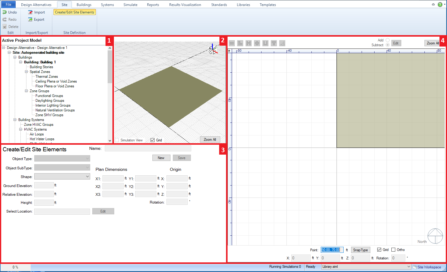
The Site workspace allows the user to develop the neighboring environs (adjacent sites, solar obstructions, etc.) for the BEM, which will shape and influence the results for the building.
Examples - Adjacent Sites - Solar Obstructions - Power Demand - Power Generation

Main Workspace areas:
Active Project Model Tree (top left) - allows the user to see the connections of different components for the project. Serves more as a tool to review connections versus a tool that enables the simulation workspace
Interactive 3d Model View (middle top) - provides the user a 3d interactive view of the current model to preview site objects that are being and/or have been created.
Create Site Objects (bottom left) - the main control panel for adding site objects to the BEM. The first step is to select "NEW" to initiate the process. Next the user will select the desired object type (Adjacent Site, Solar Obstruction, Power Demand, Power Generation, or Solar Surface), which influences what capabilities are exposed in this field. The results of the object sub type and shape selections will start to appear in the 3d view and 2d view once they are selected. The location can be adjusted by entering X and Y values in the Origin column on the right side of the field. The object is not a part of the BEM until Save is selected.
Overall 2d View (right) - displays the 2d view of the base floor plan or any of the available floor plans selected from the project component tree or the interactive 3d view. If spaces have been defined in the model they will be displayed (core and perimeter spaces differ in color). The 2d view is active when the user is creating site elements to either visually preview the object that is being created or if freeform has been selected it is the canvas on which the user draws the custom form. The user has a number of other controls such as direct entry and reporting of X, Y and Z values, the ability to change the orientation, snap, grid and background color controls, as well as the ability import and manipulate the visible layers for a DWG/DXF file.
The Ribbon includes three sections:
______________________________________________________________________________________
© Copyright 2013 Simergy, Sustainable IQ, Inc.