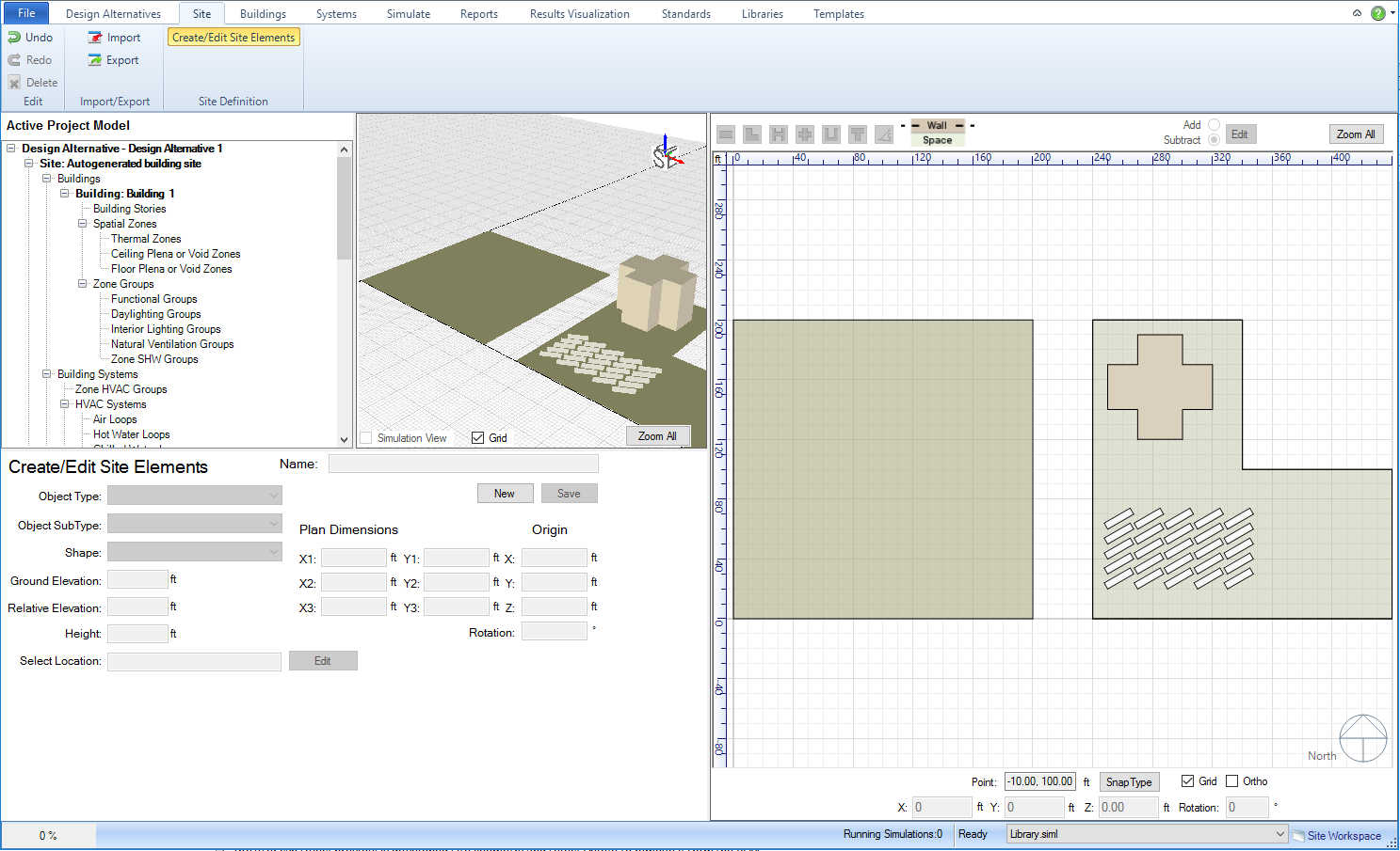
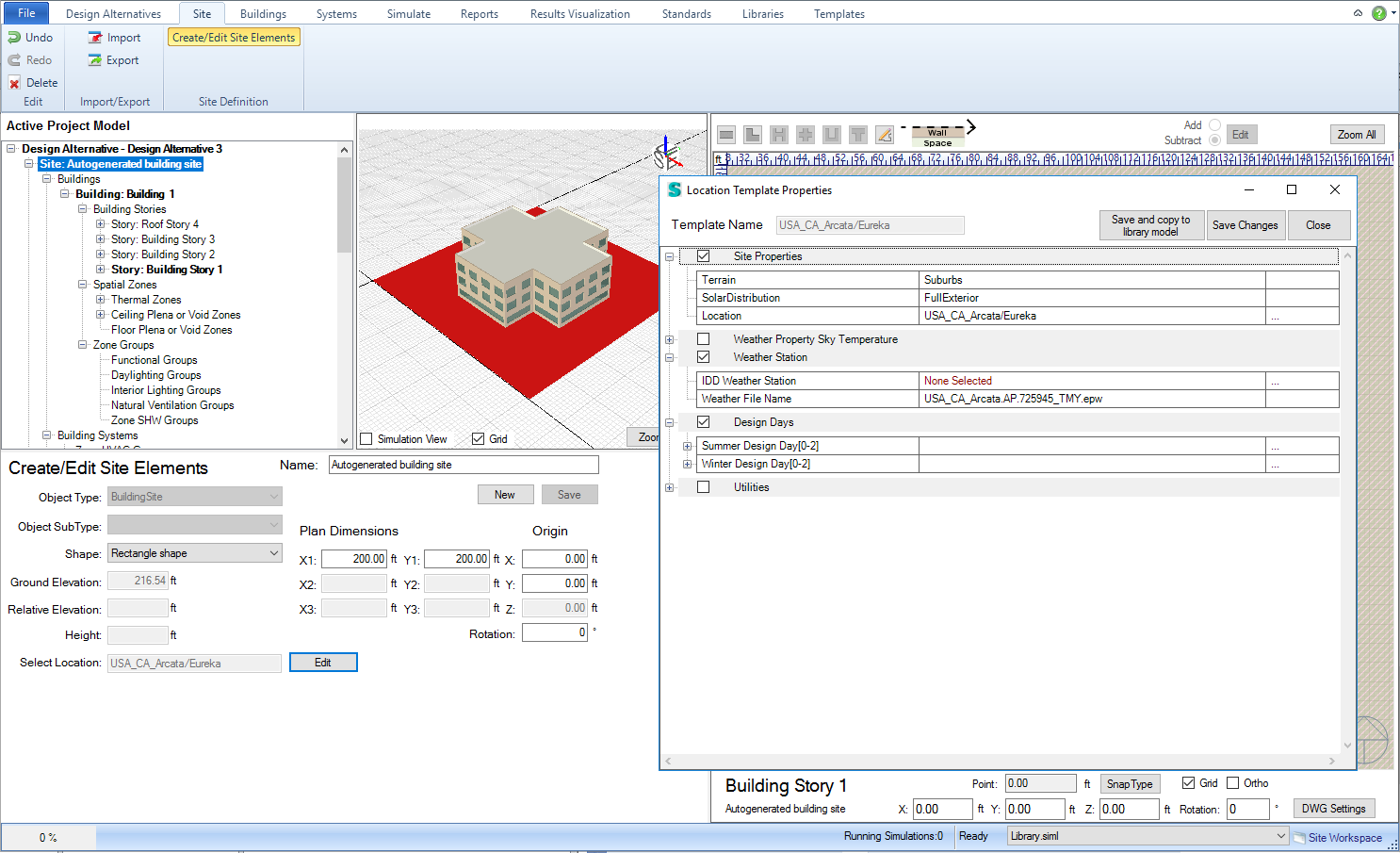
Workspace: Site/ Site Definition/Create-Edit Site Elements
Workspace Area Links - Active Project Model Tree - 3d view - 2d view
Examples - Adjacent Sites - Solar Obstructions - Power Demand - Power Generation - Solar Surface
The first step to starting the process of creating site elements is to click "New". This activates different features within this tab.
Note: The user can start to create geometry without selecting New, however they will reach a point where they cannot go further and will have to start over by selecting New.
Once the user feels the preview and the input selections are acceptable they can select Save to incorporate the site elements and geometry into the BEM. At this point the site geometry has been incorporated into the model, but the overall Simergy model file has not been saved.
The field is where the user can enter a name for the site element or geometry they are creating or they can use the default naming. The name entered into the Name field is the one that will appear in the Active Project Model once the site element or geometry has been saved. The table identifies the default naming for the different object types. If more than one of the same object types are created a unique name is provided to each object by sequentially increasing the number by one associated with the default name.
| Object Type | Default Name |
| Adjacent Site | Adjacent Building Site 1 |
| Solar Obstruction | Solar Obstruction 1 |
| Power Demand | Power Demand 1 |
| Power Generation | Power Generation 1 |
Solar Surface |
Solar Surface 1 |
Defines the site object type that the user will incorporate into the project, and establishes what object sub types are available for selection. The object types available include:
| Object Type | Description |
| Adjacent Site | a geometry representation that can provide context for the neighboring environment |
| Solar Obstruction | 3d geometry that can be constructed to represent neighboring buildings or obstructions that will influence the solar exposure of the project. |
| Power Demand | External objects to the building model that are potentially demand sources for building resources |
| Power Generation | External objects that are generators contributing energy to the building |
Solar Surface |
An array of panels that collect sunlight to contribute energy to the building |
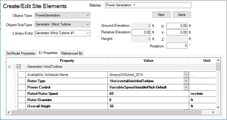
Note: The workspace area changes based on what Object Type is selected. An example for Power Generation is below. Each Object Type example includes an image of the workspace area. Fields shown with a gray background cannot be edited directly. In most cases the user will be required to go to the Libraries Category to edit this property.
The table displays the object types, associated object sub types and the shape options that are available.
Note: The object Sub Types have links to the EnergyPlus documentation for the object.
| Object Types | Object Sub Type | Shape |
| Adjacent Site | No Sub Types | Rectangle, L-Shape, T-Shape, Free Form |
| Solar Obstruction | Building Shading
Building Shading Detailed Site Shading Site Shading Detailed |
Rectangle, L-shape, H-shape, Cross-shape, U-shape, T-shape, Free form |
| Power Demand | Exterior: Lights
Exterior: Water Equipment |
Not Applicable |
| Power Generation | Generator:
Internal Combustion Engine
Generator: Combustion Turbine Generator: Photovoltaic Generator: Micro CHP Generator: Micro Turbine Generator: Wind Turbine |
Not Applicable |
| Solar Surface | Solar PV Array
Solar HW Array |
Not Applicable |
When a sub type is selected for Power Demand and Power Generation Site Objects a property table is displayed, which is the same table composition the user will see in the Libraries workspaces.
The shape options for each Object Type and Sub Type combination are shown in the table above.
Note: for Power Demand and Power Generation Site Objects
Once an Object Type and Object Sub Type are entered the user can select a Library Entry that is available from the drop down list, which will populate the associated Properties table.
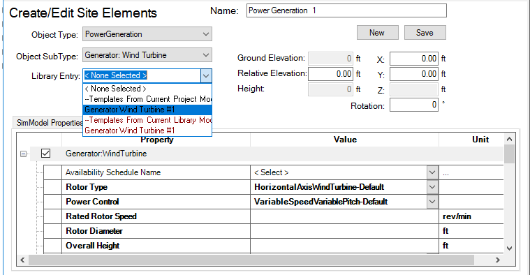
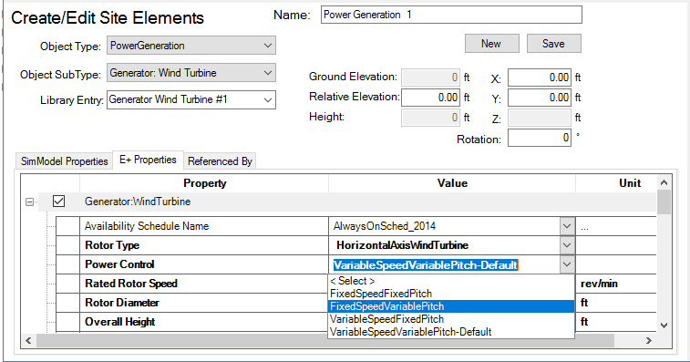
The user can make edits to the Library entry directly in the Properties table (see image below), which will be applied to the Site Object once Save has been selected. See Example - Power Demand Site Object and Example - Power Generation Site Object.
Note: If the user has made changes to the Library Entry they will not be saved with the Site Object until the Site Object has been Saved incorporating it into the model. The user cannot make changes to a Library Entry in this table and Save them to the Source Library.
If the user wants to create their own Library Entry for Power Demand and Power Generation Site Objects, they can do so in the following Libraries Workspaces:
The base elevation for the project model. It can be edited by going to Libraries/Location Specific/Locations, but it cannot be directly edited in this workspace.
The elevation that can be defined for the site object that is being created. Default = 0 ft (units can be changed in File Options)
The height of a site object that can be specified for the Solar Obstruction Site Object Type.
Note: Not active unless a Site Object has been selected (see image below)
A drop down list displaying the weather file locations that are associated with the project model.
Note: Not active unless a Site Object has been selected (see image above)
Selecting Edit launches a pop-up dialog displaying the Location Properties Template. The user can make edits and Save changes to the Location Template within the Project Model Source Library.
The set of fields that allow the user to set the size of different Site Object Types. See Example - Solar Obstructions.
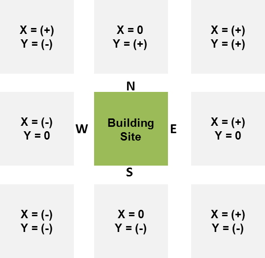
The origin point for the site the Site Object can be entered in the X, Y and Z fields (if applicable). See diagram below for X and Y origin values (positive, negative or 0) based on location to the building site.
The user can enter a value between 0 and 360 to set the orientation of the model. Entering a value in the field and then selecting elsewhere associates that value with the model and the north arrow in the 2d view will adjust to correspond. The 0 to 360 degrees range is in a clockwise direction where 180 deg. = South, 225 deg. = Southwest, and so on.
______________________________________________________________________________________
© Copyright 2013 Simergy, Sustainable IQ, Inc.