Case Study 1: Mixed-Use Building
Description: A mixed-use building project with (2) stories of underground parking, (2) stories of retail with an interior courtyard, and (2 x 3) story office towers. Each occupancy (parking, retail, office) is modeled as a Building Section using the appropriate Loads & Conditions template for that occupancy.
HVAC Systems: Heating and cooling is provided by radiant active beams and fresh air is provided by Dedicated Outdoor Air Systems (DOAS).

Figure 1: 3D view of the building geometry
Internal loads: Internal loads are all set to a school building divided into the 3 building sections.
| Internal load type | Value | Weekday | Saturday | Sunday |
| People | 2.32 m2/person 24.97 ft2/person |
 |
 |
 |
| Lights | 12.92 W/m2 1.2 W/ft2 |
 |
 |
 |
| Electrical Equip. | 10.98 W/m2 1.02 W/ft2 |
|
|
|
| Thermostat type | Min/Avg/Max | Weekday | Saturday | Sunday |
| Heating Schedule | 16.0/17.2/19.0 C 60.8/62.5/66.2 F |
 |
 |
 |
| Cooling Schedule | 26.0/28.1/29.4 C 78.8/82.8/85.0 F |
|
|
|
HVAC: The building is equipped with an active beam system that provides cooling and heating (as needed) in an efficient manner due to the reduced size of the air system.
The air loop is a DOAS system with heat recovery and DX cooling and gas heating. This case study uses non-water based heating in the air loop to reduce the need for a two different hot and chilled water loops. The active beams use lower hot and hotter cold water supply temperatures than air loop coils would. The active beams are connected to two water loops (hot and cold) as well as a condenser loop
| Air loop | 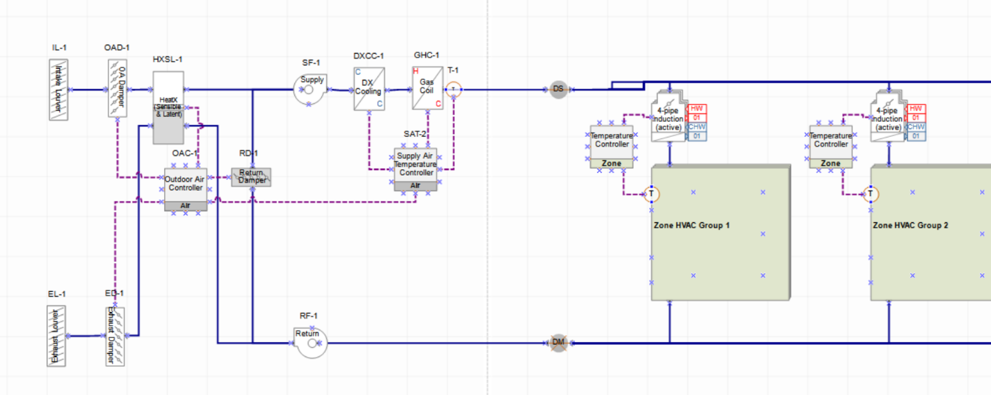 |
Chilled water loop | 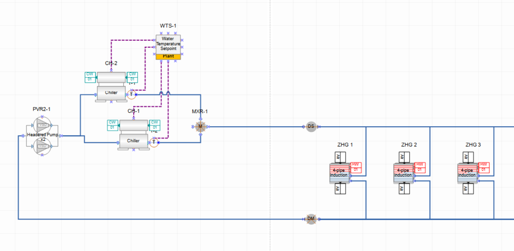 |
| Hot water loop | 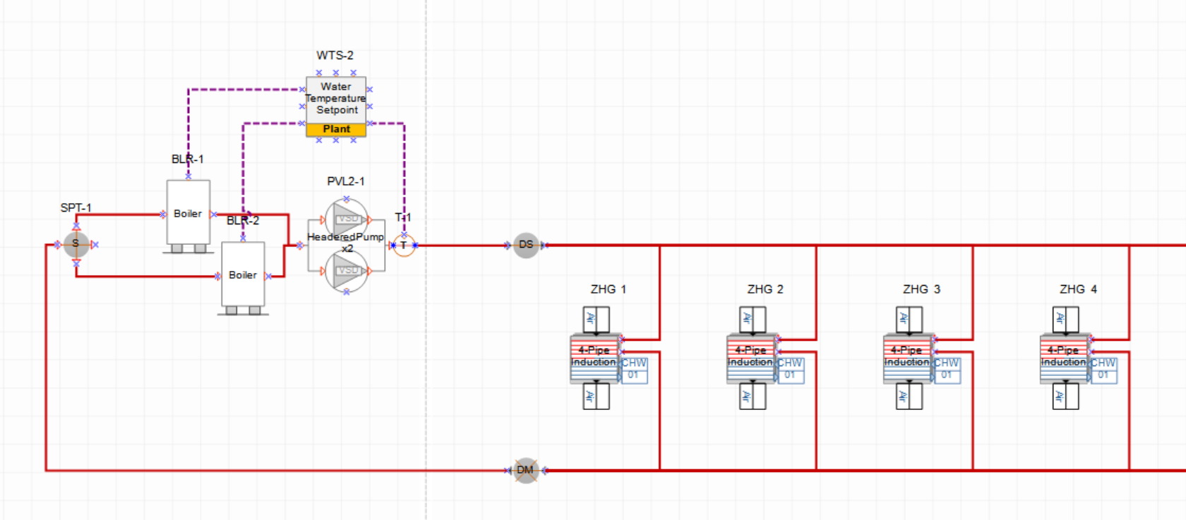 |
Condensor loop | 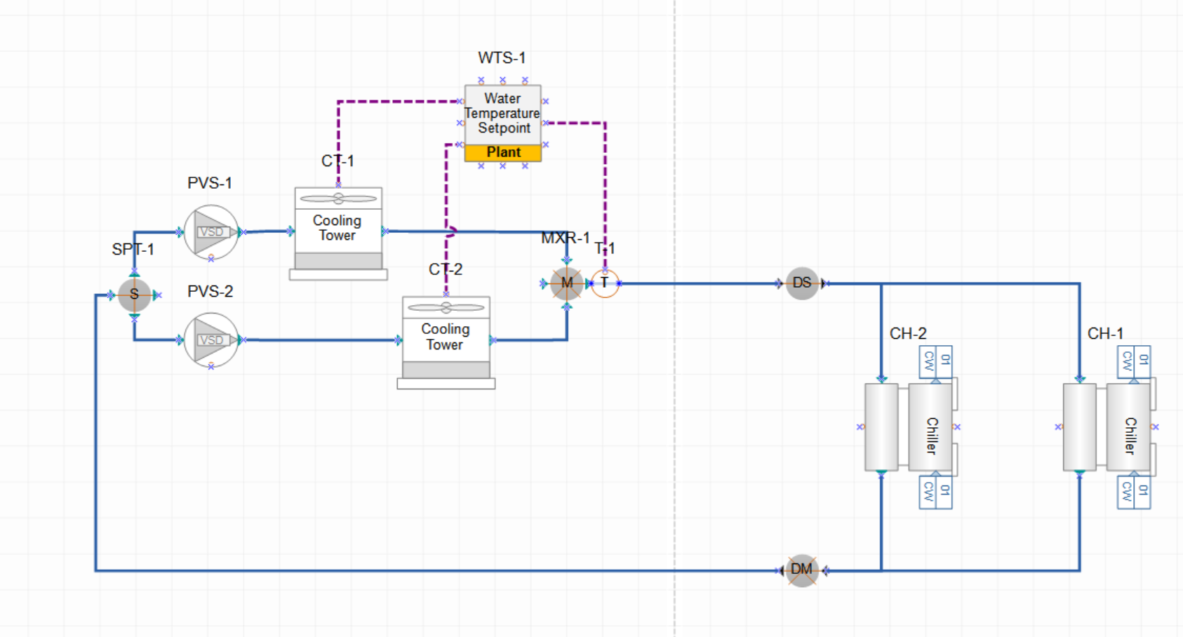 |
Figure 2: Air and water loop diagram overview (click any image to enlarge)
Control and temperatures: The air loop as a DOAS system is controlled at a supply air temperature of 15 C/ 59 F. Due to the lower hot water temperature (26.67 C/80 F) and hotter cold water temperature (10 C/ 50 F) for the active beams the two water loops run on more efficient temperatures than regular water loops. The condenser loop is controlled based on outside air temperature.
Results: compared to an ASHRAE-7 system (VAV reheat air terminals with water based cooling and heating, hot water loop with 2 boilers, chilled water loop with two chillers and a condenser loop with 2 cooling towers). The “Energy End Use Summary” report highlights the difference between the two systems at an end use breakdown. You can see that the air flow is reduced as well as the heating and cooling energy. Internal loads however are as expected the same.

Figure 3: Comparing Page 3 of Project Summary report: “Energy End Use Summary”
The air flow graphic below shows outside air flow fraction indicating that the active beam system is a 100 % outside air system (Or DOAS). The lower graph shows the Fan Electric Energy also showing the constant and lower air flow of the active beam variant.

Figure 4: Outside air flow fraction and fan electric consumption
DisplayOrder: 1