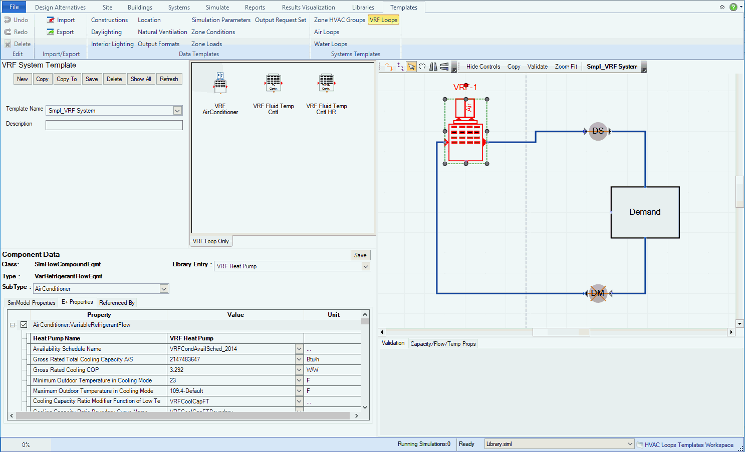

System Template Naming/Selection Area - the drop down list where the templates from the active source library can be selected, and descriptions can be associated with each template as well.
Chilled Water Loop Parameters Area - the properties that can be set at the overall loop level
Component Properties - the properties that appear in the lower left when a component shape is selected in the HVAC Diagramming Canvas
Stencils - include the component, controller and sensor shapes that can be dragged and dropped onto the HVAC Diagramming Canvas to create or edit the templates
HVAC Diagramming Canvas - the loop creation playground where the component shapes can be dragged and dropped onto, different components can be connected, components selected to edit properties and other features.
Loop Level Controls - displays the current Plant Operation Schemes and Availability Managers that are defined for the template.
Validation - The location where the error messages are displayed after the Chilled Water Loop Ruleset has been run (Validate)
The table displays the Chilled Water Loop System Templates that are included with version 1. The Chilled Water Loop System Templates utilize a naming convention, so that the names can be represented in an abbreviated manner.
Note: Chilled water templates can be edited and resaved or copied, edited and saved as new templates.
VRF Loop System Templates |
Full Name & Description |
| Smpl_VRF_System |