
Radiant Systems refers to a range of different radiant heating, radiant cooling and/or radiant heating and cooling system types. Radiant Systems are typically hydronic (fluid based) and system configurations can vary starting from the source (how the fluid is conditioned, such as with a ground source heat pump) to the radiant components used in the space (surface or panel).
The basic premise of radiant systems is:
[include diagrams]
Radiant system configurations can get more complex for systems that are providing both radiant heating and radiant cooling.
The energy savings potential of radiant systems are based on the premise that pumping fluids to surfaces and panels to condition occupants is more efficient than conditioning air with coils and distributing with fans. These systems tend to be combined with a Dedicated Outdoor Air System (DOAS), which separates ventilation from occupant conditioning, which is another different from typical air based systems. Radiant systems are climate dependent, do not have infinite capacity, and the savings that can be realized is dependent on the radiant systems integration within the overall design. As a number of building design precedents have shown, an efficient radiant system starts at the building envelope. The more extremes in terms of loads, such as direct sunlight, that can be reduced from the equation, the better the operating conditions for a radiant system. Another key design consideration is how quickly is the heating or cooling required? Radiant Systems can incorporate thermal mass....
Let's start by taking a close look at one of the sample projects included with the Simergy installation, ASHRAE-7_V19_DA_RadSlab, which can be found at C:\Users\Public\Simergy\Samples\Sample_Projects. The project contains two design alternatives. The first, titled "Baseline Design", is a baseline design for ASHRAE System 7, and the inputs are influenced by the location (Minneapolis, MN) associated with this file. The second, titled "RadFloors", is a radiant system alternative for the ASHRAE System 7 configuration. We will be focusing primarily on this design alternative, and we'll start by taking a look at the Zone HVAC Groups.
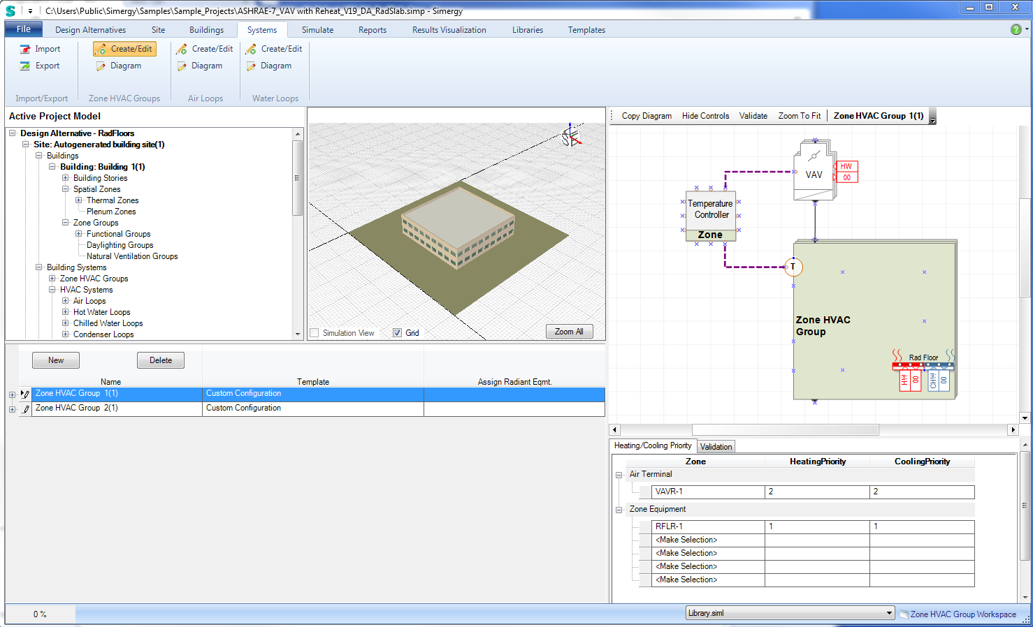
Zone HVAC Group Create/Edit workspace for Design Alternative 2 - RadFloors showing Zone HVAC Group 1 that contains a Radiant Floor object.
When laying out a radiant system in Simergy it is important to have the full system configuration in mind, and it is best to start at the zone level. Setting up a Radiant System in Simergy in a lot of ways is no different than setting up another type of HVAC system. We'll walk through the six different Systems Workspaces that are important to the system configuration and go through the process steps what needs to be and can be done when settting up a Radiant System. We'll use the sample project as the basis for the discussion.
In this sample project, the radiant component introduced at the Zone HVAC Group level is the Radiant Floor, which in this case will be linked to both hot and chilled water loops. It is a radiant slab that provides the ability to heat or cool the space with the floor surface. To access and edit the properties of the radiant floor component, you will need to go to the ZoneHVAC Group (ZHG) diagram workspace.
Note: The water loop reference tags are displaying "00", which means they have not been assigned to hot water loop. Once the water loops have been set up and the ZHG associated with an Air Loop, then the radiant floor component can be assigned to the relevant water loops.
A couple of other features to note to within this workspace:
You will primarily use this workspace to edit the properties for any of the components within the ZHG and/or if you want to add additional components.
Note: Making changes in the diagram workspace does not change the ZHG Template (if one was selected) that is stored in the library, it only changes the instance of the ZHG template used in the model.
For additional information on the Radiant Floor and Radiant ceiling components and the properties associated with each see Radiant Devices.
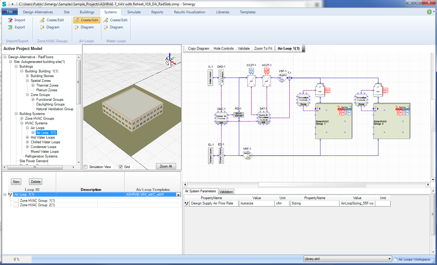
Air Loop configuration for ASHRAE-7_VAV with Reheat_V19_DA_RadSlab with Radiant ZHGs assigned
The process for setting up what is displayed is:
Within the table on the lower left, select NEW to create a new Air Loop. A new row will appear with a default name, and in the HVAC Diagramming area a simple demand box will appear.
Select an Air Loop Template from the drop down list in the third column. Once a selection has been made the supply side configuration for the Air Loop will be displayed. In this case ASHRAE-VAV_wtrC_wtrH was selected, which is a variable air volume configuration with hot water and chilled water coils with inputs in-line with the ASHRAE requirements. If you have an interest in taking a closer look at this template, you can view it directly by going to Templates>System Templates>Air Loops and select the template from the available set.
Typically when an Air Loop Template is selected, it will already have Air System Parameters assigned, and if you would change them you can do it in one of three ways:
In this case the Design Supply Air Flow Rate is set to Autosize and the Sizing libraries entry selected is AirLoopSizing_55F-cooling_65F-heating, which has the following properties and input values:
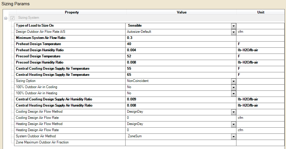
Sizing Parameters for AirLoopSizing_55F-cooling_65F-heating (source: Libraries>Controls and Performance Data>Sizing Params - - Type = HVACDesign; Sub Type = AirLoopSizing)
Now we are ready to define the Demand side of the Air Loop. In this case, the Active Project Model tree was expanded to show the Zone HVAC Groups that were created, which were highlighted (holding shift down allows multiple selections) and then dragged to the Loop ID table and dropped on Air Loop 1. This process of defining the demand side results in the Zone HVAC Groups now being displayed on the right side (demand side) of the Air Loop diagram.
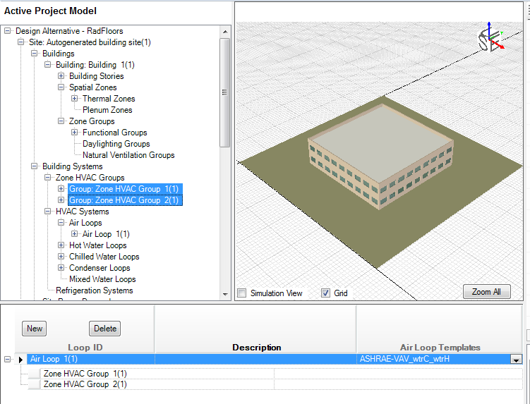
Portion of Zone HVAC Group Create/Edit workspace for ASHRAE-7_VAV with Reheat_V19_DA_RadSlab, highlighting how Zone HVAC Groups can be highlighted in the Active Project Model tree and then dragged and dropped to associate them with an Air Loop
A good practice is to Validate each air or water loop as they are created. You can do this by selecting Validate from the options across the top of the HVAC diagramming area. Once Simergy has run the validation the "System Issues to be fixed" will be displayed in the table below the HVAC diagramming area (Note: the Validation tab becomes highlighted vs. the Air System Parameters tab), and the Error Type will be displayed as well.
Once you've set up and validated the loop, you may find that you either want to:
If the answer to any or all of the above is "Yes", then you'll need to go to the Diagramming Workspace.
In the Air Loop diagram workspace to can do any of a number of different things to edit and change the Air Loop diagram. You can add new components, change the properties of individual components by selecting them, and add Loop Level Controls. Since the other features are covered in depth elsewhere, we are going to focus on the last feature, setting up Loop Level Controls.
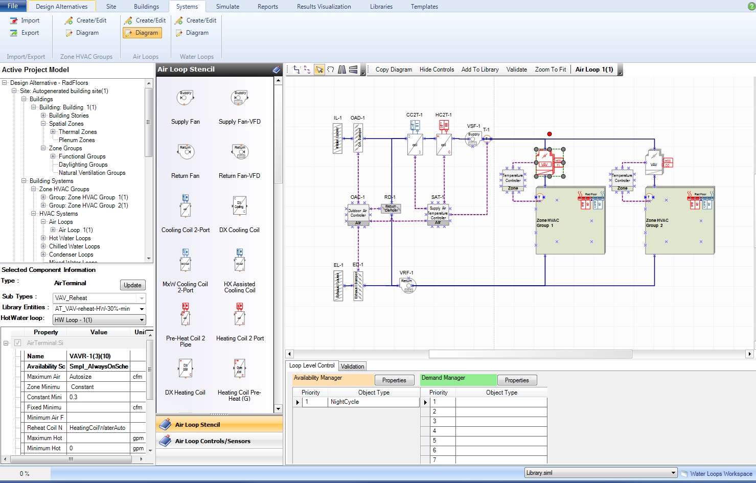
Air Loop diagram workspace for ASHRAE-7_VAV with Reheat_V19_DA_RadSlab.
See Loop (System) Level Controls for a more detailed description of the different types and options of Loop Level Controls that are available. To setup or change the Loop Level controls for either the Availability Manager or Demand Manager, you need to select the Properties button to launch the dialog box that allows you to select the Object Type and the relevant scheme for the desired priority configuration.
Loop Level Controls for Air Loop diagram workspace for ASHRAE-7_VAV with Reheat_V19_DA_RadSlab.
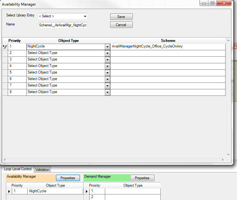
In this case only one Availability Manager has been associated with the Air Loop, the NightCycle. On the surface this seems simple enough and when you open the dialog box you also see that the Scheme select for the night cycle is the "AvailManagerNightCycle_Office_CycleOnAny" library entry. However you need to know that to change the input values that drive these controls you are going to need to go a few different places:
To change the input values for this scheme you need to go to - Libraries>Controls and Performance Data>Control Schemes
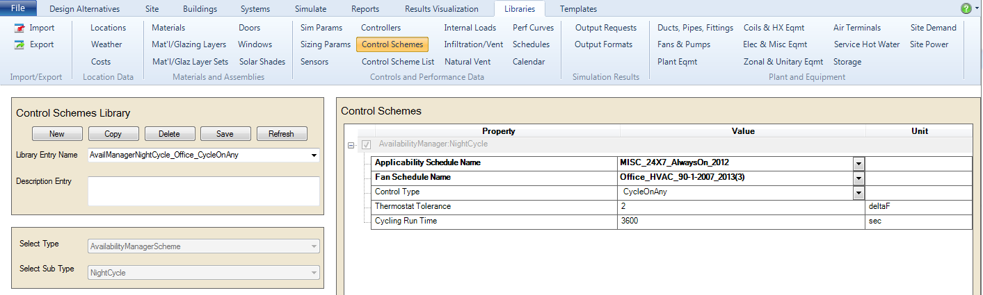
Libraries Control Scheme for AvailManagerNightCycle_Office_CycleOnAny
The EnergyPlus Input Output reference describes the properties for the NightCycle Availability Manager in more detail:
This manager is used for cycling on an air system when one or more zones become too hot or too cold. The usual situation is that the central air handler is turned off at night. However if the building gets too cold there might be condensation on the walls and other damage. Thus the control system is usually programmed to turn the system on if 1 control thermostat or any thermostat shows a zone temperature of less than a night time set point. Similarly there might be a concern about a building getting too hot. Again the control system is programmed to turn the air handler back on if one or any zone temperature exceeds a night time cooling set point.
This object gives the user considerable flexibility in determining how the night time on/off decision will be made. The manager can look at the temperature in 1 zone or it can sample all the zones connected to the air handler. The user can specify a temperature tolerance and a run time for the system once it switches on. There is also an applicability schedule – the user can schedule whether or not this availability manager itself is being applied.
If you look at the first two input rows you see that there are two schedules associated with this control scheme, and that if you want to edit or review these you will need to go to the source of the schedules.
To get to the Schedules, you need to select Libraries>Controls and Performance Data>Schedules. You will be prompted by a dialog box. Select Schedule Editor.
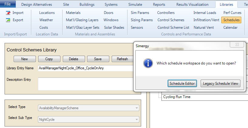
Libraries>Schedules initial dialog box
Now you will be taken to the Schedule Editor workspace. Here you can locate the two schedules mentioned to review and make edits as needed. Once the changes are made they will be updated within the BEM.
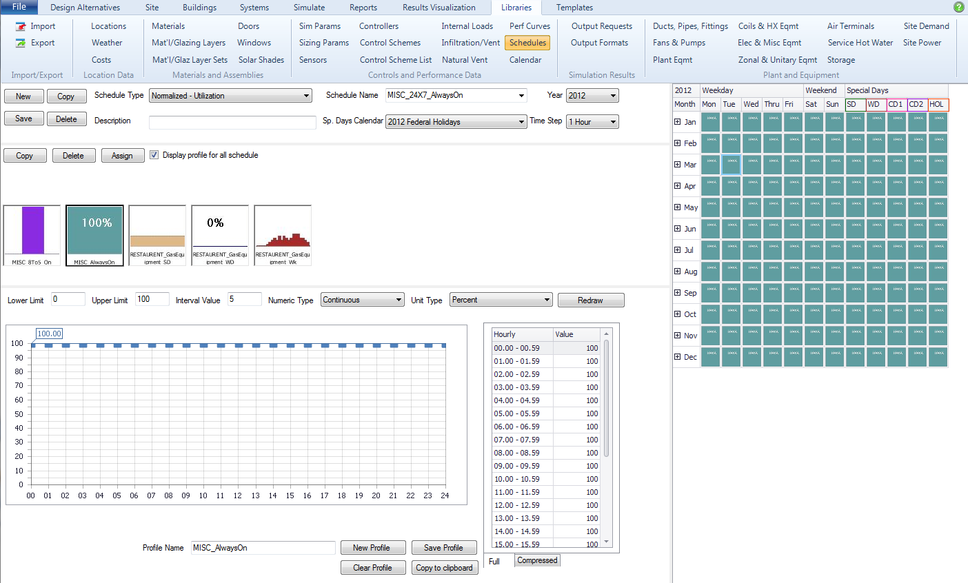
Libraries>Schedules>Schedule Editor Workshop Space - the utilization schedule (MISC 24x7 AlwaysOn) is displayed
It is worth reviewing the Schedule Editor workspace in more detail to understand how edits can be made to the schedule, but the important thing to remember is that these schedules play an important role in defining how the Availability Manager will operate within your BEM, and therefore you should know what the schedules are!
Hopefully even from this simple example, you can see there is a great deal of flexibility and capabilities within Loop Level Controls, but to utilize them effectively you will need to be rigorous in how you set up and review the inputs and schedules that are associated with them.
To effectively model radiant systems it is recommended that you set up two sets of water loops. One set for the radiant components, and a another set for the other system components.
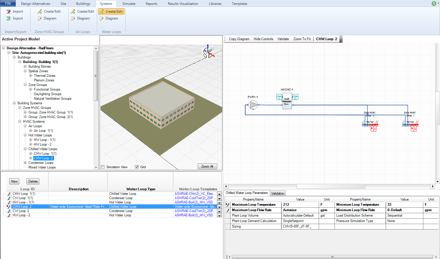
Water Loop Create/Edit Workspace for ASHRAE-7_VAV with Reheat_V19_DA_RadSlab, Chilled Water Loop 2 (radiant components)
For the sample project the first three rows in the Loop ID table (bottom left) are for the other system components, and the bottom three rows are for the radiant components. The Water Loops workspace is set up in a similar fashion to the Air Loop Create/Edit workspace and the Loop Parameters and Validation tables are located on the bottom right of the workspace.
Let's take a look at CHW Loop 2, which is the chilled water loop associated with the radiant panels. A couple of things to note:
We'll stay with CHW Loop 2 as we look at the diagram workspace
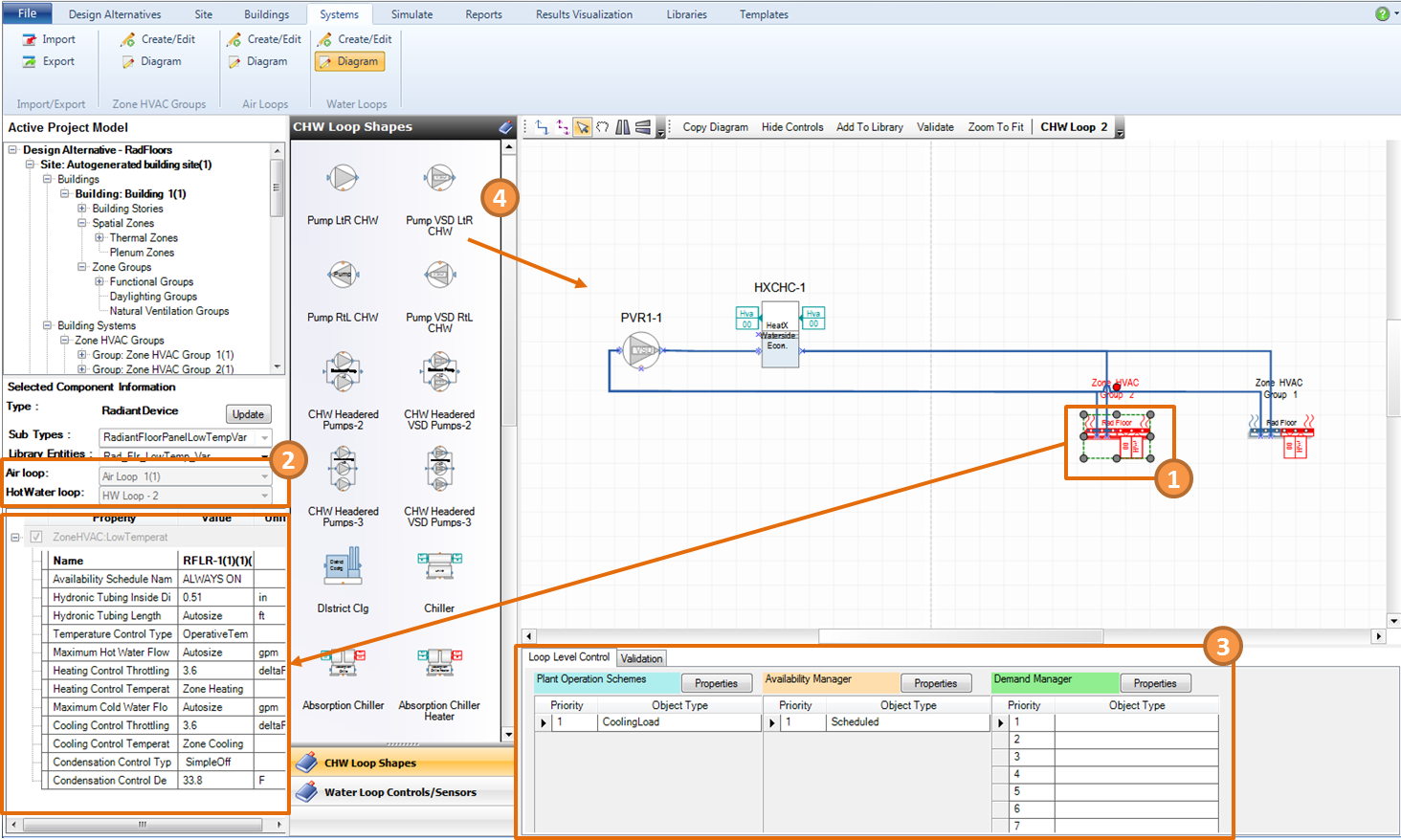
Water Loop Diagram Workspace for ASHRAE-7_VAV with Reheat_V19_DA_RadSlab, Chilled Water Loop 2 (radiant components)
The image highlights a few key things:
As with the Air Loop diagram workspace the Water Loop Diagram space is where you can set up the Loop Level controls. In addition to Availability Managers and Demand Managers, Plant Operation Schemes can also be setup. As with the other control types they can be accessed by selecting the Properties button and in this case you are selecting an Object Type, Scheme and a Schedule versus having the schedule be a property within the scheme.