Stencil: Zone HVAC Stencil: Radiant Ceiling
Type: Radiant Device
Sub Type: Different Options
![]()
Stencil: Zone HVAC Stencil: Radiant Floor
Type: Radiant Device
Sub Type: Different Options
![]()
Note: Requires a connection to a chilled water loop and a hot water loop
EnergyPlus Object - AirTerminal:SingleDuct:ConstantVolume:FourPipeInduction
Note: The property information is the same for both components. The user selects which type with the Sub Types drop down list.
When the user is in the Zone HVAC Groups Diagram workspace or the Air Loops Diagram Workspace and they select a Radiant Device component shape, the following properties will be displayed in the lower left section of the workspace.
The Radiant Device Sub Type options include:
RadiantClngPanelLowTempVarFlow
RadiantFloorPanelLowTempVarFlow
RadiantClngPanelLowTempConstantFlow
RadiantFloorPanelLowTempConstantFlow
RadiantClngPanelHighTemp
RadiantFloorPanelLowTemp_Electric
RadiantClngSlab_Ventilated
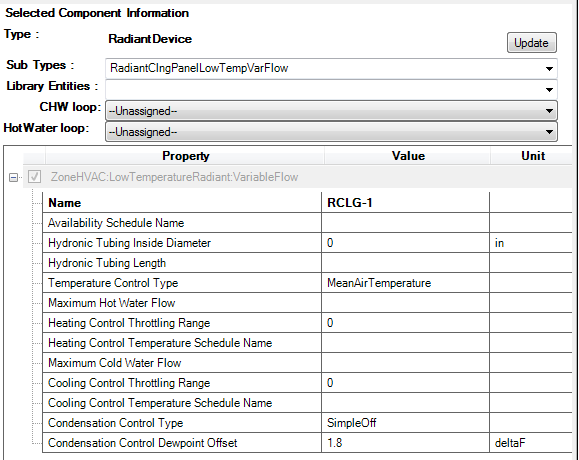
Figure - Simergy Component Properties Table
The properties in bold are required Value Entries or selections.
Simergy automatically defines a unique name for each component. This can be changed by the user if desired.
The availability is established by selecting an available library entry from the drop down list. The source for the options listed is Libraries:Schedules:Schedule Editor:Availability Schedules (Schedule Types)
This field is the inside diameter of the tubes through which water is circulated for the system being defined by this statement. The inside diameter should be recorded in meters and is used to determine the convective heat transfer from the water to the inside surface of the hydronic tubing.
This field is the total length of pipe embedded in the surface named above in the surface name field. The length of the tube should be entered in meters and is used to determine the effectiveness of heat transfer from the fluid being circulated through the tubes and the tube/surface. Longer tubing lengths result in more heat will be transferred to/from the radiant surface to the circulating fluid. Note that if the user elects to autosize this field that a standard zone thermostat such as would be used for a forced air system must be defined as autosizing calculations are based on the zone thermostat value and not on the radiant system control values.
This field specifies along with the throttling range and setpoint schedules how the user wishes to control the hydronic radiant system. The temperature denoted in the setpoint schedule can refer to one of five different temperatures: the zone mean air temperature, the zone mean radiant temperature, the zone operative temperature, the outdoor dry-bulb temperature, or the outdoor wet-bulb temperature. The choice of temperature is controlled by the current field—temperature control type.
This field is the maximum flow rate of hot water through the radiant system in m3/sec. The controls for the radiant system will vary the flow rate of hot water through the surface using zero flow and the maximum flow rate specified in this field as the lower and upper bounds, respectively. Note that if the user elects to autosize this field that a standard zone thermostat such as would be used for a forced air system must be defined as autosizing calculations are based on the zone thermostat value and not on the radiant system control values.
This field specifies the range of temperature in degrees Celsuis over which the radiant system throttles from zero flow rate up to the maximum defined by the maximum hot water flow rate field described above. The throttling range parameter is used in conjunction with the control temperature to define the response of the system to various zone conditions. The heating control temperature schedule specifies the “setpoint” temperature where the flow rate to the system is at half of the maximum flow rate. For example, if the heating control temperature setpoint is currently 15°C and the heating throttling range is 2°C, the water flow rate to the radiant system will be zero when the controlling temperature (MAT, MRT, Operative Temperature, ODB, or OWB; see control type field above) is at or above 16°C and the maximum flow rate when the controlling temperature is at or below 14°C. This represents a throttling range of 2°C around the setpoint of 15°C. In between 14°C and 16°C, the flow rate to the radiant system is varied linearly.
This field specifies the heating setpoint or control temperature for the radiant system in degrees Celsius. Used in conjunction with the previous field (heating control throttling range), it will define whether or not the system is running and the current flow rate. Water flow rate to the system is varied linearly around the setpoint temperature based on the throttling range and the maximum heating flow rate parameters (see above). It should be noted that this control schedule will allow different setpoint temperatures throughout the year for heating. The control of the radiant system is based solely on the heating control temperature schedule, the cooling control temperature schedule (see below), and the control temperature type listed above. The radiant system will not use any zone thermostat that might be used by other systems serving the zone in which the radiant system resides.
This field is the maximum flow rate of cold water through the radiant system in m3/sec. The controls for the radiant system will vary the flow rate of cold water through the surface using zero flow and the maximum flow rate specified in this field as the lower and upper bounds, respectively. Note that this field is optional and not required for a heating only system. Note also that if the user elects to autosize this field that a standard zone thermostat such as would be used for a forced air system must be defined as autosizing calculations are based on the zone thermostat value and not on the radiant system control values.
This field specifies the range of temperature in degrees Celsuis over which the radiant system throttles from zero flow rate up to the maximum defined by the maximum cold water flow rate field described above. The throttling range parameter is used in conjunction with the control temperature to define the response of the system to various zone conditions. The cooling control temperature schedule specifies the “setpoint” temperature where the flow rate to the system is at half of the maximum flow rate. For example, if the cooling control temperature setpoint is currently 25°C and the cooling throttling range is 2°C, the water flow rate to the radiant system will be zero when the controlling temperature (MAT, MRT, Operative Temperature, ODB, or OWB; see control type field above) is at or below 24°C and the maximum flow rate when the controlling temperature is at or above 26C. This represents a throttling range of 2°C around the setpoint of 25°C. In between 24°C and 26°C, the flow rate to the radiant system is varied linearly.
This field specifies the cooling setpoint or control temperature for the radiant system in degrees Celsius. Used in conjunction with the previous field (cooling control throttling range), it will define whether or not the system is running and the current flow rate. Water flow rate to the system is varied linearly around the setpoint temperature based on the throttling range and the maximum cooling flow rate parameters (see above). It should be noted that this control schedule will allow different setpoint temperatures throughout the year for cooling. The control of the radiant system is based solely on the heating control temperature schedule listed above, the cooling control temperature schedule, and the control temperature type listed above. The radiant system will not use any zone thermostat that might be used by other systems serving the zone in which the radiant system resides.
When radiant systems do cooling, there is the possibility that condensation will occur on the surface that is being cooled. This is due to the fact that the surface temperature may drop below the dew-point temperature of the space. When this occurs, condensation on the surface will occur. In EnergyPlus, users have several options for handling this situation including: Off and SimpleOff. When the user chooses the Off option, EnergyPlus will not do anything other than produce a warning message when condensation is predicted to occur. The program will simply continue on; no moisture will be removed from the zone air and there will be no adjustment of the surface temperature as a result of the condensation. When the user chooses the SimpleOff option, the program will predict cases where condensation will occur and shut-off the radiant system to avoid this situation. With this option, the users also have the opportunity to adjust when the system will shut down. This is specified with the next parameter (field: condensation differential parameter). This parameter is optional and EnergyPlus will use the SimpleOff strategy when this parameter is not specified.
This optional parameter is only valid with the SimpleOff condensation handling algorithm (see previous input parameter). It establishes the difference between the calculated dew-point temperature of the space and the allowed surface temperature to which the surface can drop before the radiant system shuts down in degrees Celsius. This parameter can be any positive, negative, or zero value. When this parameter is zero, the radiant system will shut down when the surface temperature drops to the dew-point temperature or below. When this parameter is positive, the radiant system will shut down when the surface is the number of degrees Celsius above the dew-point temperature. This allows some extra safety to avoid condensation. When this parameter is negative, the radiant system will shut down when the surface temperature is the number of degrees Celsius below the dew-point temperature. While not recommended, this strategy allows the user to simulate a situation where small amounts of condensation are tolerable.
Ventilated slab systems in general use outdoor air to “precool” slabs with colder nighttime air. This method of precooling the thermal mass of a space can be very effective when nighttime temperatures are low and the mass of the system is high enough to provide a significant amount of cooling potential during the day to counteract internal heat gains within a zone.
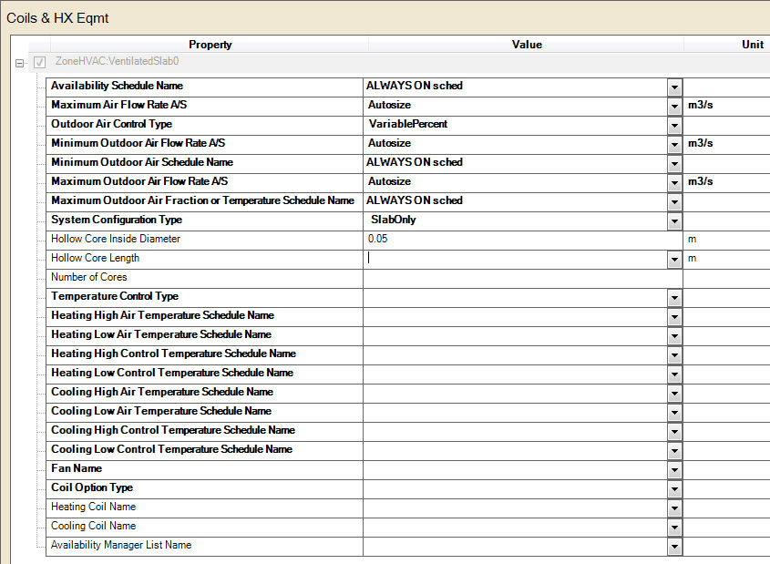
This field is the name of the schedule (ref: Schedule) that denotes whether the ventilated slab system can run during a given hour. A schedule value greater than 0 (usually 1 is used) indicates that the unit is available and can be on during the hour. A value less than or equal to 0 (usually 0 is used) denotes that the unit is not available and must be off for the hour.
This field allows the user to enter the maximum volumetric flow rate of air through the ventilated slab system in m3/sec. This parameter should be some real number greater than zero.
This field allows the user to control how outdoor air is used in the ventilated slab system. The ventilated slab system described by this syntax has its own outdoor air handler. The three options for outdoor air control are “VariablePercent”, “FixedTemperature” and “FixedAmount”. Those keywords are the only allowed choices for this parameter. In general, the variable percent control will attempt to vary the amount of outdoor air between some minimum and maximum schedules of fractions (see next two fields) to best meet the current heating or cooling load. The fixed temperature control will vary the amount of outdoor air between the minimum schedule (fraction of maximum, see next field) and 100% available outdoor air to come as close as possible to a desired mixed air temperature (see two fields down) that can be scheduled. The fixed amount control will fix the outdoor air flow rate as minimum outdoor air flow rate and schedule specified by the user and automatically set the maximum and minimum outside flow rate to be equal by ignoring the maximum outdoor air flow rate. More information on the controls and operation of the ventilated slab are given in the section above (preceding the IDF description).
This field allows the user to enter the minimum volumetric flow rate of outdoor air (in m3/sec) that will be brought in to the ventilated slab. The actual minimum outdoor air flow rate will be this number multiplied by the schedule value from the minimum outdoor air schedule. If “FixedAmount” type is selected as the outdoor air control strategy, the outdoor air flow rate will be fixed at the value of this field and the ventilated slab will automatically set the maximum and minimum outside flow rate to be equal by ignoring the maximum outdoor air flow rate.
This field contains a schedule name (ref: Schedule) that should contain values for the minimum outdoor air used by the ventilated slab system for IAQ or other reasons. Note that if the ventilated slab is scheduled off or if there is no load sensed in the zone that the system will not operate even to achieve the minimum air fraction. However, if the system is operating, it will always bring in at least this fraction of the minimum air flow rate (see minimum air flow rate field above). If “FixedAmount” type is selected as the outdoor air control strategy, the actual outdoor air flow rate will be this number multiplied by the minimum outdoor air flow rate in the field above. The ventilated slab will automatically set the maximum and minimum outdoor air schedule to be equal by ignoring the maximum outdoor air schedule.
This field allows the user to enter the maximum volumetric flow rate of outdoor air that can be brought into the ventilated slab in m3/sec. This parameter should be some real number greater than zero. Note that the value for this parameter may be less than the maximum air flow rate of the ventilated slab and this may affect the maximum fraction of outdoor air within the control strategy defined above. This parameter is an absolute maximum and will supercede any scheduled fraction of the ventilated slab maximum airflow rate. If “FixedAmount” type is selected as the outdoor air control strategy, this field will be ignored and be automatically set to be equal to the minimum outdoor air flow rate specified in the field above.
This field can have one of two meanings depending the type of control selected in the outdoor air control type parameter above. If “VariablePercent” or “FixedAmount” was selected, then this field is a schedule name (ref: Schedule) corresponding to a maximum air fraction schedule. Furthermore, if “FixedAmount” type is selected as the outdoor air control strategy, this field will be ignored and be automatically set to be equal to the minimum outdoor air fraction specified in the field below. Note that this is a fraction of the maximum airflow rate field (see parameter above) for the ventilated slab. If “FixedTemperature” control was selected, then this field is still a schedule name (ref: Schedule), but it corresponds to a schedule of mixed air temperatures that the outdoor air control will try to attain.
This field allows the user to control how the air is circulated using the ventilated slab system.
The options are:This field is the inside diameter of the cores through which air is circulated for the system being defined by this statement. The inside diameter should be recorded in meters and is used to determine the convective heat transfer from the circulated air to the inside surface of the ventilated slab.
This field is the length of core embedded in the surface named above in the surface name field. In other words, this should be the distance that air travels as it through the slab. The length of the hollow core in the slab should be entered in meters and is used to determine the effectiveness of heat transfer from the air being circulated through the cores and the core inside surface. Longer core lengths result in more heat transferred to/from the radiant surface to the circulating fluid.
This field allows the user to specify how many cores there are in the ventilated slab. Air flow will be divided equally among the different cores.
This field specifies along with the throttling range and setpoint schedules how the user wishes to control the ventilated slab system. The temperature denoted in the settemperature schedule can refer to one of seven different temperatures: the zone mean air temperature, the zone mean radiant temperature, the zone operative temperature, the surface temperature of the ventilated slab, the outdoor dry-bulb temperature, the outdoor wet-bulb temperature, or the dewpoint temperature of zone mean air temperature. The choice of temperature is controlled by the current field—temperature control type. The user must select from the following options:
Mean Radiant Temperature
Operative Temperature
Outdoor Dry Bulb Temperature
Outdoor Wet Bulb Temperature
Surface Temperature
Zone Air Dew Point Temperature
If the user does not select a control type, MeanAirTemperature control is assumed by EnergyPlus. See the control temperature schedule fields below for more information.
This field specifies the high air temperature in degrees Celsius for the temperature control of a ventilated slab system. Air and control temperatures for heating work together to provide a linear function that determines the air temperature sent to the ventilated slab. The current control temperature (see Temperature Control Type above) is compared to the high and low control temperatures at the current time. If the control temperature is above the high temperature, then the inlet air temperature is set to the low air temperature. If the control temperature is below the low temperature, then the inlet air temperature is set to the high air temperature. If the control temperature is between the high and low value, then the inlet air temperature is linearly interpolated between the low and high air temperature values.
This field specifies the low air temperature in degrees Celsius for the temperature control of a ventilated slab. For more information on its interpretation, see Heating High Air Temperature Schedule above.
This field specifies the high control temperature in degrees Celsius for the temperature control of a ventilated slab. For more information on its interpretation, see Heating High Air Temperature Schedule above.
This field specifies the low control temperature in degrees Celsius for the temperature control of a ventilated slab. For more information on its interpretation, see Heating High Air Temperature Schedule above.
This field specifies the high air temperature in degrees Celsius for the temperature control of a ventilated slab system. Air and control temperatures for cooling work together to provide a linear function that determines the air temperature sent to the ventilated slab system. The current control temperature (see Temperature Control Type above) is compared to the high and low control temperatures at the current time. If the control temperature is above the high temperature, then the inlet air temperature is set to the low air temperature. If the control temperature is below the low temperature, then the inlet air temperature is set to the high air temperature. If the control temperature is between the high and low value, then the inlet air temperature is linearly interpolated between the low and high air temperature values.
This field specifies the low air temperature in degrees Celsius for the temperature control of a constant flow cooling radiant system. For more information on its interpretation, see Cooling High Air Temperature Schedule above.
This field specifies the high control temperature in degrees Celsius for the temperature control of a constant flow cooling radiant system. For more information on its interpretation, see Cooling High Air Temperature Schedule above.
This field specifies the low control temperature in degrees Celsius for the temperature control of a ventilated slab system. For more information on its interpretation, see Cooling High Air Temperature Schedule above.
This field is the name of a fan (ref: Fan:ConstantVolume) that is part of the ventilated slab system. This name links the ventilated slab to particular fan data entered elsewhere in the input data file. A fan name is required since it is the prime mover of air in the ventilated slab system.
This field allows the user to specify the coil operating options as one of the following options:
If None is selected, the ventilated slab does not have any coils, and any other input will be ignored.
If either Heating or Cooling is selected, only a heating or cooling coil, respectively, is present. Thus, only four more inputs will be expected.
If HeatingAndCooling is selected, both heating and cooling coil input must be entered, and the ventilated slab will have both a heating and a cooling coil.
This field is the name of the heating coil that is part of the ventilated slab system. It is assumed that there is always some sort of heating coil associated with a ventilated slab system. This name links the ventilated slab to particular heating coil data entered elsewhere in the input data file.
This field is the name of the cooling coil that is part of the ventilated slab system. It is assumed that there is always some sort of cooling coil associated with a ventilated slab system. This name links the ventilated slab to particular cooling coil data entered elsewhere in the input data file.
______________________________________________________________________________________
© Copyright 2013 Simergy, Sustainable IQ, Inc.