Location = Templates/System Templates/Water Loops
Portions of the cooling side of the HVAC system can be provided by the loop configuration of the chilled water loop(s). A complete chilled water loop is composed of a supply side and a demand side. The supply side is composed of different component shapes that are connected together and contain the required properties so that EnergyPlus can run effectively. In addition, controllers can be connected to a number of different components, which allows a range control types and schemes to be introduced into the water loop. When working in the chilled water loop template workspace you can create the supply side of the chilled water loop. Once an chilled water loop template has been saved to the source library it is an option for you to select when you are creating a chilled water loop in your model in the Systems: Chilled Water Loops Create/Edit workspace. The demand side of the chilled water loop can only be created in the Systems:Diagram workspaces. It cannot be created in the Templates workspace and saved with a Chilled Water Loop Template.
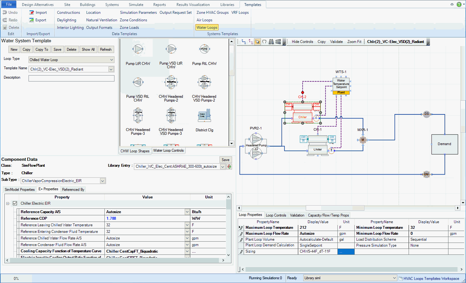
System Template Naming/Selection Area - the drop down list where the templates from the active source library can be selected, and descriptions can be associated with each template as well.
Chilled Water Loop Parameters Area - the properties that can be set at the overall loop level
Component Properties - the properties that appear in the lower left when a component shape is selected in the HVAC Diagramming Canvas
Stencils - include the component, controller and sensor shapes that can be dragged and dropped onto the HVAC Diagramming Canvas to create or edit the templates
HVAC Diagramming Canvas - the loop creation playground where the component shapes can be dragged and dropped onto, different components can be connected, components selected to edit properties and other features.
Loop Level Controls - displays the current Plant Operation Schemes and Availability Managers that are defined for the template.
Validation - The location where the error messages are displayed after the Chilled Water Loop Ruleset has been run (Validate)
The table displays the Chilled Water Loop System Templates that are included with version 1. The Chilled Water Loop System Templates utilize a naming convention, so that the names can be represented in an abbreviated manner.
Note: Chilled water templates can be edited and resaved or copied, edited and saved as new templates.
Chilled Water Loop System Templates |
Full Name & Description |
| ASHRAE-Chlr(2)_VC_Elec_EIR_VS | |
ASHRAE-Chlr(2)_VC_Elec_VS |
|
Chlr(1)_VC_COP_VSD |
|
Chlr(1)_VCele_Pv |
A system with one Vapor Compression Electric Chiller with a Variable Speed Drive |
Chlr(1)_VCele_Pv_Radiant |
A system with one Vapor Compression Electric Chiller with a Variable Speed Drive that has inputs for servicing radiant components. |
Chlr(2)_VC-Elec_VSD |
A system with two Vapor Compression Electric Chillers with a set of two headered pumps with Variable Speed Drives |
Chlr(2)_VC-Elec_VSD(2)_Radiant |
A system with two Vapor Compression Electric Chillers with a set of two headered pumps with Variable Speed Drives that have inputs for servicing radiant components. |
Chlr(3)_VC-COP_VSD |
A system with three Vapor Compression Chillers with a constant COP that are driven by a set of two headered pumps with Variable Speed Drives |
Chlr(3)_VC-COP_VSD(2)_Radiant |
A system with three Vapor Compression Chillers with a constant COP that are driven by a set of two headered pumps with Variable Speed Drives that have inputs for servicing radiant components |
| DistC_VSD | A district cooling system with a variable speed pump |
| DistC_SSD | A district cooling system with a constant speed pump |
| Water-side Economizer Ideal Frame HeatEx |
Portions of the cooling side of the HVAC system can be provided by the condenser water loop(s) configuration. A complete condenser water loop is composed of a supply side and a demand side. The supply side is composed of different component shapes that are connected together and contain the required properties so that EnergyPlus can run effectively. In addition, controllers can be connected to a number of different components, which allows a range control types and schemes to be introduced into the water loop. When working in the condenser water loop template workspace you can create the supply side of the condenser water loop. Once a condenser water loop template has been saved to the source library it is an option for you to select when you are creating a condenser water loop in your model in the Systems: Condenser Water Loops Create/Edit workspace. The demand side of the chilled water loop can only be created in the Systems:Diagram workspaces. It cannot be created in the Templates workspace and saved with a Chilled Water Loop Template.
The table displays the Condenser Water Loop System Templates that are included with version 1. The Condenser Water Loop System Templates utilize a naming convention, so that the names can be represented in an abbreviated manner.
Note: Condenser water templates can be edited and resaved or copied, edited and saved as new templates.
Chilled Water Loop System Templates |
Full Name & Description |
| ASHRAE-CoolTwr(2)_2SP_CSD | ASHRAE Standard 90.1 required inputs for a system with two, two speed cooling towers that are driven by a set of two constant speed headered pumps |
CoolTwr(1)_2SP_Pc |
A system with one, two speed cooling tower that is driven by a constant speed pump |
CoolTwr(2)_2SP_VSD
|
A system with two, two speed cooling towers that are each driven by a variable speed pump |
CoolTwr_1SP_VSD |
|
CoolTwr_2SP_VSD |
A system with one constant speed cooling two that is driven by a set of two constant speed headered pumps |
Location = Templates/System Templates/Mixed Water Loops
Portions of the heating and cooling side of the HVAC system can be provided by the loop configuration of the mixed water loop(s). A complete mixed water loop is composed of a supply side and a demand side. The supply side is composed of different component shapes that are connected together and contain the required properties so that EnergyPlus can run effectively. In addition, controllers can be connected to a number of different components, which allows a range control types and schemes to be introduced into the water loop. When working in the mixed water loop template workspace you can create the supply side of the mixed water loop. Once a mixed water loop template has been saved to the source library it is an option for you to select when you are creating a mixed water loop in your model in the Systems: Hot Water Loops Create/Edit workspace. The demand side of the water loop can only be created in the Systems:Diagram workspaces. It cannot be created in the Templates workspace and saved with a Water Loop Template.
The Mixed Water Loops workspace is broken down into six main areas described in the System Templates Workspace, and is very similar in composition and capabilities to the Water Loops Create & Edit Workspace. In addition, the Mixed Water Loop System Templates workspace is similar to the Chilled Water, Condenser and Hot Water Loop System Templates workspaces. The user can visualize, edit and create new Mixed Water Loop diagrams.
Mixed Water Loop System Templates |
Full Name & Description |
| Dist Heating and Cooling | |
GHE Vertical |
|
Portions of the heating side of the HVAC system can be provided by the loop configuration of the hot water loop(s). A complete hot water loop is composed of a supply side and a demand side. The supply side is composed of different component shapes that are connected together and contain the required properties so that EnergyPlus can run effectively. In addition, controllers can be connected to a number of different components, which allows a range control types and schemes to be introduced into the water loop. When working in the water loop template workspace you can create the supply side of the water loop. Once a hot waterloop template has been saved to the source library it is an option for you to select when you are creating a hot water loop in your model in the Systems: Hot Water Loops Create/Edit workspace. The demand side of the hot water loop can only be created in the Systems:Diagram workspaces. It cannot be created in the Templates workspace and saved with a Hot Water Loop Template.
The table displays the Hot Water Loop System Templates that are included with version 1. The Hot Water Loop System Templates utilize a naming convention, so that the names can be represented in an abbreviated manner.
Note: Hot water templates can be edited and resaved or copied, edited and saved as new templates.
Chilled Water Loop System Templates |
Full Name & Description |
| ASHRAE-Boil(1)_HW_VSD | ASHRAE Standard 90.1 required inputs for a system with one hot water boiler that is driven by a variable speed pump |
ASHRAE-Boil(2)_HW_VSD |
ASHRAE Standard 90.1 required inputs for a system with two hot water boilers that are driven by a set of two headered variable speed pumps |
Blr(1)_HW_Pv |
A system with one hot water boiler that is driven by a variable speed pump |
Blr(1)_HW_Pv_Radiant |
A system with one hot water boiler that is driven by a variable speed pump that have inputs for servicing radiant components (lower water temperature) |
Blr(2)_HW_VSD(2) |
A system with two hot water boilers driven by a set of two headered variable speed pumps |
Blr(2)_HW_VSD(2)_Radiant |
A system with two hot water boilers driven by a set of two headered variable speed pumps that have inputs for servicing radiant components (lower water temperature) |
| Boil_HW_VSD | A system with one hot water boiler that is driven by a variable speed pump |
Boil_HW_VSD_Radiant |
A system with one hot water boiler that is driven by a variable speed pump that have inputs for servicing radiant components (lower water temperature) |
DistH_SSD |
A district heating system with a constant speed pump |
DistH_VSD |
A district heating system with a variable speed pump |
Steam Loop System Templates |
Full Name & Description |
Boil(1)_STM_VSD |
Service Hot Water Loop System Templates |
Full Name & Description |
| Simple_SHW_Loop |
______________________________________________________________________________________
© Copyright 2013 Simergy, Sustainable IQ, Inc.