Location = Libraries/Controls and Performance Data/Sensors
The Sensors Libraries Workspace displays the different zonal sensor types that are available. Each Type in the Type and Sub Type table contains a section that displays a screenshot of the Property Values Table showing the properties associated with the Type and Sub Type. In the case where the Sub Types have the same properties only one example of the Property Values table is shown. See Property Values Table to learn about how to interact with the table.
Note: Although not yet fully implemented the intent is that for each section there will be links directly to the EnergyPlus Input Output Reference. In addition the links will also be included in the Type and Sub Type Mapping Table.
The Sensors Type and Sub Type options that can be selected from the drop down lists in that area of the workspace, which filter the Source Library to display the variables the user can select to include, along with a value, in a Library Entry.
| Type Options | Sub Type Options | EnergyPlus Objects (IO Reference links) |
|
Lux Sensor |
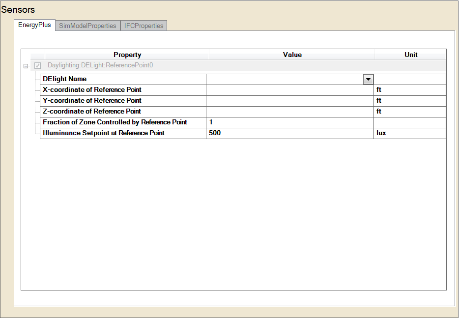
Daylighting:DELight:ReferencePoint | |
|
Virtual Sensor |
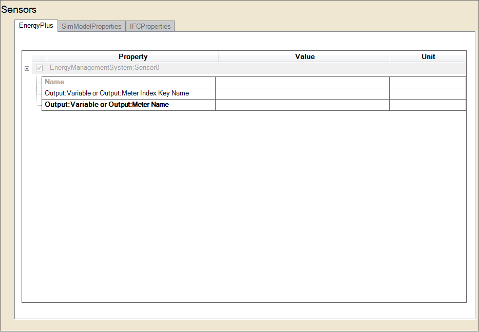
Ems Sensor | EnergyManagementSystem:Sensor |
| Temperature Sensor | Dry Bulb Wet Bulb Radiant |
Sensor:Temperature:DryBulb Sensor:Temperature:WetBulb Sensor:Temperature:Radiant |
|
Relative Humidity |
Type 1 Type 2 |
Sensor:Humidity:Relative Sensor:Humidity:Relative |
|
Gas Sensor |
CO2 Sensor | Sensor:Gas:Co2 |
The name of the Daylighting:DELight:Controls object instance hosting this Reference Point. The drop down list will display the available library entries that have been developed and/or were packaged with the install for Libraries/Controllers; Daylighting (type).
These three fields are the X, Y and Z values of the Reference point in the coordinate system you specified for daylighting reference points in the GlobalGeometryRules object. The figure shows an example using the relative coordinate (to zone) system. Z is typically at work surface height (e.g., 0.8m for a desk).
Source: EnergyPlus Input Output Reference - Example showing location of two daylighting reference points in the zone coordinate system (relative) of a rectangular zone with three windows. (a) Perspective view, (b) plan view, (c) elevation view. All dimensions are in meters.
The zone floor-area fraction of the electric lighting that is controlled by the daylight illuminance at this Reference Point. If the sum of the values for this field for all Reference Points input for a given daylighting zone is less than 1.0, then the remaining fraction (i.e., 1.0 – Sum) is assumed to not have lighting control.
Note: that Reference Points may be input with a 0.0 value for this fraction. In this case, daylight factors and interior illuminance values will be calculated for the Reference Point, but it will play no role in controlling the electric lighting within the daylighting zone to which it belongs.
The desired lighting level (in lux) at this Reference Point. This is assumed to be the lighting level that would be produced at this reference point at night if the overhead electric lighting were operating at full input power. Recommended values depend on the type of activity and may be found, for example, in the Lighting Handbook of the Illuminating Engineering Society of North America. A typical value for general office work (excluding computer terminals) is 500 lux.
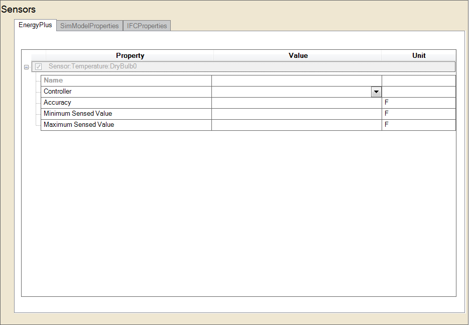
Same properties as Temperature Sensor (shown above)
Same properties as Temperature Sensor (shown above)
______________________________________________________________________________________
© Copyright 2013 Simergy, Sustainable IQ, Inc.