Location = Templates/System Templates/Air Loops
The air distribution portion of the HVAC system is determined by configuration of the air loop(s). A complete air loop is composed of a supply side and a demand side. The supply side is composed of different component shapes, such as coils, pumps and fans, that are connected and contain the required properties so that EnergyPlus can run effectively. In addition, controllers can be connected to a number of different components, which allows a range control types and schemes to be introduced into the air loop. When working in the air loop workspace you can create the supply side of the air loop. Once an air loop template has been saved to the source library it is an option for you to select when you are creating an air loop in your model in the Systems: Air Loops Create/Edit workspace. The demand side of the air loop can either be created from scratch in the energy model or you can select Zone HVAC Group Templates to drag and drop onto the air loop within the Systems: Air Loops Create/Edit workspace.
The Air Loops workspace is broken down into five main areas described in the System Templates Workspace, and is very similar in composition and capabilities to the Air Loops Create & Edit Workspace. The user can visualize, edit and create new Air Loop Templates, which can be used to define the supply side for the air loop in their models. The things that are unique to the air loop for the six main areas are described below.
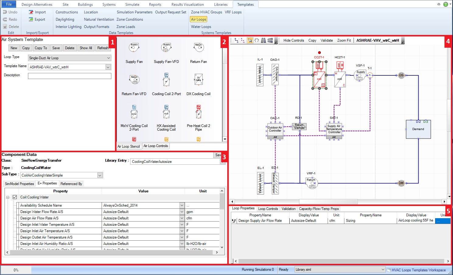
1. System Template Naming/Selection Area the drop down list where the templates from the active source library can be selected, and descriptions can be associated with each template as well.
2. Stencils
The Air Loop Stencil contains all the available components shapes and properties that can be used on an air loop
The Air Loop Controls/Sensors Stencil contains all the available controller shapes and properties that can be used on an air loop
3. Component Properties Displays the properties for the component selected within the HVAC diagramming area.
4. HVAC Diagramming Canvas - the loop creation playground where the component shapes can be dragged and dropped onto, different components can be connected, components selected to edit properties and other features.
You can input a specific value for the cfm for the design supply air flow or you can select "autosize".
Select a Libraries:Sizing Params library entry that establishing the sizing parameters for the overall air loop.
5. Loop Level Controls - displays the current Availability Managers that are defined for the template.
5. Validation - The location where the error messages are displayed after the Air Loop Ruleset has been run (Validate)
The table displays the Air System Templates that are included with version 1. The Air Loop System templates utilize a naming convention, so that the names can be represented in an abbreviated manner.
Air System Templates |
Full Name & Description |
| ASHRAE_CAV_dXc_gasH-PSZ | |
| ASHRAE_CAV_HPAta-PSZ | |
| ASHRAE_VAV_dxC_elecH | |
| ASHRAE_VAV_dxC_wtrH | |
| ASHRAE-VAV_wtrC_elecH | ASHRAE system required inputs for a Variable Air Volume system with chilled water coils and electric heating coils |
| ASHRAE-VAV_wtrC_wtrH | ASHRAE system required inputs for a Variable Air Volume system with chilled water coils and hot water coils |
| CAV_dxC_gasH | Constant Air Volume with DX cooling coils and gas heating coils |
| CAV_wtrC_gasH | Constant Air Volume with chilled water coils and gas heating coils |
| CAV_wtrC_wtrH | Constant Air Volume with chilled water coils and hot water coils |
| DOAS_CAV_dxC_gasH_HR | |
| DOAS_CAV_wtrC_wtrH_HR | |
| Furn_dxC_gasH | Furnace with DX cooling coils and gas heating coils |
| HP_Ata | Heat Pump that is Air to Air |
| UnitH | Unit Heater |
| VAV_dxC_elecH | Variable Air Volume system with DX cooling coils and electric heating coils |
| VAV_dxC_gasH |
|
| VAV_dxC_wtrH | Variable Air Volume system with DX cooling coils and hot water coils |
| VAV_dxC_wtrSTM | |
| VAV_SD_wtrC_wtrH | Variable Air Volume system with chilled water coils and hot water coils |
| VAV_wtrC_elecH | Variable Air Volume with chilled water coils and electric heating coils |
| VAV_wtrC_gasH | Variable Air Volume with chilled water coils and gas heating coils |
| VAV_wtrC_wtrH | Variable Air Volume system with chilled water coils and hot water coils |
| VAV_wtrC_wtrH_HR | Variable Air Volume system with chilled water coils and hot water coils, as well as a heat exchanger |
| WSHP | Water Source Heat Pump
|
| DD_DVAVFan_wtrC_wtrH |
______________________________________________________________________________________
© Copyright 2013 Simergy, Sustainable IQ, Inc.