Stencil: Zone HVAC Stencil: Grp-VAV Series PIU
Type: Air Terminal
Sub Type: SeriesPIU_Reheat
![]()
Note: Requires a connection to a hot water loop
EnergyPlus Object - AirTerminal:SingleDuct:VAV:SeriesPIU
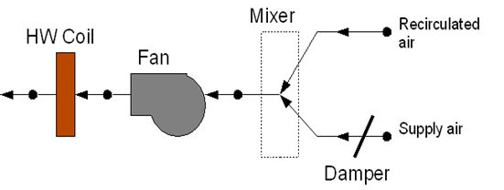
The series powered induction unit is an air system terminal unit that mixes varying amounts of secondary (recirculated) air and primary (conditioned supply) air to produce a fixed flow of air to a zone. The unit contains a small fan that acts to induce the secondary air and a heating coil for heating the mixed secondary and primary air. The fan runs at a constant volume flow rate whenever the unit is on (and the fan’s availability schedule is on or it is activated by an availability manager). The fan is downstream of the primary and secondary air inlets. The variable mixing is accomplished by a damper in the unit’s primary air supply inlet duct. This damper can move from fully open (100% primary air. 0% secondary air) to a minimum stop that is specified in the input description. At full cooling the damper will be fully open. At minimum cooling and for heating the damper will be at the minimum stop and the secondary air flow will be at its maximum.
The EnergyPlus model of the series PIU terminal unit is composed of three components: a zone mixer, a constant volume fan, and a heating coil (hot water, electric, or gas).
The table shows the properties that are displayed when the component is selected while in diagram mode. The second column shows the selection options available that are dictated by EnergyPlus or it shows the source for the library entries that are displayed in the drop down list.
| Property Name | Value Sources/Options |
|
Name |
Simergy provides unique name (editable) |
|
Availability Schedule Name |
|
|
Maximum Air Flow Rate |
value, Autosize |
|
Maximum Primary Air Flow Rate |
value, Autosize |
|
Minimum Primary Air Flow Fraction |
value, Autosize |
|
Fan Name |
Libraries/Plant and Equip/Fans & Pumps/Supply Fan |
|
Reheat Coil Name |
|
|
Maximum Hot Water or Steam Flow Rate |
0, Autosize |
|
Minimum Hot Water or Steam Flow Rate |
0-Min; 0 default |
|
Convergence Tolerance |
0-Min; 0.001 Default |
Simergy automatically defines a unique name for each component. This can be changed by the user if desired.
The name of the schedule (ref: Schedule) that denotes whether the unit can run during a given hour. A schedule value greater than 0 (usually 1 is used) indicates that the unit can be on during the hour. A value less than or equal to 0 (usually 0 is used) denotes that the unit must be off for the hour.
The maximum volumetric air flow rate through the unit in cubic meters per second. Since this is a constant air volume unit, this is also the design, rated air flow rate of the unit.
The maximum volumetric air flow rate of primary air through the unit in cubic meters per second. This is the primary air flow rate at full cooling load when the primary air damper is fully open. Usually this quantity is the same as the total unit flow rate, but it can be less.
The minimum volumetric air flow rate of primary air through the unit expressed as a fraction of the maximum volumetric air flow rate of primary air. This input can be 0.0.
The name of an zone mixer component (object: AirLoopHVAC:ZoneMixer) which composes part of the unit. Note that some of the input for the mixer will duplicate input fields of the powered induction unit. One of the zone mixer inlet nodes should be the same as the supply air inlet node of the PIU; the other inlet node of the zone mixer should be the same as the secondary air inlet node of the PIU. The outlet node of the zone mixer should be the same as the inlet node of the PIU fan.
The name of a fan component which composes part of the unit. Note that the fan’s maximum flow rate should be the same as the maximum air flow rate of the PIU and the type of fan object must be Fan:ConstantVolume. The fan’s inlet node should be the same as the zone mixer’s outlet node. The fan’s outlet node should be the same as the heating coil’s air inlet node. The secondary fan will run according to the Availability Schedule specified in the Fan:ConstantVolume object, unless it is overridden by an availability manager (ref. AvailabilityManager:NightCycle and others).
The name of the heating coil component which composes part of the unit. Note that the heating coil’s air inlet node is the same as the fan outlet node and the heating coil’s air outlet node is the same as the PIU outlet node.
The maximum hot water volumetric flow rate in m3/sec through the unit’s heating coil. If the heating coil is gas or electric this field should be blank.
The minimum hot water volumetric flow rate in m3/sec through the unit’s heating coil. If the heating coil is gas or electric this field should be blank.
The name of the HVAC system node which regulates the flow of hot water through the unit. This should be the same node as the water inlet node of the unit’s hot water coil. For gas or electric heating coils, this input should be blank.
The control tolerance for the unit heating output. The unit is controlled by matching the unit output to the zone demand. For units with water coils, the model must be numerically inverted to obtain a specified output. The convergence tolerance is the error tolerance used to terminate the numerical inversion procedure. Basically this is the fraction:
For gas or electric heating coils, this input should be left blank. The default is 0.001.
______________________________________________________________________________________
© Copyright 2013 Simergy, Sustainable IQ, Inc.