For EnergyPlus to successfully calculate zone design heating and cooling loads and air flow rates and for EnergyPlus to use these results to automatically size the HVAC components a number of input values must be present in the IDF file.
Simergy streamlines the input process and coordination for these two areas. The design heating and cooling loads are described in detail below and the input process for the air flow rates is described in Design Air Flow Rates.
Certain input fields must have values entered in Simergy. These inputs for a number of different use scenarios have been set up within the Source Libraries that are packaged with the installation of Simergy or you can edit and build your own. The important thing to remember is that in a majority of cases the 'Input Structure' of Simergy from the top down is:
Simulate > Simulation Configuration - you can select a Simulation Parameters template that is packaged with Simergy or create your own.
Templates > Simulation Parameters - you can use one packaged with Simergy or create your own and select the desired library entry
Libraries > Sim Params - you can use one packaged with Simergy or create your own.
Simergy automatically handles coordination of different object types. This automation reduces the need for the manual coordination typically required within EnergyPlus, which is a significant time saver as well as reducing the potential for 'user error' in setting up the simulation. Key coordination areas include:
In EnergyPlus the sizing calculations generally know nothing about the system control inputs such as setpoints and availability schedules, so the user must coordinate sizing inputs with the actual simulation control inputs.
In EnergyPlus schedules for internal loads, heating and cooling thermostats and other heating and cooling equipment must be carefully coordinated
The EnergyPlus input file needs to contain a SimulationControl object. To do this in Simergy:
Library Entry Level - A library entry in the Libraries > Sim Params workspace needs to be created and used. The specifics for the Library Entry include:
Figure: An example of a Libraries > Sim Params library entry that could be used.
If there are no air or water loops in the HVAC system Simulation Control fields 2 and 3 can be set to No.
If there are one or more air loops (i.e., there is at least one AirLoopHVAC object in the input file) then the 2nd field Do System Sizing Calculation should be entered as Yes.
If there are one or more water loops (Plant Loop objects) then the 3rd field Do Plant Sizing Calculation should be set to Yes.
Finally either the 4th field (Run Simulation for Sizing Periods) or the 5th field (Run Simulation for Weather File Run Periods) should be set to Yes in order to autosize the components and do a real simulation using the autosized components.
Template Level - The Sim Params library entry needs to be included in a template (Templates > Simulation Parameters). The Sim Params library entry should be selected for the General Simulation Parameters field within the Simulation Control Property Category.
Figure: An example of the Templates > Simulation Parameters workspace with a Template that has the General Simulation Parameters field specified.
Simulation Configuration - Finally within the Simulate workspace you will need to select the Simulation Parameters Template to associate it with a Configuration, so that the desired results will be created.
Figure: A simulation configuration that has a Simulation Parameters template selected.
Note: The Simulation Parameters Template can also be accessed from this workspace by selecting the Edit Template button.
What Happens - By having "Do Zone Sizing Calculation" set to "yes", this will cause a zone sizing simulation to be done using all the sizing periods in the input file as weather. The component autosizing calculations are done on the first pass through the HVAC system in the real simulation.
The EnergyPlus input file needs at least two Sizing Period objects present (normally one for Summer and one for Winter). To do this in Simergy:
[Find]
To incorporate a global sizing factor in the EnergyPlus simulation include the Sizing:Parameters object. To do this in Simergy:
Library Entry Level - Set up or Use a Libraries > Sizing Params library entry where the "Heating Sizing Factor" and the "Cooling Sizing Factor" have input values for the HvacDesign Type and Sizing Sub Type.
Template Level - Then select the library entry for the "Global Sizing Parameters" field on the Simulation Parameters Template.
Simulation Configuration - Finally within the Simulate workspace you will need to select the Simulation Parameters Template to associate it with a Configuration, so that the desired results will be created.
In EnergyPlus:
For each controlled zone in the input file there should be a corresponding Sizing:Zone object.
Similarly for each AirLoopHVAC there should be a Sizing:System object.
And for each Plant or Condenser Loop there should be a Sizing:Plant object.
Library Entry Level - In Simergy each of these objects can be accessed from the same workspace - Libraries > Sizing Params, however the sub types differ for each:
For Zone Groups - Type = HvacDesign; Sub Type = ZoneSizing gives you access to the Sizing:Zone fields
For Air Loops - Type = HvacDesign; Sub Type = AirLoopSizing gives you access to the Sizing:System fields
For Water Loops - Type = HvacDesign; Sub Type = WaterLoopSizing gives you access to the Sizing:Plant fields
Template Level - at this level in Simergy each of the three are assigned to templates in different workspaces:
For Zone Sizing = Templates > Zone Conditions; Category = Zone Sizing; Field = Zone Sizing
For Air Loop Sizing = Templates > Air Loops; You can select the Air Loop Sizing library entry from the "Sizing" field in the Air System Parameters section.
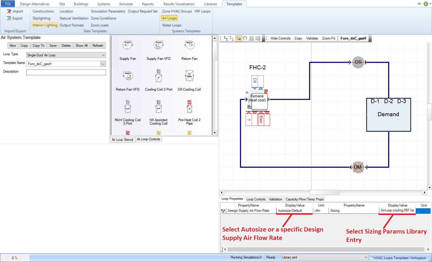
Figure: Templates > Air Loops workspace. Sizing drop down list where Air Loop Sizing library entry can be selected is highlighted.
For Water Loop Sizing = Templates > Water Loops: You can select the Water Loop Sizing library entry from the "Sizing" field in the Water System Parameters section.
Note: Each water loop type (Chilled Water, Hot Water, Condenser Water and Mixed Water) have their own template workspaces.
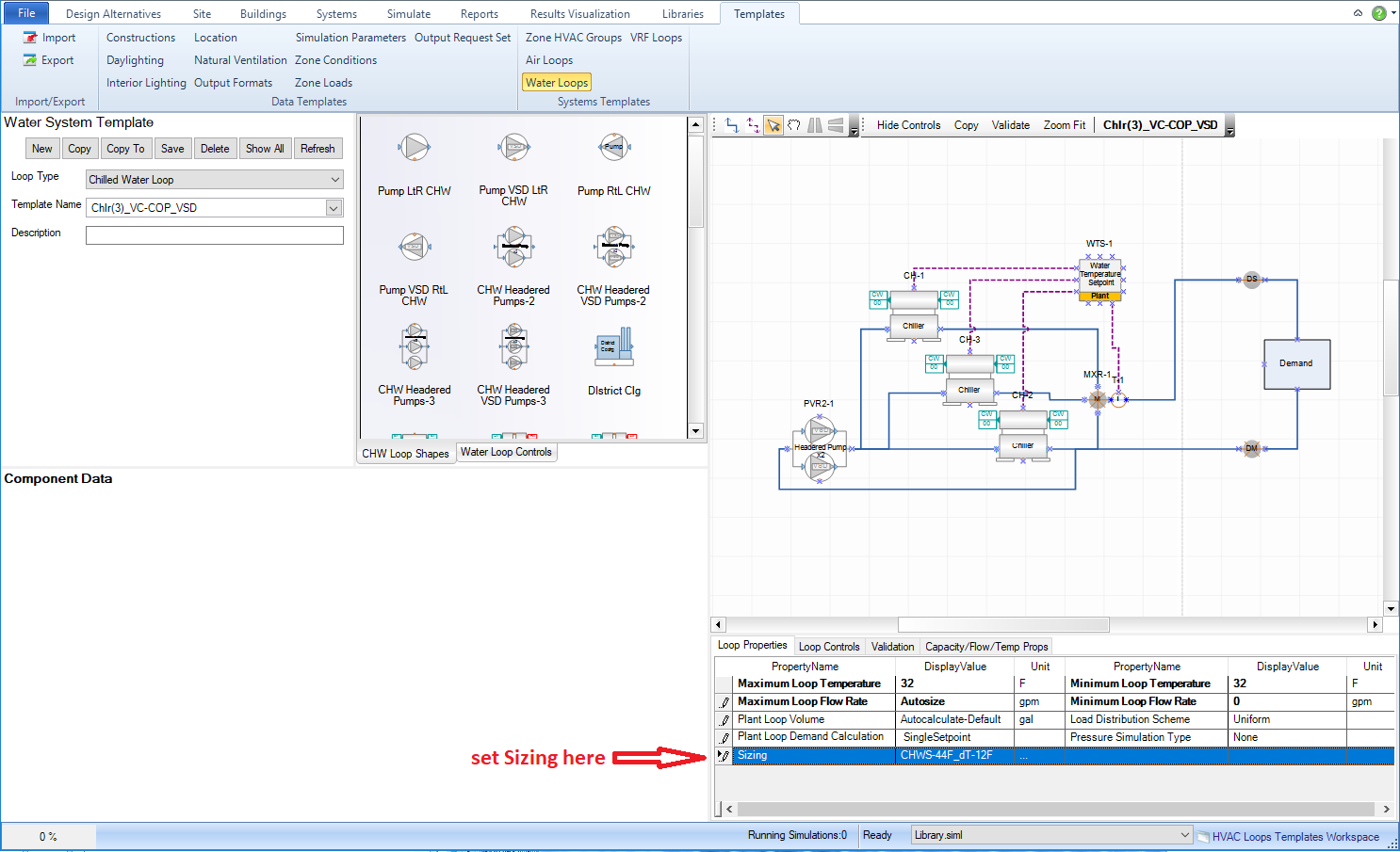
Figure: Templates > Chilled Water Loops workspace. Sizing drop down list where Water Loop Sizing library entry can be selected is highlighted.
Note: the location of these fields for each water loop type is the same.
To Incorporate into Simergy Model - the templates need to be selected within various locations within Simergy
For Zone Groups - the Zone Conditions template is assigned in the Buildings > Zone Grouping Workspace for each Zone Group that is set up.
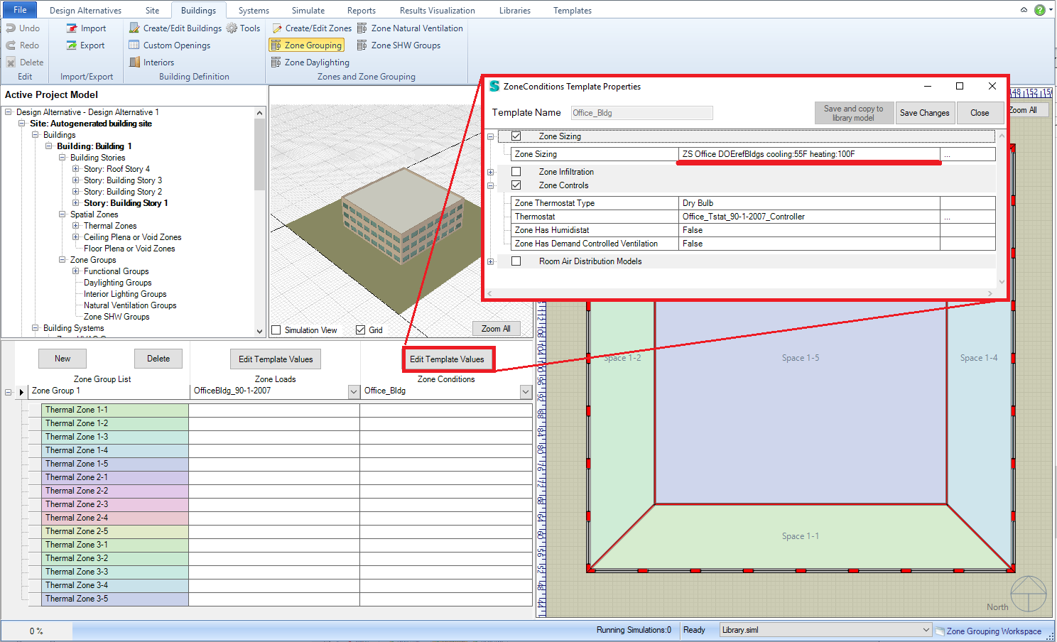
Figure: Buildings > Zone Grouping workspace. The Zone Conditions drop down list for the Zone Group is highlighted.
For Air Loops - You can select the Air Loop Template that contains the Air Loop Sizing or you can specify it for any template selected by making a selection from the "Sizing" field drop down list in the Air System Parameters table below the 2d diagram.
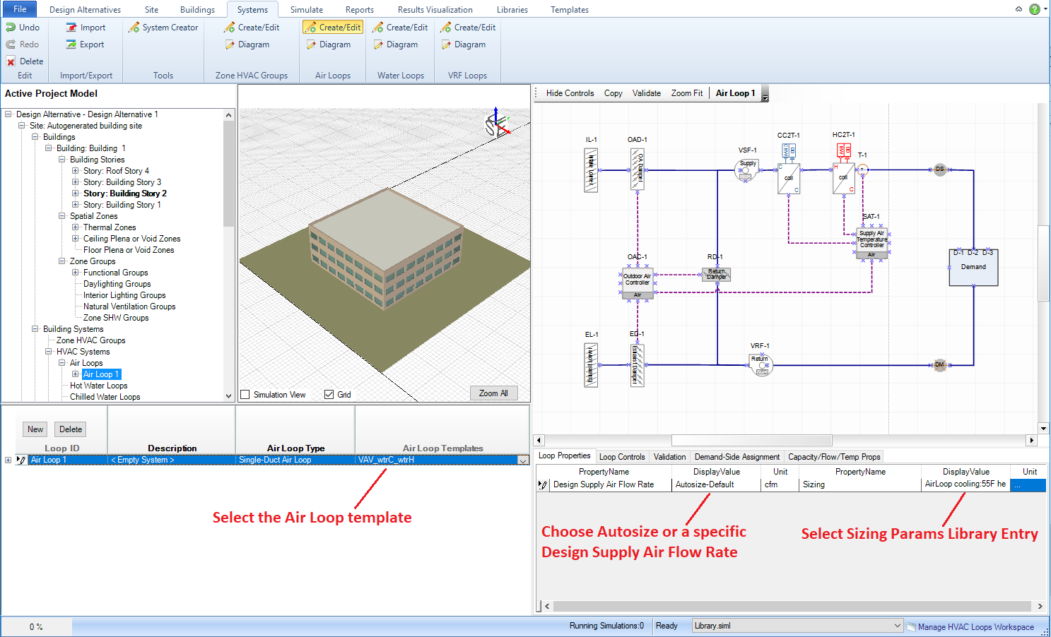
Figure: Systems > Air Loops > Create/Edit workspace. The field where the Air Loop Template can be selected is highlighted on the left, and the Air Loop Parameters field in the table below the 2d diagram on the right can be used to override the selection associated with the Air Loop Template.
For Water Loops - each different type of water loop template (HW, CHW, CW, MxW) can be assigned to the different water loops created. You can select the Water Loop Template that contains the Water Loop Sizing or you can specify it for any template selected by making a selection from the "Sizing" field drop down list in the Air System Parameters table below the 2d diagram.
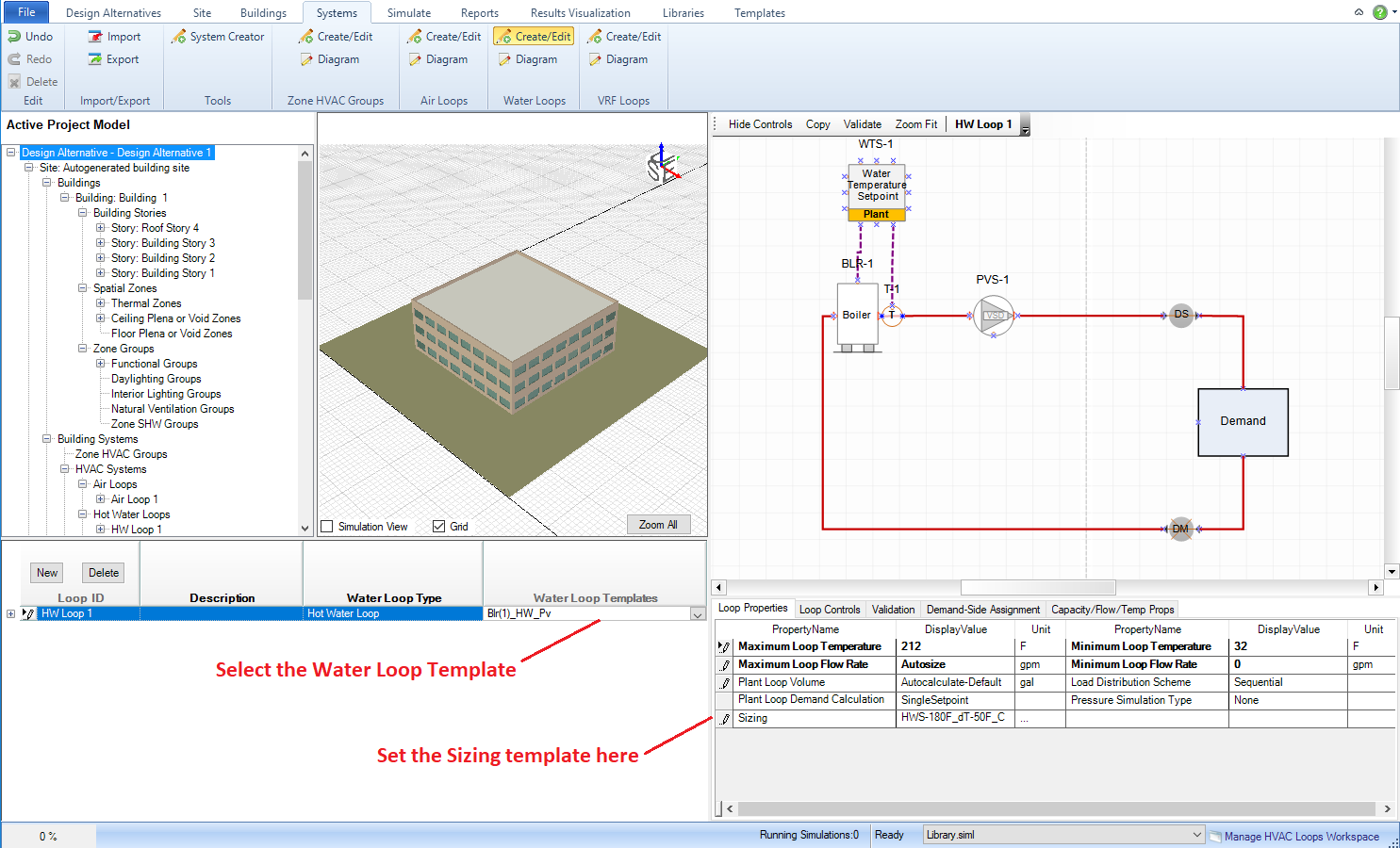
Figure: Systems > Water Loops > Create/Edit workspace. The field where the Water Loop Template can be selected is highlighted on the left, while the Hot Water Loop Parameters field in the table below the 2d diagram on the right can be used to override the selection associated with the Hot Water Template.
______________________________________________________________________________________
© Copyright 2013 Simergy, Sustainable IQ, Inc.