Location = Libraries/Plant and Equipment/Air Terminals
The Type and Sub Type options that can be selected from the drop down lists in that area of the workspace, which filter the Source Library to display the variables the user can select to include, along with a value, in a Library Entry.
Note: The links within the table are to the EnergyPlus Input Output Reference and the explanations of the objects.
| Select Type Options | Select Sub Type Options | Property Category |
AirTerminal |
Uncontrolled VAV_NoReheat VAV_HeatandCool_NoReheat ConstantVolume_Reheat VAV_Reheat VAV_Reheat_VariableSpeedFan VAV_HeatandCool_Reheat SeriesPIU_Reheat ParallelPIU_Reheat CAV_ActiveCooledBeam CAV_PassiveCooledBeam CAV_FourPipeInduction CAV_FourPipeBeam AirTerminal_DualDuct_ConstantVolume AirTerminal_DualDuct_VAV AirTerminal_DualDuct_VAV_OutsideAir |
AirTerminal:Uncontrolled AirTerminal:SingleDuct:VAV:NoReheat AirTerminal:SingleDuct:VAV:Heatandcool:NoR AirTerminal:SingleDuct:ConstantVolume:Reheat AirTerminal:SingleDuct:VAV:Reheat AirTerminal:SingleDuct:VAV:Reheat:VariableSp AirTerminal:SingleDuct:VAV:HeatandCool:Reh AirTerminal:SingleDuct:SeriesPIU:Reheat AirTerminal:SingleDuct:ParallelPIU:Reheat AirTerminal:SingleDuct:ConstantVolume:Cool AirTerminal:SingleDuct:ConstantVolume:Cool
AirTerminal:DualDuct:ConstantVolume AirTerminal:DualDuct:VAV AirTerminal:DualDuct:VAV:OutsideAir |
ElectricTerminalInterior |
LightingFixture |
|
Terminal Unit |
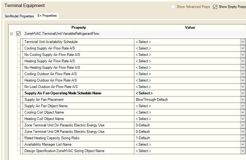
VariableRefrigerantFlow |
|
Property Group: Air Terminal:SingleDuct:Uncontrolled
Property Group: Air Flow Network:Distribution:Component:Terminal Unit
Property Group: AirTerminal:SingleDuct:VAV:Reheat
Property Group:AirflowNetwork:Distribution:Component:TerminalUnit
Property Group: Air Terminal: Single Duct:Constant Volume:CooledBeam
Property Group:AirflowNetwork:Distribution:Component:TerminalUnit

______________________________________________________________________________________
© Copyright 2013 Simergy, Sustainable IQ, Inc.