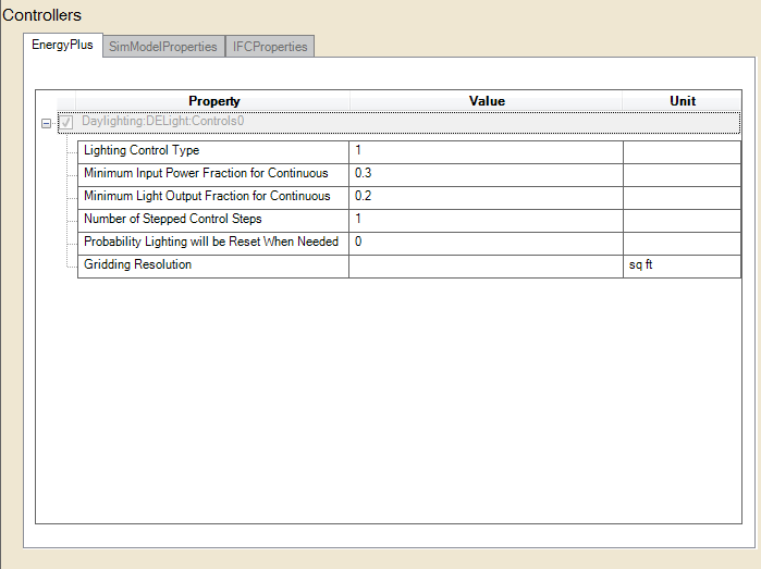
Defines the parameters of each daylighting zone within a building. This object must be associated with a specific thermal zone within the building for which the reduction in electric lighting due to daylight illuminance will be accounted.
The type of overhead electric lighting control. All reference points specified are assumed to have this type of control.
For Lighting Control Type = 1 (continuous), the overhead lights dim continuously and linearly from (maximum electric power, maximum light output) to (minimum electric power, minimum light output) as the daylight illuminance increases. The lights stay on at the minimum point with further increase in the daylight illuminance.
For Lighting Control Type = 2 (stepped), the electric power input and light output vary in discrete, equally spaced steps. The number of steps is given by Number of Steps (Excluding Off) of Stepped Control. For example, if Number of Steps = 3 and Illuminance Setpoint = 600, then the following table shows the fraction of the lights that are on vs. daylight illuminance.
|
Example of a Stepped Lighting Control System with Three Steps |
|
|
Daylight illuminance |
Fraction of lights that are on |
|
0-200 |
1.0 |
|
200-400 |
2/3 |
|
400-600 |
1/3 |
|
600 and above |
0.0 |
Lighting Control Type = 3 (continuous/off) is the same as Lighting Control Type = 1 except that the lights switch off completely when the minimum dimming point is reached.
For Lighting Control Type = 1 (continuous), the lowest power the lighting system can dim down to, expressed as a fraction of maximum input power. For Lighting Control Type = 3 (continuous/off) this is the power fraction reached just before the lights switch off completely.
For Lighting Control Type = 1 (continuous), the lowest lighting output the lighting system can dim down to, expressed as a fraction of maximum light output (see figure, above). This is the fractional light output that the system produces at minimum input power. For Lighting Control Type = 3 (continuous/off) this is the power fraction reached just before the lights switch off completely.
The number of steps, excluding off, in a stepped lighting control system. Required and must be >0 if Lighting Control Type = 2. The steps are assumed to be equally spaced.
May be specified if a stepped lighting control system (Lighting Control Type = 2) is manually operated, such as in a simple, one-step (on-off) system. Gives the probability the occupants of a daylit zone will set the electric lights to the correct level to obtain the required illuminance. The rest of the time the lights are assumed to be set one step too high. For example, consider an on-off lighting system (Number of Steps = 1) with a set point of 600 lux and 0.7 reset probability. Then, when daylighting exceeds 600 lux, the electric lights will be off 70% of the time and on 30% of the time.
The maximum surface area for nodes in gridding (subdividing) all surfaces in the DElight zone. All reflective and transmitting surfaces will be subdivided into approximately square nodes that do not exceed this maximum. Higher resolution subdivisions require greater calculation times, but generally produce more accurate results. This same gridding resolution is also used to subdivide any Complex Fenestration System surfaces. It is advisable to perform at least one simulation of new input using a small gridding resolution such as 0.1m2 to compare these results against simulation runs at lower resolution (i.e., higher maximum area nodal grids) to get a sense of possible levels of error.
______________________________________________________________________________________
© Copyright 2013 Simergy, Sustainable IQ, Inc.