Importing a DWG/DXF file is actually done on the 2d building canvas area in the Buildings workspace.
Eliminate as much unnecessary information from the DWG/DXF file as is feasible.
Explode ALL blocks within the file. Note: Currently the user is not able to do this within Simergy
Remove unnecessary layers
Become familiar with the layers that are included in the file and identify the layers that are most relevant.
Important: The amount of components, points and really data that are "active" in a DWG/DXF file that is imported into Simergy has a significant influence on computational bandwidth that is utilized by Simergy and therefore on the amount of time ceratin tasks will take to be fully executed. Therefore it is beneficial to have only the layers (data) displayed that are needed to effectively work with the DWG/DXF file. For example, if the DWG/DXF imported file is large in size, then it is very important to only have the layers active that are truly needed.
Step 1 - Go to the Buildings tab on a New Project.
Note: The import will be associated with the Design Alternative that is currently selected.
Step 2 - Click "New" and Select Freeform( DWG/DXF draw-over ) at the bottom of the Shape dropdown
this will bring up the Layers dialog box where you can click "choose file"to browse for a DWG or DXF to import
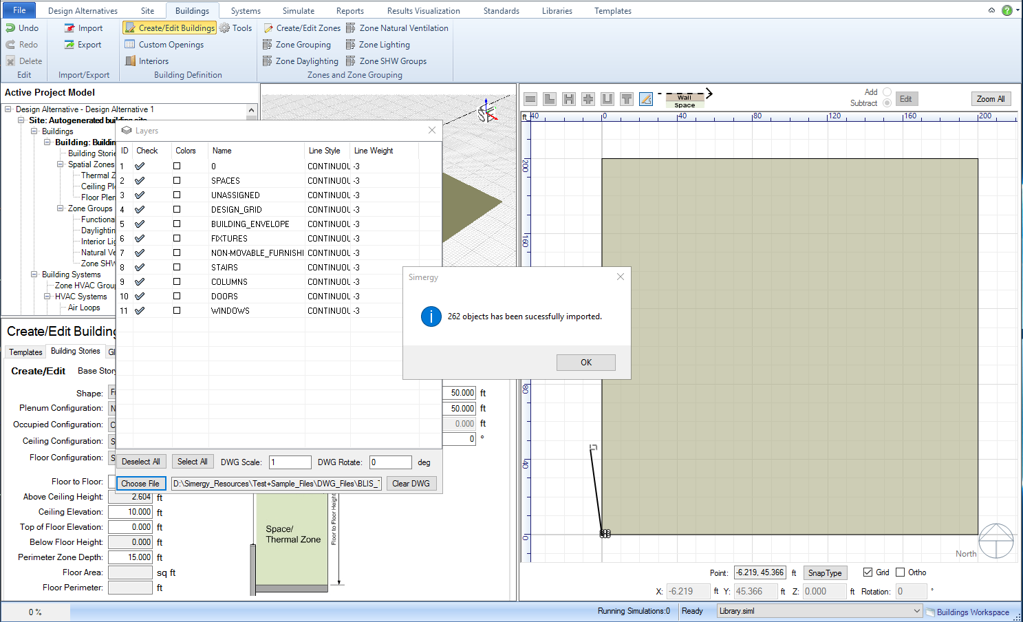
Step 3 - Browse and Select the desired file.
Once the DWG/DXF file has been selected, the Layers Dialog box will be populated with layers and a message stating that the file has been successfully loaded in Simergy.
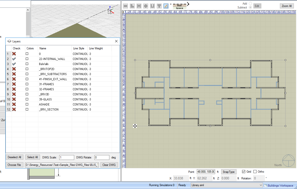
Step 4 - Click on the site to place the drawing. The user will choose a location to place the reference point for the drawing- the bottom left corner of the drawing's bounding box. After placing the drawing, it is helpful to deselect Layers that are not being used. The user can do this by selecting Deselect All. Then they can select individual Layers to turn back on by selecting on the "X", which will then change to a "checkmark".
Tip: Move the Layers Dialog box to the side or to a separate screen because it can remain active while the user is working in the 2D view. One thing this allows is that the user can visualize in the 2D view what is shown and/or removed by selecting different Layers.
When the user is done working with the Layers dialog box they can either leave it open or close it by selecting the "x" in the upper right. The changes are Saved automatically, so no save or update is required.
Tip: If the user wants to return to the Layers dialog box at any time they can just select the DWG/DXF button at the bottom right of the 2D palette.
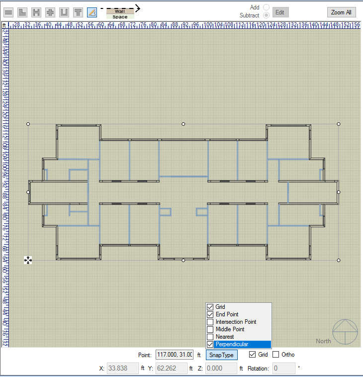
Step 5 - Change the Settings to make the Tracing Process easier
The following are recommended settings if the user is tracing a DWG/DXF that is similar to the one shown to create the BEM Geometry:
Deselect Grid (most likely it is not going to be beneficial to include)
Check Ortho (makes the drawing and selection process easier)
Snap Type - only have End Point and Perpendicular selected
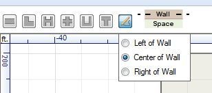
The user can also specify which side of the reference line on which the walls will be generated by clicking the button with the image of a pencil drawing a line
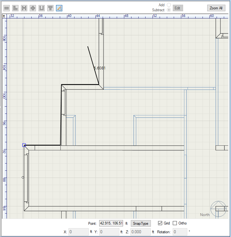
Step 6 - Draw the Geometry
When the user has closed the shape (user connects the last line drawn to the starting point) the geometry will appear in the 3d view
Step 7 - Make any other adjustments as needed and select Save in the Create/Edit Building Stories Area.
______________________________________________________________________________________
© Copyright 2013 Simergy, Sustainable IQ, Inc.