Shape Components represent HVAC Components within a HVAC system. Simergy currently contains ~200 different component shapes, which are grouped into six main areas of HVAC System Design:
Zone HVAC Groups
Air Loops
Water Loops (Hot Water, Chilled Water, Mixed Water and Condenser Water Loops)
In Simergy the Component Shapes are grouped into 12 stencils that are accessible to the user in the Diagram Workspace for Zone HVAC Groups, Air Loops and Water Loops on the Systems Tab. Each workspace contains two shape stencils. One for the component shapes and one for the controls and sensor shapes.
Appearance: The overall appearance of the component shapes is intended to look familiar to engineers and energy modelers, because it is working to be representative of the engineering drawings that they are typically creating and/or analyzing for projects. However, where the drawings imply integration within Simergy it is required.
The shapes are used to build and/or edit the loops, which are representative of typical engineering loop diagrams.
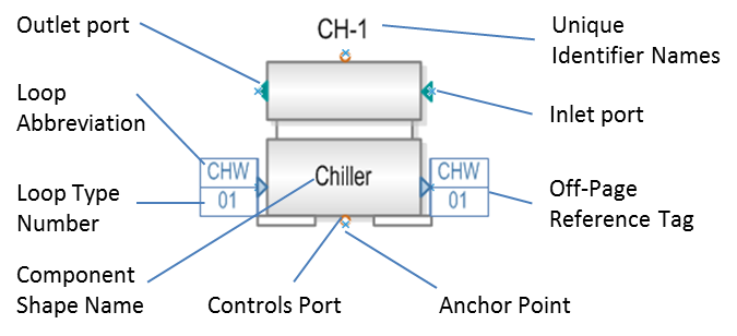
The different parts of the component shapes are described in detail here.
Off-Page Reference Tags: An important part of the HVAC System design framework are the off-page reference tags and the role they play in integrating the HVAC System Air and Water Loops. They also allow the user to track and review the different parts of the HVAC System design. Off-page references are used on shapes that are required to be linked to a different type of loop. For the example shown above this Chiller component shape would be the one the user would see located on the condenser loop. The off-page references indicate that it needs to be linked to a chilled water loop. By default the off-page references will be displayed with the required Loop abbreviation on top (in this case CHW = Chilled Water) and a Loop Type Number on the bottom (default = 00). The user can tell when the component shape has been linked when the Loop Type Number is another number besides 00.
To assign the component shape to another loop the user needs to go through a few steps:
Make sure the other loop type has been set up. In this case, a Chilled Water Loop.
If this hasn't been done the user would go to the Systems/Water Loops/Create Edit workspace and add a water loop.
Then they would select the water loop type (Chilled Water), and select an appropriate template to set up the loop
Once the Chilled Water loop has been set up, return to the Condenser Loop
Select the Chiller Shape Component
Look to the Component Shape Properties field on the lower left side of the workspace.
Under Selected Component Information there should be a line item titled Chilled Water Loop. Select the Chilled Water Loop that you just created from the drop down list.
Now the Chiller Shape component is linked to the Chilled Water loop, which is indicated by the Loop Type Number on the off-page reference tag changing to '01', if that is the only chilled water loop that is part of the model.
In addition, you can return to the chilled water loop and you will see a representative shape with an off page reference showing a link back to the condenser loop.
______________________________________________________________________________________
© Copyright 2013 Simergy, Sustainable IQ, Inc.